Rexroth PSI 6xxx.105xx Edition 01 Mittelfrequenz-Umrichter...
32
Typspezifische Anleitung | Type-Specific Instructions Electric Drives and Controls Pneumatics Service Linear Motion and Assembly Technologies Hydraulics Rexroth PSI 6xxx.105xx Mittelfrequenz-Umrichter Medium-Frequency Inverter R911172828 Edition 01 ENGLISH DEUTSCH
Transcript of Rexroth PSI 6xxx.105xx Edition 01 Mittelfrequenz-Umrichter...

Typspezifi sche Anleitung | Type-Specifi c Instructions
Electric Drivesand Controls Pneumatics Service
Linear Motion and Assembly TechnologiesHydraulics
Rexroth PSI 6xxx.105xxMittelfrequenz-Umrichter Medium-Frequency Inverter
R911172828Edition 01
EN
GLI
SH
DE
UTS
CH

Die angegebenen Daten dienen der Produktbeschreibung. Sollten auch Angaben zur Verwendung gemacht werden, stellen diese nur Anwendungsbeispiele und Vorschläge dar. Katalogangaben sind keine zugesicherten Eigenschaften. Die Angaben entbinden den Verwender nicht von eigenen Beurteilungen und Prüfungen. Unsere Produkte unterliegen einem natürlichen Verschleiß- und Alterungsprozess.
Alle Rechte bei Bosch Rexroth AG, auch für den Fall von Schutzrechtsanmeldungen. Jede Verfügungsbefugnis, wie Kopier- und Weitergaberecht, bei uns.
Auf der Titelseite ist eine Beispielkonfiguration abgebildet. Das ausgelieferte Produkt kann daher von der Abbildung abweichen.
Der deutsche Teil der Typspezifischen Anleitung beginnt auf Seite 5, der englische Teil beginnt auf Seite 19.
Sprachversion des Dokumentes DE und EN
Originalsprache des Dokumentes: DE
These Type-Specific Instructions of the Rexroth Medium-Frequency Inverter contains the descriptions in both German and English. The German part of the Type-Specific Instructions starts at page 5, the English part starts at page 19.

R911172828 | PSI 6100.105xx Bosch Rexroth AG 3/32
Inhalt
DEU
TSC
H
Inhalt 1 Zu dieser Dokumentation............................................................................. 5
1.1 Gültigkeit der Dokumentation ............................................................. 5 1.2 Erforderliche und ergänzende Dokumentationen ............................... 5 1.3 Darstellung von Informationen ........................................................... 6
1.3.1 Sicherheitshinweise............................................................ 6 1.3.2 Symbole ............................................................................. 6 1.3.3 Bezeichnungen................................................................... 6 1.3.4 Abkürzungen ...................................................................... 6
2 Sicherheitshinweise..................................................................................... 7 3 Allgemeine Hinweise vor Sachschäden und Produktschäden ...................... 7 4 Lieferumfang ............................................................................................... 7 5 Anschlussplan ............................................................................................. 8 6 Ein/Ausgangsfeld ........................................................................................ 8
6.1 Diskretes 24V Ein-/Ausgangsfeld..................................................... 12 6.2 Sonstige Ein- /Ausgänge:................................................................. 13
7 Merkmale .................................................................................................. 14 7.1 Besonderheiten ................................................................................ 14
7.1.1 Schweißkreis Freischaltung.............................................. 14 8 Statuscodes .............................................................................................. 15 9 Ablaufdiagramme ...................................................................................... 16

4/32 Bosch Rexroth AG R911172828 | PSI 6100.105xx
Inhalt
R911172828 | PSI 6100.105xx Bosch Rexroth AG 5/32
Zu dieser Dokumentation
DEU
TSC
H
1 Zu dieser Dokumentation
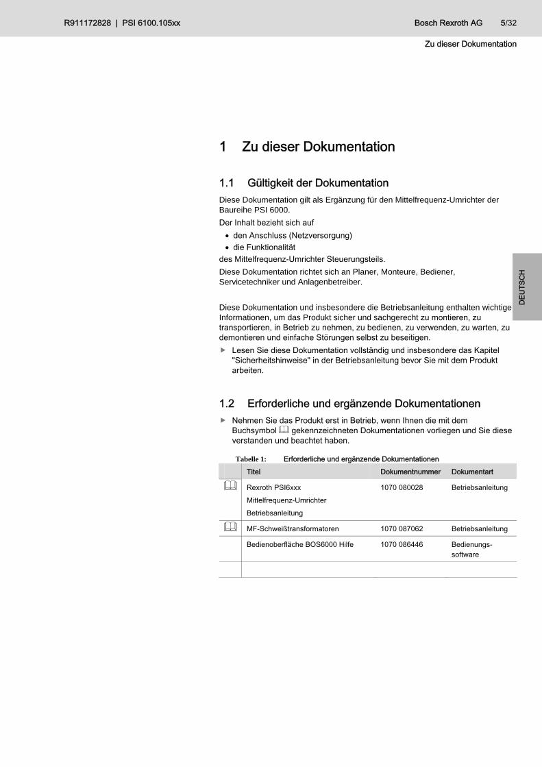
1.1 Gültigkeit der Dokumentation Diese Dokumentation gilt als Ergänzung für den Mittelfrequenz-Umrichter der Baureihe PSI 6000.
Der Inhalt bezieht sich auf den Anschluss (Netzversorgung) die Funktionalität
des Mittelfrequenz-Umrichter Steuerungsteils. Diese Dokumentation richtet sich an Planer, Monteure, Bediener, Servicetechniker und Anlagenbetreiber. Diese Dokumentation und insbesondere die Betriebsanleitung enthalten wichtige Informationen, um das Produkt sicher und sachgerecht zu montieren, zu transportieren, in Betrieb zu nehmen, zu bedienen, zu verwenden, zu warten, zu demontieren und einfache Störungen selbst zu beseitigen. Lesen Sie diese Dokumentation vollständig und insbesondere das Kapitel
"Sicherheitshinweise" in der Betriebsanleitung bevor Sie mit dem Produkt arbeiten.
1.2 Erforderliche und ergänzende Dokumentationen Nehmen Sie das Produkt erst in Betrieb, wenn Ihnen die mit dem
Buchsymbol gekennzeichneten Dokumentationen vorliegen und Sie diese verstanden und beachtet haben.
Tabelle 1: Erforderliche und ergänzende Dokumentationen Titel Dokumentnummer Dokumentart
Rexroth PSI6xxx Mittelfrequenz-Umrichter Betriebsanleitung
1070 080028 Betriebsanleitung
MF-Schweißtransformatoren 1070 087062 Betriebsanleitung
Bedienoberfläche BOS6000 Hilfe 1070 086446 Bedienungs-software

6/32 Bosch Rexroth AG R911172828 | PSI 6100.105xx
Zu dieser Dokumentation
1.3 Darstellung von Informationen Damit Sie mit dieser Dokumentation schnell und sicher mit Ihrem Produkt arbeiten können, werden einheitliche Sicherheitshinweise, Symbole, Begriffe und Abkürzungen verwendet. Zum besseren Verständnis sind diese in den folgenden Abschnitten erklärt.
1.3.1 Sicherheitshinweise Die Sicherheitshinweise sehen Sie bitte unter Tab. 1: Erforderliche und ergänzende Dokumentationen Rexroth PSI6xxx Mittelfrequenz-Umrichter Betriebsanleitung nach.
1.3.2 Symbole
Die folgenden Symbole kennzeichnen Hinweise, die nicht sicherheitsrelevant sind, jedoch die Verständlichkeit der Dokumentation erhöhen.
Tabelle 2: Bedeutung der Symbole Symbol Bedeutung
Wenn diese Information nicht beachtet wird, kann das Produkt nicht optimal genutzt bzw. betrieben werden.
einzelner, unabhängiger Handlungsschritt
1. 2. 3.
nummerierte Handlungsanweisung: Die Ziffern geben an, dass die Handlungsschritte aufeinander folgen.
1.3.3 Bezeichnungen In dieser Dokumentation werden folgende Bezeichnungen verwendet:
Tabelle 3: Bezeichnungen Bezeichnung Bedeutung
BOS 6000 Bedienoberfläche Schweißen
PSG xxxx Mittelfrequenz-Schweißtransformator 1000Hz
1.3.4 Abkürzungen
Die in dieser Dokumentation verwendeten Abkürzungen sehen Sie bitte unter Tab. 1: Erforderliche und ergänzende Dokumentationen Rexroth PSI6xxx Mittelfrequenz-Umrichter Betriebsanleitung nach.

R911172828 | PSI 6100.105xx Bosch Rexroth AG 7/32
Sicherheitshinweise
DEU
TSC
H
2 Sicherheitshinweise Dieses Kapitel enthält wichtige Informationen zum sicheren Umgang mit dem beschriebenen Produkt. Die Sicherheitshinweise sehen Sie bitte unter Tab. 1: Erforderliche und ergänzende Dokumentationen Rexroth PSI6xxx Mittelfrequenz-Umrichter Betriebsanleitung nach.
3 Allgemeine Hinweise vor Sachschäden und Produktschäden
Allgemeine Hinweise vor Sachschäden und Produktschäden sehen Sie bitte unter Tab. 1: Erforderliche und ergänzende Dokumentationen Rexroth PSI6xxx Mittelfrequenz-Umrichter Betriebsanleitung nach.
4 Lieferumfang Den Lieferumfang sehen Sie bitte unter Tab. 1: Erforderliche und ergänzende Dokumentationen Rexroth PSI6xxx Mittelfrequenz-Umrichter Betriebsanleitung nach.
8/32 Bosch Rexroth AG R911172828 | PSI 6100.105xx
Anschlussplan
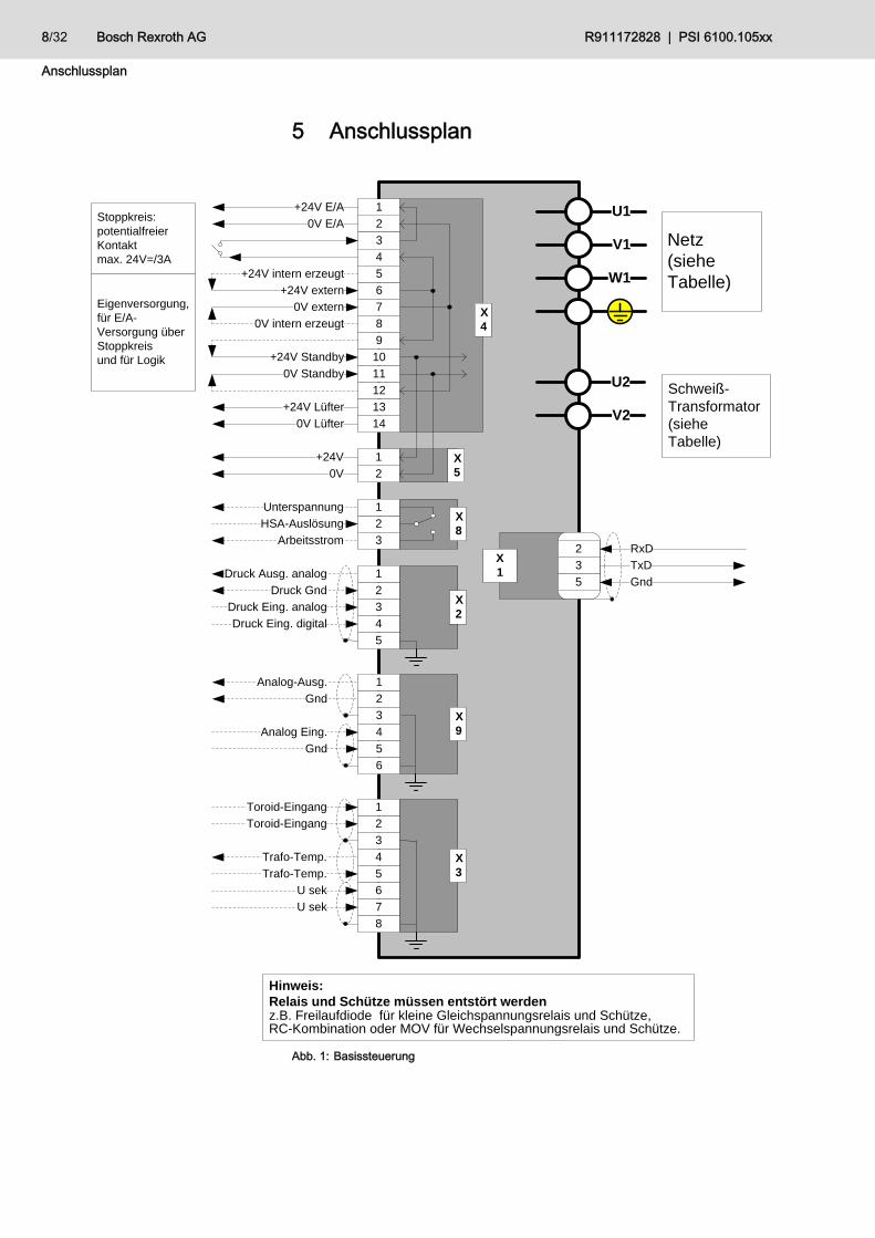
5 Anschlussplan
2Toroid-Eingang
1Toroid-Eingang
3
X3
4Trafo-Temp.
6
5Trafo-Temp.
7
U sek
8
U sek
2Gnd
1Analog-Ausg.
3 X94Analog Eing.
6
5Gnd
2Druck Gnd
1Druck Ausg. analog
3Druck Eing. analogX2
4Druck Eing. digital
5
2HSA-Auslösung
1Unterspannung
3Arbeitsstrom
X8
Netz (siehe Tabelle)
Schweiß-Transformator(siehe Tabelle)
Hinweis:Relais und Schütze müssen entstört werdenz.B. Freilaufdiode für kleine Gleichspannungsrelais und Schütze,RC-Kombination oder MOV für Wechselspannungsrelais und Schütze.
Stoppkreis:potentialfreier Kontaktmax. 24V=/3A
Eigenversorgung,für E/A-Versorgung über Stoppkreisund für Logik
U1
V1
W1
U2
V2
3 TxD
5 Gnd
2 RxDX1
20V
1+24V X5
20V E/A
3
4
1+24V E/A
6+24V extern
70V extern
80V intern erzeugt
5+24V intern erzeugt
10
11
12
9
140V Lüfter
13+24V Lüfter
X4
+24V Standby
0V Standby
Abb. 1: Basissteuerung

R911172828 | PSI 6100.105xx Bosch Rexroth AG 9/32
Anschlussplan
DEU
TSC
H
E 09Parität
E 10Überdruck-Kontakt
E 11Zündung ein, extern
E 08Programmanwahl_128
E 13Ext. Stromzeitabbruch
+24V
+24V
E 12NBS-Freigabe
X13
A 00Magnetventil
A 01
A 02
A 03
A 04
A 05
A 06
A 07
X11
+24V
0 V
+24V
0 V
X10
Bei Betrieb mit internem Netzteil Brücken von X4.1 und X4.2 nach X10.3 und X10.4
Bei Betrieb mit eigenem Netzteil ohne Brücken
E 14
E 15
E16
E17
E 18
E 19
E 20
+24V
X12
E01Start
E 02Programmanwahl_01
E 03Programmanwahl_02
E 05Programmanwahl_08
E 06Programmanwahl_16
E 07Programmanwahl_64
E 04Programmanwahl_04
Fortschaltkontakt
NBS-Anfrage
Bereit Steuerteil
Schweißfehler
Mit Zündung
Ohne Überwachung
Fräs-Anfrage
Fehler rücksetzen
Fehler rücksetzen mit FK
Fehler rücksetzen m. Ablaufwiederholg.
Quittung, Elektrodenfräsen
Quittung, Elektrodenwechsel
Schweißkreis Rückmeldung
Frei
A 08
A 09
A 10
A 11
A 12
0V
Maximale Standmenge
Frei programmierbarer Ausgang 1
Schweißkreis Freischaltung
Warnung
Vorwarnung
Abb. 2: Ein-/Ausgangsbaugruppe

10/32 Bosch Rexroth AG R911172828 | PSI 6100.105xx
Anschlussplan
20V E/A
3
4
1+24V E/A
6+24V extern
70V extern
8
5
10
11
12
9
140V Lüfter
13+24V Lüfter
X4
+24V Standby
0V Standby
Stopp
InterneSpannungs- erzeugung
+24V
0V
0V
+24V
InterneLogik0V
+24V
InterneSpannungs- erzeugung
Stoppkreis:potentialfreier KontaktBelastung 24V=/3A
E/A-Feld Versorgung über Stoppkreis
Logik Versorgung von extern
Variante 2
20V E/A
3
4
1+24V E/A
6+24V extern
70V extern
8
5
10
11
12
9
140V Lüfter
13+24V Lüfter
X4
+24V Standby
0V Standby
Stopp
InterneSpannungs- erzeugung
+24V
0V
0V
+24V
InterneLogik0V
+24V
InterneSpannungs- erzeugung
Stoppkreis:potentialfreier KontaktBelastung 24V=/3A
Eigenversorgung für E/A-Feld über Stoppkreis
Logik Versorgung von Standby - Spannung
Variante 3
20V E/A
3
4
1+24V E/A
6+24V extern
70V extern
8
5
10
11
12
9
140V Lüfter
13+24V Lüfter
X4
+24V Standby
0V Standby
Stopp
InterneSpannungs- erzeugung
+24V
0V
0V
+24V
InterneLogik0V
+24V
InterneSpannungs- erzeugung
Stoppkreis:potentialfreier KontaktBelastung 24V=/3A
Externe Versorgung für E/A-Feld über Stoppkreis
Logik Versorgung von Standby - Spannung
Variante 4
Abb. 3: Anschlussbeispiele

R911172828 | PSI 6100.105xx Bosch Rexroth AG 11/32
Anschlussplan
DEU
TSC
H
Abb. 4: Netzanschluss
12/32 Bosch Rexroth AG R911172828 | PSI 6100.105xx
Ein/Ausgangsfeld
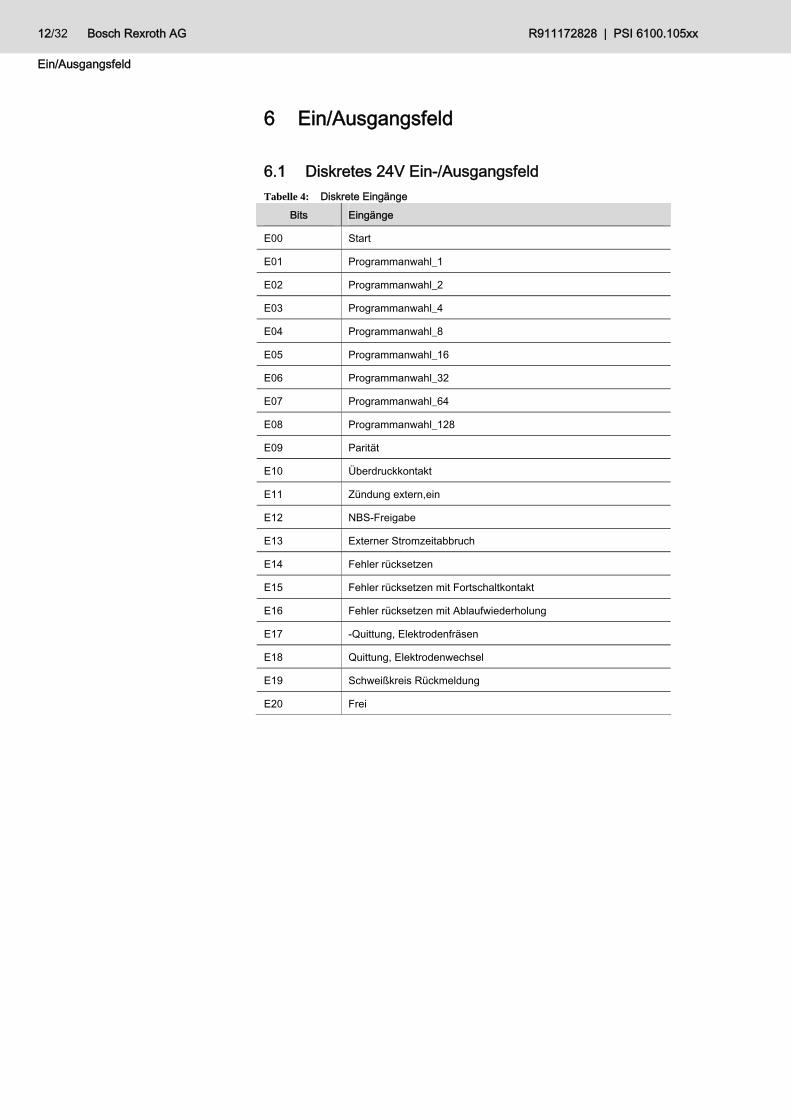
6 Ein/Ausgangsfeld
6.1 Diskretes 24V Ein-/Ausgangsfeld Tabelle 4: Diskrete Eingänge
Bits Eingänge
E00 Start
E01 Programmanwahl_1
E02 Programmanwahl_2
E03 Programmanwahl_4
E04 Programmanwahl_8
E05 Programmanwahl_16
E06 Programmanwahl_32
E07 Programmanwahl_64
E08 Programmanwahl_128
E09 Parität
E10 Überdruckkontakt
E11 Zündung extern,ein
E12 NBS-Freigabe
E13 Externer Stromzeitabbruch
E14 Fehler rücksetzen
E15 Fehler rücksetzen mit Fortschaltkontakt
E16 Fehler rücksetzen mit Ablaufwiederholung
E17 -Quittung, Elektrodenfräsen
E18 Quittung, Elektrodenwechsel
E19 Schweißkreis Rückmeldung
E20 Frei

R911172828 | PSI 6100.105xx Bosch Rexroth AG 13/32
Ein/Ausgangsfeld
DEU
TSC
H
Tabelle 5: Diskrete Ausgänge Bits Ausgänge
A00 Magnetventil
A01 Fortschaltkontakt (FK)
A02 NBS-Anfrage
A03 Bereit Steuerteil
A04 Schweißfehler
A05 Mit Zündung
A06 Ohne Überwachung
A07 Fräsanfrage
A08 Vorwarnung
A09 Maximale Standmenge
A10 Frei programmierbarer Ausgang 1
A11 Schweißkreis Freigabe
A12 Warnung
6.2 Sonstige Ein- /Ausgänge: Tabelle 6: Sonstige Eingänge Eingänge
KSR
Digitale Druckrückmeldung
Transformatortemperatur
Tabelle 7: Sonstige Ausgänge Ausgänge
Analoger Druckausgang
14/32 Bosch Rexroth AG R911172828 | PSI 6100.105xx
Merkmale
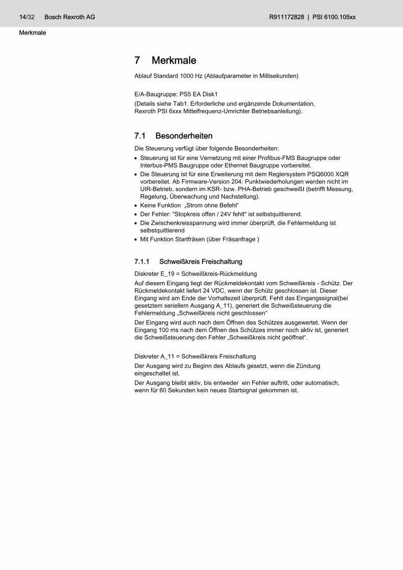
7 Merkmale Ablauf Standard 1000 Hz (Ablaufparameter in Millisekunden) E/A-Baugruppe: PS5 EA Disk1 (Details siehe Tab1. Erforderliche und ergänzende Dokumentation, Rexroth PSI 6xxx Mittelfrequenz-Umrichter Betriebsanleitung).
7.1 Besonderheiten Die Steuerung verfügt über folgende Besonderheiten: Steuerung ist für eine Vernetzung mit einer Profibus-FMS Baugruppe oder
Interbus-PMS Baugruppe oder Ethernet Baugruppe vorbereitet. Die Steuerung ist für eine Erweiterung mit dem Reglersystem PSQ6000 XQR
vorbereitet. Ab Firmware-Version 204: Punktwiederholungen werden nicht im UIR-Betrieb, sondern im KSR- bzw. PHA-Betrieb geschweißt (betrifft Messung, Regelung, Überwachung und Nachstellung).
Keine Funktion „Strom ohne Befehl“ Der Fehler: "Stopkreis offen / 24V fehlt" ist selbstquittierend. Die Zwischenkreisspannung wird immer überprüft, die Fehlermeldung ist
selbstquittierend Mit Funktion Startfräsen (über Fräsanfrage )
7.1.1 Schweißkreis Freischaltung
Diskreter E_19 = Schweißkreis-Rückmeldung Auf diesem Eingang liegt der Rückmeldekontakt vom Schweißkreis - Schütz. Der Rückmeldekontakt liefert 24 VDC, wenn der Schütz geschlossen ist. Dieser Eingang wird am Ende der Vorhaltezeit überprüft. Fehlt das Eingangssignal(bei gesetztem seriellem Ausgang A_11), generiert die Schweißsteuerung die Fehlermeldung „Schweißkreis nicht geschlossen“ Der Eingang wird auch nach dem Öffnen des Schützes ausgewertet. Wenn der Eingang 100 ms nach dem Öffnen des Schützes immer noch aktiv ist, generiert die Schweißsteuerung den Fehler „Schweißkreis nicht geöffnet“. Diskreter A_11 = Schweißkreis Freischaltung Der Ausgang wird zu Beginn des Ablaufs gesetzt, wenn die Zündung eingeschaltet ist. Der Ausgang bleibt aktiv, bis entweder ein Fehler auftritt, oder automatisch, wenn für 60 Sekunden kein neues Startsignal gekommen ist.

R911172828 | PSI 6100.105xx Bosch Rexroth AG 15/32
Statuscodes
DEU
TSC
H
8 Statuscodes Bei diesem Typ sind keine allgemeinen Statuscodes vorhanden.

16/32 Bosch Rexroth AG R911172828 | PSI 6100.105xx
Ablaufdiagramme
9 Ablaufdiagramme Bei diesem Typ sind keine allgemeinen Ablaufdiagramme vorhanden.
R911172828 | PSI 6100.105xx Bosch Rexroth AG 17/32
Contents
ENG
LISH
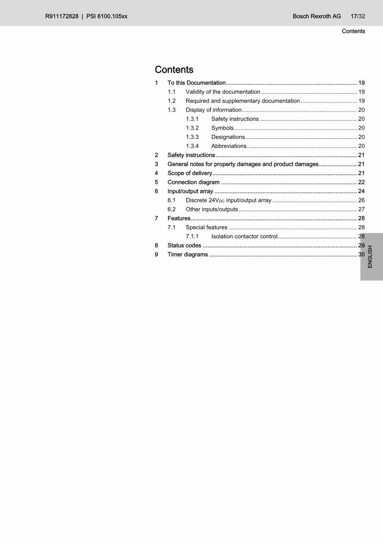
Contents 1 To this Documentation............................................................................... 19
1.1 Validity of the documentation ........................................................... 19 1.2 Required and supplementary documentation................................... 19 1.3 Display of information....................................................................... 20
1.3.1 Safety instructions ............................................................ 20 1.3.2 Symbols............................................................................ 20 1.3.3 Designations..................................................................... 20 1.3.4 Abbreviations.................................................................... 20
2 Safety instructions ..................................................................................... 21 3 General notes for property damages and product damages....................... 21 4 Scope of delivery....................................................................................... 21 5 Connection diagram .................................................................................. 22 6 Input/output array ...................................................................................... 24
6.1 Discrete 24VDC input/output array .................................................... 26 6.2 Other inputs/outputs......................................................................... 27
7 Features.................................................................................................... 28 7.1 Special features ............................................................................... 28
7.1.1 Isolation contactor control................................................. 28 8 Status codes ............................................................................................. 29 9 Timer diagrams ......................................................................................... 30

18/32 Bosch Rexroth AG R911172828 | PSI 6100.105xx
Contents
R911172828 | PSI 6100.105xx Bosch Rexroth AG 19/32
To this Documentation
ENG
LISH
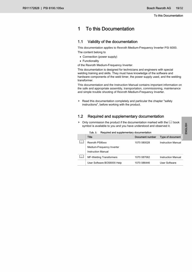
1 To this Documentation
1.1 Validity of the documentation This documentation applies to Rexroth Medium-Frequency Inverter PSI 6000.
The content belong to Connection (power supply) Functionality
of the Rexroth Medium-Frequency Inverter. This documentation is designed for technicians and engineers with special welding training and skills. They must have knowledge of the software and hardware components of the weld timer, the power supply used, and the welding transformer. This documentation and the Instruction Manual contains important information on the safe and appropriate assembly, transportation, commissioning, maintenance and simple trouble shooting of Rexroth Medium-Frequency Inverter.
Read this documentation completely and particular the chapter "safety instructions", before working with the product.
1.2 Required and supplementary documentation Only commission the product if the documentation marked with the book
symbol is available to you and you have understood and observed it.
Tab. 1: Required and supplementary documentation Title Document number Type of document
Rexroth PSI6xxx Medium-Frequency Inverter Instruction Manual
1070 080028 Instruction Manual
MF-Welding Transformers 1070 087062 Instruction Manual
User Software BOS6000 Help 1070 086446 User Software

20/32 Bosch Rexroth AG R911172828 | PSI 6100.105xx
To this Documentation
1.3 Display of information In order to enable you to work with your product in a fast and safe way, uniform Safety instructions, symbols, terms and abbreviations are used. For a better understanding they are explained in the following sections.
1.3.1 Safety instructions
The Safety instructions please look up in Tab. 1: Required and supplementary documentation Rexroth PSI6xxx Medium-Frequency Inverter Instruction Manual.
1.3.2 Symbols The following symbols mark notes that are not safety-relevant but increase the understanding of the documentation.
Tab. 2: Meaning of the Symbols Symbol Meaning
If this information is disregarded, the product cannot be used and or operated to the optimum extent.
Single, independent step
1. 2. 3.
Numbered step: The numbers specify that the Steps are completed one after the other.
1.3.3 Designations This documentation uses the following designations:
Tab. 3: Designation Designation Meaning
BOS 6000 Bedienoberfläche Schweißen (Welding Software)
PSG xxxx Medium-Frequency Welding Transformer 1000Hz
1.3.4 Abbreviations
The in this documentation used abbreviations please look in Tab. 1: Required and supplementary documentation Rexroth PSI6xxx Medium-Frequency Inverter Instruction Manual.

R911172828 | PSI 6100.105xx Bosch Rexroth AG 21/32
Safety instructions
ENG
LISH
2 Safety instructions The Safety instructions please look in Tab. 1: Required and supplementary documentation Rexroth PSI6xxx Medium-Frequency Inverter Instruction Manual.
3 General notes for property damages and product damages
General notes for property damages and product damages please look in Tab. 1: Required and supplementary documentation Rexroth PSI6xxx Medium-Frequency Inverter Instruction Manual.
4 Scope of delivery
The scope of delivery please look up in Tab. 1: Required and supplementary documentationRexroth PSI6xxx Medium-Frequency Inverter Instruction Manual.

22/32 Bosch Rexroth AG R911172828 | PSI 6100.105xx
Connection diagram
5 Connection diagram
2Toroid input
1Toroid input
3
X3
4Transformertemp.
6
5Transformertemp.
7
U sek
8
U sek
2Gnd
1Analog output
3 X94Analog input
6
5Gnd
2Pressure Gnd
1Pressure outp. analog
3Pressure inp. analogX2
4Pressure inp. digital
5
2+24V (main switch release)
1Undervoltage Release
3Shunt release
X8
Mains(see table)
Welding-Transformer(see table)
Note:Relay and contactors require RFI suppressione.g. free wheeling diode for small relays and contactors
Stop circuit:Floating contactmax. load:24VDC / 3A
Internal power supply for I/O -Board with Stop circuit
U1
V1
W1
U2
V2
3 TxD
5 Gnd
2 RxDX1
20VDC
124VDC X5
20VDC I/O
3
4
124VDC I/O
624VDC external
70VDC external
80VDC internal
524VDC internal
10
11
12
9
140VDC Fan
1324VDC Fan
X4
24VDC standby
0VDC standby
Fig. 1: Inverter control

R911172828 | PSI 6100.105xx Bosch Rexroth AG 23/32
Connection diagram
ENG
LISH
E 09Parity
E 10Pressure Contact
E 11Weld / No Weld, external
E 08Program Select_128
E 13External Weld Stop
24V
24V
E 12NBS Enable
X13
A 00Magnet valve
A 01
A 02
A 03
A 04
A 05
A 06
A 07
X11
24V
0 V
24V
0 V
X10
When using an internal power supply, bridge between X4.1 and X4.2 to X10.3 and X10.4
When using an external power supply, work without bridges from X4 to X10.
E 14
E 15
E16
E17
E 18
E 19
E 20
24V
X12
E01Start
E 02Program Select_01
E 03Program Select_02
E 05Program Select_08
E 06Program Select_16
E 07Program Select_64
E 04Program Select_04
Weld Complete
NBS-Allow
Timer Ready
Weld Fault
Weld On
Without monitoring
Tip dress request
Fault Reset
Fault Reset + Weld Complete
Fault Reset + Reweld
Tips have been dressed
Electrodes are replaced
Weld Contactor Closed
Not used
A 08
A 09
A 10
A 11
A 12
0V
End of stepper
Free programmable output 1
Close Weld Contactor
Warning
Prewarning
Fig. 2: I/O board

24/32 Bosch Rexroth AG R911172828 | PSI 6100.105xx
Connection diagram
20V I/O
3
4
124VDC I/O
624VDC external
70VDC external
8
5
10
11
12
9
140VDC Fan
1324VDC Fan
X4
24VDC standby
0VDC standby
Stop
Internal power supply
24VDC
0VDC
0VDC
24VDC
Internal Logic0VDC
24VDC
Internal power supply
Stop circuit:Floating contactmax. load:24VDC / 3A
I/O - Board supply with stop circuit
External logic supply
Option 2
20V I/O
3
4
124VDC I/O
624VDC external
70VDC external
8
5
10
11
12
9
140VDC Fan
1324VDC Fan
X4
24VDC standby
0VDC standby
Stop
Internal power supply
24VDC
0VDC
0VDC
24VDC
Internal Logic0VDC
24VDC
Internal power supplyOption 3
20V I/O
3
4
124VDC I/O
624VDC external
70VDC external
8
5
10
11
12
9
140VDC Fan
1324VDC Fan
X4
24VDC standby
0VDC standby
Stop
Internal power supply
24VDC
0VDC
0VDC
24VDC
Internal Logic0VDC
24VDC
Internal power supplyOption 4
Stop circuit:Floating contactmax. load:24VDC / 3A
Stop circuit:Floating contactmax. load:24VDC / 3A
Internal I/O - Board supply with stop circuit
Logic supply by Standby - Supply
External I/O - Board supply with stop circuit
Logic supply by Standby - Supply
Fig. 1: Connection diagram examples

R911172828 | PSI 6100.105xx Bosch Rexroth AG 25/32
Connection diagram
ENG
LISH
Fig. 2: Mains connection
26/32 Bosch Rexroth AG R911172828 | PSI 6100.105xx
Input/output array
6 Input/output array
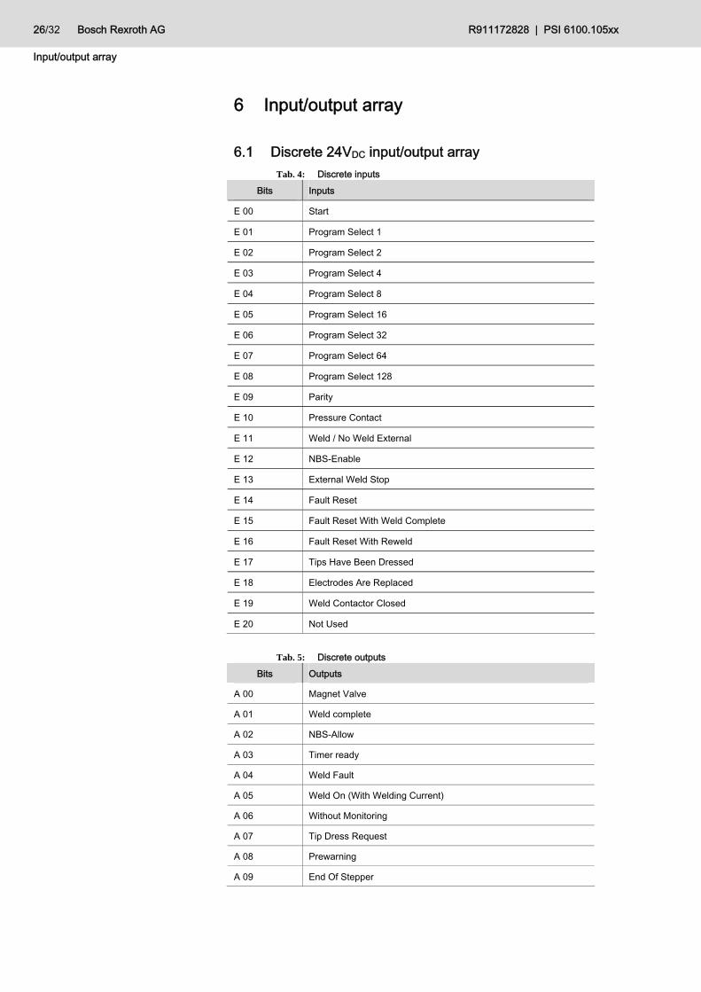
6.1 Discrete 24VDC input/output array Tab. 4: Discrete inputs
Bits Inputs
E 00 Start
E 01 Program Select 1
E 02 Program Select 2
E 03 Program Select 4
E 04 Program Select 8
E 05 Program Select 16
E 06 Program Select 32
E 07 Program Select 64
E 08 Program Select 128
E 09 Parity
E 10 Pressure Contact
E 11 Weld / No Weld External
E 12 NBS-Enable
E 13 External Weld Stop
E 14 Fault Reset
E 15 Fault Reset With Weld Complete
E 16 Fault Reset With Reweld
E 17 Tips Have Been Dressed
E 18 Electrodes Are Replaced
E 19 Weld Contactor Closed
E 20 Not Used
Tab. 5: Discrete outputs
Bits Outputs
A 00 Magnet Valve
A 01 Weld complete
A 02 NBS-Allow
A 03 Timer ready
A 04 Weld Fault
A 05 Weld On (With Welding Current)
A 06 Without Monitoring
A 07 Tip Dress Request
A 08 Prewarning
A 09 End Of Stepper

R911172828 | PSI 6100.105xx Bosch Rexroth AG 27/32
Input/output array
ENG
LISH
Bits Outputs
A 10 Free Programmable Output
A 11 Close Weld Contactor
A 12 Warning
6.2 Other inputs/outputs Tab. 6: Other inputs
Inputs
KSR
Digital pressure feedback
Transformer temperature
Tab. 7: Other outputs
Outputs
Analog pressure output
28/32 Bosch Rexroth AG R911172828 | PSI 6100.105xx
Features
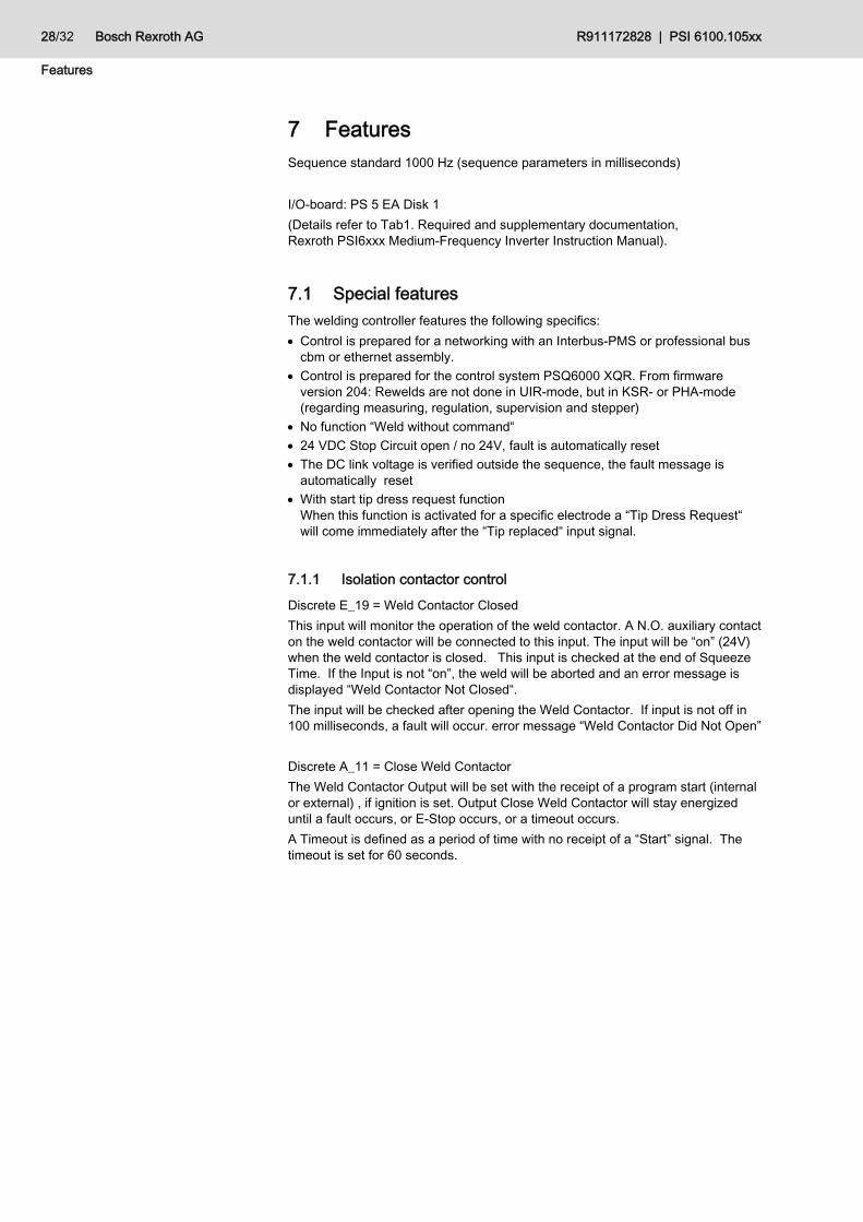
7 Features Sequence standard 1000 Hz (sequence parameters in milliseconds) I/O-board: PS 5 EA Disk 1 (Details refer to Tab1. Required and supplementary documentation, Rexroth PSI6xxx Medium-Frequency Inverter Instruction Manual).
7.1 Special features The welding controller features the following specifics: Control is prepared for a networking with an Interbus-PMS or professional bus
cbm or ethernet assembly. Control is prepared for the control system PSQ6000 XQR. From firmware
version 204: Rewelds are not done in UIR-mode, but in KSR- or PHA-mode (regarding measuring, regulation, supervision and stepper)
No function “Weld without command“ 24 VDC Stop Circuit open / no 24V, fault is automatically reset The DC link voltage is verified outside the sequence, the fault message is
automatically reset With start tip dress request function
When this function is activated for a specific electrode a “Tip Dress Request“ will come immediately after the “Tip replaced“ input signal.
7.1.1 Isolation contactor control Discrete E_19 = Weld Contactor Closed This input will monitor the operation of the weld contactor. A N.O. auxiliary contact on the weld contactor will be connected to this input. The input will be “on” (24V) when the weld contactor is closed. This input is checked at the end of Squeeze Time. If the Input is not “on”, the weld will be aborted and an error message is displayed “Weld Contactor Not Closed“. The input will be checked after opening the Weld Contactor. If input is not off in 100 milliseconds, a fault will occur. error message “Weld Contactor Did Not Open” Discrete A_11 = Close Weld Contactor The Weld Contactor Output will be set with the receipt of a program start (internal or external) , if ignition is set. Output Close Weld Contactor will stay energized until a fault occurs, or E-Stop occurs, or a timeout occurs. A Timeout is defined as a period of time with no receipt of a “Start” signal. The timeout is set for 60 seconds.

R911172828 | PSI 6100.105xx Bosch Rexroth AG 29/32
Status codes
ENG
LISH
8 Status codes There are no status codes available for this type.

30/32 Bosch Rexroth AG R911172828 | PSI 6100.105xx
Timer diagrams
9 Timer diagrams There are no general timer diagrams available for this type.

R911172828 | PSI 6100.105xx Bosch Rexroth AG 31/32
Timer diagrams
ENG
LISH
Notes:
DOK-PS6000-PSI6XXX.105-IT01-D0-PR911172828
Bosch Rexroth AG Electric Drives and Controls P.O. Box 13 57 97803 Lohr, Germany Bgm.-Dr.-Nebel-Str. 2 97816 Lohr, Germany Tel. +49 9352 18 0 Fax +49 9352 18 8400 www.boschrexroth.com/electrics