Rexroth IndraDyn T Synchron-Torquemotor Version 02 Rexroth/Motors/MBT... · Project Planning Manual...
156
Project Planning Manual 298798 Version 02 Rexroth IndraDyn T Synchron-Torquemotor Industrial Hydraulics Electric Drives and Controls Linear Motion and Assembly Technologies Pneumatics Service Automation Mobile Hydraulics
Transcript of Rexroth IndraDyn T Synchron-Torquemotor Version 02 Rexroth/Motors/MBT... · Project Planning Manual...

Project Planning Manual
298798Version 02
Rexroth IndraDyn TSynchron-Torquemotor
IndustrialHydraulics
Electric Drivesand Controls
Linear Motion andAssembly Technologies Pneumatics
ServiceAutomation
MobileHydraulics

Über diese Dokumentation IndraDyn T
Rexroth IndraDyn T
Synchron-Torquemotor
Project Planning Manual
DOK-MOTOR*-MBT********-PR02-EN-P
• 29879802_Book.doc
• Document Number 120-1500-B315-02/EN
This documentation....
• explains product features and applications, technical data as well asconditions and limits for operation.
• provides guidlines for product selection, application, handling andoperation.
Description ReleaseDate
Notes
DOK-MOTOR*-MBT********-PR02-EN-P 06.03 1st edition
Bosch Rexroth AG, 2003
Copying this document, giving it to others and the use or communicationof the contents thereof without express authority, are forbidden. Offendersare liable for the payment of damages. All rights are reserved in the eventof the grand of a patent or the registration of a utility model or design (DIN34-1).
The specified data is for product description purposes only and may notbe deemed to be guaranteed unless expressly confirmed in the contract.All rights are reserved with respect to the content of this documentationand the availability of the product.
Bosch Rexroth AGBgm.-Dr.-Nebel-Str. 2 • D-97816 Lohr a. Main
Telefon +49 (0)93 52 / 40-0 • Tx 68 94 21 • Fax +49 (0)93 52 / 40-48 85
http://www.boschrexroth.com/
Abt. EDM1 (FS)
This document has been printed on chlorine-free bleached paper.
Title
Type of Documentation
Document Typecode
Internal File Reference
Purpose of Documentation
Record of Revisions
Copyright
Validity
Published by
Note
REXROTH IndraDyn T Table of Contents I
Table of Contents
1 Introduction to the Product 1-1
1.1 About this Documentation............................................................................................................. 1-2
Standards................................................................................................................................. 1-3
Additional components............................................................................................................. 1-3
Feedback ................................................................................................................................. 1-3
2 Important directions for use 2-1
2.1 Appropriate use............................................................................................................................. 2-1
Introduction .............................................................................................................................. 2-1
Areas of use and application.................................................................................................... 2-2
2.2 Inappropriate use .......................................................................................................................... 2-2
3 Safety Instructions for Electric Drives and Controls 3-1
3.1 Introduction ................................................................................................................................... 3-1
3.2 Explanations.................................................................................................................................. 3-1
3.3 Hazards by Improper Use ............................................................................................................. 3-2
3.4 General Information ...................................................................................................................... 3-3
3.5 Protection Against Contact with Electrical Parts........................................................................... 3-5
3.6 Protection Against Electric Shock by Protective Low Voltage (PELV) ......................................... 3-6
3.7 Protection Against Dangerous Movements .................................................................................. 3-7
3.8 Protection Against Magnetic and Electromagnetic Fields During Operation andMounting ....................................................................................................................................... 3-9
3.9 Protection Against Contact with Hot Parts .................................................................................. 3-10
3.10 Protection During Handling and Mounting .................................................................................. 3-10
3.11 Battery Safety.............................................................................................................................. 3-11
3.12 Protection Against Pressurized Systems.................................................................................... 3-11
4 Technical Data 4-1
4.1 Definitions ..................................................................................................................................... 4-1
Operating Modes ..................................................................................................................... 4-1
ON time.................................................................................................................................... 4-1
Parameters .............................................................................................................................. 4-2
Operating characteristic ........................................................................................................... 4-3
4.2 Data sheet size 210 ...................................................................................................................... 4-4
Motor characteristic curve MBT210 ......................................................................................... 4-5
4.1 Data sheet size 290 ...................................................................................................................... 4-6
Motor characteristic curve MBT290 ........................................................................................ 4-7
4.2 Data sheet size 360 ...................................................................................................................... 4-8
Motor characteristic curve MBT360 ......................................................................................... 4-9
II Table of Contents REXROTH IndraDyn T
4.3 Data sheet size 450 .................................................................................................................... 4-10
Motor characteristic curve MBT450 ...................................................................................... 4-11
4.4 Data sheet size 530 .................................................................................................................... 4-12
Motor characteristic curve MBT530 ...................................................................................... 4-13
5 Dimension sheet IndraDyn T 5-1
5.1 Dimension sheet size MBT210 ..................................................................................................... 5-2
Electrical connection “SN”........................................................................................................ 5-2
Electrical connection “CN” ....................................................................................................... 5-3
Electrical connection “RN” (dimension sheet in preparation) .................................................. 5-4
Rotor MRT210 ......................................................................................................................... 5-5
Rotor MRT210 mounted .......................................................................................................... 5-6
Stator MST210 electrical connection “SN”............................................................................... 5-7
Stator MST210 electrical connection “CN” .............................................................................. 5-8
Stator MST210 electrical connection “RN” .............................................................................. 5-9
Stator MST210 mounted........................................................................................................ 5-10
Rotor and Stator MBT210 mounted....................................................................................... 5-11
5.2 Dimension sheet size MBT290 ................................................................................................... 5-12
Electrical connection "SN" .................................................................................................... 5-12
Electrical connection "CN" .................................................................................................... 5-13
Electrical connection "RN" (Dimension sheet in preparation)............................................... 5-14
Rotor MRT290 ....................................................................................................................... 5-15
Rotor MRT290 mounted ........................................................................................................ 5-16
Stator MST290 electrical connection "SN" ........................................................................... 5-17
Stator MST290 electrical connection "CN" ........................................................................... 5-18
Stator MST290 electrical connection "RN" ........................................................................... 5-19
Stator MST290 mounted........................................................................................................ 5-20
Rotor and Stator MBT290 mounted....................................................................................... 5-21
5.3 Dimension sheet size MBT360 ................................................................................................... 5-22
Electrical connection "SN" .................................................................................................... 5-22
Electrical connection "CN" .................................................................................................... 5-23
Electrical connection "RN" (Dimension sheet in preparation)............................................... 5-24
Rotor MRT360 ....................................................................................................................... 5-25
Rotor MRT360 mounted ........................................................................................................ 5-26
Stator MST360 electrical connection "SN" ........................................................................... 5-27
Stator MST360 electrical connection "CN" ........................................................................... 5-28
Stator MST360 electrical connection "RN" ........................................................................... 5-29
Stator MST360 mounted, electrical connection "SN" ........................................................... 5-30
Stator MST360 mounted, electrical connection "CN" ........................................................... 5-31
Rotor and Stator MBT360 mounted....................................................................................... 5-32
5.4 Dimension sheet size MBT450 ................................................................................................... 5-33
Electrical connection "SN" .................................................................................................... 5-33
Electrical connection "CN" .................................................................................................... 5-34
Electrical connection "RN" (Dimension sheet in preparation)............................................... 5-35
Rotor MRT450 ....................................................................................................................... 5-36
Rotor MRT450 mounted ........................................................................................................ 5-37

REXROTH IndraDyn T Table of Contents III
Stator MST450 electrical connection "SN" ........................................................................... 5-38
Stator MST450 electrical connection "CN" ........................................................................... 5-39
Stator MST450 electrical connection "RN" ........................................................................... 5-40
Stator MST450 mounted........................................................................................................ 5-41
Rotor and Stator MBT450 mounted....................................................................................... 5-42
5.5 Dimension sheet size MBT530 ................................................................................................... 5-43
Electrical connection "SN" .................................................................................................... 5-43
Electrical connection "CN" .................................................................................................... 5-44
Electrical connection "RN" (Dimension sheet in preparation)............................................... 5-45
Rotor MRT530 ....................................................................................................................... 5-46
Rotor MRT530 mounted ........................................................................................................ 5-47
Stator MST530 electrical connection "SN" ........................................................................... 5-48
Stator MST530 electrical connection "CN" ........................................................................... 5-49
Stator MST530 electrical connection "RN" ........................................................................... 5-50
Stator MST530 mounted, electrical connection "SN" ........................................................... 5-51
Stator MST530 mounted, electrical connection "CN" ........................................................... 5-52
Rotor and Stator MBT530 mounted....................................................................................... 5-53
6 Type Code 6-1
Type code rotor MRT ............................................................................................................... 6-1
Type code stator MST.............................................................................................................. 6-1
6.1 Rotor MRT210............................................................................................................................... 6-3
6.2 Stator MST210 .............................................................................................................................. 6-4
6.3 Rotor MRT290............................................................................................................................... 6-5
6.4 Stator MST290 .............................................................................................................................. 6-5
6.5 Rotor MRT360............................................................................................................................... 6-6
6.6 Stator MST360 .............................................................................................................................. 6-6
6.7 Rotor MRT450............................................................................................................................... 6-7
6.8 Stator MST450 .............................................................................................................................. 6-7
6.9 Rotor MRT530............................................................................................................................... 6-8
6.10 Stator MST530 .............................................................................................................................. 6-8
7 Accessories 7-1
7.1 Mounting ring ................................................................................................................................ 7-1
Construction............................................................................................................................. 7-1
Assignment .............................................................................................................................. 7-2
Handling ................................................................................................................................... 7-2
Mounting ring dimension sheet ................................................................................................ 7-3
SUP-M01-MBT450................................................................................................................... 7-3
SUP-M02-MBT450................................................................................................................... 7-4
SUP-M01-MBT530................................................................................................................... 7-5
SUP-M02-MBT530................................................................................................................... 7-6
SUP-M03-MBT530................................................................................................................... 7-7
8 Connection System 8-1
8.1 Notes............................................................................................................................................. 8-1

IV Table of Contents REXROTH IndraDyn T
Connecting cable ..................................................................................................................... 8-2
8.2 Connection with terminal box........................................................................................................ 8-3
Terminal box ............................................................................................................................ 8-3
8.3 Connection with coupling .............................................................................................................. 8-5
Coupling and connector ........................................................................................................... 8-5
8.4 Sensors ......................................................................................................................................... 8-6
Encoder.................................................................................................................................... 8-6
Temperature sensor................................................................................................................. 8-6
8.5 Motor cooling................................................................................................................................. 8-7
Operating pressure .................................................................................................................. 8-7
9 Application Notes 9-1
9.1 Conditions for Use......................................................................................................................... 9-1
Operation altitude and ambient Temperature.......................................................................... 9-1
9.2 Motor cooling................................................................................................................................. 9-2
Coolants ................................................................................................................................... 9-2
Used materials ......................................................................................................................... 9-3
Coolant temperature ................................................................................................................ 9-3
Operation without liquid coolant............................................................................................... 9-4
9.3 Degree of Protection ..................................................................................................................... 9-4
9.4 Motor temperature control............................................................................................................. 9-5
9.5 Fastening ...................................................................................................................................... 9-7
Stator........................................................................................................................................ 9-7
Rotor ........................................................................................................................................ 9-7
Fixing hole................................................................................................................................ 9-8
9.6 Drive End and Direction of Rotation.............................................................................................. 9-9
9.7 Third-part systems ...................................................................................................................... 9-11
Notes...................................................................................................................................... 9-12
10 Handling and Transport 10-1
10.1 Supplied Condition ...................................................................................................................... 10-1
Factory Inspection.................................................................................................................. 10-1
Inspection by Customer ......................................................................................................... 10-1
Scope of delivery.................................................................................................................... 10-2
10.2 Transport and Storage ................................................................................................................ 10-3
Transport................................................................................................................................ 10-4
Storage................................................................................................................................... 10-4
11 Installation 11-1
11.1 Safety .......................................................................................................................................... 11-1
11.2 Mounting ring .............................................................................................................................. 11-1
11.3 Mechanical installation ................................................................................................................ 11-2
Preparation............................................................................................................................. 11-2
Assembly................................................................................................................................ 11-2
11.4 Electrical Connection .................................................................................................................. 11-4
11.5 Coolant connection ..................................................................................................................... 11-4

REXROTH IndraDyn T Table of Contents V
12 Operating torque motors 12-1
12.1 Commissioning............................................................................................................................ 12-1
Preparation............................................................................................................................. 12-1
Execution ............................................................................................................................... 12-1
12.2 Deactivation ................................................................................................................................ 12-2
12.3 Dismantling ................................................................................................................................. 12-2
12.4 Maintenance................................................................................................................................ 12-3
Measures ............................................................................................................................... 12-3
Coolant supply ....................................................................................................................... 12-3
12.5 Troubleshooting .......................................................................................................................... 12-4
Excess Temperature of Motor Housing ................................................................................. 12-5
High motor temperature values, but housing temperature is normal .................................... 12-5
Motor or machine generates vibrations ................................................................................. 12-6
Specified position is not attained ........................................................................................... 12-6
13 Service & Support 13-1
13.1 Helpdesk ..................................................................................................................................... 13-1
13.2 Service-Hotline............................................................................................................................ 13-1
13.3 Internet ........................................................................................................................................ 13-1
13.4 Vor der Kontaktaufnahme... - Before contacting us.................................................................... 13-1
13.5 Kundenbetreuungsstellen - Sales & Service Facilities ............................................................... 13-2
14 Index 14-1

VI Table of Contents REXROTH IndraDyn T

REXROTH IndraDyn T Introduction to the Product 1-1
1 Introduction to the ProductThe synchronous torque motor series IndraDyn T of REXROTH consist ofthe units stator MST and rotor MRT. The stator comes with a laminatedcore with multipolar winding, a liquid cooling jacket and a connectingcable. The rotor is fitted with permanent magnets.
RotorStator
MBT1.eps
(1): Stator MST (2): Rotor MRTFig. 1-1: IndraDyn T units
Synchronous torque motors IndraDyn T have a high torque withminimized residual ripple. This motors are extremely suited for compactdirect drives for rotary tables.
The combination with digital control devices from the INDRADRIVE, DIAXor ECODRIVE series forms intelligent drive solutions with high powerdensity and open functions.
The following diagram provides an overview of the torque spectrum of thesynchronous torque motors IndraDyn T from REXROTH.
240105
4700
2100
3250
1400
1900
8751150
575 500 240
1800
810
1150
525700
350300
150
2700
1200
250 120
1800
800
1200
540
900
350 460220
100 500
500
1000
1500
2000
2500
3000
3500
4000
4500
5000
M[N
m]
210290360450530
A
B
C
D
E
R
210
290
360
450
530
Dauerdrehmoment MN
Rated torque MN
Maximaldrehmoment Mmax
Maximumtorque Mmax
Motorbaugröße / Motor size
Fig. 1-2: IndraDyn T overview

1-2 Introduction to the Product REXROTH IndraDyn T
1.1 About this Documentation
Document structureThis documentation includes safety instructions, technical data andoperating instructions. The following setup provides an overview of thecontents of this documentation.
Chapter Title
1 Introduction Introduction to the product andnotes
2 Important Instructions on Use
3 SafetyImportant safety instructions
4 Technical data
5 Dimension sheetsProduct
description
6 Type Code
7 Accessories
8 Connection System
for planners andprojectors
9 Application Notes
10 Handling & Transport
11 Installation
PracticeOperating andmaintenance
personnel
12 Operation
13 Service & Support
14 Index Additional information
Fig. 1-3: Chapter structure
ModificationsThe following list shows the modifications as compared with the previousversion DOK-MOTOR*-MBT********-PR01 -EN-P
Where? What?
Chapter 1 Revised and updated
Chapter 4-14Update of technical data, dimension sheets and typecodesUpdate content and chapter order
Fig. 1-4: Modifications

REXROTH IndraDyn T Introduction to the Product 1-3
Additional documentationProjecting drive systems with IndraDyn T possibly requires additionaldocumentation about the used equipment. Rexroth provides all productdocumentation on CD in PDF-format. The documentation on CD as awhole is not necessary for projecting individual systems.
Note: All documentation on the CD are also available as printedversion. You can order the necessary documentation overyour local Rexroth representation.
Material no.: Title / description
00281882 -Productdocumentation Electric Drives and Controls Version xx 1)
DOK-GENRL-CONTR*DRIVE-GNxx-EN-D650
1) The index (e.g. ..0.02-...) identifies the version of the documentation.
Fig. 1-5: Additional documentation
StandardsThis documentation refers to German, European and internationaltechnical standards. Documents and sheets on standards are subject tocopyright protection and may not be passed on to third parties by Rexroth.If necessary, please address the authorized sales outlets or, in Germany,directly to:
BEUTH Verlag GmbHBurggrafenstrasse 610787 Berlin
Phone +49-(0)30-26 01-22 60, Fax +49-(0)30-26 01-12 60Internet: http://www.din.de/beuth [email protected]
Additional componentsDocumentations for external systems, which are connected to BoschRexroth components, are not included in the scope of delivery and mustbe ordered directly from the particular manufacturers.
For information of the manufacturers see chapter “Application note”.
FeedbackYour experiences are an essential part of the process of improving bothproduct and documentation.
Please do not hesitate to inform us of any mistakes you detect in thisdocumentation or of any modifications you might desire. We appreciateyour feedback.
Please send your remarks to:
Rexroth Indramat GmbHDep. EDM1Bürgermeister-Dr.-Nebel-Strasse 2D-97816 Lohr, Germany
Fax +49 (0) 93 52 / 40-43 80

1-4 Introduction to the Product REXROTH IndraDyn T
REXROTH IndraDyn T Important directions for use 2-1
2 Important directions for use
2.1 Appropriate use
IntroductionBosch Rexroth products represent state-of-the-art developments andmanufacturing. They are tested prior to delivery to ensure operating safetyand reliability.
The products may only be used in the manner that is defined asappropriate. If they are used in an inappropriate manner, then situationscan develop that may lead to property damage or injury to personnel.
Note: Bosch Rexroth, as manufacturer, is not liable for any damagesresulting from inappropriate use. In such cases, the guaranteeand the right to payment of damages resulting frominappropriate use are forfeited. The user alone carries allresponsibility of the risks.
Before using Bosch Rexroth products, make sure that all the pre-requisites for appropriate use of the products are satisfied:
• Personnel that in any way, shape or form uses our products must firstread and understand the relevant safety instructions and be familiarwith appropriate use.
• If the product takes the form of hardware, then they must remain intheir original state, in other words, no structural changes are permitted.It is not permitted to decompile software products or alter sourcecodes.
• Do not mount damaged or faulty products or use them in operation.
• Make sure that the products have been installed in the mannerdescribed in the relevant documentation.
2-2 Important directions for use REXROTH IndraDyn T
Areas of use and applicationRexroth IndraDyn T motors are designed to be used as rotary drivemotors in machines.
Several types of motors with differing drive power and different interfacesare available for application-specific uses.
Control and monitoring of the motors may require additional sensors andactors.
Note: The motors may only be used with the accessories and partsspecified in this document. If a component has not beenspecifically named, then it may not be either mounted orconnected. The same applies to cables and lines.
Operation is only permitted in the specified configurations andcombinations of components using the software and firmwareas specified in the relevant function descriptions.
Every drive controller has to be programmed before starting it up, makingit possible for the motor to execute the specific functions of an application.
The motors may only be operated under the assembly, installation andambient conditions as described here (temperature, system of protection,humidity, EMC requirements, etc.) and in the position specified.
2.2 Inappropriate use
Inappropriate use is defined as using the motors outside of the above-referenced areas of application or under operating conditions other thandescribed in the document and the technical data specified.
IndraDyn T motors may not be used if
• they are subject to operating conditions that do not meet the abovespecified ambient conditions. This includes, for example, operationunder water, in the case of extreme temperature fluctuations orextremely high maximum temperatures or if
• Bosch Rexroth has not specifically released them for that intendedpurpose. Please note the specifications outlined in the general SafetyGuidelines!
REXROTH IndraDyn T Safety Instructions for Electric Drives and Controls 3-1
3 Safety Instructions for Electric Drives and Controls
3.1 Introduction
Read these instructions before the initial startup of the equipment in orderto eliminate the risk of bodily harm or material damage. Follow thesesafety instructions at all times.
Do not attempt to install or start up this equipment without first reading alldocumentation provided with the product. Read and understand thesesafety instructions and all user documentation of the equipment prior toworking with the equipment at any time. If you do not have the userdocumentation for your equipment, contact your local Bosch Rexrothrepresentative to send this documentation immediately to the person orpersons responsible for the safe operation of this equipment.
If the equipment is resold, rented or transferred or passed on to others,then these safety instructions must be delivered with the equipment.
WARNING
Improper use of this equipment, failure to followthe safety instructions in this document ortampering with the product, including disablingof safety devices, may result in materialdamage, bodily harm, electric shock or evendeath!
3.2 Explanations
The safety instructions describe the following degrees of hazardseriousness in compliance with ANSI Z535. The degree of hazardseriousness informs about the consequences resulting from non-compliance with the safety instructions.
Warning symbol with signalword
Degree of hazard seriousness accordingto ANSI
DANGER
Death or severe bodily harm will occur.
WARNING
Death or severe bodily harm may occur.
CAUTION
Bodily harm or material damage may occur.
Fig. 3-1: Hazard classification (according to ANSI Z535)

3-2 Safety Instructions for Electric Drives and Controls REXROTH IndraDyn T
3.3 Hazards by Improper Use
DANGER
High voltage and high discharge current!Danger to life or severe bodily harm by electricshock!
DANGER
Dangerous movements! Danger to life, severebodily harm or material damage byunintentional motor movements!
WARNING
High electrical voltage due to wrongconnections! Danger to life or bodily harm byelectric shock!
WARNING
Health hazard for persons with heartpacemakers, metal implants and hearing aids inproximity to electrical equipment!
CAUTION
Surface of machine housing could be extremelyhot! Danger of injury! Danger of burns!
CAUTION
Risk of injury due to improper handling! Bodilyharm caused by crushing, shearing, cutting andmechanical shock or incorrect handling ofpressurized systems!
CAUTION
Risk of injury due to incorrect handling ofbatteries!

REXROTH IndraDyn T Safety Instructions for Electric Drives and Controls 3-3
3.4 General Information
• Bosch Rexroth AG is not liable for damages resulting from failure toobserve the warnings provided in this documentation.
• Read the operating, maintenance and safety instructions in yourlanguage before starting up the machine. If you find that you cannotcompletely understand the documentation for your product, please askyour supplier to clarify.
• Proper and correct transport, storage, assembly and installation aswell as care in operation and maintenance are prerequisites foroptimal and safe operation of this equipment.
• Only persons who are trained and qualified for the use and operationof the equipment may work on this equipment or within its proximity.
• The persons are qualified if they have sufficient knowledge of theassembly, installation and operation of the equipment as well as anunderstanding of all warnings and precautionary measures noted inthese instructions.
• Furthermore, they must be trained, instructed and qualified toswitch electrical circuits and equipment on and off in accordancewith technical safety regulations, to ground them and to mark themaccording to the requirements of safe work practices. They musthave adequate safety equipment and be trained in first aid.
• Only use spare parts and accessories approved by the manufacturer.
• Follow all safety regulations and requirements for the specificapplication as practiced in the country of use.
• The equipment is designed for installation in industrial machinery.
• The ambient conditions given in the product documentation must beobserved.
• Use only safety features and applications that are clearly and explicitlyapproved in the Project Planning Manual.For example, the following areas of use are not permitted: constructioncranes, elevators used for people or freight, devices and vehicles totransport people, medical applications, refinery plants, transport ofhazardous goods, nuclear applications, applications sensitive to highfrequency, mining, food processing, control of protection equipment(also in a machine).
• The information given in the documentation of the product with regardto the use of the delivered components contains only examples ofapplications and suggestions.The machine and installation manufacturer must
• make sure that the delivered components are suited for hisindividual application and check the information given in thisdocumentation with regard to the use of the components,
• make sure that his application complies with the applicable safetyregulations and standards and carry out the required measures,modifications and complements.
• Startup of the delivered components is only permitted once it is surethat the machine or installation in which they are installed complieswith the national regulations, safety specifications and standards of theapplication.

3-4 Safety Instructions for Electric Drives and Controls REXROTH IndraDyn T
• Operation is only permitted if the national EMC regulations for theapplication are met.The instructions for installation in accordance with EMC requirementscan be found in the documentation "EMC in Drive and ControlSystems".The machine or installation manufacturer is responsible forcompliance with the limiting values as prescribed in the nationalregulations.
• Technical data, connections and operational conditions are specified inthe product documentation and must be followed at all times.

REXROTH IndraDyn T Safety Instructions for Electric Drives and Controls 3-5
3.5 Protection Against Contact with Electrical Parts
Note: This section refers to equipment and drive components withvoltages above 50 Volts.
Touching live parts with voltages of 50 Volts and more with bare hands orconductive tools or touching ungrounded housings can be dangerous andcause electric shock. In order to operate electrical equipment, certainparts must unavoidably have dangerous voltages applied to them.
DANGER
High electrical voltage! Danger to life, severebodily harm by electric shock!⇒ Only those trained and qualified to work with or on
electrical equipment are permitted to operate, maintainor repair this equipment.
⇒ Follow general construction and safety regulations whenworking on high voltage installations.
⇒ Before switching on power the ground wire must bepermanently connected to all electrical units accordingto the connection diagram.
⇒ Do not operate electrical equipment at any time, evenfor brief measurements or tests, if the ground wire is notpermanently connected to the points of the componentsprovided for this purpose.
⇒ Before working with electrical parts with voltage higherthan 50 V, the equipment must be disconnected fromthe mains voltage or power supply. Make sure theequipment cannot be switched on again unintended.
⇒ The following should be observed with electrical driveand filter components:
⇒ Wait five (5) minutes after switching off power to allowcapacitors to discharge before beginning to work.Measure the voltage on the capacitors before beginningto work to make sure that the equipment is safe totouch.
⇒ Never touch the electrical connection points of acomponent while power is turned on.
⇒ Install the covers and guards provided with theequipment properly before switching the equipment on.Prevent contact with live parts at any time.
⇒ A residual-current-operated protective device (RCD)must not be used on electric drives! Indirect contactmust be prevented by other means, for example, by anovercurrent protective device.
⇒ Electrical components with exposed live parts anduncovered high voltage terminals must be installed in aprotective housing, for example, in a control cabinet.

3-6 Safety Instructions for Electric Drives and Controls REXROTH IndraDyn T
To be observed with electrical drive and filter components:
DANGER
High electrical voltage on the housing!High leakage current! Danger to life, danger ofinjury by electric shock!⇒ Connect the electrical equipment, the housings of all
electrical units and motors permanently with the safetyconductor at the ground points before power isswitched on. Look at the connection diagram. This iseven necessary for brief tests.
⇒ Connect the safety conductor of the electricalequipment always permanently and firmly to thesupply mains. Leakage current exceeds 3.5 mA innormal operation.
⇒ Use a copper conductor with at least 10 mm² crosssection over its entire course for this safety conductorconnection!
⇒ Prior to startups, even for brief tests, always connectthe protective conductor or connect with ground wire.Otherwise, high voltages can occur on the housingthat lead to electric shock.
3.6 Protection Against Electric Shock by Protective LowVoltage (PELV)
All connections and terminals with voltages between 0 and 50 Volts onRexroth products are protective low voltages designed in accordance withinternational standards on electrical safety.
WARNING
High electrical voltage due to wrongconnections! Danger to life, bodily harm byelectric shock!⇒ Only connect equipment, electrical components and
cables of the protective low voltage type (PELV =Protective Extra Low Voltage) to all terminals andclamps with voltages of 0 to 50 Volts.
⇒ Only electrical circuits may be connected which aresafely isolated against high voltage circuits. Safeisolation is achieved, for example, with an isolatingtransformer, an opto-electronic coupler or whenbattery-operated.

REXROTH IndraDyn T Safety Instructions for Electric Drives and Controls 3-7
3.7 Protection Against Dangerous Movements
Dangerous movements can be caused by faulty control of the connectedmotors. Some common examples are:
• improper or wrong wiring of cable connections
• incorrect operation of the equipment components
• wrong input of parameters before operation
• malfunction of sensors, encoders and monitoring devices
• defective components
• software or firmware errors
Dangerous movements can occur immediately after equipment isswitched on or even after an unspecified time of trouble-free operation.
The monitoring in the drive components will normally be sufficient to avoidfaulty operation in the connected drives. Regarding personal safety,especially the danger of bodily injury and material damage, this alonecannot be relied upon to ensure complete safety. Until the integratedmonitoring functions become effective, it must be assumed in any casethat faulty drive movements will occur. The extent of faulty drivemovements depends upon the type of control and the state of operation.
3-8 Safety Instructions for Electric Drives and Controls REXROTH IndraDyn T
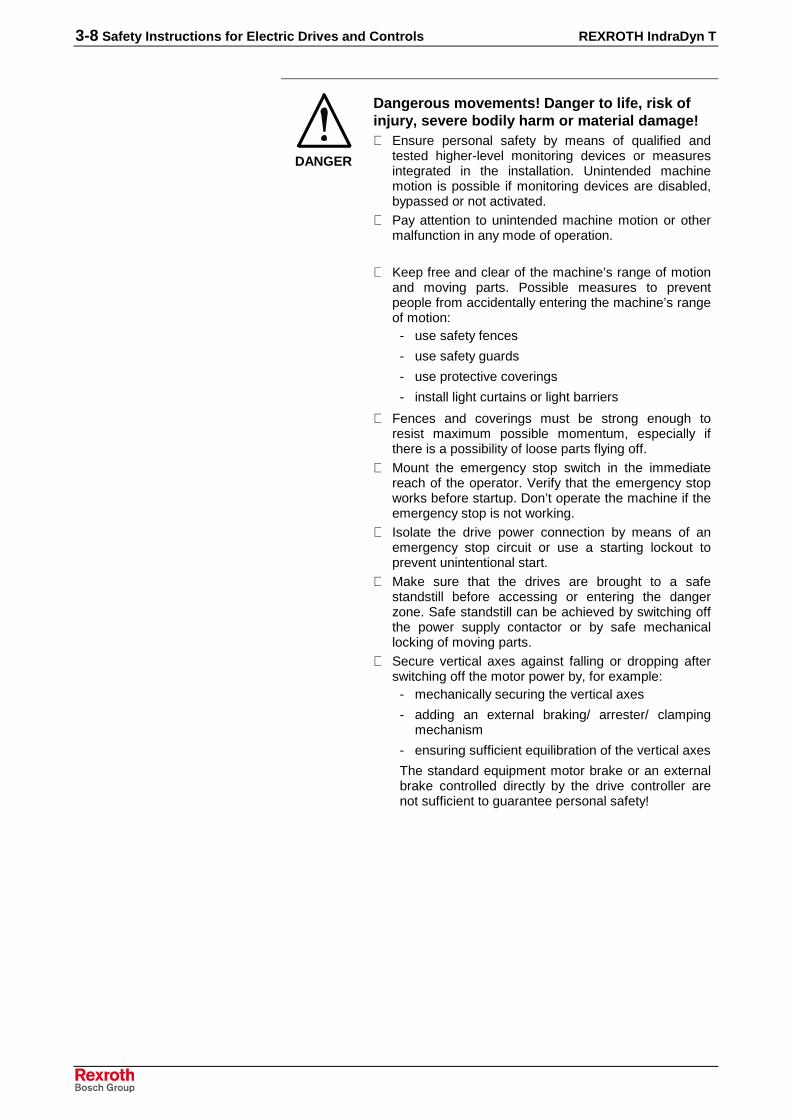
DANGER
Dangerous movements! Danger to life, risk ofinjury, severe bodily harm or material damage!⇒ Ensure personal safety by means of qualified and
tested higher-level monitoring devices or measuresintegrated in the installation. Unintended machinemotion is possible if monitoring devices are disabled,bypassed or not activated.
⇒ Pay attention to unintended machine motion or othermalfunction in any mode of operation.
⇒ Keep free and clear of the machine’s range of motionand moving parts. Possible measures to preventpeople from accidentally entering the machine’s rangeof motion:
- use safety fences
- use safety guards
- use protective coverings
- install light curtains or light barriers
⇒ Fences and coverings must be strong enough toresist maximum possible momentum, especially ifthere is a possibility of loose parts flying off.
⇒ Mount the emergency stop switch in the immediatereach of the operator. Verify that the emergency stopworks before startup. Don’t operate the machine if theemergency stop is not working.
⇒ Isolate the drive power connection by means of anemergency stop circuit or use a starting lockout toprevent unintentional start.
⇒ Make sure that the drives are brought to a safestandstill before accessing or entering the dangerzone. Safe standstill can be achieved by switching offthe power supply contactor or by safe mechanicallocking of moving parts.
⇒ Secure vertical axes against falling or dropping afterswitching off the motor power by, for example:
- mechanically securing the vertical axes
- adding an external braking/ arrester/ clampingmechanism
- ensuring sufficient equilibration of the vertical axes
The standard equipment motor brake or an externalbrake controlled directly by the drive controller arenot sufficient to guarantee personal safety!

REXROTH IndraDyn T Safety Instructions for Electric Drives and Controls 3-9
⇒ Disconnect electrical power to the equipment using amaster switch and secure the switch againstreconnection for:
- maintenance and repair work
- cleaning of equipment
- long periods of discontinued equipment use
⇒ Prevent the operation of high-frequency, remotecontrol and radio equipment near electronics circuitsand supply leads. If the use of such equipment cannotbe avoided, verify the system and the installation forpossible malfunctions in all possible positions ofnormal use before initial startup. If necessary, performa special electromagnetic compatibility (EMC) test onthe installation.
3.8 Protection Against Magnetic and Electromagnetic FieldsDuring Operation and Mounting
Magnetic and electromagnetic fields generated near current-carryingconductors and permanent magnets in motors represent a serious healthhazard to persons with heart pacemakers, metal implants and hearingaids.
WARNING
Health hazard for persons with heartpacemakers, metal implants and hearing aids inproximity to electrical equipment!⇒ Persons with heart pacemakers, hearing aids and
metal implants are not permitted to enter the followingareas:
- Areas in which electrical equipment and parts aremounted, being operated or started up.
- Areas in which parts of motors with permanentmagnets are being stored, operated, repaired ormounted.
⇒ If it is necessary for a person with a heart pacemakerto enter such an area, then a doctor must beconsulted prior to doing so. Heart pacemakers thatare already implanted or will be implanted in thefuture, have a considerable variation in their electricalnoise immunity. Therefore there are no rules withgeneral validity.
⇒ Persons with hearing aids, metal implants or metalpieces must consult a doctor before they enter theareas described above. Otherwise, health hazards willoccur.
3-10 Safety Instructions for Electric Drives and Controls REXROTH IndraDyn T
3.9 Protection Against Contact with Hot Parts
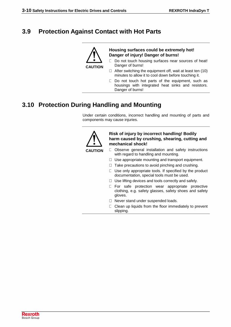
CAUTION
Housing surfaces could be extremely hot!Danger of injury! Danger of burns!⇒ Do not touch housing surfaces near sources of heat!
Danger of burns!⇒ After switching the equipment off, wait at least ten (10)
minutes to allow it to cool down before touching it.⇒ Do not touch hot parts of the equipment, such as
housings with integrated heat sinks and resistors.Danger of burns!
3.10 Protection During Handling and Mounting
Under certain conditions, incorrect handling and mounting of parts andcomponents may cause injuries.
CAUTION
Risk of injury by incorrect handling! Bodilyharm caused by crushing, shearing, cutting andmechanical shock!⇒ Observe general installation and safety instructions
with regard to handling and mounting.⇒ Use appropriate mounting and transport equipment.⇒ Take precautions to avoid pinching and crushing.⇒ Use only appropriate tools. If specified by the product
documentation, special tools must be used.⇒ Use lifting devices and tools correctly and safely.⇒ For safe protection wear appropriate protective
clothing, e.g. safety glasses, safety shoes and safetygloves.
⇒ Never stand under suspended loads.⇒ Clean up liquids from the floor immediately to prevent
slipping.

REXROTH IndraDyn T Safety Instructions for Electric Drives and Controls 3-11
3.11 Battery Safety
Batteries contain reactive chemicals in a solid housing. Inappropriatehandling may result in injuries or material damage.
CAUTION
Risk of injury by incorrect handling!⇒ Do not attempt to reactivate discharged batteries by
heating or other methods (danger of explosion andcauterization).
⇒ Never charge non-chargeable batteries (danger ofleakage and explosion).
⇒ Never throw batteries into a fire.⇒ Do not dismantle batteries.⇒ Do not damage electrical components installed in the
equipment.
Note: Be aware of environmental protection and disposal! Thebatteries contained in the product should be considered ashazardous material for land, air and sea transport in the senseof the legal requirements (danger of explosion). Disposebatteries separately from other waste. Observe the legalrequirements in the country of installation.
3.12 Protection Against Pressurized Systems
Certain motors and drive controllers, corresponding to the information inthe respective Project Planning Manual, must be provided withpressurized media, such as compressed air, hydraulic oil, cooling fluidand cooling lubricant supplied by external systems. Incorrect handling ofthe supply and connections of pressurized systems can lead to injuries oraccidents. In these cases, improper handling of external supply systems,supply lines or connections can cause injuries or material damage.
CAUTION
Danger of injury by incorrect handling ofpressurized systems !⇒ Do not attempt to disassemble, to open or to cut a
pressurized system (danger of explosion).⇒ Observe the operation instructions of the respective
manufacturer.⇒ Before disassembling pressurized systems, release
pressure and drain off the fluid or gas.⇒ Use suitable protective clothing (for example safety
glasses, safety shoes and safety gloves)⇒ Remove any fluid that has leaked out onto the floor
immediately.
Note: Environmental protection and disposal! The media used in theoperation of the pressurized system equipment may not beenvironmentally compatible. Media that are damaging theenvironment must be disposed separately from normal waste.Observe the legal requirements in the country of installation.

3-12 Safety Instructions for Electric Drives and Controls REXROTH IndraDyn T
Notes

REXROTH IndraDyn T Technical Data 4-1
4 Technical DataThis chapter contains technical data of all motor units of the seriesIndraDyn T with the appropriate definitions.
4.1 Definitions
Operating ModesBosch Rexroth motors are documented according to the test criteria andmeasuring methods of EN 60034-1. Stated technical data refer to theoperating mode S1 (continuous operation) and S6 (periodic operation),each with liquid cooling and coolant water.
�
∆�� ∆��
��
�
�
���
��
Θ
�
���
��
Θ
S6S1MBTDefinitions2.EPS
P: LoadPV: Electric lossesΘ: TemperatureΘmax: Highest temperature (stator)t: TimeTC: Cycle duration∆tP: Operating time with constant load∆tV: Idle time
Fig. 4-1: Operating modes according to EN 60034-1: 1998
ON timeThe operating mode S6 is supplemented by specification of the ON time(ED) in %. The ON time is calculated with the following formula:
%100T
tED
C
P ⋅⋅⋅⋅====∆
ED: Cyclic duration factor in %TC: Cycle duration∆tP: Operating time with constant load
Fig. 4-2: Cyclic duration factor

4-2 Technical Data REXROTH IndraDyn T
ParametersAvailable torque that can be output at the rated speed in operating modeS1. Unit Newtonmetre (Nm).
Typical useful speed defined by the manufacturer. Depending on theparticular application, other useful speeds are possible (see speed-torquecurve).
Power consumption of the motor at the rated speed and load with ratedtorque, specified in kilowatts (kW).
Phase current of the motor at the rated speed and load with rated torque,specified as root-mean-square value in ampere (A).
At peak current Imax available maximum torque in Nm. The achievablemaximum torque depends on the drive controller used.
Peak current (root-mean-square) of the motor at Mmax. Unit Ampère (A).
The moment of inertia of the rotor without bearing and encoder. Unit(kgm²).
Relation of torque increase to the motor phase-current (root-mean-square). Unit (Nm/A). Guilty up to the rated current IN.
Root-mean-square of the induced motor voltage in dependence with themotor speed. Unit (V/min–1).
Winding resistance measured between two phases in ohms (Ù).
The mass of stator and rotor, without bearing and encoder, stated inkilogram (kg).
Maximum allowed speed of the motor in (min-1). Normally restricted bymechanical factors like centrifugal force or bearing load.
Number of pole pairs of the motor.
Duration of the temperature rise to 63% of the final temperature of thestators under load with rated torque in S1-operation and liquid cooling.
0%
63%
100%
t [min]
Θmax
Tth 1
~ 5 x TthΘ
MBTDefinitions3.eps
(1): Course of the stator temperature over timeTth: Thermal time constant
Fig. 4-3: Thermal time constant
Rated torque MN
Rated speed nN
Rated output PN
Rated current
Maximum torque
Peak current
Moment of inertia of the rotor JM)
Torque constant at 20 °C KM
Voltage constant at 20°C Kemf
Winding resistance at 20 C R12
Stator/Rotor mass
Maximum speed nmax
Pol pair number
Thermal time constant Tth

REXROTH IndraDyn T Technical Data 4-3
Operating characteristicThe following sample characteristic curves explain the operating behaviorof IndraDyn T motors, as does information found in the motor data sheet.
��
�
n [min-1]
Mmax
MN
MmaxnN nmax
MBTDefinitions4.EPS
Mmax: Maximum speedMN Rated torquenN Rated speednmax Maximum speed
Fig. 4-4: Example motor characteristic curve
Note: The achievable torque depends on the drive controller used.The reference value for the characteristic curves of the motoris an DC-bus voltage of 540VDC.

4-4 Technical Data REXROTH IndraDyn T
4.2 Data sheet size 210
Description Symbol Size 210
Motor data 1)
Frame length A C C D E RWinding code 0027 0027 0050 0070 0027 0035
Rated torque MN Nm 50 120 120 150 240 105
Rated speed nN min-1270 270 500 700 270 350
Rated performance PN kW 1,4 3,4 6,9 11 6,8 3,8
Rated current IN A 7 13 25 32 24 13
Maximum torque 2) Mmax Nm 100 250 250 300 500 240
Maximum voltage Imax A 25 50 100 120 90 44
Maximum speed nmax min-1600 600 1200 1200 600 750
Minimum strand cross-section 3) A mm² 2,5 4 4 6 4 1,5
Moment of inertia of the rotor Jm kgm² 0,012 0,023 0,023 0,027 0,042 0,024
Constant torque at 20°C Km Nm/A 7,1 9,2 4,8 4,7 10 8,08
Constant voltage at 20°C 4) Kemf V/min–10,51 0,62 0,31 0,31 0,7 0,53
Winding resistance at 20°C R12 Ohm 11,1 4,88 1,23 1,4 2,16 5,25
Inductivity at mounted rotor LA mH 53,3 28,6 7,6 6,9 14,1 19,9
Mass stator m kg 7,2 11,5 11,5 13,8 18,8 8,8
Mass rotor m kg 3 4,8 4,8 5,8 7,8 4,4
Thermal time constant tth min i.p. i.p. i.p. i.p. i.p. i.p.
Permissible rotor temperature t °C 100
Permissible ambient temperature t °C 0...40
Permissible storage and transporttemperature t °C -20...+80
Insulation class according to DIN VDE0530-1 F
Degree of protection according toIEC60050-411 IP00
Number of pole pairs 20
Liquid CoolingRated power loss PVN kW 1,2 2,6 2,8 3,4 4 1,5
Liquid cooling temperature at inletTemperature rise at PVN
5)ϑ in∆ϑ N
°CK
10...4010
Necessary liquid cooling flow at ∆ϑ N5) QN l/min 6 6 6 6 6 6
Decompression at QN ∆p bar 0,1 0,1 0,1 0,1 0,1 0,4
Permissible inlet pressure pmax bar 3
Volume liquid cooling duct V l 0,064 0,175 0,175 0,21 0,366 0,1851) The determined values are root-mean-square according to IEC 60034-1, if no others are given.
Reference value540 VDC DC bus voltage.2) The achievable maximum torque depends on the drive controller used.3) Rated according to EN60204-1 (1993), installation mode B2 and conversion factor for Bosch Rexroth cables at
40°C ambient temperature. When using other cables, larger cross sections may be necessary.4) EMF = electromagnetic force. Root-mean-square applying to 1 min-1.5) The datas refer to operation with liquid cooling, cooling medium water.
Fig. 4-5: Data sheet size 210

REXROTH IndraDyn T Technical Data 4-5
Motor characteristic curve MBT210
Note: Because of the wide range of motor-drive combinations, thefollowing 2 motor-characteristic curves are shown exemplified.As a reference value, a DC-bus voltage of 540VDC waschosen. You receive the corresponding motor-characteristiccurves for your application from your Rexroth sales office.
0
50
100
150
200
250
300
0
50
100
150
200
250
300
350
400
450
500
550
600
650
Drehzahl/speed n in min-1
Drehmoment/Torque in Nm
M max
M N
nN nmax
Motorkennlinie_MBT210C_0027.eps
Fig. 4-6: Speed-torque characteristic curve MBT210C_0027
0
50
100
150
200
250
300
350
0
100
200
300
400
500
600
700
800
900
1000
1100
1200
1300
Drehzahl/speed n in min-1
Drehmoment/Torque in Nm
M max
M N
nN nmax
Motorkennlinie_MBT210D_0070.eps
Fig. 4-7: Speed-torque characteristic curve MBT210D_0070

4-6 Technical Data REXROTH IndraDyn T
4.1 Data sheet size 290
Description Symbol Size 290
Motor data 1)
Frame length B D D E E
Winding code 0018 0002 0018 0004 0018
Rated torque MN Nm 220 330 350 575 575
Rated speed nN min-1180 25 180 40 180
Rated performance PN kW 4,1 0,9 6,6 2,4 10,8
Rated current IN A 14,8 6,3 26 12,5 35
Maximum torque 2) Mmax Nm 460 700 700 1150 1150
Maximum voltage Imax A 60 25 100 50 125
Maximum speed nmax min-1350 90 350 130 350
Minimum strand cross-section 3) A mm² 4 4 4 4 6
Moment of inertia of the rotor Jm kgm² 0,08 0,11 0,11 0,17 0,17
Constant torque at 20°C Km Nm/A 14,9 52,4 13,5 46 16,4
Constant voltage at 20°C 4) Kemf V/min-11,16 4,67 0,96 3,62 1,04
Winding resistance at 20°C R12 Ohm 6,3 42,9 2,25 15,9 1,59
Inductivity at mounted rotor LA mH 35,3 270,2 13,4 102,2 9,1
Mass Stator m kg 13,5 20 20 25,1 25,1
Mass Rotor m kg 6,2 9 9 11,6 11,6
Thermal time constant tth min i.p. i.p. i.p. i.p. i.p.
Permissible rotor temperature t °C 100
Permissible ambient temperature t °C 0...40
Permissible storage and transporttemperature t °C -20...+80
Insulation class according to DIN VDE0530-1 F
Degree of protection according toIEC60050-411 IP00
Number of pole pairs 30
Liquid CoolingRated power loss PVN kW 3 4,7 4,2 5,2 5,5
Liquid cooling temperature at inletTemperature rise at PVN 5)
ϑ in
∆ϑ N
°CK
10...4010
Necessary liquid cooling flow at ∆ϑ N5) QN l/min 5 7 7 9 9
Decompression at QN ∆p bar 0,1 0,1 0,1 0,1 0,1
Permissible inlet pressure pmax bar 3
Volume liquid cooling duct V l 0,2 0,31 0,31 0,55 0,551) The determined values are root-mean-square according to IEC 60034-1, if no others are given.
Reference value540 VDC DC bus voltage.2) The achievable maximum torque depends on the drive controller used.3) Rated according to EN60204-1 (1993), installation mode B2 and conversion factor for Bosch Rexroth cables at
40°C ambient temperature. When using other cables, larger cross sections may be necessary.4) EMF = electromagnetic force. Root-mean-square applying to 1 min-1.5) The datas refer to operation with liquid cooling, cooling medium water.
Abb. 4-1: Data sheet size 290
REXROTH IndraDyn T Technical Data 4-7
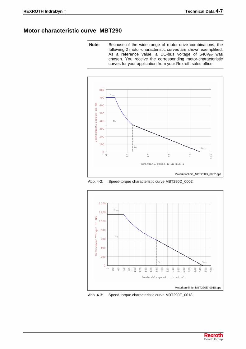
Motor characteristic curve MBT290
Note: Because of the wide range of motor-drive combinations, thefollowing 2 motor-characteristic curves are shown exemplified.As a reference value, a DC-bus voltage of 540VDC waschosen. You receive the corresponding motor-characteristiccurves for your application from your Rexroth sales office.
0
100
200
300
400
500
600
700
800
0
20
40
60
80
100
Drehzahl/speed n in min-1
Drehmoment/Torque in Nm
M max
M N
nN nmax
Motorkennlinie_MBT290D_0002.eps
Abb. 4-2: Speed-torque characteristic curve MBT290D_0002
0
200
400
600
800
1000
1200
1400
0
20
40
60
80
100
120
140
160
180
200
220
240
260
280
300
320
340
360
380
Drehzahl/speed n in min-1
Drehmoment/Torque in Nm
M max
M N
nN nmax
Motorkennlinie_MBT290E_0018.eps
Abb. 4-3: Speed-torque characteristic curve MBT290E_0018

4-8 Technical Data REXROTH IndraDyn T
4.2 Data sheet size 360
Description Symbol Size 360
Motor data 1)
Frame length B D E
Winding code 0018 0018 0018
Rated torque MN Nm 350 525 875
Rated speed nN min-1180 180 180
Rated performance PN kW 7,1 9,9 16,5
Rated current IN A 20 28 42
Maximum torque 2) Mmax Nm 900 1150 1900
Maximum voltage Imax A 70 100 141
Maximum speed nmax min-1330 300 300
Minimum strand cross-section 3) A mm² 4 4 10
Moment of inertia of the rotor Jm kgm² 0,19 0,27 0,44
Constant torque at 20°C Km Nm/A 18,8 18,8 20,8
Constant voltage at 20°C 4) Kemf V/min-11,93 1,72 1,89
Winding resistance at 20°C R12 Ohm 2,25 1,9 1,3
Inductivity at mounted rotor LA mH 18,2 15,5 9,9
Mass Stator m kg 23 28,8 40,3
Mass Rotor m kg 9,8 13,5 20,9
Thermal time constant tth min i.p. i.p. i.p.
Permissible rotor temperature t °C 100
Permissible ambient temperature t °C 0...40
Permissible storage and transporttemperature t °C -20...+80
Insulation class according to DIN VDE0530-1 F
Degree of protection according toIEC60050-411 IP00
Number of pole pairs 25
Liquid CoolingRated power loss PVN kW 2,7 i.p. i.p.
Liquid cooling temperature at inletTemperature rise at PVN 5) 5
ϑ in
∆ϑ N
°CK
10...4010
Necessary liquid cooling flow at ∆ϑ N5) 5 QN l/min 6 6 6
Decompression at QN ∆p bar 0,1 0,1 0,1
Permissible inlet pressure pmax bar 3
Volume liquid cooling duct V l 0,27 0,39 0,691) The determined values are root-mean-square according to IEC 60034-1, if no others are given.
Reference value540 VDC DC bus voltage.2) The achievable maximum torque depends on the drive controller used.3) Rated according to EN60204-1 (1993), installation mode B2 and conversion factor for Bosch Rexroth cables at
40°C ambient temperature. When using other cables, larger cross sections may be necessary.4) EMF = electromagnetic force. Root-mean-square applying to 1 min-1.5) The datas refer to operation with liquid cooling, cooling medium water.
Abb. 4-4: Data sheet size 360

REXROTH IndraDyn T Technical Data 4-9
Motor characteristic curve MBT360
Note: Because of the wide range of motor-drive combinations, thefollowing 2 motor-characteristic curves are shown exemplified.As a reference value, a DC-bus voltage of 540VDC waschosen. You receive the corresponding motor-characteristiccurves for your application from your Rexroth sales office.
0
200
400
600
800
1000
0
20
40
60
80
100
120
140
160
180
200
220
240
260
280
300
320
340
360
Drehzahl/speed n in min-1
Drehmoment/Torque in Nm
M max
M N
nN nmax
Motorkennlinie_MBT360B_0018.eps
Abb. 4-5: Speed-torque characteristic curve MBT360B_0018
0
200
400
600
800
1000
1200
1400
1600
1800
2000
0
20
40
60
80
100
120
140
160
180
200
220
240
260
280
300
320
Drehzahl/speed n in min-1
Drehmoment/Torque in Nm
M max
M N
nN nmax
Motorkennlinie_MBT360E_0018.eps
Abb. 4-6: Speed-torque characteristic curve MBT360E_0018

4-10 Technical Data REXROTH IndraDyn T
4.3 Data sheet size 450
Description Symbol Size 450
Motor data 1)
Frame length B D E
Winding code 0012 0012 0012
Rated torque MN Nm 540 810 1400
Rated speed nN min-1120 120 120
Rated performance PN kW 6,8 10,2 17,6
Rated current IN A 22 33 46
Maximum torque 2) Mmax Nm 1200 1800 3250
Maximum voltage Imax A 70 100 125
Maximum speed nmax min-1250 250 220
Minimum strand cross-section 3) A mm² 6 6 10
Moment of inertia of the rotor Jm kgm² 0,45 0,64 1,01
Constant torque at 20°C Km Nm/A 24,5 24,5 30,4
Constant voltage at 20°C 4) Kemf V/min-11,48 1,48 1,93
Winding resistance at 20°C R12 Ohm 2,3 1,35 1,1
Inductivity at mounted rotor LA mH 19 12,7 10
Mass Stator m kg 31 38,7 54,2
Mass Rotor m kg 13 17,9 27,7
Thermal time constant tth min i.p. i.p. i.p.
Permissible rotor temperature t °C 100
Permissible ambient temperature t °C 0...40
Permissible storage and transporttemperature t °C -20...+80
Insulation class according to DIN VDE0530-1 F
Degree of protection according toIEC60050-411 IP00
Number of pole pairs 30 30 30
Liquid CoolingRated power loss PVN kW i.p. i.p. 6,6
Liquid cooling temperature at inletTemperature rise at PVN 5) 5
ϑ in
∆ϑ N
°CK
10...4010
Necessary liquid cooling flow at ∆ϑ N5) 5 QN l/min 6 6 9,6
Decompression at QN ∆p bar 0,1 0,1 0,1
Permissible inlet pressure pmax bar 3 3 3
Volume liquid cooling duct V l 0,33 0,48 0,861) The determined values are root-mean-square according to IEC 60034-1, if no others are given.
Reference value540 VDC DC bus voltage.2) The achievable maximum torque depends on the drive controller used.3) Rated according to EN60204-1 (1993), installation mode B2 and conversion factor for Bosch Rexroth cables at
40°C ambient temperature. When using other cables, larger cross sections may be necessary.4) EMF = electromagnetic force. Root-mean-square applying to 1 min-1.5) The datas refer to operation with liquid cooling, cooling medium water.
Abb. 4-7: Data sheet size 450

REXROTH IndraDyn T Technical Data 4-11
Motor characteristic curve MBT450
Note: Because of the wide range of motor-drive combinations, thefollowing 2 motor-characteristic curves are shown exemplified.As a reference value, a DC-bus voltage of 540VDC waschosen. You receive the corresponding motor-characteristiccurves for your application from your Rexroth sales office.
0
200
400
600
800
1000
1200
1400
0
20
40
60
80
100
120
140
160
180
200
220
240
260
280
Drehzahl/speed n in min-1
Drehmoment/Torque in Nm
M max
M N
nN nmax
Motorkennlinie_MBT450B_0012.eps
Abb. 4-8: Speed-torque characteristic curve MBT450B_0012
0
500
1000
1500
2000
2500
3000
3500
0
20
40
60
80
100
120
140
160
180
200
220
240
Drehzahl/speed n in min-1
Drehmoment/Torque in Nm
M max
M N
nN nmax
Motorkennlinie_MBT450E_0012.eps
Abb. 4-9: Speed-torque characteristic curve MBT450E_0012

4-12 Technical Data REXROTH IndraDyn T
4.4 Data sheet size 530
Description Symbol Einheit Size 530
Motor data 1)
Frame length B C EWinding code 0010 0010 0010Rated torque MN Nm 800 1200 2100Rated speed nN min-1 100 100 100Rated performance PN kW 8,4 12,6 22Rated current IN A 28,6 31,2 64Maximum torque 2) Mmax Nm 1800 2700 4700Maximum voltage Imax A 71 88 212Maximum speed nmax min-1 200 150 200Minimum strand cross-section 3) A mm² 10 10 10Moment of inertia of the rotor Jm kgm² 0,92 1,25 1,92Constant torque at 20°C Km Nm/A 28 38,5 32,8Constant voltage at 20°C 4) Kemf V/min-1 1,89 2,81 2,09Winding resistance at 20°C R12 Ohm 1,39 1,9 0,52Inductivity at mounted rotor LA mH 16,2 23,2 7,5Mass Stator m kg 36 45 63Mass Rotor m kg 22 27,5 38,5Thermal time constant tth min i.p. i.p. i.p.Permissible rotor temperature t °C 100Permissible ambient temperature t °C 0...40Permissible storage and transport temperature t °C -20...+80Insulation class according to DIN VDE 0530-1 FDegree of protection according to IEC60050-411 IP00
Number of pole pairs 35 35 35
Liquid Cooling
Rated power loss PVN kW 3,7 5,5 6,5
Liquid cooling temperature at inletTemperature rise at PVN 5)
ϑ in
∆ϑ N
°CK
10...4010
Necessary liquid cooling flow at ∆ϑ N5) QN l/min 6 6 9,5
Decompression at QN ∆p bar 0,1 0,1 0,2Permissible inlet pressure pmax bar 3Volume liquid cooling duct V l 0,6 0,9 1,51) The determined values are root-mean-square according to IEC 60034-1, if no others are given.
Reference value540 VDC DC bus voltage.2) The achievable maximum torque depends on the drive controller used.3) Rated according to EN60204-1 (1993), installation mode B2 and conversion factor for Bosch Rexroth cables at
40°C ambient temperature. When using other cables, larger cross sections may be necessary.4) EMF = electromagnetic force. Root-mean-square applying to 1 min-1.5) The datas refer to operation with liquid cooling, cooling medium water.
Abb. 4-10: Data sheet size 530

REXROTH IndraDyn T Technical Data 4-13
Motor characteristic curve MBT530
Note: Because of the wide range of motor-drive combinations, thefollowing 2 motor-characteristic curves are shown exemplified.As a reference value, a DC-bus voltage of 540VDC waschosen. You receive the corresponding motor-characteristiccurves for your application from your Rexroth sales office.
0
200
400
600
800
1000
1200
1400
1600
1800
2000
0
20
40
60
80
100
120
140
160
180
200
220
Drehzahl/speed n in min-1
Drehmoment/Torque in Nm
M max
M N
nN nmax
Motorkennlinie_MBT530B_0010.eps
Abb. 4-11: Speed-torque characteristic curve MBT530B_0010
0
1000
2000
3000
4000
5000
0
20
40
60
80
100
120
140
160
180
200
220
Drehzahl/speed n in min-1
Drehmoment/Torque in Nm
M max
M N
nN nmax
Motorkennlinie_MBT530E_0010.eps
Abb. 4-12: Speed-torque characteristic curve MBT530E_0010

4-14 Technical Data REXROTH IndraDyn T
REXROTH IndraDyn T Dimension sheet IndraDyn T 5-1
5 Dimension sheet IndraDyn T
For your orientation:
The dimensions and installation drawings in this chapter are combinedaccording to the sizes. The drawings for each size always follow in thisorder:
• Standard dimension sheet of complete motors. One dimension sheetper variant “electrical connection”.
• Component drawing of the rotor.
• Installation drawing of a mounted rotor (example).
• Component drawing of the stator. One dimension sheet per variant“electrical connection”.
• Installation drawing of a mounted stator (example).
• Installation drawing of complete mounted rotor and stator (example)
The dimensions and tolerances shown in the drawings underlie thefollowing standards:
Longitudiual dimensions: DIN ISO 2768, part 1
Angular dimensions: DIN 7168 middle
Form and position tolerances: DIN ISO 1101
Note: The installation drawings are only examples for a way ofinstallation. It is not possible to show all installation variants ofthe different machines or use.
The binding installation drawings for a specific machine or useare made by the machine manufacturer himself.

5-2 Dimension sheet IndraDyn T REXROTH IndraDyn T
5.1 Dimension sheet size MBT210
Electrical connection “SN”
106-0393-4001-01.tif
Fig. 5-1: Dimension sheet MBT210 electrical connection “SN”

REXROTH IndraDyn T Dimension sheet IndraDyn T 5-3
Electrical connection “CN”
106-0393-4002-01.tif
Fig. 5-2: Dimension sheet MBT210 electrical connection “CN”

5-4 Dimension sheet IndraDyn T REXROTH IndraDyn T
Electrical connection “RN” (dimension sheet in preparation)
xxx.tif
Fig. 5-3: Dimension sheet MBT210 electrical connection “RN”

REXROTH IndraDyn T Dimension sheet IndraDyn T 5-5
Rotor MRT210
106-0393-4010-01.tif
Fig. 5-4: Dimension sheet rotor MRT210

5-6 Dimension sheet IndraDyn T REXROTH IndraDyn T
Rotor MRT210 mounted
106-0393-4011-01.tif
Fig. 5-5: Dimension sheet rotor MRT210 mounted

REXROTH IndraDyn T Dimension sheet IndraDyn T 5-7
Stator MST210 electrical connection “SN”
106-0393-4020-01.tif
Fig. 5-6: Dimension sheet stator MST210 electrical connection “SN”

5-8 Dimension sheet IndraDyn T REXROTH IndraDyn T
Stator MST210 electrical connection “CN”
106-0393-4021-01.tif
Fig. 5-7: Dimension sheet stator MST210 electrical connection “CN”

REXROTH IndraDyn T Dimension sheet IndraDyn T 5-9
Stator MST210 electrical connection “RN”
mst210rn.tif
Fig. 5-8: Dimension sheet stator MST210 electrical connection “RN”

5-10 Dimension sheet IndraDyn T REXROTH IndraDyn T
Stator MST210 mounted
106-0393-4022-01.tif
Fig. 5-9: Dimension sheet stator MST210 mounted

REXROTH IndraDyn T Dimension sheet IndraDyn T 5-11
Rotor and Stator MBT210 mounted
106-0393-4030-01.tif
Fig. 5-10: Dimension sheet MBT210, rotor and stator mounted

5-12 Dimension sheet IndraDyn T REXROTH IndraDyn T
5.2 Dimension sheet size MBT290
Electrical connection "SN"
106-0394-4001-01.tif
Fig. 5-1: Dimension sheet MBT290 electrical connection "SN"
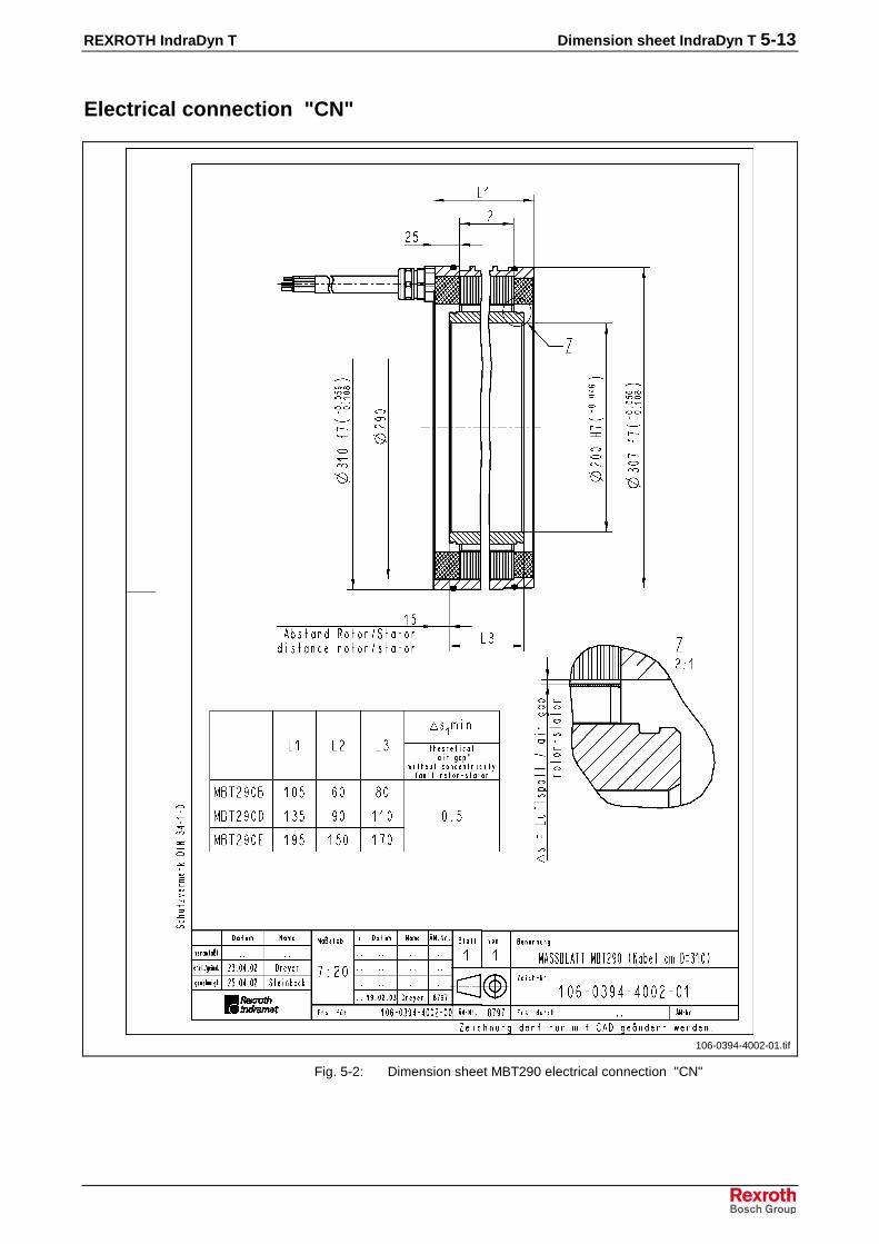
REXROTH IndraDyn T Dimension sheet IndraDyn T 5-13
Electrical connection "CN"
106-0394-4002-01.tif
Fig. 5-2: Dimension sheet MBT290 electrical connection "CN"

5-14 Dimension sheet IndraDyn T REXROTH IndraDyn T
Electrical connection "RN" (Dimension sheet in preparation)
xxx.tif
Fig. 5-3: Dimension sheet MBT290 electrical connection "RN"

REXROTH IndraDyn T Dimension sheet IndraDyn T 5-15
Rotor MRT290
106-0394-4010-00.tif
Fig. 5-4: Dimension sheet rotor MRT290

5-16 Dimension sheet IndraDyn T REXROTH IndraDyn T
Rotor MRT290 mounted
106-0394-4011-00.tif
Fig. 5-5: Dimension sheet rotor MRT290 mounted

REXROTH IndraDyn T Dimension sheet IndraDyn T 5-17
Stator MST290 electrical connection "SN"
106-0394-4020-01.tif
Fig. 5-6: Dimension sheet stator MST290 electrical connection "SN"

5-18 Dimension sheet IndraDyn T REXROTH IndraDyn T
Stator MST290 electrical connection "CN"
106-0394-4021-01.tif
Fig. 5-7: Dimension sheet stator MST290 electrical connection "CN"

REXROTH IndraDyn T Dimension sheet IndraDyn T 5-19
Stator MST290 electrical connection "RN"
mst290rn.tif
Fig. 5-8: Dimension sheet stator MST290 electrical connection "RN"

5-20 Dimension sheet IndraDyn T REXROTH IndraDyn T
Stator MST290 mounted
106-0394-4022-01.tif
Fig. 5-9: Dimension sheet stator MST290 mounted

REXROTH IndraDyn T Dimension sheet IndraDyn T 5-21
Rotor and Stator MBT290 mounted
106-0394-4030-01.tif
Fig. 5-10: Dimension sheet rotor and stator MBT290 mounted

5-22 Dimension sheet IndraDyn T REXROTH IndraDyn T
5.3 Dimension sheet size MBT360
Electrical connection "SN"
106-0382-4001-00.tif
Fig. 5-11: Dimension sheet MBT360 electrical connection "SN"

REXROTH IndraDyn T Dimension sheet IndraDyn T 5-23
Electrical connection "CN"
106-0382-4002-00.tif
Fig. 5-12: Dimension sheet MBT360 electrical connection "CN"

5-24 Dimension sheet IndraDyn T REXROTH IndraDyn T
Electrical connection "RN" (Dimension sheet in preparation)
xxx.tif
Fig. 5-13: Dimension sheet MBT360 electrical connection "RN"

REXROTH IndraDyn T Dimension sheet IndraDyn T 5-25
Rotor MRT360
106-0382-4010-00.tif
Fig. 5-14: Dimension sheet rotor MRT360

5-26 Dimension sheet IndraDyn T REXROTH IndraDyn T
Rotor MRT360 mounted
106-0382-4011-00.tif
Fig. 5-15: Dimension sheet rotor MRT360 mounted

REXROTH IndraDyn T Dimension sheet IndraDyn T 5-27
Stator MST360 electrical connection "SN"
106-0382-4020-00.tif
Fig. 5-16: Dimension sheet stator MST360 electrical connection "SN"

5-28 Dimension sheet IndraDyn T REXROTH IndraDyn T
Stator MST360 electrical connection "CN"
106-0382-4021-00.tif
Fig. 5-17: Dimension sheet stator MST360 electrical connection "CN"
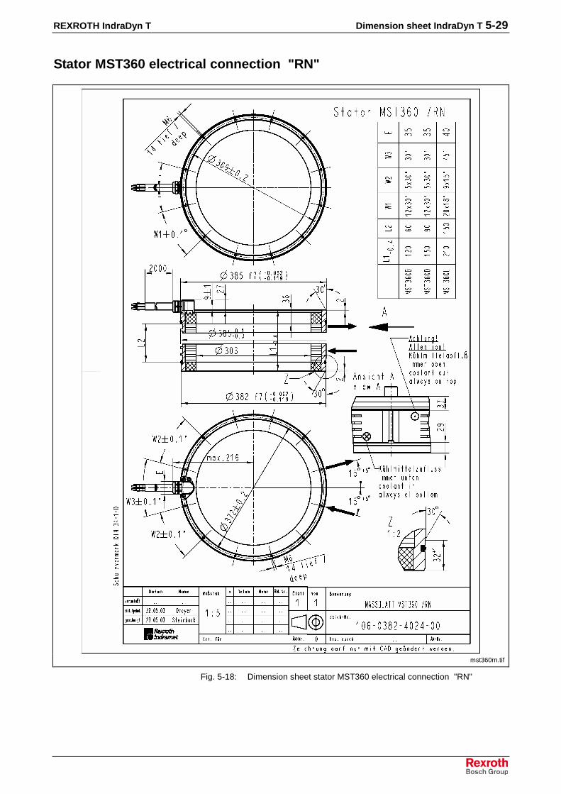
REXROTH IndraDyn T Dimension sheet IndraDyn T 5-29
Stator MST360 electrical connection "RN"
mst360rn.tif
Fig. 5-18: Dimension sheet stator MST360 electrical connection "RN"

5-30 Dimension sheet IndraDyn T REXROTH IndraDyn T
Stator MST360 mounted, electrical connection "SN"
106-0382-4022-00.tif
Fig. 5-19: Dimension sheet stator MST360 mounted, electrical connection"SN"

REXROTH IndraDyn T Dimension sheet IndraDyn T 5-31
Stator MST360 mounted, electrical connection "CN"
106-0382-4023-00.tif
Fig. 5-20: Dimension sheet Stator MST360 mounted, electrical connection"CN"
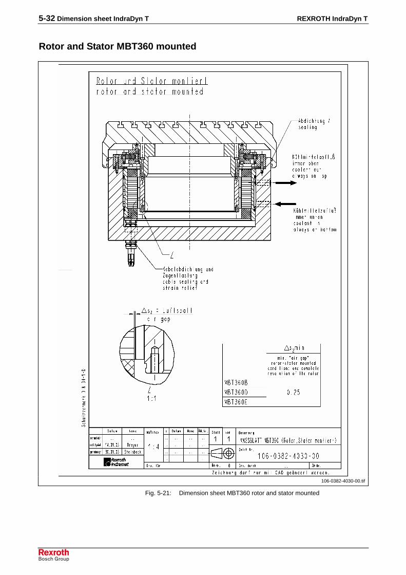
5-32 Dimension sheet IndraDyn T REXROTH IndraDyn T
Rotor and Stator MBT360 mounted
106-0382-4030-00.tif
Fig. 5-21: Dimension sheet MBT360 rotor and stator mounted

REXROTH IndraDyn T Dimension sheet IndraDyn T 5-33
5.4 Dimension sheet size MBT450
Electrical connection "SN"
106-0435-4001-02.tif
Fig. 5-22: Dimension sheet MBT450 electrical connection "SN"
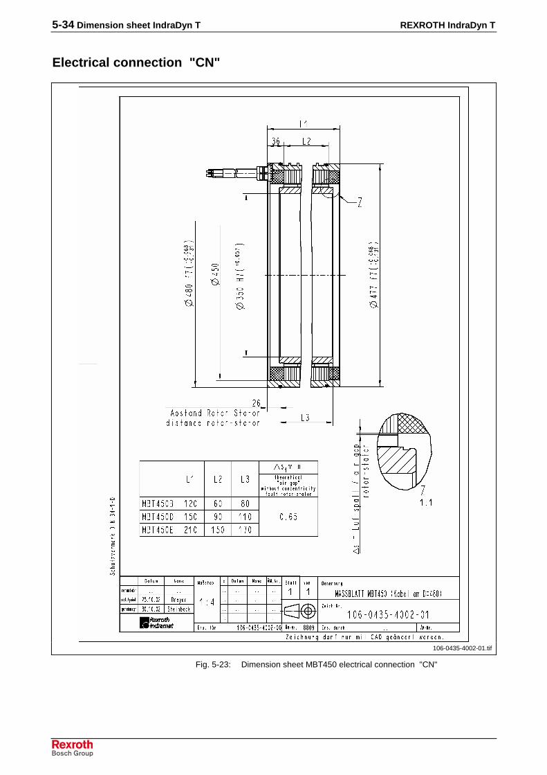
5-34 Dimension sheet IndraDyn T REXROTH IndraDyn T
Electrical connection "CN"
106-0435-4002-01.tif
Fig. 5-23: Dimension sheet MBT450 electrical connection "CN"

REXROTH IndraDyn T Dimension sheet IndraDyn T 5-35
Electrical connection "RN" (Dimension sheet in preparation)
xxx.tif
Fig. 5-24: Dimension sheet MBT450 electrical connection "RN"

5-36 Dimension sheet IndraDyn T REXROTH IndraDyn T
Rotor MRT450
106-0435-4010-00.tif
Fig. 5-25: Dimension sheet rotor MRT450

REXROTH IndraDyn T Dimension sheet IndraDyn T 5-37
Rotor MRT450 mounted
106-0435-4011-00.tif
Fig. 5-26: Dimension sheet rotor MRT450 mounted
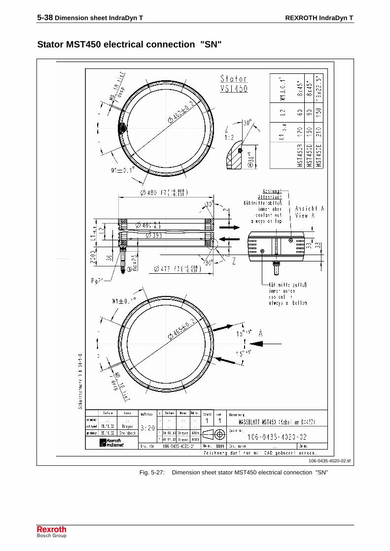
5-38 Dimension sheet IndraDyn T REXROTH IndraDyn T
Stator MST450 electrical connection "SN"
106-0435-4020-02.tif
Fig. 5-27: Dimension sheet stator MST450 electrical connection "SN"
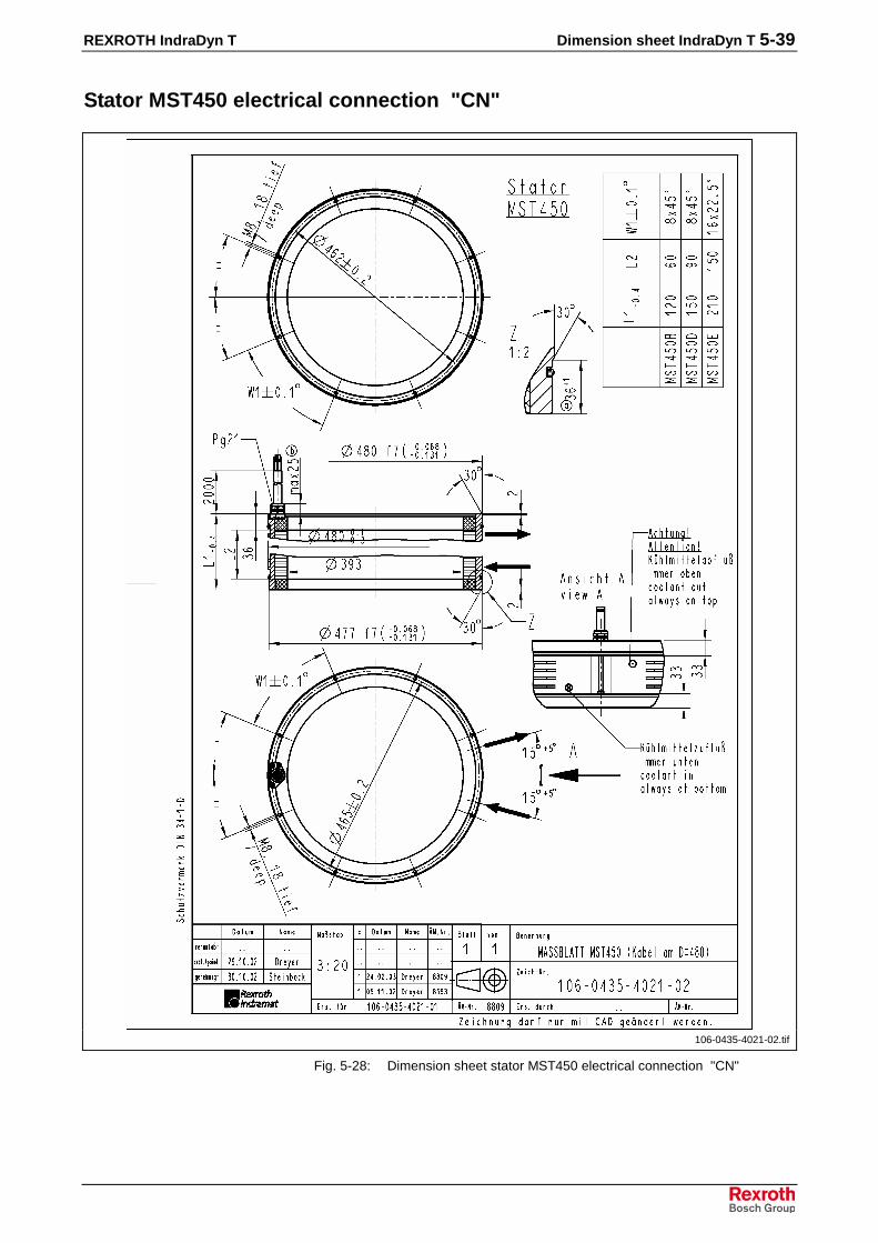
REXROTH IndraDyn T Dimension sheet IndraDyn T 5-39
Stator MST450 electrical connection "CN"
106-0435-4021-02.tif
Fig. 5-28: Dimension sheet stator MST450 electrical connection "CN"

5-40 Dimension sheet IndraDyn T REXROTH IndraDyn T
Stator MST450 electrical connection "RN"
mst450rn.tif
Fig. 5-29: Dimension sheet stator MST450 electrical connection "RN"

REXROTH IndraDyn T Dimension sheet IndraDyn T 5-41
Stator MST450 mounted
106-0435-4022-01.tif
Fig. 5-30: Dimension sheet stator MST450 mounted

5-42 Dimension sheet IndraDyn T REXROTH IndraDyn T
Rotor and Stator MBT450 mounted
106-0435-4030-01.tif
Fig. 5-31: Dimension sheet MBT450, rotor and stator mounted

REXROTH IndraDyn T Dimension sheet IndraDyn T 5-43
5.5 Dimension sheet size MBT530
Electrical connection "SN"
106-0374-4001-01.tif
Fig. 5-32: Dimension sheet MBT530 electrical connection "SN"

5-44 Dimension sheet IndraDyn T REXROTH IndraDyn T
Electrical connection "CN"
106-0374-4002-01.tif
Fig. 5-33: Dimension sheet MBT530 electrical connection "CN"

REXROTH IndraDyn T Dimension sheet IndraDyn T 5-45
Electrical connection "RN" (Dimension sheet in preparation)
xxx.tif
Fig. 5-34: Dimension sheet MBT530 electrical connection "RN"

5-46 Dimension sheet IndraDyn T REXROTH IndraDyn T
Rotor MRT530
106-0374-4010-00.tif
Fig. 5-35: Dimension sheet rotor MRT530
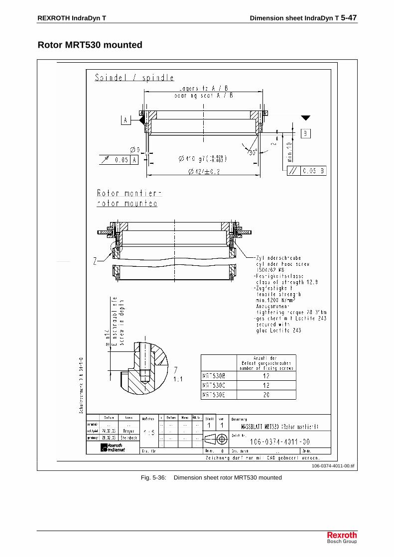
REXROTH IndraDyn T Dimension sheet IndraDyn T 5-47
Rotor MRT530 mounted
106-0374-4011-00.tif
Fig. 5-36: Dimension sheet rotor MRT530 mounted

5-48 Dimension sheet IndraDyn T REXROTH IndraDyn T
Stator MST530 electrical connection "SN"
106-0374-3020-01.tif
Fig. 5-37: Dimension sheet stator MST530 electrical connection "SN"

REXROTH IndraDyn T Dimension sheet IndraDyn T 5-49
Stator MST530 electrical connection "CN"
106-0374-3021-01.tif
Fig. 5-38: Dimension sheet stator MST530 electrical connection "CN"
5-50 Dimension sheet IndraDyn T REXROTH IndraDyn T
Stator MST530 electrical connection "RN"
xxx.tif
Fig. 5-39: Dimension sheet stator MST530 electrical connection "RN"
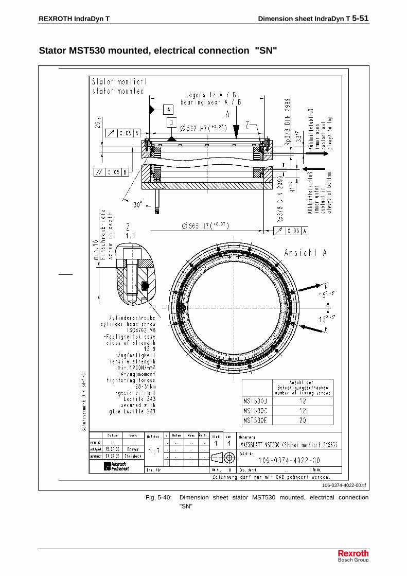
REXROTH IndraDyn T Dimension sheet IndraDyn T 5-51
Stator MST530 mounted, electrical connection "SN"
106-0374-4022-00.tif
Fig. 5-40: Dimension sheet stator MST530 mounted, electrical connection"SN"

5-52 Dimension sheet IndraDyn T REXROTH IndraDyn T
Stator MST530 mounted, electrical connection "CN"
106-0374-4023-00.tif
Fig. 5-41: Dimension sheet stator MST530 mounted, electrical connection"CN"
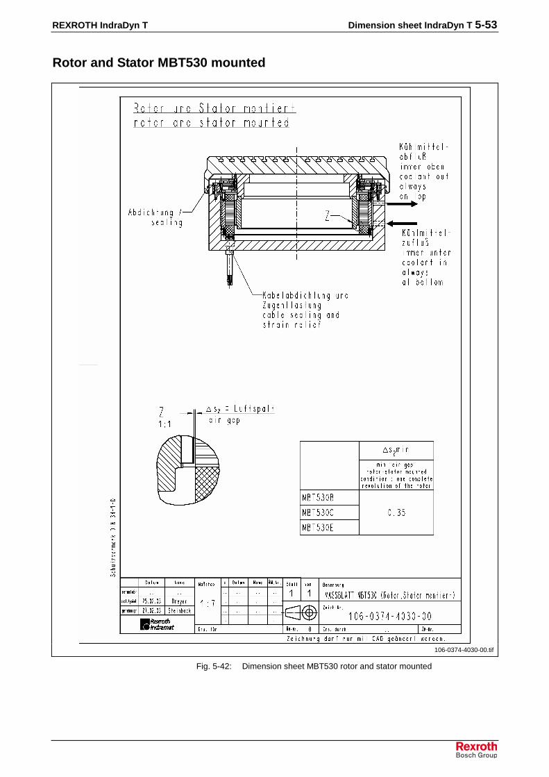
REXROTH IndraDyn T Dimension sheet IndraDyn T 5-53
Rotor and Stator MBT530 mounted
106-0374-4030-00.tif
Fig. 5-42: Dimension sheet MBT530 rotor and stator mounted

5-54 Dimension sheet IndraDyn T REXROTH IndraDyn T

REXROTH IndraDyn T Type Code 6-1
6 Type Code
The type code describes the motor variants that are supplied; it is thebasis for selecting and ordering products from Bosch Rexroth. Thisapplies to both new products as well as spare parts and repairs.
The torque motors IndraDyn T of Rexroth consist of the units “stator” and“rotor”. The type code is devided in “type code stator MST...” and “typecode rotor MRT...”.
The following description gives an overview over the separate columns ofthe type code (“short-text column”) and its meaning. You can find the typecode to a particular unit in the following chapter.
Type code rotor MRT
1. Product GroupMRT is the designation of an IndraDyn T rotor unit.
2. Motor Frame SizeThe motor frame size is derived from the stator dimensions andrepresents different power ranges.
3. Motor Frame LengthWithin a series, the graduation of increasing motor frame length isindicated by ID letters in alphabetic order.
Frame lengths are, for example, A, B, C, D and E.
4. Shape/mechanical construction3N marks the fastening of the rotor by screws.
5. Rotor - internal diameterMarks the internal diameter of the rotor in millimeter (mm).
6. Other typesReserved for optional types. You find a short description in theappropriate type code, mechanical details in the respective dimensionsheet.
Type code stator MST
1. ProductMST is the designation of an IndraDyn T stator unit.
Type code columns 1 2 3
Type code columns 4 5 6
Type code column 7
Type code columns 9 10
Type code columns 12 13 14 15
Type code columns 17 18 19 20
Type code columns 1 2 3

6-2 Type Code REXROTH IndraDyn T
2. Motor Frame SizeThe motor frame size is derived from the stator dimensions andrepresents different power ranges.
Available sizes: 210/290/360/450/530.
3. Motor Frame LengthWithin a series, the graduation of increasing motor frame length isindicated by ID letters in alphabetic order. The higher the motor framelength, the higher the torque.
Frame lengths are, for example, A, B, C, D and E.
4. Winding CodeThe winding codes “0010”, “0027”, etc. determine the winding variantsand indicate the rated speed.
Example: The rated speed for the winding “0027” is nN = 270 min-1. TheDC-bus voltage of 540 VDC is a fixed reference value.
A drive combination is selected acc. to the corresponding selection dataand operating characteristics.
5. Type of CoolingGenerally the motors of type IndraDyn T are fitted with a stator-coolingjacket for operating with liquid cooling.
Operating without liquid cooling is only permitted under certainrequirements. Therefore, reduced power data are considered in general.For information of the manufacturers see chapter “Application note”.
6. EncapsulationThe thermal encapsulation provides the thermal decoupling of motor andthe machine.
7. Motor encoderIndraDyn T-motors are delivered without a motor encoder. For informationabout the motor encoders see chapter 9 “Application notes”.
8. Electrical connectionThe electrical connection is made by a cable with 2m length (type “...301”on MST210 only 1.5m). All wires are provided with ferrules.
Depending on the installation within the machine, the cables could beconducted axially out of the stator’s bigger or smaller side or radially outof the bigger diameter. For more information see chapter 8 “Connectionsystem”.
9. Other typesReserved for optional types. You find a short description in theappropriate type code, mechanical details in the respective dimensionsheet.
Type code columns 4 5 6
Type code column 7
Type code columns 12 13 14 15
Type code column 14
Type code column 15
Type code columns 17 18
Type code columns 19 20
Type code columns 22 23 24 25

REXROTH IndraDyn T Type Code 6-3
6.1 Rotor MRT210
� � � � � � � �� � � � � � � � �
� � � � � � � � �
� � � � � � � � �
�
�� �����
�����������
� � � � � � � � � � � � � � � � �
� ��������� ��� ����������������� �����
�� ������������� �� ��������������������������������� ����
�� �������������� ����� ! ��������������������� ���"�#"�$"��"��
��� ���������������������������������� %&�&�����'�!('�)!��������������������������������� ����
�� ����������������!�������� ����� ��������������������������������������������������������� ������ ����� ��������������������������������������������������������� ����
"� #�������������� )&� � ((�!!*'+�� '*,� � *��! ������������������������������������������� ������� �*�� ��������������������������������������������������������������������������������� ������
$���%-�!&.��.& ����'�*%�'*�*'�/��/�&!�*��+� 0 &� 1���)&� ��*�*'������ �/�/2� �'�.�!&���/��/�&!�*��+� 0 &� 1���)&� ��*�*'������ �/�/2� �'�.�!&���/����/�&!�*��+� 0 &� 1���)&� ��*�*'������ �/�/"�/#/"�/$/� �.�/�/
�
�
�
�
INN-41-25-T21-01-M03-MRT2.EPS
Fig. 6-1: Type code MRT210

6-4 Type Code REXROTH IndraDyn T
6.2 Stator MST210
�� ��������� ���������� ���
� ����� ������ ��� �������������� ����
�� ������������� ������� ������� ����������
�� ������� ����� �� ������ ������������� ����! �� ������ ������������� ����!���"� �� ������ ������������� ���!� � ������ ������������� ����! �" ������ ������������� ���������"
�� ������������"�� �#$%#&'(()#�� ������������������������ �*
�� ����� ������+�� ,#��'(()#��-�'.��/���0�(1��'�2�%)��#(�3���� ��
�� ������������!�� ,#��(%��(�(0��'(&�0����������������������� ���
� �������������������4�� '�5)�'(�&%'��&��0(%������(0��&,#��
5#���0����0#(0&#�����0 ������������������������ ���4�� '�5)�0�&#�)'(�&%'��&��0(%������(0��&,#��
5#���0����0#(0&#�����0 ������������������������ ���4�� '�5)�'(�&%'��&��0(%������(0��&,#��
���))�0����0#(0&#�����0������������������������ ���
!� "������ ���6�� ,#��(%�'�5)��)��&�'(�&%'��&,#0� �������������������� �����6�� 2(,�01��&���0�(����(0'�5)���&�#���2�0���'�5)�
�)��&� ������������������������������������������� �����6�� �(�� ��������������������������������������������� �����6� �����0�(1�,#�'�#�����&(7�0#2)��2(�#��(0/���3��&
&��#��8����8 ������������������������������������� �����
#��$(�(0)�����8�8#�(�)9�:�#)�5)�,#���)�'�0#'�)'(���'�#(�8��8;���0&��#��8����8#�(�)9�:�#)�5)�,#���(�(0)�����8�8;���0&��#���8����8��&8����8�0�(�)9�:�#)�5)�,#���(�(0)�����8�8
� � � + ! 4 6��" � � � + ! 4 6
��" � � � + ! 4 6
��" � � � + ! 4 6
�"
����2)�<
%&&��'�������
� � � � � � 1 � � � ! 1 * � 1 � � � � 1 � � � �
�
�
�
�
�
RNC-41252-1022.EPS
Fig. 6-2: Type code MST210

REXROTH IndraDyn T Type Code 6-5
6.3 Rotor MRT290
� � � � � � � �� � � � � � � � �
� � � � � � � � �
� � � � � � � � �
�
�� �����
�����������
� � � � � � � � � � � � � � � �
� ��������� ��� ����������������� �����
�� ������������� �� ��������������������������������� ����
�� �������������� ����� !������������������������������� ��3"�$"��
��� ���������������������������������� %&�&�����'�!('�)! ������������������������������� ����
�� ����������������!�������� ���� ��������������������������������������������������������� ���
"� #�������������� �*�� ��������������������������������������������������������������������������������� ������
INN-41-25-T29-01-M02-MRT2.EPS
Fig. 6-3: Type code MRT290
6.4 Stator MST290
� � � � � � � �� � � � � � � � �
� � � � � � � � �
� � � � � � � � �
�
�� �����
�����������
� 4 � � � � � � � � 5 � � � 4 � � � � � �
� ��������� �4�������������������� ���4�
�� ������������� �� ��������������������������������� ����
�� �������������� ����� ! ����������������������������� ��3"�$"��
�� &��������������� �4���3 ��������������������������������� ������� �4���$ ��������������������������������� ���"������ �4���� ��������������������������������� ���"���
�� '�������������� �&6,&.�(**�&�� ��������������������������������������������������������� ��5
"� (���)��������� )&� � �,�&�&,��(**�&���7 (8���9� �'�*���( �!,� �&*�: ���
*� ���������������� )&� *,���*�*'���(*.�' ����������������������������������������������������� ���
+� (��������������������� ( 1���(*�.,(��.�� '*,� �!� �*'���.�)&�
1&���'�����'&*'�.& ����'� ����������������������������������������������������������� ��#���� ( 1���' .& ��(*�.,(��.�� '*,� �!� �*'���.�)&�
1&���'�����'&*'�.& ����' ����������������������������������������������������������� ������� ( 1���(*�.,(��.�� '*,� �!� �*'���.�)&�
!� ���'�����'&*'�.& ����'������������������������������������������������������������ ��4�
,� #�������������� �*�� ��������������������������������������������������������������������������������������������������� ������
INN-41-25-T29-02-M04-MST2.EPS
Fig. 6-4: Type code MST290

6-6 Type Code REXROTH IndraDyn T
6.5 Rotor MRT360
� � � � � � � �� � � � � � � � �
� � � � � � � � �
� � � � � � � � �
�
�� �����
�����������
� � � � � 3 � � � � � � � � � � �
� ��������� ��� ����������������� �����
�� ������������� �� ������������������������������� ����
�� �������������� ����� !������������������������������� ��3"�$"��
��� ���������������������������������� %&�&�����'�!('�)! ������������������������������� ����
�� ����������������!�������� ����� ��������������������������������������������������������� ����
"� #�������������� �*�� ��������������������������������������������������������������������������������� ������
INN-41-25-T36-01-M02-MRT2.EPS
Fig. 6-5: Type code MRT360
6.6 Stator MST360
� � � � � � � �� � � � � � � � �
� � � � � � � � �
� � � � � � � � �
�
�� �����
�����������
� 4 � � � � � � � � 5 � � � 4 � � � � � �
� ��������� �4�������������������� ���4�
�� ������������� �� ��������������������������������� ����
�� �������������� ����� ! ����������������������������� ��3"�$"��
�� &��������������� �4���3 ������������������������������������������� ������� �4���$ ������������������������������������������� ������� �4���� ������������������������������������������� ����
�� ������������� �&6,&.�(**�&�� ��������������������������������������������������������� ��5
"� (���)��������� )&� �(**�&���7 (8���9� �'�*���( �!,� �&*�: ����������������� ���
*� ���������������� )&� *,���*�*'���(*.�' ����������������������������������������������������� ���
+� (��������������������� ( 1���(*�.,(��.�� '*,� �!� �*'���.�)&�
1&���'�����'&*'�.& ����'������������������������������������������������������������ ��#���� ( 1���' .& ��(*�.,(��.�� '*,� �!� �*'���.�)&�
1&���'�����'&*'�.& ����' ����������������������������������������������������������� ������� ( 1���(*�.,(��.�� '*,� �!� �*'���.�)&�
!� ���'�����'&*'�.& ����'� ��������������������������������������������������������� ��4�
,� #�������������� �*�� ��������������������������������������������������������������������������������������������������� ������
INN-41-25-T36-02-M04-MST2.EPS
Fig. 6-6: Type code MST360

REXROTH IndraDyn T Type Code 6-7
6.7 Rotor MRT450
� � � � � � � �� � � � � � � � �
� � � � � � � � �
� � � � � � � � �
�
�� �����
�����������
� � � � 3 � � � � � � � � � �
� ��������� ��� ����������������� �����
�� ������������� � ��������������������������������� ���
�� �������������� ����� !������������������������������� ��3"�$"��
��� ���������������������������������� %&�&�����'�!('�)! ������������������������������� ����
�� ����������������!�������� ���� ��������������������������������������������������������� ���
"� #�������������� �*�� ��������������������������������������������������������������������������������� ������
INN-41-25-T45-01-M02-MRT2.EPS
Fig. 6-7: Type code MRT450
6.8 Stator MST450
� � � � � � � �� � � � � � � � �
� � � � � � � � �
� � � � � � � � �
�
�� �����
�����������
� 4 � � � � � � � 5 � � � # � � � � � �
� ��������� �4�������������������� ���4�
�� ������������� � ��������������������������������� ���
�� �������������� ����� !������������������������������� ��3"�$"��
�� &��������������� �4��3 ������������������������������������������� ������� �4��$ ������������������������������������������� ������� �4��� ������������������������������������������� ����
�� ������������� �&6,&.�(**�&�� ��������������������������������������������������������� ��5
"� (���)��������� )&� �(**�&���7 (8���9� �'�*���( �!,� �&*�: ����������������� ���
*� ���������������� )&� *,���*�*'���(*.�' ����������������������������������������������������� ���
+� (��������������������� ( 1���(*�.,(��.�� '*,� �!� �*'���.�)&�
1&���'�����'&*'�.& ����'������������������������������������������������������������ ��#���� ( 1���' .& ��(*�.,(��.�� '*,� �!� �*'���.�)&�
1&���'�����'&*'�.& ����' ����������������������������������������������������������� ������� ( 1���(*�.,(��.�� '*,� �!� �*'���.�)&�
!� ���'�����'&*'�.& ����'� ��������������������������������������������������������� ��4�
,� #�������������� �*�� ��������������������������������������������������������������������������������������������������� ������
INN-41-25-T45-02-M03-MST2.EPS
Fig. 6-8: Type code MST450

6-8 Type Code REXROTH IndraDyn T
6.9 Rotor MRT530
� � � � � � � �� � � � � � � � �
� � � � � � � � �
� � � � � � � � �
�
�� �����
�����������
� � � � 3 � � � � � � � � � � �
� ��������� ��� ����������������� �����
�� ������������� � ��������������������������������� ���
�� �������������� ����� ! ������������������������� ��3"�#"�$"��
��� ���������������������������������� %&�&�����'�!('�)! ������������������������������� ����
�� ����������������!�������� ����� ��������������������������������������������������������� ����
"� #�������������� �*�� ��������������������������������������������������������������������������������� ������
INN-41-25-T53-01-M04-MRT2.EPS
Fig. 6-9: Type code MRT530
6.10 Stator MST530
� � � � � � � �� � � � � � � � �
� � � � � � � � �
� � � � � � � � �
�
�� �����
�����������
� 4 � � 3 � � � 5 � � � # � � � � � �
� ��������� �4�������������������� ���4�
�� ������������� � ��������������������������������� ���
�� �������������� ����� !������������������������������� ��3"�#"��
�� &��������������� �4��3 ������������������������������������������� ������ �4��# ������������������������������������������� ������ �4��� ������������������������������������������� ���
�� ������������� �&6,&.�(**�&�� ��������������������������������������������������������� ��5�� !,&� 1���%*'�!,'% (��(**�&�� ����������������������������������� ��4
"� (���)��������� )&� �(**�&���7 (8���9� �'�*���( �!,� �&*�:������������������� ���
*� ���������������� )&� *,���*�*'���(*.�' ����������������������������������������������������� ���
+� (��������������������� ( 1���(*�.,(��.�� '*,� �!� �*'���.�)&�
1&���'�����'&*'�.& ����'������������������������������������������������������������ ��#���� ( 1���' .& ��(*�.,(��.�� '*,� �!� �*'���.�)&�
1&���'�����'&*'�.& ����' ����������������������������������������������������������� ������� ( 1���(*�.,(��.�� '*,� �!� �*'���.�)&�
!� ���'�����'&*'�.& ����'� ��������������������������������������������������������� ��4�
,� #�������������� �*�� ��������������������������������������������������������������������������������������������������� ������
$���%#**�&����*.��/4/�&!�*��+� 0 &� 1���)&� ��*�*'������ �/#/� �.����(�'&( ��(*���(�&*��/#�/
INN-41-25-T53-02-M10-MST2.EPS
Fig. 6-10: Type code MST530

REXROTH IndraDyn T Accessories 7-1
7 Accessories
7.1 Mounting ring
To simplify the handling, transport and mounting of the Rexrothsynchronous torque motors the machine manufacturer should design anindividual mounting fixture customized for his machine. This could simplifythe installation, especially at the larger sizes 450 and 530. The necessarydimensions are indicated in the respective dimension sheets andinstallation drawings.
With a self-designed fixture the machine manufacturer can optimallyconsider design details and special work flows for mounting, start-up and service on his machine.
The mounting rings are available upon request for the sizes 450 and 530and can be ordered against extra charge. The stator and rotor can bedelivered in pre-assembled condition if they are ordered respectively.
Note:
• Specifications of the machine or special designs cannot beconsidered for Rexroth mounting rings.
• The mounting ring of Rexroth is only made as a mountingor application help and has to be removed before the motoris electrically started up.
• Please notice the safety instructions to handle magneticparts.
Construction
���������
���������
���
�
Mbt8.EPS
(1): Fastening screw of the mounting ring(2): Holes for transport ring screws
Fig. 7-1: Mounting ring for MST/MRT

7-2 Accessories REXROTH IndraDyn T
AssignmentMounting rings are only available for sizes 450 and 530. The assignmentof the installation ring and the motor depends on the stator used:
Mounting ring Part No. Compatible stator
SUP-M01-MBT450 00296650 MST450.-....-FT-N0CN-NNNN
SUP-M02-MBT450 00298824 MST450.-....-FT-N0SN-NNNN
SUP-M01-MBT530 00294612 MST530.-....-FT-N0CN-NNNN
SUP-M02-MBT530 00295876 MST530.-....-FT-N0SN-NNNN
SUP-M03-MBT530 00296195 MST530.-....-ST-N0CN-NNNN
Fig. 7-2: Table Mounting ring
HandlingThe mounting ring can be used several times. Undamaged mountingrings can be sent back to the manufacturer. You will receive a credit noteabout the relative value, if the goods are proper.
Therefore, please observe following procedure:
OrderYou will find a special text in the offer of Bosch Rexroth AG, which youmay copy into your order. Herewith, the assignment of stator type andmounting ring is comprehensible during the order processing. Therepurchase value for the mounting ring is already stipulated in the offer.
Delivery NoteAt delivery of an mounting ring, a “Delivery note SUP-MBT” includingfurther information is in the packing unit. Please keep it forreconsignment.
Reconsignment1. Contact the Rexroth sales office which supplied you and ask for a
return number (RGA-Number).
2. Fill out the data on the rear of the delivery note completely.
3. Send the undamaged goods together with the delivery note – freedelivery up to the place of destination.
Note: Send the goods back only according to the Incoterm DDU.Other Incoterms will not be accepted.
4. A credit note about the stipulated value for undamaged and reusablegoods will be remitted to your customer account after receivinginspection. You can ask your Rexroth sales office about the stipulatedamount of your credit notes.
At serial use with high availability demand it is advisable to store asufficient amount of these mounting rings at the place of installation.Thereby, service and installation work can be done faster.

REXROTH IndraDyn T Accessories 7-3
Mounting ring dimension sheet
SUP-M01-MBT450
sup-m01-mbt450.tif
Fig. 7-3: Dimension sheet mounting ring SUP-M01-MBT450

7-4 Accessories REXROTH IndraDyn T
SUP-M02-MBT450
sup-m02-mbt450.tif
Fig. 7-4: Dimension sheet mounting ring SUP-M02-MBT450

REXROTH IndraDyn T Accessories 7-5
SUP-M01-MBT530
sup-m01-mbt530.tif
Fig. 7-5: Dimension sheet mounting ring SUP-M01-MBT530

7-6 Accessories REXROTH IndraDyn T
SUP-M02-MBT530
sup-m02-mbt530.tif
Fig. 7-6: Dimension sheet mounting ring SUP-M02-MBT530

REXROTH IndraDyn T Accessories 7-7
SUP-M03-MBT530
sup-m03-mbt530.tif
Fig. 7-7: Dimension sheet mounting ring SUP-M03-MBT530

7-8 Accessories REXROTH IndraDyn T

REXROTH IndraDyn T Connection System 8-1
8 Connection System
8.1 Notes
Torque motors type IndraDyn T can be connected over a terminal box ora coupling and a connector.
Rexroth offers an extensive program of ready-made cables and pluggedconnections that are optimally adapted to the products and to a widerange of demands.
Decisive advantages of Rexroth ready-made cables are:
• Ready-made without additional finishing
• Designed for continuous alternate bending use
• Resistant against mineral oils, grease and biologic oils, silicon- andhalogen-free, low adhesion
• Approbation according to UL and CSA
• Burning characteristics fulfill VDE0472-804 requirements
• Compliance of the EMC-guideline and protection class up to IP67
Note:
• Note that self assembled cables or cable systems ofother manufacturers may not fulfill these criteria.
• Thus Rexroth shall not be held responsible forresulting malfunction states or damages.
• The chosen connection must be suitable for the used DC-bus voltage.
• The design of the power cable also depends on the controldevice used. Please observe the documentation of thedrive controller.
You can find additional information ...
• To select power and encoder cables for IndraDyn T motors in thedocumentation “Connecting Cables DIAX04, ECODRIVE03 andPOWERDRIVE selection data, Mat. No. 00280894.
• for assembling cables and plugs, as well as technical data, in thedocumentation "Rexroth Connection Techniques, Assembling andTools...", Mat. No. 00280895.
• for connection and dimensioning of cooling systems for IndraDyn Tmotors in the documentation “Liquid cooling of Rexroth drivecomponents, Mat. No. 00265836.
• for “electromagnetic compatibility (EMC) at drive and controlsystems” of the same denominator documentation, Mat. No.00259814.

8-2 Connection System REXROTH IndraDyn T
Connecting cableIndraDyn T stators are delivered with a cable length of about 2 m andcrimped ferrules (at type “...D301”on MST210 only about 1.5m singleleads). The cable is conducted out either on the stator side with the biggeror smaller outer diameter.
Before connecting the motor, the following steps have to be done by themachine manufacturer:
1. Decision about the type of connection terminal box or coupling andconnector as well as purchasing of the needed components.
2. Shorten the cable to the favored length (only if required).3. When using Rexroth parts: Assembly of the connection on the motor
according to the documentation “Rexroth Connection Techniques,Assembling and Tools...”, Mat. No. 00280895.
4. Fixing of the coupling and the cable harness on the machine.
Deviation and continuous moving of the cable harness on the cable outletcould cause break of the cable and other irreparable damage. Pleaseobserve the illustration below.
D R
MBTconnect1.EPS
D: Outer diameter of the cable jacketR: minimum bending radius
Fig. 8-1: Connecting cable torque motor
Minimum bending radius at fixed installation: R = 6 x DMinimum bending radius at flexible installation: R = 10 x D
At packaging and installation of connections, please observe the followingpoints:
• Careful execution of the shield connection to observe the EMC-guideline.
• Careful execution of the screw and connector connection to observethe degree of protection.
• The cables for connection to the drive- or control systems are not inthe scope of delivery of the motor and have to be ordered separately.
• Do not open or losen the factory-attached assembled PG-thread. Theinternal shield connection could be damaged or become ineffective.
• The coolings, lubricants and fuels used on the machine should notdamage the cables neither chemical nor structural.

REXROTH IndraDyn T Connection System 8-3
8.2 Connection with terminal box
AntriebsregelgerätDrive controller
A1
A2
A3
M3
GNYE
U1
V1
W1
ZuIn
AbOut
KühlsystemCooling unit
MotorkühlungMotor cooling
1
1
2
3
PTC
PTC
KlemmenkastenTerminal box
KTY84-130
SNM150
2
6
7
5
8
+_
MBTconnect2.EPS
(1) Shield connection over the cable clamping of the cable strain reliefwithin the PG-thread.
(2): Not necessary for Rexroth drive systems.Fig. 8-2: IndraDyn T example terminal box
Terminal boxThe components for the connection with terminal box are not availablefrom Rexroth. Possible suppliers are inter alia:
Components Supplier
Terminal box KIENLE & SPIESSStanz- und Druckgießwerk GmbHBahnhofstraße 2374343 Sachsenheim
Tel.: +49 (0) 71 47 29 - 0Fax: +49 (0) 71 47 29 - 1488Internet: www.kienle-spiess.de
Switchboard REKOFA WENZEL GmbH & Co. KGWalporzheimer Strasse 10053474 Bad Neuenahr-Ahrweiler
Tel.: +49 (0) 26 41 / 387 - 0Fax: +49 (0) 26 41 / 387 - 33 95
Terminal strip WIELAND ELECTRIC GmbHBenzstrasse 996052 Bamberg
Internet: www.wieland-electric.com
Fig. 8-3: Supplier terminal box

8-4 Connection System REXROTH IndraDyn T
Pay attention to the following when selecting the components:
• The components must be suited for currents and voltage of thechosen drive system. Especially for high DC-bus voltages up to 750VDC.
• Necessary diameter and end-thread of the PG-thread.
• Impermeability of the housing. Minimum degree of protection IP65recommended.
A complete terminal box consists, for example, of the following units:
1
2
3
45
6
4 x
MBTconnect5.EPS
1: Cover 2: Seal3: PE connection 4: Cable entry5: U-V-W power connection 6: Terminal strip
Fig. 8-4: Terminal box

REXROTH IndraDyn T Connection System 8-5
8.3 Connection with coupling
A1
M3
E
H
A
B
G
D
1
AntriebsregelgerätDrive controller
ZuIn
AbOut
KühlsystemCooling unit
MotorkühlungMotor cooling
KTY84-130
SNM150
PTC
PTC
GNYE
1
2
3
A2
A3
SteckerPlug
F
C
Flanschdose/KupplungFlange socket/coupling
2
6
7
5
8
+_
MBTconnect3.EPS
(1) Shield connection over the cable clamping of the cable strain reliefwithin the coupling.
(2): Not necessary for Rexroth drive systems.Fig. 8-5: IndraDyn T example terminal box
Coupling and connectorChoose the coupling with the corresponding connector and the necessaryconnecting diameter according to the motor data sheet.
Ordering name: INS0382/LXX or INS0482/LXX
• ../L = Solder version (contact pin with solder connection)
• ../..XX = Connection diameter (e.g. 6 mm² = 06)
The coupling and connector to connect IndraDyn T-motors have abayonet socket and are not in the scope of delivery.
Note:
• When assembling the connection with crimp contacts, special toolsare necessary.
• For information about assembling cables and plugs, as well astechnical data consult the documentation "Indramat ConnectionTechniques, Assembling and Tools...", Mat. No. 00280895.
• INS0482 is only suitable for a connection diameter up to 10 mm².

8-6 Connection System REXROTH IndraDyn T
Handling
PG
36
INS0382 INS0381INS0482 INS0481 (max. 10 mm²)
Montagewand max.6 mm
CLICK
Mounting platePlaque de support
MBTconnect4.EPS
Fig. 8-6: IndraDyn T Power connector
1. Insert the plug into the coupling; pay attention to the coding.
2. Manually tighten the bayonet socket until it audibly locks in.
3. The red marks on the flange socket and the plug are aligned whenthe bayonet connection is locked in.
8.4 Sensors
EncoderEncoder and encoder connection components are not in the scope ofdelivery of the motor. Choose the components according to therequirements of the machine.
You can find further information about encoder manufacturers in chapter9 “Application notes”.
Note:
The cables for connecting the motor encoder and the device controllermust have a compatible plug on the motor side. When using componentsof different manufacturers observe the continuous compatibility of theconnection system.
Temperature sensorFor connection plan see connection diagram at the beginning of thischapter. Further information see chapter 9 “Application notes”.

REXROTH IndraDyn T Connection System 8-7
8.5 Motor cooling
IndraDyn T motors are delivered as kit motors without motor housing formounting in the machine. The selection and dimension of the connectionsystem is to be made by the machine manufacturer.
⇒ Notice the motor data in this documentation, as well as the generaldetails for dimensioning of cooling systems in the documentation“Liquid cooling of Rexroth drive components...”, Mat. No. 00265836.
⇒ Install systems for flow, pressure and temperature control within thecooling circuit.
⇒ Note that intake and outflow are only possible in the position shownon the dimension sheet.
The assignment of intake and outflow has no influence on theperformance data of the motor. For standardisation and easy handling aonce fixed arrangement should be maintained.
Operating pressureThe maximum coolant supply pressure of 3 bar applies to all IndraDyn T-motors, regarding the effective current pressure directly on the coolantconnection of the motor.
Please observe, that additional threads or branch connections in thecooling circuit can reduce the flow and supply pressure of the coolant.
⇒ Select generous dimensioned connection threads and tubediameters.
.

8-8 Connection System REXROTH IndraDyn T
.

REXROTH IndraDyn T Application Notes 9-1
9 Application Notes
9.1 Conditions for Use
Operation altitude and ambient TemperatureThe performance data specified for the drive system apply in the followingconditions:
ambient temperature of 0º to +40º C
operation altitude of 0 to 1000 m above sea level.
If you want to use the drive systems in areas with values beyond theseranges, the performance data are reduced according to the followingfigure.
1 2fT
tA [°C]1000 3000 5000
0,6
0,8
1
40 45 50 55 0
fH
h [m]
0,4
0,6
0,8
1
0,4
ambient.EPS
(1): Utilization depending on the ambient temperature(2): Utilization depending on the setup elevationfT: Temperature utilization factortA: Ambient temperature in degrees CelsiusfH: Height utilization factorh: Opertion altitude in meters
Fig. 9-1: Utilization factors
Note: The details for the utilization against the site altitude andenvironmental temperature do not apply to the defined liquidcoolant on the motor, but on the whole drive system,consisting of motor, drive controller and mains supply.
9-2 Application Notes REXROTH IndraDyn T
9.2 Motor cooling
The heat of the transformed motor power loss PV is dissipated over thecooling. It is allowed to operate IndraDyn T-motors only if the cooling ismade sure. The cooling system has to be rated by the machinemanufacturer in such a way that all requirements on flow, pressure,cleanliness, temperature gradient etc. are maintained in every operation.
CAUTION
Impairment or loss of motor, machine orcooling system!⇒ Consider absolutely the motor data and the
explanations and conceptions of the cooling systemsin the documentation “Liquid cooling, dimensioning,selection”, Mat. No. 00265836.
⇒ Consider the manufacturer instructions aboutconstruction and operation of cooling systems.
⇒ Do not use any cooling lubricants or cuttinglubricants from operating processes.
⇒ Avoid pollution of the cooling medium as well aschanges of the chemical consistance and of the pH-value.
CoolantsAll details and technical data refer to water as a coolant. At use of othercoolants, this data are no longer valid and have to be recalculated.
A cooling with floating water is not recommended. Calcarous water canoccure deposit and damage the motor and the cooling system.
For corrosion protection and for chemical stabilization, the cooling watermust have an additional additive which is suitable for mixed-installationswith the materials AlSi5Mg (cooling jacket) and FPM (o-ring).
By use of agressive coolants, additives and lubricants, the IndraDyn T-motors an be damaged irreparably.
⇒ Use systems with closed circuit and a fine filter = 100 µm.⇒ Avoid pollution of the cooling medium as well as changes of the
chemical consistance and of the pH-value.⇒ Consider the environmental protection and waste disposal
instructions at the place of installation when selecting the coolant.
Rexroth can give no general statements or investigations regardingapplicability of process-related coolants or operating conditions.
Note: The performance test for the used coolants and the design ofthe liquid coolant system are in the responsibility of themachine manufacturer.

REXROTH IndraDyn T Application Notes 9-3
Watery solutionWatery solutions ensure a reliable corrosion protection without significantchanges of the physical property of the water. The recommendedadditives contain no harmful materials to water.
Emulsion with corrosion protectionCorrosion protection oils for coolant systems contain emulsifiers whichensure a fine allocation of the oil in the water. The oily components of theemulsion protect the metal surface of the coolant duct against corrosionand cavitation. Herewith, an oil content of 0,5 – 2 volume percent hasproved itself.
Does the corrosion protection oil compared with the corrosion protectionhas also the coolant pumping lubricant, then the oil content of 5 volumepercent is necessary.
⇒ Note the instructions of the pumping manufacturer!
Description Manufacturer
1%...3%-solvent
Aquaplus 22 Petrofer, Hildesheim
Varidos 1+1 Schilling Chemie, Freiburg
33%-solvent
Glycoshell Deutsche Shell Chemie GmbH, Eschborn
Tyfocor L Tyforop Chemie GmbH, Hamburg
OZO Frostschutz Deutsche Total GmbH, Düsseldorf
Aral Kühler-Frostschutz A ARAL AG, Bochum
BP antifrost X 2270 A Deutsche BP AG, Hamburg
Emulsifying mineral oil concentrate
Shell Donax CC (WGK: 3) Shell, Hamburg
Fig. 9-2: Recommended coolant additives
Used materialsAt IndraDyn T-motors, the coolant comes into contact with thesematerials:
• AlSi5Mg (cooling jacket)
• Fluoroelastomer FPM (o-ring)
Coolant temperatureThe permissible temperature area of the coolant is 15...40°C. Thistemperature must be absolutely kept. At higher temperatures a strongerreduction of the available torque can arise. Lower temperatures can leadto destruction of the motor, because of high temperature gradients.
⇒ Install systems for flow, pressure and temperature control within thecooling circuit.

9-4 Application Notes REXROTH IndraDyn T
Operation without liquid coolantTheoretically an operation of IndraDyn T-motors without any liquid coolantis possible.
Therefore, please heed the following restrictions:
• Operation without liquid coolant is only permissible with anapplication test and explicit allowance by Bosch Rexroth.Without prior testing this mode of operation is inappropriate andexcludes any kind of guarantee.
• Without liquid coolant only reduced power data are available. Theseare not listed in this documentation.
• For operation without liquid coolant an optional motor variant withcooling mode S is available (at the moment only at MST530).
If required, please contact the responsible Bosch Rexroth sales office.You will find the addresses in the appendix.
9.3 Degree of Protection
The degree of protection is defined by the identification symbol IP(International Protection) and two code numbers. The first code numberdescribes the degree of protection against touch and penetration offoreign substances, the second code number describes the degree ofprotection against water.
The protection class IP00 according to IEC 60529:1989 + A1: 2000 isguilty for the stator and rotor of the serie IndraDyn T. The applicability forcertain conditions of the IndraDyn T-motors must be checked carefully.
Notice the following list (without any guarantee on completeness).
• Use of the motor in damp environment, in foggy atmosphere.
• Use of coolants, aggressive materials or other liquids.
• Cleaning procedure with high pressures, steam or jets of water.
• Chemical or electro-chemical interaction with following corrosion ordecomposition of motor parts.
• Damage of the winding insulation and irreparable damage of themotor.
• Intend to use suitable covers or sealing to protect the motor.
• Use only such coolants and other materials, which have no aggressiveor decompose effect on the motor parts.
• Do not clean with high pressures, steam or jets of water.
The machine manufacturer is responsible for the test and procedureof suitable measures.
Difficulties
Possible effects
Possible countermeasure

REXROTH IndraDyn T Application Notes 9-5
9.4 Motor temperature control
Stators of synchronous torque motors of type IndraDyn T arestandardized with integrated temperature sensors to protect the motor.Every motor phase contains one out of three switched in a row ceramicPTC´s, so that a reliable thermal control of the motor in every operationphase is possible. These thermistors (furthermore: thermistor motorprotection) have a switching character (see Fig. 9-5) and can be detectedfrom all Rexroth drive controllers.
Furthermore all stators are fitted with an additional thermistor for externaltemperature measurement. These sensors (furthermore: sensortemperature measurement) has nearly a linear characteristic curve.
You can find the connection plan for the thermistors in the previouschapter “Connection system”.
Type PTC SNM.150.DK.***
rated response temperatur ϑ NAT 150 °C
Resistor at 25°C ≈ 100...250 Ohm
Fig. 9-3: Temperature sensor motor protection
Type KTY84-130
Resistor at 25°C 577 Ohm
Resistor at 100°C 1000 Ohm
Continuous current at 100°C 2 mA
Fig. 9-4: Sensor temperature measurement external
Note: Notice the correct polarity when using the sensor for externaltemperature measurement.
CAUTION
Failure in the machine or damage by improperuse of the sensors!⇒ The PTC-sensors are no safety arrangement and
are not suited for the integration in safety systems toprotect persons or machines.
⇒ The PTC-sensors are neither structured foracquisition of housing, rotor or bearing temperaturenor therefore suited. Additional requirements on thetemperature control have to be realized by themachine manufacturer.
Temperature sensor motorprotection
Sensor temperaturemeasurement external
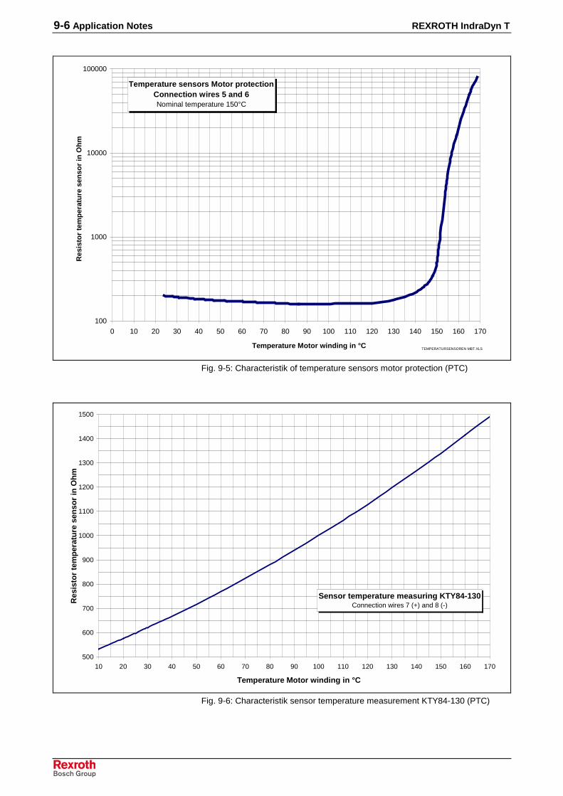
9-6 Application Notes REXROTH IndraDyn T
Temperature sensors Motor protectionConnection wires 5 and 6Nominal temperature 150°C
100
1000
10000
100000
0 10 20 30 40 50 60 70 80 90 100 110 120 130 140 150 160 170
Temperature Motor winding in °C
Res
isto
rte
mp
erat
ure
sen
sor
inO
hm
TEMPERATURSENSOREN MBT.XLS
Fig. 9-5: Characteristik of temperature sensors motor protection (PTC)
Sensor temperature measuring KTY84-130Connection wires 7 (+) and 8 (-)
500
600
700
800
900
1000
1100
1200
1300
1400
1500
10 20 30 40 50 60 70 80 90 100 110 120 130 140 150 160 170
Temperature Motor winding in °C
Res
isto
rte
mp
erat
ure
sen
sor
inO
hm
Fig. 9-6: Characteristik sensor temperature measurement KTY84-130 (PTC)
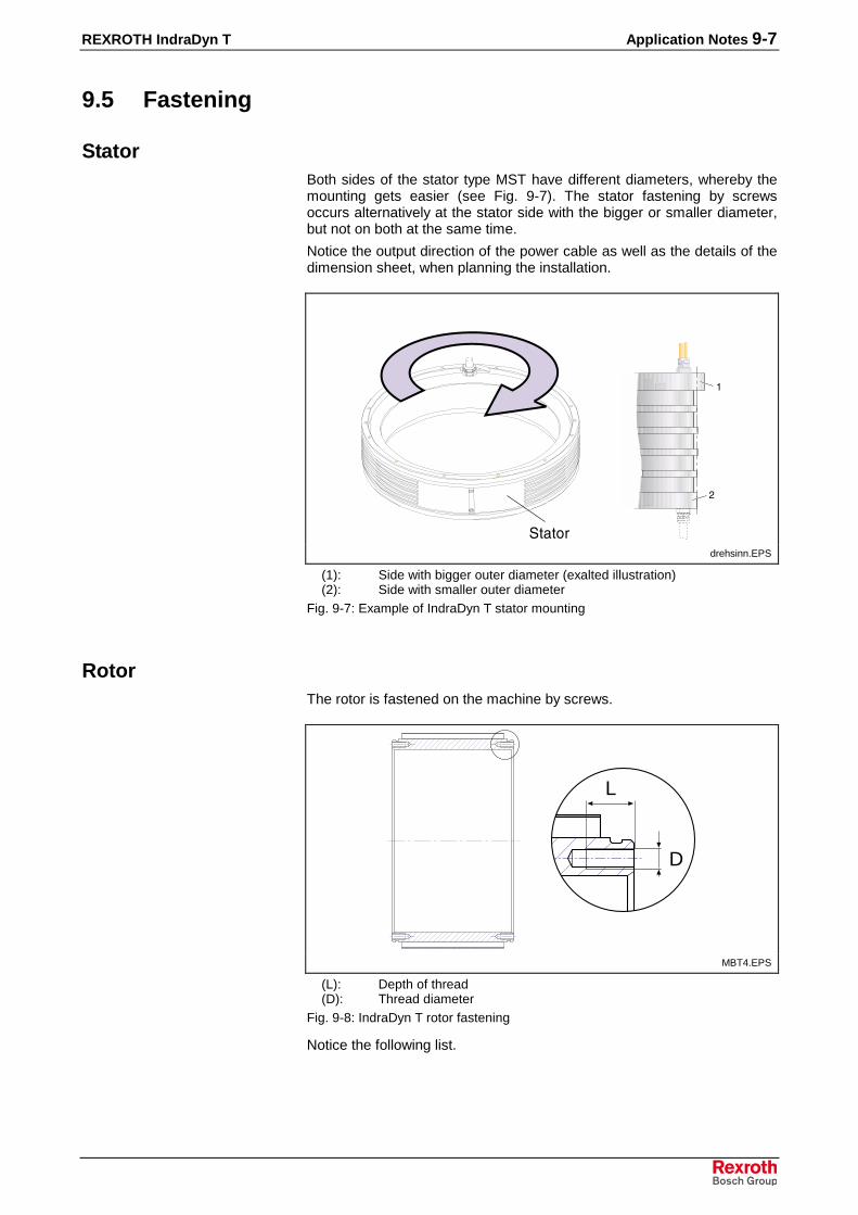
REXROTH IndraDyn T Application Notes 9-7
9.5 Fastening
StatorBoth sides of the stator type MST have different diameters, whereby themounting gets easier (see Fig. 9-7). The stator fastening by screwsoccurs alternatively at the stator side with the bigger or smaller diameter,but not on both at the same time.
Notice the output direction of the power cable as well as the details of thedimension sheet, when planning the installation.
�����
�
drehsinn.EPS
(1): Side with bigger outer diameter (exalted illustration)(2): Side with smaller outer diameter
Fig. 9-7: Example of IndraDyn T stator mounting
RotorThe rotor is fastened on the machine by screws.
L
D
MBT4.EPS
(L): Depth of thread(D): Thread diameter
Fig. 9-8: IndraDyn T rotor fastening
Notice the following list.
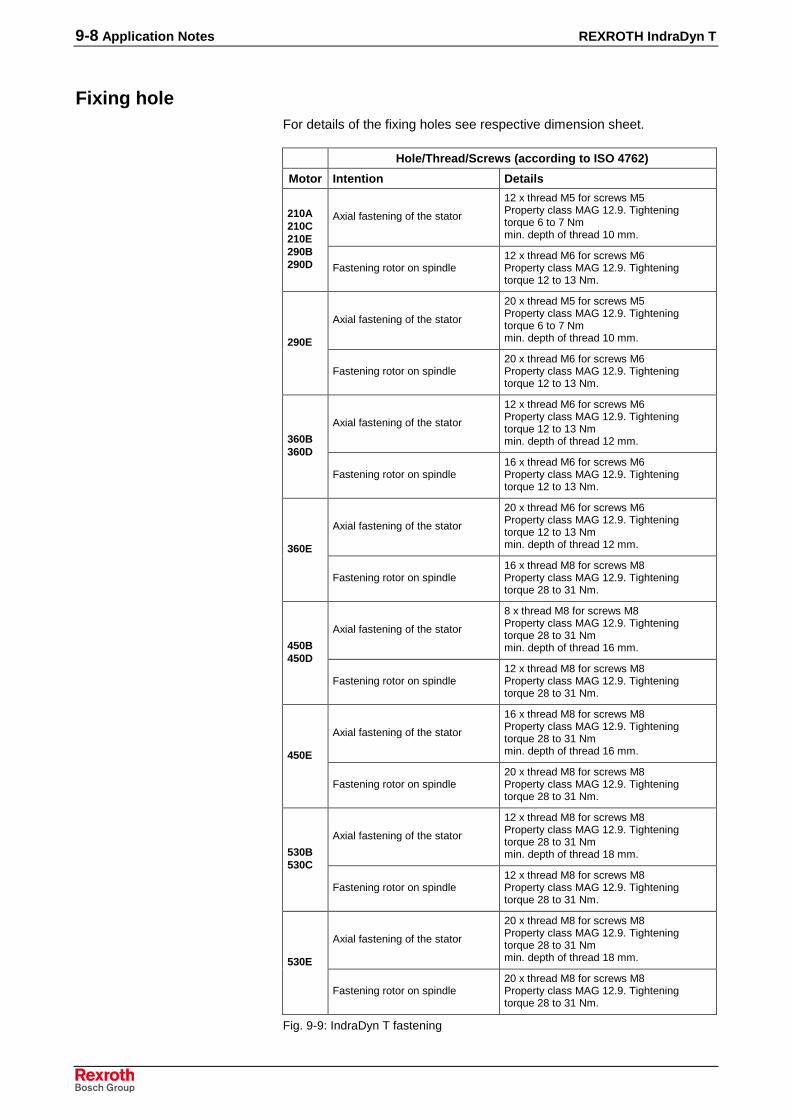
9-8 Application Notes REXROTH IndraDyn T
Fixing holeFor details of the fixing holes see respective dimension sheet.
Hole/Thread/Screws (according to ISO 4762)
Motor Intention Details
Axial fastening of the stator
12 x thread M5 for screws M5Property class MAG 12.9. Tighteningtorque 6 to 7 Nmmin. depth of thread 10 mm.
210A210C210E290B290D Fastening rotor on spindle
12 x thread M6 for screws M6Property class MAG 12.9. Tighteningtorque 12 to 13 Nm.
Axial fastening of the stator
20 x thread M5 for screws M5Property class MAG 12.9. Tighteningtorque 6 to 7 Nmmin. depth of thread 10 mm.290E
Fastening rotor on spindle20 x thread M6 for screws M6Property class MAG 12.9. Tighteningtorque 12 to 13 Nm.
Axial fastening of the stator
12 x thread M6 for screws M6Property class MAG 12.9. Tighteningtorque 12 to 13 Nmmin. depth of thread 12 mm.360B
360D
Fastening rotor on spindle16 x thread M6 for screws M6Property class MAG 12.9. Tighteningtorque 12 to 13 Nm.
Axial fastening of the stator
20 x thread M6 for screws M6Property class MAG 12.9. Tighteningtorque 12 to 13 Nmmin. depth of thread 12 mm.360E
Fastening rotor on spindle16 x thread M8 for screws M8Property class MAG 12.9. Tighteningtorque 28 to 31 Nm.
Axial fastening of the stator
8 x thread M8 for screws M8Property class MAG 12.9. Tighteningtorque 28 to 31 Nmmin. depth of thread 16 mm.450B
450D
Fastening rotor on spindle12 x thread M8 for screws M8Property class MAG 12.9. Tighteningtorque 28 to 31 Nm.
Axial fastening of the stator
16 x thread M8 for screws M8Property class MAG 12.9. Tighteningtorque 28 to 31 Nmmin. depth of thread 16 mm.450E
Fastening rotor on spindle20 x thread M8 for screws M8Property class MAG 12.9. Tighteningtorque 28 to 31 Nm.
Axial fastening of the stator
12 x thread M8 for screws M8Property class MAG 12.9. Tighteningtorque 28 to 31 Nmmin. depth of thread 18 mm.530B
530C
Fastening rotor on spindle12 x thread M8 for screws M8Property class MAG 12.9. Tighteningtorque 28 to 31 Nm.
Axial fastening of the stator
20 x thread M8 for screws M8Property class MAG 12.9. Tighteningtorque 28 to 31 Nmmin. depth of thread 18 mm.530E
Fastening rotor on spindle20 x thread M8 for screws M8Property class MAG 12.9. Tighteningtorque 28 to 31 Nm.
Fig. 9-9: IndraDyn T fastening

REXROTH IndraDyn T Application Notes 9-9
Note:
• The necessary screw length depends on the machineconstruction.
• The screwed connections must be able to take up both theforce due to the weight of the motor and the forces actingduring operation.
• Notice the minimum depth of thread for screwings on thestator type MST.
9.6 Drive End and Direction of Rotation
The assignment of drive end and direction of rotation for IndraDyn Tmotors depent on the output direction of the stator power cable.
Following illustrations explain the assignment:
�����
�
�
�
rotation_direction1.EPS
Fig. 9-10: Direction of rotation for stator type “...-xxCN-....“
�
�����
�
�
rotation_direction2.EPS
Fig. 9-11: Direction of rotation for stator type “...-xxSN-....“
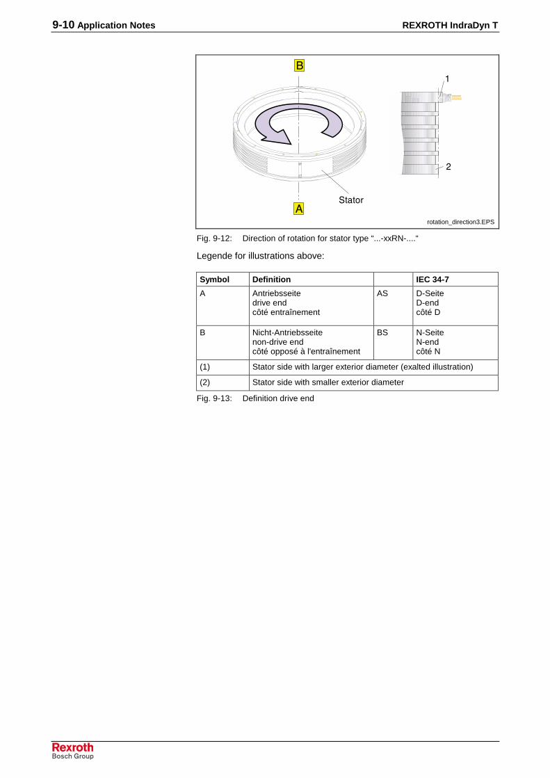
9-10 Application Notes REXROTH IndraDyn T
�
������
�
rotation_direction3.EPS
Fig. 9-12: Direction of rotation for stator type “...-xxRN-....“
Legende for illustrations above:
Symbol Definition IEC 34-7
A Antriebsseitedrive endcôté entraînement
AS D-SeiteD-endcôté D
B Nicht-Antriebsseitenon-drive endcôté opposé à l'entraînement
BS N-SeiteN-endcôté N
(1) Stator side with larger exterior diameter (exalted illustration)
(2) Stator side with smaller exterior diameter
Fig. 9-13: Definition drive end
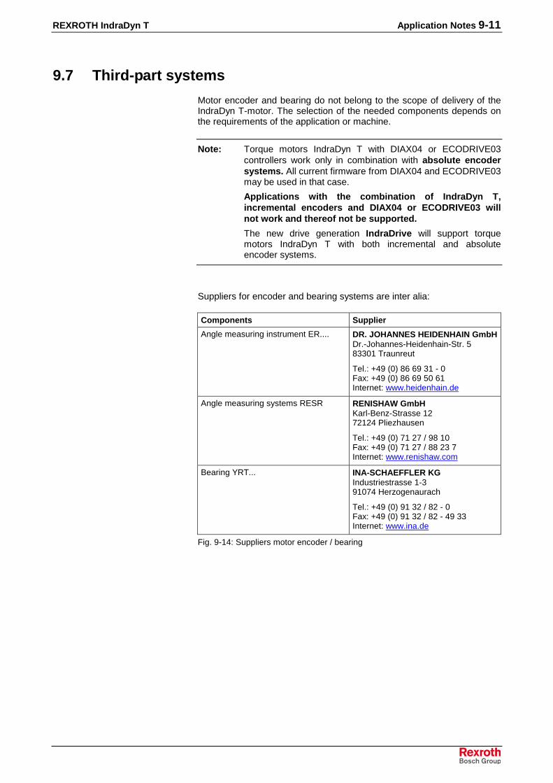
REXROTH IndraDyn T Application Notes 9-11
9.7 Third-part systems
Motor encoder and bearing do not belong to the scope of delivery of theIndraDyn T-motor. The selection of the needed components depends onthe requirements of the application or machine.
Note: Torque motors IndraDyn T with DIAX04 or ECODRIVE03controllers work only in combination with absolute encodersystems. All current firmware from DIAX04 and ECODRIVE03may be used in that case.
Applications with the combination of IndraDyn T,incremental encoders and DIAX04 or ECODRIVE03 willnot work and thereof not be supported.
The new drive generation IndraDrive will support torquemotors IndraDyn T with both incremental and absoluteencoder systems.
Suppliers for encoder and bearing systems are inter alia:
Components Supplier
Angle measuring instrument ER.... DR. JOHANNES HEIDENHAIN GmbHDr.-Johannes-Heidenhain-Str. 583301 Traunreut
Tel.: +49 (0) 86 69 31 - 0Fax: +49 (0) 86 69 50 61Internet: www.heidenhain.de
Angle measuring systems RESR RENISHAW GmbHKarl-Benz-Strasse 1272124 Pliezhausen
Tel.: +49 (0) 71 27 / 98 10Fax: +49 (0) 71 27 / 88 23 7Internet: www.renishaw.com
Bearing YRT... INA-SCHAEFFLER KGIndustriestrasse 1-391074 Herzogenaurach
Tel.: +49 (0) 91 32 / 82 - 0Fax: +49 (0) 91 32 / 82 - 49 33Internet: www.ina.de
Fig. 9-14: Suppliers motor encoder / bearing

9-12 Application Notes REXROTH IndraDyn T
Notes

REXROTH IndraDyn T Handling and Transport 10-1
10 Handling and Transport
10.1 Supplied Condition
IndraDyn T-motors are delivered in wooden crates. Packing units onpallets are secured by retaining straps.
CAUTION
Injuries due to uncontrolled movement of theretaining straps when cutting!⇒ Maintain a sufficient distance and carefully cut the
retaining straps.
At delivery the stator and rotor of the size 450 and 530 may be connectedwith an mounting ring During transport and storage, the mounting ringmust remain on the motor.
⇒ Remove the mounting ring only after finishing and testing of themounting.
⇒ Use the mounting ring for safety at dismounting and reconsignment.
The stators type MST of construction “...-ST-...” are protected withcorrosion protection wax RIVOLTA K.S.P. 317. The corrosions protectionhas to be kept for transport and storage.
The contact surface of this stators have to be cleaned with a suitablecleanser before mounting (e.g. RIVOLTA A.C.S.3).
Factory InspectionAll IndraDyn T-motors undergo the following inspections, among others,at the factory:
• High-voltage test according to EN 60034-1 (= VDE 0530-1).
• Insulation resistance according to EN 60204-1/1.92, Section 20.3.
• Geometric measurement of all mounting sizes.
Inspection by CustomerSince all IndraDyn T-motors undergo a standardized inspectionprocedure, high-voltage inspections by the customer are not required.Motors and components could be damaged if they undergo several high-voltage inspections.
CAUTION
Destruction of motor components by improperlyexecuted high-voltage inspection! Invalidationof warranty!⇒ Avoid repeated inspections.
⇒ Observe the regulations of EN 60034-1(= VDE 0530-1).

10-2 Handling and Transport REXROTH IndraDyn T
Scope of deliveryThe total scope of delivery can be seen in the delivery note or the waybill.The content, however, can consist of several packages. Each individualpackage can be identified using the shipment label attached on theoutside.
For both stator and rotor an individual type plate with unit marking andtechnical details is attached as well as a supply note with information forhandling.
For motors with an optional installation ring an additional delivery notewith further information is attached.
MBT5.JPG
Fig. 10-1: Scope of delivery
⇒ After receiving the goods, compare the ordered and the supplied type.Submit claims concerning differences immediately.
⇒ Check the received scope of delivery on its completeness.

REXROTH IndraDyn T Handling and Transport 10-3
10.2 Transport and Storage
Also observe the notes regarding storage and transport on the packages.
CAUTION
Damages or injuries and invalidation of thewarranty due to improper handling! Heavy!⇒ Strict observance of all security and warning
notices (see Chapter 3)!⇒ Protect the products from dampness and corrosion
⇒ Avoid mechanical stressing, strokes, throwing,tipping or dropping of the products.
⇒ Use only suitable hoisting gear.
⇒ Do never pick up a motor on the connectors, cablesor connection thread.
⇒ Use suitable protective equipment and protectiveclothing during transport.
⇒ Store the motors dry, vibration-free, dust-free andcorrosion-protected in horizontal conditionPermittable temperature range –20°C to +80 °C.
WARNING
The rotor is magnetically! Risk of injury andcrimping danger by magnetic forces!⇒ Eliminate movable metal objects or secure against
movement.⇒ Careful handling of magnetic parts.
CAUTION VORSICHTHazardous to sensitive parts!
Keep watches, credit cards, identification cardswith magnetic strips, magnetic tape andferromagnetic material (such as iron, nickel,and cobalt) away from magnetic parts.
Uhren, Kreditkarten, Scheckkarten und Ausweisemit Magnetstreifen sowie alle ferromagnetischeMetallteile wie Eisen, Nickel und Cobalt von den Permanentmagneten der Motorteile fernhalten.
Zerstörungsgefahr empfindlicher Teile!
WARNINGHealth hazard to people with heart pacemakers,metal implants and hearing aids when in proximityto these parts!
Strong magnetic fields due to permanent motormagnets!
Anyone with pacemakers, metal implants orhearing aids are not permitted to approach orto handle these motor parts.
If you have such conditions, consult with aphysician prior to handling these parts.
WARNUNG
Personen mit Herzschrittmachern, metallischenImplantaten oder Hörgeräten dürfen sich nichtdiesen Motorteilen nähern oder damit umgehen.
Besteht die Notwendigkeit für solche Personen,sich diesen Teilen zu nähern, so ist das zuvorvon einem Arzt zu entscheiden.
Gesundheitsgefahr für Personen mit Herzschrittma-chern, metallischen Implantaten oder Splittern undHörgeräten in unmittelbarer Umgebung dieser Teile!
Starkes Magnetfeld durch Permanentmagneteder Motorteile!
CAUTION VORSICHTHazardous to fingers and hands due to highattractive forces of permanent motor magnets!
Strong magnetic fields due to permanent motormagnets!
Handle only with protective gloves!Handle with extreme care.
Nur mit Schutzhandschuhen anfassen.Vorsichtig handhaben.
Quetschgefahr von Finger und Hand durch starkeAnziehungskräfte der Magnete!
Starkes Magnetfeld durch Permanentmagneteder Motorteile!
N
S
Mbt10.EPS
Fig. 10-2: Warning notices

10-4 Handling and Transport REXROTH IndraDyn T
Transport
�
����������������������������������� ��� ���������
����������������������������������� ���������
Mbt6.EPS
(1): Ring screw for transport (according to DIN 580)Fig. 10-3: IndraDyn T transport
Note:
• Use ring screws for transport only in opposite borings. Useonly suitable hoisting gear.
• Put down the motor only on clean, straight base in lyingposition.
• By damage of the fits on the cooling jacket the statorbecomes useless.
StorageStore the motor only according to the following figure.
Mbt7.EPS
Fig. 10-4: IndraDyn T storage
Note:
• Put down the motor only on clean, straight base in lyingposition.
• Before you store or ship the parts, remove the rests ofcoolant and other contamination.
• Use the transport crate to store the motor over a longertime and to protect it against damage and fouling.

REXROTH IndraDyn T Installation 11-1
11 Installation
11.1 Safety
WARNING
Injuries due to live parts! Lifting of heavy loads!Danger of damage!⇒ Carry out all working steps especially carefully. In
this way, you minimize the risk of accidents anddamages.
⇒ Use suitable lifting equipment, protective equipmentand protective clothing during transport.
⇒ Do not lift or move the motor by the loom of cables.
⇒ Install the motors only when they are not underpower and not connected electrically.
⇒ Observe the notes regarding safety and handlingnotes in previous chapters.
The volume and order of the here described steps can be affected by thecharacteristic of the machine construction and deviate from theschematically procedure. The following description only serves fororientation. Only the mounting instruction of the machine manufacturer isbinding.
11.2 Mounting ring
At delivery, the stator and rotor of the IndraDyn T motors of size 450 and530 are optionally connected with an mounting ring. The following figureshows the construction.
���������
���������
���
�
MBT8.EPS
(1): Fastening screw of the mounting ring(2): Boring for ring screws
Fig. 11-1: IndraDyn T mounting ring
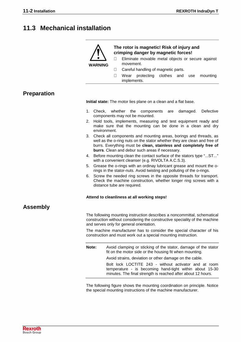
11-2 Installation REXROTH IndraDyn T
11.3 Mechanical installation
WARNING
The rotor is magnetic! Risk of injury andcrimping danger by magnetic forces!⇒ Eliminate movable metal objects or secure against
movement.⇒ Careful handling of magnetic parts.
⇒ Wear protecting clothes and use mountingimplements.
PreparationInitial state: The motor lies plane on a clean and a flat base.
1. Check, whether the components are damaged. Defectivecomponents may not be mounted.
2. Hold tools, implements, measuring and test equipment ready andmake sure that the mounting can be done in a clean and dryenvironment.
3. Check all components and mounting areas, borings and threads, aswell as the o-ring nuts on the stator whether they are clean and free ofburrs. Everything must be clean, stainless and completely free ofburrs. Clean and debur such areas if necessary.
4. Before mounting clean the contact surface of the stators type “...ST...”with a convenient cleanser (e.g. RIVOLTA A.C.S.3).
5. Grease the o-rings with an ordinay lubricant grease and mount the o-rings in the stator-nuts. Avoid twisting and polluting of the o-rings.
6. Screw the needed ring screws in the opposite threads for transport.Check the machine construction, whether longer ring screws with adistance tube are required.
Attend to cleanliness at all working steps!
AssemblyThe following mounting instruction describes a noncommittal, schematicalconstruction without considering the constructive speciality of the machineand serves only for general orientation.
The machine manufacturer has to consider the special character of hisconstruction and must work out a special mounting instruction.
Note: Avoid clamping or sticking of the stator, damage of the statorfit on the motor side or the housing fit when mounting.
Avoid strains, deviation or other damage on the cable.
Bolt lock LOCTITE 243 - without activator and at roomtemperature - is becoming hand-tight within about 15-30minutes. The final strength is reached after about 12 hours.
The following figure shows the mounting coordination on principle. Noticethe special mounting instructions of the machine manufacturer.

REXROTH IndraDyn T Installation 11-3
�
�
�
�
MBT9.EPS
(1): Lifting gear Right area of the picture.(2): Ring screw Stator mounted(3): Threaded rod with distance tube (4): O-ring on the stator(5): Machine component
Fig. 11-2: IndraDyn T installation
Initial state: The motor lies on a clean and a flat base. All previousdescribed steps were made.
Mount the motor according to the following schematical procedure.
1. Let the stator-rotor-package (optionally mounted with a mountingappliance) slide into the machine housing until the stator centeringleads the motor sufficient.
2. Tighten the fastening screws of stator and rotor hand-tight.3. Loosen the fastening screws of the installation ring on the stator (not
at the rotor).4. Center the rotor on the shaft.5. Lock the thread boring with LOCTITE 243 and tighten the fastening
screws of stator and rotor with a torque wrench.6. Loosen the fastening screws of the mounting appliance and remove
the mounting appliance.7. Check the precision and stability of all mounted parts and mechanical
connections.
After proper mechanical assembly, continue with the other connections.

11-4 Installation REXROTH IndraDyn T
11.4 Electrical Connection
Do the electrical connection of the motor according to the connectiondiagram and the instructions in chapter “Connection system”. Observe thenotes in the supplementary documentation.
Note:
• In the case of self-manufactured cables, pay attention thatthe design and installation are suitable for EMC.
• Notice the possibly needed fixings of the connectors andcables to the cable strain relief.
• The connection plans of the product documentation areused to generate the system circuit diagrams. Solely thesystem circuit diagrams of the machine manufacturer aredecisive for connecting the drive devices to the machine.
11.5 Coolant connection
Do the connection of the coolant supply for the motor according to theconnection diagrams from the machine manufacturer.
The whole coolant system has to be checked on density and deaerationbefore the start-up of the machine. Therefore, notice the instructions ofthe manufacturer.
Note:
• No force is allowed to influence the bolting over the supplycable.
• The connection plans of the product documentation areused to generate the system circuit diagrams. Solely thesystem circuit diagrams of the machine manufacturer aredecisive for connecting the drive devices to the machine.This is also guilty for the integration of systems forpressure reduction, flow and temperature control.
• The start-up of the coolant system is no part of the motorstart-up. Consider the notes of the machine and coolantsystem manufacturer.
REXROTH IndraDyn T Operating torque motors 12-1
12 Operating torque motors
12.1 Commissioning
CAUTION
Material damage due to errors in activatingmotors and moving elements! Unclear operatingstates and product data!⇒ Do not carry out commissioning if connections,
operating states or product data are unclear or faulty!⇒ Do not carry out commissioning if the safety and
monitoring equipment of the system is damaged ornot in operation.
⇒ It is not allowed to operate with damaged products!
⇒ Contact Rexroth for missing information or supportduring commissioning!
The following commission notes refer to the motors as part of a drive-system with drive and control devices.
Preparation1. Keep the documentation of all used products ready.2. Log all measures taken in the commissioning log.3. Check the products for damage.4. Check all mechanical and electrical connections.5. Observe the assigned direction of rotation for motor and encoder
when installing and programming the machine..6. Activate the safety and monitoring equipment of the system.
ExecutionWhen all prerequisites have been fulfilled, proceed as follows:
1. Activate the external coolant system to supply the motor and checkfor proper operations. Consider the notes of the manufacturer.
2. Carry out the commission of the drive-system according to theinstructions of the respective documentation. You can find therespective information in the functional description of the drivecontroller.
3. Log all measures taken in the commissioning log.
Commissioning of drive controllers and the control systems mayrequire additional steps. The inspection of the functioning andperformance of the systems is not part of the commissioning of the motor;instead, it is carried out within the commissioning of the machine entire.Observe the information and regulations of the machine manufacturer.

12-2 Operating torque motors REXROTH IndraDyn T
12.2 Deactivation
In the case of malfunctions, maintenance measures or to deactivatethe motors, proceed as follows:
1. Observe the instructions of the machine documentation.2. Use the machine-side control commands to bring the drive to a
controlled standstill.3. Switch off the power and control voltage of the drive controller.4. Switch off the master switch of the machine and deactivate external
systems accoring to the instructions of the manufacturer.5. Secure the machine against accidental movements and against
unauthorized operation.6. Wait for the discharge time of the electrical systems to expire and
disconnect all electrical connections if necessesary. Protect allelectrical cables and contacts against touching with other electricconducting parts.
7. Document all measures done in the start-up report and machinemaintenance plan.
12.3 Dismantling
DANGER
Fatal injury due to errors in activating motorsand moving elements!⇒ Do not work on unsecured and operating machines.
⇒ Secure the machine against accidental movementsand against unauthorized operation.
⇒ Before dismantling, secure the motor and feederagainst falling or movements before disconnectingthe mechanical connections.
1. Observe the instructions of the machine documentation.2. Please observe the safety notes and carry out all steps as described
in the previous section “Deactivation”.3. Before dismantling, secure the motor and supply lines against falling
or movements before disconnecting the mechanical connections.4. Empty the coolant duct of the motor and dismantle the motor from the
machine. Store the motor properly!5. Document all measures done in the start-up report and machine
maintenance plan.

REXROTH IndraDyn T Operating torque motors 12-3
12.4 Maintenance
Synchronous motors of the IndraDyn T series operate without wear withinthe given operating conditions. However, operation under unfavorableconditions can lead to limitations in availability.
⇒ Increase the availability with regular preventive maintenancemeasures. Notice the information in the maintenance schedule of themachine manufacturer and the described service measures.
⇒ Log all maintenance measures in the machine maintenance plan.
Measures
DANGER
Danger of injury due to moving elements!Danger of injury due to hot surfaces!⇒ Do not carry out any maintenance measures when
the machine is running.⇒ During maintenance work, secure the system
against restarting and unauthorized use.⇒ Do not work on hot surfaces.
Bosch Rexroth recommends the following maintenance measures, basedon the maintenance plan of the machine manufacturer:
Measure Interval
Check the function of the coolantsystem
According to the guidelines in themachine maintenance plan, but atleast every 1000 operating hours.
Check the mechanical and electricalconnections.
According to the guidelines in themachine maintenance plan, but atleast every 1000 operating hours.
Check the machine for smoothrunning, vibrations and bearing noises.
According to the guidelines in themachine maintenance plan, but atleast every 1000 operating hours.
Remove dust, chips and other dirtfrom the motor housing, cooling finsand the connections.
Depending on the degree of soiling,but after one operating year at thelatest.
Fig. 12-1: IndraDyn T maintenance measures
Coolant supplyIt may become necessary to dismantle the coolant supply formaintenance measure or troubleshooting.
⇒ This work must be carried out only by qualified personnel.⇒ Do not carry out any maintenance measures when the machine is
running. Please observe the safety instructions.⇒ Protect open supply cables and connections against penetration of
pollution.

12-4 Operating torque motors REXROTH IndraDyn T
12.5 Troubleshooting
DANGER
Danger of injury due to moving elements!Danger of injury due to hot surfaces!⇒ Do not carry out any maintenance measures when
the machine is running.⇒ Switch off the control-device and the machine and
await the discharging time of the electric systems⇒ During maintenance work, secure the system
against restarting and unauthorized use.⇒ Do not work on hot surfaces.
WARNING
The rotor is magnetic! Risk of injury andcrimping danger by magnetic forces!⇒ Eliminate movable metal objects or secure against
movement.⇒ Careful handling of magnetic parts.
⇒ Wear protecting clothes and use mountingimplements.
Possible causes for the malfunctioning of IndraDyn T-motors can belimited to the following areas:
• Motor-cooling circuit and temperature run
• Internal temperature sensor
• Mechanical damage of the motor
• Mechanical connection to machine
Encoder and temperature sensor are controlled by the drive controller orcontrol unit and are displayed according to the diagnosis. Observe thenotes in the corresponding documentation.
Subsequently some troubles are shown exemplary with potential reasons.This list does not lay claim to completeness.

REXROTH IndraDyn T Operating torque motors 12-5
Excess Temperature of Motor Housing
The housing temperature of the motor climbs to unusually high values.
CAUTION
Damage of motor or machine by restart afterraised motor temperature!⇒ Liquid cooled motors should not be reloaded
immediately or with cold coolant after loss of thecoolant system. Danger of damage!
⇒ Wait before you re-start until the motor temperaturedropped on 40°C.
1. Failure in the coolant system.
2. Original processing cycle has been changed.
3. Original motor parameters have been changed.
4. Motor bearings worn or defective.
1. Check the coolant system Clean or rinse the cooling circuit if required.Contact the machine manufacturer at malfunction of the coolantsystem.
2. Check the layout of the drive for changed requirements. If overloadingoccurs, stop operation. Danger of damage!
3. Reset to the original parameters. Check the sizing of the drive in thecase of changed requirements.
4. Contact the machine manufacturer.
High motor temperature values, but housing temperature is normal
The diagnostics system of the drive controller shows unusually highvalues for the winding temperature via the display or control software.However, the motor housing has a normal temperature.
1. Wiring error or cable break in sensor cable.
2. Diagnostics system defective.
3. Winding temperature sensor failure (PTC).
1. Check the wiring and connection of the temperature sensor accordingto the connection plan.
2. Check the diagnostics system on the device controller or the control.
3. Check the resistance value of the temperature sensor using amultimeter.
• Switch off the system and await the discharging time.
• Disconnect the connection of the temperature sensor on the control-device. Set the measuring instrument on resistor measuring andconnect the strand pair with the measuring instrument (therewith, thesensor cable is also checked). Check the values according to thecharacteristic curve in chapter “Application notes”.
Status
Possible causes
Measurements to
Status
Possible causes
Measurements to

12-6 Operating torque motors REXROTH IndraDyn T
Motor or machine generates vibrations
Audible or tactile vibrations occur on the motor or on the machine.
1. Driven machine elements are insufficiently coupled or damaged.
2. Motor bearings worn or defective. Available bearing life time orgrease life time elapsed.
3. Motor mount loose.
4. Drive system control loop is instable.
1. Contact the machine manufacturer.
2. Contact the machine manufacturer.
3. Check the mechanical connection. Do not continue to use damagedparts. Contact the machine manufacturer.
4. Check parameters of drive system (motor and encoder data).Observe the troubleshooting notes in the documentation for the drivecontroller.
Specified position is not attained
The positioning command of the control is not precisely executed – or notat all. No malfunction display on the drive controller or the control.
1. Wiring of encoder cable is incorrect or defective. Pin assignment(encoder signals) in cable or plug may be switched.
2. Insufficient shielding of encoder cable against interference.
3. Incorrect encoder parameters set in drive controller.
4. Motor-machine connection loose.
5. Encoder defective.
1. Check wiring according to connection plan and check state of cablesfor damage.
2. Check shielding; if necessary increase effective contact surfaces ofshielding.
3. Correct the parameters. Consult the commissioning log for originalvalues.
4. Check the mechanical connection. Do not continue to use damagedparts. Contact the machine manufacturer.
5. Change of encoder is necessary. Contact the machine manufacturer.
Status
Possible causes
Countermeasures
Status
Possible causes
Countermeasures

REXROTH IndraDyn T Service & Support 13-1
13 Service & Support
13.1 Helpdesk
Unser Kundendienst-Helpdesk im Hauptwerk Lohram Main steht Ihnen mit Rat und Tat zur Seite.Sie erreichen uns
Our service helpdesk at our headquarters in Lohr amMain, Germany can assist you in all kinds of inquiries.Contact us at:
- telefonisch - by phone: 49 (0) 9352 40 50 60über Service Call Entry Center Mo-Fr 07:00-18:00- via Service Call Entry Center Mo-Fr 7:00 am - 6:00 pm
- per Fax - by fax: +49 (0) 9352 40 49 41
- per e-Mail - by e-mail: [email protected]
13.2 Service-Hotline
Außerhalb der Helpdesk-Zeiten ist der Servicedirekt ansprechbar unter
After helpdesk hours, contact our servicedepartment directly at
+49 (0) 171 333 88 26
oder - or +49 (0) 172 660 04 06
13.3 Internet
Unter www.boschrexroth.de finden Sieergänzende Hinweise zu Service, Reparatur undTraining sowie die aktuellen Adressen *) unsererauf den folgenden Seiten aufgeführten Vertriebs-und Servicebüros.
Verkaufsniederlassungen
Niederlassungen mit Kundendienst
Außerhalb Deutschlands nehmen Sie bitte zuerst Kontakt mitunserem für Sie nächstgelegenen Ansprechpartner auf.
*) Die Angaben in der vorliegenden Dokumentation könnenseit Drucklegung überholt sein.
At www.boschrexroth.de you may findadditional notes about service, repairs and trainingin the Internet, as well as the actual addresses *) ofour sales- and service facilities figuring on thefollowing pages.
sales agencies
offices providing service
Please contact our sales / service office in your area first.
*) Data in this document may have become obsolete sinceprinting.
13.4 Vor der Kontaktaufnahme... - Before contacting us...
Wir können Ihnen schnell und effizient helfen wennSie folgende Informationen bereithalten:
1. detaillierte Beschreibung der Störung und derUmstände.
2. Angaben auf dem Typenschild der betreffendenProdukte, insbesondere Typenschlüssel undSeriennummern.
3. Tel.-/Faxnummern und e-Mail-Adresse, unterdenen Sie für Rückfragen zu erreichen sind.
For quick and efficient help, please have thefollowing information ready:
1. Detailed description of the failure andcircumstances.
2. Information on the type plate of the affectedproducts, especially type codes and serialnumbers.
3. Your phone/fax numbers and e-mail address,so we can contact you in case of questions.

13-2 Service & Support REXROTH IndraDyn T
13.5 Kundenbetreuungsstellen - Sales & Service Facilities
Deutschland – Germany vom Ausland: (0) nach Landeskennziffer weglassen!from abroad: don’t dial (0) after country code!
Vertriebsgebiet MitteGermany Centre
Rexroth Indramat GmbHBgm.-Dr.-Nebel-Str. 2 / Postf. 135797816 Lohr am Main / 97803 Lohr
Kompetenz-Zentrum Europa
Tel.: +49 (0)9352 40-0Fax: +49 (0)9352 40-4885
S E R V I C E
C A L L E N T R Y C E N T E RMO – FR
von 07:00 - 18:00 Uhr
from 7 am – 6 pm
Tel. +49 (0) 9352 40 50 [email protected]
S E R V I C E
HOTLINEMO – FR
von 17:00 - 07:00 Uhrfrom 5 pm - 7 am
+ SA / SO
Tel.: +49 (0)172 660 04 06oder / or
Tel.: +49 (0)171 333 88 26
S E R V I C E
ERSATZTEILE / SPARESverlängerte Ansprechzeit- extended office time -
♦ nur an Werktagen- only on working days -
♦ von 07:00 - 18:00 Uhr- from 7 am - 6 pm -
Tel. +49 (0) 9352 40 42 22
Vertriebsgebiet SüdGermany South
Rexroth Indramat GmbHLandshuter Allee 8-1080637 München
Tel.: +49 (0)89 127 14-0Fax: +49 (0)89 127 14-490
Vertriebsgebiet WestGermany West
Bosch Rexroth AGRegionalzentrum WestBorsigstrasse 1540880 Ratingen
Tel.: +49 (0)2102 409-0Fax: +49 (0)2102 409-406
Gebiet SüdwestGermany South-West
Bosch Rexroth AGService-Regionalzentrum Süd-WestSiemensstr.170736 Fellbach
Tel.: +49 (0)711 51046–0Fax: +49 (0)711 51046–248
Gebiet SüdwestGermany South-West
Bosch Rexroth AGRegionalzentrum SüdwestRingstrasse 70 / Postfach 114470736 Fellbach / 70701 Fellbach
Tel.: +49 (0)711 57 61–100Fax: +49 (0)711 57 61–125
Vertriebsgebiet NordGermany North
Bosch Rexroth AGWalsroder Str. 9330853 Langenhagen
Tel.: +49 (0) 511 72 66 57-0Service: +49 (0) 511 72 66 57-256Fax: +49 (0) 511 72 66 57-93Service: +49 (0) 511 72 66 57-95
Vertriebsgebiet MitteGermany Centre
Bosch Rexroth AGRegionalzentrum MitteWaldecker Straße 1364546 Mörfelden-Walldorf
Tel.: +49 (0) 61 05 702-3Fax: +49 (0) 61 05 702-444
Vertriebsgebiet OstGermany East
Bosch Rexroth AGBeckerstraße 3109120 Chemnitz
Tel.: +49 (0)371 35 55-0Fax: +49 (0)371 35 55-333
Vertriebsgebiet OstGermany East
Bosch Rexroth AGRegionalzentrum OstWalter-Köhn-Str. 4d04356 Leipzig
Tel.: +49 (0)341 25 61-0Fax: +49 (0)341 25 61-111

REXROTH IndraDyn T Service & Support 13-3
Europa (West) - Europe (West)
vom Ausland: (0) nach Landeskennziffer weglassen, Italien: 0 nach Landeskennziffer mitwählenfrom abroad: don’t dial (0) after country code, Italy: dial 0 after country code
Austria - Österreich
Bosch Rexroth GmbHBereich IndramatStachegasse 131120 Wien
Tel.: +43 (0)1 985 25 40Fax: +43 (0)1 985 25 40-93
Austria – Österreich
Bosch Rexroth GmbHGesch.ber. Rexroth IndramatIndustriepark 184061 Pasching
Tel.: +43 (0)7221 605-0Fax: +43 (0)7221 605-21
Belgium - Belgien
Bosch Rexroth AGElectric Drives & ControlsIndustrielaan 81740 TernatTel.: +32 (0)2 5830719- service: +32 (0)2 5830717Fax: +32 (0)2 [email protected]
Denmark - Dänemark
BEC A/SZinkvej 68900 Randers
Tel.: +45 (0)87 11 90 60Fax: +45 (0)87 11 90 61
Great Britain – Großbritannien
Bosch Rexroth Ltd.Rexroth Indramat DivisionBroadway Lane, South CerneyCirencester, Glos GL7 5UH
Tel.: +44 (0)1285 863000Fax: +44 (0)1285 [email protected]@boschrexroth.co.uk
Finland - Finnland
Bosch Rexroth OyRexroth Indramat divisionAnsatie 6017 40 Vantaa
Tel.: +358 (0)9 84 91-11Fax: +358 (0)9 84 91-13 60
France - Frankreich
Bosch Rexroth S.A.Division Rexroth IndramatAvenue de la Trentaine(BP. 74)77503 Chelles Cedex
Tel.: +33 (0)164 72-70 00Fax: +33 (0)164 72-63 00Hotline: +33 (0)608 33 43 28
France - Frankreich
Bosch Rexroth S.A.Division Rexroth IndramatZI de Thibaud, 20 bd. Thibaud(BP. 1751)31084 Toulouse
Tel.: +33 (0)5 61 43 61 87Fax: +33 (0)5 61 43 94 12
France - Frankreich
Bosch Rexroth S.A.Division Rexroth Indramat91, Bd. Irène Joliot-Curie69634 Vénissieux – Cedex
Tel.: +33 (0)4 78 78 53 65Fax: +33 (0)4 78 78 53 62
Italy - Italien
Bosch Rexroth S.p.A.Via G. Di Vittoria, 120063 Cernusco S/N.MI
Tel.: +39 02 92 365 1+39 02 92 365 326
Fax: +39 02 92 365 500+39 02 92 365 516378
Italy - Italien
Bosch Rexroth S.p.A.Via Paolo Veronesi, 25010148 Torino
Tel.: +39 011 224 88 11Fax: +39 011 224 88 30
Italy - Italien
Bosch Rexroth S.p.A.Via del Progresso, 16 (Zona Ind.)35020 Padova
Tel.: +39 049 8 70 13 70Fax: +39 049 8 70 13 77
Italy - Italien
Bosch Rexroth S.p.A.Via Mascia, 180053 Castellamare di Stabia NA
Tel.: +39 081 8 71 57 00Fax: +39 081 8 71 68 85
Italy - Italien
Bosch Rexroth S.p.A.Viale Oriani, 38/A40137 Bologna
Tel.: +39 051 34 14 14Fax: +39 051 34 14 22
Netherlands – Niederlande/Holland
Bosch Rexroth B.V.Kruisbroeksestraat 1(P.O. Box 32)5281 RV Boxtel
Tel.: +31 (0)411 65 19 51Fax: +31 (0)411 65 14 83www.boschrexroth.nl
Netherlands - Niederlande/Holland
Bosch Rexroth Services B.V.Technical ServicesKruisbroeksestraat 1(P.O. Box 32)5281 RV Boxtel
Tel.: +31 (0)411 65 19 51Fax: +31 (0)411 67 78 [email protected]
Norway - Norwegen
Bosch Rexroth ASRexroth Indramat DivisionBerghagan 1 or: Box 30071405 Ski-Langhus 1402 Ski
Tel.: +47 (0)64 86 41 00Fax: +47 (0)64 86 90 [email protected]
Spain - Spanien
Bosch Rexroth S.A.Divisiòn Rexroth IndramatCentro Industrial SantigaObradors s/n08130 Santa Perpetua de MogodaBarcelona
Tel.: +34 9 37 47 94 00Fax: +34 9 37 47 94 01
Spain – Spanien
Goimendi S.A.División Rexroth IndramatParque Empresarial ZuatzuC/ Francisco Grandmontagne no.220018 San Sebastian
Tel.: +34 9 43 31 84 21- service: +34 9 43 31 84 56Fax: +34 9 43 31 84 27- service: +34 9 43 31 84 [email protected]
Sweden - Schweden
Rexroth Mecman Svenska ABRexroth Indramat Division- Varuvägen 7(Service: Konsumentvägen 4, Älfsjö)125 81 Stockholm
Tel.: +46 (0)8 727 92 00Fax: +46 (0)8 647 32 77
Sweden - Schweden
Rexroth Mecman Svenska ABIndramat SupportEkvändan 7254 67 Helsingborg
Tel.: +46 (0) 42 38 88 -50Fax: +46 (0) 42 38 88 -74
Switzerland West - Schweiz West
Bosch Rexroth Suisse SADépartement Rexroth IndramatRue du village 11020 Renens
Tel.: +41 (0)21 632 84 20Fax: +41 (0)21 632 84 21
Switzerland East - Schweiz Ost
Bosch Rexroth Schweiz AGGeschäftsbereich IndramatHemrietstrasse 28863 ButtikonTel. +41 (0) 55 46 46 111Fax +41 (0) 55 46 46 222
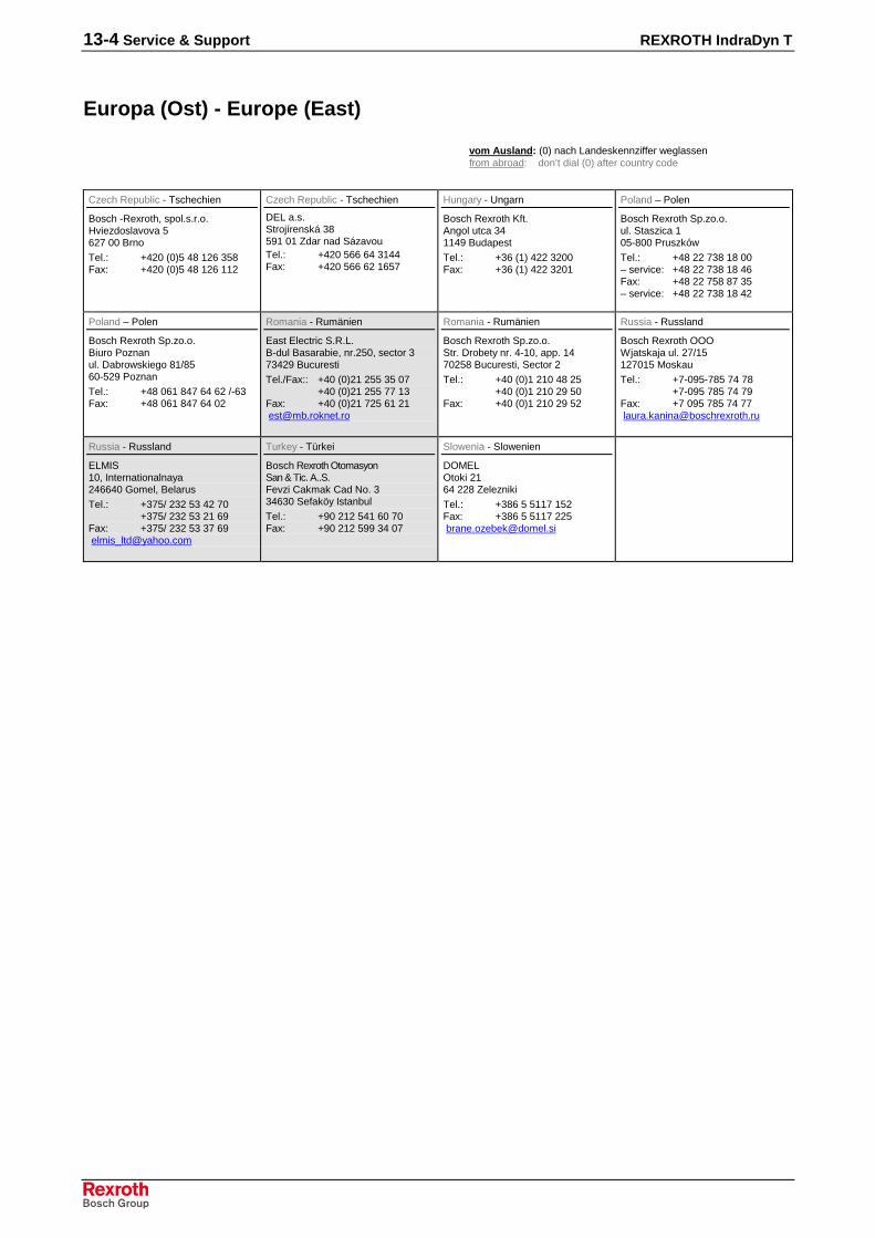
13-4 Service & Support REXROTH IndraDyn T
Europa (Ost) - Europe (East)
vom Ausland: (0) nach Landeskennziffer weglassenfrom abroad: don’t dial (0) after country code
Czech Republic - Tschechien
Bosch -Rexroth, spol.s.r.o.Hviezdoslavova 5627 00 Brno
Tel.: +420 (0)5 48 126 358Fax: +420 (0)5 48 126 112
Czech Republic - Tschechien
DEL a.s.Strojírenská 38591 01 Zdar nad SázavouTel.: +420 566 64 3144Fax: +420 566 62 1657
Hungary - Ungarn
Bosch Rexroth Kft.Angol utca 341149 Budapest
Tel.: +36 (1) 422 3200Fax: +36 (1) 422 3201
Poland – Polen
Bosch Rexroth Sp.zo.o.ul. Staszica 105-800 Pruszków
Tel.: +48 22 738 18 00– service: +48 22 738 18 46Fax: +48 22 758 87 35– service: +48 22 738 18 42
Poland – Polen
Bosch Rexroth Sp.zo.o.Biuro Poznanul. Dabrowskiego 81/8560-529 Poznan
Tel.: +48 061 847 64 62 /-63Fax: +48 061 847 64 02
Romania - Rumänien
East Electric S.R.L.B-dul Basarabie, nr.250, sector 373429 Bucuresti
Tel./Fax:: +40 (0)21 255 35 07+40 (0)21 255 77 13
Fax: +40 (0)21 725 61 [email protected]
Romania - Rumänien
Bosch Rexroth Sp.zo.o.Str. Drobety nr. 4-10, app. 1470258 Bucuresti, Sector 2
Tel.: +40 (0)1 210 48 25+40 (0)1 210 29 50
Fax: +40 (0)1 210 29 52
Russia - Russland
Bosch Rexroth OOOWjatskaja ul. 27/15127015 Moskau
Tel.: +7-095-785 74 78+7-095 785 74 79
Fax: +7 095 785 74 [email protected]
Russia - Russland
ELMIS10, Internationalnaya246640 Gomel, Belarus
Tel.: +375/ 232 53 42 70+375/ 232 53 21 69
Fax: +375/ 232 53 37 [email protected]
Turkey - Türkei
Bosch Rexroth OtomasyonSan & Tic. A..S.Fevzi Cakmak Cad No. 334630 Sefaköy Istanbul
Tel.: +90 212 541 60 70Fax: +90 212 599 34 07
Slowenia - Slowenien
DOMELOtoki 2164 228 Zelezniki
Tel.: +386 5 5117 152Fax: +386 5 5117 [email protected]

REXROTH IndraDyn T Service & Support 13-5
Africa, Asia, Australia – incl. Pacific Rim
Australia - Australien
AIMS - Australian IndustrialMachinery Services Pty. Ltd.28 Westside DriveLaverton North Vic 3026Melbourne
Tel.: +61 3 93 243 321Fax: +61 3 93 243 329Hotline: +61 4 19 369 [email protected]
Australia - Australien
Bosch Rexroth Pty. Ltd.No. 7, Endeavour WayBraeside Victoria, 31 95Melbourne
Tel.: +61 3 95 80 39 33Fax: +61 3 95 80 17 [email protected]
China
Shanghai Bosch RexrothHydraulics & Automation Ltd.Waigaoqiao, Free Trade ZoneNo.122, Fu Te Dong Yi RoadShanghai 200131 - P.R.China
Tel.: +86 21 58 66 30 30Fax: +86 21 58 66 55 [email protected][email protected]
China
Shanghai Bosch RexrothHydraulics & Automation Ltd.4/f, Marine TowerNo.1, Pudong AvenueShanghai 200120 - P.R.China
Tel: +86 21 68 86 15 88Fax: +86 21 58 40 65 77
China
Bosch Rexroth China Ltd.15/F China World Trade Center1, Jianguomenwai AvenueBeijing 100004, P.R.China
Tel.: +86 10 65 05 03 80Fax: +86 10 65 05 03 79
China
Bosch Rexroth China Ltd.Guangzhou Repres. OfficeRoom 1014-1016, Metro Plaza,Tian He District, 183 Tian He Bei RdGuangzhou 510075, P.R.China
Tel.: +86 20 8755-0030+86 20 8755-0011
Fax: +86 20 8755-2387
China
Bosch Rexroth (China) Ltd.A-5F., 123 Lian Shan StreetSha He Kou DistrictDalian 116 023, P.R.China
Tel.: +86 411 46 78 930Fax: +86 411 46 78 932
China
Melchers GmbHBRC-SE, Tightening & Press-fit13 Floor Est Ocean CentreNo.588 Yanan Rd. East65 Yanan Rd. WestShanghai 200001
Tel.: +86 21 6352 8848Fax: +86 21 6351 3138
Hongkong
Bosch Rexroth (China) Ltd.6th Floor,Yeung Yiu Chung No.6 Ind Bldg.19 Cheung Shun StreetCheung Sha Wan,Kowloon, Hongkong
Tel.: +852 22 62 51 00Fax: +852 27 41 33 44
India - Indien
Bosch Rexroth (India) Ltd.Rexroth Indramat DivisionPlot. A-58, TTC Industrial AreaThane Turbhe Midc RoadMahape VillageNavi Mumbai - 400 701
Tel.: +91 22 7 61 46 22Fax: +91 22 7 68 15 31
India - Indien
Bosch Rexroth (India) Ltd.Rexroth Indramat DivisionPlot. 96, Phase IIIPeenya Industrial AreaBangalore - 560058
Tel.: +91 80 41 70 211Fax: +91 80 83 94 345
India - Indien
Bosch Rexroth (India) Ltd.1st Floor, S-10Green Park ext. MarketNew Delhi – 110016
Tel.: +91 1 16 56 68 88Fax: +91 1 16 56 68 87
Indonesia - Indonesien
PT. Rexroth WijayakusumaBuilding # 202, CilandakCommercial EstateJl. Cilandak KKO, Jakarta 12560
Tel.: +62 21 7891169 (5 lines)Fax: +62 21 7891170 - 71
Japan
Bosch Rexroth Automation Corp.Service Center JapanYutakagaoka 1810, Meito-ku,NAGOYA 465-0035, Japan
Tel.: +81 52 777 88 41+81 52 777 88 53+81 52 777 88 79
Fax: +81 52 777 89 01
Japan
Bosch Rexroth Automation Corp.Rexroth Indramat Division1F, I.R. BuildingNakamachidai 4-26-44, Tsuzuki-kuYOKOHAMA 224-0041, Japan
Tel.: +81 45 942 72 10Fax: +81 45 942 03 41
Korea
Bosch Rexroth-Korea Ltd.Electric Drives and ControlsBongwoo Bldg. 7FL, 31-7, 1GaJangchoong-dong, Jung-guSeoul, 100-391
Tel.: +82 234 061 813Fax: +82 222 641 295
Korea
Bosch Rexroth-Korea Ltd.1515-14 Dadae-Dong, Saha-KuRexroth Indramat DivisionPusan Metropolitan City, 604-050
Tel.: +82 51 26 00 741Fax: +82 51 26 00 [email protected]
Malaysia
Bosch Rexroth Sdn.Bhd.11, Jalan U8/82, Seksyen U840150 Shah AlamSelangor, Malaysia
Tel.: +60 3 78 44 80 00Fax: +60 3 78 45 48 [email protected]@tm.net.my
Singapore - Singapur
Bosch Rexroth Pte Ltd15D Tuas RoadSingapore 638520
Tel.: +65 68 61 87 33Fax: +65 68 61 18 25sanjay.nemade
@boschrexroth.com.sg
South Africa - Südafrika
TECTRA Automation (Pty) Ltd.71 Watt Street, MeadowdaleEdenvale 1609
Tel.: +27 11 971 94 00Fax: +27 11 971 94 40Hotline: +27 82 903 29 [email protected]
Taiwan
Rexroth Uchida Co., Ltd.No.17, Alley 24, Lane 737Cheng Bei 1 Rd., YungkangTainan Hsien
Tel.: +886 6 25 36 565Fax: +886 6 25 34 [email protected]
Thailand
NC Advance Technology Co. Ltd.59/76 Moo 9Ramintra road 34Tharang, Bangkhen,Bangkok 10230
Tel.: +66 2 943 70 62+66 2 943 71 21
Fax: +66 2 509 23 [email protected]

13-6 Service & Support REXROTH IndraDyn T
Nordamerika – North AmericaUSAHeadquarters - Hauptniederlassung
Bosch Rexroth CorporationElectric Drives and Controls5150 Prairie Stone ParkwayHoffman Estates, IL 60192-3707
Tel.: +1 847 645-3600Fax: +1 847 [email protected]@boschrexroth-us.com
USA Central Region - Mitte
Bosch Rexroth CorporationRexroth Indramat DivisionCentral Region Technical Center1701 Harmon RoadAuburn Hills, MI 48326
Tel.: +1 248 393-3330Fax: +1 248 393-2906
USA Southeast Region - Südwest
Bosch Rexroth CorporationRexroth Indramat DivisionSoutheastern Technical Center3625 Swiftwater Park DriveSuwanee, GA 30124
Tel.: +1 770 932-3200Fax: +1 770 932-1903
USA SERVICE-HOTLINE
- 7 days x 24hrs -
+1-800-860-10551 800 REXROTH
USA East Region – Ost
Bosch Rexroth CorporationRexroth Indramat DivisionCharlotte Regional Sales Office14001 South Lakes DriveCharlotte, North Carolina 28273
Tel.: +1 704 5 83 97 62+1 704 5 83 14 86
USA Northeast Region – Nordost
Bosch Rexroth CorporationRexroth Indramat DivisionNortheastern Technical Center99 Rainbow RoadEast Granby, Connecticut 06026
Tel.: +1 860 8 44 83 77Fax: +1 860 8 44 85 95
USA West Region – West
Bosch Rexroth Corporation7901 Stoneridge Drive, Suite 220Pleasant Hill, California 94588
Tel.: +1 925 227 10 84Fax: +1 925 227 10 81
Canada East - Kanada Ost
Bosch Rexroth Canada CorporationBurlington Division3426 Mainway DriveBurlington, OntarioCanada L7M 1A8
Tel.: +1 905 335 55 11Fax: +1 905 335-41 [email protected]
Canada West - Kanada West
Bosch Rexroth Canada Corporation5345 Goring St.Burnaby, British ColumbiaCanada V7J 1R1
Tel. +1 604 205-5777Fax +1 604 [email protected]
Mexico
Bosch Rexroth Mexico S.A. de C.V.Calle Neptuno 72Unidad Ind. Vallejo07700 Mexico, D.F.
Tel.: +52 5 754 17 11+52 5 754 36 84+52 5 754 12 60
Fax: +52 5 754 50 73+52 5 752 59 43
Mexico
Bosch Rexroth S.A. de C.V.Calle Argentina No 3913Fracc. las Torres64930 Monterrey, N.L.
Tel.: +52 8 333 88 34...36+52 8 349 80 91...93
Fax: +52 8 346 78 [email protected]
Südamerika – South AmericaArgentina - Argentinien
Bosch Rexroth S.A.I.C."The Drive & Control Company"Acassusso 48 41/471605 MunroProvincia de Buenos Aires
Tel.: +54 11 4756 01 40Fax: +54 11 4756 01 [email protected]
Argentina - Argentinien
NAKASEServicio Tecnico CNCCalle 49, No. 5764/66B1653AOX Villa BalesterProvincia de Buenos Aires
Tel.: +54 11 4768 36 43Fax: +54 11 4768 24 [email protected]@[email protected] (Service)
Brazil - Brasilien
Bosch Rexroth Ltda.Av. Tégula, 888Ponte Alta, Atibaia SPCEP 12942-440
Tel.: +55 11 4414 56 92+55 11 4414 56 84
Fax sales: +55 11 4414 57 07Fax serv.: +55 11 4414 56 [email protected]
Brazil - Brasilien
Bosch Rexroth Ltda.R. Dr.Humberto Pinheiro Vieira, 100Distrito Industrial [Caixa Postal 1273]89220-390 Joinville - SC
Tel./Fax: +55 47 473 58 33Mobil: +55 47 9974 [email protected]
Columbia - Kolumbien
Reflutec de Colombia Ltda.Calle 37 No. 22-31Santafé de Bogotá, D.C.Colombia
Tel.: +57 1 368 82 67+57 1 368 02 59
Fax: +57 1 268 97 [email protected]@007mundo.com

REXROTH IndraDyn T Index 14-1
14 Index
AApplication notes 9-1Appropriate use
Introduction 2-1Uses 2-2
CCommissioning 12-1Conditions for use 9-1Connecting cable 8-2Connection system 8-1Connection System
Encoder 8-6Connection with coupling 8-5Connection with terminal box 8-3Corrosion 10-3
DData sheet
size 210 4-4size 290 4-6size 360 4-8size 450 4-10size 530 4-12
Deactivation 12-2Definitions 4-1Degree of Protection 9-4dimension sheet mounting ring 7-3Dimensions size MBT210 5-2Dimensions size MBT290 5-12Dimensions size MBT360 5-22Dimensions size MBT450 5-33Dimensions size MBT530 5-43discharge time 12-2Dismantling 12-2Drive End 9-9
FFrame length 6-1, 6-2Frame shape 6-2
HHandling 10-1High-voltage test, also see Inspection 10-1
IInappropriate use 2-2
Consequences, Discharge of liability 2-1Inspection
High-voltage inspection 10-1Installation
Coolant connection 11-4Electrical connection 11-4Installation ring 11-1Mechanical installation 11-2Safety 11-1
Insulation resistance 10-1Introduction to the product 1-1
14-2 Index REXROTH IndraDyn T
MMaintenance 12-3Maximum speed 4-2Moment of inertia of the rotor 4-2Motor characteristic curve MBT210 4-5Motor characteristic curve MBT290 4-7Motor characteristic curve MBT360 4-9Motor characteristic curve MBT450 4-11Motor characteristic curve MBT530 4-13Motor cooling 8-7, 9-2Motor temperature control 9-5Mounting ring 7-1
OON time 4-1Operating behavior 4-3Operating characteristic 4-3Operating modes 4-1Operating pressure 8-7
PParameters 4-2
RRated output 4-2Rated speed 4-2Rated torque 4-2
SSafety Instructions for Electric Drives and Controls 3-1Storage 10-3Supplied Condition 10-1
TThermal time constant 4-2Torque constant 4-2Transport 10-1, 10-3Troubleshooting 12-4Type code
Rotor MRT210 6-3Rotor MRT290 6-5Rotor MRT360 6-6Rotor MRT450 6-7Rotor MRT530 6-8Stator MST210 6-4Stator MST290 6-5Stator MST360 6-6Stator MST450 6-7Stator MST530 6-8
Type code rotor MRT 6-1Type code stator MST 6-1
UUse See appropriate use and inappropriate use
WWinding resistance 4-2

REXROTH IndraDyn T Index 14-3

14-4 Index REXROTH IndraDyn T


Bosch Rexroth AGElectric Drives and ControlsBgm.-Dr.-Nebel-Str. 297816 Lohr a. Main, [email protected]
298798 Printed in GermanyDOK-MOTOR*-MBT********-PR02-EN-P