Rexroth IndraDyn S Edition 03 Synchronous Motors QSK061 ...
90
Project Planning Manual Electric Drives and Controls Pneumatics Service Linear Motion and Assembly Technologies Hydraulics Rexroth IndraDyn S Synchronous Motors QSK061, -075, -100 R911330321 Edition 03
Transcript of Rexroth IndraDyn S Edition 03 Synchronous Motors QSK061 ...

Project Planning Manual
Electric Drivesand Controls Pneumatics Service
Linear Motion and Assembly TechnologiesHydraulics
Rexroth IndraDyn SSynchronous MotorsQSK061, -075, -100
R911330321Edition 03

Rexroth IndraDyn SSynchronous MotorsQSK061, -075, -100
Project Planning Manual
DOK-MOTOR*-QSK********-PR03-EN-P
RS-ba06b1c1239a6f210a6846a0013ec750-3-en-US-4
Edition Release Date Notes
DOK-MOTOR*-QSK********-PR01-EN-P 10.2009 First editionDOK-MOTOR*-QSK********-PR02-EN-P 05.2011 AmendmentDOK-MOTOR*-QSK********-PR03-EN-P 12.2012 Amendment QSK100B
Copyright © Bosch Rexroth AG 2012This document, as well as the data, specifications and other information setforth in it, are the exclusive property of Bosch Rexroth AG. It may not be re‐produced or given to third parties without its consent.
Liability The specified data is intended for product description purposes only and shallnot be deemed to be a guaranteed characteristic unless expressly stipulatedin the contract. All rights are reserved with respect to the content of this docu‐mentation and the availability of the product.
Published by Bosch Rexroth AGBgm.-Dr.-Nebel-Str. 2 ■ 97816 Lohr a. Main, GermanyPhone +49 9352 18 0 ■ Fax +49 9352 18 8400http://www.boschrexroth.com/Dept. DC-IA/EDM (jw/mb)
Note This document has been printed on chlorine-free bleached paper.
Title
Type of Documentation
Document Typecode
Internal File Reference
Record of Revision
Bosch Rexroth AG DOK-MOTOR*-QSK********-PR03-EN-P Rexroth IndraDyn S Synchronous Motors QSK061, -075, -100

Table of ContentsPage
1 Important Instructions on Use........................................................................................ 51.1 Intended Use ......................................................................................................................................... 51.1.1 Introduction.......................................................................................................................................... 51.1.2 Areas of Use and Application.............................................................................................................. 51.2 Inappropriate Use................................................................................................................................... 6
2 Safety Instructions for Electric Drives and Controls....................................................... 72.1 Definitions of Terms................................................................................................................................ 72.2 General Information................................................................................................................................ 82.2.1 Using the Safety Instructions and Passing Them on to Others........................................................... 82.2.2 Requirements for Safe Use................................................................................................................. 82.2.3 Hazards by Improper Use.................................................................................................................... 92.3 Instructions with Regard to Specific Dangers....................................................................................... 102.3.1 Protection Against Contact With Electrical Parts and Housings........................................................ 102.3.2 Protective Extra-Low Voltage as Protection Against Electric Shock ................................................ 112.3.3 Protection Against Dangerous Movements....................................................................................... 122.3.4 Protection Against Magnetic and Electromagnetic Fields During Operation and Mounting.............. 132.3.5 Protection Against Contact With Hot Parts........................................................................................ 142.3.6 Protection During Handling and Mounting......................................................................................... 142.3.7 Battery Safety.................................................................................................................................... 142.3.8 Protection Against Pressurized Systems........................................................................................... 152.4 Explanation of Signal Words and the Safety Alert Symbol................................................................... 15
3 Type Codes.................................................................................................................. 173.1 Type Code QSK061 ............................................................................................................................. 173.2 Type Code QSK075.............................................................................................................................. 183.3 Type Code QSK100 ............................................................................................................................. 19
4 Technical Data............................................................................................................. 214.1 Parameters on the Data Sheet............................................................................................................. 214.2 Data Sheet QSK061B-0300.................................................................................................................. 254.3 Data Sheet QSK061C-0300................................................................................................................. 274.4 Data Sheet QSK075C-0300................................................................................................................. 294.5 Data Sheet QSK075D-0200................................................................................................................. 314.6 Data Sheet QSK075D-0300................................................................................................................. 334.7 Data Sheet QSK075E-0200.................................................................................................................. 354.8 Data Sheet QSK100B-0200.................................................................................................................. 37
5 Dimensions.................................................................................................................. 39
6 Connection Technique................................................................................................. 436.1 Electric Connection Technique Overview............................................................................................. 43
DOK-MOTOR*-QSK********-PR03-EN-P Rexroth IndraDyn S Synchronous Motors QSK061, -075, -100
Bosch Rexroth AG I/87
Table of Contents

Page
7 Operating Conditions and Application Notes............................................................... 457.1 Ambient Conditions .............................................................................................................................. 457.1.1 Setup Elevation and Ambient Temperature....................................................................................... 457.1.2 Humidity / Temperature .................................................................................................................... 467.1.3 Vibration............................................................................................................................................ 467.1.4 Shock................................................................................................................................................. 477.2 Degree of protection............................................................................................................................. 487.3 Design and Installation Positions.......................................................................................................... 487.4 Compatibility with Foreign Materials..................................................................................................... 497.5 Priming and Housing Varnish............................................................................................................... 497.6 Output Shaft.......................................................................................................................................... 497.6.1 Plain Shaft......................................................................................................................................... 497.6.2 Output Shaft with Shaft Sealing Ring................................................................................................ 507.7 Bearing and Shaft Load........................................................................................................................ 517.7.1 Radial Load, Axial Load..................................................................................................................... 517.7.2 Shaft Load QSK Motors .................................................................................................................... 547.8 Attachment of Drive Elements.............................................................................................................. 557.9 Holding Brakes .................................................................................................................................... 567.9.1 Holding Brake Electrically-Released................................................................................................. 567.9.2 Holding Brakes - Notes Regarding Safety......................................................................................... 577.9.3 Layout of Holding Brakes.................................................................................................................. 587.9.4 Holding Brake–Commissioning and Maintenance Instructions ......................................................... 597.10 Motor Cooling....................................................................................................................................... 607.11 Motor Temperature Monitoring............................................................................................................. 607.11.1 General Information........................................................................................................................... 607.11.2 Temperature Sensor.......................................................................................................................... 607.12 Acceptances and Approvals................................................................................................................. 627.12.1 CE Symbol......................................................................................................................................... 62
8 Transport and Storage................................................................................................. 638.1 Transport Instructions........................................................................................................................... 638.2 Storage Instructions.............................................................................................................................. 658.2.1 Storage Conditions............................................................................................................................ 658.2.2 Storage Times................................................................................................................................... 66
9 Delivery Status, Identification, Handling...................................................................... 679.1 State of Delivery................................................................................................................................... 679.1.1 General Information........................................................................................................................... 679.1.2 Inspection at the Factory................................................................................................................... 679.1.3 Test Realized by the Customer......................................................................................................... 679.2 Identification ......................................................................................................................................... 689.2.1 Scope of Delivery.............................................................................................................................. 689.2.2 Type Plate......................................................................................................................................... 689.3 Handling................................................................................................................................................ 69
Bosch Rexroth AG DOK-MOTOR*-QSK********-PR03-EN-P Rexroth IndraDyn S Synchronous Motors QSK061, -075, -100
II/87
Table of Contents

Page
10 Installation.................................................................................................................... 7110.1 Safety.................................................................................................................................................... 7110.2 Skilled Personnel.................................................................................................................................. 7110.3 Mechanical Attachment........................................................................................................................ 7110.3.1 Flange Assembly............................................................................................................................... 7110.3.2 Preparing Assembly.......................................................................................................................... 7210.3.3 Assembling the Motor ....................................................................................................................... 7210.4 Electrical Connection – Motor Assembly.............................................................................................. 7310.4.1 General Information........................................................................................................................... 7310.4.2 Attaching the Connectors.................................................................................................................. 7310.4.3 Adjusting the Output Direction .......................................................................................................... 74
11 Commissioning, Operation and Maintenance ............................................................. 7511.1 Commissioning..................................................................................................................................... 7511.2 Operation.............................................................................................................................................. 7511.3 Deactivation.......................................................................................................................................... 7511.4 Maintenance......................................................................................................................................... 7611.4.1 General Information........................................................................................................................... 7611.4.2 Cleaning............................................................................................................................................ 7611.4.3 Bearings............................................................................................................................................ 7711.4.4 Connecting Cables............................................................................................................................ 7711.5 Notice of Malfunctions ......................................................................................................................... 7811.6 Dismantling........................................................................................................................................... 79
12 Environmental Protection and Disposal ...................................................................... 81
13 Service and Support.................................................................................................... 83
Index............................................................................................................................ 85
DOK-MOTOR*-QSK********-PR03-EN-P Rexroth IndraDyn S Synchronous Motors QSK061, -075, -100
Bosch Rexroth AG III/87
Table of Contents

Bosch Rexroth AG DOK-MOTOR*-QSK********-PR03-EN-P Rexroth IndraDyn S Synchronous Motors QSK061, -075, -100
IV/87

1 Important Instructions on Use1.1 Intended Use1.1.1 Introduction
Rexroth products are developed and manufactured according to the state ofthe art. Before they are delivered, they are inspected to ensure that they op‐erate safely.
Personal injury and material damage due toimproper use of the products
WARNING
The products must only be used as intended. If they are not used as inten‐ded, situations may arise that result in personal injuries or damage to proper‐ty.
Rexroth, as the manufacturer, does not provide any warranty, as‐sume any liability, or pay any damages for damage caused byproducts not being used as intended. Any risks resulting from theproducts not being used as intended are the sole responsibility ofthe user.
Before using Rexroth products, the following condition precedent must be ful‐filled so as to ensure that they are used as intended:● Everyone who in any way whatsoever handles one of our products must
read and understand the corresponding notes regarding safety and re‐garding the intended use.
● If the products are hardware, they must be kept in their original state,i.e. no constructional modifications must be made. Software productsmust not be decompiled; their source codes must not be modified.
● Damaged or improperly working products must not be installed or put in‐to operation.
● It must be ensured that the products are installed according to the regu‐lations specified in the documentation.
1.1.2 Areas of Use and ApplicationRexroth IndraDyn S series synchronous motors QSK are designed to beused as rotary main and servo drive motors. The following are typical fields ofapplication:● Machine tools● Printing and paper-processing machines,● Packaging and Food-processing machines,● Metal-forming machines● RoboticsDevice types with different driving powers and different interfaces are availa‐ble for an application-specific use of the motors.Controlling and monitoring of the motors may require connection of additionalsensors and actuators.
DOK-MOTOR*-QSK********-PR03-EN-P Rexroth IndraDyn S Synchronous Motors QSK061, -075, -100
Bosch Rexroth AG 5/87
Important Instructions on Use

QSK motors must only be used with the accessories specified inthis documentation. Components that are not explicitly mentionedmust neither be attached nor connected. The same is true for ca‐bles and lines.The operation must only be carried out in the explicitly mentionedconfigurations and combinations of the component and with thesoftware and firmware specified in the corresponding functionaldescription.
Any connected drive control device must be programmed before startup in or‐der to ensure that the motor executes the functions specifically to the particu‐lar application.The QSK motors may only be operated under the assembly, mounting andinstallation conditions, in the normal position, and under the environmentalconditions (temperature, degree of protection, humidity, EMC etc.) specifiedin this documentation.
1.2 Inappropriate UseAny use of QSKmotors outside of the fields of application mentioned aboveor under operating conditions and technical data other than those specified inthis documentation is considered as "non-intended use".QSK motors may not be used if . . .● They are subject to operating conditions which do not comply with the
ambient conditions described above. For example, they must not be op‐erated under water, under extreme temperature fluctuations or extrememaximum temperatures.
● The intended application is not explicitly released by Bosch Rexroth.Please make absolutely sure that the instructions given in the generalsafety notes are also complied with!
Bosch Rexroth AG DOK-MOTOR*-QSK********-PR03-EN-P Rexroth IndraDyn S Synchronous Motors QSK061, -075, -100
6/87
Important Instructions on Use
2 Safety Instructions for Electric Drives and Controls2.1 Definitions of Terms
Application Documentation Application documentation comprises the entire documentation used to in‐form the user of the product about the use and safety-relevant features forconfiguring, integrating, installing, mounting, commissioning, operating, main‐taining, repairing and decommissioning the product. The following terms arealso used for this kind of documentation: User Guide, Operation Manual,Commissioning Manual, Instruction Manual, Project Planning Manual, Appli‐cation Manual, etc.
Component A component is a combination of elements with a specified function, whichare part of a piece of equipment, device or system. Components of the elec‐tric drive and control system are, for example, supply units, drive controllers,mains choke, mains filter, motors, cables, etc.
Control System A control system comprises several interconnected control componentsplaced on the market as a single functional unit.
Device A device is a finished product with a defined function, intended for users andplaced on the market as an individual piece of merchandise.
Electrical Equipment Electrical equipment encompasses all devices used to generate, convert,transmit, distribute or apply electrical energy, such as electric motors, trans‐formers, switching devices, cables, lines, power-consuming devices, circuitboard assemblies, plug-in units, control cabinets, etc.
Electric Drive System An electric drive system comprises all components from mains supply to mo‐tor shaft; this includes, for example, electric motor(s), motor encoder(s), sup‐ply units and drive controllers, as well as auxiliary and additional compo‐nents, such as mains filter, mains choke and the corresponding lines and ca‐bles.
Installation An installation consists of several devices or systems interconnected for adefined purpose and on a defined site which, however, are not intended to beplaced on the market as a single functional unit.
Machine A machine is the entirety of interconnected parts or units at least one ofwhich is movable. Thus, a machine consists of the appropriate machine driveelements, as well as control and power circuits, which have been assembledfor a specific application. A machine is, for example, intended for processing,treatment, movement or packaging of a material. The term "machine" alsocovers a combination of machines which are arranged and controlled in sucha way that they function as a unified whole.
Manufacturer The manufacturer is an individual or legal entity bearing responsibility for thedesign and manufacture of a product which is placed on the market in the in‐dividual's or legal entity's name. The manufacturer can use finished products,finished parts or finished elements, or contract out work to subcontractors.However, the manufacturer must always have overall control and possessthe required authority to take responsibility for the product.
Product Examples of a product: Device, component, part, system, software, firmware,among other things.
Project Planning Manual A project planning manual is part of the application documentation used tosupport the sizing and planning of systems, machines or installations.
Qualified Persons In terms of this application documentation, qualified persons are those per‐sons who are familiar with the installation, mounting, commissioning and op‐eration of the components of the electric drive and control system, as well aswith the hazards this implies, and who possess the qualifications their work
DOK-MOTOR*-QSK********-PR03-EN-P Rexroth IndraDyn S Synchronous Motors QSK061, -075, -100
Bosch Rexroth AG 7/87
Safety Instructions for Electric Drives and Controls

requires. To comply with these qualifications, it is necessary, among otherthings,1) to be trained, instructed or authorized to switch electric circuits and devi‐ces safely on and off, to ground them and to mark them2) to be trained or instructed to maintain and use adequate safety equipment3) to attend a course of instruction in first aid
User A user is a person installing, commissioning or using a product which hasbeen placed on the market.
2.2 General Information2.2.1 Using the Safety Instructions and Passing Them on to Others
Do not attempt to install and operate the components of the electric drive andcontrol system without first reading all documentation provided with the prod‐uct. Read and understand these safety instructions and all user documenta‐tion prior to working with these components. If you do not have the user doc‐umentation for the components, contact your responsible Rexroth sales part‐ner. Ask for these documents to be sent immediately to the person or per‐sons responsible for the safe operation of the components.If the component is resold, rented and/or passed on to others in any otherform, these safety instructions must be delivered with the component in theofficial language of the user's country.Improper use of these components, failure to follow the safety instructions inthis document or tampering with the product, including disabling of safety de‐vices, could result in property damage, injury, electric shock or even death.
2.2.2 Requirements for Safe UseRead the following instructions before initial commissioning of the compo‐nents of the electric drive and control system in order to eliminate the risk ofinjury and/or property damage. You must follow these safety instructions.● Rexroth is not liable for damages resulting from failure to observe the
safety instructions.● Read the operating, maintenance and safety instructions in your lan‐
guage before commissioning. If you find that you cannot completely un‐derstand the application documentation in the available language,please ask your supplier to clarify.
● Proper and correct transport, storage, mounting and installation, as wellas care in operation and maintenance, are prerequisites for optimal andsafe operation of the component.
● Only qualified persons may work with components of the electric driveand control system or within its proximity.
● Only use accessories and spare parts approved by Rexroth.● Follow the safety regulations and requirements of the country in which
the components of the electric drive and control system are operated.● Only use the components of the electric drive and control system in the
manner that is defined as appropriate. See chapter "Appropriate Use".● The ambient and operating conditions given in the available application
documentation must be observed.● Applications for functional safety are only allowed if clearly and explicitly
specified in the application documentation "Integrated Safety Technolo‐
Bosch Rexroth AG DOK-MOTOR*-QSK********-PR03-EN-P Rexroth IndraDyn S Synchronous Motors QSK061, -075, -100
8/87
Safety Instructions for Electric Drives and Controls

gy". If this is not the case, they are excluded. Functional safety is a safe‐ty concept in which measures of risk reduction for personal safety de‐pend on electrical, electronic or programmable control systems.
● The information given in the application documentation with regard tothe use of the delivered components contains only examples of applica‐tions and suggestions.The machine and installation manufacturers must– make sure that the delivered components are suited for their indi‐
vidual application and check the information given in this applica‐tion documentation with regard to the use of the components,
– make sure that their individual application complies with the appli‐cable safety regulations and standards and carry out the requiredmeasures, modifications and complements.
● Commissioning of the delivered components is only allowed once it issure that the machine or installation in which the components are instal‐led complies with the national regulations, safety specifications andstandards of the application.
● Operation is only allowed if the national EMC regulations for the applica‐tion are met.
● The instructions for installation in accordance with EMC requirementscan be found in the section on EMC in the respective application docu‐mentation.The machine or installation manufacturer is responsible for compliancewith the limit values as prescribed in the national regulations.
● The technical data, connection and installation conditions of the compo‐nents are specified in the respective application documentations andmust be followed at all times.
National regulations which the user must take into account● European countries: In accordance with European EN standards● United States of America (USA):
– National Electrical Code (NEC)– National Electrical Manufacturers Association (NEMA), as well as
local engineering regulations– Regulations of the National Fire Protection Association (NFPA)
● Canada: Canadian Standards Association (CSA)● Other countries:
– International Organization for Standardization (ISO)– International Electrotechnical Commission (IEC)
2.2.3 Hazards by Improper Use● High electrical voltage and high working current! Danger to life or seri‐
ous injury by electric shock!● High electrical voltage by incorrect connection! Danger to life or injury by
electric shock!● Dangerous movements! Danger to life, serious injury or property dam‐
age by unintended motor movements!● Health hazard for persons with heart pacemakers, metal implants and
hearing aids in proximity to electric drive systems!
DOK-MOTOR*-QSK********-PR03-EN-P Rexroth IndraDyn S Synchronous Motors QSK061, -075, -100
Bosch Rexroth AG 9/87
Safety Instructions for Electric Drives and Controls

● Risk of burns by hot housing surfaces!● Risk of injury by improper handling! Injury by crushing, shearing, cutting,
hitting!● Risk of injury by improper handling of batteries!● Risk of injury by improper handling of pressurized lines!
2.3 Instructions with Regard to Specific Dangers2.3.1 Protection Against Contact With Electrical Parts and Housings
This section concerns components of the electric drive and con‐trol system with voltages of more than 50 volts.
Contact with parts conducting voltages above 50 volts can cause personaldanger and electric shock. When operating components of the electric driveand control system, it is unavoidable that some parts of these componentsconduct dangerous voltage. High electrical voltage! Danger to life, risk of injury by electric shock or seri‐ous injury!● Only qualified persons are allowed to operate, maintain and/or repair the
components of the electric drive and control system.● Follow the general installation and safety regulations when working on
power installations.● Before switching on, the equipment grounding conductor must have
been permanently connected to all electric components in accordancewith the connection diagram.
● Even for brief measurements or tests, operation is only allowed if theequipment grounding conductor has been permanently connected to thepoints of the components provided for this purpose.
● Before accessing electrical parts with voltage potentials higher than50 V, you must disconnect electric components from the mains or fromthe power supply unit. Secure the electric component from reconnec‐tion.
● With electric components, observe the following aspects:Always wait 30 minutes after switching off power to allow live capacitorsto discharge before accessing an electric component. Measure the elec‐trical voltage of live parts before beginning to work to make sure that theequipment is safe to touch.
● Install the covers and guards provided for this purpose before switchingon.
● Never touch electrical connection points of the components while poweris turned on.
● Do not remove or plug in connectors when the component has beenpowered.
● Under specific conditions, electric drive systems can be operated atmains protected by residual-current-operated circuit-breakers sensitiveto universal current (RCDs/RCMs).
Bosch Rexroth AG DOK-MOTOR*-QSK********-PR03-EN-P Rexroth IndraDyn S Synchronous Motors QSK061, -075, -100
10/87
Safety Instructions for Electric Drives and Controls

● Secure built-in devices from penetrating foreign objects and water, aswell as from direct contact, by providing an external housing, for exam‐ple a control cabinet.
High housing voltage and high leakage current! Danger to life, risk of injuryby electric shock!● Before switching on and before commissioning, ground or connect the
components of the electric drive and control system to the equipmentgrounding conductor at the grounding points.
● Connect the equipment grounding conductor of the components of theelectric drive and control system permanently to the main power supplyat all times. The leakage current is greater than 3.5 mA.
● Establish an equipment grounding connection with a minimum crosssection according to the table below. With an outer conductor cross sec‐tion smaller than 10 mm2 (8 AWG), the alternative connection of twoequipment grounding conductors is allowed, each having the samecross section as the outer conductors.
Cross section outer con‐ductor
Minimum cross section equipment grounding conductorLeakage current ≥ 3.5 mA
1 equipment groundingconductor
2 equipment groundingconductors
1,5 mm2 (AWG 16)
10 mm2 (AWG 8)
2 × 1,5 mm2 (AWG 16)
2,5 mm2 (AWG 14) 2 × 2,5 mm2 (AWG 14)
4 mm2 (AWG 12) 2 × 4 mm2 (AWG 12)
6 mm2 (AWG 10) 2 × 6 mm2 (AWG 10)
10 mm2 (AWG 8) -
16 mm2 (AWG 6)
16 mm2 (AWG 6)
-
25 mm2 (AWG 4) -
35 mm2 (AWG 2) -
50 mm2 (AWG 1/0) 25 mm2 (AWG 4) -
70 mm2 (AWG 2/0) 35 mm2 (AWG 2) -
... ... ...
Fig.2-1: Minimum Cross Section of the Equipment Grounding Connection
2.3.2 Protective Extra-Low Voltage as Protection Against Electric Shock Protective extra-low voltage is used to allow connecting devices with basic in‐sulation to extra-low voltage circuits.On components of an electric drive and control system provided by Rexroth,all connections and terminals with voltages between 5 and 50 volts are PELV("Protective Extra-Low Voltage") systems. It is allowed to connect devicesequipped with basic insulation (such as programming devices, PCs, note‐books, display units) to these connections.
DOK-MOTOR*-QSK********-PR03-EN-P Rexroth IndraDyn S Synchronous Motors QSK061, -075, -100
Bosch Rexroth AG 11/87
Safety Instructions for Electric Drives and Controls

Danger to life, risk of injury by electric shock! High electrical voltage by incor‐rect connection!If extra-low voltage circuits of devices containing voltages and circuits ofmore than 50 volts (e.g., the mains connection) are connected to Rexrothproducts, the connected extra-low voltage circuits must comply with the re‐quirements for PELV ("Protective Extra-Low Voltage").
2.3.3 Protection Against Dangerous MovementsDangerous movements can be caused by faulty control of connected motors.Some common examples are:● Improper or wrong wiring or cable connection● Operator errors● Wrong input of parameters before commissioning● Malfunction of sensors and encoders● Defective components● Software or firmware errorsThese errors can occur immediately after equipment is switched on or evenafter an unspecified time of trouble-free operation.The monitoring functions in the components of the electric drive and controlsystem will normally be sufficient to avoid malfunction in the connecteddrives. Regarding personal safety, especially the danger of injury and/orproperty damage, this alone cannot be relied upon to ensure complete safety.Until the integrated monitoring functions become effective, it must be as‐sumed in any case that faulty drive movements will occur. The extent of faultydrive movements depends upon the type of control and the state of opera‐tion. Dangerous movements! Danger to life, risk of injury, serious injury or propertydamage!A risk assessment must be prepared for the installation or machine, with itsspecific conditions, in which the components of the electric drive and controlsystem are installed.As a result of the risk assessment, the user must provide for monitoring func‐tions and higher-level measures on the installation side for personal safety.The safety regulations applicable to the installation or machine must be takeninto consideration. Unintended machine movements or other malfunctionsare possible if safety devices are disabled, bypassed or not activated.To avoid accidents, injury and/or property damage:● Keep free and clear of the machine’s range of motion and moving ma‐
chine parts. Prevent personnel from accidentally entering the machine’srange of motion by using, for example:– Safety fences– Safety guards– Protective coverings– Light barriers
● Make sure the safety fences and protective coverings are strong enoughto resist maximum possible kinetic energy.
● Mount emergency stopping switches in the immediate reach of the oper‐ator. Before commissioning, verify that the emergency stopping equip‐
Bosch Rexroth AG DOK-MOTOR*-QSK********-PR03-EN-P Rexroth IndraDyn S Synchronous Motors QSK061, -075, -100
12/87
Safety Instructions for Electric Drives and Controls

ment works. Do not operate the machine if the emergency stoppingswitch is not working.
● Prevent unintended start-up. Isolate the drive power connection bymeans of OFF switches/OFF buttons or use a safe starting lockout.
● Make sure that the drives are brought to safe standstill before accessingor entering the danger zone.
● Additionally secure vertical axes against falling or dropping after switch‐ing off the motor power by, for example,– mechanically securing the vertical axes,– adding an external braking/arrester/clamping mechanism or– ensuring sufficient counterbalancing of the vertical axes.
● The standard equipment motor holding brake or an external holdingbrake controlled by the drive controller is not sufficient to guarantee per‐sonal safety!
● Disconnect electrical power to the components of the electric drive andcontrol system using the master switch and secure them from reconnec‐tion ("lock out") for:– Maintenance and repair work– Cleaning of equipment– Long periods of discontinued equipment use
● Prevent the operation of high-frequency, remote control and radio equip‐ment near components of the electric drive and control system and theirsupply leads. If the use of these devices cannot be avoided, check themachine or installation, at initial commissioning of the electric drive andcontrol system, for possible malfunctions when operating such high-fre‐quency, remote control and radio equipment in its possible positions ofnormal use. It might possibly be necessary to perform a special electro‐magnetic compatibility (EMC) test.
2.3.4 Protection Against Magnetic and Electromagnetic Fields During Oper‐ation and Mounting
Magnetic and electromagnetic fields generated by current-carrying conduc‐tors or permanent magnets of electric motors represent a serious danger topersons with heart pacemakers, metal implants and hearing aids.Health hazard for persons with heart pacemakers, metal implants and hear‐ing aids in proximity to electric components!● Persons with heart pacemakers and metal implants are not allowed to
enter the following areas:– Areas in which components of the electric drive and control sys‐
tems are mounted, commissioned and operated.– Areas in which parts of motors with permanent magnets are stored,
repaired or mounted.● If it is necessary for somebody with a heart pacemaker to enter such an
area, a doctor must be consulted prior to doing so. The noise immunityof implanted heart pacemakers differs so greatly that no general rulescan be given.
● Those with metal implants or metal pieces, as well as with hearing aids,must consult a doctor before they enter the areas described above.
DOK-MOTOR*-QSK********-PR03-EN-P Rexroth IndraDyn S Synchronous Motors QSK061, -075, -100
Bosch Rexroth AG 13/87
Safety Instructions for Electric Drives and Controls

2.3.5 Protection Against Contact With Hot PartsHot surfaces of components of the electric drive and control system. Risk ofburns!● Do not touch hot surfaces of, for example, braking resistors, heat sinks,
supply units and drive controllers, motors, windings and laminatedcores!
● According to the operating conditions, temperatures of the surfaces canbe higher than 60 °C (140 °F) during or after operation.
● Before touching motors after having switched them off, let them cooldown for a sufficient period of time. Cooling down can require up to 140minutes! The time required for cooling down is approximately five timesthe thermal time constant specified in the technical data.
● After switching chokes, supply units and drive controllers off, wait 15 mi‐nutes to allow them to cool down before touching them.
● Wear safety gloves or do not work at hot surfaces.● For certain applications, and in accordance with the respective safety
regulations, the manufacturer of the machine or installation must takemeasures to avoid injuries caused by burns in the final application.These measures can be, for example: Warnings at the machine or in‐stallation, guards (shieldings or barriers) or safety instructions in the ap‐plication documentation.
2.3.6 Protection During Handling and MountingRisk of injury by improper handling! Injury by crushing, shearing, cutting, hit‐ting!● Observe the relevant statutory regulations of accident prevention.● Use suitable equipment for mounting and transport.● Avoid jamming and crushing by appropriate measures.● Always use suitable tools. Use special tools if specified.● Use lifting equipment and tools in the correct manner.● Use suitable protective equipment (hard hat, safety goggles, safety
shoes, safety gloves, for example).● Do not stand under hanging loads.● Immediately clean up any spilled liquids from the floor due to the risk of
falling!
2.3.7 Battery SafetyBatteries consist of active chemicals in a solid housing. Therefore, improperhandling can cause injury or property damage.Risk of injury by improper handling!● Do not attempt to reactivate low batteries by heating or other methods
(risk of explosion and cauterization).● Do not attempt to recharge the batteries as this may cause leakage or
explosion.● Do not throw batteries into open flames.● Do not dismantle batteries.
Bosch Rexroth AG DOK-MOTOR*-QSK********-PR03-EN-P Rexroth IndraDyn S Synchronous Motors QSK061, -075, -100
14/87
Safety Instructions for Electric Drives and Controls

● When replacing the battery/batteries, do not damage the electrical partsinstalled in the devices.
● Only use the battery types specified for the product.
Environmental protection and disposal! The batteries contained inthe product are considered dangerous goods during land, air, andsea transport (risk of explosion) in the sense of the legal regula‐tions. Dispose of used batteries separately from other waste. Ob‐serve the national regulations of your country.
2.3.8 Protection Against Pressurized SystemsAccording to the information given in the Project Planning Manuals, motorsand components cooled with liquids and compressed air can be partially sup‐plied with externally fed, pressurized media, such as compressed air, hy‐draulics oil, cooling liquids and cooling lubricants. Improper handling of theconnected supply systems, supply lines or connections can cause injuries orproperty damage.Risk of injury by improper handling of pressurized lines!● Do not attempt to disconnect, open or cut pressurized lines (risk of ex‐
plosion).● Observe the respective manufacturer's operating instructions.● Before dismounting lines, relieve pressure and empty medium.● Use suitable protective equipment (safety goggles, safety shoes, safety
gloves, for example).● Immediately clean up any spilled liquids from the floor due to the risk of
falling!
Environmental protection and disposal! The agents (e.g., fluids)used to operate the product might not be environmentally friendly.Dispose of agents harmful to the environment separately fromother waste. Observe the national regulations of your country.
2.4 Explanation of Signal Words and the Safety Alert SymbolThe Safety Instructions in the available application documentation containspecific signal words (DANGER, WARNING, CAUTION or NOTICE) and,where required, a safety alert symbol (in accordance withANSI Z535.6-2011).The signal word is meant to draw the reader's attention to the safety instruc‐tion and identifies the hazard severity.The safety alert symbol (a triangle with an exclamation point), which pre‐cedes the signal words DANGER, WARNING and CAUTION, is used to alertthe reader to personal injury hazards.
DANGERIn case of non-compliance with this safety instruction, death or serious injurywill occur.
DOK-MOTOR*-QSK********-PR03-EN-P Rexroth IndraDyn S Synchronous Motors QSK061, -075, -100
Bosch Rexroth AG 15/87
Safety Instructions for Electric Drives and Controls

WARNINGIn case of non-compliance with this safety instruction, death or serious injurycould occur.
CAUTIONIn case of non-compliance with this safety instruction, minor or moderate in‐jury could occur.
NOTICEIn case of non-compliance with this safety instruction, property damage couldoccur.
Bosch Rexroth AG DOK-MOTOR*-QSK********-PR03-EN-P Rexroth IndraDyn S Synchronous Motors QSK061, -075, -100
16/87
Safety Instructions for Electric Drives and Controls

3 Type Codes3.1 Type Code QSK061
Fig.3-1: Type code QSK061
DOK-MOTOR*-QSK********-PR03-EN-P Rexroth IndraDyn S Synchronous Motors QSK061, -075, -100
Bosch Rexroth AG 17/87
Type Codes

3.2 Type Code QSK075
Fig.3-2: Type code QSK075
Bosch Rexroth AG DOK-MOTOR*-QSK********-PR03-EN-P Rexroth IndraDyn S Synchronous Motors QSK061, -075, -100
18/87
Type Codes

3.3 Type Code QSK100
Fig.3-3: QSK100 Type Code
DOK-MOTOR*-QSK********-PR03-EN-P Rexroth IndraDyn S Synchronous Motors QSK061, -075, -100
Bosch Rexroth AG 19/87
Type Codes

Bosch Rexroth AG DOK-MOTOR*-QSK********-PR03-EN-P Rexroth IndraDyn S Synchronous Motors QSK061, -075, -100
20/87

4 Technical Data4.1 Parameters on the Data SheetDesignation Symbol Unit Description
Continuous torque at standstill 60 K M0_60 Nm Continuous torque that can be applied to the motor output shaft ata speed of n ≥ 0.1 Hz.
Continuous current at standstill 60 K I0_60(rms) A Phase current (crest value) of the motor MdN required for the con‐tinuous torque at standstill at a speed of n ≥ 0.1 Hz.
Continuous torque at standstill 100K M0_100 Nm Continuous torque that can be applied to the motor output shaft at
a speed of n ≥ 0.1 Hz.Continuous current at standstill 100K I0_100(rms) A Phase current (crest value) of the motor M0_100 required for the
continuous torque at standstill at a speed of n ≥ 0.1 Hz.
Maximum torque Mmax Nm
The maximum torque that can be output for approx. 400 ms atmaximum current Imax. The maximum torque that can be attained,depends on the controller used. Only the specified maximum tor‐que in the selection lists is binding.
Maximum current Imax(rms) AMaximum, briefly permissible phase current of the motor windingwithout adverse affect on the permanent magnet circuit of the mo‐tor.
Torque constant at 20 °C1) KM_N Nm/ARatio of the created torque to the motor phase current at a motortemperature of 20°C. Unit: (Nm/A). Applicable up to approx. i = 2xIdN .
Voltage constant at 20 °C2) KEMK_1000 V/min-1 Root-mean-square value of the induced motor voltage at a motortemperature of 20 °C and 1,000 revolutions per minute.
Winding resistance at 20 °C R12 Ohm Winding resistance measured between two winding ends in ohms(Ω).
Winding inductivity L12 mH Inductivity measured between two phases in (mH).Discharge capacity of the compo‐nent Cdis nF Discharge capacity
Number of pole pairs o - Number of pole pairs
Moment of inertia of the rotor Jrot kg*m2 Moment of inertia of the rotor without the optional holding brake.Unit = kgm².
Thermal time constant Tth min
Time of the temperature increase to 63 % of the maximum tem‐perature of the motor housing with the motor loaded with the per‐missible S1 continuous torque. (Tth Thermal time constant) .
① : Chronological course of the motor housing temperatureΘmax : Highest temperature (motor housing)
Maximum speed nmax min-1Maximum permissible velocity of the motor. Limiting factors canhave mechanical (centrifugal forces, bearing stress) or electrical(DC link voltage) causes.
Sound pressure level LP dB(A) Value of sound emission
DOK-MOTOR*-QSK********-PR03-EN-P Rexroth IndraDyn S Synchronous Motors QSK061, -075, -100
Bosch Rexroth AG 21/87
Technical Data

Designation Symbol Unit DescriptionWeight3) m kg Motor massAmbient temperature in operation Tamb °C 0 ... 40Type of protection according toIEC 60529 - IP65
Insulation class according toDIN EN 60034-1 - Insulation class
EncoderCurrent consumption max. IEncoder mA Maximum current consumption of encoder
Power supply voltageVCCEn‐
coderV Power supply voltage of encoder
Number of lines - - Number of linesIncremental signals - - Incremental signalsDistinguishable revolutions - - Distinguishable revolutionsElectric interface - - Electric interfaceHolding brake (optional)Holding torque M4 Nm Transferable holding torqueRated voltage (+/-10 %) UN V Input voltage of the holding brakeRated current IN A Current consumption of the holding brakeConnection time t1 ms Response delay during connectionDisconnection time t2 ms Disconnection time
Moment of inertia of the brake JBr kgm2 Moment of inertia of the holding brake. Has to be added to the mo‐ment of inertia of the rotor.
1) 2) Manufacturing tolerance ±5 %3) Mass motor withour holding brakeFig.4-1: QSK - Definition of Parameters
Operating Modes IndraDyn S motors are documented according to the inspection criteria andmeasurement procedures of EN 60034-1. The specified characteristic curvescorrespond to operating mode S1 or S3.
Bosch Rexroth AG DOK-MOTOR*-QSK********-PR03-EN-P Rexroth IndraDyn S Synchronous Motors QSK061, -075, -100
22/87
Technical Data

P LoadPV Electric lossesΘ TemperatureΘmax Highest temperature (motor housing)t TimeTC Cycle timeΔtP Operating time with constant loadΔtV Idling timeFig.4-2: Operating modes according to EN 60034-1:1998
Duty Cycle Operating mode S3 is supplemented by the specification of the duty cycle(DC) in %. The duty cycle is calculated as follows:
ED Relative duty cycle in %ΔtP Operating time with constant loadFig.4-3: Relative duty cycleThe values specified in the documentation have been determined on the ba‐sis of the following parameters:Cycle time: 10 minDuty cycle (DC): 25 %
DOK-MOTOR*-QSK********-PR03-EN-P Rexroth IndraDyn S Synchronous Motors QSK061, -075, -100
Bosch Rexroth AG 23/87
Technical Data

Example of a Characteristic Curveof a Motor
S1 Continuous operation curve S1 (60K) according to EN 60034-1; 2004;natural convection
S3 Continuous operation curve with25% ED, cycle duration 10 min ac‐cording to EN 60034-1; 2004; natural convection
1) Characteristic voltage limit curve When a speed at the safe commuta‐tion limit is reached, the voltage limit curve limits the available maxi‐mum torque Mmax. Input terminal voltage on HCQ controller (tolerance-5 %) see details in characteristic curves.
Fig.4-4: Example of a characteristic curve of a motor
Bosch Rexroth AG DOK-MOTOR*-QSK********-PR03-EN-P Rexroth IndraDyn S Synchronous Motors QSK061, -075, -100
24/87
Technical Data

4.2 Data Sheet QSK061B-0300Designation Symbol Unit QSK061B-0300-NN-□□-UG□-NNNNContinuous torque at standstill 60 K M0_60 Nm 3.5Continuous current at standstill 60 K I0_60(rms) A 1.9Continuous torque at standstill 100K M0_100 Nm 3.9
Continuous current at standstill 100K I0_100(rms) A 2.1
Maximum torque Mmax Nm 14.0Maximum current Imax(rms) A 8.6Torque constant at 20 °C KM_N Nm/A 2.05Voltage constant at 20 °C1) KEMK_1000 V/min-1 126.4Winding resistance at 20 ℃ R12 Ohm 13.50Winding inductivity L12 mH 44.000Discharge capacity of the compo‐nent Cdis nF 1.8
Number of pole pairs o - 4Moment of inertia of the rotor Jrot kg*m2 0.00044Thermal time constant Tth min 15.0Maximum velocity nmax min-1 4,200Sound pressure level LP 60.9 (±3)Weight 2) mmot kg 5.7Surrounding air temperature duringoperation Tamb °C 0 ... 40
Degree of protection according toIEC 60529 IP - IP65
Insulation class according to DIN EN60034-1 I.CL. - 155
Data encoder M5 S5Encoder max. current consumption IEncoder mA 60
Encoder voltage supplyVCCEn‐
coderV 7...12
Encoder signal periods ~/⑀ - 128Encoder output signal Vout 1VssDistinguishable revolutions Uturn - 4,096 1EncoderInterface - - HiperfaceHolding brake data 0 1Holding torque M4 Nm - 10.00Input voltage (±10%) UN V - 24Rated current IN A - 0.75Connection time t1 ms - 25Disconnection time t2 ms - 40Holding brake moment of inertia Jbr kg*m2 - 0.0000590
Latest amendment: 2009-04-02
1) Manufacturing tolerance ±5 %
DOK-MOTOR*-QSK********-PR03-EN-P Rexroth IndraDyn S Synchronous Motors QSK061, -075, -100
Bosch Rexroth AG 25/87
Technical Data

2) Mass motor withour holding brakeFig.4-5: QSK - technical data
S1 Characteristic continuous operation curveS3 Continuous operation curve1) Power supply voltage -5 %Fig.4-6: Characteristic curve QSK061B-0300 on HCQ02.1
Bosch Rexroth AG DOK-MOTOR*-QSK********-PR03-EN-P Rexroth IndraDyn S Synchronous Motors QSK061, -075, -100
26/87
Technical Data

4.3 Data Sheet QSK061C-0300Designation Symbol Unit QSK061C-0300-NN-□□-UG□-NNNNContinuous torque at standstill 60 K M0_60 Nm 8.0Continuous current at standstill 60 K I0_60(rms) A 4.3Continuous torque at standstill 100K M0_100 Nm 9.0
Continuous current at standstill 100K I0_100(rms) A 4.8
Maximum torque Mmax Nm 32.0Maximum current Imax(rms) A 19.4Torque constant at 20 °C KM_N Nm/A 2.04Voltage constant at 20 °C1) KEMK_1000 V/min-1 125.7Winding resistance at 20 ℃ R12 Ohm 4.50Winding inductivity L12 mH 21.400Discharge capacity of the compo‐nent Cdis nF 2.4
Number of pole pairs o - 4Moment of inertia of the rotor Jrot kg*m2 0.00075Thermal time constant Tth min 18.0Maximum velocity nmax min-1 4,200Sound pressure level LP dB[A] 60.9 (±3)Mass mmot kg 8.8Surrounding air temperature duringoperation Tamb °C 0 ... 40
Degree of protection according toIEC 60529 IP - IP65
Insulation class according to DIN EN60034-1 I.CL. - 155
Data encoder M5 S5Encoder max. current consumption IEncoder mA 60
Encoder voltage supplyVCCEn‐
coderV 7...12
Encoder signal periods ~/⑀ - 128Encoder output signal Vout 1VssDistinguishable revolutions Uturn - 4,096 1EncoderInterface - - HiperfaceHolding brake data 0 1Holding torque M4 Nm - 10.00Input voltage (±10%) UN V - 24Rated current IN A - 0.75Connection time t1 ms - 25Disconnection time t2 ms - 40Holding brake moment of inertia Jbr kg*m2 - 0.0000590
Latest amendment: 2008-05-30
1) Manufacturing tolerance ±5 %
DOK-MOTOR*-QSK********-PR03-EN-P Rexroth IndraDyn S Synchronous Motors QSK061, -075, -100
Bosch Rexroth AG 27/87
Technical Data

2) Mass motor withour holding brakeFig.4-7: QSK - technical data
S1 Characteristic continuous operation curveS3 Continuous operation curve1) Power supply voltage -5 %Fig.4-8: Characteristic curve QSK061C-0300 on HCQ02.1
Bosch Rexroth AG DOK-MOTOR*-QSK********-PR03-EN-P Rexroth IndraDyn S Synchronous Motors QSK061, -075, -100
28/87
Technical Data

4.4 Data Sheet QSK075C-0300Designation Symbol Unit QSK075C-0300-NN-□□-UG□-NNNNContinuous torque at standstill 60 K M0_60 Nm 12.0Continuous current at standstill 60 K I0_60(rms) A 8.4Continuous torque at standstill 100K M0_100 Nm 12.5
Continuous current at standstill 100K I0_100(rms) A 8.8
Maximum torque Mmax Nm 44.0Maximum current Imax(rms) A 37.8Torque constant at 20 °C KM_N Nm/A 1.58Voltage constant at 20 °C1) KEMK_1000 V/min-1 97.0Winding resistance at 20 ℃ R12 Ohm 1.60Winding inductivity L12 mH 8.800Discharge capacity of the compo‐nent Cdis nF 3.2
Number of pole pairs o - 4Moment of inertia of the rotor Jrot kg*m2 0.00352Thermal time constant Tth min 17.5Maximum velocity nmax min-1 5,000Sound pressure level LP dB[A] 61.1 (±3)Weight 2) mmot kg 16.4Surrounding air temperature duringoperation Tamb °C 0 ... 40
Type of protection according toIEC 60529 IP - IP65
Insulation class according to DIN EN60034-1 I.CL. - 155
Data encoder M5 S5Encoder max. current consumption IEncoder mA 60
Encoder voltage supplyVCCEn‐
coderV 7...12
Encoder signal periods ~/⑀ - 128Encoder output signal Vout 1VssDistinguishable revolutions Uturn - 4,096 1Encoder Interface - - HiperfaceHolding brake data 0 1Holding torque M4 Nm - 23.00Input voltage (±10%) UN V - 24Rated current IN A - 0.79Connection time t1 ms - 130Disconnection time t2 ms - 180Holding brake moment of inertia Jbr kg*m2 - 0.0003000
Latest amendment: 2011-05-09
1) Manufacturing tolerance ±5 %
DOK-MOTOR*-QSK********-PR03-EN-P Rexroth IndraDyn S Synchronous Motors QSK061, -075, -100
Bosch Rexroth AG 29/87
Technical Data

2) Mass motor withour holding brakeFig.4-9: QSK - technical data
S1 Characteristic continuous operation curveS3 Continuous operation curve1) Power supply voltage -5 %Fig.4-10: Characteristic curve QSK075C-0300 on HCQ02.1
Bosch Rexroth AG DOK-MOTOR*-QSK********-PR03-EN-P Rexroth IndraDyn S Synchronous Motors QSK061, -075, -100
30/87
Technical Data
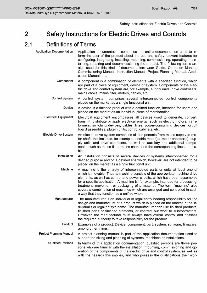
4.5 Data Sheet QSK075D-0200Designation Symbol Unit QSK075D-0200-NN-□□-UG□-NNNNContinuous torque at standstill 60 K M0_60 Nm 17.0Continuous current at standstill 60 K I0_60(rms) A 8.3Continuous torque at standstill 100K M0_100 Nm 18.5
Continuous current at standstill 100K I0_100(rms) A 9.0
Maximum torque Mmax Nm 64.0Maximum current Imax(rms) A 37.4Torque constant at 20 °C KM_N Nm/A 2.24Voltage constant at 20 °C1) KEMK_1000 V/min-1 138.0Winding resistance at 20 ℃ R12 Ohm 1.80Winding inductivity L12 mH 11.700Discharge capacity of the compo‐nent Cdis nF 4.6
Number of pole pairs o - 4Moment of inertia of the rotor Jrot kg*m2 0.00490Thermal time constant Tth min 22.0Maximum velocity nmax min-1 3,800Sound pressure level LP dB[A] 61.1 (±3)Mass mmot kg 20.1Surrounding air temperature duringoperation Tamb °C 0 ... 40
Degree of protection according toIEC 60529 IP - IP65
Insulation class according to DIN EN60034-1 I.CL. - 155
Data encoder M5 S5Encoder max. current consumption IEncoder mA 60
Encoder voltage supplyVCCEn‐
coderV 7...12
Encoder signal periods ~/⑀ - 128Encoder output signal Vout 1VssDistinguishable revolutions Uturn - 4,096 1Encoder Interface - - HiperfaceHolding brake data 0 1Holding torque M4 Nm - 23.00Input voltage (±10%) UN V - 24Rated current IN A - 0.79Connection time t1 ms - 130Disconnection time t2 ms - 180Holding brake moment of inertia Jbr kg*m2 - 0.0003000
Latest amendment: 2011-05-09
1) Manufacturing tolerance ±5 %
DOK-MOTOR*-QSK********-PR03-EN-P Rexroth IndraDyn S Synchronous Motors QSK061, -075, -100
Bosch Rexroth AG 31/87
Technical Data
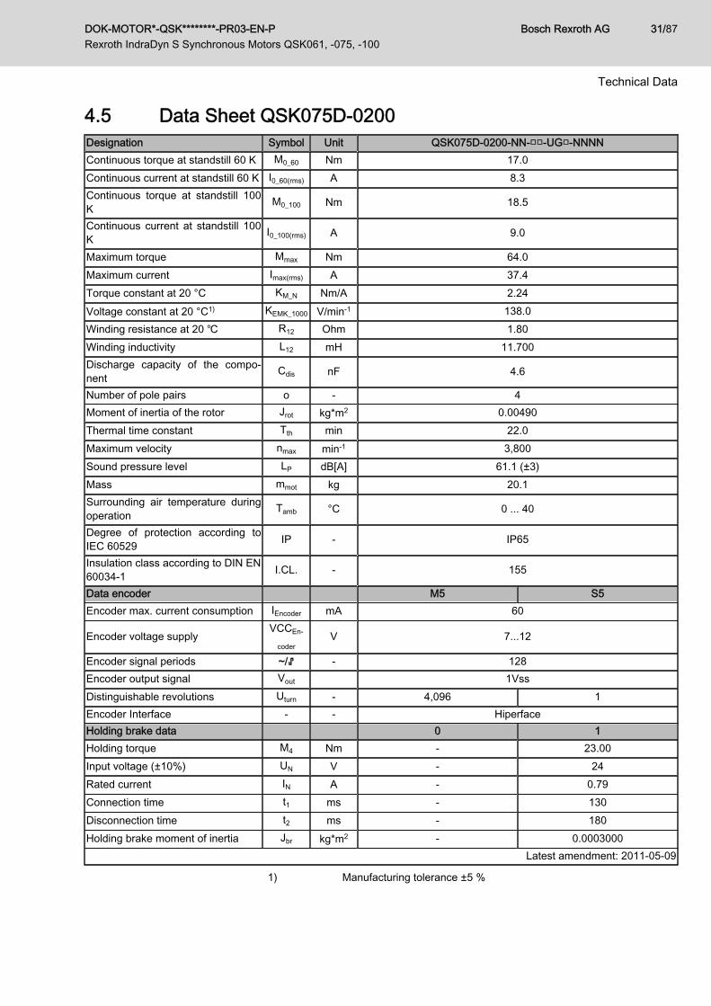
2) Mass motor withour holding brakeFig.4-11: QSK - technical data
QSK075D-0200
0
10
20
30
40
50
60
70
0 500 1000 1500 2000 2500 3000 3500 4000
n [min-1]
M [N
m]
3x AC 500 V 1)
Mmax HCQ02.1 X5.1/X5.2
S1
3x AC 400 V 1)
3x AC 200 V 1)
Mmax HCQ02.1 X5.3/X5.4
S3
S1 Characteristic continuous operation curveS3 Continuous operation curve; only in connection with HCQ02.1 X5.1/
X5.21) Power supply voltage -5 %Fig.4-12: Characteristic curve QSK075D-0200 on HCQ02.1
Bosch Rexroth AG DOK-MOTOR*-QSK********-PR03-EN-P Rexroth IndraDyn S Synchronous Motors QSK061, -075, -100
32/87
Technical Data

4.6 Data Sheet QSK075D-0300Designation Symbol Unit QSK075D-0300-NN-□□-UG□-NNNNContinuous torque at standstill 60 K M0_60 Nm 17.0Continuous current at standstill 60 K I0_60(rms) A 11.7Continuous torque at standstill 100K M0_100 Nm 18.5
Continuous current at standstill 100K I0_100(rms) A 12.7
Maximum torque Mmax Nm 66.0Maximum current Imax(rms) A 52.7Torque constant at 20 °C KM_N Nm/A 1.60Voltage constant at 20 °C1) KEMK_1000 V/min-1 98.2Winding resistance at 20 ℃ R12 Ohm 0.91Winding inductivity L12 mH 5.700Discharge capacity of the compo‐nent Cdis
Number of pole pairs o - 4Moment of inertia of the rotor Jrot kg*m2 0.00490Thermal time constant Tth min 22.0Maximum velocity nmax min-1 4,800Sound pressure level LP dB[A] 61.1 (±3)Weight 2) mmot kg 20.1Surrounding air temperature duringoperation Tamb °C 0 ... 40
Degree of protection according toIEC 60529 IP - IP65
Insulation class according to DIN EN60034-1 I.CL. - 155
Data encoder M5 S5Encoder max. current consumption IEncoder mA 60
Encoder voltage supplyVCCEn‐
coderV 7...12
Encoder signal periods ~/⑀ - 128Encoder output signal Vout 1VssDistinguishable revolutions Uturn - 4,096 1Encoder Interface - - HiperfaceHolding brake data 0 1Holding torque M4 Nm - 23.00Input voltage (±10%) UN V - 24Rated current IN A - 0.79Connection time t1 ms - 130Disconnection time t2 ms - 180Holding brake moment of inertia Jbr kg*m2 - 0.0003000
Latest amendment: 2011-05-11
1) Manufacturing tolerance ±5 %
DOK-MOTOR*-QSK********-PR03-EN-P Rexroth IndraDyn S Synchronous Motors QSK061, -075, -100
Bosch Rexroth AG 33/87
Technical Data
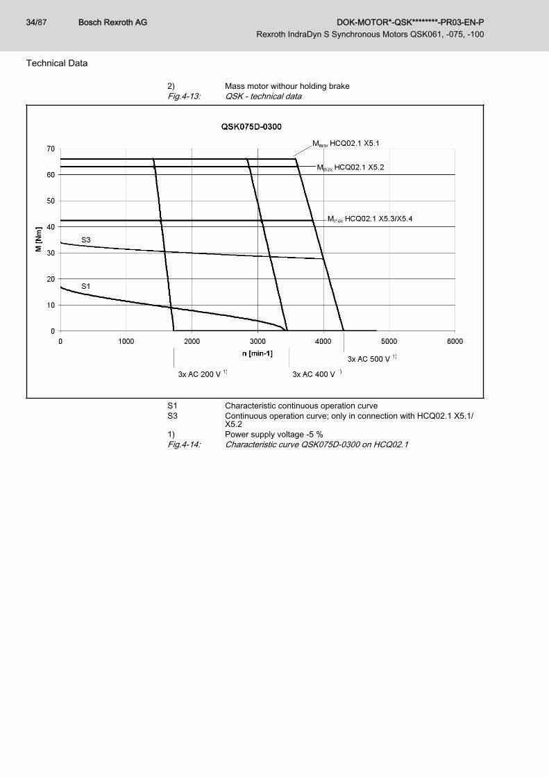
2) Mass motor withour holding brakeFig.4-13: QSK - technical data
S1 Characteristic continuous operation curveS3 Continuous operation curve; only in connection with HCQ02.1 X5.1/
X5.21) Power supply voltage -5 %Fig.4-14: Characteristic curve QSK075D-0300 on HCQ02.1
Bosch Rexroth AG DOK-MOTOR*-QSK********-PR03-EN-P Rexroth IndraDyn S Synchronous Motors QSK061, -075, -100
34/87
Technical Data

4.7 Data Sheet QSK075E-0200Designation Symbol Unit QSK075E-0200-NN-□□-UG□-NNNNContinuous torque at standstill 60 K M0_60 Nm 21.0Continuous current at standstill 60 K I0_60(rms) A 10.2Continuous torque at standstill 100K M0_100 Nm 23.0
Continuous current at standstill 100K I0_100(rms) A 11.2
Maximum torque Mmax Nm 88.0Maximum current Imax(rms) A 45.9Torque constant at 20 °C KM_N Nm/A 2.26Voltage constant at 20 °C1) KEMK_1000 V/min-1 139.0Winding resistance at 20 ℃ R12 Ohm 1.24Winding inductivity L12 mH 8.400Discharge capacity of the compo‐nent Cdis nF 5.8
Number of pole pairs o - 4Moment of inertia of the rotor Jrot kg*m2 0.00613Thermal time constant Tth min 29.0Maximum velocity nmax min-1 3,850Sound pressure level LP dB[A] 61.1 (±3)Weight 2) mmot kg 23.6Surrounding air temperature duringoperation Tamb °C 0 ... 40
Degree of protection according toIEC 60529 IP - IP65
Insulation class according to DIN EN60034-1 I.CL. - 155
Data encoder M5 S5Encoder max. current consumption IEncoder mA 60
Encoder voltage supplyVCCEn‐
coderV 7...12
Encoder signal periods ~/⑀ - 128Encoder output signal Vout 1VssDistinguishable revolutions Uturn - 4,096 1Encoder Interface - - HiperfaceHolding brake data 0 1Holding torque M4 Nm - 23.00Input voltage (±10%) UN V - 24Rated current IN A - 0.79Connection time t1 ms - 130Disconnection time t2 ms - 180Holding brake moment of inertia Jbr kg*m2 - 0.0003000
Latest amendment: 2011-05-11
1) Manufacturing tolerance ±5 %
DOK-MOTOR*-QSK********-PR03-EN-P Rexroth IndraDyn S Synchronous Motors QSK061, -075, -100
Bosch Rexroth AG 35/87
Technical Data

2) Mass motor withour holding brakeFig.4-15: QSK - technical data
QSK075E-0200
0
10
20
30
40
50
60
70
80
90
100
0 500 1000 1500 2000 2500 3000 3500 4000 4500
n [min-1]
M [N
m]
3x AC 500 V 1)
Mmax HCQ02.1 X5.1/X5.2
S1
3x AC 400 V 1)
3x AC 200 V 1)
Mmax HCQ02.1 X5.3/X5.4
S3
S1 Characteristic continuous operation curveS3 Continuous operation curve; only in connection with HCQ02.1 X5.1/
X5.21) Power supply voltage -5 %Fig.4-16: Characteristic curve QSK075E-0200 on HCQ02.1
Bosch Rexroth AG DOK-MOTOR*-QSK********-PR03-EN-P Rexroth IndraDyn S Synchronous Motors QSK061, -075, -100
36/87
Technical Data

4.8 Data Sheet QSK100B-0200Designation Symbol Unit QSK100B-0200-NN-□□-□G□-NNNNContinuous torque at standstill 60 K M0_60 Nm 28.0Continuous current at standstill 60 K I0_60(rms) A 14.7Continuous torque at standstill 100 K M0_100 Nm 33.0Continuous current at standstill 100 K I0_100(rms) A 17.3Maximum torque Mmax Nm 102.0Maximum current Imax(rms) A 66.2Torque constant at 20 °C KM_N Nm/A 2.10Voltage constant at 20 °C1) KEMK_1000 V/min-1 129.5Winding resistance at 20 ℃ R12 Ohm 0.58Winding inductivity L12 mH 7.6Discharge capacity of the component Cdis nF 10.3Number of pole pairs o - 4Moment of inertia of the rotor Jrot kg*m2 0.01920Thermal time constant Tth_nom min 40Maximum velocity nmax min-1 4,100Sound pressure level LP dB[A] 61.1 (±3)Weight 2) mmot kg 36.5Surrounding air temperature during operation Tamb °C 0 ... 40Protection class acc. to EN 60034 - - IP65Insulation class according to EN 60034-1 T.CL. - 155Data encoder M5Encoder max. current consumption IEncoder mA 60Encoder voltage supply VCCEncoder V 7...12Encoder signal periods ~/⑀ - 128Encoder output signal Vout 1VssDistinguishable revolutions Uturn - 4,096Encoder Interface - - HiperfaceHolding brake data 0 1Holding torque M4 Nm - 32.0Input voltage (±10%) UN V - 24Rated current IN A - 0.93Connection time t1 ms - 15Disconnection time t2 ms - 115Holding brake moment of inertia Jbr kg*m2 - 0.001242
Latest amendment: 2013-01-18
1) Manufacturing tolerance ±5 %2) Mass motor withour holding brakeFig.4-17: QSK - technical data
DOK-MOTOR*-QSK********-PR03-EN-P Rexroth IndraDyn S Synchronous Motors QSK061, -075, -100
Bosch Rexroth AG 37/87
Technical Data

S1 Characteristic continuous operation curveS3 Continuous operation curve; only in connection with HCQ02.1 X5.11) Power supply voltage -5 %Fig.4-18: Characteristic curve QSK100B-0200 on HCQ02.1
Bosch Rexroth AG DOK-MOTOR*-QSK********-PR03-EN-P Rexroth IndraDyn S Synchronous Motors QSK061, -075, -100
38/87
Technical Data

5 Dimensions
Fig.5-1: Dimensions QSK061
DOK-MOTOR*-QSK********-PR03-EN-P Rexroth IndraDyn S Synchronous Motors QSK061, -075, -100
Bosch Rexroth AG 39/87
Dimensions

Fig.5-2: Dimensions QSK075
Bosch Rexroth AG DOK-MOTOR*-QSK********-PR03-EN-P Rexroth IndraDyn S Synchronous Motors QSK061, -075, -100
40/87
Dimensions
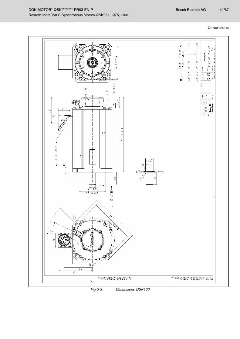
Fig.5-3: Dimensions QSK100
DOK-MOTOR*-QSK********-PR03-EN-P Rexroth IndraDyn S Synchronous Motors QSK061, -075, -100
Bosch Rexroth AG 41/87
Dimensions

Bosch Rexroth AG DOK-MOTOR*-QSK********-PR03-EN-P Rexroth IndraDyn S Synchronous Motors QSK061, -075, -100
42/87

6 Connection Technique6.1 Electric Connection Technique Overview
The electrical connections of IndraDyn S motors are standardized over allframe sizes. IndraDyn S motors are provided with● a power connector, incl. connection for temperature sensor and holding
brake,● an encoder connection.Both connectors are designed as plug-in connectors. When ready-made ca‐bles of Rexroth are used, a simple, fast and error-free assembly and commis‐sioning is ensured.
① Power connection with temperature sensor and holding brake② Encoder connectionFig.6-1: Overview of IndraDyn S connections IQSK connector
Motor Power connector Encoder connectorQSK061 RLS1100 RGS1000QSK075 RLS1200 RGS1000QSK100 RLS1300 RGS1003
Fig.6-2: Connector on QSK motorsThe maximum cable length for power and encoder cables between control‐lers HCQ02.1 or HCT02.1 and QSK motors is 40 m.Connection cable (power, ready-made)
Motor Order designationcable
Crosssection[mm²]
Converter
QSK061B-0300 RKL0020 1.0 HCT02.1, HCQ02.1QSK061C-0300 RKL0020 1.0 HCT02.1, HCQ02.1QSK075C-0300 RKL0022 1.5 HCT02.1, HCQ02.1QSK075D-0200QSK075D-0300
RKL0022 1.5 HCT02.1, HCQ02.1
DOK-MOTOR*-QSK********-PR03-EN-P Rexroth IndraDyn S Synchronous Motors QSK061, -075, -100
Bosch Rexroth AG 43/87
Connection Technique

Motor Order designationcable
Crosssection[mm²]
Converter
QSK075E-0200 RKL0022 1.5 HCT02.1, HCQ02.1QSK100B-0200 RKL0023 2.5 HCT02.1, HCQ02.1
Fig.6-3: Power cablesConnection cable (encoder, ready-made)
Motor Order designation ca‐ble Converter
QSK061 RKG4200 HCT02.1, HCQ02.1QSK075 RKG4200 HCT02.1, HCQ02.1QSK100 RKG4200 HCT02.1, HCQ02.1
Fig.6-4: Encoder Cables
Bosch Rexroth AG DOK-MOTOR*-QSK********-PR03-EN-P Rexroth IndraDyn S Synchronous Motors QSK061, -075, -100
44/87
Connection Technique

7 Operating Conditions and Application Notes7.1 Ambient Conditions7.1.1 Setup Elevation and Ambient Temperature
According to DIN EN 60034-1, the motor performance data specified beloware valid for:● Ambient temperatures 0 … 40 °C● Setup elevation 0 … 1,000 m above sea levelWhen exceeding the given limits, the performance data of the motors mustbe reduced.
① Utilization depending on the ambient temperature② Utilization depending on the installation altitudefT Temperature utilization factortA Ambient temperature in degrees CelsiusfH Height utilization factorh Installation altitude in metersFig.7-1: Derating of ambient temperature, installation altitude (in operation)Calculation of performance data in case the limits specified are exceeded:Ambient temperature > 40 °CM0_red = M0×fT Iinstallation altitude > 1,000 mM0_red = M0×fH Ambient temperature > 40 °C and setup elevation > 1,000 mM0_red = M0×fT×fH
DOK-MOTOR*-QSK********-PR03-EN-P Rexroth IndraDyn S Synchronous Motors QSK061, -075, -100
Bosch Rexroth AG 45/87
Operating Conditions and Application Notes

7.1.2 Humidity / Temperature Ambient climatic conditions are defined in different classes according to DINEN 60721-3-3, Table 1. They are based on observations made over long pe‐riods of time throughout the world and take into account all influencing quanti‐ties that could have an effect, such as the air temperature and humidity.Based on this table, Rexroth recommends class 3K4 for continuous use ofthe motors.The following table provides extracts from this class.
Environmental factor Unit Class 3K4
Low air temperature °C +5 1)High air temperature °C +40Low rel. air humidity % 5High rel. air humidity % 95Low absolute air humidity g/m³ 1High absolute air humidity g/m³ 29Temperature change rate °C/min 0.5
1) Rexroth permits 0 °C as the lowest air temperature.Fig.7-2: Classification of ambient climatic conditions according to
DIN EN 60721-3-3, Table 1
7.1.3 VibrationSinusoidal Vibrations Vibrations are sine-wave oscillations in stationary use, which vary in their ef‐
fect on the resistance of the motors depending on their intensity.The resistance of the overall system is determined by the weakest compo‐nent.Based on DIN EN 60721-3-3 and DIN EN 60068-2-6, the following values re‐sult for Rexroth motors:Maximum permissible vibration load (10-2,000 Hz)
Direction Encoder S5, M5Axial 10 m/s²Radial 30 m/s²
Latest amendment: 2009-03-20
Fig.7-3: Permissible vibration load for QSK motors
Bosch Rexroth AG DOK-MOTOR*-QSK********-PR03-EN-P Rexroth IndraDyn S Synchronous Motors QSK061, -075, -100
46/87
Operating Conditions and Application Notes

7.1.4 ShockThe shock load of the motors is indicated by providing the maximum permit‐ted acceleration in non-stationary use, such as during transport.Function-impairing effects are avoided as long as the limits specified arekept.Based on DIN EN 60721-3-3 and DIN EN 60068-2-6, the following values re‐sult for Rexroth motors:Maximum allowed shock load (6 ms)
Direction QSK061 QSK075 QSK100
Axial 10 m/s²
Radial 500 m/s² 300 m/s² 200 m/s²
Latest amendment: 2009-03-20
Fig.7-4: Permitted shock load for QSK motors
DOK-MOTOR*-QSK********-PR03-EN-P Rexroth IndraDyn S Synchronous Motors QSK061, -075, -100
Bosch Rexroth AG 47/87
Operating Conditions and Application Notes
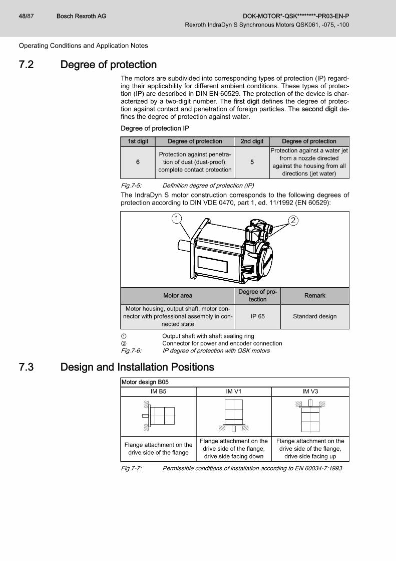
7.2 Degree of protectionThe motors are subdivided into corresponding types of protection (IP) regard‐ing their applicability for different ambient conditions. These types of protec‐tion (IP) are described in DIN EN 60529. The protection of the device is char‐acterized by a two-digit number. The first digit defines the degree of protec‐tion against contact and penetration of foreign particles. The second digit de‐fines the degree of protection against water.Degree of protection IP
1st digit Degree of protection 2nd digit Degree of protection
6Protection against penetra‐
tion of dust (dust-proof);complete contact protection
5
Protection against a water jetfrom a nozzle directed
against the housing from alldirections (jet water)
Fig.7-5: Definition degree of protection (IP)The IndraDyn S motor construction corresponds to the following degrees ofprotection according to DIN VDE 0470, part 1, ed. 11/1992 (EN 60529):
Motor area Degree of pro‐tection Remark
Motor housing, output shaft, motor con‐nector with professional assembly in con‐
nected stateIP 65 Standard design
① Output shaft with shaft sealing ring② Connector for power and encoder connectionFig.7-6: IP degree of protection with QSK motors
7.3 Design and Installation PositionsMotor design B05
IM B5 IM V1 IM V3
Flange attachment on thedrive side of the flange
Flange attachment on thedrive side of the flange,drive side facing down
Flange attachment on thedrive side of the flange,
drive side facing up
Fig.7-7: Permissible conditions of installation according to EN 60034-7:1993
Bosch Rexroth AG DOK-MOTOR*-QSK********-PR03-EN-P Rexroth IndraDyn S Synchronous Motors QSK061, -075, -100
48/87
Operating Conditions and Application Notes

Motor damage due to penetration of liquids!NOTICEIf motors are attached according to IM V3, fluid present at the output shaftover a prolonged time may penetrate and cause damage to the motors.Ensure that fluid cannot be present at the output shaft.
7.4 Compatibility with Foreign MaterialsAll Rexroth controls and drives are developed and tested according to thestate of the art.However, since it is impossible to follow the continuing further developmentof every material with which our controls and drives could come into contact(e.g. lubricants on tool machines), reactions with the materials that we usecannot be ruled out in every case.For this reason, you must execute a compatibility test between new lubri‐cants, cleansers, etc. and our housings and device materials before usingthese products.
7.5 Priming and Housing VarnishSpecification Housing Varnish
Color Black (RAL9005)Resistance Resistant against
● diluted acids/lyes● water, seawater, sewage● current mineral oilsResistant to a limited degree against● organic solvents● hydraulic oilNot resistant against● concentrated acids/lyes
Additional paint ● It is permitted to provide the housing with additional var‐nish (coat thickness no more than 40 µm). Before paintingthe housing, check the adhesiveness and resistance ofthe new paint.
Fig.7-8: Characteristics of the housing varnish
Protect all safety notes, type plates and open connectors with apainting protection when painting additionally.
7.6 Output Shaft7.6.1 Plain Shaft
The recommended standard model for IndraDyn S motors provides a non-positive, zero-backlash shaft-hub connection with a high degree of quiet run‐ning. Use clamping sets, pressure sleeves or clamping elements for couplingthe machine elements to be driven.
DOK-MOTOR*-QSK********-PR03-EN-P Rexroth IndraDyn S Synchronous Motors QSK061, -075, -100
Bosch Rexroth AG 49/87
Operating Conditions and Application Notes

7.6.2 Output Shaft with Shaft Sealing RingIndraDyn S motors are designed with radial shaft sealing rings according toDIN 3760 – design A.
① Radial shaft sealing ringFig.7-9: IndraDyn S radial shaft sealing ring
Wear Radial shaft sealing rings are friction seals. They are therefore subject towear and generate frictional heat.Wear of the friction seal can be reduced only if lubrication is adequate andthe sealing point is clean. Here, the lubricant also acts as a coolant, support‐ing the discharge of frictional heat from the sealing point.● Prevent the sealing point from becoming dry and dirty. Make sure every‐
thing is clean.
Under normal environmental conditions, the shaft seal is greasedfor its lifetime. Under unfavorable environmental conditions (e.g.grinding dust, metal shavings), however, maintenance intervalscould be necessary.
Resistance The materials used for radial shaft sealing rings are highly resistant againstoils and chemicals. However, the machine manufacturer is responsible tocheck whether the rings are suitable for the particular conditions of use.
The complex interactions between the sealing ring, the shaft and thesealing fluid, as well as the particular operating conditions (frictional heat,soiling, etc.), do not allow calculation of the lifetime of the shaft sealing ring.
Vertical Installation Positions IM V3
Motors with shaft sealing ring have IP 65 degree of protection on their flangeside. Hence, tightness is ensured only in case of splashing fluids. Fluid levelspresent on the A-side require a higher degree of protection. For vertical in‐stallation position (shaft at the top) of the motor, please observe the addition‐al notes in chapter 7.3 "Design and Installation Positions" on page 48 .
Rexroth recommends that any direct contact of the drive shaftand the radial shaft sealing ring with the processing medium(coolant, material corrosion) caused by the machine or systemconstruction be avoided.
Bosch Rexroth AG DOK-MOTOR*-QSK********-PR03-EN-P Rexroth IndraDyn S Synchronous Motors QSK061, -075, -100
50/87
Operating Conditions and Application Notes

7.7 Bearing and Shaft Load7.7.1 Radial Load, Axial Load
During operation, both radial and axial forces act upon the motor shaft andthe motor bearings. The construction of the machine, the selected motor typeand the attachment of driving elements on the shaft side must be adapted toeach other to ensure that the load limits specified are not exceeded.
Bearing Lifetime If motors are operated within the limits specified for radial and axial loads, thebearing lifetime is as follows:L10h = 20,000 operating hours(calculated according to ISO 281, ed. 12/1990)
X Force point of application of radial force Fradial, distance to the motorflange
Fradial Effective direction of radial forceFaxial Effective directions of axial forceFig.7-10: Axial and radial forceShaft load diagrams show the load limit for output shaft and motor bearing.
DOK-MOTOR*-QSK********-PR03-EN-P Rexroth IndraDyn S Synchronous Motors QSK061, -075, -100
Bosch Rexroth AG 51/87
Operating Conditions and Application Notes

① Maximum radial force Fradial characteristic curves "shaft breakage"② Maximum radial force Fradialcharacteristic curves "bearing load with
specified mean speed n"n Arithmetic average speedX Force point of application of radial force Fradial, distance to the motor
flangeFig.7-11: Example shaft load diagram
Permitted Radial Force The permitted radial force Fradial_max depends on the following factors:● Shaft-breaking load● Force point of application X● Arithmetically averaged speed (nmean)● Bearing lifetime (specified characteristic curves for L10h=20,000h)
Permitted Axial Force The maximum permitted axial force Faxial is proportional to the radial force.The maximum permitted axial force Faxial is indicated in the section on the ra‐dial force.
Mean Speed If the mean speed is calculated according to the following equation, the ac‐celeration and deceleration times are taken into account.
The initialization and braking times can be ignored in the calcula‐tion if the time in which the drive is operated at a constant speedis significantly greater than the acceleration and decelerationtimes.
A complete processing cycle can consist of several sections withdifferent speeds. In this case, the average must be calculatedfrom all sections.
Bosch Rexroth AG DOK-MOTOR*-QSK********-PR03-EN-P Rexroth IndraDyn S Synchronous Motors QSK061, -075, -100
52/87
Operating Conditions and Application Notes

n1m; n2m Mean speedn1; n2 Machining speedtH1; tH1 Acceleration timet1; t2 Machining timetB1; tB2 Deceleration timet11; t22 Standstill timeFig.7-12: Mean speed
DOK-MOTOR*-QSK********-PR03-EN-P Rexroth IndraDyn S Synchronous Motors QSK061, -075, -100
Bosch Rexroth AG 53/87
Operating Conditions and Application Notes
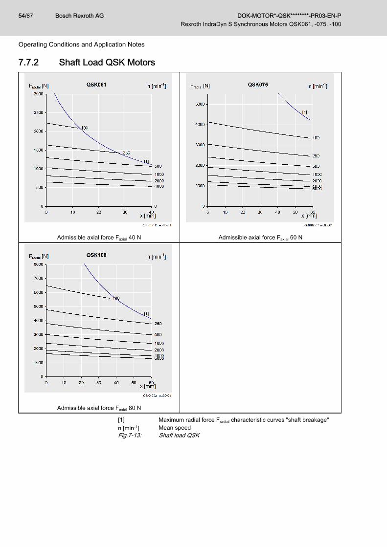
7.7.2 Shaft Load QSK Motors
Admissible axial force Faxial 40 N Admissible axial force Faxial 60 N
Admissible axial force Faxial 80 N
[1] Maximum radial force Fradial characteristic curves "shaft breakage"n [min-1] Mean speedFig.7-13: Shaft load QSK
Bosch Rexroth AG DOK-MOTOR*-QSK********-PR03-EN-P Rexroth IndraDyn S Synchronous Motors QSK061, -075, -100
54/87
Operating Conditions and Application Notes

7.8 Attachment of Drive Elements
Motor damage caused by penetration of flu‐ids!
CAUTION
If motors are attached according to IM V3, fluid present at the output shaftover a prolonged time may enter into and cause damage to the motors.⇒ Ensure that fluid cannot be present at the output shaft.
Whenever attaching drive elements to the output shaft, such as● Gearboxes● Couplings● Gear pinionit is absolutely necessary that the following guidelines be followed.
Gearbox Mounting on Motors Are gearboxes mounted on motors, the thermal coupling of the motors onmachines or constructions changes.Depending on the gearbox type, the heat development on the gearbox is dif‐ferent. The heat dissipation of the motor via the flange is reduced in everycase when a gearbox is mounted. This must be heeded at the project plan‐ning.A reduction of the given performance data is necessary, to do not overloadmotors when using gearboxes.
Fig.7-14: S1 characteristic curve of gearboxes
The indicated torques in the characteristic curves of the motorhave to be reduced by 20-30% when mounting gearboxes.
Please, heed all further notes and specifications within this documentation forthe used gearboxes.
Overdetermined Bearing Generally, overtermined bearings are to be avoided by all means when con‐necting drive elements. The tolerances inevitably present in such cases willlead to additional forces acting on the bearing of the motor shaft and, as thecase may be, to a distinctly reduced service life of the bearing.
If a redundant attachment cannot be avoided, it is absolutely nec‐essary to consult with Rexroth.
DOK-MOTOR*-QSK********-PR03-EN-P Rexroth IndraDyn S Synchronous Motors QSK061, -075, -100
Bosch Rexroth AG 55/87
Operating Conditions and Application Notes

Couplings The machine construction and the drive elements used must be carefullyadapted to the motor type so as to make sure that the load limits of the shaftand the bearing are not exceeded.
Motor damage due to mechanical overloadCAUTIONWhen extremely stiff couplings are attached, the radial force which constantlychanges the angular position may cause an impermissibly high load on theshaft and bearing.
Ball bearing pinion or helical drivepinion
Owing to thermal effects, the flange-sided end of the output shaft may shift by0.6 mm in relation to the motor housing. If helical drive pinions or bevel gearpinions directly attached to the output shaft are used, this change in positionwill lead to● a shift in the position of the axis, if the driving pinions are not defined
axially on the machine side,● a thermally dependent component of the axial force, if the driving pin‐
ions are defined axially on the machine side. This causes the risk of ex‐ceeding the maximum permissible axial force or of the play within thegears increasing to an impermissible degree.
● Damage of the motor bearing on the B-side due to exceeding of themaximum permissible axial force.
In such cases, drive elements should preferably be used withtheir own bearings which are connected to the motor drive shaftvia axially compensating couplings.
7.9 Holding Brakes 7.9.1 Holding Brake Electrically-Released
The holding brake of the IndraDyn S motors works according to the principle"electrically-released". Non-operative closed holding brakes open when ap‐plying the voltage.The voltage supply of the holding brake has to be designed so as to make avoltage of 24 V ±10% available on the motor for safe operation of the holdingbrake (releasing/applying).
The voltage incoming at the motor is subject to the line length andthe cable properties, e.g., conductor resistance.
Bosch Rexroth AG DOK-MOTOR*-QSK********-PR03-EN-P Rexroth IndraDyn S Synchronous Motors QSK061, -075, -100
56/87
Operating Conditions and Application Notes

t1 Connection timet2 Disconnection timeFig.7-15: Holding brake diagramThe electrically releasing holding brake is used to hold the axes at a standstilland when the ”controller enable” signal is off. When the supply voltage failsand the controller is enabled, the electrically-releasing holding brake willclose automatically.
Do not use the holding brake as an operating brake for movingaxes.
If the holding brake is repeatedly activated with the drive rotating or the al‐lowed braking energy is exceeded, premature wear and tear may occur.
7.9.2 Holding Brakes - Notes Regarding SafetyObserve the safety requirements for the system planning and development.
Personal injury through hazardous move‐ments caused by falling or descending axes!
DANGER
Secure vertical axes against falling or descending after disconnection:● lock the vertical axes mechanically,● provide an external braking / collecting / clamping device, or● Ensure sufficient weight compensation of the axes.The serially delivered holding brakes which are driven by the control deviceare not suited for personal safety!Personal protection must be realized by superordinate fail-safe measures,such as e.g. the locking off of the danger zone by means of a protectivefence or grill.
DOK-MOTOR*-QSK********-PR03-EN-P Rexroth IndraDyn S Synchronous Motors QSK061, -075, -100
Bosch Rexroth AG 57/87
Operating Conditions and Application Notes
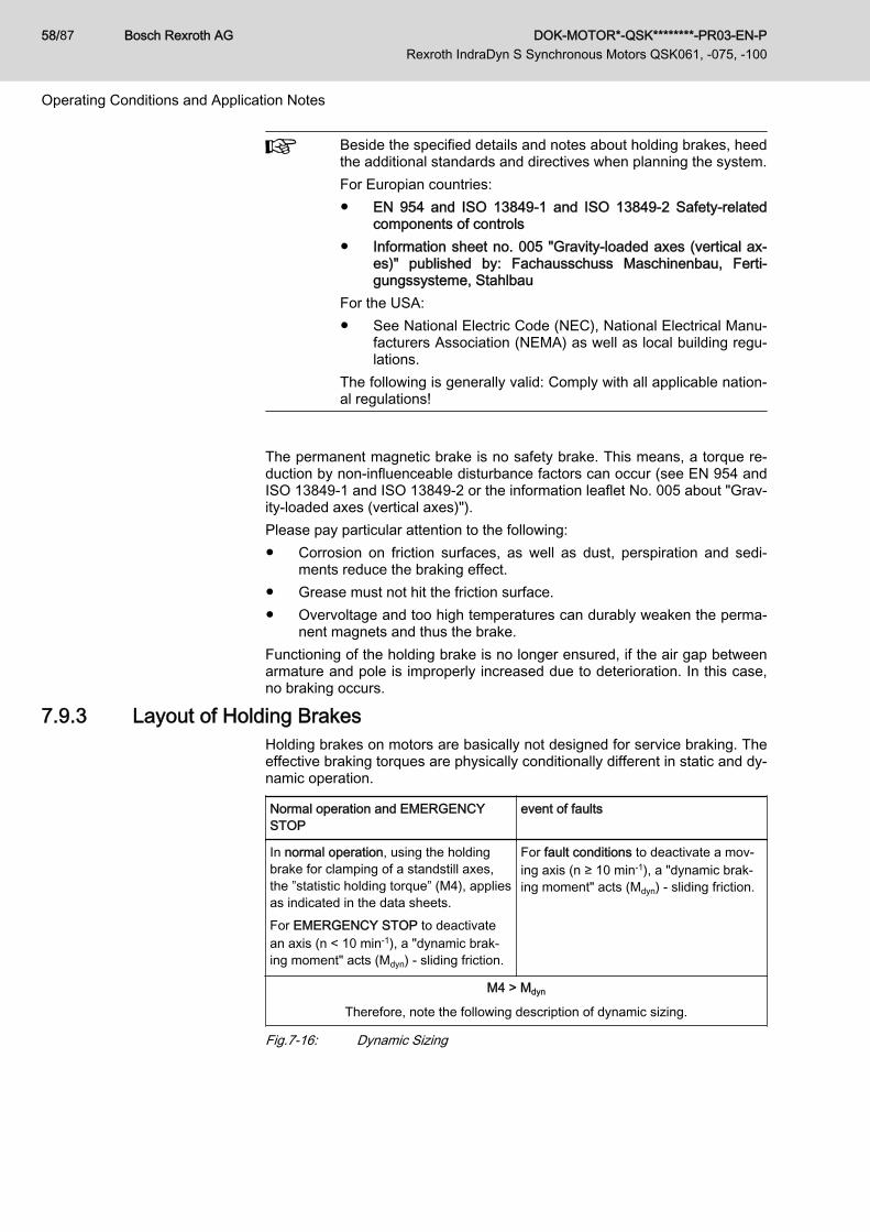
Beside the specified details and notes about holding brakes, heedthe additional standards and directives when planning the system.For Europian countries:● EN 954 and ISO 13849-1 and ISO 13849-2 Safety-related
components of controls● Information sheet no. 005 "Gravity-loaded axes (vertical ax‐
es)" published by: Fachausschuss Maschinenbau, Ferti‐gungssysteme, Stahlbau
For the USA:● See National Electric Code (NEC), National Electrical Manu‐
facturers Association (NEMA) as well as local building regu‐lations.
The following is generally valid: Comply with all applicable nation‐al regulations!
The permanent magnetic brake is no safety brake. This means, a torque re‐duction by non-influenceable disturbance factors can occur (see EN 954 andISO 13849-1 and ISO 13849-2 or the information leaflet No. 005 about "Grav‐ity-loaded axes (vertical axes)").Please pay particular attention to the following:● Corrosion on friction surfaces, as well as dust, perspiration and sedi‐
ments reduce the braking effect.● Grease must not hit the friction surface.● Overvoltage and too high temperatures can durably weaken the perma‐
nent magnets and thus the brake.Functioning of the holding brake is no longer ensured, if the air gap betweenarmature and pole is improperly increased due to deterioration. In this case,no braking occurs.
7.9.3 Layout of Holding BrakesHolding brakes on motors are basically not designed for service braking. Theeffective braking torques are physically conditionally different in static and dy‐namic operation.
Normal operation and EMERGENCYSTOP
event of faults
In normal operation, using the holdingbrake for clamping of a standstill axes,the ”statistic holding torque” (M4), appliesas indicated in the data sheets.For EMERGENCY STOP to deactivatean axis (n < 10 min-1), a "dynamic brak‐ing moment" acts (Mdyn) - sliding friction.
For fault conditions to deactivate a mov‐ing axis (n ≥ 10 min-1), a "dynamic brak‐ing moment" acts (Mdyn) - sliding friction.
M4 > Mdyn
Therefore, note the following description of dynamic sizing.
Fig.7-16: Dynamic Sizing
Bosch Rexroth AG DOK-MOTOR*-QSK********-PR03-EN-P Rexroth IndraDyn S Synchronous Motors QSK061, -075, -100
58/87
Operating Conditions and Application Notes

Dynamic Sizing The load torque must be smaller than the minimum dynamic moment Mdynwhich the holding brake can provide. Otherwise the dynamic holding braketorque is not sufficient to stop the axes.If a mass is to be decelerated in a defined time or in a defined route, the addi‐tional mass moment of inertia of the whole system must be taken into ac‐count.
Project planning recommendation To ensure construction safety, reduce the required holding torque to 60% ofthe static holding torque (M4) of the holding brake.
7.9.4 Holding Brake–Commissioning and Maintenance Instructions In order to ensure proper functioning of the holding brake, it must be checkedbefore the motors are commissioned. The test as well as the resurfacing maybe carried out "mechanically by hand" or "automatically by means of the soft‐ware function".
Checking and resurfacing of hold‐ing brakes by hand
Measure the holding torque (M4) of the holding brake. If necessary, resurfacethe holding brake.
Measuring the Holding Torque (M4) of the Holding Brake1. De-energize the motor and secure it against re-energization.2. Measure the transferable holding torque of the holding brake with a tor‐
que wrench. For holding torque (M4) refer to the technical data.If the holding torque (M4) is achieved, the motor is ready for assembly.If the holding torque (M4) is not achieved, the subsequent resurfacing-process can be used to reconstitute the holding torque.
Resurfacing the Holding Brake1. At closed holding brake, turn the output shaft by hand, e.g. with the help
of a torque wrench, by about 5 revolutions.2. Measure the holding torque (M4).
If the holding torque (M4) is achieved, the motor is ready for assembly.If the specified holding torque (M4) is not attained after several grinding-in processes, the holding brake is not operable. Please, contact theRexroth Service.
Checking and resurfacing of hold‐ing brakes by means of the soft‐
ware function
Checking the Holding Torque (M4) via P-0-0541, C2100 CommandHolding system check1. The efficiency of the holding brake and the opened state are checked by
the control device by starting the routine "P-0-0541, C2100 CommandHolding system check".If the holding brake is operational, the drive is in an operational state af‐ter the routine was run through. If the braking torque is too low, the con‐trol device outputs a corresponding message.
The brake test can also be carried out cyclically in the frameworkof a preventive maintenance.
Restoring the Holding Torque (M4) by means of the Software FunctionThe following possibilities are available:
DOK-MOTOR*-QSK********-PR03-EN-P Rexroth IndraDyn S Synchronous Motors QSK061, -075, -100
Bosch Rexroth AG 59/87
Operating Conditions and Application Notes
1. Realization of the resurfacing routine IndraDrive "Restoring the holdingtorque "(see"P-0-0544, C3900 Command Resurfacing of motor holdingbrake"). A repeated realization of the resurfacing routine is possible.Upon the execution of the command C3900 it is not checked whetherthe resurfacing of the holding brake was successful. It is recommendedto execute the command C2100 (Command Holding system check)once again.
2. Resurfacing routine by superior control. Here, special control programsadapted to the machine and system concepts are required. If necessary,please contact your Bosch Rexroth distribution partner and discuss theresurfacing routine parameters for your application.
For more detailed information about software functions refer to the func‐tional description "Rexroth IndraDrive Firmware for Drive Control DevicesMPx-xx, DOK-INDRV*-MP*-xxVRS**-FKxx-EN-P."
7.10 Motor CoolingRexroth motors of the standard design are self-cooling motors.
Pollution of the motors reduces the heat dissipation. Ensure tidi‐ness!
7.11 Motor Temperature Monitoring7.11.1 General Information
The motor temperature is monitored by two systems that are operated inde‐pendently of each other● Temperature sensor● Temperature modeland ensures thus the best protection of motors against irreversible damageby thermal overload.
7.11.2 Temperature SensorThe monitoring of the motor temperature is ensured via the temperature sen‐sor of the KTY84 type, which is built into the stator. The motor temperaturemeasured is controlled via the following threshold values:● Motor - warning temperature (140 °C)● Motor - switch-off temperature (150 °C)The threshold values are filed within the encoder memory of the QSK motors.
Bosch Rexroth AG DOK-MOTOR*-QSK********-PR03-EN-P Rexroth IndraDyn S Synchronous Motors QSK061, -075, -100
60/87
Operating Conditions and Application Notes

Fig.7-17: Characteristic curve KTY84-130The IndraDrive control devices monitor the functionality of the temperaturesensors.For further information, please refer to the functional description of IndraDrivecontrol devices.
DOK-MOTOR*-QSK********-PR03-EN-P Rexroth IndraDyn S Synchronous Motors QSK061, -075, -100
Bosch Rexroth AG 61/87
Operating Conditions and Application Notes

7.12 Acceptances and Approvals7.12.1 CE Symbol
Declaration of Conformity The certificates of conformity certifying the structure of and the compliancewith the valid EN standards and EC guidelines are available for all IndraDynS. If necessary, these declarations of conformity can be requested from theresponsible sales office.The CE mark is applied to the motor type label of the IndraDyn S.
Fig.7-18: CE mark
Bosch Rexroth AG DOK-MOTOR*-QSK********-PR03-EN-P Rexroth IndraDyn S Synchronous Motors QSK061, -075, -100
62/87
Operating Conditions and Application Notes

8 Transport and Storage8.1 Transport Instructions
Transport our products only in their original package. Also observe specificambient factors to protect the products from transport damage.Based on EN 60721-3-2, the tables below specify classifications and limitvalues which are allowed for our products while they are transported by land,sea or air. Observe the detailed description of the classifications to take all ofthe factors which are specified in the particular class into account.Allowed classes of ambient conditions during transport acc. to EN 60721-3-2
Classification type Allowed class
Classification of climatic ambient conditions 2K2
Classification of biological ambient conditions 2B1
Classification of chemically active materials 2C2
Classification of mechanically active materials 2S2
Classification of mechanical ambient conditions 2M1
Fig.8-1: Allowed classes of ambient conditions during transportFor the sake of clarity, a few essential environmental factors of theaforementioned classifications are presented below. Unless otherwisespecified, the values given are the values of the particular class. However,Bosch Rexroth reserves the right to adjust these values at any time based onfuture experiences or changed ambient factors.Allowed transport conditions
Environmental factor Symbol Unit Value
Temperature TT °C -20 ... +801)
Air humidity(relative air humidity, not combinablewith quick temperature change)
φ % 75 (at +30 °C)
Occurence of salt mist Not permitted 1)
1) Differs from EN 60721-3-2Fig.8-2: Allowed transport conditions
Before transport, empty the liquid coolant from the liquid-cooledmotors to avoid frost damage.
Transport by air If motor components with permanent magnets are shipped by air, theDGR (Dangerous Goods Regulations) of the IATA (International Air TransportAssociation) for hazardous materials of class 9 which also includemagnetized substances and objects must be observed. For example, theseregulations are applicable for● Secondary parts of synchronous linear motors● Rotors of synchronous kit motors● Rotors of synchronous housing motors (if shipped as motor
components, i.e., separated from the stator or motor housing in caseservice work is required)
DOK-MOTOR*-QSK********-PR03-EN-P Rexroth IndraDyn S Synchronous Motors QSK061, -075, -100
Bosch Rexroth AG 63/87
Transport and Storage

For information on the maximum allowed magnetic strenghts and methods ofmeasuring such magnetic field strengths, please refer to the current IATADGR (chapter 3.9.2.2).
Bosch Rexroth AG DOK-MOTOR*-QSK********-PR03-EN-P Rexroth IndraDyn S Synchronous Motors QSK061, -075, -100
64/87
Transport and Storage

8.2 Storage Instructions8.2.1 Storage Conditions
Generally, Bosch Rexroth recommends to store all components until they areactually installed in the machine as follows:● In their original package● At a dry and dustfree location● At room temperature● Free from vibrations● Protected against light or direct insolationOn delivery, protective sleeves and covers may be attached to our motors.They must remain on the motor for transport and storage. Do not removethese parts until shortly before assembly.Based on EN 60721-3-1, the tables below specify classifications and limitvalues which are allowed for our products while they are stored. Observe thedetailed description of the classifications to take all of the factors which arespecified in the particular classification into account.Allowed classes of ambient conditions during storage acc. to EN 60721-3-1
Classification type Class
Classification of climatic ambient conditions 1K2
Classification of biological ambient conditions 1B1
Classification of chemically active materials 1C2
Classification of mechanically active materials 1S1
Classification of mechanical ambient conditions 1M2
Fig.8-3: Allowed classes of ambient conditions during storageFor the sake of clarity, a few essential environmental factors of theaforementioned classifications are presented below. Unless otherwisespecified, the values given are the values of the particular class. However,Bosch Rexroth reserves the right to adjust these values at any time based onfuture experiences or changed ambient factors.Allowed classes of ambient conditions during storage acc. to EN 60721-3-1
Environmental factor Symbol Unit Value
Air temperature TL °C -20 ... +601)
Relative air humidity φ % 5 … 95
Absolute air humidity ρw g/m³ 1 … 29
Condensation - - - - Not allowed
Ice formation/freezing - - - - Not allowed
Direct solar radiation - - - - Not allowed 1)
Occurence of salt mist - - - - Not allowed 1)
1) Differs from EN 60721-3-1Fig.8-4: Allowed storage conditions
DOK-MOTOR*-QSK********-PR03-EN-P Rexroth IndraDyn S Synchronous Motors QSK061, -075, -100
Bosch Rexroth AG 65/87
Transport and Storage

Before re-storage, empty the liquid coolant from the liquid-cooledmotors to avoid frost damage.
8.2.2 Storage TimesAdditional measures must be taken on commissioning to preserve properfunctioning – irrespective of the storage time which may be longer than thewarranty period of our products. However, this does not involve anyadditional warranty claims.Motors
Bearing time / monthsMeasures for commissioning
> 1 > 12 > 60
■ ■ ■ Visual inspection of all parts to be damage-free
■ ■ ■ Resurface the holding brake
■ ■ Check the electric contacts to verify that they are free fromcorrosion
■ ■ Let the motor run in without load for one hour at 800 ...1000 rpm
■ ■ Measure insulation resistance. Dry the winding at a valueof < 1kOhm per volt rated voltage.
■ Exchange bearings
■ Exchange encoders
Fig.8-5: Measures before commissioning motors that have been stored over aprolonged period of time
Cables and Connectors
Bearing time / monthsMeasures for commissioning
> 1 > 12 > 60
■ ■ ■ Visual inspection of all parts to be damage-free
■ ■ Check the electric contacts to verify that they are free fromcorrosion
■Visually inspect the cable jacket. Do not use the cable ifyou detect any abnormalities (squeezed or kinked spots,color deviations, ...).
Fig.8-6: Measure before commissioning cables and connectors that have beenstored over a prolonged period of time
Bosch Rexroth AG DOK-MOTOR*-QSK********-PR03-EN-P Rexroth IndraDyn S Synchronous Motors QSK061, -075, -100
66/87
Transport and Storage

9 Delivery Status, Identification, Handling9.1 State of Delivery9.1.1 General Information
On delivery, the QSK motors are packed in cardboard boxes or woodencrates. Packing units on pallets are secured by means of retaining straps.
Injuries due to uncontrolled movement of theretaining straps when cutting!
CAUTION
Maintain a sufficient distance and carefully cut the bandages.
Upon delivery from the factory, the motor drive shaft and the connectors haveprotective sleeves. Remove the protective sleeves just before assembly.
9.1.2 Inspection at the FactoryAll QSK motors undergo the following tests, among others, at the factory:
Electrical test ● High voltage test● Isolation resistance test● Protective conductor connection● Test of winding resistance
Mechanical test ● Concentricity and position tolerances of shaft end and fastening flange● Axial eccentricity of the flange face to the shaft● Coaxiality of the centering shoulder to the shaft● Test of brake holding torque (option)
9.1.3 Test Realized by the CustomerSince all QSK motors undergo a standardized inspection procedure, high-voltage tests on the customer side are not required. Motors and componentscould be damaged if they undergo several high-voltage inspections.
Destruction of motor components due to im‐properly executed high-voltage inspection! In‐validation of warranty!
NOTICE
Avoid repeated inspections.Please observe the target values of the EN 60034-1.
DOK-MOTOR*-QSK********-PR03-EN-P Rexroth IndraDyn S Synchronous Motors QSK061, -075, -100
Bosch Rexroth AG 67/87
Delivery Status, Identification, Handling

9.2 Identification9.2.1 Scope of Delivery
The total scope of a delivery can be seen in the delivery note or waybill. How‐ever, the contents of a delivery can be distributed over several packages.Each individual package can be identified using the shipment label attached.Please, check after receiving the delivery, if the delivered goods comply withyour order and the shipping documents.Complain any deviation at your responsible Rexroth sales partner, immedi‐ately.Complain any visible transport damage directly at the deliverer.
9.2.2 Type PlateEach motor has an individual type plate showing the device designation andproviding technical information. Additionally, a second type plate is deliveredwith the motor.If the original type plate of the motor is obscured by the machine construc‐tion, use the second type plate to an easily visible portion of the machine.This type plate is either enclosed to the motor or is removably glued onto theoriginal type plate.The type plate is provided for● Identification of the motor● Procurement of spare parts in case of a fault● Service information.
The type designation of the motor is also filed in the encoder datamemory.
Motor name plate
Fig.9-1: Type label (example: IndraDyn S)
Bosch Rexroth AG DOK-MOTOR*-QSK********-PR03-EN-P Rexroth IndraDyn S Synchronous Motors QSK061, -075, -100
68/87
Delivery Status, Identification, Handling

9.3 Handling
Injuries due to improper handling duringtransport of motors!
CAUTION
Do only use suitable lifting devices (e.g. lifting sling belts, eyebolts, chain sus‐pension ...).Use protective equipment and personal protective clothing (gloves, safetyshoes, ...).Never walk under hanging loads.
Damage of property and invalidation of thewarranty due to incorrect storage!
NOTICE
Store the motors horizontally in their original packaging in a dust-free, dry, vi‐bration-free and sun-protected environment.
Also observe the notes regarding storage and transport on the packaging.Handling On delivery, the QSK motors have protective caps and covers on the output
shaft and on the flange sockets. During transport and storage, the protectivesleeves must remain on the motor.● Remove the protective sleeves just before assembly.● Also use the protective sleeves if you return the goods.● Avoid any damage to the motor flange and drive shaft.
① Power connector protective sleeve② Encoder connector protective sleeve③ Shaft protective sleeveFig.9-2: IndraDyn S protective sleeves
Motor damage due to beats onto the motorshaft
NOTICE
Do never beat onto the shaft end and do not exceed the allowed axial andradial forces of the motor.
Transport Please, observe the following points during transport:
DOK-MOTOR*-QSK********-PR03-EN-P Rexroth IndraDyn S Synchronous Motors QSK061, -075, -100
Bosch Rexroth AG 69/87
Delivery Status, Identification, Handling

● Use suitable means of transport and consider the weight of the compo‐nents (you can find the weight information on the data sheets or on thetype plate of the motor).
● Provide appropriate shock absorbers, if strong vibrations may occur dur‐ing transport.
● Transport the motors only in the horizontal position.● Use cranes with lifting sling belts to lift the motors.
Fig.9-3: Lifting and transporting motors by means of lifting sling belts
Bosch Rexroth AG DOK-MOTOR*-QSK********-PR03-EN-P Rexroth IndraDyn S Synchronous Motors QSK061, -075, -100
70/87
Delivery Status, Identification, Handling

10 Installation10.1 Safety
Injuries caused by live parts! Lifting of heavyloads!
WARNING
● Install the motors only when they are de-energized and not connectedelectrically.
● Use suitable tackles, protective equipment and protective clothing dur‐ing transport.Observe the notes regarding safety given in previous chapters.
Carry out all working steps with particular care This minimizes the risk of ac‐cidents and damage.
10.2 Skilled PersonnelAny works on the system and on the drives or in their vicinity must only becarried out by appropriately trained technical personnel.Please make sure that all persons carrying out● installation works● maintenance, or● operating activitieson the system are adequately familiar with the contents of this documentationas well as with all warnings and precautionary measures contained therein.
Qualified technical personnel are those persons who have been trained,instructed or are authorized to activate and deactivate, ground and markelectric circuits and equipment according to the technical safety regulations.Qualified technical personnel must possess appropriate safety equipmentand have been trained in first aid.
10.3 Mechanical Attachment10.3.1 Flange Assembly
To attach the motors properly and safely to the machine, Bosch Rexroth rec‐ommends the following screws and washers for attachment.
The screwed connections must be able to take up both the forcedue to the weight of the motor and the forces acting during opera‐tion.
Normally, use pan head screw DIN 912 - M... x ... -8.8 and appropriate wash‐ers acc. to DIN EN 28738. For some motors, it is not necessary to enclosewashers, see table.
If the screws and washers used do not comply with this recom‐mendation, the property class of the screws and the hardnessclass must be equivalent in order to transmit the required tighten‐ing torques.
DOK-MOTOR*-QSK********-PR03-EN-P Rexroth IndraDyn S Synchronous Motors QSK061, -075, -100
Bosch Rexroth AG 71/87
Installation

IndraDyn S motors are designed for flange assembly (B05). Details on themounting holes are given in the corresponding dimension sheet. In general,the following assignment is applicable for attaching the motors:Recommended screws for flange fastening of the QSK motors
B05 (flange assembly)
Hole Screw (8.8)Wash‐
er DIN EN 28738
Ø [mm] Type 1) MGA [Nm] Ø [mm]
QSK061 9.0 M8×20 25 10
QSK075 11.0 M10×30 51 12
QSK100 14.0 M12×40 87 14
① Mounting holeMGA Tightening torque in Newton meters1) Minimum screw length for screwing into steel.Fig.10-1: QSK mounting accessories (flange assembly)
10.3.2 Preparing Assembly● Record all measures taken in the commissioning log.Prepare motor assembly as follows:
1. Check the components for visible damage. Damaged components maynot be mounted.
2. Ensure that the dimensions and tolerances of the plant are suitable formotor attachment (for details, see dimension drawing).
3. Ensure that the motor can be assembled in a clean, dry and dustfreeenvironment.
4. Keep tools and auxiliary materials as well as measuring and testingequipment ready at hand.
5. Inspect all components, mounting surfaces and threads to ensure theyare clean.
6. Ensure that the machine-sided receptacle for the motor flange has noburrs.
7. Remove the protective sleeve from the motor shaft. Keep the sleeve forlater use.
8. Check the motors with holding brake, whether the holding brake rea‐ches the holding torque indicated on the data sheet. If the holding brakedoes not reach the indicated holding torque, proceed as follows. (Alsorefer to chapter 7.9.4 "Holding Brake–Commissioning and MaintenanceInstructions " on page 59chapter 7.9.4 Holding Brake Commissioningand Maintenance Instructions.)
10.3.3 Assembling the Motor● Mount the motor.Please note:● Avoid clamping or jamming the motor-sided centering collar.● Avoid damaging the plant-sides receptacle fit.● Connect the motor to the machine (observe tightening torques).
Bosch Rexroth AG DOK-MOTOR*-QSK********-PR03-EN-P Rexroth IndraDyn S Synchronous Motors QSK061, -075, -100
72/87
Installation

● Check whether the connection is firm and accurate before carrying outany further steps.
After having assembled the motor mechanically, prepare it for electrical con‐nection.
10.4 Electrical Connection – Motor Assembly10.4.1 General Information
It is recommended that you use ready-made Rexroth connection cables.These cables provide a number of advantages, such as UL/CSA authoriza‐tion, extreme load capability and resistance as well as a design suitable forEMC.
Danger! Electric voltage! Handling within thearea of live parts is extremely dangerous.
DANGER
● Work required on the electric system may only be carried out by skilledelectricians. It is absolutely necessary to use power tools.
● Before the work can be started, the system must be de-energized andthe power switch be secured against unintentional or unauthorized re-starting.
● Before the work can be started, an appropriate measuring device mustbe used to check whether parts of the system are still under residualvoltage (e.g. caused by capacitors, etc.). If yes, wait until these partshave discharged.
Injuries to persons or damage to propertypossible! Interrupting or connecting live linesmay cause unpredictable dangerous situa‐tions or lead to damage to property.
WARNING
● Connect and disconnect connectors only when they are dry and de-energized.
● During operation of the system, all connectors must be securely tight‐ened.
Risk of short-circuit caused by liquid coolantor lubricant! Short-circuits of live lines maycause unpredictable dangerous situations orlead to damage to property.
WARNING
● Provide open sides of the power connectors with protective caps, wheninstalling or replacing drive components.
10.4.2 Attaching the ConnectorsPower/Encoder Connectors When fitting the encoder connector with a screwed end fitting, proceed as fol‐
lows:1. Place the power connector in the correct position onto the thread of the
connection housing.2. Tighten the union nut of the power connector manually. By leading the
cable in further, the power connector can be steadily brought to its finalposition.
DOK-MOTOR*-QSK********-PR03-EN-P Rexroth IndraDyn S Synchronous Motors QSK061, -075, -100
Bosch Rexroth AG 73/87
Installation

3. Completely tighten the union nut.
Only completely tightened union nuts guarantee the indicatedIP65 protection against water and activate the vibration protec‐tion.
10.4.3 Adjusting the Output DirectionRLS1100, RLS1200 and
RGS1000The flange sockets can be turned through 240°.The motor flange socket can be turned if an appropriate connector has beenattached. Owing to the leverage of the attached connector, the flange socketcan be turned manually to the desired position.1. Connect the motor power cable to the flange socket.2. Move the flange socket to the desired output direction by turning the
plugged-in connector.
Do not use any tools (e.g. pliers or screwdrivers) to turn the motorflange socket. Mechanical damage to the flange socket when us‐ing tools cannot be excluded.
The desired output direction is set.
Whenever the flange socket is turned, the holding torque in theset position is reduced. To ensure the required holding torque ofthe flange socket, the output direction should be changed nomore than 5 times!
RLS1300 The output direction of the RLS1300 is not adjustable!
Bosch Rexroth AG DOK-MOTOR*-QSK********-PR03-EN-P Rexroth IndraDyn S Synchronous Motors QSK061, -075, -100
74/87
Installation

11 Commissioning, Operation and Maintenance11.1 Commissioning
Damage to life or property due to errors in thecontrols of motors and moving elements! Un‐clear operating states and product data!
CAUTION
● Do not carry out commissioning if connections, operating states or prod‐uct data are unclear or faulty.
● Do not carry out commissioning if the safety and monitoring equipmentof the system is damaged or not in operation.
● Damaged products must not be put into operation!● Contact Rexroth for missing information or support during commission‐
ing.
The following commission notes refer to the motors as part of a drive-systemwith drive and control unit.Preparation
1. Keep the documentation of all products you are using ready.2. Check the products for damage.3. Check all mechanical and electrical connections.4. Activate the safety and monitoring equipment of the system.5. Make sure that the optional holding brakes are ready for operation. (de‐
scribed in chapter 7.9.4 Holding Brake - Commissioning and Mainte‐nance Instructions on page 55.).
Bulk head connectorWhen all requirements are met, proceed as follows:
1. Carry out the commissioning of the drive system according to the in‐structions provided in the respective documentation. You can find therespective information in the functional description of the drive controldevices.
Commissioning of drive controllers and the control unit may requireadditional steps. The inspection of the functioning and performance ofthe systems is not part of the commissioning of the motor; instead, it iscarried out within the framework of the commissioning of the machine asa whole. Observe the instructions and regulations given by the machinemanufacturer.
11.2 OperationKeep the described ambient conditions during operation (cf. chapter 11 "Commissioning, Operation and Maintenance " on page 75).
11.3 DeactivationIn the case of malfunctions or maintenance, or to deactivate the motors, pro‐ceed as follows:
1. Observe the instructions of the machine documentation.
DOK-MOTOR*-QSK********-PR03-EN-P Rexroth IndraDyn S Synchronous Motors QSK061, -075, -100
Bosch Rexroth AG 75/87
Commissioning, Operation and Maintenance

2. Use the machine-side control commands to bring the drive to a control‐led standstill.
3. Switch off the power and control voltage of the drive controller.4. Switch off the main switch of the machine.5. Secure the machine against accidental movements and against unau‐
thorized operation.6. Wait for the discharge time of the electrical systems to expire and then
disconnect all electrical connections.7. Before dismantling, secure the motor against falling or movements be‐
fore disconnecting the mechanical connections.
11.4 Maintenance11.4.1 General Information
Synchronous motors operate maintenance free within the specified operatingconditions and lifetime. However, operation under unfavorable conditions canlead to limitations in availability.● Increase availability with regular preventive maintenance measures. Ob‐
serve the information in the maintenance schedule of the machine man‐ufacturer and the service measures described below.
Burns may be caused through hot surfaceswith temperatures over 100 °C
WARNING
● Do not work on hot surfaces.● Use safety gloves.⇒ Let the motor cool down before maintenance. The thermal time constantstated in the technical data is a measure for the cooling time. A cooling timeup to 140 minutes can be necessary!
Danger of injury due to moving elements!WARNING● Do not carry out any maintenance measures, while the machine is run‐
ning.● During maintenance work, secure the system against restarting and un‐
authorized use.
11.4.2 CleaningDirt, dust or chips may adversely affect the functionality of the motors and, inextreme cases, even cause a failure of the motors. Clean the cooling fins ofthe motors at regular intervals (after one year at the latest) to reach a suffi‐ciently high heat emission surface. If the motors are dirty, sufficient heat dis‐sipation via the environmental air is not possible any longer.An insufficient heat radiation may have undesired consequences.● The lifetime is reduced● Overtemperature deactivation
Bosch Rexroth AG DOK-MOTOR*-QSK********-PR03-EN-P Rexroth IndraDyn S Synchronous Motors QSK061, -075, -100
76/87
Commissioning, Operation and Maintenance

11.4.3 BearingsThe nominal lifetime of the bearings is L10h = 20000 h according toDIN ISO 281, ed. 1990, provided the permissible radial and axial forces arenot exceeded.The motor bearings should be replaced if● the nominal bearing service life has been reached,● running noises occur.
We recommend that bearings be replaced by the Rexroth Serv‐ice.
11.4.4 Connecting Cables
Death by electrocution possible due to liveparts!
DANGER
If the slightest defect is detected in the cable sheath, the system must beshut down immediately. Then the cable must be replaced. Do not repair any connection lines provisionally.
● Check connection cables for damage at regular intervals and replacethem, if necessary.
● Check any optional energy management chains (drag chains) for de‐fects.
● Check the protective conductor connection for proper state and tightseat at regular intervals and replace it, if necessary.
DOK-MOTOR*-QSK********-PR03-EN-P Rexroth IndraDyn S Synchronous Motors QSK061, -075, -100
Bosch Rexroth AG 77/87
Commissioning, Operation and Maintenance

11.5 Notice of Malfunctions
Electrocution by live parts of more than 50 V!WARNINGBefore working on live parts: De-energize the machine and secure the mainsswitch again unintendet or unauthorized re-energization.Check if the voltage is dropped down under 50 V before touching live parts!
Combustions via hot surface with tempera‐tures over 100 °C
WARNING
Let the motor cool down, before maintenance. The thermal time constant sta‐ted in the technical data is a measure for the cooling time. A cooling time upto 140 minutes can be necessary!Do not work on hot surfaces.Use safety gloves.
In principle, heed the notice of malfunctions in the project planning manualand the commissioning manual. Contact the manufacturer if necessary chap‐ter 13 "Service and Support" on page 83.
Malfunction Failure cause Measures
The motor does not run
Release of the controller is missing Activate the release of the controller
Failure of the controller Troubleshooting according to the docu‐mentation of the controller.
Supply voltage is missing Control the supply voltageBrake is not ventilated Control the drive of the brake
Vibrations
The coupling element or the attach‐ments are badly balanced Re-balancing
Adjustment of shaft end attachments(like coupling, gearbox...) is insufficient Re-align the attachments.
The fastening screws are loose. Lock the screw connections as specified
Running noiseForeign bodies within the motor Set the motor on standstill -> repair by
manufacturer
Bearing is damaged Set the motor on standstill -> repair bymanufacturer
High motor temperatureThe motor temperature approaches
Operation outside of the characteristics Reduce the weight
The heat flow is impeded
Clean the motorClean the fan grill of the fan unit andcheck the function of the fanControl the coolant circuit at liquid cool‐ing.
Wrong or incorrect temperature dis‐played
Temperature sensor not connected Connect the temperature sensor.
Temperature sensor is damaged Set the motor on standstill -> repair bymanufacturer
Fig.11-1: Malfunctions at QSK motors
Bosch Rexroth AG DOK-MOTOR*-QSK********-PR03-EN-P Rexroth IndraDyn S Synchronous Motors QSK061, -075, -100
78/87
Commissioning, Operation and Maintenance

11.6 Dismantling
Fatal injury due to errors during the control ofmotors or works on moving elements!
DANGER
● Do not work on unsecured and operating machines.● Secure the machine against accidental movements and against unau‐
thorized operation.● Before dismantling, secure the motor and power supply against falling or
movements before disconnecting the mechanical connections.
Burns may be caused through hot surfaceswith temperatures over 100 °C.
WARNING
● Do not work on hot surfaces.● Use safety gloves.● Let the motor cool down, before maintenance. The thermal time con‐
stant stated in the technical data is a measure for the cooling time. Acooling time up to 140 minutes can be necessary!
● Observe the instructions of the machine documentation.● Please observe the safety notes.● Dismantle the motor from the machine. Store the motor properly!
DOK-MOTOR*-QSK********-PR03-EN-P Rexroth IndraDyn S Synchronous Motors QSK061, -075, -100
Bosch Rexroth AG 79/87
Commissioning, Operation and Maintenance

Bosch Rexroth AG DOK-MOTOR*-QSK********-PR03-EN-P Rexroth IndraDyn S Synchronous Motors QSK061, -075, -100
80/87

12 Environmental Protection and Disposal Production processes The products are made in energy- and resource-optimized production pro‐
cesses which allow re-using and recycling the resulting waste. We regularlytry to replace pollutant-loaded raw materials and supplies by more environ‐ment-friendly alternatives.
No release of hazardous substan‐ces
Our products do not contain any hazardous substances which may be re‐leased in case of appropriate use. Normally, our products will not have anynegative influences on the environment.
Significant components Basically, our motors consist of the following components: steel, aluminum,copper, brass, permanent magnets (rare earth metal), electronic compo‐nents.
Return of products Our products can be returned to us for disposal free of charge. However, thisrequires that the products be free from oil, grease or other dirt.Furthermore, the products returned for disposal may not contain any undueforeign material or foreign components.Deliver the products "free domicile" to the following address:Bosch Rexroth AGElectric Drives and ControlsBuergermeister-Dr.-Nebel-Strasse 297816 Lohr am Main, Germany
Permanent magnets Permanent magnets present a serious danger during disposal.
Danger due to permanent magnets!WARNING Health hazard for persons with heart pacemakers, metallic
implants and hearing aids in direct environment of permanentmagnets.
Crushing hazard of fingers and hand due to heavy attrac‐tive forces of the magnets.
Risk of destruction of sensitive parts such as watches,credit cards, ... .
Before disposal, permanent magnets must be demagnetized. This can bereached by thermal conditioning. The transport of magnetized rotors is forbid‐den.
Packaging Packaging materials consist of cardboard, wood and polystyrene and can berecycled anywhere without any problem.For ecological reasons, please refrain from returning the empty packages tous.
Batteries and Accumulators Batteries and accumulators can be labeled with this symbol.The symbol indicating "separate collection" for all batteriesand accumulators is the crossed-out wheeled bin.
End users in the EU are legally bound to return used batteries. Outside thevalidity of the EU Directive 2006/66/EC, the particularly applicable regulationsmust be followed.Used batteries can contain hazardous substances which can harm the envi‐ronment or people's health when improperly stored or disposed of.
DOK-MOTOR*-QSK********-PR03-EN-P Rexroth IndraDyn S Synchronous Motors QSK061, -075, -100
Bosch Rexroth AG 81/87
Environmental Protection and Disposal

After use, the batteries or accumulators contained in Rexroth products mustbe properly disposed of according to the country-specific collection systems.
Recycling Most of the products can be recycled due to their high content of metal. Inorder to recycle the metal in the best possible way, the products must be dis‐assembled into individual assemblies.Metals contained in electric and electronic assemblies can also be recycledby means of special separation processes.Plastic parts of the products may contain flame retardants. These plasticparts are labeled according to EN ISO 1043. They have to be recycled sepa‐rately or disposed of according to the applicable legal provisions.
Bosch Rexroth AG DOK-MOTOR*-QSK********-PR03-EN-P Rexroth IndraDyn S Synchronous Motors QSK061, -075, -100
82/87
Environmental Protection and Disposal

13 Service and SupportOur worldwide service network provides an optimized and efficient support.Our experts offer you advice and assistance should you have any queries.You can contact us 24/7.
Service Germany Our technology-oriented Competence Center in Lohr, Germany, is responsi‐ble for all your service-related queries for electric drive and controls.Contact the Service Helpdesk & Hotline under:
Phone: +49 9352 40 5060Fax: +49 9352 18 4941E-mail: [email protected]: http://www.boschrexroth.com
Additional information on service, repair (e.g. delivery addresses) and trainingcan be found on our internet sites.
Service worldwide Outside Germany, please contact your local service office first. For hotlinenumbers, refer to the sales office addresses on the internet.
Preparing information To be able to help you more quickly and efficiently, please have the followinginformation ready:● Detailed description of malfunction and circumstances resulting in the
malfunction● Type plate name of the affected products, in particular type codes and
serial numbers● Your contact data (phone and fax number as well as your email ad‐
dress)
DOK-MOTOR*-QSK********-PR03-EN-P Rexroth IndraDyn S Synchronous Motors QSK061, -075, -100
Bosch Rexroth AG 83/87
Service and Support

Bosch Rexroth AG DOK-MOTOR*-QSK********-PR03-EN-P Rexroth IndraDyn S Synchronous Motors QSK061, -075, -100
84/87

Index....................................................................... 22
AAccumulators...................................................... 81Ambient temperature.......................................... 45Ambient temperature in operation....................... 22Attachments........................................................ 55Axial force........................................................... 52Axial load............................................................ 51
BBall bearing pinion.............................................. 56Batteries.............................................................. 81Bearing, overdetermined..................................... 55Bearing lifetime................................................... 51Bearing load........................................................ 51Braking energy.................................................... 57
CCE symbol........................................................... 62Climatic conditions ............................................. 46Compatibility....................................................... 49Conditions of installation..................................... 48Connection cables ............................................. 77Connection plan.................................................. 43Connection time.................................................. 22Contained substances
see "Significant components" ....................... 81Continuous current at standstill 100 K................ 21Continuous current at standstill 60 K.................. 21Continuous torque at standstill 100 K................. 21Continuous torque at standstill 60 K................... 21Cooling fins......................................................... 76Coupling.............................................................. 56Couplings............................................................ 55
DDesign................................................................. 48Discharge capacity of the component................. 21Disconnection time.............................................. 22Disposal.............................................................. 81Drag chains......................................................... 77Drive system......................................................... 7Duty cycle........................................................... 23
EElectric drive system............................................. 7Encoder
Current consumption .................................... 22Distinguishable revolutions .......................... 22Electric interface ........................................... 22Incremental signals ...................................... 22Number of lines ............................................ 22
E...Encoder
Power supply voltage ................................... 22Energy management chains............................... 77
FFlange assembly........................................... 71, 72Foreign materials................................................ 49
GGearboxes.......................................................... 55Gear pinion......................................................... 55
HHazardous substances....................................... 81Heat dissipation.................................................. 76Helical teeth........................................................ 56Holding brake
Commissioning ............................................. 59electrically-released ..................................... 56
Holding brakes.................................................... 56Danger warning ............................................ 57
Holding torque..................................................... 22Housing varnish.................................................. 49Humidity
Absolute air humidity .................................... 46Relative air humidity ..................................... 46
IIdentification........................................................ 68Inappropriate use
Consequences, exclusion of liability .............. 5Installation positions............................................ 48Insulation class................................................... 22Intended use......................................................... 5IP type of protection............................................ 48
MMaximum current................................................ 21Maximum speed.................................................. 21Maximum torque................................................. 21Mean speed........................................................ 52Moment of inertia of the brake............................ 22Moment of inertia of the rotor.............................. 21Motor assembly............................................. 71, 72Motor name plate................................................ 68Mounting
Ball bearing pinion ........................................ 56Coupling ....................................................... 56Gearbox ....................................................... 55Helical drive pinion ....................................... 56
DOK-MOTOR*-QSK********-PR03-EN-P Rexroth IndraDyn S Synchronous Motors QSK061, -075, -100
Bosch Rexroth AG 85/87
Index
NNon-intended use.................................................. 6Number of pole pairs........................................... 21
OOperating hours.................................................. 51Operating modes................................................ 22Output shaft.................................................. 49, 50
Plain output shaft ......................................... 49Overdetermined bearing..................................... 55
PPackaging........................................................... 81PELV................................................................... 11Permanent magnets............................................ 81Permitted axial force........................................... 52Permitted radial force.......................................... 52Priming................................................................ 49Processing cycle................................................. 52Production processes......................................... 81Protective extra-low voltage................................ 11
RRadial force......................................................... 52Radial load.......................................................... 51Radial shaft sealing rings.................................... 50Rated current...................................................... 22Rated voltage...................................................... 22Recycling............................................................ 82Return of products.............................................. 81Running noises................................................... 77
SSafety instructions for electric drives and controls 7Setup elevation................................................... 45Shaft
plain .............................................................. 49Shaft load...................................................... 51, 54Shaft sealing ring................................................ 50Shock.................................................................. 47Shock absorber................................................... 70Significant components....................................... 81Sinusoidal vibrations........................................... 46Sling belts........................................................... 70
SSound pressure level.......................................... 21State of the art...................................................... 5Storage time........................................................ 66Strength.............................................................. 73Support
See service hotline ....................................... 83Switch-off temperature........................................ 60
TTechnical Data
Data sheet QSK061B-0300 .......................... 25Data sheet QSK061C-0300 ......................... 27Data sheet QSK075C-0300 ......................... 29Data sheet QSK075D-0200 ......................... 31Data sheet QSK075D-0300 ......................... 33Data sheet QSK075E-0200 .......................... 35Data sheet QSK100B-0200 .......................... 37
Temperature sensor............................................ 60Thermal time constant........................................ 21Tightness............................................................ 50Torque constant.................................................. 21Type code
QSK061 ........................................................ 17QSK075 ........................................................ 18QSK100 ........................................................ 19
Type of protection............................................... 48
UUse
Inappropriate use ........................................... 6Intended use .................................................. 5
VVarnish................................................................ 49Vibration.............................................................. 46Voltage constant................................................. 21
WWarning temperature.......................................... 60Weight................................................................. 22Winding inductivity.............................................. 21Winding resistance ............................................. 21
Bosch Rexroth AG DOK-MOTOR*-QSK********-PR03-EN-P Rexroth IndraDyn S Synchronous Motors QSK061, -075, -100
86/87
Index

Notes
DOK-MOTOR*-QSK********-PR03-EN-P Rexroth IndraDyn S Synchronous Motors QSK061, -075, -100
Bosch Rexroth AG 87/87

DOK-MOTOR*-QSK********-PR03-EN-PR911330321
Bosch Rexroth AG Electric Drives and Controls P.O. Box 13 57 97803 Lohr, Germany Bgm.-Dr.-Nebel-Str. 2 97816 Lohr, Germany Tel. +49 9352 18 0 Fax +49 9352 18 8400 www.boschrexroth.com/electrics