
REXduino
6
Raspberry Pi and Arduino – a perfect couple for control education Jaroslav Sobota * Roman Piˇ sl ** Pavel Balda *** Miloˇ s Schlegel **** * European Centre of Excellence NTIS - New Technologies for Information Society Faculty of Applied Sciences, University of West Bohemia in Pilsen Univerzitn´ ı 8, 301 00 Plzeˇ n, Czech Republic (e-mail: [email protected]) ** (e-mail: [email protected]) *** (e-mail: [email protected]) **** (e-mail: [email protected]) control education; control equipment; real-time; closed-loop control Abstract: Nowadays the control education usually heavily relies on the available simulation packages and virtual laboratories, both of which have their irreplaceable position in the educational process. But unfortunately the closed loop experiments are way too often limited to these virtual domains and the students lack the physical feedback about the impact of control algorithms and its parameters. The reasons might be the price of the hardware setup to demonstrate the control algorithms physically or a complicated transition from simulation to real-time platform. This paper describes an extremely inexpensive, straightforward and surprisingly powerful platform for implementation of real-time control algorithms. The platform consists of an Arduino board and a Raspberry Pi running the REX Control System. The Arduino board is used for interaction with the physical world via its inputs and outputs. The REX Control System allows the students to develop and verify the control algorithms in Simulink and then run it in real-time by a few mouse clicks. However, the REX Control System is by no means dependent on Simulink, it is fully functional even if Simulink license is not available. The platform further bridges the gap between the virtual and physical worlds as it is tightly connected to PIDlab.com and Contlab.eu portals, which makes it an ideal choice for control education purposes. 1. INTRODUCTION Nowadays the control education usually heavily relies on the available simulation packages and virtual laboratories, both of which have their irreplaceable position in the educational process. But unfortunately the closed loop experiments are way too often limited to these virtual domains and the students lack the physical feedback about the impact of control algorithms and its parameters. The reasons might be the price of the hardware setup to demon- strate the control algorithms physically or a complicated transition from simulation to real-time platform. This paper describes an extremely inexpensive platform, which solves all the above mentioned problems. The plat- form was developed at a university, initially for internal use, but it soon found its way to other universities, high schools and even hobbyist and DIY communities, which are natural (or rather essential) part of the Arduino 1 and Raspberry Pi ecosystems 2 . The mentioned microcom- puters, which the platform is based on, form a perfect couple for control education, combining the computational 1 Arduino is a trademark of Arduino Team. 2 Raspberry Pi is a registered trademark of the Raspberry Pi Foundation. power, onboard memory and Ethernet connectivity of the Raspberry Pi and relatively rich input-output capabilities of the Arduino board. Integral part and the main advantage of the presented platform is the software, which turns these two boards into an industrial programmable controller (at least from the educational point of view) as it allows the students/users to create control algorithms using the same software tools and workflow concepts, which are used when developing control algorithms for true industrial controllers and con- trol systems. Although the current versions of MATLAB/Simulink or LabVIEW support the Arduino and Raspberry Pi boards to some extent, the platform presented in this paper offers additional functionality and wider input possibilities. 2. STRUCTURE OF THE PLATFORM The educational control platform consists of an Arduino microcontroller board and a Raspberry Pi computer with the runtime of the REX Control System installed [Balda et al., 2005]. The platform is known as REXduino and it is depicted in Fig. 1. The individual components are discussed in the following sections.
description
REXduino
Transcript of REXduino

Raspberry Pi and Arduino – a perfectcouple for control education
Jaroslav Sobota ∗ Roman Pisl ∗∗ Pavel Balda ∗∗∗
Milos Schlegel ∗∗∗∗
∗ European Centre of ExcellenceNTIS - New Technologies for Information Society
Faculty of Applied Sciences, University of West Bohemia in PilsenUniverzitnı 8, 301 00 Plzen, Czech Republic
(e-mail: [email protected])∗∗ (e-mail: [email protected])
∗∗∗ (e-mail: [email protected])∗∗∗∗ (e-mail: [email protected])
control education; control equipment; real-time; closed-loop control
Abstract: Nowadays the control education usually heavily relies on the available simulationpackages and virtual laboratories, both of which have their irreplaceable position in theeducational process. But unfortunately the closed loop experiments are way too often limitedto these virtual domains and the students lack the physical feedback about the impact ofcontrol algorithms and its parameters. The reasons might be the price of the hardware setupto demonstrate the control algorithms physically or a complicated transition from simulationto real-time platform. This paper describes an extremely inexpensive, straightforward andsurprisingly powerful platform for implementation of real-time control algorithms. The platformconsists of an Arduino board and a Raspberry Pi running the REX Control System. The Arduinoboard is used for interaction with the physical world via its inputs and outputs. The REXControl System allows the students to develop and verify the control algorithms in Simulinkand then run it in real-time by a few mouse clicks. However, the REX Control System is byno means dependent on Simulink, it is fully functional even if Simulink license is not available.The platform further bridges the gap between the virtual and physical worlds as it is tightlyconnected to PIDlab.com and Contlab.eu portals, which makes it an ideal choice for controleducation purposes.
1. INTRODUCTION
Nowadays the control education usually heavily relies onthe available simulation packages and virtual laboratories,both of which have their irreplaceable position in theeducational process. But unfortunately the closed loopexperiments are way too often limited to these virtualdomains and the students lack the physical feedback aboutthe impact of control algorithms and its parameters. Thereasons might be the price of the hardware setup to demon-strate the control algorithms physically or a complicatedtransition from simulation to real-time platform.
This paper describes an extremely inexpensive platform,which solves all the above mentioned problems. The plat-form was developed at a university, initially for internaluse, but it soon found its way to other universities, highschools and even hobbyist and DIY communities, whichare natural (or rather essential) part of the Arduino 1
and Raspberry Pi ecosystems 2 . The mentioned microcom-puters, which the platform is based on, form a perfectcouple for control education, combining the computational
1 Arduino is a trademark of Arduino Team.2 Raspberry Pi is a registered trademark of the Raspberry PiFoundation.
power, onboard memory and Ethernet connectivity of theRaspberry Pi and relatively rich input-output capabilitiesof the Arduino board.
Integral part and the main advantage of the presentedplatform is the software, which turns these two boards intoan industrial programmable controller (at least from theeducational point of view) as it allows the students/usersto create control algorithms using the same software toolsand workflow concepts, which are used when developingcontrol algorithms for true industrial controllers and con-trol systems.
Although the current versions of MATLAB/Simulink orLabVIEW support the Arduino and Raspberry Pi boardsto some extent, the platform presented in this paper offersadditional functionality and wider input possibilities.
2. STRUCTURE OF THE PLATFORM
The educational control platform consists of an Arduinomicrocontroller board and a Raspberry Pi computer withthe runtime of the REX Control System installed [Baldaet al., 2005]. The platform is known as REXduino andit is depicted in Fig. 1. The individual components arediscussed in the following sections.
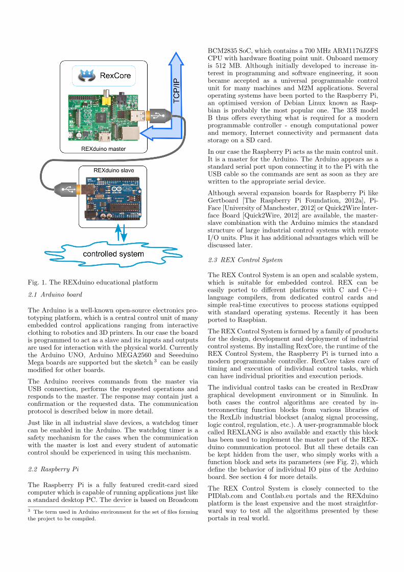
Fig. 1. The REXduino educational platform
2.1 Arduino board
The Arduino is a well-known open-source electronics pro-totyping platform, which is a central control unit of manyembedded control applications ranging from interactiveclothing to robotics and 3D printers. In our case the boardis programmed to act as a slave and its inputs and outputsare used for interaction with the physical world. Currentlythe Arduino UNO, Arduino MEGA2560 and SeeeduinoMega boards are supported but the sketch 3 can be easilymodified for other boards.
The Arduino receives commands from the master viaUSB connection, performs the requested operations andresponds to the master. The response may contain just aconfirmation or the requested data. The communicationprotocol is described below in more detail.
Just like in all industrial slave devices, a watchdog timercan be enabled in the Arduino. The watchdog timer is asafety mechanism for the cases when the communicationwith the master is lost and every student of automaticcontrol should be experienced in using this mechanism.
2.2 Raspberry Pi
The Raspberry Pi is a fully featured credit-card sizedcomputer which is capable of running applications just likea standard desktop PC. The device is based on Broadcom
3 The term used in Arduino environment for the set of files formingthe project to be compiled.
BCM2835 SoC, which contains a 700 MHz ARM1176JZFSCPU with hardware floating point unit. Onboard memoryis 512 MB. Although initially developed to increase in-terest in programming and software engineering, it soonbecame accepted as a universal programmable controlunit for many machines and M2M applications. Severaloperating systems have been ported to the Raspberry Pi,an optimised version of Debian Linux known as Rasp-bian is probably the most popular one. The 35$ modelB thus offers everything what is required for a modernprogrammable controller - enough computational powerand memory, Internet connectivity and permanent datastorage on a SD card.
In our case the Raspberry Pi acts as the main control unit.It is a master for the Arduino. The Arduino appears as astandard serial port upon connecting it to the Pi with theUSB cable so the commands are sent as soon as they arewritten to the appropriate serial device.
Although several expansion boards for Raspberry Pi likeGertboard [The Raspberry Pi Foundation, 2012a], Pi-Face [University of Manchester, 2012] or Quick2Wire Inter-face Board [Quick2Wire, 2012] are available, the master-slave combination with the Arduino mimics the standardstructure of large industrial control systems with remoteI/O units. Plus it has additional advantages which will bediscussed later.
2.3 REX Control System
The REX Control System is an open and scalable system,which is suitable for embedded control. REX can beeasily ported to different platforms with C and C++language compilers, from dedicated control cards andsimple real-time executives to process stations equippedwith standard operating systems. Recently it has beenported to Raspbian.
The REX Control System is formed by a family of productsfor the design, development and deployment of industrialcontrol systems. By installing RexCore, the runtime of theREX Control System, the Raspberry Pi is turned into amodern programmable controller. RexCore takes care oftiming and execution of individual control tasks, whichcan have individual priorities and execution periods.
The individual control tasks can be created in RexDrawgraphical development environment or in Simulink. Inboth cases the control algorithms are created by in-terconnecting function blocks from various libraries ofthe RexLib industrial blockset (analog signal processing,logic control, regulation, etc.). A user-programmable blockcalled REXLANG is also available and exactly this blockhas been used to implement the master part of the REX-duino communication protocol. But all these details canbe kept hidden from the user, who simply works with afunction block and sets its parameters (see Fig. 2), whichdefine the behavior of individual IO pins of the Arduinoboard. See section 4 for more details.
The REX Control System is closely connected to thePIDlab.com and Contlab.eu portals and the REXduinoplatform is the least expensive and the most straightfor-ward way to test all the algorithms presented by theseportals in real world.

Arduino_UNO
DO2
DO3_PWM
DO4
DO5_PWM
DO6_PWM
DO9_PWM
DO10_PWM
DO11_PWM
DO12
DO13
DO_A0
DO_A1
DO_A2
DO_A3
DO_A4
DO_A5
CNT2R
CNT2E
CNT3R
CNT3E
userSend
iEerr_code
err_subcodecomm_status
DI2DI3DI4DI5DI6DI7DI8DI9
DI10DI11
DI_A0DI_A1DI_A2DI_A3DI_A4DI_A5
AI0AI1AI2AI3AI4AI5
CNT2CNT3
OW_2_3_dataOW_4_5_dataOW_6_9_data
OW_10_11_dataOW_A0_A1_dataOW_A2_A3_data
userRecv
Fig. 2. Function block for Arduino UNO and its parame-ters
Process value
PIDU
dvsppvtvhvMANIH
mv
dmv
de
SAT
MDL
u y
CNR_setpoint
3.7
CNB_MAN_MODE
off
Fig. 3. Simulated PID control loop using the RexLibfunction blocks
3. WORKFLOW
The use of the REXduino educational platform is veryeasy, especially for users who are familiar with Simulink.But neither knowledge nor license of Simulink is requiredto get started with the development of real-time controlsystems. Only the simulation phase is affected if Simulinklicense is not available. The typical steps during thedevelopment of control algorithm are described in thefollowing sections.
3.1 Pure simulation
The first step when creating control systems involve theanalysis of the controlled system followed by the designof the control algorithm. The control algorithm is con-structed from function blocks of the RexLib industrialblockset. No programming skills are required, the userjust drags and drops blocks and connecting lines. A simplePID control loop based on industry-proven algorithms canbe created within a few mouse clicks (see Fig. 3). Thecontrolled system is present in the form of a mathematicalmodel. The behavior and internal structure of the functionblocks is described in more detail in REX Controls [2013a].
3.2 The first physical interaction
As soon as the simulation results comply with all require-ments, we can switch from simulation to physical world.For this purpose only the Arduino board is used, it isconnected directly to desktop PC or notebook via theUSB cable. The model in the scheme is replaced by theREXduino master block and a SLEEP block must beintroduced to run the control algorithm in ”real-time” (seeFig. 4). The discrete numeric solver with fixed step size set
SLEEP
Process value
PIDU
dvsppvtvhvMANIH
mv
dmv
de
SAT
CNR_setpoint
3.7
CNB_MAN_MODE
off
Arduino_UNO
DO2
DO3_PWM
DO4
DO5_PWM
DO6_PWM
DO9_PWM
DO10_PWM
DO11_PWM
DO12
DO13
DO_A0
DO_A1
DO_A2
DO_A3
DO_A4
DO_A5
CNT2R
CNT2E
CNT3R
CNT3E
userSend
iEerr_code
err_subcodecomm_status
DI2DI3DI4DI5DI6DI7DI8DI9
DI10DI11
DI_A0DI_A1DI_A2DI_A3DI_A4DI_A5
AI0AI1AI2AI3AI4AI5
CNT2CNT3
OW_2_3_dataOW_4_5_dataOW_6_9_data
OW_10_11_dataOW_A0_A1_dataOW_A2_A3_data
userRecv
Fig. 4. PID control loop using the REXduino master block
to the same value as in the SLEEP block must be used.The step size defines the sampling period of the controlalgorithm.
The user can then execute the Simulink scheme just like inthe case of pure simulation, only the PID control algorithmis now fed by real-world data acquired from the analoginput of the Arduino board and the manipulated variable(output of the controller) is sent to PWM output.
This simple and straightforward step from simulation tophysical world is especially useful for control educationpurposes as the students remain in the Simulink envi-ronment which is familiar to them. Moreover, the tuningof parameters or updating the control algorithm is veryquick, there is neither need to compile the project nortransfer any files. Sampling frequencies of up to 50 Hz canbe used, which is sufficient for many educational plants.The main factor limiting the sampling frequency is thenon-real-time behavior of Simulink running on a standardPC.
This step would not be possible with Raspberry Pi-specificinterface board, which is a reason why the Arduino boardis so valuable for the REXduino educational platform.
3.3 Real-time control
The last step of creating a real-time control system isdeployment of the algorithm on the target platform. Thisstep is very easy with the REXduino platform as well,the only thing the user has to do is to configure the real-time executive of the REX Control System. The controlalgorithm remains the same as in the previous step.
Configuration of the executive consists of defining thetarget platform (Linux in the case of Raspbian) and theexecution period of the control algorithm. The controlalgorithm from the previous step is referred to by theTASK block connected to the Level0 output (see Fig. 7).There can be more control tasks in general, and eachof them can have its own execution period and priority.In Raspbian the REXduino platform allows samplingfrequencies of up to 200 Hz, depending on the complexityof the control algorithm and number of input/outputsignals.

The project is then compiled by the RexComp compilerand sent to the Raspberry Pi, where it is executed byRexCore, the runtime of the REX Control System.
Natural part of the REX Control System is the abilityto monitor the control algorithm in real-time and changethe parameters of individual function blocks. The on-linemonitoring via TCP/IP connection is available in theRexView diagnostic program or directly in the RexDrawdevelopment tool. The user is thus allowed to tune thecontrol algorithm in the loop, without the necessity to stopit and compile it once again.
The REX Control System also offers advanced tools fordata storage and further processing. The measured dataand variables of the control algorithm are stored in thememory of Raspberry Pi from where it can be retrievedusing the RexTrend utility. This utility reads the dataand exports them in various formats including M-file forgenerating Matlab figures.
4. THE REXDUINO PROTOCOL
The REXduino protocol is a set of very simple commands,which define the operating modes of individual Arduinopins, set the outputs and read the inputs. Each commandis terminated by a semicolon.
In the initialization phase the REXduino master startscommunication and sends commands to change pin modesto the desired ones. Once the REXduino slave reports thatall pins have been switched to the requested modes, themaster starts polling data and updating the outputs.
4.1 Pin modes
There are several modes the pins of the Arduino can beconfigured for:
I - Digital inputThis mode is used for reading on/off values.
J - Digital input with pullupThis mode is used for reading of e.g. buttons or switcheswhich connect the pin to ground only when pressed. If notconnected, the pin is pulled to HIGH state.
O - Digital output, default LOWThis mode is used for generating on/off signals and can beused for powering of low-consumption circuitry. The pin isset to LOW upon initialization.
Q - Digital output, default HIGHIn this case the output pin is set to HIGH by default.
A - Analog inputThis mode is used for reading the 10-bit analog inputs ofthe Arduino (pins A0 to An).
P - PWM outputIn this mode the pin generates high-frequency pulses whoseduty cycle can be defined with 8-bit precision. Availableonly on pins marked by ∼.
C - CounterThe counter mode is available on pins 2 and 3. It employsinterrupts and counts rising edges occurring on the pin.Pins 4 and 5 in B mode define the counting direction forpins 2 and 3 respectively.
E - Encoder signal AThis mode is used for evaluating encoder signals. It isavailable on pins 2 and 3. Both rising and falling edgesof signal A trigger an interrupt routine. Signals on pins 4and 5 in B mode are used to determine the direction ofrotation.
B - Encoder signal B or counter DIRThis mode is available on pins 4 and 5 and must be usedfor proper function of counter/encoder mode on pins 2 and3 respectively.
W - 1-Wire temperatureIn this mode the pin serves as data input/output on 1-Wirebus. The temperature sensors DS18B20, DS18S20 andDS1822 are supported.
4.2 REXduino commands
Table 1 lists some of the commands and responses ofthe REXduino protocol. Commands for reading or settingmore inputs/outputs by one command are not listed forclarity. See REX Controls [2013b] for full description.
Initialize communicationCommand: C 0 ;Response: C ’0’ ;
Set pin modeCommand: M nPin mode ;Response: M nPin mode ;
Read analog inputCommand: A nPin ;Response: A nPin BH BL ;
Set PWM output (analog output)Command: P nPin value ;Response: P nPin value ;
Read digital inputCommand: I nPin ;Response: I nPin state ;
Set digital outputCommand: O nPin state ;Response: O nPin state ;
Read 1-Wire temperatureCommand: T nPin ;Response: T nPin status ;Response: T nPin status nS B1 B2 ;
Read counter or encoder valueCommand: N nPin status ;Response: N nPin status B1 B2 B3 B4 ;
User-defined commandCommand: U B1 B2 B3 B4 ;Response: U B1 B2 B3 B4 ;
Table 1. Commands of the REXduino protocol
The User-defined command is prepared for easy customiza-tion of the platform for individual cases (custom func-tions, communication with I2C or SPI devices, etc.). BothREXduino master and slave implementations are open-source thus it is quite easy to add arbitrary commandsand functionality.

Fig. 5. Communication with the REXduino slave from theserial line monitor
Fig. 6. Motor-generator model controlled by the REX-duino platform
The majority of commands exist in two versions. The firstone is used by computers and has been already listed inTable 1. The other version of the command is lower-caseand is human-readable. It is intended for use in the serialline monitor, which is useful for verification of hardwareconnections to individual sensors as shown in Fig. 5.
5. EXAMPLES
5.1 Angular velocity control
The first system which can be controlled by the REXduinoplatform is a motor-generator example. One DC motoris controlled by PWM output of the Arduino which isconnected to the base of an NPN transistor switching thecurrent through the motor on and off. The other DC motoris driven by the first one via an elastic belt and generatescurrent as it revolves (see Fig. 6).
Therefore the angular velocity of the generating motorcan be measured by the analog input of the Arduino. Thesignal is very noisy so it is necessary to suppress the highfrequencies by a Kalman-filter based filter KDER first (seeFig. 7 and then it is possible to close the angular velocityPID control loop to suppress the repetitive disturbancecaused by the improperly aligned axis of the drive wheel.The effect of PID control loop is evident from Fig. 8.
Fig. 7. Configuration of the real-time control algorithm inthe REX Control System
Fig. 8. Engaging the PID controller eliminates the mis-alignment of the drive wheel
5.2 Laboratory helicopter control
Another application for the REXduino platform was theretrofitting of an almost vintage CE150 laboratory heli-copter model, which was originally controlled by a PCequipped with an ISA plug-in card. The current versionof the model is controlled by a PCI card [Humusoft, 2013].
The helicopter is a 2x2 MIMO system, it has two propellerswhose speed can be controlled by PWM signals. Theelevation and horizontal rotation is measured by tworotary encoders. The helicopter has also a movable massinside its body to allow dislocation of the centre of mass.The location of the mass can be changed by a small motorwhich is controlled by two digital outputs.
All these signals are available on the REXduino platformtherefore the conversion to the new control system wasstraightforward and the model is fully functional aftermany years in the cabinet.
Although the main propeller influences mainly the eleva-tion, the azimuth is affected as well. The tail propeller alsoinfluences both outputs having the main impact on the az-imuth. In other words, there are significant crosscouplingsin the helicopter model.
A cascade of P and PID controller on each propeller with afeedforward action derived from the other propeller allowsstabilization of the helicopter in the given elevation whilechanging the azimuth, which is shown in Fig. 9.

Fig. 9. Stabilization of the helicopter model and azimuthcontrol
5.3 Electrical boiler control
The last example of use includes a set of DS18B20 1-Wiretemperature sensors connected to the Arduino, whichmeasure temperature in 5 rooms of a building as well asthe outside temperature and the heating and returningwater to the electrical boiler (Protherm Ray 12K). ThePWM output of the Arduino is used for defining thedesired temperature of the heating water and one digitaloutput is connected to a relay which replaces the originalthermostat.
The REXduino platform allowed to upgrade the heatingsystem from simple thermostat on/off control to advancedequitherm control at negligible cost. Moreover, it allowsthe owner to monitor the building and the boiler remotelyover the Internet.
6. OTHER USES OF THE REXDUINO PLATFORM
The REXduino platform is not limited to feedback controltasks, it can be used on the model side in hardware-in-the-loop simulations. The function block library ofthe REX Control System contains also function blocksfor simulation of continuous-time systems, therefore it ispossible to create complex models of the real plants. Againit is possible to change the parameters of the model in real-time, inject disturbances, etc., so the control system canbe tested thoroughly.
Another field of application might be the control of batchexperiments, where some sequence of actions has to berepeated (e.g. switching the lamps on and off at givenintervals, opening a valve when target temperature isreached, etc.). Plus it can serve as a datalogger duringthe experiments as all the measured data can be stored inthe RAM or on the SD card of the Raspberry Pi.
Beyond the scope of the REXduino educational platform,it is also possible to install additional drivers of theREX Control System to the Raspberry Pi to enhance itsfeatures. The Raspberry Pi can then act as Modbus TCPMaster or Slave and exchange data with true industrialI/O devices.
7. HOLY GRAIL IN CONTROL EDUCATION?
The educational platform consisting of an Arduino board,Raspberry Pi computer and the REX Control System pre-sented in this paper opens an extremely inexpensive andstraightforward path from simulation to real-time physicalcomputing and control. The platform requires negligibleinitial knowledge in programming, electronics, control the-ory or industrial communication standards therefore thestudent’s first on/off control loop can be closed within min-utes, which encourages the student and raises the interest.The platform is very open so it offers enough opportunitiesfor in-depth study in any of the above mentioned fieldsonce the student decides to do so. Both students and aca-demicians benefit from very simple interface, steep learn-ing curve and compatibility with Simulink and the PID-lab.com and Contlab.eu portals. The price/performanceratio is also excellent therefore the authors believe thatthe platform might be considered (with a little bit ofexaggeration) the Holy Grail in control education.
REFERENCES
Arduino. Arduino open-source prototyping platform.http://www.arduino.cc, 2012.
Pavel Balda, Milos Schlegel, and Milan Stetina. Ad-vanced control algorithms + Simulink compatibility +Real–time OS = REX. In Preprints of the 16th IFACWorld Congress, Prague, Czech Republic, 2005.
Humusoft. CE150 helicopter model.http://www.humusoft.cz/produkty/models/ce150/,2013.
Quick2Wire. Quick2Wire Interface Board.http://www.quick2wire.com, 2012.
REX Controls. REX system function blocks – referencemanual, 2.07 edition, 2013a.
REX Controls. REXduino protocol – user guide, 2.07edition, 2013b.
The Raspberry Pi Foundation. Gertboard.http://www.raspberrypi.org/archives/tag/gertboard,2012a.
The Raspberry Pi Foundation. Raspberry Pi.http://www.raspberrypi.org, 2012b.
University of Manchester. Pi-Face Digital Interface.http://pi.cs.man.ac.uk/interface.htm, 2012.


