REVOSHIFT Shifter - Manuals & Technical DocumentsDealer's Manual REVOSHIFT Shifter SL-RS47 SL-RS45...
16
(English) DM-SL0002-03 Dealer's Manual REVOSHIFT Shifter SL-RS47 SL-RS45 SL-RS36 SL-RS35 SL-RS34 SL-RS25
Transcript of REVOSHIFT Shifter - Manuals & Technical DocumentsDealer's Manual REVOSHIFT Shifter SL-RS47 SL-RS45...

(English) DM-SL0002-03
Dealer's Manual
REVOSHIFT Shifter
SL-RS47SL-RS45SL-RS36SL-RS35SL-RS34SL-RS25
2
IMPORTANT NOTICE
• This dealer's manual is intended primarily for use by professional bicycle mechanics. Users who are not professionally trained for bicycle assembly should not attempt to install the components themselves using the dealer's manuals.If any part of the information on the manual is unclear to you, do not proceed with the installation. Instead, contact your place of purchase or a local bicycle dealer for their assistance.
• Make sure to read all instruction manuals included with the product.
• Do not disassemble or modify the product other than as stated in the information contained in this dealer's manual.
• All dealer's manuals and instruction manuals can be viewed on-line on our website (http://si.shimano.com).
• Please observe the appropriate rules and regulations of the country, state or region in which you conduct your business as a dealer.
For safety, be sure to read this dealer's manual thoroughly before use, and follow it for correct use.
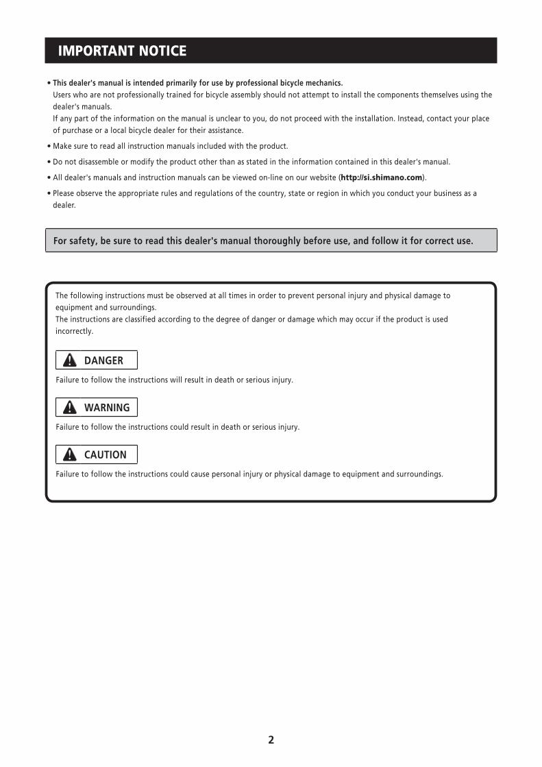
The following instructions must be observed at all times in order to prevent personal injury and physical damage toequipment and surroundings.The instructions are classified according to the degree of danger or damage which may occur if the product is usedincorrectly.
DANGER
Failure to follow the instructions will result in death or serious injury.
WARNING
Failure to follow the instructions could result in death or serious injury.
CAUTION
Failure to follow the instructions could cause personal injury or physical damage to equipment and surroundings.
3
TO ENSURE SAFETY
WARNING
• When installing components, be sure to follow the instructions that are given in the instruction manuals. It is recommended that you use only genuine Shimano parts. If parts such as bolts and nuts become loose or damaged, the bicycle may suddenly fall over, which may cause serious injury. In addition, if adjustments are not carried out correctly, problems may occur, and the bicycle may suddenly fall over, which may cause serious injury.
• Be sure to wear safety glasses or goggles to protect your eyes while performing maintenance tasks such as replacing parts.
• After reading the dealer's manual thoroughly, keep it in a safe place for later reference.
NOTE
Be sure to also inform users of the following:
• Be sure to keep turning the crank during the lever operation.
• You should periodically wash the chainrings in a neutral detergent. In addition, cleaning the chain with neutral detergent and lubricating it can be an effective way of extending the useful life of the chainrings and the chain.
• Products are not guaranteed against natural wear and deterioration from normal use and aging.
• For maximum performance we highly recommend Shimano lubricants and maintenance products.
For Installation to the Bicycle, and Maintenance:
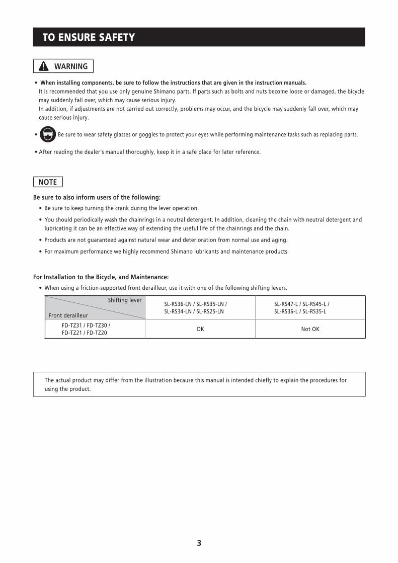
• When using a friction-supported front derailleur, use it with one of the following shifting levers.
Shifting lever
Front derailleur
SL-RS36-LN / SL-RS35-LN / SL-RS34-LN / SL-RS25-LN
SL-RS47-L / SL-RS45-L / SL-RS36-L / SL-RS35-L
FD-TZ31 / FD-TZ30 / FD-TZ21 / FD-TZ20
OK Not OK
The actual product may differ from the illustration because this manual is intended chiefly to explain the procedures for using the product.
4
INSTALLATION
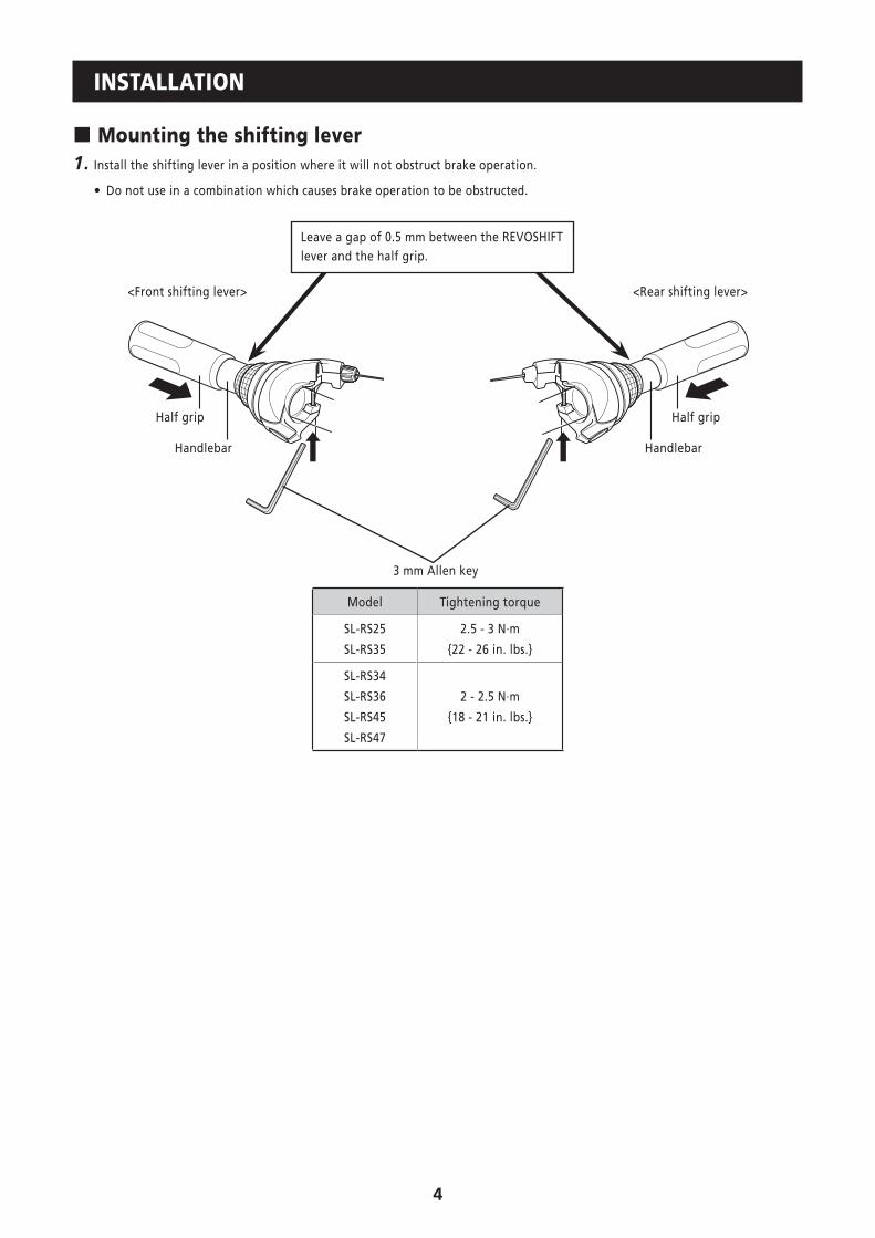
� Mounting the shifting lever1. Install the shifting lever in a position where it will not obstruct brake operation.
• Do not use in a combination which causes brake operation to be obstructed.
3 mm Allen key
Handlebar Handlebar
Half grip Half grip
Leave a gap of 0.5 mm between the REVOSHIFT lever and the half grip.
<Front shifting lever> <Rear shifting lever>
Model Tightening torque
SL-RS25
SL-RS35
2.5 - 3 N·m
{22 - 26 in. lbs.}
SL-RS34
SL-RS36
SL-RS45
SL-RS47
2 - 2.5 N·m
{18 - 21 in. lbs.}
5
ADJUSTMENT
Be sure to follow the sequence described below.
� Adjustment of the front shifting lever
(1) Low adjustment
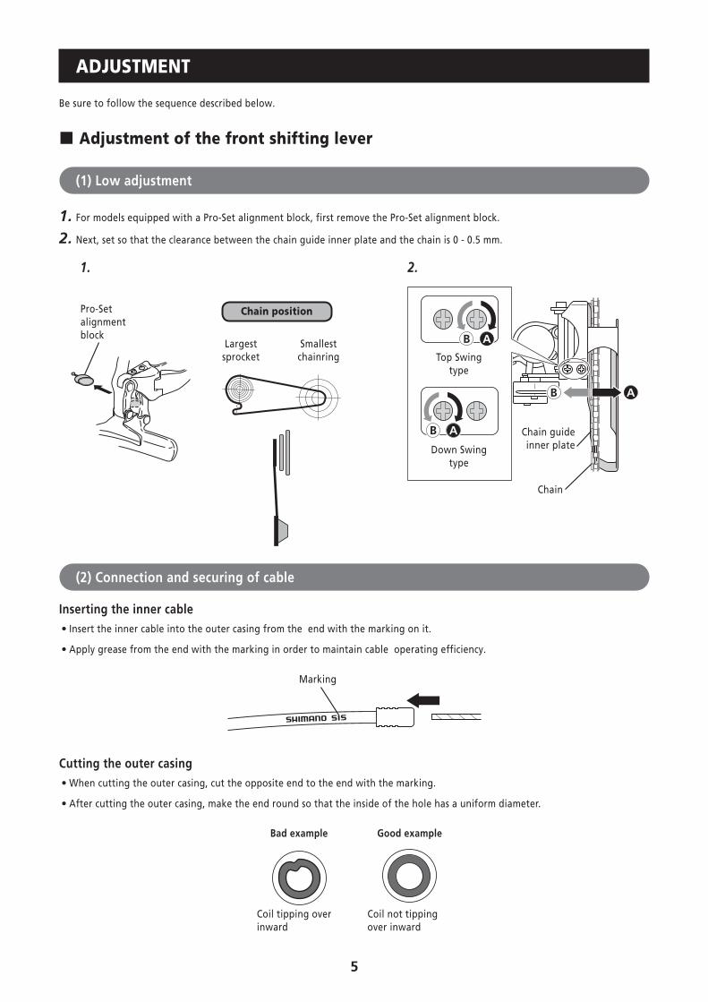
1. For models equipped with a Pro-Set alignment block, first remove the Pro-Set alignment block.
2. Next, set so that the clearance between the chain guide inner plate and the chain is 0 - 0.5 mm.
B A
B A
B A
1. 2.
Chain
Chain guide inner plate
Top Swing type
Down Swing type
Smallest chainring
Largest sprocket
Chain positionPro-Set alignment block
(2) Connection and securing of cable
Inserting the inner cable • Insert the inner cable into the outer casing from the end with the marking on it.
• Apply grease from the end with the marking in order to maintain cable operating efficiency.
Marking
Cutting the outer casing • When cutting the outer casing, cut the opposite end to the end with the marking.
• After cutting the outer casing, make the end round so that the inside of the hole has a uniform diameter.
Good example
Coil not tipping over inward
Bad example
Coil tipping over inward
6
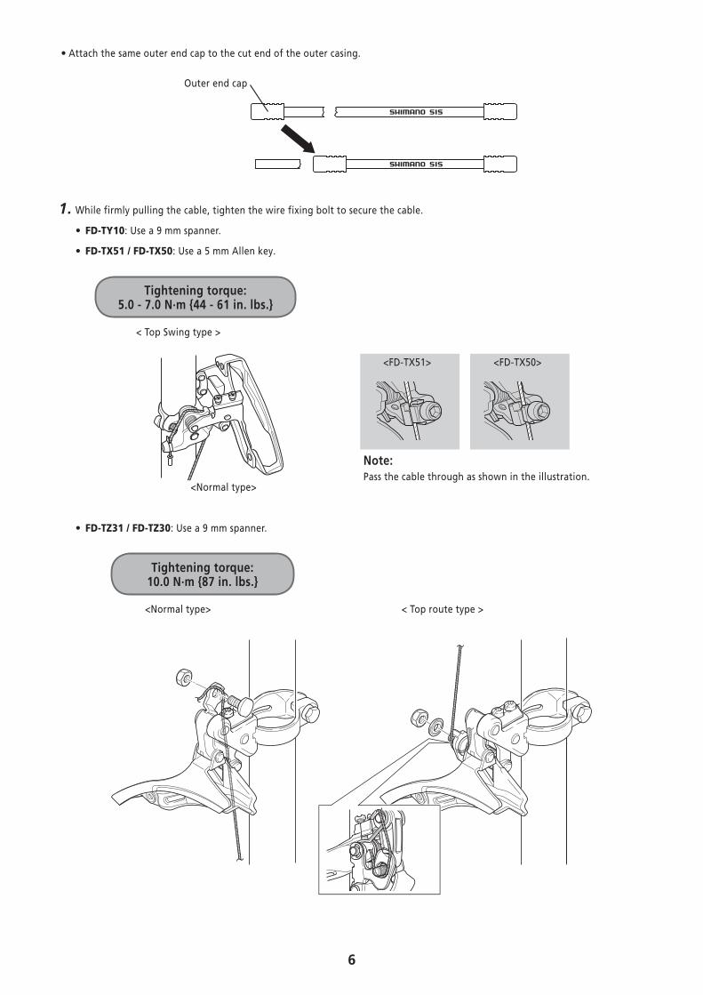
• Attach the same outer end cap to the cut end of the outer casing.
Outer end cap
1. While firmly pulling the cable, tighten the wire fixing bolt to secure the cable.
• FD-TY10: Use a 9 mm spanner.
• FD-TX51 / FD-TX50: Use a 5 mm Allen key.
Tightening torque: 5.0 - 7.0 N·m {44 - 61 in. lbs.}
<Normal type>
<FD-TX51>
Note:Pass the cable through as shown in the illustration.
<FD-TX50>
< Top Swing type >
• FD-TZ31 / FD-TZ30: Use a 9 mm spanner.
<Normal type> < Top route type >
Tightening torque: 10.0 N·m {87 in. lbs.}
7
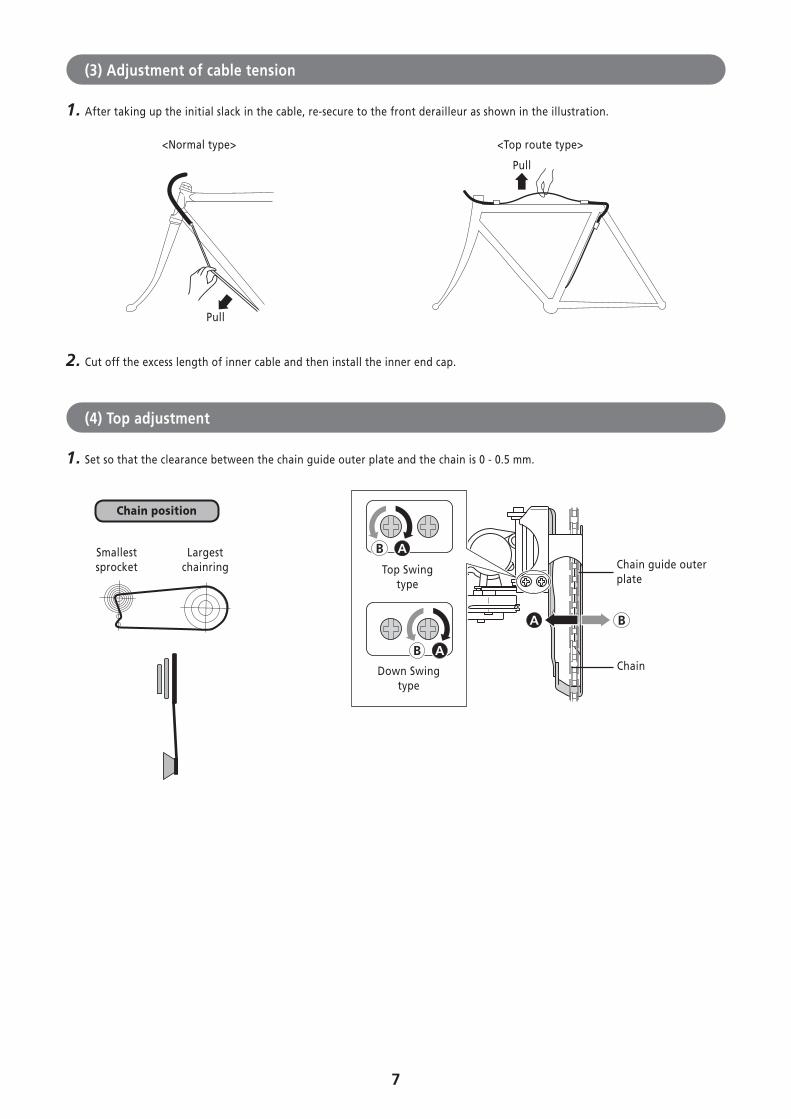
(3) Adjustment of cable tension
1. After taking up the initial slack in the cable, re-secure to the front derailleur as shown in the illustration.
<Normal type> <Top route type>
Pull
Pull
2. Cut off the excess length of inner cable and then install the inner end cap.
(4) Top adjustment
1. Set so that the clearance between the chain guide outer plate and the chain is 0 - 0.5 mm.
A B
B A
B AChain
Chain guide outer plate
Largest chainring
Smallest sprocket
Chain position
Top Swing type
Down Swing type
8
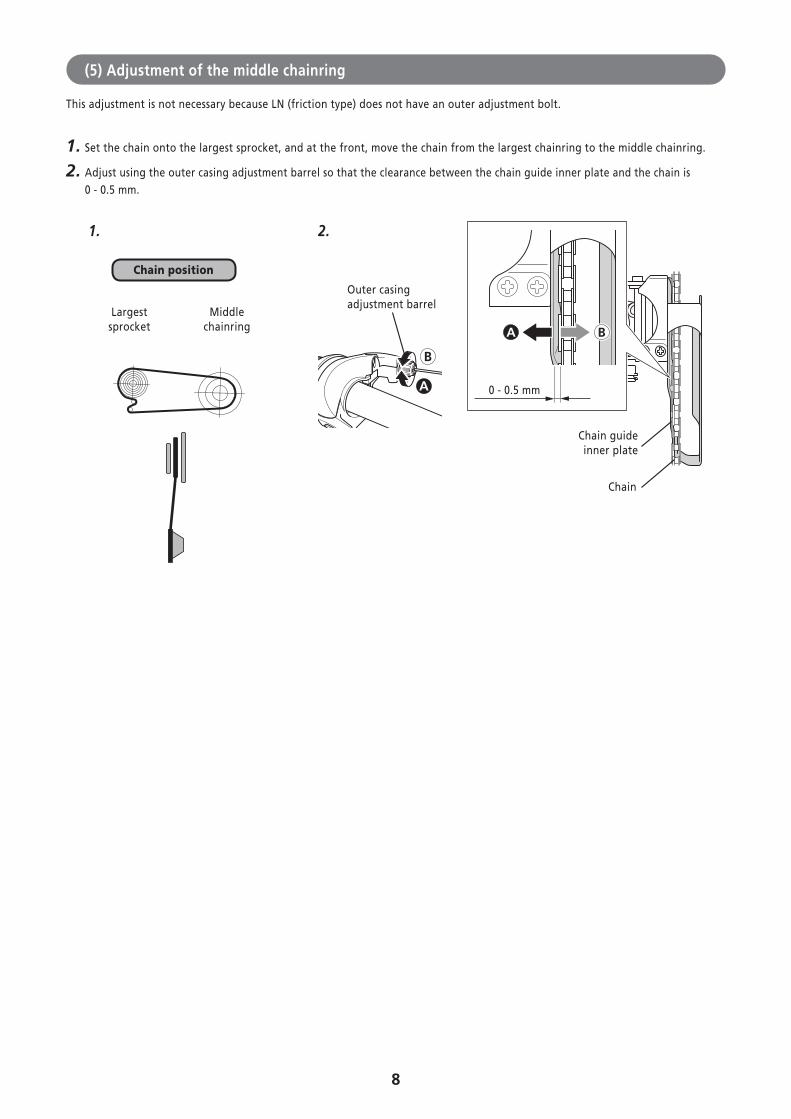
(5) Adjustment of the middle chainring
This adjustment is not necessary because LN (friction type) does not have an outer adjustment bolt.
1. Set the chain onto the largest sprocket, and at the front, move the chain from the largest chainring to the middle chainring.
2. Adjust using the outer casing adjustment barrel so that the clearance between the chain guide inner plate and the chain is 0 - 0.5 mm.
A
B
BA
Middle chainring
Largest sprocket
1. 2.
Outer casing adjustment barrel
Chain
Chain guide inner plate
Chain position
0 - 0.5 mm
9
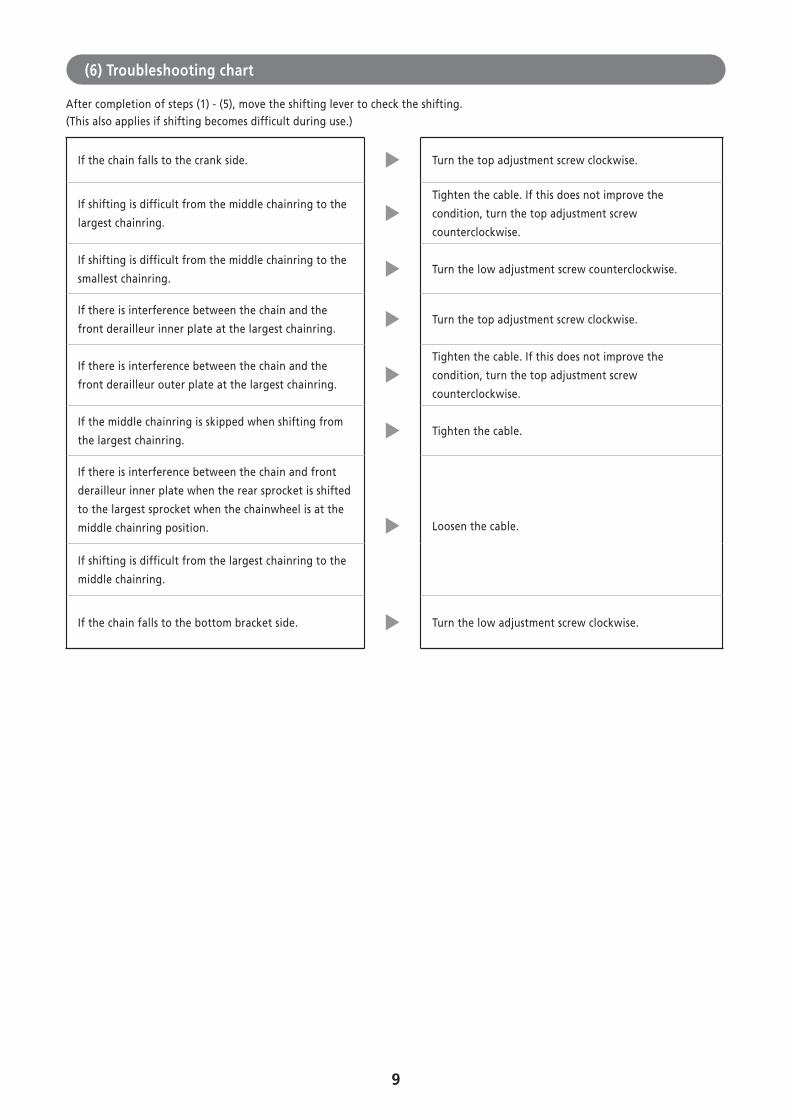
(6) Troubleshooting chart
After completion of steps (1) - (5), move the shifting lever to check the shifting.(This also applies if shifting becomes difficult during use.)
If the chain falls to the crank side. Turn the top adjustment screw clockwise.
If shifting is difficult from the middle chainring to the
largest chainring.
Tighten the cable. If this does not improve the
condition, turn the top adjustment screw
counterclockwise.
If shifting is difficult from the middle chainring to the
smallest chainring.Turn the low adjustment screw counterclockwise.
If there is interference between the chain and the
front derailleur inner plate at the largest chainring.Turn the top adjustment screw clockwise.
If there is interference between the chain and the
front derailleur outer plate at the largest chainring.
Tighten the cable. If this does not improve the
condition, turn the top adjustment screw
counterclockwise.
If the middle chainring is skipped when shifting from
the largest chainring.Tighten the cable.
If there is interference between the chain and front
derailleur inner plate when the rear sprocket is shifted
to the largest sprocket when the chainwheel is at the
middle chainring position. Loosen the cable.
If shifting is difficult from the largest chainring to the
middle chainring.
If the chain falls to the bottom bracket side. Turn the low adjustment screw clockwise.
10
� Adjustment of the rear shifting lever
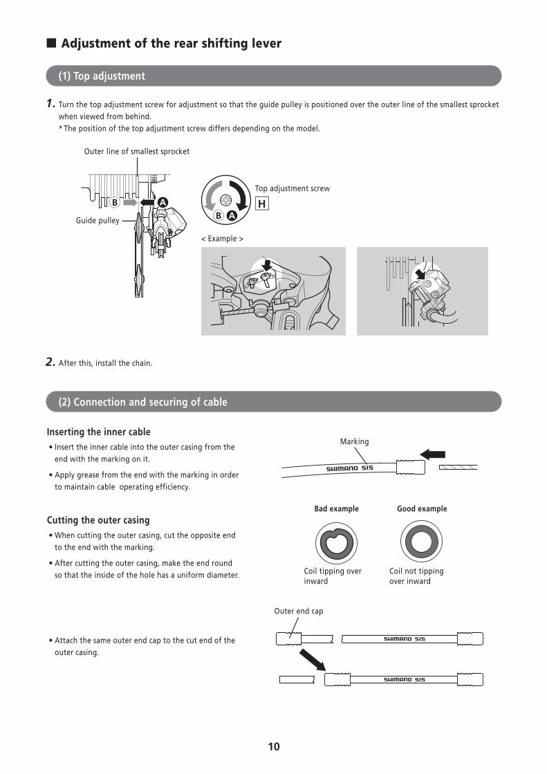
(1) Top adjustment
1. Turn the top adjustment screw for adjustment so that the guide pulley is positioned over the outer line of the smallest sprocket when viewed from behind.* The position of the top adjustment screw differs depending on the model.
ABB A
Guide pulley
Outer line of smallest sprocket
Top adjustment screw
< Example >
2. After this, install the chain.
(2) Connection and securing of cable
Inserting the inner cable • Insert the inner cable into the outer casing from the end with the marking on it.
• Apply grease from the end with the marking in order to maintain cable operating efficiency.
Marking
Cutting the outer casing • When cutting the outer casing, cut the opposite end to the end with the marking.
• After cutting the outer casing, make the end round so that the inside of the hole has a uniform diameter.
Good example
Coil not tipping over inward
Bad example
Coil tipping over inward
• Attach the same outer end cap to the cut end of the outer casing.
Outer end cap
11
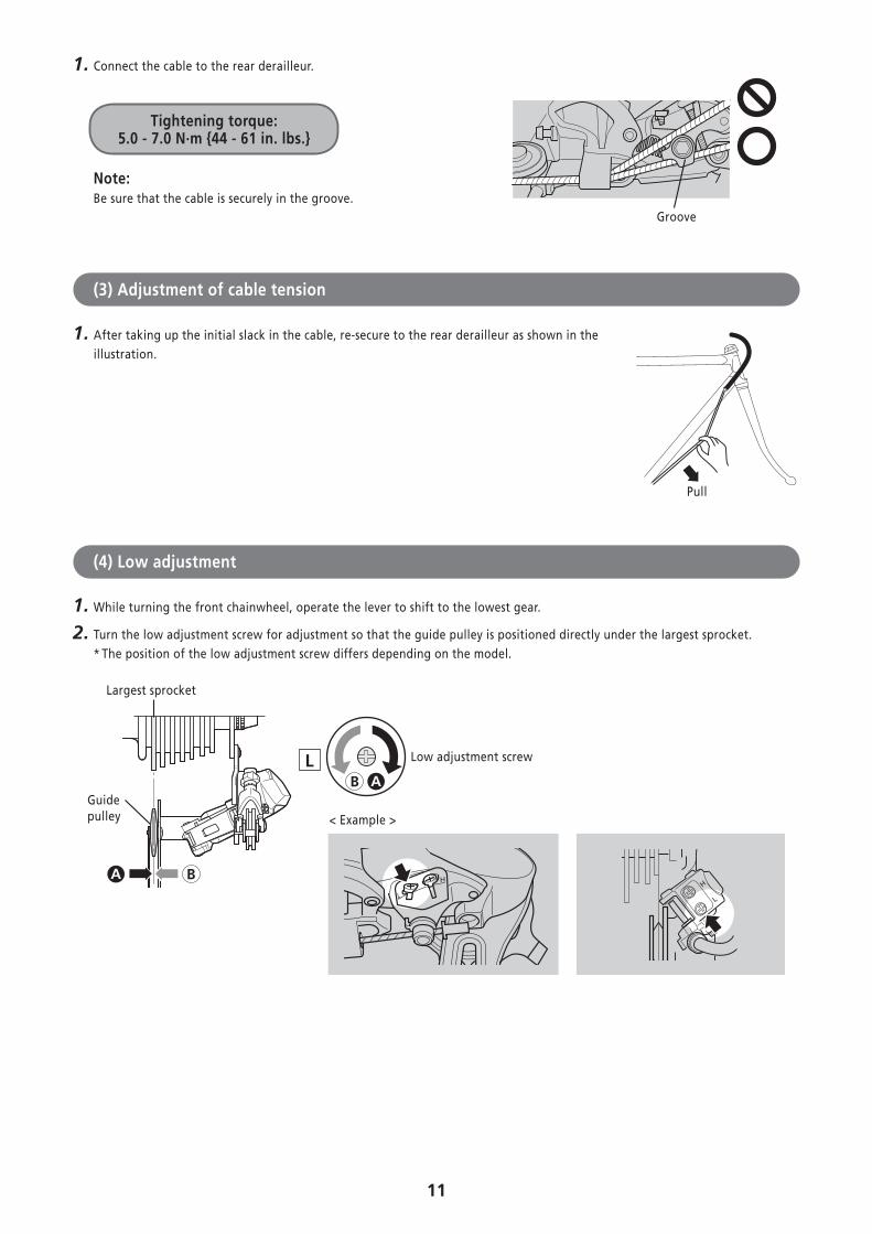
1. Connect the cable to the rear derailleur.
Tightening torque: 5.0 - 7.0 N·m {44 - 61 in. lbs.}
Note:Be sure that the cable is securely in the groove.
Groove
(3) Adjustment of cable tension
1. After taking up the initial slack in the cable, re-secure to the rear derailleur as shown in the illustration.
(4) Low adjustment
1. While turning the front chainwheel, operate the lever to shift to the lowest gear.
2. Turn the low adjustment screw for adjustment so that the guide pulley is positioned directly under the largest sprocket.* The position of the low adjustment screw differs depending on the model.
AB
BA
Guide pulley
Low adjustment screw
Largest sprocket
< Example >
Pull
12
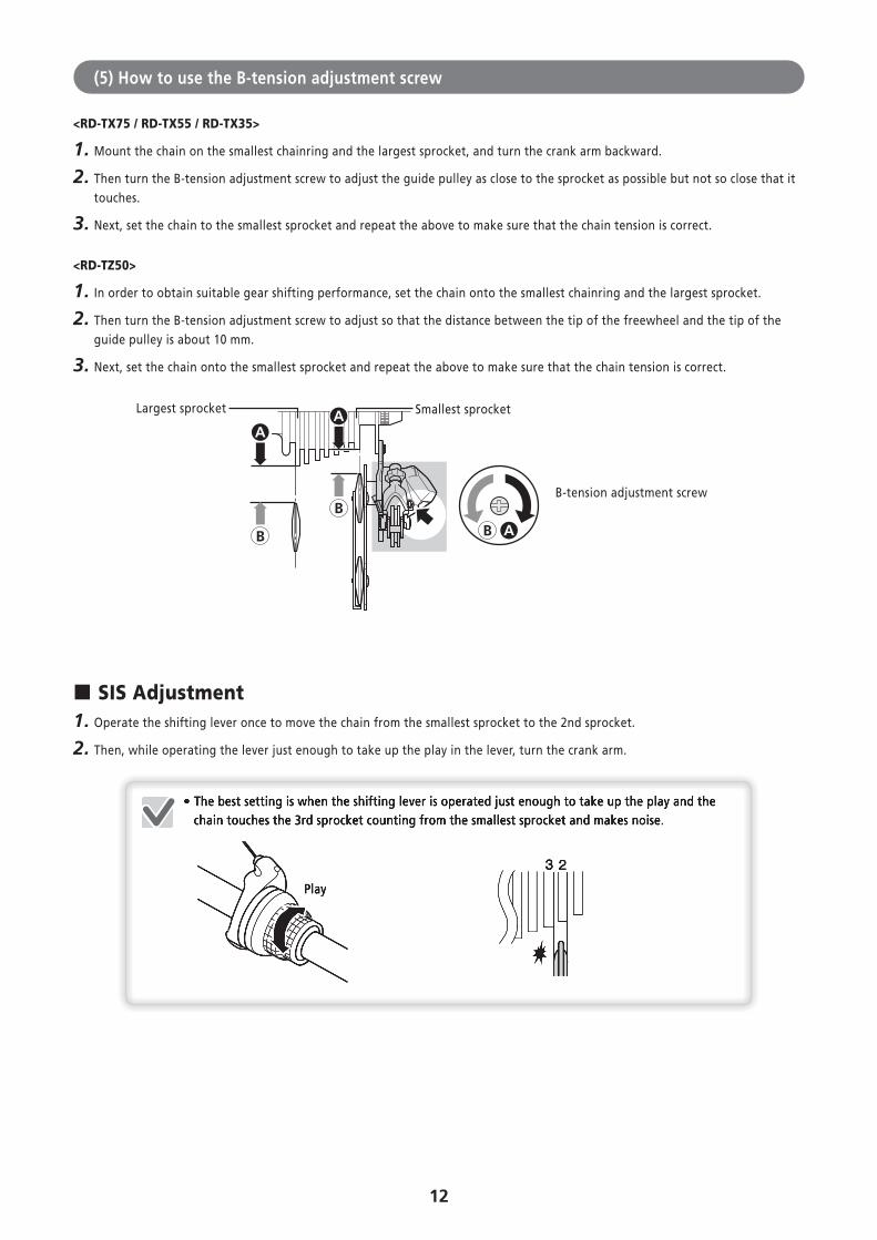
(5) How to use the B-tension adjustment screw
<RD-TX75 / RD-TX55 / RD-TX35>
1. Mount the chain on the smallest chainring and the largest sprocket, and turn the crank arm backward.
2. Then turn the B-tension adjustment screw to adjust the guide pulley as close to the sprocket as possible but not so close that it touches.
3. Next, set the chain to the smallest sprocket and repeat the above to make sure that the chain tension is correct.
<RD-TZ50>
1. In order to obtain suitable gear shifting performance, set the chain onto the smallest chainring and the largest sprocket.
2. Then turn the B-tension adjustment screw to adjust so that the distance between the tip of the freewheel and the tip of the guide pulley is about 10 mm.
3. Next, set the chain onto the smallest sprocket and repeat the above to make sure that the chain tension is correct.
AA
B
B
AB
Largest sprocket Smallest sprocket
B-tension adjustment screw
� SIS Adjustment1. Operate the shifting lever once to move the chain from the smallest sprocket to the 2nd sprocket.
2. Then, while operating the lever just enough to take up the play in the lever, turn the crank arm.
Play
• The best setting is when the shifting lever is operated just enough to take up the play and the chain touches the 3rd sprocket counting from the smallest sprocket and makes noise.
Play
• The best setting is when the shifting lever is operated just enough to take up the play and the chain touches the 3rd sprocket counting from the smallest sprocket and makes noise.
13
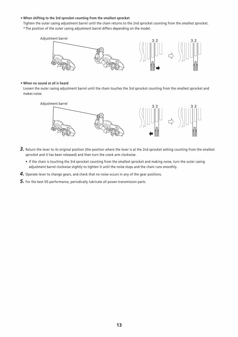
• When shifting to the 3rd sprocket counting from the smallest sprocketTighten the outer casing adjustment barrel until the chain returns to the 2nd sprocket counting from the smallest sprocket.* The position of the outer casing adjustment barrel differs depending on the model.
Adjustment barrel
• When no sound at all is heardLoosen the outer casing adjustment barrel until the chain touches the 3rd sprocket counting from the smallest sprocket and makes noise.
Adjustment barrel
3. Return the lever to its original position (the position where the lever is at the 2nd sprocket setting counting from the smallest sprocket and it has been released) and then turn the crank arm clockwise.
• If the chain is touching the 3rd sprocket counting from the smallest sprocket and making noise, turn the outer casing adjustment barrel clockwise slightly to tighten it until the noise stops and the chain runs smoothly.
4. Operate lever to change gears, and check that no noise occurs in any of the gear positions.
5. For the best SIS performance, periodically lubricate all power-transmission parts.
14
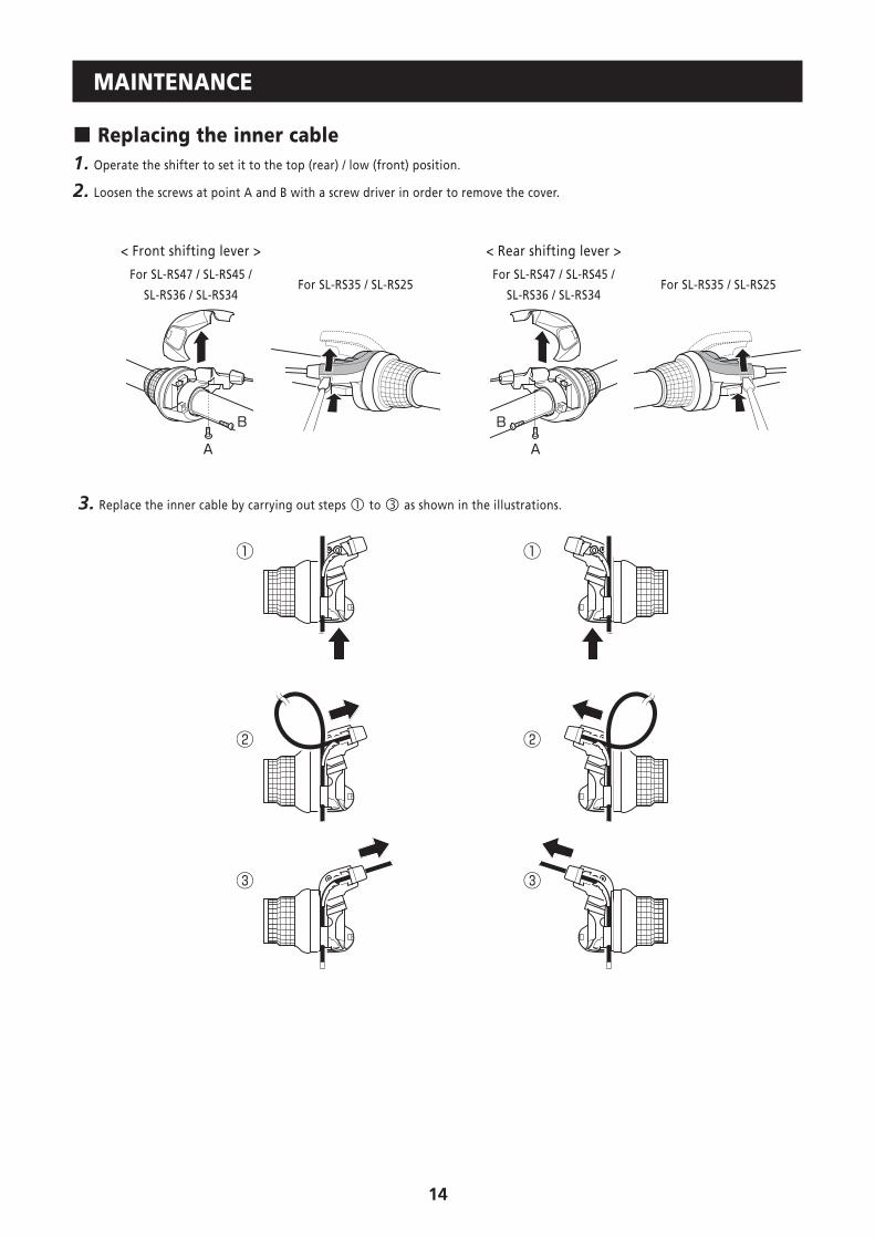
MAINTENANCE
� Replacing the inner cable1. Operate the shifter to set it to the top (rear) / low (front) position.
2. Loosen the screws at point A and B with a screw driver in order to remove the cover.
< Front shifting lever > < Rear shifting lever >
For SL-RS47 / SL-RS45 /
SL-RS36 / SL-RS34For SL-RS35 / SL-RS25
For SL-RS47 / SL-RS45 /
SL-RS36 / SL-RS34For SL-RS35 / SL-RS25
3. Replace the inner cable by carrying out steps to as shown in the illustrations.
15
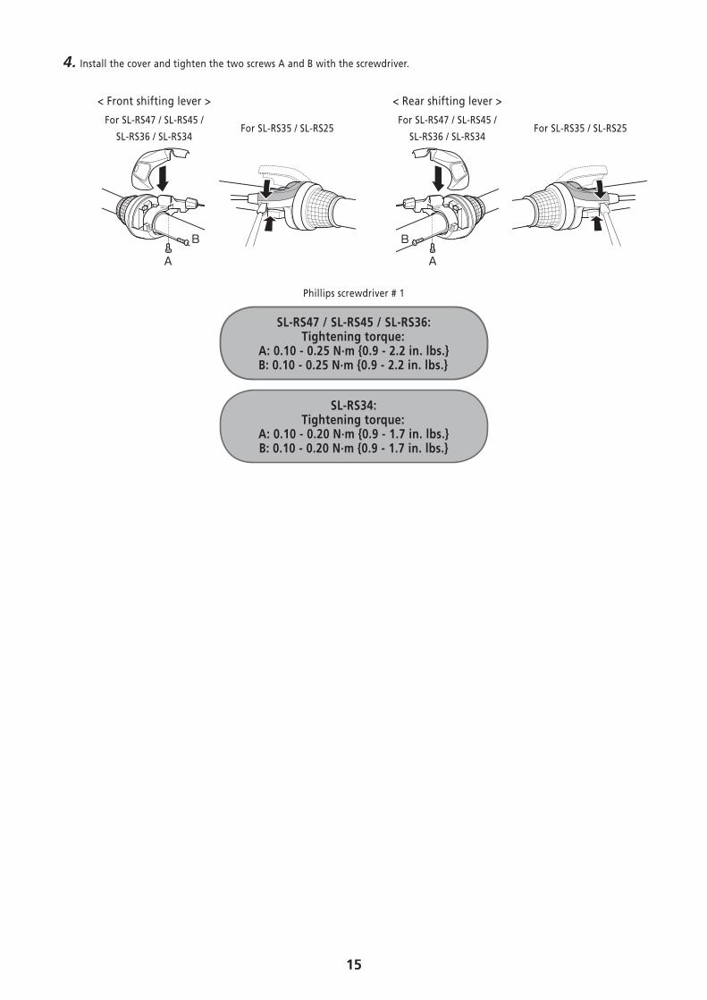
4. Install the cover and tighten the two screws A and B with the screwdriver.
< Front shifting lever > < Rear shifting lever >
For SL-RS47 / SL-RS45 /
SL-RS36 / SL-RS34For SL-RS35 / SL-RS25
For SL-RS47 / SL-RS45 /
SL-RS36 / SL-RS34For SL-RS35 / SL-RS25
Phillips screwdriver # 1
SL-RS47 / SL-RS45 / SL-RS36: Tightening torque:
A: 0.10 - 0.25 N·m {0.9 - 2.2 in. lbs.}B: 0.10 - 0.25 N·m {0.9 - 2.2 in. lbs.}
SL-RS34: Tightening torque:
A: 0.10 - 0.20 N·m {0.9 - 1.7 in. lbs.}B: 0.10 - 0.20 N·m {0.9 - 1.7 in. lbs.}

Please note: specifications are subject to change for improvement without notice. (English) © Dec. 2013 by Shimano Inc. HTR