Revit Foodservice Equipment Standards - cdn.ymaws.com · FCSI Revit Foodservice Equipment Standards...
37
FCSI Revit Foodservice Equipment Standards July 31, 2015 Page 1 of 37 Revit Foodservice Equipment Standards Introduction The purpose of this document is to define a set of guidelines and standards for model content creation in Revit® Architecture, Revit® MEP, and Revit® Structure for use in the Food Service Equipment Industry. Model content refers to the two‐dimensional and three‐dimensional standard component families that are used to create elements that represent manufactured food service equipment content items (for example, refrigerators, ranges, ice makers, and other commercial food service equipment). By following the guidelines and standards in this guide, content creators in the Food Service Equipment Industry will ensure the portability, compatibility and performance of their content. Significant research has been conducted in the preparation of this standard. Great care has been taken to be in close compliance with industry standards and Autodesk published guidelines such as the Revit Model Content Style Guide. (Many topics in this standard have been quoted, paraphrased or interpreted from the Autodesk Content Style Guide). The Revit Model Content Style Guide (hereafter referred to as RMCSG) details Autodesk requirements for content created by manufacturers of all kinds (it is not specifically geared toward the Food Service Equipment Industry). It also sets the minimum requirements for such content to be published by the Autodesk® Seek web service. The Autodesk Seek web service requires: • The uniform display of products offered by a single manufacturer • Complete, consistent, and accurate presentation of product data across manufacturers • The full use of Autodesk Seek search capabilities Regardless of the ultimate use or distribution channel for Food Service Equipment content built in accordance to the recommendations of this document, the above Autodesk Seek requirements are seen as industry standard best practices. Therefore, similar goals are adopted by this standard and incorporated herein. Feedback on the Standard All files and documents pertaining to the Revit Foodservice Equipment Standards can be found at http://www.fcsi.org/?page=REVITStandards and are available for all members and non‐members to access. Please send your comments on the Revit Food Service Equipment Standards and supporting documentation to the Forum at http://www.fcsi.org/forums/Topics.aspx?forum=181052 Audience This guide is intended for anyone interested in the creation of food service equipment. This includes manufacturers, content service organizations, and other content creators who have advanced knowledge of both Revit software and Revit model content creation.
Transcript of Revit Foodservice Equipment Standards - cdn.ymaws.com · FCSI Revit Foodservice Equipment Standards...
FCSI Revit Foodservice Equipment Standards July 31, 2015
Page 1 of 37
Revit Foodservice Equipment Standards
Introduction The purpose of this document is to define a set of guidelines and standards for model content creation in
Revit® Architecture, Revit® MEP, and Revit® Structure for use in the Food Service Equipment Industry.
Model content refers to the two‐dimensional and three‐dimensional standard component families that
are used to create elements that represent manufactured food service equipment content items (for
example, refrigerators, ranges, ice makers, and other commercial food service equipment).
By following the guidelines and standards in this guide, content creators in the Food Service Equipment
Industry will ensure the portability, compatibility and performance of their content. Significant research
has been conducted in the preparation of this standard. Great care has been taken to be in close
compliance with industry standards and Autodesk published guidelines such as the Revit Model Content
Style Guide. (Many topics in this standard have been quoted, paraphrased or interpreted from the
Autodesk Content Style Guide). The Revit Model Content Style Guide (hereafter referred to as RMCSG)
details Autodesk requirements for content created by manufacturers of all kinds (it is not specifically
geared toward the Food Service Equipment Industry). It also sets the minimum requirements for such
content to be published by the Autodesk® Seek web service. The Autodesk Seek web service requires:
• The uniform display of products offered by a single manufacturer
• Complete, consistent, and accurate presentation of product data across manufacturers
• The full use of Autodesk Seek search capabilities
Regardless of the ultimate use or distribution channel for Food Service Equipment content built in
accordance to the recommendations of this document, the above Autodesk Seek requirements are seen
as industry standard best practices. Therefore, similar goals are adopted by this standard and
incorporated herein.
Feedback on the Standard
All files and documents pertaining to the Revit Foodservice Equipment Standards can be found at
http://www.fcsi.org/?page=REVITStandards and are available for all members and non‐members to
access. Please send your comments on the Revit Food Service Equipment Standards and supporting
documentation to the Forum at http://www.fcsi.org/forums/Topics.aspx?forum=181052
Audience
This guide is intended for anyone interested in the creation of food service equipment. This includes
manufacturers, content service organizations, and other content creators who have advanced knowledge
of both Revit software and Revit model content creation.
FCSI Revit Foodservice Equipment Standards July 31, 2015
Page 2 of 37
Definitions:
Some definitions are in order before proceeding to specific recommendations and best practices.
Revit Category
Revit groups elements in the software within a strict hierarchy. At the top of this hierarchy is a list of
categories defined by the software. These categories define broad groupings of similar elements such as
Walls, Doors, Furniture and Casework. The category list is built into Revit and cannot be changed by the
user.
Revit Family
In his blog the Building Coderi, Jeremy Tammik offers this definition: “A Revit family is a graphic
representation of building objects and symbols. It can include geometry in 2D or 3D as well as data that
supports the definition and creation of object instances.” Families are used to define the shape, form,
physical and behavioral characteristics of individual elements used in a Revit project.
Family Types
Each Family is capable of spawning variations. Some Families have no need for variations and as such can
be thought of “Stand‐alone” Families or a “Family of One.” When a piece of equipment however comes in
more than one size or variation it would have more than one Family Type. Each Family Type is really just a
named set of variations in the Family’s parameters.
Classes of Families
There are three classes of Families in Revit:
Component Family: Depending on whom you ask or which document you read, you will find alternate
names for the Component Family. They are sometimes referred to as: “Standard Families,” “Loadable
Families” or simply “Families.” In this document, we will use the term “Component Families” since this
matches the name of the generic tool used in Revit to insert them in a project. A Component Family is a
user‐definable building component or symbol. All Families, including Component Families, must belong to
a Category and the chosen category will often endow the Family with certain behaviors, but otherwise,
the exact composition and definition of the Component Family is largely up to the author of the Family to
design and determine. Component Families are highly portable. They can be saved to external Revit files
with an RFA extension and thereby loaded into other project files quickly and easily.
System Family: A System Family is pre‐defined and built‐in to the software and cannot be changed by the
user. Many common Families in a Revit project are System Families such as Walls, Floors and Roofs. Such
Families cannot be modified in any way. However all Families, including System Families can have Family
Types. Family Types can always be modified by the user. System Families are part of all Revit project files.
They cannot be saved to external RFA files. Sharing System Family Types from one project to another
must be accomplished with the Transfer Project Standards functionality or via copy and paste.
In-Place Family: Used to model unique and special case geometry in a project. They cannot be shared
between projects and as such are not considered further in this document.
FCSI Revit Foodservice Equipment Standards July 31, 2015
Page 3 of 37
Type: A named variation in a particular Family. A Family Type will have a saved value assigned to each
parameter of the Family making it easy to swap out one variation of a Family with another. For example,
the same range might come in two widths or the same work table in two different heights. Size variations
are the most common use of Types, but they can be used to save the values of any parameter. For
example each Type could have a different model number and cut sheet reference even where there
might be little or no change geometrically.
Instance: This is the actual element selectable in the project file.
Parameters
Parameters are properties assigned to the Revit project or to specific content items in a project model.
Parameters expose interactive variables to the end user allowing them to manipulate the object, model
or project in some meaningful way. Parameters can be used to drive the size and shape of geometry,
allow variations in material or finish, control element visibility, establish loads, flow variables or nearly
limitless other possibilities.
There are a few types of Parameters. At the top level of the hierarchy, there are System Parameters and
user‐defined Parameters. A System Parameter is built into Revit and always available. A user‐defined
parameter is one created by a Revit user and may be available only in a certain Family, a certain project,
or multiple Families and projects depending on how it is defined.
User‐defined Parameters can be created in a Family file or in a Project file as either “local” or “Shared”
parameters. This really means that there are three total possibilities: Family Parameter (local), Project
Parameter (local) and Shared Parameter. “Local” is not an official Revit term, but rather a description of
their behavior. When described this way, both Family and Project Parameters can be considered local in
the sense that they would only be available within that Family or Project file. By contrast, a Shared
Parameter is defined externally in a separate “Shared Parameter file.” This means that the same
parameter definition can be used (or “shared”) between multiple Families or Projects. Shared Parameter
is an official Revit designation. Shared parameters can be used for both Family and Project parameters.
Family Parameter: exists only in the Family in which it is defined. A Family Parameter can drive geometry
and control other physical or graphical characteristics of the Family. It cannot appear in Schedules or in
Tags.
Project Parameter: exists only in the Project in which it is defined. A Project parameter is assigned to a
specific Category and will be available to all elements of that category in the project even if the
parameter is not explicitly defined in each Family. A Project Parameter can drive geometry and control
other physical or graphical characteristics of the Family. If can appear in Schedules but cannot appear in
Tags.
Shared Parameter: both Family and Project Parameters can be defined using a Shared Parameter. Shared
Parameters are defined in an external text file and are thereby available for use in any Family or project.
A Shared Parameter has a special ID designation (hidden from the user) that ensures each parameter is
unique. To ensure the integrity of Shared Parameters, it is imperative that a single Shared Parameter file
is maintained for the entire project team and ideally the entire organization. This is VERY important as
FCSI Revit Foodservice Equipment Standards July 31, 2015
Page 4 of 37
creating two parameters with exactly the same settings will NOT make them the same. Revit will see the
hidden ID designation and treat each parameter as different even if they have the same name and
settings. Careful coordination of resources is therefore imperative to ensure success when sharing
content among the extended project team. A Shared Parameter can drive geometry and control other
physical or graphical characteristics of the Family. They can appear in both Schedules and Tags.
System Parameter: these parameters are built into Revit. They require no user configuration, are always
available and can appear in both Schedules and Tags.
Type and Instance Parameters
When you define a parameter it can be applied at the Type or Instance level. Type parameters hold a
single value that is applied across all instances of a Family. Instance‐based parameters begin with a
default value in the Family file that can modified by the user to a unique value for each instance of a
Family/Type in the project. Both applications of parameters have utility in Families and projects.
Type-based Parameters: Use Type‐based for parameters that represent variations in an item from the
manufacturer; those that would require the specification of a different model or item. For example if a
product catalog lists multiple variations for an item that must be specified at the time of ordering, these
items will typically be best represented in Revit as Type‐based parameters. Dimensional parameters like
width and depth are frequently designated as type‐based.
Instance-based Parameters: Use Instance‐based for parameters that represent variations in an item that
are made onsite during installation. These adjustments make each instance slightly unique from other
items of the same Family and Type. Examples include the length of a fabricated work counter that is cut
to fit or fabricated to fit a unique installation condition.
It should be noted that the same Family can include some instance and some type‐based parameters as
appropriate. For example, a work table might use type‐based parameters for the height and depth, but
use instance‐based for the counter length.
Revit Content
Revit Content refers to any discreet item in the Revit software that can be re‐used from project to project
to represent a real item in the final built environment. This can include Families from any of the above
classes. Therefore consideration must be given to the class of Family so that proper delivery mechanisms
can be employed. For example, Component Families as noted above are portable and easily shared by
saving the Family to an RFA file. To share System Family Types, one must create a “Library Project File”
(saved as a Revit project file with an RVT extension) and copy the System Family Type therein. The
recipient can then copy or transfer the Type from this file to their own project file. In‐Place Families
cannot be shared and should not be utilized to create content that you intend to share.
Quality Revit Content
Perhaps the first challenge of creating content for Revit or any similar platform is defining exactly what
said content should seek to achieve and establishing a benchmark for how quality will be defined. RMCSG
defines quality Revit content as follows: “Quality Revit Content balances performance with design
FCSI Revit Foodservice Equipment Standards July 31, 2015
Page 5 of 37
accuracy and required levels of detail. Quality content is easy to use because it functions reliably
in a range of projects and project phases, while delivering manufactured content in a format
appropriate for architecture and engineering documentation deliverables.”
RMCSG further outlines the following quality considerations:
• Appropriate level of detail designed
• Adequate number of types created
• Flexible use of parameters
• Accuracy – complete, consistent presentation of product data.
• Standards – adheres to industry and Autodesk standards.
• Naming conventions
• Graphic guidelines
• Parameter usage
• Performance – content designed to reduce the performance impact of the family on a
project.
• Testing – thorough testing of the family parameters and types independently and in a
project environment.
Section 1: Planning Food Service Equipment Industry Revit Model
Content In order to ensure Revit model content is developed efficiently and to the standards recommended
herein, content authors should follow approved best practices and recommendations when creating
Revit families.
In its present state, Revit files cannot be saved backwards. Also as new releases of Revit are introduced,
features are added that may not have been available in previous releases. Therefore new Food Service
Equipment Industry Content should be created in a Revit release no further back than two years from the
current release, (e.g., Revit 2016 is current. Only releases 2014, 2015, and 2016 are valid for creating
new Revit content).
Recommended Family Template
All Component Families must be created from one of several Family Template files provided with the
software. A Family Template determines a few key behaviors of the Family; namely its Category and its
hosting requirements. As noted above in the “Definitions” topic, Revit includes many built‐in Categories.
Revit’s list of Categories is fairly broad in scope and is limited to overall building‐wide categorizations. As
such, it does not include a Category specifically for Food Service Equipment. Rather, Food Service
Equipment in Revit is included under the much broader category of Specialty Equipment. This category
will be used for most types of equipment. However, in selected cases, it may be appropriate to use the
Casework category for certain items.
FCSI Revit Foodservice Equipment Standards July 31, 2015
Page 6 of 37
Hosted vs Free-Standing Templates
Both Specialty Equipment and Casework categories include free‐standing and host‐based templates. If
you choose either the Specialty Equipment wall based.rft or the Casework wall based.rft template, the
Family created will require a Wall host when inserted. This means that user of the Family will not be able
to insert the item without attaching it to a Wall in their project. If you choose the Specialty Equipment.rft
or the Casework.rft Family Template, then the Family thus created will be “free standing” meaning that it
will not require a host of any kind and can simply be inserted into a project. There are a few reasons that
you will want to consider this situation very carefully before choosing a wall based Family template.
At first it may seem logical to use a Wall‐hosted template for certain items particularly those that would
normally hang on a Wall. For example, wall mounted cabinetry. However, the Kitchen Designer may
begin his design before the Architect has completed his work. This means that the Wall elements may not
all be in place, nor may their placements be permanent. This may pose challenges and unreasonable
limitations on workflow and project schedule. Furthermore, many project teams separate geometry into
different files and link them together as a way of managing workflow and the needs of the different
disciplines working simultaneously on the project. Often such divisions are made across discipline lines
meaning that the Architect and the Kitchen Designer could possibly be working in two separate Revit files
and linking them together to coordinate their efforts. In such a case, use of Wall‐hosted Families will
prove problematic as items cannot be hosted by Walls across linked files. The element and its host MUST
be in the same Revit project.
• For these reasons, the use of “Wall Based” and “Face Based” Family Templates is not
recommended.
• It is recommended that the Specialty Equipment.rft template file be used as the primary Family
Template file for Food Service Equipment.
• In cases where it can be argued that Casework is a better choice of Category, please use the
Casework.rft Family Template instead.
Family Representations
Given the different kinds of drawings and deliverables in which a particular Family may be shown, it is
often advisable to design the content to contain more than one representation. Revit offers three levels
of detail display for views in a project. These include Coarse, Medium and Fine. Coarse is used for simple
schematic and symbolic representations typically useful in overall scale drawings and in early design
phases. Medium often shows a little more detail than Coarse and works best at larger scales and detailed
construction document views. Fine level of detail should be reserved for visualization purposes and
typically shows a high level of detail and much more realistic representations.
It is possible to include all three levels of detail in a single Component Family. An alternative approach is
to include the Coarse and Medium detail levels in one Family for use in design development and
construction document drawing sets and create a separate high detail Family for use in rendering and
visualization.
FCSI Revit Foodservice Equipment Standards July 31, 2015
Page 7 of 37
Coarse Level of Detail
When creating geometry for Coarse Level of Detail, focus on the overall form of the object. Represent
elements using two‐dimensional geometry or very simply three‐dimensional extrusions or simplified
forms. Avoid curves and fine details (such as hinges, latches, vents, louvers, knobs, etc.) that would not
plot well at ¼" = 1'‐0" or smaller scales. The purpose of the Coarse Level of Detail is to accurately depict
the overall shape and form of the element. It should be dimensionally accurate with respect to overall
depth, width and height and assist in placement and determination of required clearances for the object
in overall views. Surface details should be kept to a minimum. To draw any surface detailing that you do
include in plan and elevation views, use Symbolic Lines wherever possible. Symbolic Lines are two‐
dimensional lines and shapes that appear only in project views parallel to the one in which the Symbolic
Lines are drawn. For example, Symbolic Lines drawn in a plan view in the Family editor will display only in
plan views in the project. Symbolic Lines drawn in an elevation will only display in elevations parallel to
the one in which they are drawn.
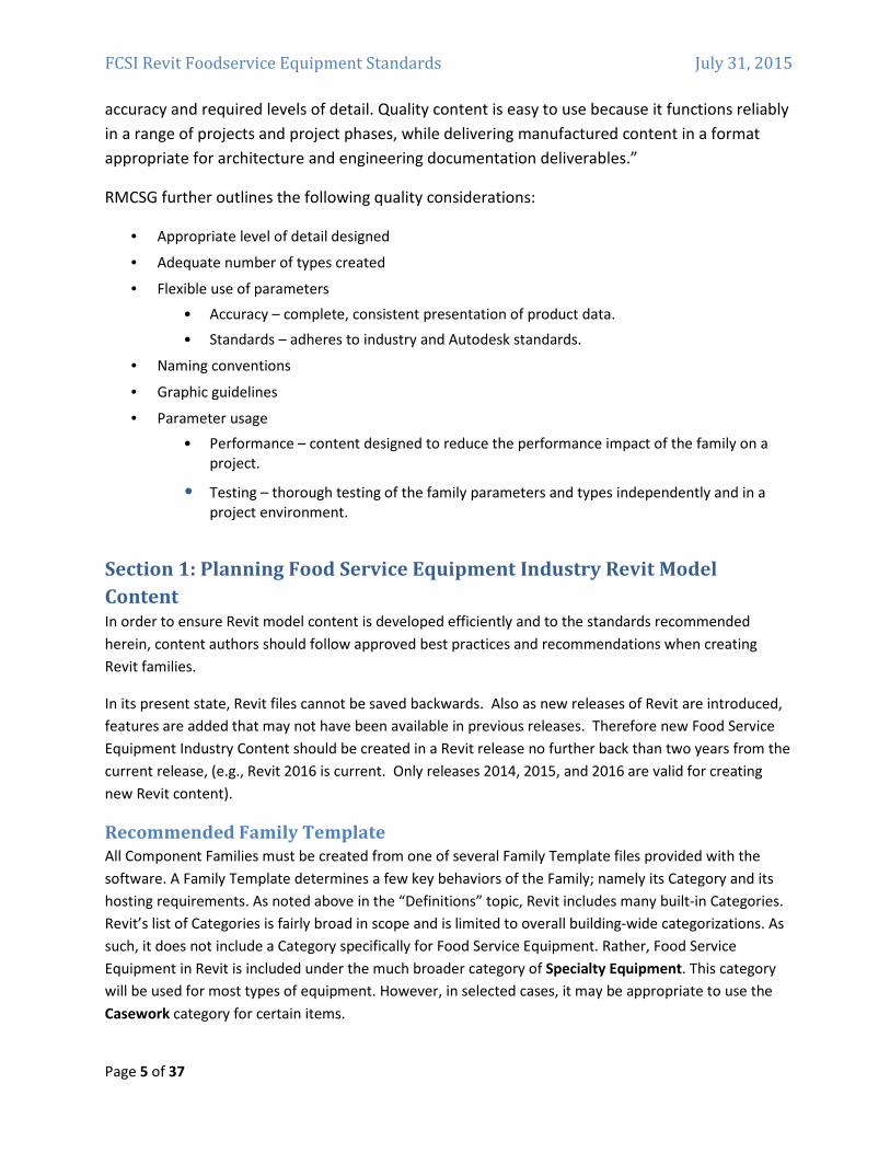
As a matter of best‐practice, please generate a simplified 2D version of the Family in plan view using
Symbolic lines. It is preferable to trace over all 3D forms with Symbolic Lines for the simplified 2D plan
representation, however you can include only those 3D forms which are low in polygon count (such as
simple rectilinear extrusions) in cases where the tracing of such forms would yield no benefit. Use the
visibility controls in Revit to turn off all complex 3D forms and other unnecessary details from the
simplified plan display.
Medium Level of Detail
Medium level of detail can be used in larger scale views and as the project progresses into the design
development phase. In Medium detail, you can begin to include details such as hinges, louvers,
clearances and latches. Many of these items can be added in plan and elevation views in the Family using
Symbolic lines to keep model size and complexity in check. In cases where you wish to avoid complex 3D
geometry, but still have details show in more than one view such as elevation and 3D views, consider
using Model Lines instead of solids and voids.
FCSI Revit Foodservice Equipment Standards July 31, 2015
Page 8 of 37
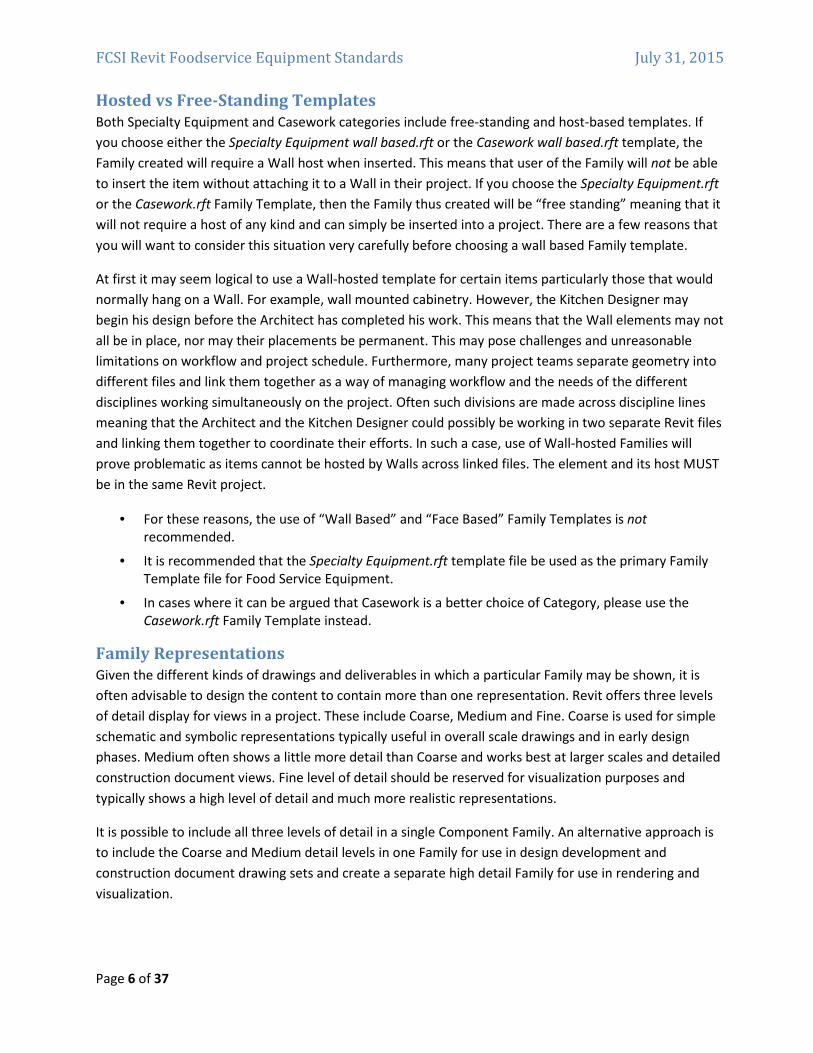
Limit the use of three‐dimensional geometry to overall forms that appear in multiple views like plans,
elevations and 3D. Symbolic lines used to represent the plan version of the Family for coarse scale should
continue to display here in medium wherever possible and be supplemented by additional 2D Symbolic
Lines as appropriate to represent further details required by medium detail. Use three‐dimensional
geometry for smaller details only when absolutely necessary or when it clearly adds an overall benefit to
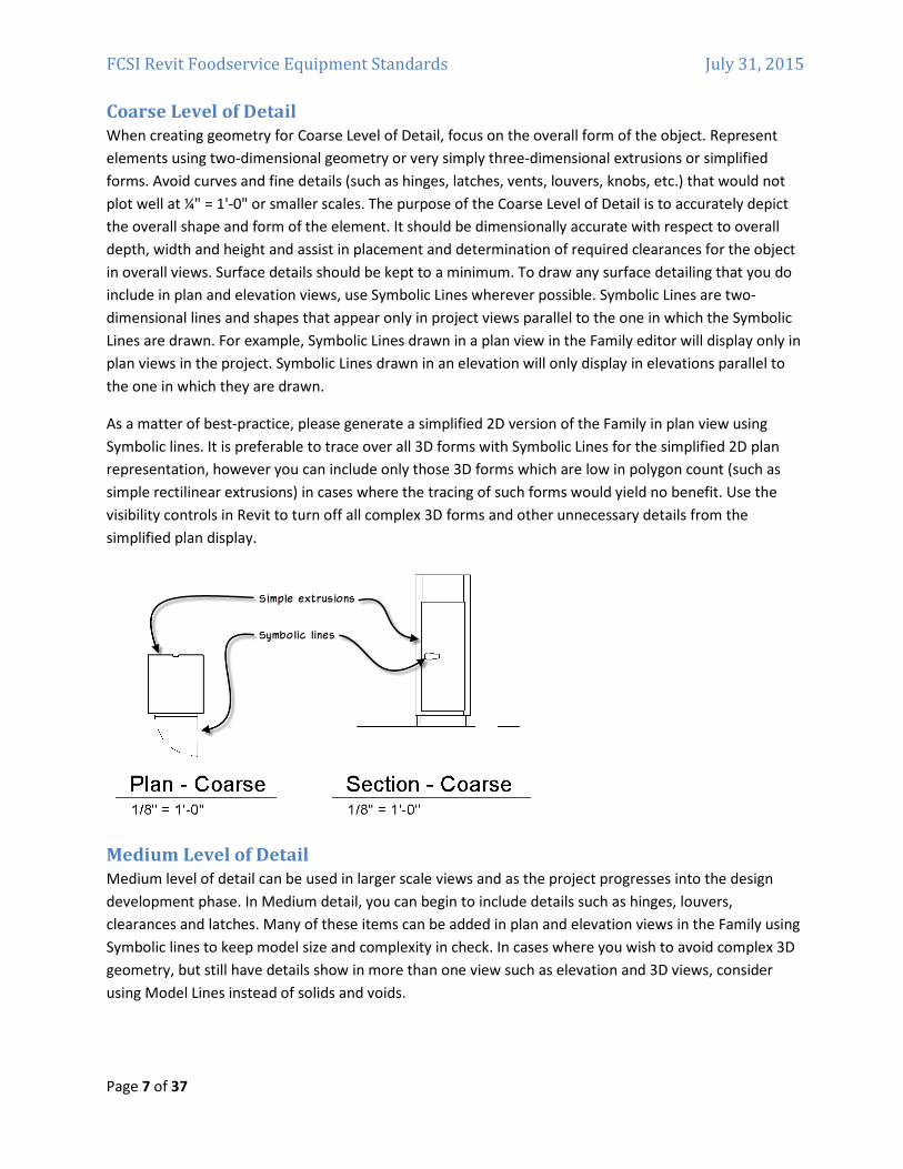
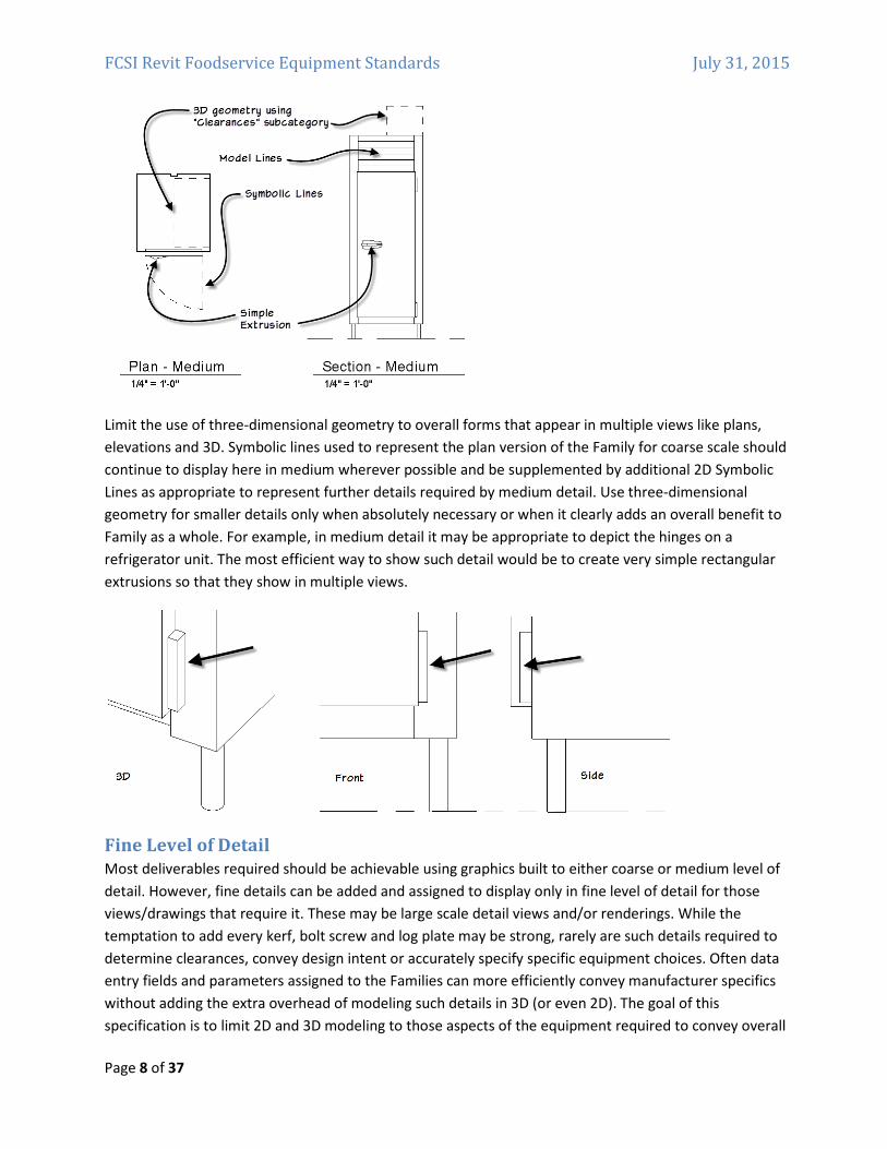
Family as a whole. For example, in medium detail it may be appropriate to depict the hinges on a
refrigerator unit. The most efficient way to show such detail would be to create very simple rectangular
extrusions so that they show in multiple views.
Fine Level of Detail
Most deliverables required should be achievable using graphics built to either coarse or medium level of
detail. However, fine details can be added and assigned to display only in fine level of detail for those
views/drawings that require it. These may be large scale detail views and/or renderings. While the
temptation to add every kerf, bolt screw and log plate may be strong, rarely are such details required to
determine clearances, convey design intent or accurately specify specific equipment choices. Often data
entry fields and parameters assigned to the Families can more efficiently convey manufacturer specifics
without adding the extra overhead of modeling such details in 3D (or even 2D). The goal of this
specification is to limit 2D and 3D modeling to those aspects of the equipment required to convey overall
FCSI Revit Foodservice Equipment Standards July 31, 2015
Page 9 of 37
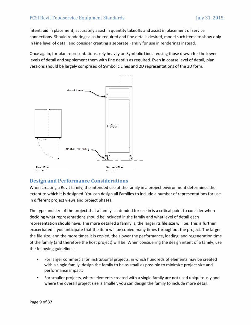
intent, aid in placement, accurately assist in quantity takeoffs and assist in placement of service
connections. Should renderings also be required and fine details desired, model such items to show only
in Fine level of detail and consider creating a separate Family for use in renderings instead.
Once again, for plan representations, rely heavily on Symbolic Lines reusing those drawn for the lower
levels of detail and supplement them with fine details as required. Even in coarse level of detail, plan
versions should be largely comprised of Symbolic Lines and 2D representations of the 3D form.
Design and Performance Considerations
When creating a Revit family, the intended use of the family in a project environment determines the
extent to which it is designed. You can design all Families to include a number of representations for use
in different project views and project phases.
The type and size of the project that a family is intended for use in is a critical point to consider when
deciding what representations should be included in the family and what level of detail each
representation should have. The more detailed a family is, the larger its file size will be. This is further
exacerbated if you anticipate that the item will be copied many times throughout the project. The larger
the file size, and the more times it is copied, the slower the performance, loading, and regeneration time
of the family (and therefore the host project) will be. When considering the design intent of a family, use
the following guidelines:
• For larger commercial or institutional projects, in which hundreds of elements may be created
with a single family, design the family to be as small as possible to minimize project size and
performance impact.
• For smaller projects, where elements created with a single family are not used ubiquitously and
where the overall project size is smaller, you can design the family to include more detail.
FCSI Revit Foodservice Equipment Standards July 31, 2015
Page 10 of 37
The key consideration to keep in mind when building food service equipment Families is to remember
that the impact of food service equipment Families can easily be masked by workflow of the typical
commercial kitchen designer. In other words, it would not be uncommon for a kitchen designer to work
in a separate Revit project file and link in only the architectural backgrounds as needed. Further, the
designer could easily isolate their efforts to a small and isolated area of the project or dedicated workset.
Doing so would offer many benefits to the kitchen designer allowing them to focus on the area of the
project within their realm of responsibility and increasing performance by avoiding the loading of the rest
of the project. For example, in a large commercial facility such as a complex medical or educational
facility, the areas requiring the services of a kitchen designer and needing to show food service
equipment may be quite limited. However, remember that even though you can isolate a small work area
and improve performance, ultimately all work areas must be brought back into a single model for
coordination efforts. Therefore, when building food service equipment, it is better to assume that most
projects requiring these items will be sizable enough to warrant the judicious modeling techniques
advocated in this document.
Family File Size Recommendations
The RMCSG includes a table recommending file sizes for many standard kinds of Families. Neither
Specialty equipment in general nor food service equipment in specific is included in the table. However,
based on the items that are included, the typical complexity required by food service items (as
recommended above) and standard best‐practice recommendations, a file size in the following ranges
are good recommendations:
• Simple 250K – 500K
• Complex 600K – 750K
When working on a Family file, you can compact the file to reduce its size. Choose Save As from the
Application menu and then click the Options button. Check the Compact checkbox and then click OK and
Save. In a project environment, Compact can also be used as can Purge Unused to reduce the size of the
project file.
As a further guideline, consider the following. A small food service project is likely to have 100 or fewer
items of heavy equipment, a medium one perhaps 100‐200, and a large project has over 200 items. At an
average of ½ MB per content item times 100 is a 50 megabyte file for the equipment only. If this
equipment is to be housed in the main architectural or MEP project file, this could have a significant
impact on overall project performance. It is therefore always beneficial to be as prudent with file sizes as
possible.
Level of Detail Strategies
When you build your Families, try to reuse elements as much as possible. In other words, build items that
will appear in fine level of detail and then use the visibility settings to hide them in lower levels of detail.
If necessary, draw a second version of the geometry for lower levels of detail. For example, when
drawing a piece of equipment with louver vents, consider the highest level of detail in which such louvers
should be modeled. If you can effectively represent such details using Model Lines instead of 3D
extrusions, this can be an effective way to manage file size and performance. If you instead must show a
FCSI Revit Foodservice Equipment Standards July 31, 2015
Page 11 of 37
three‐dimensional version of the louvers, show these only in fine level of detail and then show Model
Lines in the same location for the louvers in Medium detail. Try not to show them at all in coarse.
• Don’t model geometry that will not be visible when the family is added to a building model.
o For example, for a refrigerator or range, model the outside of the unit only. Model the
door, but not the inside of the range or refrigerator.
o If shelves or other items on the inside of the unit must be shown, depict them with
symbolic or model lines wherever possible in the views that would show them rather
than modeling such items.
o Do not include plates, kerfs, screws, or other highly specialized details.
• Do not duplicate geometry that can be used for different levels of detail. Use visibility settings
instead to control what is shown under each level of detail setting.
• The following guideline from the RMCSG can be helpful when modeling geometry:
If the geometry is… Set the detail level to…
Smaller than 1’ Fine
1’ – 3’ Medium
Larger than 3’ Coarse
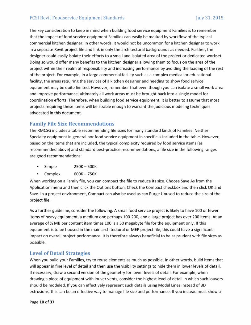
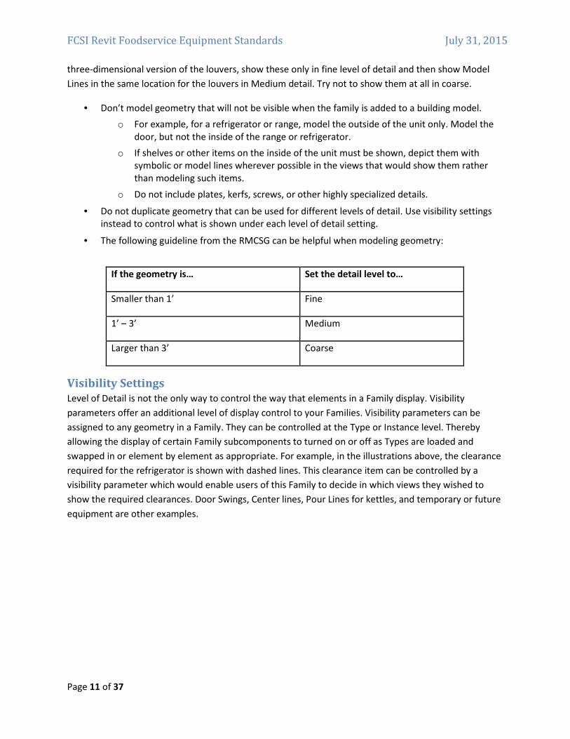
Visibility Settings
Level of Detail is not the only way to control the way that elements in a Family display. Visibility
parameters offer an additional level of display control to your Families. Visibility parameters can be
assigned to any geometry in a Family. They can be controlled at the Type or Instance level. Thereby
allowing the display of certain Family subcomponents to turned on or off as Types are loaded and
swapped in or element by element as appropriate. For example, in the illustrations above, the clearance
required for the refrigerator is shown with dashed lines. This clearance item can be controlled by a
visibility parameter which would enable users of this Family to decide in which views they wished to
show the required clearances. Door Swings, Center lines, Pour Lines for kettles, and temporary or future
equipment are other examples.
FCSI Revit Foodservice Equipment Standards July 31, 2015
Page 12 of 37
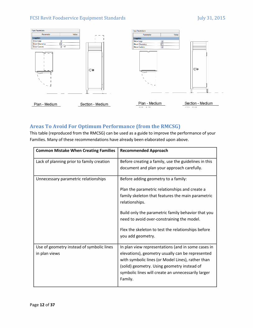
Areas To Avoid For Optimum Performance (from the RMCSG)
This table (reproduced from the RMCSG) can be used as a guide to improve the performance of your
Families. Many of these recommendations have already been elaborated upon above.
Common Mistake When Creating Families Recommended Approach
Lack of planning prior to family creation Before creating a family, use the guidelines in this
document and plan your approach carefully.
Unnecessary parametric relationships Before adding geometry to a family:
Plan the parametric relationships and create a
family skeleton that features the main parametric
relationships.
Build only the parametric family behavior that you
need to avoid over‐constraining the model.
Flex the skeleton to test the relationships before
you add geometry.
Use of geometry instead of symbolic lines
in plan views
In plan view representations (and in some cases in
elevations), geometry usually can be represented
with symbolic lines (or Model Lines), rather than
(solid) geometry. Using geometry instead of
symbolic lines will create an unnecessarily larger
Family.
FCSI Revit Foodservice Equipment Standards July 31, 2015
Page 13 of 37
High levels of geometric detail and
underuse of visibility settings
Use the guidelines in the topics above to avoid
unnecessarily large Family files.
Overuse of voids, formulas, and arrays Extensive use of voids, formulas, and arrays will
add to the overall Family size and affect its
performance in projects.
Use of too many nested Families (Families
imported into other Families)
Nest Families to create geometry in other Families
strategically. Use nested content to share objects
among multiple Families, for example, door
hardware, burner configurations, and so on.
Large Families with many Types that do
not include Type catalogs
The more Types (particularly unused) the heavier
the Family. Create Type catalogs for Families that
contain 6 or more Types.
Inadequate Family testing See 3.1General Family Testing Guidelines.
The purpose of creating Revit families for manufactured content is not for the manufacturing process,
but for architecture and engineering documentation deliverables. It is important to create the family
content at an appropriate level of detail for the intended use. In order to be considered in compliance
with this standard, it is required that all geometry be modeled directly in Revit using native Revit tools.
Elements can be created from imported geometry, but such imported geometry should be removed from
the final content item before distribution. Furthermore every attempt should be made to build native
geometry using the guidelines detailed herein.
Nested Families, Groups and Voids
Nested Families are Families that are inserted as components within other Families. Nesting one Family
within another can have many benefits. For example, if the same item must appear in more than one
Family, like a common door handle, range burner configuration or refrigerator door. By creating the item
as a separate Family and then nesting it into other Families, you can reuse items in a logical way. Another
important advantage can arise when adding parameters to a nested Family instance. Consider a common
element such as refrigerator door or range burner configuration. If you copy and paste the actual
geometry from one Family to another, you must take greater care when establishing your reference
planes and overall framework to be certain that the Family and the burners flexes the way you expect. If
the burners are a nested Family, it can be easier to establish the desired relationship and achieve the
correct flexing behavior with fewer constraints and parameters.
However, just as nesting Families in a logical way can have enormous benefits, nesting them too many
levels deep can cause performance and other problems. Try to plan your strategy with respect to nesting
carefully and limit nesting to no more than two levels deep. Remember, when you load a Family into a
FCSI Revit Foodservice Equipment Standards July 31, 2015
Page 14 of 37
project, it also loads all of the nested Families. If one of the nested Families should be updated, it updates
across the project in all locations that it is used including the nested instances.
Groups and Voids can also be quite useful in a Family when used sparingly but also impose performance
penalties when overused or used improperly. For example, parametric arrays can be very compelling and
useful. However, when used extensively in a Family, they can exact a huge price in performance.
Furthermore, even when used sparingly in a single Family, if that Family is copied many times in a project,
performance can still take a hit. Therefore, limit array Groups in Families to those situations where the
quantity of items must be parametric. If you can use other means to give the same degree of choice to
the end user however, you may wish to entertain such alternatives in lieu of parametric arrays. For
example, if a range has 4 burners or 6 burners, it might make more sense to use a simple set of visibility
parameters to give the user a choice between the two rather than a parametric and grouped array.
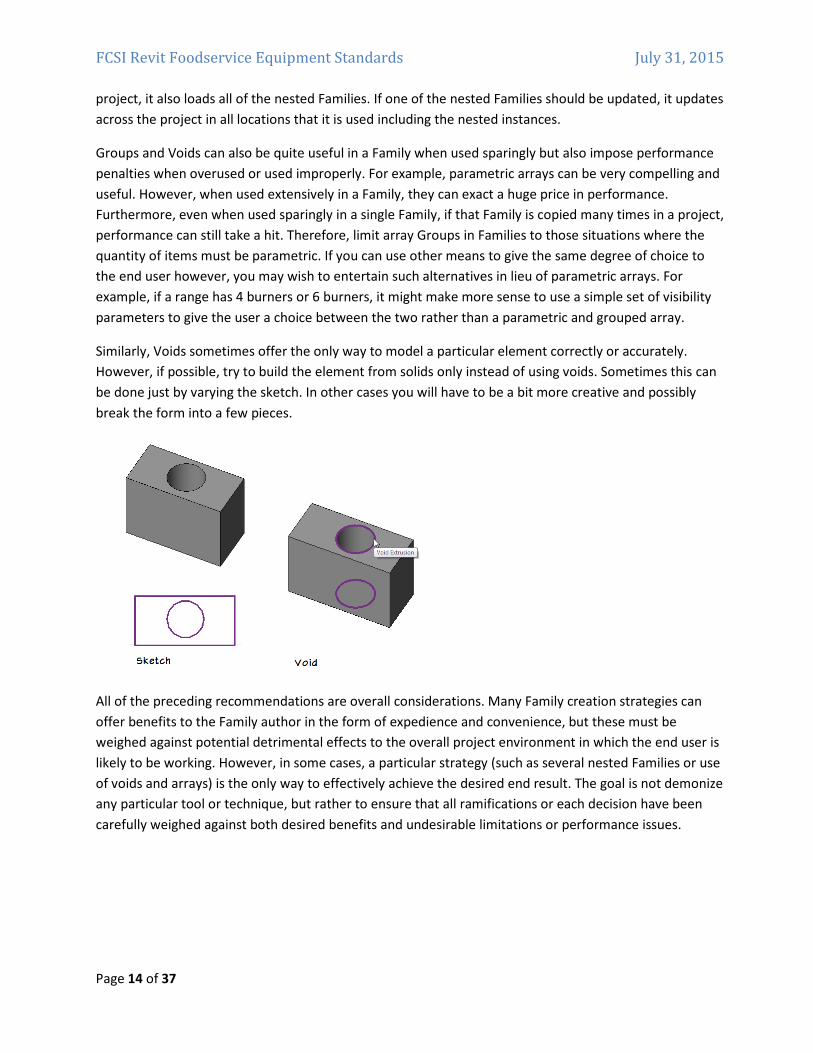
Similarly, Voids sometimes offer the only way to model a particular element correctly or accurately.
However, if possible, try to build the element from solids only instead of using voids. Sometimes this can
be done just by varying the sketch. In other cases you will have to be a bit more creative and possibly
break the form into a few pieces.
All of the preceding recommendations are overall considerations. Many Family creation strategies can
offer benefits to the Family author in the form of expedience and convenience, but these must be
weighed against potential detrimental effects to the overall project environment in which the end user is
likely to be working. However, in some cases, a particular strategy (such as several nested Families or use
of voids and arrays) is the only way to effectively achieve the desired end result. The goal is not demonize
any particular tool or technique, but rather to ensure that all ramifications or each decision have been
carefully weighed against both desired benefits and undesirable limitations or performance issues.
FCSI Revit Foodservice Equipment Standards July 31, 2015
Page 15 of 37
Using Imported Geometry
Revit families support the import of content created in the following CAD file formats:
• DWG (Autodesk AutoCAD format)
• DXF (AutoCAD Drawing Interchange Format)
• SAT (Spatial Corporation Standard ACIS format)
• SKP (Google SketchUp Model format)
• ADSK (Autodesk AEC Exchange environment – Inventor to Revit)
The ADSK format is a new format introduced by Autodesk in recent releases of Inventor and Revit for the
purposes of bridging between content items designed in Inventor (in high levels of manufacturing level
detail) and Revit which requires a “specification” level of detail. You can learn more about the ADSK file
format and strategies to utilize it in your Revit content in the RMCSG.
The other file formats can be imported directly into a Revit Family. If you import content into a family and
use it to create the family without modification, the resulting family types will be added to building
models as static elements that do not support the dynamic parametric relationships inherent in Revit
building models. Families created directly from imported content do not support direct assignment of
materials and other parameters, limiting their overall use in the project environment. Imported content
may also have adverse effects on project performance. In some cases, these limitations may be
acceptable, but to conform to standard building information modeling practice, it is recommended that
most imported content should be recreated as a fully functional Revit family.
In most cases, it is considered best‐practice to import the geometry into a new Revit Family template,
position it in the desired location and then create new native Revit geometry in its place. When this
process is complete, you can delete the imported CAD file to help reduce file size and undesired artifacts
from the new Family file.
Using Manufacturer Logos
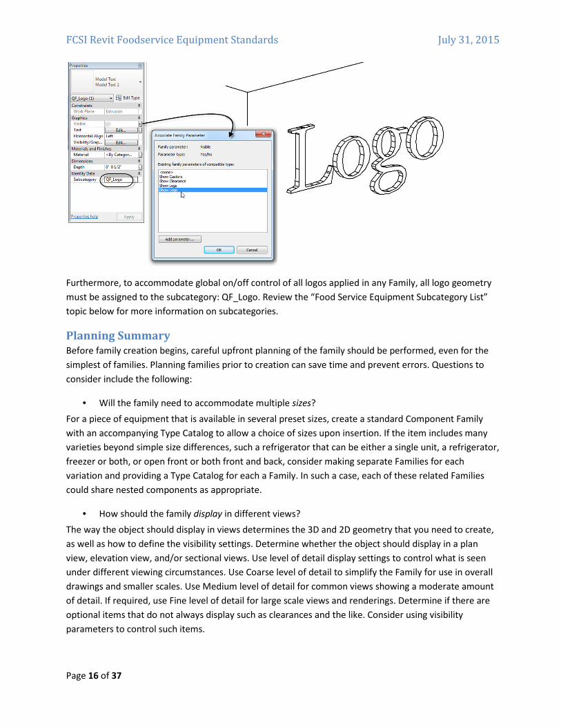
Logos or other manufacturer specific identification is permitted in the geometry of your Family file
provided that such identifiers are controlled by a Revit visibility parameter. The parameter should be
named: Show Logo and configured as a Yes/No parameter. Any geometry in the Family that represents
logo or manufacturer’s identification should have this Yes/No parameter assigned to control its visible
parameter in the Family Editor.
FCSI Revit Foodservice Equipment Standards July 31, 2015
Page 16 of 37
Furthermore, to accommodate global on/off control of all logos applied in any Family, all logo geometry
must be assigned to the subcategory: QF_Logo. Review the “Food Service Equipment Subcategory List”
topic below for more information on subcategories.
Planning Summary
Before family creation begins, careful upfront planning of the family should be performed, even for the
simplest of families. Planning families prior to creation can save time and prevent errors. Questions to
consider include the following:
• Will the family need to accommodate multiple sizes?
For a piece of equipment that is available in several preset sizes, create a standard Component Family
with an accompanying Type Catalog to allow a choice of sizes upon insertion. If the item includes many
varieties beyond simple size differences, such a refrigerator that can be either a single unit, a refrigerator,
freezer or both, or open front or both front and back, consider making separate Families for each
variation and providing a Type Catalog for each a Family. In such a case, each of these related Families
could share nested components as appropriate.
• How should the family display in different views?
The way the object should display in views determines the 3D and 2D geometry that you need to create,
as well as how to define the visibility settings. Determine whether the object should display in a plan
view, elevation view, and/or sectional views. Use level of detail display settings to control what is seen
under different viewing circumstances. Use Coarse level of detail to simplify the Family for use in overall
drawings and smaller scales. Use Medium level of detail for common views showing a moderate amount
of detail. If required, use Fine level of detail for large scale views and renderings. Determine if there are
optional items that do not always display such as clearances and the like. Consider using visibility
parameters to control such items.
FCSI Revit Foodservice Equipment Standards July 31, 2015
Page 17 of 37
• Does this family require a host?
While several food service items could potentially benefit from using a Wall or Floor host, it is
recommended that to ensure the greatest level of flexibility and compatibility with the files and
workflows of the other players in the industry who may use your content that you refrain from using
hosted Families. Build all food service equipment using either the Specialty Equipment.rft or the
Casework.rft Family Template.
• How much detail should be modeled?
In some cases, you may not need 3D geometry. You may only need to sketch a 2D shape to represent
your Family. Also, you may simplify the 3D geometry of your model to save time in creating the Family.
For example, common elements like burners, louvers, handles and hinges do not require much detail to
be recognizable. Model only what is necessary to convey intent and understanding of an element’s
function.
• What is the insertion/origin point of this family?
The insertion/origin point is the point at which you want to place the family in a project (indicated by the
cursor position). Determining the appropriate insertion point will help users place the family in a project.
Often Families will use the geometric center. This in no way limits the ultimate placement of the Family,
but rather makes flexing the dimensions easier. You can include Reference Planes in the Family to assist
in placement in projects. Such Reference Planes can even be used to indicate that a Family should have a
certain clearance to a nearby wall or other item. Typically the insertion point for a Foodservice
Equipment Symbol has been the left rear corner as the operator faces the item. If Clearance Lines are
needed, they are offset the correct distance from this location.
Section 2: Food Service Equipment Industry Model Content Creation
Standards The topics in this section detail standards for creation of Food Service Equipment Industry Revit Family
content that is in compliance with industry accepted best practices and published Autodesk standards.
Before you create a model family, review the standards in this section, and then use the best practice
workflow below to create your content. This workflow helps to ensure that your content is created in the
most efficient and least error‐prone manner.
Family Creation Process
The basic steps for creating a Component Family include the following:
1. Create a new family file (RFA) using either the Specialty Equipment.rft or the Casework.rft Family
Template.
2. Define subcategories for the family to help control the visibility of the family geometry.
3. Create the family skeleton, or framework:
a. Define the origin (the insertion point) of the family.
FCSI Revit Foodservice Equipment Standards July 31, 2015
Page 18 of 37
b. Lay out reference planes to snap to when you sketch component geometry.
c. Add dimensions to specify parametric relationships.
d. Label dimensions to create type or instance parameters.
e. Test, or flex, the skeleton.
4. Define family type variations by specifying different parameters.
5. Add a single level of geometry in solids and voids, and constrain the geometry to reference
planes.
6. Flex the new model (types and hosts) to verify correct component behavior.
7. Repeat previous steps until the family geometry is complete.
8. Specify 2D and 3D geometry display characteristics with subcategory and entity visibility settings.
9. Save the family, and then test it in a project.
10. For Families requiring more than six Types, create a Type Catalog.
The above summary is included in the RMCSG. The steps are standard industry‐wide best practice. Many
resources are available to learn more about building Families. Search the Autodesk website, the online
help and one of the many blogs and user forums for many articles and tutorials on the subject. Books and
other resources are also available detailing every aspect of using Revit and Family content creation.
Prototyping
If you need to create a number of similar families:
1. Plan and create a single “prototype” Family.
2. Test the prototype Family in the Family Editor and in a project environment to identify any errors
or inconsistencies.
3. Correct any errors and inconsistencies and retest the Family to ensure it is works properly before
creating the additional Families based on the prototype.
Units
Although families can be created as unit‐specific (imperial or metric), Revit software stores all
coordinates in universal units and displays specific units according to user preference. This means that:
• Units can be set to display as necessary for a target audience (i.e., display as decimal units for a
civil engineering drawing or fractional units for an architectural drawing).
• Families created in imperial units may be loaded into and used in metric projects and vice versa.
For information on changing the display of units, see “Project Units” in the Revit Help.
If unit‐specific names are used in the Family or Type name, these will still appear when used in files of the
other unit type. To avoid this, either refrain from using unit‐specific names or rename Families or Types
accordingly.
Recommendation: If you need to create content for both Imperial and Metric audiences, create unique
Type Catalogs for each locale.
FCSI Revit Foodservice Equipment Standards July 31, 2015
Page 19 of 37
Family Naming Guidelines
Resource naming is at the heart of any standard. It is important to name shared elements in a consistent
and logical fashion so that they may be used by individuals in different organizations with little or no
advance knowledge or translation required. Family and Type naming in Revit are certainly no exception.
Family names are the primary means of identifying families in the Revit software.
After experimenting with other naming conventions, we recommend the following standards for naming
Revit families of Foodservice Equipment:
• Create unique names for each Family.
• To identify foodservice equipment in the Specialty Equipment Category, all Families are to be
identified by the prefix QF_.
• The Family name should include the Manufacturer’s name and the equipment item model
number. For consistency in matching Revit projects to database utilities, we recommend using
the name and model number as represented in AutoQuotes.
• Do not include the Family category in the Family name.
• Use ‘title casing’ (as with the title of a book) for Family names, as they are case sensitive.
• Keep file names as short as possible. Family names must display in dialogs and in the Type
Selector list in Revit.
• Do not use spaces between words in file names. To separate words within a syntax element (e.g.,
Manufacturer or Model Number) use the underscore character (_).
• A Type Catalog and its associated Family should be identified by including _cat before the file
name extension. If a series of model numbers is covered by a Type Catalog, the model numbers
may appear in the name.
• If a Type Catalog is to be used with a Family, name the Type Catalog (TXT file) with the same
name as the Family. This is required for Revit to recognize the Type Catalog.
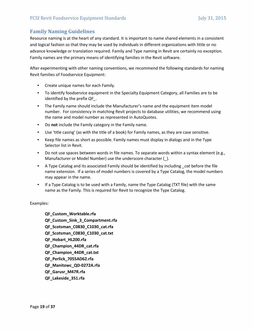
Examples:
QF_Custom_Worktable.rfa
QF_Custom_Sink_3_Compartment.rfa
QF_Scotsman_C0830_C1030_cat.rfa
QF_Scotsman_C0830_C1030_cat.txt
QF_Hobart_HL200.rfa
QF_Champion_44DR_cat.rfa
QF_Champion_44DR_cat.txt
QF_Perlick_7055AD62.rfa
QF_Manitowc_QD-0272A.rfa
QF_Garusr_M47R.rfa
QF_Lakeside_351.rfa
FCSI Revit Foodservice Equipment Standards July 31, 2015
Page 20 of 37
Family Type Naming Guidelines
When naming a family Type, use the format and rules below:
• Do not include the Family name or category in the Type name.
• Type names should mirror actual usage. Type names may include model numbers.
• Type names should indicate the key differences between Types (configuration, utilities, size, etc.)
and, when applicable, reflect standard sizes. In some cases, you may base names on size
difference, but use common terms rather than numbers.
• When Types are named by size, use dimensions only. Avoid the use of characters or words. (h, w,
d, or height, width, depth).
• Type names should include units or capacity and a unit indicator, unless they represent nominal
sizes.
• Keep Type names as short as possible. Type names must display in dialogs and in the Type
Selector.
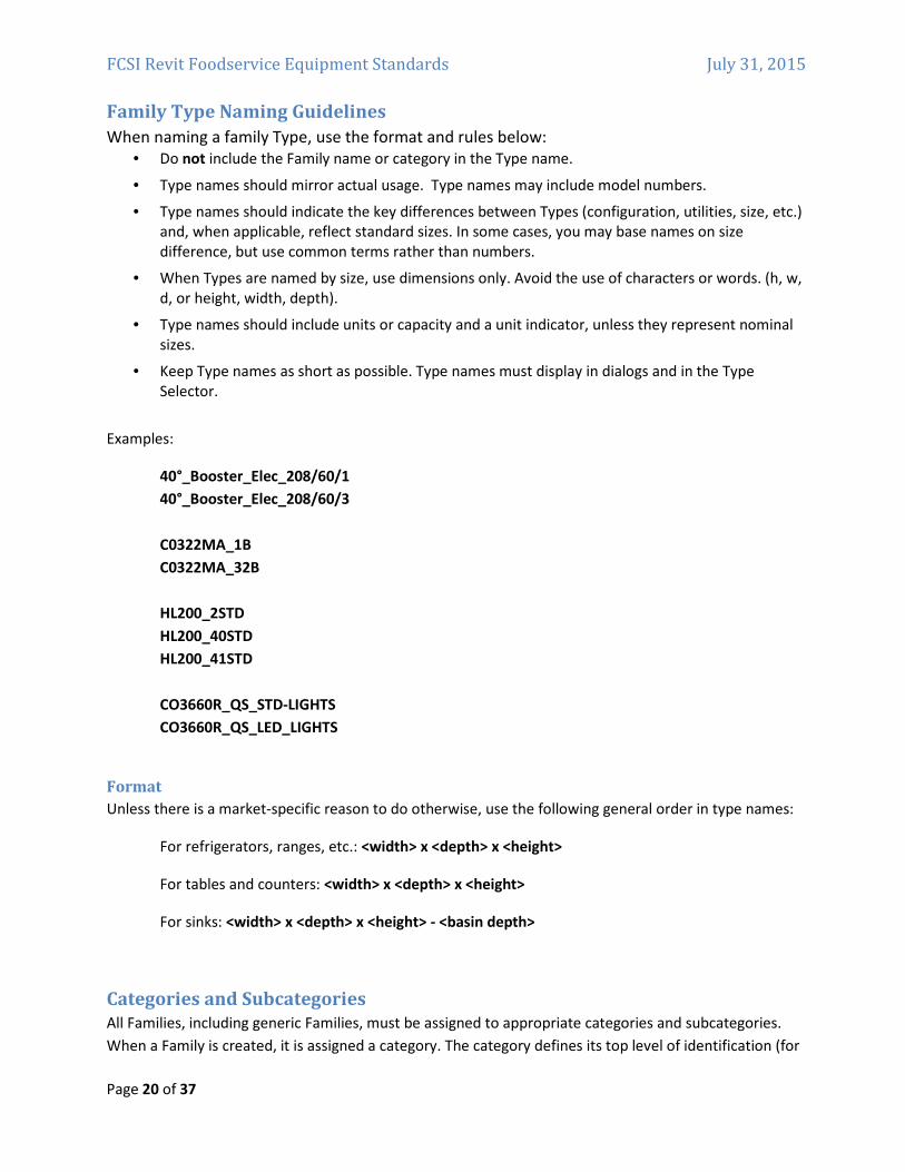
Examples:
40°_Booster_Elec_208/60/1
40°_Booster_Elec_208/60/3
C0322MA_1B
C0322MA_32B
HL200_2STD
HL200_40STD
HL200_41STD
CO3660R_QS_STD-LIGHTS
CO3660R_QS_LED_LIGHTS
Format
Unless there is a market‐specific reason to do otherwise, use the following general order in type names:
For refrigerators, ranges, etc.: <width> x <depth> x <height>
For tables and counters: <width> x <depth> x <height>
For sinks: <width> x <depth> x <height> - <basin depth>
Categories and Subcategories
All Families, including generic Families, must be assigned to appropriate categories and subcategories.
When a Family is created, it is assigned a category. The category defines its top level of identification (for
FCSI Revit Foodservice Equipment Standards July 31, 2015
Page 21 of 37
example, Specialty Equipment or Casework) within the project environment. When the Family is used in a
project, the Family can be located in the Project Browser under its category, and elements created by the
Family Types will schedule by its category. The line weight, line color, line pattern, and material
assignment of the Family geometry can also be assigned to by category.
To display different line weights, line colors, line patterns, and material assignments for different
geometric components of the Family (for example, Undercounter Details, Overcounter Details or Surface
Details), the components can be assigned to subcategories within the Family category.
Categories are predefined in Revit software and cannot be created or changed by the user. Subcategories
are predefined in some Families, but other subcategories can be created in Families as needed.
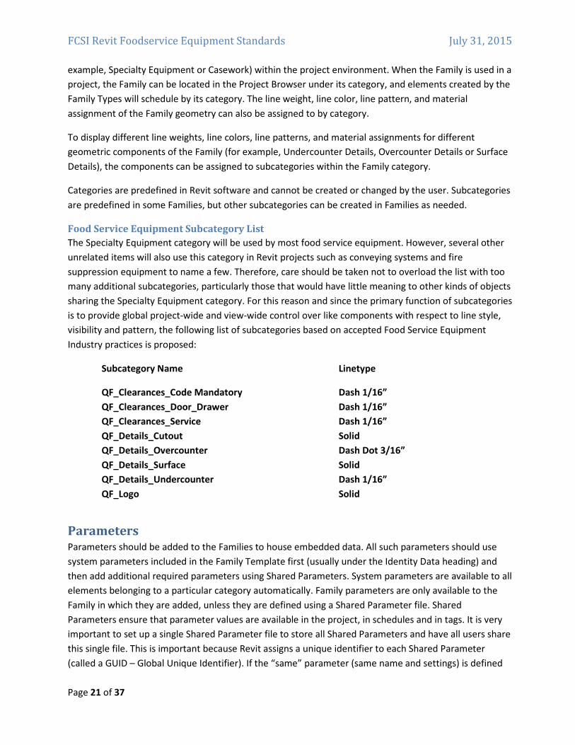
Food Service Equipment Subcategory List
The Specialty Equipment category will be used by most food service equipment. However, several other
unrelated items will also use this category in Revit projects such as conveying systems and fire
suppression equipment to name a few. Therefore, care should be taken not to overload the list with too
many additional subcategories, particularly those that would have little meaning to other kinds of objects
sharing the Specialty Equipment category. For this reason and since the primary function of subcategories
is to provide global project‐wide and view‐wide control over like components with respect to line style,
visibility and pattern, the following list of subcategories based on accepted Food Service Equipment
Industry practices is proposed:
Subcategory Name Linetype
QF_Clearances_Code Mandatory Dash 1/16”
QF_Clearances_Door_Drawer Dash 1/16”
QF_Clearances_Service Dash 1/16”
QF_Details_Cutout Solid
QF_Details_Overcounter Dash Dot 3/16”
QF_Details_Surface Solid
QF_Details_Undercounter Dash 1/16”
QF_Logo Solid
Parameters Parameters should be added to the Families to house embedded data. All such parameters should use
system parameters included in the Family Template first (usually under the Identity Data heading) and
then add additional required parameters using Shared Parameters. System parameters are available to all
elements belonging to a particular category automatically. Family parameters are only available to the
Family in which they are added, unless they are defined using a Shared Parameter file. Shared
Parameters ensure that parameter values are available in the project, in schedules and in tags. It is very
important to set up a single Shared Parameter file to store all Shared Parameters and have all users share
this single file. This is important because Revit assigns a unique identifier to each Shared Parameter
(called a GUID – Global Unique Identifier). If the “same” parameter (same name and settings) is defined
FCSI Revit Foodservice Equipment Standards July 31, 2015
Page 22 of 37
by two different individuals in separate Shared Parameter files, Revit will NOT see them as the same!
Each version of the parameter would still have a different GUID making Revit see the two parameters as
different.
This situation presents some unique challenges to the effort to standardize content and parameters
across the many food service equipment manufacturers creating content for the industry. For this reason,
a recommended Shared Parameter file containing a list of all food service parameters anticipated has
been included with this document. There are utilities online that can be used to merge such a file with
any existing Shared Parameter files that may already be in use in the end‐user’s firm. Given the
importance of maintaining the integrity of the Shared Parameter file across your organization, you are
highly encouraged to utilize such a tool to or other acceptable means to ensure that all required Shared
Parameters are defined properly and in a single Shared Parameter file.
REQUIREMENT: To promote consistency in model content (particularly for manufacturer content that is
shared on Autodesk Seek), use parameters as they are explicitly defined (including the GUID) in the
approved shared parameters file. If a required parameter is not in the file, add it to your content as
necessary. It is also recommended to include the shared parameter file containing the additional
parameters with your content package. When creating custom parameters, follow the naming
conventions included herein.
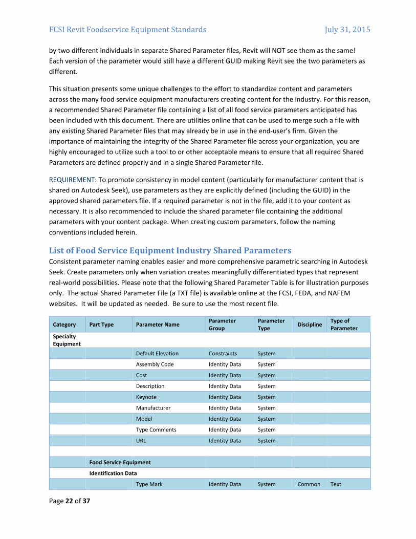
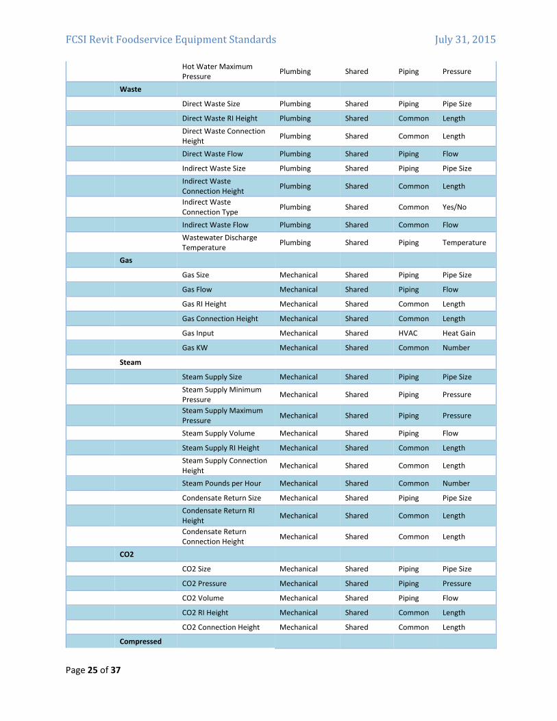
List of Food Service Equipment Industry Shared Parameters
Consistent parameter naming enables easier and more comprehensive parametric searching in Autodesk
Seek. Create parameters only when variation creates meaningfully differentiated types that represent
real‐world possibilities. Please note that the following Shared Parameter Table is for illustration purposes
only. The actual Shared Parameter File (a TXT file) is available online at the FCSI, FEDA, and NAFEM
websites. It will be updated as needed. Be sure to use the most recent file.
Category Part Type Parameter Name Parameter
Group
Parameter
Type Discipline
Type of
Parameter
Specialty
Equipment
Default Elevation Constraints System
Assembly Code Identity Data System
Cost Identity Data System
Description Identity Data System
Keynote Identity Data System
Manufacturer Identity Data System
Model Identity Data System
Type Comments Identity Data System
URL Identity Data System
Food Service Equipment
Identification Data
Type Mark Identity Data System Common Text
FCSI Revit Foodservice Equipment Standards July 31, 2015
Page 23 of 37
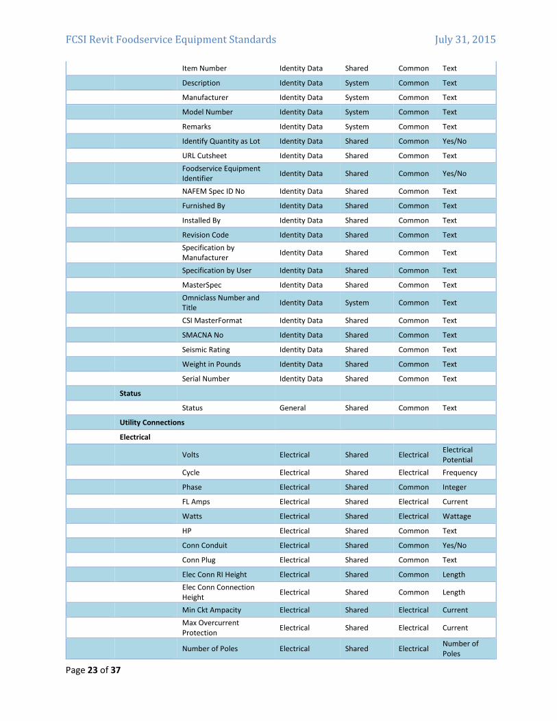
Item Number Identity Data Shared Common Text
Description Identity Data System Common Text
Manufacturer Identity Data System Common Text
Model Number Identity Data System Common Text
Remarks Identity Data System Common Text
Identify Quantity as Lot Identity Data Shared Common Yes/No
URL Cutsheet Identity Data Shared Common Text
Foodservice Equipment
Identifier Identity Data Shared Common Yes/No
NAFEM Spec ID No Identity Data Shared Common Text
Furnished By Identity Data Shared Common Text
Installed By Identity Data Shared Common Text
Revision Code Identity Data Shared Common Text
Specification by
Manufacturer Identity Data Shared Common Text
Specification by User Identity Data Shared Common Text
MasterSpec Identity Data Shared Common Text
Omniclass Number and
Title Identity Data System Common Text
CSI MasterFormat Identity Data Shared Common Text
SMACNA No Identity Data Shared Common Text
Seismic Rating Identity Data Shared Common Text
Weight in Pounds Identity Data Shared Common Text
Serial Number Identity Data Shared Common Text
Status
Status General Shared Common Text
Utility Connections
Electrical
Volts Electrical Shared Electrical
Electrical
Potential
Cycle Electrical Shared Electrical Frequency
Phase Electrical Shared Common Integer
FL Amps Electrical Shared Electrical Current
Watts Electrical Shared Electrical Wattage
HP Electrical Shared Common Text
Conn Conduit Electrical Shared Common Yes/No
Conn Plug Electrical Shared Common Text
Elec Conn RI Height Electrical Shared Common Length
Elec Conn Connection
Height Electrical Shared Common Length
Min Ckt Ampacity Electrical Shared Electrical Current
Max Overcurrent
Protection Electrical Shared Electrical Current
Number of Poles Electrical Shared Electrical
Number of
Poles
FCSI Revit Foodservice Equipment Standards July 31, 2015
Page 24 of 37
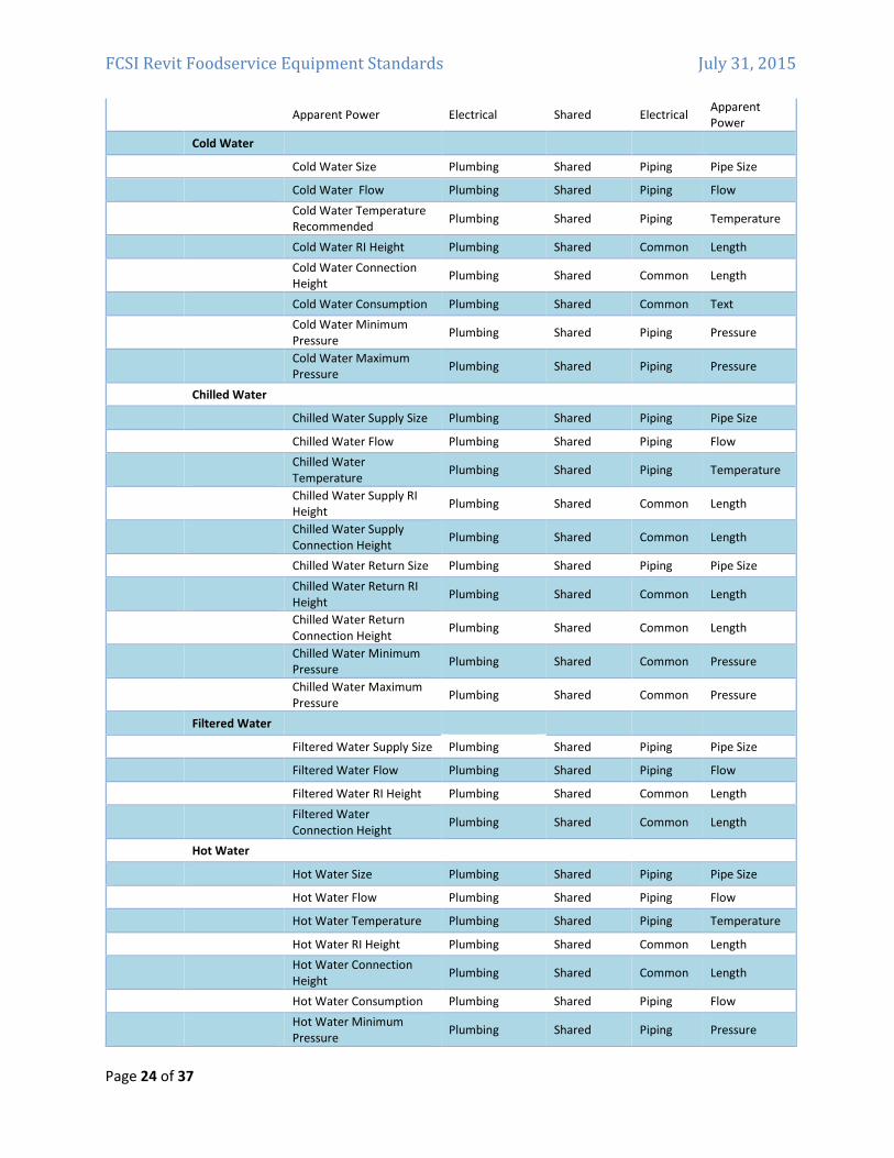
Apparent Power Electrical Shared Electrical
Apparent
Power
Cold Water
Cold Water Size Plumbing Shared Piping Pipe Size
Cold Water Flow Plumbing Shared Piping Flow
Cold Water Temperature
Recommended Plumbing Shared Piping Temperature
Cold Water RI Height Plumbing Shared Common Length
Cold Water Connection
Height Plumbing Shared Common Length
Cold Water Consumption Plumbing Shared Common Text
Cold Water Minimum
Pressure Plumbing Shared Piping Pressure
Cold Water Maximum
Pressure Plumbing Shared Piping Pressure
Chilled Water
Chilled Water Supply Size Plumbing Shared Piping Pipe Size
Chilled Water Flow Plumbing Shared Piping Flow
Chilled Water
Temperature Plumbing Shared Piping Temperature
Chilled Water Supply RI
Height Plumbing Shared Common Length
Chilled Water Supply
Connection Height Plumbing Shared Common Length
Chilled Water Return Size Plumbing Shared Piping Pipe Size
Chilled Water Return RI
Height Plumbing Shared Common Length
Chilled Water Return
Connection Height Plumbing Shared Common Length
Chilled Water Minimum
Pressure Plumbing Shared Common Pressure
Chilled Water Maximum
Pressure Plumbing Shared Common Pressure
Filtered Water
Filtered Water Supply Size Plumbing Shared Piping Pipe Size
Filtered Water Flow Plumbing Shared Piping Flow
Filtered Water RI Height Plumbing Shared Common Length
Filtered Water
Connection Height Plumbing Shared Common Length
Hot Water
Hot Water Size Plumbing Shared Piping Pipe Size
Hot Water Flow Plumbing Shared Piping Flow
Hot Water Temperature Plumbing Shared Piping Temperature
Hot Water RI Height Plumbing Shared Common Length
Hot Water Connection
Height Plumbing Shared Common Length
Hot Water Consumption Plumbing Shared Piping Flow
Hot Water Minimum
Pressure Plumbing Shared Piping Pressure
FCSI Revit Foodservice Equipment Standards July 31, 2015
Page 25 of 37
Hot Water Maximum
Pressure Plumbing Shared Piping Pressure
Waste
Direct Waste Size Plumbing Shared Piping Pipe Size
Direct Waste RI Height Plumbing Shared Common Length
Direct Waste Connection
Height Plumbing Shared Common Length
Direct Waste Flow Plumbing Shared Piping Flow
Indirect Waste Size Plumbing Shared Piping Pipe Size
Indirect Waste
Connection Height Plumbing Shared Common Length
Indirect Waste
Connection Type Plumbing Shared Common Yes/No
Indirect Waste Flow Plumbing Shared Common Flow
Wastewater Discharge
Temperature Plumbing Shared Piping Temperature
Gas
Gas Size Mechanical Shared Piping Pipe Size
Gas Flow Mechanical Shared Piping Flow
Gas RI Height Mechanical Shared Common Length
Gas Connection Height Mechanical Shared Common Length
Gas Input Mechanical Shared HVAC Heat Gain
Gas KW Mechanical Shared Common Number
Steam
Steam Supply Size Mechanical Shared Piping Pipe Size
Steam Supply Minimum
Pressure Mechanical Shared Piping Pressure
Steam Supply Maximum
Pressure Mechanical Shared Piping Pressure
Steam Supply Volume Mechanical Shared Piping Flow
Steam Supply RI Height Mechanical Shared Common Length
Steam Supply Connection
Height Mechanical Shared Common Length
Steam Pounds per Hour Mechanical Shared Common Number
Condensate Return Size Mechanical Shared Piping Pipe Size
Condensate Return RI
Height Mechanical Shared Common Length
Condensate Return
Connection Height Mechanical Shared Common Length
CO2
CO2 Size Mechanical Shared Piping Pipe Size
CO2 Pressure Mechanical Shared Piping Pressure
CO2 Volume Mechanical Shared Piping Flow
CO2 RI Height Mechanical Shared Common Length
CO2 Connection Height Mechanical Shared Common Length
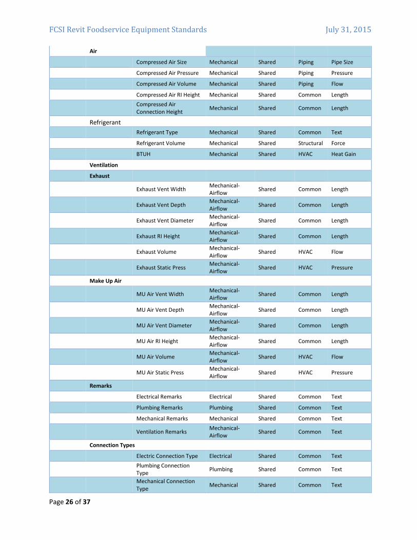
Compressed
FCSI Revit Foodservice Equipment Standards July 31, 2015
Page 26 of 37
Air
Compressed Air Size Mechanical Shared Piping Pipe Size
Compressed Air Pressure Mechanical Shared Piping Pressure
Compressed Air Volume Mechanical Shared Piping Flow
Compressed Air RI Height Mechanical Shared Common Length
Compressed Air
Connection Height Mechanical Shared Common Length
Refrigerant
Refrigerant Type Mechanical Shared Common Text
Refrigerant Volume Mechanical Shared Structural Force
BTUH Mechanical Shared HVAC Heat Gain
Ventilation
Exhaust
Exhaust Vent Width
Mechanical‐
Airflow Shared Common Length
Exhaust Vent Depth
Mechanical‐
Airflow Shared Common Length
Exhaust Vent Diameter
Mechanical‐
Airflow Shared Common Length
Exhaust RI Height
Mechanical‐
Airflow Shared Common Length
Exhaust Volume
Mechanical‐
Airflow Shared HVAC Flow
Exhaust Static Press
Mechanical‐
Airflow Shared HVAC Pressure
Make Up Air
MU Air Vent Width
Mechanical‐
Airflow Shared Common Length
MU Air Vent Depth
Mechanical‐
Airflow Shared Common Length
MU Air Vent Diameter
Mechanical‐
Airflow Shared Common Length
MU Air RI Height
Mechanical‐
Airflow Shared Common Length
MU Air Volume
Mechanical‐
Airflow Shared HVAC Flow
MU Air Static Press
Mechanical‐
Airflow Shared HVAC Pressure
Remarks
Electrical Remarks Electrical Shared Common Text
Plumbing Remarks Plumbing Shared Common Text
Mechanical Remarks Mechanical Shared Common Text
Ventilation Remarks
Mechanical‐
Airflow Shared Common Text
Connection Types
Electric Connection Type Electrical Shared Common Text
Plumbing Connection
Type Plumbing Shared Common Text
Mechanical Connection
Type Mechanical Shared Common Text
FCSI Revit Foodservice Equipment Standards July 31, 2015
Page 27 of 37
Creating Custom Parameters
Should it become necessary to add parameters not included on the list above, the guidelines published
by Autodesk in the RMCSG have been adopted and are included here for reference. The Shared
Parameters suggested above are for the purpose of this document only. The actual Shared Parameter
File is obtainable from FCSI at http://www.fcsi.org/?page=REVITStandards
Naming Guidelines from the RMCSG:
• Use standard approved parameter names when available. (See above)
• Keep parameter names as short as possible.
• Avoid abbreviation and truncation, when possible.
Use ‘title casing’ (as with the title of a book) for parameter names, as they are case sensitive
(e.g., Hot Water Temperature; Chilled Water Supply Size; Exhaust Static Pressure).
• Do not change label names provided by the Revit Family templates.
• Parameter names that you reuse to create equalities should be carefully checked for name
coherence.
Use the most common descriptor for a group of parameters as the first part of the name so that
the parameters sort logically (e.g., Steam Volume; Steam Pressure). Parameters for subsequent
items should include a number in the name before the final part of the description, but do not
include a number in the name for the first item (e.g., Cold Water Supply Size; Cold Water Supply
2 Size).
• Avoid using symbols in parameter names, including: + ‐ / \ * ( ) “ ‘ < > | ^ $ { } [ ].
Do not include units in the name of a parameter (e.g., Gas Flow; Supply Air Flow; Exhaust Air
Flow), not CFM.
• Name Yes/No parameters so they imply that they return a Yes/No value, for example:
• Has Handle
• Is Energy Efficient
• Show Hoods
FCSI Revit Foodservice Equipment Standards July 31, 2015
Page 28 of 37
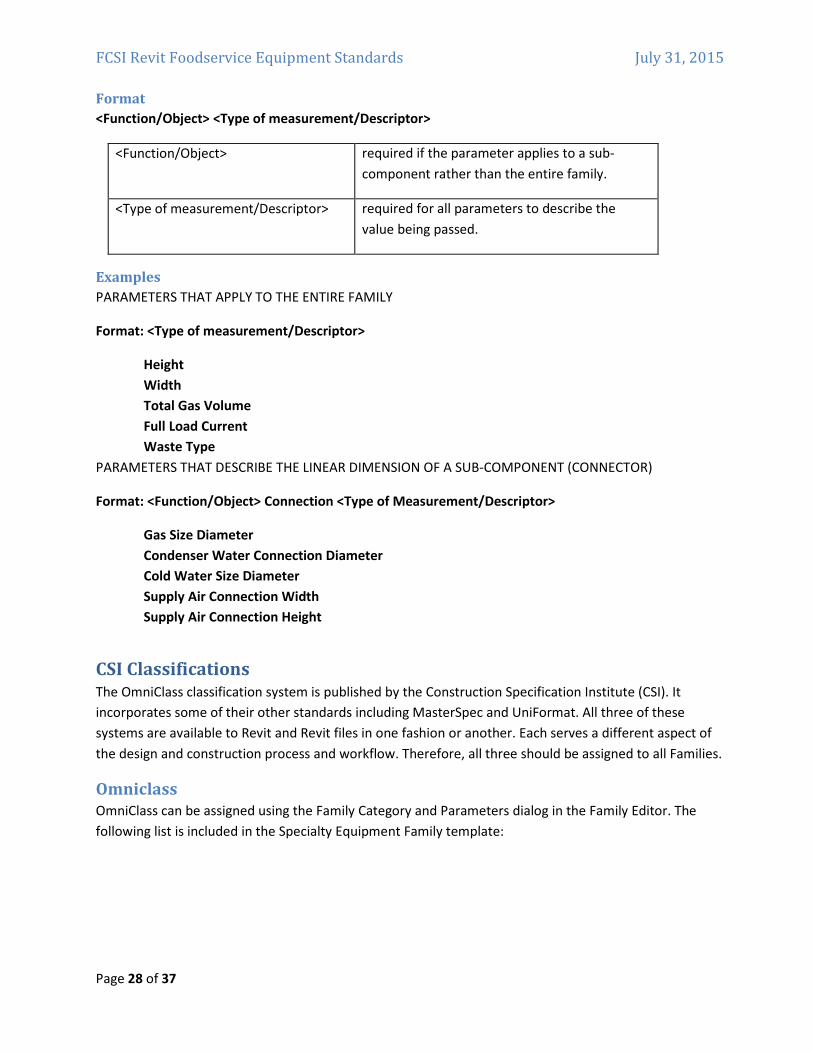
Format
<Function/Object> <Type of measurement/Descriptor>
<Function/Object> required if the parameter applies to a sub‐
component rather than the entire family.
<Type of measurement/Descriptor> required for all parameters to describe the
value being passed.
Examples
PARAMETERS THAT APPLY TO THE ENTIRE FAMILY
Format: <Type of measurement/Descriptor>
Height
Width
Total Gas Volume
Full Load Current
Waste Type
PARAMETERS THAT DESCRIBE THE LINEAR DIMENSION OF A SUB‐COMPONENT (CONNECTOR)
Format: <Function/Object> Connection <Type of Measurement/Descriptor>
Gas Size Diameter
Condenser Water Connection Diameter
Cold Water Size Diameter
Supply Air Connection Width
Supply Air Connection Height
CSI Classifications The OmniClass classification system is published by the Construction Specification Institute (CSI). It
incorporates some of their other standards including MasterSpec and UniFormat. All three of these
systems are available to Revit and Revit files in one fashion or another. Each serves a different aspect of
the design and construction process and workflow. Therefore, all three should be assigned to all Families.
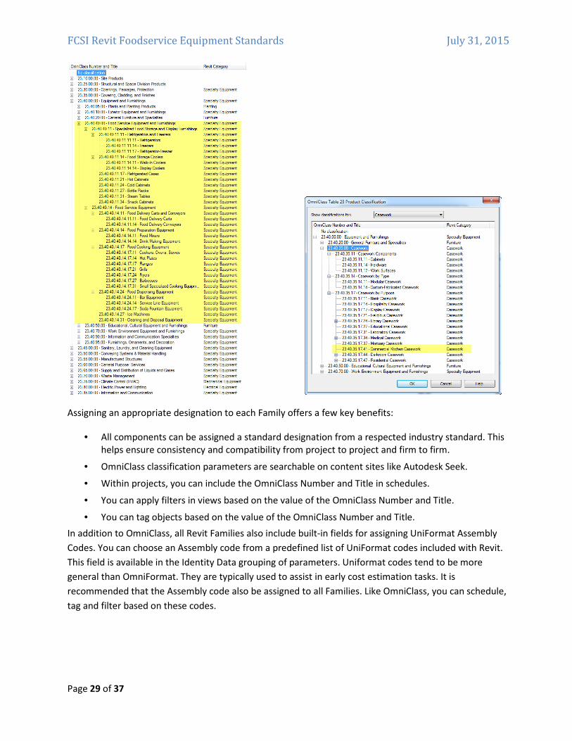
Omniclass
OmniClass can be assigned using the Family Category and Parameters dialog in the Family Editor. The
following list is included in the Specialty Equipment Family template:
FCSI Revit Foodservice Equipment Standards July 31, 2015
Page 29 of 37
Assigning an appropriate designation to each Family offers a few key benefits:
• All components can be assigned a standard designation from a respected industry standard. This
helps ensure consistency and compatibility from project to project and firm to firm.
• OmniClass classification parameters are searchable on content sites like Autodesk Seek.
• Within projects, you can include the OmniClass Number and Title in schedules.
• You can apply filters in views based on the value of the OmniClass Number and Title.
• You can tag objects based on the value of the OmniClass Number and Title.
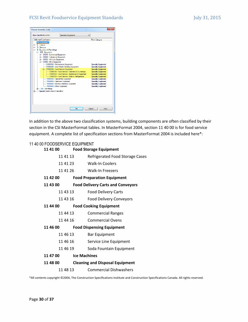
In addition to OmniClass, all Revit Families also include built‐in fields for assigning UniFormat Assembly
Codes. You can choose an Assembly code from a predefined list of UniFormat codes included with Revit.
This field is available in the Identity Data grouping of parameters. Uniformat codes tend to be more
general than OmniFormat. They are typically used to assist in early cost estimation tasks. It is
recommended that the Assembly code also be assigned to all Families. Like OmniClass, you can schedule,
tag and filter based on these codes.
FCSI Revit Foodservice Equipment Standards July 31, 2015
Page 30 of 37
In addition to the above two classification systems, building components are often classified by their
section in the CSI MasterFormat tables. In MasterFormat 2004, section 11 40 00 is for food service
equipment. A complete list of specification sections from MasterFormat 2004 is included here*:
11 40 00 FOODSERVICE EQUIPMENT
11 41 00 Food Storage Equipment
11 41 13 Refrigerated Food Storage Cases
11 41 23 Walk‐In Coolers
11 41 26 Walk‐In Freezers
11 42 00 Food Preparation Equipment
11 43 00 Food Delivery Carts and Conveyors
11 43 13 Food Delivery Carts
11 43 16 Food Delivery Conveyors
11 44 00 Food Cooking Equipment
11 44 13 Commercial Ranges
11 44 16 Commercial Ovens
11 46 00 Food Dispensing Equipment
11 46 13 Bar Equipment
11 46 16 Service Line Equipment
11 46 19 Soda Fountain Equipment
11 47 00 Ice Machines
11 48 00 Cleaning and Disposal Equipment
11 48 13 Commercial Dishwashers
*All contents copyright ©2004, The Construction Specifications Institute and Construction Specifications Canada. All rights reserved.
FCSI Revit Foodservice Equipment Standards July 31, 2015
Page 31 of 37
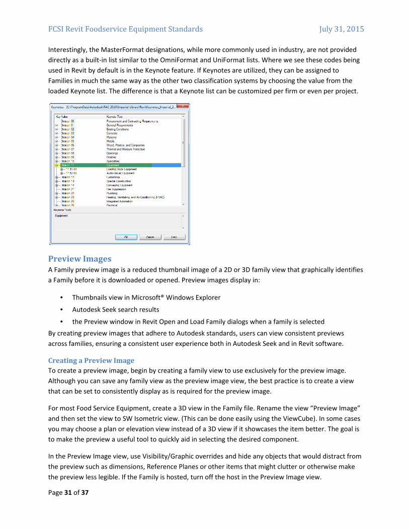
Interestingly, the MasterFormat designations, while more commonly used in industry, are not provided
directly as a built‐in list similar to the OmniFormat and UniFormat lists. Where we see these codes being
used in Revit by default is in the Keynote feature. If Keynotes are utilized, they can be assigned to
Families in much the same way as the other two classification systems by choosing the value from the
loaded Keynote list. The difference is that a Keynote list can be customized per firm or even per project.
Preview Images
A Family preview image is a reduced thumbnail image of a 2D or 3D family view that graphically identifies
a Family before it is downloaded or opened. Preview images display in:
• Thumbnails view in Microsoft® Windows Explorer
• Autodesk Seek search results
• the Preview window in Revit Open and Load Family dialogs when a family is selected
By creating preview images that adhere to Autodesk standards, users can view consistent previews
across families, ensuring a consistent user experience both in Autodesk Seek and in Revit software.
Creating a Preview Image
To create a preview image, begin by creating a family view to use exclusively for the preview image.
Although you can save any family view as the preview image view, the best practice is to create a view
that can be set to consistently display as is required for the preview image.
For most Food Service Equipment, create a 3D view in the Family file. Rename the view “Preview Image”
and then set the view to SW Isometric view. (This can be done easily using the ViewCube). In some cases
you may choose a plan or elevation view instead of a 3D view if it showcases the item better. The goal is
to make the preview a useful tool to quickly aid in selecting the desired component.
In the Preview Image view, use Visibility/Graphic overrides and hide any objects that would distract from
the preview such as dimensions, Reference Planes or other items that might clutter or otherwise make
the preview less legible. If the Family is hosted, turn off the host in the Preview Image view.
FCSI Revit Foodservice Equipment Standards July 31, 2015
Page 32 of 37
Choose Save As from the Application menu and click the Options button. In the Preview area, set the
Preview to use the Preview Image view that you set up.
Type Catalogs
A type catalog is a comma‐delimited TXT file that, when placed in the same directory as a Family, displays
a list of available Family Types onscreen when the Family is loaded into a project. You can select and load
just the Family Types that the current project requires, avoiding an unnecessary increase in project size
from unused Types and a long list of Types in the Type Selector. The Type Catalog also provides an
external means of editing the Family, as you can add and remove Types in the catalog (TXT) file.
Type Catalog Standards
The following standards are recommended by the RMCSG when creating type catalogs:
• Use any text editor to create Type Catalogs.
• Create Type Catalogs for Families that contain six or more Types.
• Name a Type Catalog file (TXT) with the same name as the Family file (RFA) that it supports and
place it in the same directory.
• Ensure that parameters in Type Catalogs are used within the Family file. It is not necessary to
have all of the Types in the Catalog in the Family file, but each parameter used in the file must be
resident in the Family and applied to geometry as appropriate.
To use feet and inches in the names of Family Types in the Type Catalog, you must format the names with
a quote mark after the foot or inch symbol as shown in the following table:
To display the type name… In the type catalog, enter…
48” x 60” 48”” x 60””
3’ – 6” 3’” –6””
For information on creating a type catalog, see “Creating Type Catalogs” in the Revit Help and Families
Guide.
Materials
If you will be assigning materials to your content and using them for photo‐realistic renderings, it is
recommended that you reserve highly detailed geometric representations for only the Fine level of detail.
Revit ships with an extensive library of materials. To ensure consistency in projects, all equipment
Families should use the FCSI Material Library. A material library is a collection of materials and related
assets. The FCSI Revit Standards Committee has prepared this library to share among content creators
and designers in an effort to obtain a uniform appearance in Revit families of foodservice equipment.
The library consists of commonly used materials in foodservice equipment manufacturing. Additional
materials may be added, but this is discouraged in an effort to keep the number of different materials to
a minimum. If materials must be added, the naming convention is QF_<material>-<Color>-<Finish
Modifier>. No commas shall be used. An underscore follows “QF” and the subsets are separated by
FCSI Revit Foodservice Equipment Standards July 31, 2015
Page 33 of 37
hyphens. The library may be downloaded from http://www.fcsi.org/?page=REVITStandards. The latest
version is FCSI 2014 Materials.adsklib.
To load a material library, you must be able to locate the FCSI 2014 Materials.adsklib file. Then in a Revit
project, click the Manage Tab > Settings Panel > Materials. In the Material Browser dialog, on the
browser toolbar, click the drop‐down menu > Open Existing Library. Browse to and select the
material library file and click open.
The material library will then display in the library list. Now you can copy materials from that library into
your projects. To share this library with others, merely provide them with a copy of the library.
Connectors
In Revit MEP, the connector connects the single family component with other components to create MEP
systems. Without a connector, an RME family would just be a static placeholder. In RAC, connectors can
be added to Families, but are not utilized in RAC projects. RAC does not have systems functionality, so
connectors are simply ignored by the software. However, if parameters are assigned to connectors, they
can be scheduled in RAC projects.
In Revit MEP, there are 5 kinds of connectors:
• Electrical Connector
• Duct Connector
• Pipe Connector
• Cable Tray Connector
• Conduit Connector
Connectors can be added to Specialty Equipment Families; however in RME they will not enjoy full
functionality. For example, piping connectors will fail to associate properly with the system designated in
the Family file. If connector functionality is critical to your Family’s functioning and behavior, consider
using an MEP category instead such as Plumbing Fixture or Mechanical Equipment. Such categories
should work well for hand sinks or exhaust hoods. However, they will be somewhat problematic for
equipment with multiple types of connections like refrigerators, ranges, ice makers, etc. These items are
really more appropriate in the Specialty Equipment category, so careful consideration must be given to
this issue and realistic expectations placed on the expected behavior of connectors in food service
equipment.
Before making the final decision however, a few additional related points are worthy of mention. First,
connectors do not work through linked files. This is true regardless of the category used for the Family. If
you wish to connect a Family’s connectors to a system and other equipment, all items must reside in the
same Revit file. This is unlikely given the current workflow employed by most design and engineering
firms today. The typical workflow employed is for each major discipline to perform their work in separate
files and then link to each other’s file in order to work with or print the entire project. Periodic updates of
any party’s file can be reloaded as needed via the Manage Links functionality. Since the food service
designer is often in a different firm than the consulting engineers, working in the same Revit file is
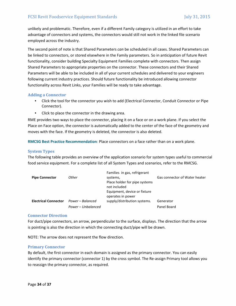
FCSI Revit Foodservice Equipment Standards July 31, 2015
Page 34 of 37
unlikely and problematic. Therefore, even if a different Family category is utilized in an effort to take
advantage of connectors and systems, the connectors would still not work in the linked file scenario
employed across the industry.
The second point of note is that Shared Parameters can be scheduled in all cases. Shared Parameters can
be linked to connectors, or stored elsewhere in the Family parameters. So in anticipation of future Revit
functionality, consider building Specialty Equipment Families complete with connectors. Then assign
Shared Parameters to appropriate properties on the connector. These connectors and their Shared
Parameters will be able to be included in all of your current schedules and delivered to your engineers
following current industry practices. Should future functionality be introduced allowing connector
functionality across Revit Links, your Families will be ready to take advantage.
Adding a Connector
• Click the tool for the connector you wish to add (Electrical Connector, Conduit Connector or Pipe
Connector).
• Click to place the connector in the drawing area.
RME provides two ways to place the connector, placing it on a face or on a work plane. If you select the
Place on Face option, the connector is automatically added to the center of the face of the geometry and
moves with the face. If the geometry is deleted, the connector is also deleted.
RMCSG Best Practice Recommendation: Place connectors on a face rather than on a work plane.
System Types
The following table provides an overview of the application scenario for system types useful to commercial
food service equipment. For a complete list of all System Types and scenarios, refer to the RMCSG.
Pipe Connector Other
Families in gas, refrigerant
systems, Gas connector of Water heater
Place holder for pipe systems
not included
Electrical Connector Power – Balanced
Equipment, device or fixture
operates in power
supply/distribution systems. Generator
Power – Unbalanced Panel Board
Connector Direction
For duct/pipe connectors, an arrow, perpendicular to the surface, displays. The direction that the arrow
is pointing is also the direction in which the connecting duct/pipe will be drawn.
NOTE: The arrow does not represent the flow direction.
Primary Connector
By default, the first connector in each domain is assigned as the primary connector. You can easily
identify the primary connector (connector 1) by the cross symbol. The Re‐assign Primary tool allows you
to reassign the primary connector, as required.
FCSI Revit Foodservice Equipment Standards July 31, 2015
Page 35 of 37
The primary connector of pipe and duct fittings should be located at coordinates (‐1, 0, 0). For other
Families, the location of the primary connector is not important.
Linking Connector
When there is more than one pipe connector, there is a choice for linking connectors.
• Linked connectors only have an effect when the system type is set to global for equipment or
fitting.
• Linking connectors on equipment makes it possible to propagate engineering data, allowing you
to use equipment as an inline component in a system.
• Linking connectors on fittings should include the primary connector.
Connector Mapping
Edit Element Properties for the connector to define parameters for the connector. Click the browse
button in the far right column to display a dialog where you can map connector parameters to family
parameters (or shared parameters) with the same units. Connector mapping makes the connector
parametric with the family.
Connector Descriptions
In equipment with multiple connectors, it can be difficult to determine the function of each connector.
To make it easier to identify the function of connectors in the family, add connector descriptions. These
descriptions display in the Select Connector dialog.
FCSI Revit Foodservice Equipment Standards July 31, 2015
Page 36 of 37
SECTION 3: TESTING GUIDELINES To ensure the quality of Revit Family content, thoroughly test Families before using them in production
or sharing them with others. Perform general testing on a Family when it is:
• open in the Family Editor
• loaded into a project
Use the criteria in the checklists below to test Families in each of the above environments. When testing
Families in projects, test them both in a generic sandbox project created from a simple template and a
project typical of the kind of project where it is likely to be used most frequently.
TIP: For large content creation projects, it is recommended that “spot checking” or random testing of
10% of the content be performed by a tester who is not the content creator.
Family Editor Testing Criteria
� Test all Family parameters to ensure that the geometry flexes/adjusts correctly when the Family
parameters are modified.
� Test all Family Types – change the Type, apply it, and inspect the geometry to verify that the
dimensions and relationships are maintained.
� If a Type Catalog is being used for the Family, save such Type testing until you load it into a
project environment.
� In a host‐based Family, verify that the host flexes as expected. Change the host thickness and
ensure that the family geometry adjusts appropriately.
� Verify that the Family preview image is using the designated Preview view.
� Check all views to ensure that the Family displays appropriately in different detail levels and
when different Model Graphics styles are applied.
� Test constraints:
o Test the handles on the edge of the geometry and make sure that all geometry is
constrained to either a reference plane or a reference line.
o Test the dimension parameter to make sure that the reference plane or line is being
adjusted by the parameter and not the actual geometry.
Project Testing Criteria For Revit
� Using a test project, load the Family in a project environment, and check all views for anomalies.
If the Family includes a Type Catalog, use it to load the Family and several of its Types.
� Inspect the Family appearance in all views (plan, reflected ceiling plan, elevation, Section, 3D) at
all detail levels (Coarse, Medium, Fine).
� Inspect the Family appearance in different Model Graphics Styles: Wireframe, Hidden Line,
Shading, and Shading with Edges.
� Test all Family Types – change the Type, apply it, and inspect the geometry to verify that the
dimensions and relationships are maintained.
� Create new Types and modify all parameters, checking all views for anomalies.
� For hosted Families:
o Place hosted Families into the provided host thicknesses and confirm Families work in all
FCSI Revit Foodservice Equipment Standards July 31, 2015
Page 37 of 37
hosts appropriate to the Families use, including in‐place walls and mass elements.
o Modify the host thickness by 25% ‐ 400%, and check for unconnected geometry and/or
plan representations that may be disconnected from the geometry.
o Re‐inspect the Family appearance in all views to ensure that the geometry displays as
expected.
� Dimension to all references and snap all references to walls.
� Test the following commands on geometry created in the Family:
o Copy/Paste
o Rotate
o Mirror
� Test the Family in an actual project, verify its performance, and ensure that the project matches
the design intent of the Family.
Additional Files Several documents have been researched to produce this document and are included herein by
reference.
The following resources are available from Autodesk for working with both Revit model content and
Autodesk Seek.
AUTODESK REVIT MODEL CONTENT STYLE GUIDE: The purpose of this guide is to define Autodesk
guidelines and standards for model content creation in Revit® Architecture, Revit® MEP, and Revit®
Structure. Model content refers to the two‐dimensional and three‐dimensional standard component
families that are used to create elements that represent manufactured content (for example, windows,
furnaces, heat pumps, and structural steel members).
AUTODESK METADATA STYLE GUIDE AND PRODUCT WORKBOOK: The Autodesk Metadata Style Guide
defines styles and formatting rules that manufacturers, content service organizations, and content
specialists must abide by so that the content that they produce can be loaded into the Autodesk Seek
staging environment.
Download at: http://seek.autodesk.com/revit.htm
Revision Date: 31July2015
i Visit the Building Coder blog at: http://thebuildingcoder.typepad.com