Revisiting Water Injection for Commercial Aircraft - NASA · PDF fileAnother study2 evaluated...
8
World Aviation Congress ® & Exposition, November 2004, Reno, NV, USA, Session: Turbine Engine Technologies Paper Number 2004-01-3108 Revisiting Water Injection for Commercial Aircraft David L. Daggett, Silvio Ortanderl The Boeing Commercial Airplane Group David Eames Rolls-Royce Corporation Jeffrey J. Berton, Christopher A. Snyder NASA Glenn Research Center Copyright © 2004 SAE International ABSTRACT Water injection is an old aviation technology that was previously used to enable an increase in engine power during takeoff. If water injection is used without increasing thrust, the cooling effects of water injection could enable longer engine component life and also result in large reduction in NOx emissions. The two preferred methods of aircraft engine water injection are: direct injection into the combustor, and misting of the conditioned water before the engine’s compressor. Combustor injection could achieve up to 90% NOx reduction and offer few implementation challenges as it has been used in the industrial turbine engine sector for over 30 years. For low pressure compressor water misting, the rate of water flow is limited, and so could only achieve a 50% NOx reduction level but would offer larger reductions in turbine inlet temperature. This injection method would offer larger operator savings, due to improved engine hot section life, but more risk. Newer high bypass ratio engines experience higher thrust lapse rates with altitude, which results in higher core temperatures. In order to reduce these temperatures, both water injection systems are evaluated for use all the way to top of climb. Due to the cooling action of water evaporation, when keeping engine thrust constant, a large reduction in turbine inlet temperature would be experienced which could result in increased engine hot section life and reduced operator costs. This would reduce the peak temperatures of the hot section during takeoff, where about a third of the turbine blade’s life is consumed. INTRODUCTION As air traffic continues to grow, airports will face increased environmental pressure. As such, airports are implementing strategies, such as emissions-based landing fees, to encourage the development and operation of low emissions aircraft. These market forces, together with the public’s increasing earth consciousness, and related regulatory pressures are driving airlines to not only demand more fuel efficient aircraft, but now ones that also have lower NOx emissions. However, airlines cannot afford environmental technology in any sense that transcends their own preservation. Therefore, technology must be developed that will satisfy both global environmental needs as well as those of airlines operating in a fiercely competitive market. Water injection was first used over 45 years ago on commercial transport aircraft to increase thrust. Boeing 707-120 aircraft with Pratt & Whitney JT3C-6 engines and later, the Boeing 747-100 & 200 aircraft with Pratt & Whitney JT9D-3AW and -7AW engines, all used water injection for thrust augmentation. With this extensive heritage, water injection on aircraft should be well- understood. In the industrial gas turbine sector, water injection has continued to be used, but for NOx emissions reduction. This reduction level can approach 90% reduction and can also be used to boost engine power. With the advent of more powerful engines, water injection has been abandoned in the aviation sector, but aero-derivative industrial engines have continued to use the technology and have improved upon it during this time. The objective of a recent study 1 was to evaluate the feasibility of using water injection once again on commercial aircraft, but this time for emissions reduction.
Transcript of Revisiting Water Injection for Commercial Aircraft - NASA · PDF fileAnother study2 evaluated...

World Aviation Congress ® & Exposition, November 2004, Reno, NV, USA, Session: Turbine Engine Technologies
Paper Number 2004-01-3108
Revisiting Water Injection for Commercial Aircraft
David L. Daggett, Silvio Ortanderl The Boeing Commercial Airplane Group
David Eames Rolls-Royce Corporation
Jeffrey J. Berton, Christopher A. Snyder NASA Glenn Research Center
Copyright © 2004 SAE International
ABSTRACT
Water injection is an old aviation technology that was previously used to enable an increase in engine power during takeoff. If water injection is used without increasing thrust, the cooling effects of water injection could enable longer engine component life and also result in large reduction in NOx emissions.
The two preferred methods of aircraft engine water injection are: direct injection into the combustor, and misting of the conditioned water before the engine’s compressor. Combustor injection could achieve up to 90% NOx reduction and offer few implementation challenges as it has been used in the industrial turbine engine sector for over 30 years. For low pressure compressor water misting, the rate of water flow is limited, and so could only achieve a 50% NOx reduction level but would offer larger reductions in turbine inlet temperature. This injection method would offer larger operator savings, due to improved engine hot section life, but more risk.
Newer high bypass ratio engines experience higher thrust lapse rates with altitude, which results in higher core temperatures. In order to reduce these temperatures, both water injection systems are evaluated for use all the way to top of climb.
Due to the cooling action of water evaporation, when keeping engine thrust constant, a large reduction in turbine inlet temperature would be experienced which could result in increased engine hot section life and reduced operator costs. This would reduce the peak temperatures of the hot section during takeoff, where about a third of the turbine blade’s life is consumed.
INTRODUCTION
As air traffic continues to grow, airports will face increased environmental pressure. As such, airports are implementing strategies, such as emissions-based landing fees, to encourage the development and operation of low emissions aircraft. These market forces, together with the public’s increasing earth consciousness, and related regulatory pressures are driving airlines to not only demand more fuel efficient aircraft, but now ones that also have lower NOx emissions. However, airlines cannot afford environmental technology in any sense that transcends their own preservation. Therefore, technology must be developed that will satisfy both global environmental needs as well as those of airlines operating in a fiercely competitive market.
Water injection was first used over 45 years ago on commercial transport aircraft to increase thrust. Boeing 707-120 aircraft with Pratt & Whitney JT3C-6 engines and later, the Boeing 747-100 & 200 aircraft with Pratt & Whitney JT9D-3AW and -7AW engines, all used water injection for thrust augmentation. With this extensive heritage, water injection on aircraft should be well-understood.
In the industrial gas turbine sector, water injection has continued to be used, but for NOx emissions reduction. This reduction level can approach 90% reduction and can also be used to boost engine power. With the advent of more powerful engines, water injection has been abandoned in the aviation sector, but aero-derivative industrial engines have continued to use the technology and have improved upon it during this time.
The objective of a recent study1 was to evaluate the feasibility of using water injection once again on commercial aircraft, but this time for emissions reduction.
Another study2 evaluated using water injection for emergency thrust augmentation. This data validated the earlier study results and also addressed some of the cost benefits if an engine were to be specifically designed to take advantage of the thrust benefits.
DISUSSION
STUDY METHOD - The following discusses two engine and airframe water injection systems for a medium to large sized commercial aircraft. The feasibility of using water injection during takeoff and all the way to top of climb as well as potential engine turbine life benefits are analyzed.
The first engine water injection scheme considered is a traditional combustor water injection system where water is introduced directly into the combustor. The second system is a water misting system where water is finely atomized and injected before the Low Pressure Compressor (LPC) and/or the High Pressure Compressor (HPC.) Each type of water injection system will require a different airframe support system due to different NOx reduction efficiencies … the combustor injection system being most efficient at reducing NOx.
COMPRESSOR MISTING SYSTEM- …When water is finely atomized and sprayed into the compressor inlet, the evaporation of the water droplets lowers the temperature of the air and consequently, air density, compressor delivery and thrust are all increased3. The combustor inlet air temperature thereby drops, reducing NOx formation. In addition, as thrust has now been increased by boosting the mass flow through the engine, the throttles can be retarded slightly to keep the same level of thrust as before water misting. This further lowers NOx formation. For all water injection systems, adding water to the engine does reduce the combustor flame temperature which would normally result in a fuel efficiency loss. However, these thermal losses are overcome on the compressor water misting systems by engine efficiency improvements.
Figure 1 shows a conceptual aircraft engine water misting system, which is very similar to the JT3C-6 engine system used on early Boeing 707 aircraft. This concept injects water into the LPC through 24 HPC air-assisted atomization nozzles. Water can also be delivered before the HPC during cold atmospheric conditions.
WaterMisted water injection points
WaterWaterWaterMisted water injection points
Figure 1. Water misting intercooler concept sprays water into
LP and/or HP compressor with HPC air to assist in water atomization
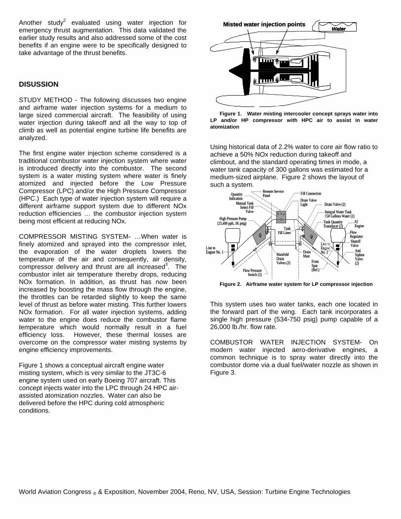
Using historical data of 2.2% water to core air flow ratio to achieve a 50% NOx reduction during takeoff and climbout, and the standard operating times in mode, a water tank capacity of 300 gallons was estimated for a medium-sized airplane. Figure 2 shows the layout of such a system.
QuantityIndication
Remote ServicePanel Fill Connection
Drain ValveLight
TankFill Lines
Drain Valve (2)
Integral Water Tank150 Gallons Water (2)
Tank QuantityTransducer (2)
#2Engine
Flow RegulatorShutoffValve
AntiSiphonValve(2)Front
Spar(Ref.)
Drain Mast
Flow PressureSwitch (2)
ManifoldDrainValves (2)
Manual TankSelect Fill
Valve
Line toEngine No. 1
vp
Line toEngineNo. 2
vp tt
High Pressure Pump (25,400 pph, 1K psig)
QuantityIndication
Remote ServicePanel Fill Connection
Drain ValveLight
TankFill Lines
Drain Valve (2)
Integral Water Tank150 Gallons Water (2)
Tank QuantityTransducer (2)
#2Engine
Flow RegulatorShutoffValve
AntiSiphonValve(2)Front
Spar(Ref.)
Drain Mast
Flow PressureSwitch (2)
ManifoldDrainValves (2)
Manual TankSelect Fill
Valve
Line toEngine No. 1
vp
Line toEngineNo. 2
vp tttt
High Pressure Pump (25,400 pph, 1K psig)
Figure 2. Airframe water system for LP compressor injection
This system uses two water tanks, each one located in the forward part of the wing. Each tank incorporates a single high pressure (534-750 psig) pump capable of a 26,000 lb./hr. flow rate.
COMBUSTOR WATER INJECTION SYSTEM- On modern water injected aero-derivative engines, a common technique is to spray water directly into the combustor dome via a dual fuel/water nozzle as shown in Figure 3.
World Aviation Congress ® & Exposition, November 2004, Reno, NV, USA, Session: Turbine Engine Technologies

World Aviation Congress ® & Exposition, November 2004, Reno, NV, USA, Session: Turbine Engine Technologies
Figure 3. Conceptual water injection system directly feeding
water into the combustor
By atomizing the fuel and water together inside the combustor, a better distribution of water could be maintained. It also reduces the amount of water required over compressor misting because it is directed only to where the water is needed … inside the combustor. This is a well-proven design with few, if any, unknowns for use in aircraft. For a water to fuel ratio of 0.5:1, to achieve roughly a 50% NOx reduction, using standard times in mode for takeoff/climbout and fuel consumption rates for a large engine, the calculated water consumption rate suggests a water tank capacity of 135 gallons. Figure 4 shows the airframe layout.
QuantityIndication
Remote ServicePanel
Fill ConnectionDrain Valve& Light
TankFill Line
Drain Valve
Water Tank(135 Gallons Water)
Tank QuantityTransducer
#2Engine
Flow Regulator
ShutoffValve
AntiSiphonValve
Drain Mast
Flow PressureSwitch (2)
ManifoldDrainValve
Manual TankSelect Fill Valve
High PressurePump (22,700 pph, 1K psig)
Line toEngine No. 1
p
Line toEngineNo. 2
t
v
QuantityIndication
Remote ServicePanel
Fill ConnectionDrain Valve& Light
TankFill Line
Drain Valve
Water Tank(135 Gallons Water)
Tank QuantityTransducer
#2Engine
Flow Regulator
ShutoffValve
AntiSiphonValve
Drain Mast
Flow PressureSwitch (2)
ManifoldDrainValve
Manual TankSelect Fill Valve
High PressurePump (22,700 pph, 1K psig)
Line toEngine No. 1
p
Line toEngineNo. 2
tt
vv
Figure 4. Airframe water system for direct combustion
injection system.
SYSTEM PERFORMANCE COMPARISONS- Figure 5 compares both systems at about a 50% NOx reduction level. The water misting system (water is injected into the Low Pressure Compressor) exhibited better Specific Fuel Consumption (SFC) and Turbine Inlet Temperature (T4) reductions than the combustor injected system. This is due to compressor performance improvements as well as more water being introduced into the engine core
which further reduced T4 over the combustor injection system.
Figure 5. LPC misting system achieved greater SFC and T4 improvements.
A small system weight penalty of less than 360 lbs. for either system is anticipated which would have an inconsequential impact on airplane fuel efficiency performance. Although a 1/3 of the water in the storage tanks will be used during the takeoff roll, some fuel would have to be left off the airplane when it is loaded to 100% payload capability so that the aircraft’s Maximum Takeoff Gross Weight limit is not exceeded. During these infrequent instances, water injection might not be used so that no passengers are left behind.
Noise is anticipated to decrease by 0.61 dba for the LPC water misting system due to increased core mass flow from the water and the resulting decrease in jet velocity needed to maintain the same thrust level.
When introducing water into the compressor, surge issues may become more prevalent than with combustor injection systems. This needs to be further addressed.
WATER INJECTION TO Top Of Climb (TOC) - The airplane and engine performance impacts of two systems were studied (i.e. combustor injection and LPC misting.) For each configuration, the water flow rate was adjusted to achieve 50-65% NOx reduction during takeoff up to 3,000 ft. The water flow rate was then reduced to achieve either 20R or 50R reduction in T4 to top of climb for engine life improvement.
The top line in Figure 6 shows a modern 1990s baseline 85,000 lb. thrust class engine’s T4 profile while the airplane climbs to 5,000 ft altitude (13.7 nmi from the takeoff point.) The dotted line below shows the T4 profile of an engine with water injected into the combustor to achieve a 65% NOx reduction during takeoff to 3,000 ft altitude. At that point, the water injection rate is decreased to achieve either a 20R or 50R constant

decrease in T4. The bottom dashed line shows the T4 profile of an engine with LPC water misting to achieve a constant 50% NOx reduction during takeoff. In this instance, the LPC water misted engine achieved a lower T4 because the water misting rate was some 60% higher (26,365 to 31,340 lb/hr/engine) than for the combustor water injected engine (14,750 to 19,830 lb/hr/engine.)
World Aviation Congress ® & Exposition, November 2004, Reno, NV, USA, Session: Turbine Engine Technologies
Figure 6. Water misting achieved a lower T4 to 3,000 ft and then water flow was varied to achieve either 20R or 50R reduction in T4 to top of climb.
Table 1 shows the amount of water used for each case. Due to the flame temperature reduction efficiency of water injection, this system only required 1,480 lb of water (920 lb. less) to 3,000 feet to achieve a 65% NOx reduction rate as compared to LPC water misting that achieved a 50% NOx reduction rate. However, this temperature quenching efficiency also resulted in a 59 lb. increase in fuel use due to thermal efficiency losses. When using LPC water misting, the compressor efficiency improvement offset any thermal losses suffered and resulted in a 71 lb. fuel savings instead of a 59 lb. penalty during takeoff. Table 1 . Combustor water injection uses least amount of water for largest takeoff NOx reduction. Large amounts of water are required for its use to Top Of Climb (TOC.)
Water (lb.) Delta Fuel (lb.)Takeoff NOx reduction
65% reduction (Combustor)
1,480 +59
50% reduction (Compressor)
2,400 -71
20F T4 reduction Takeoff + TOC (combustor)
4,470 +175
Takeoff + TOC (compressor)
3,560 -86
50F T4 reduction Takeoff + TOC (combustor)
8,970 +350
Takeoff + TOC (compressor)
5,300 -109
When continuing to use water all the way to the top of climb, the same fuel efficiency effects carried over as well, with the combustor injection system resulting in more fuel use than the LPC water misting system.
When using water to reduce T4 during climb to cruise, the water misting system needs less water than combustor injection to achieve the same amount of turbine inlet temperature reduction. This is again due to the improvement in compressor efficiency achieved when using water misting.
While the weight penalty for carrying water for the takeoff phase may be acceptable, the much higher weights required to use it all the way to top if climb would impose prohibitive payload penalties on the aircraft.
HOT SECTION IMPACT - … The hot section part of an engine consists of the combustor and high pressure turbine assembly. Due to the high temperatures, pressures and rotational speeds of the components in these areas, the hot section is exposed to a harsher environment than the rest of the engine. This results in thermo-mechanical fatigue and therefore limits service life. These components can have a significantly lower service life than the rest of the engine4 as illustrated in Figure 7
Figure 7. The hot section of an engine can have a shorter life
than the rest of the engine due to the high operating temperature.
It is difficult determine a fatigue limit or a stress at high temperatures below which no failures will occur5. Yet, Table 2 illustrates the design practices, and service life experience, of a modern (i.e. 1980’s vintage GE CF6) turbine engine that is still in use today6. For standard day conditions, the highest T4 value occurs during takeoff, which consumes about 36% of the turbine blade’s life

during 300 hrs (3%) of its 18,000 hour design life. During hot day takeoff conditions, the entire blade’s life would be consumed in only 250 hours of continuous operation.
World Aviation Congress ® & Exposition, November 2004, Reno, NV, USA, Session: Turbine Engine Technologies
Table 2. 36% of a HP turbine life is consumed during the short takeoff period
Condition % Life Used
Time [hrs]
Takeoff Max. Climb Max. Cruise
Balance Total
36 49 15
< 0.1 100
300 3,300 7,200 7,200 18,000
By reducing T4 temperatures, turbine life will increase. Figure 6 showed that using water injection during takeoff would reduce the peak turbine inlet temperatures some 436° for the water misting case and 115° for the combustor injection case.
Figure 8 illustrates that there is a logarithmic relationship between T4 and turbine life. Namely, for a small decrease in T4, a large increase in turbine life will occur.
Figure 8. Small decreases in T4 result in large increases in turbine life.
Depending on the amount of water injected, and the susceptibility of the turbine blade metal to temperature, the most severe life-limiting part of the blade’s life (takeoff) can almost be eliminated. Thus, for the conditions shown in Table 2, the turbine blade life could conceivably be significantly extended when takeoff conditions are leveled to the same as those during climb conditions. Further improvements can be achieve when reducing climb T4 temperatures as well. Six water injection cases are presented in order to evaluate the tradeoffs between quantity of water required and the potential for turbine life improvement. Table 3 shows both combustor water injection and compressor water misting systems were compared to a baseline engine. Water was used for takeoff only in cases 2 and 3. Cases 4 through 6 used water for takeoff and climb.
Table 3. Water injection scenarios studied
Case#
Scenario
1 Base Engine 2 Takeoff combustor water injection for 65% NOx
reduction 3 Takeoff LPC water misting for 50% NOx
reduction 4 Case #3 plus HPC water misting for 20R
reduction in T4 to top of climb 5 Case #3 plus HPC water misting for 50R
reduction in T4 to top of climb 6 Case #2 plus water injection to top of climb with
50R reduction Figure 9 shows that for takeoff, the water misting system (case #3) is estimated to provide a slightly greater turbine life improvement over combustor injection (case #2) because it used more water to achieve a larger T4 reduction. Further studies need to be completed to decide if the additional water weight, system complexity and operating uncertainties of water misting is worthwhile over the proven combustor injection system. When also using water during climb to altitude, turbine life may be further improved. Case #4 shows that a 20R reduction in T4 would slightly lengthen turbine life and a 50R reduction (Case #5) might extend the designed turbine blade life beyond that of the rest of the engine. Thus, somewhere between a 20R and 50R reduction in T4 during climb when using HPC misting would be optimal. However, the severe weight penalties of carrying this much water will probably be prohibitive to airline operators as it would displace revenue passengers. Case 6 shows an even more prohibitive water weight penalty of using water injection during takeoff and climb to altitude. The takeoff combustor water injection scenario (case #2) predicts the greatest turbine life improvement for the least amount of water used.
Figure 9. Increasing water injection rate reduces T4 temperature which will increases turbine life.

The number of takeoff and landing cycles that a turbine blade is exposed to also determines the blade’s life. This is termed “Life Cycle Fatigue.” In this instance, the LCF limit of the blade is sufficiently high that it is not a limiting factor in the blade’s ultimate life. Combustor wall radiative heat loading may also be reduced which will reduce wall temperatures and could therefore also increase combustor life.
MAINTENANCE BENEFITS - … The possible engine maintenance cost benefits of water injection are difficult to estimate. These costs are also considered competitive information, making data gathering even more difficult.
In order to assess the value of water injection to an airplane operator, the Cash Airplane Related Operating Cost (CAROC) is used to estimate the engine maintenance costs savings of this system. Figure 10 illustrates the CAROC breakdown for a medium-sized airplane on a 3,000 nmi mission and highlights the engine maintenance portion. As this makes up a sizable portion of the CAROC, reducing engine maintenance could have a significant impact on airplane operating cost.
World Aviation Congress ® & Exposition, November 2004, Reno, NV, USA, Session: Turbine Engine Technologies
Figure 10. Airplane operating costs could be reduced if engine maintenance were reduced.
Each engine make and model typically has a different reliability record; some engines experiencing more required maintenance in specific components than others. However, the hot section of an engine does tend to require a significant share of maintenance when compared to other components. Figure 11 illustrates the engine removal rates, over a year, for two different engine manufacturers. It shows that turbine components account for between 25% and 40% of the reason engines are removed from service. Combustors appear to make up a very small part of the engine removal pie.
For engines that experience higher removal rates due to turbine blade temperature distress, water injection would no doubt be of more value.
Figure 11. Engine removal due to hot section maintenance varies by engine type.
For whatever reason an engine is removed from service, the turbine often then also receives attention which contributes a significant portion to the overhaul cost.
ECONOMIC ANALYSIS - … Preliminary system costs were calculated. These included: (1) the capital costs of purchasing the water injection system, (2) the cost of the conditioned water (which is substantially less expensive now due to new reverse osmosis systems), (3) the water servicing cost at the airport, (4) airframe maintenance costs. (5) the cruise fuel impact from having to carry 360 lb. of system weight. The estimated engine maintenance cost savings, based on turbine life extension predictions were included.
Figure 12 shows a breakdown of the water injection costs and also an estimated average engine maintenance savings an airline operator might experience. As shown, the cost savings from the reduced engine maintenance could well offset the added costs of water injection.
Figure 12. Maintenance savings offset water injection costs
EMISSIONS BENEFIT – NOx generation is primarily a function of temperature; higher combustor flame temperatures lead to higher NOx emissions7. Many years ago, water injection was shown to be highly effective in reducing smoke as well as NOx emissions8. It has since been used in many industrial aero-derivative gas turbine engines to reduce NOx emissions. In these

engines, water injection’s impact on engine emissions, maintenance and costs are well documented9.
Using a NASA Glenn numeric engine modeling performance program and Boeing airplane performance/emissions decks for validation, Figure 13 shows the present airplane NOx emissions profile and the LPC water misted NOx profile for a 777-200 aircraft. At 3,560 feet (11 mi), the 300 gallons of water are exhausted. At this point, the amount of NOx saved will have been 49.2 lb., achieving a 47% reduction in takeoff and climbout NOx. This includes the NOx reduction due to the overall fuel savings of using LPC water misting.
World Aviation Congress ® & Exposition, November 2004, Reno, NV, USA, Session: Turbine Engine Technologies
Figure 13. Water misting during takeoff and climbout reduces NOx by 49 lbs. on a 777 aircraft
Even though water injection is quite successful in reducing NOx emissions during takeoff, low emissions combustors are still needed. Figure 14 shows the amount of NOx emissions generated over a 3,000 nmi mission for a Boeing 777-200ER aircraft. Although the NOx emissions rate is high during takeoff and initial climbout, most NOx is generated during the long cruise and climb period where water injection is impractical to use due to the large quantity of water that would be required.
Figure 14. Low NOx combustors are still needed to reduce emissions during climb and cruise.
One of the possible negative aspects of water injection is its tendency to generate more HC and CO emissions. However, for high OPR engines, HC and CO emissions have been shown to remain relatively unaffected for the water injection rates being considered in this study. At higher rates (e.g. 1:1 water to fuel ratio), both HC and CO can climb precipitously10.
Previous data has shown that water injection rates of up to 1:1 water to fuel ratios may be beneficial in reducing smoke emissions. Figure 15 shows an example of the relationship of water injection to smoke emissions reduction11. It is unknown if this relationship will apply to current technology engines and how water injection will affect PM2.5 particulate emissions characteristics, but work is under way to quantify this relationship.12
Figure 15. Past tests have shown smoke reduction when using water injection .
OPERABILITY AND OTHER ISSUES- There could be other unforeseen impacts to the engine, such as turbine blade coating impacts, compressor blade erosion from unvaporized water droplets and compressor surge margin deterioration, which would need to be resolved by performing engine endurance tests. CONCLUSION
This optional aircraft emissions reduction technology could reduce takeoff NOx emissions more than 50% and has the possibility to reduce the operating cost of the aircraft. The minimal aircraft system weight and performance penalties should be more than offset by improved engine hot section life benefits. Water injection would best be used only during takeoff and a portion of climbout. This would be a worthwhile procedure for aircraft operating at less than maximum takeoff gross weight (i.e. less than 100% passenger load factor.)
When using water injection throughout climb, turbine life would further improve but the water weight penalties

World Aviation Congress ® & Exposition, November 2004, Reno, NV, USA, Session: Turbine Engine Technologies
would present unacceptable payload and airplane performance penalties.
Although the compressor water misting system offers better engine performance, the low-risk combustor injection system may be preferable. This is because of the many years it has been operating in the industrial power generating sector and the lower amount of water required for airplane applications.
Although the technology needs to be further developed for aircraft, it appears to be feasible13. The apparent economic and environmental benefits of water injection may well serve both airline survival and earth justice needs.
ACKNOWLEDGMENTS
The authors would like to thank R. Plencner , M. Goldstein and T. Strazisar of NASA Glenn Research Center as well as B. Glover of Boeing Commercial Airplanes for supporting this research. REFERENCES
1 Daggett, D. L., “Water Misting & Injection of Commercial Aircraft Engines to Reduce Airport NOx”, NASA Contractor Report, CR 2004-212957, 3/2004.
2 Eames, D.J.H., “Short Haul Civil Tiltrotor Contingency Power System Preliminary Design”, NASA contractor report, NAS3-97029, 12/1998
3 Hines, W.R., “Gas Turbine Engine with Water Injection”, U.S. Patent 6,012,279, 1/11/2000
4 Davis, D.Y., Sterns, E. M., ”Energy Efficient Engine Flight Propulsion System Final Design and Analysis”, NASA CR-168219, 1985
5 Zaretsky, E. V., ”Weibull-Based Design Methodology for Rotating Aircraft Engine Structures“, NASA/TM-2002-211348, June 2002
6 Malila, E. E., Lenahan, D.T., Thomas, T.T., “High Pressure Turbine Test Hardware Detailed Design Report” , NASA CR-167955, June 1982
7 Lefebvre, Arthur, Gas Turbine Combustion, Taylor & Francis, 1983.
8 Lefebvre, A.H. and Durrent. T., “Design Characteristics Affecting Gas Turbine Combustion Performance”, SAE Preprint 240C, also Esso Air World, vol 13, no. 3, pp 64-69, 1960.
9 Castaldini, C., “Evaluation of Water Injection Impacts for Gas Turbine NOx Control at Compressor Station”, GRI-90/0124, Gas Research Institute, June 1990
10 Bahr, D.W., “Technology for the Reduction of Aircraft Turbine engine Exhaust Emissios”, Paper 29, Atmospheric Pollution by Aircraft Engines, AGARD CP-125, Advisory Group for Aerospace Research & Development, 1973
11 Marchionna, N. R., et. al., “The effect of water injection on nitric oxide emissions of a gas turbine combustor burning ASTM Jet-A fuel”, NASA Technical Memorandum, TM X-2958, Dec. 1973
12 Personal conversation with Dale Shouse, Air Force Aero Propulsion Laboratory, Wright-Patterson Air Force Base, Ohio, 2004 13 Daggett, D.L, et. al., “Water injection on commercial aircraft to reduce airport NOx”, AIAA-2004-4198, July 2004.