REVISITING ALGORITHMS IN ARCHITECTURAL DESIGN · PDF fileAin Shams University Faculty of...
261
Ain Shams University Faculty of Engineering Departement of Architecture REVISITING ALGORITHMS IN ARCHITECTURAL DESIGN “TOWARDS NEW COMPUTATIONAL METHODS” By Hazem Mohamed Talaat El Daly B.Sc. Architecture. Ain Shams University A Thesis Submitted in Partial Fulfillment Of the Requirements of Phd Degree in Architecture Supervised by Prof. Dr. Yasser Mansour Head of Departement of Architecture Ain Shams University Faculty of Engineering Prof. Dr. Medhat Dorra Head of Departement of Architecture Cairo University Faculty of Engineering Prof. Dr. Khaled Dewidar Professor of Architecture Departement of Architecture Ain Shams University Faculty of Engineering Dr. Mohamed Sobh Lecturer of computer Ain Shams University Faculty of Engineering
Transcript of REVISITING ALGORITHMS IN ARCHITECTURAL DESIGN · PDF fileAin Shams University Faculty of...

Ain Shams University Faculty of Engineering Departement of Architecture
REVISITING ALGORITHMS IN ARCHITECTURAL DESIGN
“TOWARDS NEW COMPUTATIONAL METHODS”
By
Hazem Mohamed Talaat El Daly B.Sc. Architecture. Ain Shams University
A Thesis Submitted in Partial Fulfillment Of the Requirements of
Phd Degree in Architecture
Supervised by
Prof. Dr. Yasser Mansour Head of Departement of Architecture
Ain Shams University Faculty of Engineering
Prof. Dr. Medhat Dorra Head of Departement of Architecture
Cairo University Faculty of Engineering
Prof. Dr. Khaled Dewidar Professor of Architecture
Departement of Architecture Ain Shams University Faculty of Engineering
Dr. Mohamed Sobh Lecturer of computer Ain Shams University Faculty of Engineering

i
ABSTRACT
During the last two decades new forms are added to architecture,
which differ radically from the previous forms. The increasing
sophistication of software, has led to an already recognizable
computer style characterized by smooth, digitally rendered
surfaces, complex curvilinear forms, blob-like objects, shells and
skins stretched over wire-frame structures. Later on, the
fascination with these forms starts to fade due to lack of control
and the irrationality of using these forms with respect to function
and other aspects. During the last few years, architects start to
revisit algorithms to generate these complicated forms but with
more control to fulfill more needs in design rather than only
generating form.
The thesis aim is to create architectural design method based on
algorithms as a computational tool. This method is created mainly
to design architectural projects but it’s importance appears more
in certain design cases (such as fulfilling certain aspects in design
based on computations).
The first part of this research is discussing algorithms and the
history of their applications in architecture, and it consists of two
chapters: the first chapter discusses an introduction to algorithms (
definition, explanation, implementation, classification,..etc) , the

ii
second chapter discusses a brief history of applying algorithms in
architecture ( Automated design system, augmented design
system, and formalistic design).
The second part discusses the implementation of algorithms in
contemporary architecture through studying in detail the main
algorithms applied in contemporary architecture such as voronoi,
A* algorithm, Stochastic search, Cellular automata, l-systems,
swarm intelligence, ,etc. in chapter 3. Chapter 4 discusses the
applications of algorithms in contemporary architecture. These
applications are generation, permutation, optimization, simulation,
and transformation. For every application in architecture a large
number of examples are discussed.
The third part consists of chapter 5 which discusses creating a new
architectural design method based on algorithms, and chapter 6
shows an application on the new design methodology through
designing a museum.

INTRODUCTION
iii
INTRODUCTION During the previous years, architects start revisiting algorithms to make the computer helps in creating complex forms but within certain rules to make their architecture fulfill design criteria. Using algorithms differs from the ordinary use of computers, because using the ordinary software makes the architects create only meaningless forms. Unlike traditional methods of using computers in design, algorithms offer a degree of rationality. This makes the architects shift from using ordinary computer methods to use algorithms. By using algorithms a complementary synergetic relationship between humans and computers becomes possible. Ideally, in such a framework, both parties can contribute each one's unique strengths in an attempt to seek, explore, invent, or discover principles and methods of architectural design. Algorithms become the essential links between the two systems. Through an analytical deduction study, this research tries to disclose the architecture based on algorithms, and creates a design methodology based on algorithms.
FIELD OF STUDY The field of study is the studying of the fascinating changes brought by the algorithms to architecture, and this will be done through studying the following fields:-
- Introduction to algorithms, their definitions, and their types. - History of applying algorithms in architecture. - Most important algorithms used in contemporary architecture. - Applications of algorithms in contemporary architecture. - Design methodologies based on algorithms.

INTRODUCTION
iv
RESEARCH OBJECTIVES Research objective can be explained in the following points;-
Objective 1:-
The aim is to create design methodologies in architecture based on algorithms.
Objective 2:-
To Show the relationship between the algorithms and the contemporary architecture.
Objective 3:-
To study the capability of using computational methods to create architectural designs. THESIS STRUCTURE The thesis consists mainly of three parts: - (each part consists of two chapters)
I. Part I: Algorithms an history of algotecture, and consists of ;
Chapter 1: Introduction to algorithms. Chapter 2: A brief history of algotecture.
II. Part II: Implemented algorithms in contemporary architecture., and consists of ;
Chapter 3: Main algorithms applied in contemporary
architecture. .

INTRODUCTION
v
Chapter 4: Applications of algorithms in architecture.
III. Part III: Architectural design based on algorithms, consists of ;
Chapter 5: New methods in architectural design based on algorithms. Chapter 6: Applying computational design methods. METHODOLOGY
The methodology of the study will follow the following;
A. Historical review for the applications of algorithms in architecture.
B. An analytical study for the algorithms used in contemporary
architecture and their applications in architecture.
C. A deduction analytical study for creating an architectural design method based on algorithms.

TABLE OF CONTENTS
vi

TABLE OF CONTENTS
vii
TABLE OF CONTENTS
ABSTRACT I INTRODUCTION III TABLE OF CONTENTS VII LIST OF FIGURES XV LIST OF TABLES XXVII GLOSSARY XXXI THESIS STRUCTURE XXXVII PART I: ALGORITHMS AND HISTORY OF ALGOTECTURE
1 CHAPTER 1: INTRODUCTION TO ALGORITHMS 3 1-1 Definition. 5 1-2 Explanation. 5 1-3 Etymology. 7 1-4 Formalization of algorithms. 7 1-5 Expressing algorithms. 10 1-5-1 Natural Language. 10 1-5-2 Pseudo code. 11 1-5-3 Flowchart. 13

TABLE OF CONTENTS
viii
1-5-4 programming language. 13 1-6 Levels of Representing an Algorithm. 14 1-6-1 High-level description. 14 1-6-2 Implementation description. 15 1-6-3 Formal description. 15 1-7 Implementation. 15 1-8 Classes. 16 1-8-1 Classification by implementation. 18 1-8-2 Classification by design paradigm. 18 1-8-3 Classification by field of study. 20 1-8-4 Classification by complexity. 21 1-9 General characteristics of algorithms. 21 1-9-1 Algorithms are well-ordered. 21 1-9-2 Algorithms have unambiguous
operations.
21 1-9-3 Algorithms have effectively
computable operations.
22 1-9-4 Algorithms produce a result. 22
1-9-5 Algorithms halt in a finite amount of time. 21 Conclusion 25
CHAPTER 2: A BRIEF HISTORY OF ALGOTECTURE.
27
2-1 Automated design Systems. 31 2-1-1 Linguistic approach. 31 2-1-2 Graph Theory. 32 2-1-3 Machine Learning. 35 2-1-4 Automated design. 36 2-1-5 Expert Systems 37 2-2 Formalistic design. 38

TABLE OF CONTENTS
ix
2-2-1 Shape Grammars 39 2-2-2 Generative Systems 42 2-2-3 Transformation (Morphing) 44 2-2-4 Parametric Variations 47
Conclusion 51 PART II: IMPLEMENTED ALGORITHMS IN CONTEMPORARY ARCHITECTURE
53
CHAPTER 3: MAIN ALGORITHMS APPLIED IN CONTEMPORARY ARCHITECTURE
55
3-1 Methods of running an algorithm for designing
architecture.
58 3-2
Most popular algorithms applied in architectural design.
59 3-2-1 Voronoi Algorithms. 60 3-2-1-1 Definition 60 3-2-1-2 Explanation. 61
3-2-1-3 Simple Voronoi Algorithm. 64
3-2-1-4 General Applications. 65
3-2-1-5 Architectural Applications 65
3-2-2 A* Algorithms. 69 3-2-2-1 Definition. 69 3-2-2-2 Explanation. 70
3-2-2-3 Simple A* Algorithm. 71
3-2-2-4 General Applications. 72
3-2-2-5 Architectural Applications 72
3-2-3 Stochastic Search. 73
3-2-3-1 Definition 73

TABLE OF CONTENTS
x
3-2-3-2 Explanation. 74 3-2-3-3 Simple stochastic
search algorithm.
75
3-2-3-4 Architectural Applications 75
3-2-4 L-Systems. 80 3-2-4-1 Definition. 80 3-2-4-2 Explanation. 80
3-2-4-3 Simple L-system algorithm. 84
3-2-4-4 General Applications. 84
3-2-4-5 Architectural Applications. 85
3-2-5 Cellular Automata. 90 3-2-5-1 Definition 90 3-2-5-2 Explanation. 91 3-2-5-3 Simple algorithm. 93
3-2-5-4 General applications 94
3-2-5-5 Architectural Applications 94
3-2-6 Swarm Intelligence. 97 3-2-6-1 Definition 97 3-2-6-2 Explanation. 98 3-2-6-3 Simple swarm
Intelligence algorithm.
100
3-2-6-4 General applications 100
3-2-6-5 Architectural Applications 101
3-2-7 Genetic algorithm. 103 3-2-7-1 Definition 103 3-2-7-2 Explanation. 104 3-2-7-3 Simple Genetic
algorithm.
109
3-2-7-4 Architectural Applications 110
3-2-8 Examples for other kinds of algorithms. 115

TABLE OF CONTENTS
xi
3-2-8-1 Cracking 115 3-2-8-2 Packing 117 3-2-8-3 Spiraling 118 3-2-8-4 Weaving 120
Conclusion 125 CHAPTER 4: APPLICATIONS OF ALGORITHMS IN
ARCHITECTURE.
127 4-1 Generation. 130 4-1-1 Algorithms used in generation. 130 4-1-2 Generating architecture design. 131 4-1-2-1 Transportation node +
Shopping mall downtown St. Louis., Greece, 2007-2007, by Dimitris Gourdoukis.
131 4-1-2-2 Generating a high rise
building.
138 4-2 Permutation. 142
4-2-1 Algorithms used in Permutation.
142
4-2-2 Permutations in architectural design. 142
4-2-2-1 Making permutations for a certain plan.
143 4-2-2-2 A residential tower (
by the design studio of Columbia university in the USA).
152 4-2-2-3 Great Court Roof
Museum. , British, London, UK, 1999-2000 by Norman Foster and Partners.
156 4-2-2-4 Serpentine Gallery
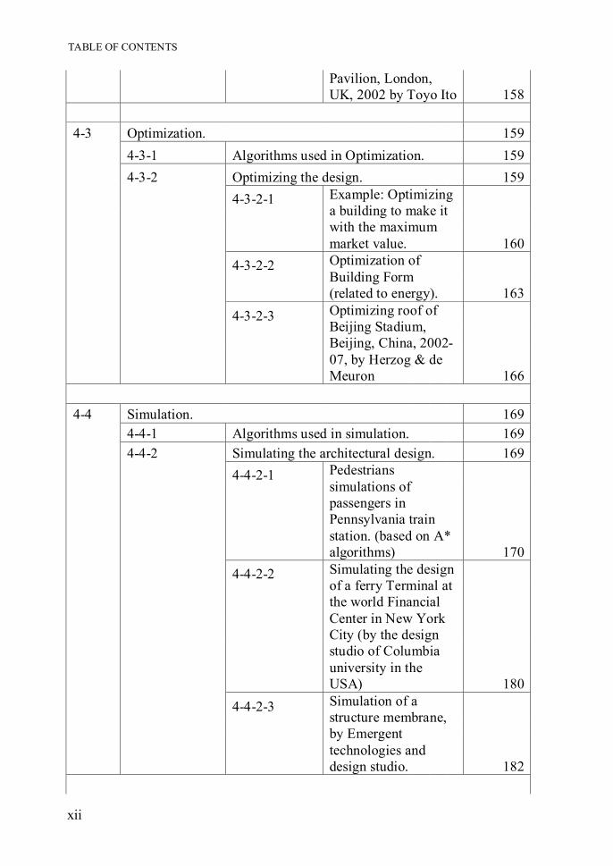
TABLE OF CONTENTS
xii
Pavilion, London, UK, 2002 by Toyo Ito 158
4-3 Optimization. 159 4-3-1 Algorithms used in Optimization. 159 4-3-2 Optimizing the design. 159 4-3-2-1 Example: Optimizing
a building to make it with the maximum market value.
160 4-3-2-2 Optimization of
Building Form (related to energy).
163 4-3-2-3 Optimizing roof of
Beijing Stadium, Beijing, China, 2002-07, by Herzog & de Meuron
166 4-4 Simulation. 169 4-4-1 Algorithms used in simulation. 169 4-4-2 Simulating the architectural design. 169 4-4-2-1 Pedestrians
simulations of passengers in Pennsylvania train station. (based on A* algorithms)
170 4-4-2-2 Simulating the design
of a ferry Terminal at the world Financial Center in New York City (by the design studio of Columbia university in the USA)
180 4-4-2-3 Simulation of a
structure membrane, by Emergent technologies and design studio.
182

TABLE OF CONTENTS
xiii
4-5 Transformation. 183 4-5-1 Algorithms used in Transformation. 183 4-5-2 Example for algorithms used in
transformation. Twin towers project by Emergence and design group.
184
Conclusion 191 PART III: ARCHITECTURE DESIGN BASED ON ALGORITHMS
193
CHAPTER 5: NEW METHODS IN ARCHITECTURAL DESIGN BASED ON ALGORITHMS
195
5-1 Introduction 195 5-2 Architectural design. 196 5-2-1 Function. 197 5-2-2 Form. 201 5-2-3 Economy 204 5-2-4 Time. 205 5-3
Using algorithms in designing an architectural project.
208 5-3-1 Generation. 211 5-3-1-1 Algorithm for
generating function.
214 5-3-1-2 Algorithm for
generating the form.
220 5-3-2 Permutations. 225 5-3-2-1 Algorithm for making
Permutations with respect to the aspects of function
227 5-3-2-2 Algorithm for making
Permutations with respect to the aspects of form .
230

TABLE OF CONTENTS
xiv
5-3-2-3 Algorithm for making Permutations with respect to the aspects of time
233 5-3-3 Optimizations. 235 5-3-3-1 Algorithm for
optimizing design with respect to the aspects of form.
236 5-3-3-2 Algorithm used for
optimizing design with respect to aspects of economy
238 5-3-4 Simulations. 241 5-3-4-1 Algorithm for
Simulating design with respect to the aspects of form.
242 5-3-5 Transformations. 245 5-3-6 The form of applying the previous
design method.
246 Conclusion 246
CHAPTER 6: APPLYING COMPUTATIONAL DESIGN METHODS
251
6-1 Generation (Voronoi algorithm). 254 6-1-1 Preparing for generating the voronoi
diagram.
255 6-1-2 Running the voronoi algorithm. 257 6-2 Permutations. 258 6-3 Optimization. 262 6-4 Final design. 263
CONCLUSIONS & RECOMMENDATIONS 273
REFERENCES 279
APPENDIX 285

LIST OF FIGURES
xv
LIST OF FIGURES
CHAPTER 1: INTRODUCTION TO ALGORITHMS Fig.1-1 Visualization of Turing-machine. 8 Fig.1-2 Algorithmic description of program 9 Fig.1-3 A simple flowchart algorithm for replacing a lamp. 13 CHAPTER 2: A BRIEF HISTORY OF ALGOTECTURE Fig.2-1 Applications of computers in architecture. 30 Fig.2-2 Linear graph diagram. 32 Fig.2-3 Generating a relationship graph from a relationship
matrix. 34 Fig.2-4 Layout alternatives and a dual graph representation. 35 Fig.2-5 Space allocation process: (a) grid (b) site (c) program (d)
relationship table (f) solution 37
Fig.2-6 Prototypes refinement rules select appropriate prototypes based on layout conditions.
38 Fig.2-7 Sample shape grammar. 40 Fig.2-8 Sample layout using the Shape grammar. 41 Fig.2-9 Various 3d forms generated with Shape grammars. 42 Fig.2-10 A generative theme. 43 Fig.2-11 Assigning height to 2d vector-base fractals. 44 Fig.2-12 The transformation process. 45 Fig.2-13 Various examples for transformation processes. 46 Fig.2-14 A process of morphing a box into a sphere. 46 Fig.2-15 Los Manantiales represented parametrically in a defined
matrix.
49

LIST OF FIGURES
xvi
CHAPTER 3: MAIN ALGORITHMS APPLIED IN CONTEMPORARY ARCHITECTURE Fig.3-1 Dividing a plane with a set of points (S) into a voronoi
diagram, the left picture shows the main points ( voronoi points or cells) and the circled points are the generated voronoi nodes. The right figure shows the voronoi diagram generated based on the voronoi points.
60 Fig.3-2 Main definitions concerning any Voronoi diagram. 61 Fig.3-3 Shows different voronoi diagrams due to variations in
the voronoi cells. 62 Fig.3-4 A simple Voronoi diagram with 5 points is modified by
moving one point. 62
Fig.3-5 Segments bisect the distances between cells. 63 Fig.3-6 Voronoi diagrams in biology and mineralogy of
formation principles, geometry, spatial effect and construction such as foams, sponges, and bone structures. 63
Fig.3-7 Different voronoi diagrams due to the variations in points distribution.
64 Fig.3-8 Methods of applying voronoi diagrams in architecture
by starting with certain points in a volume. 66
Fig.3-9 Right: the main layout. Left: the stages of generating the layout starting from the points to the final form.
66 Fig.3-10 The main façade of the performing arts center. 67 Fig.3-11 Various interior pictures represents the entrance and the
main hall. 67 Fig.3-12 The public plaza. constructed from the voronoi diagram. 67 Fig.3-13 Right: the main building reflects the use of voronoi
diagram, Left : using the envelope to .optimize the building performance. 68
Fig.3-14 Interior picture shows the surface constructed by a voronoi diagram.
68 Fig.3-15 Examples showing the shortest path between two points
selected by an A* algorithm. 69

LIST OF FIGURES
xvii
Fig.3-16 Steps done by an A* algorithm to compare paths from green node (upper right) to blue node (bottom left)
70
Fig.3-17 In the two pictures above, the red squares mark regions, where it's not possible to walk. The blue squares are the data copied and recalculated for the figure which is walking. To find out, which way is the best, some free squares are observed ("expanded" in technical terminology). Those squares are the yellow ones.
72 Fig.3-18 A* algorithm used in studying circulation in a certain
plan. 73 Fig.3-19 Using a stochastic search to distribute toys without any
overlaps in a certain area. 75 Fig.3-20 Office building façade based on stochastic search. 76 Fig.3-21 Various iterations for the façade. 77 Fig.3-22 Steps in the process of allocating program spaces
recursively within a 30 × 30 unit square site. 79
Fig.3-23 Library generated by the stochastic search algorithm. 79 Fig.3-24 Various generations for Koch Curve. 82 Fig.3-25 Various generations for Sierpinski triangle. 83 Fig.3-26 Various examples for using structure similar to nature
structures. 85 Fig.3-27 Final elevation for the skyscrapers. 86 Fig.3-28 Perspective shows the benefits for the inverted
skyscrapers (connected urban clusters ). 86 Fig.3-29 Structure System for one of the skyscrapers 87 Fig.3-30 Using L-systems to generate structure ( studying of
plans relative to structure) 87
Fig.3-31 Fakeplastic trees made from plastic PVC tubes. 88 Fig.3-32 Fakeplastic trees main form. 89 Fig.3-33 Cross-section showing the flow of water. 89 Fig.3-34 Sierpinski set was used in designing the translucent
alabaster cladding of the grand Egyptian museum's façade. 90
Fig.3-35 An Eight Neighborhood. 91 Fig.3-36 Basic cellular automata terminology. 91

LIST OF FIGURES
xviii
Fig.3-37 Game of life by John Conway 92 Fig.3-38 Game of life by John Conway ( Reproduction Phase). 93 Fig.3-39 Cellular automata as an LCD display wrapped around a
building (class project by N. Anderson for course GSD2311 taught by Kostas Terzidis in Fall 2005 at Harvard University)
95 Fig.3-40 CA adaptation into the design process of the housing
competition re-modeling. 96 Fig.3-41 The final outcome of the northern style housing
competition re-modeling Aomori/Japan 2001 using CA. 96 Fig.3-42 Variations in outcome. 97 Fig.3-43 Natural examples of SI include ant colonies, bird
flocking, and fish schooling. 98
Fig.3-44 Diagram of the swarm. Arrows represent each agent’s heading, dotted lines their closest neighbors.
99 Fig.3-45 Ant Colony as a natural swarm system. 99 Fig.3-46 Main items in creating a flocking algorithm 100 Fig.3-47 Paths of pedestrian exploration driven by space syntax
architectural concepts based on swarm intelligence.
102 Fig.3-48 Breaking of a corridor doorway into two helps in lane
formation and avoid door clogging and oscillation.
102 Fig.3-49 Simulation of a ship evacuation, using the tool
EXODUS based on swarm intelligence.
103 Fig.3-50 Evolutionary computation has its roots in computer
science and evolutionary biology.
104 Fig.3-51 Mapping genotypes in the search space to phenotypes in
the solution space.
105 Fig.3-52 The behavior of the crossover operator. The vertical line
shows the position of the random crossover point.
105 Fig.3-53 Four generations of evolving house designs using a
population size of four. Parents of the next generation are circled.
106 Fig.3-54 Classifications of evolutionary design by GAs. 106 Fig.3-55 Evolutionary optimization of a table. 107

LIST OF FIGURES
xix
Fig.3-56 Conceptual evolutionary design of a table. 107 Fig.3-57 Evolving artistic tables. 108 Fig.3-58 Generative evolutionary design of a table. 108 Fig.3-59 Generated chairs using 'CongGen' software. 109 Fig.3-60 The simplest genetic algorithm. 110 Fig.3-61 Two generations with their samples. 113 Fig.3-62 The animation was captured from 3125 spatial
arrangement solutions crossed four generations.
114 Fig.3-63 Natural cracks found in nature. 115 Fig.3-64 Steps for cracking a certain object. 116 Fig.3-65 Cracked objects by using the cracking the algorithm. 116 Fig.3-66 Oscillatory packing. 117 Fig.3-67 Various forms generated by packing. 118 Fig.3-68 Spiral as a path for objects. 119 Fig.3-69 Parameters for generating a spiral. 119 Fig.3-70 Examples for spirals generated by the algorithm. 120 Fig.3-71 Various types for weaving. 121 Fig.3-72 Forms generated by weaving algorithm. 122 CHAPTER 4: APPLICATIONS OF ALGORITHMS IN ARCHITECTURE.
Fig.4-1 Exterior perspective for the final form. 132 Fig.4-2 Automaton cells generation (1-6). 133 Fig.4-3 Automaton cells generation (7-10). 134 Fig.4-4 The previous generated Automaton cells. 134 Fig.4-5 Connecting the cellular cells together. 135 Fig.4-6 Connecting the cellular cells together. 135 Fig.4-7 Generating the voronoi diagram from the cellular cells. 135 Fig.4-8 Smoothing the voronoi diagram. 136 Fig.4-9 Smoothing the voronoi diagram. 136 Fig.4-10 Successive sections show the generated voronoi 136

LIST OF FIGURES
xx
diagram. Fig.4-11 Section shows the generated voronoi diagram. 137 Fig.4-12 Final form shows the generated smoothed voronoi. 137 Fig.4-13 Final form shows the generated unit and interior shot. 137 Fig.4-14 Final form shows the generated unit and interior shot. 137 Fig.4-15 Escalator surrounded by the voronoi diagram. 138 Fig.4-16 Specifying the points in space to generate the form
based on Voronoi diagram.
139 Fig.4-17 Specifying the points in space to generate the form
based on Voronoi diagram.
139 Fig.4-18 Studying the form relative to the context. 139 Fig.4-19 Smoothing the outline of the tower. 139 Fig.4-20 Studying the generated spaces. 140 Fig.4-21 Studying the generated spaces. 140 Fig.4-22 Clusters generated by voronoi cells resembles the
relation of bones to organs.
140 Fig.4-23 Final form for the building. 141 Fig.4-24 Main Façade for the building. 141 Fig.4-25 Generation of a Trimino.( Each generated shape is
accompanied by its genotype and phenotype).
145 Fig.4-26 Some Examples of Conjoining Two Polyminoes. 145 Fig.4-27 Crossover at Room Level; (a) initial rooms R1 and R2
generated from unit square cell U1, (b) crossover at site 4.
148 Fig.4-28 Zone Crossover; (a) rooms and initial zones, Z1 and Z2,
(b) crossover at Site 2.
148 Fig.4-29 Results of Living Room Generation after the 17th
generation ( The left side shows the solutions selected by the architect).
149 Fig.4-30 Results of Living Zone Generation. 150 Fig.4-31 Results of Bed and Living Zones Generation. 150 Fig.4-32 Results of House Generation. 151

LIST OF FIGURES
xxi
Fig.4-33 Main steps in generating the form. 152 Fig.4-34 Volume aggregation algorithm. 153 Fig.4-35 Volume division algorithm. 154 Fig.4-36 Selection of a variant. 155 Fig.4-37 Final form for the project. 156 Fig.4-38 Using algorithm based on mathematical equations to
generate the mesh.
157 Fig.4-39 Final roof as generated by the algorithm. 157 Fig.4-40 Permutations for the form of the gallery based on special
algorithm.
158 Fig.4-41 Final form for the gallery. 158 Fig.4-42 The algorithm ( Based on (GA) used in optimizing the
building.
160 Fig.4-43 Steps for generating the design. 161 Fig.4-44 A building variant is assembled out of pre-defined
apartment types based on a series of construction rules.
162 Fig.4-45 Number of iterations relative to the value, with examples
to show the form of the buildings after number of iterations.
162 Fig.4-46 The construction rule parameters are altered recursively
with the goal of increasing the building value.
163 Fig.4-47 Two views are shown for each solution, from the
southwest and northeast, and for every solution the values for energy are stated relative to the lighting and heating factors.
164 Fig.4-48 Solution 1 represents the best building shape in terms of
heating. Solution 6 is the best building shape in terms of lighting. The other images represent intermediate solutions.
165 Fig.4-49 A certain algorithm is used to rotate the beams to
generate forms and iterates until the resultant meet the architect needs.
167 Fig.4-50 Steps of optimizing the surface of the stadium by

LIST OF FIGURES
xxii
minimizing the in-between spaces (colored red). 168 Fig.4-51 Hierarchical World Model. 171 Fig.4-52 Perception maps : Stationary, and Mobile. 173 Fig.4-53 Visual Sensing. Left: Sensing stationary objects by
examining map entries along rasterized eye rays. Right: Sensing mobile objects by examining (color-coded) tiers of the sensing fan.
174 Fig.4-54 Path maps : Grid, and Quadtree. 176 Fig.4-55 Constructing a quadtree map. 177 Fig.4-56 Visualization of the quad-tree map of the concourse’s
upper level in the Penn Station environment model. The white quads denote ground nodes and the blue ones denote obstacles. The green circle is the start point and the orange circle is the target.
179 Fig.4-57 The search space is color coded with the distance
variable values increasing from green to orange.
179 Fig.4-58 Main Arcade. 180 Fig.4-59 Train Platform. 180 Fig.4-60 Main steps for simulating the design of a ferry terminal. 180 Fig.4-61 Ferry Terminal plans. 181 Fig.4-62 Evening passenger flow. 181 Fig.4-63 The heat maps of three building variants that were
tested. 182 Fig.4-64 Geometry of the membrane-tensegrity structure, and
Dynamic Relaxation process.
183 Fig.4-65 Digital stress-driven form evolution of membrane
tensegrity structures.
183 Fig.4-66 Cross-Section showing the structure for the towers. 185 Fig.4-67 Structure system composed form a group Helical beams
combined together.
186 Fig.4-68 The skin of a custard apple. 187 Fig.4-69 Skin-panel geometry: algorithmic differentiation. 189

LIST OF FIGURES
xxiii
CHAPTER 5: NEW METHODS IN ARCHITECTURAL DESIGN BASED ON ALGORITHMS
Fig.5-1 People grouping according to thier performance. 197 Fig.5-2 Activity Grouping: separated or combined. 197 Fig.5-3 Service Grouping: separated or combined. 198 Fig.5-4 Hierarchy in spaces, authority,..etc, according to
function. 198 Fig.5-5 Priority according to users, position,..etc. 198 Fig.5-6 Variations in security controls according to situations. 199 Fig.5-7 Circulation of people in a museum. 199 Fig.5-8 Separating circulation between different kinds of users. 199 Fig.5-9 Main atriums could be an example for a mixed flow . 200 Fig.5-10 Relationship between spaces must be studied (either
direct or indirect). 200 Fig.5-11 Determine the spaces that should communicate with
others. 200 Fig.5-12 Studying the density for combining the masses of design
is essential. 201
Fig.5-13 Environmental controls by studying the climate and decide how to make the atmosphere more comfort for people. 201
Fig.5-14 Studying the relations with neighbors. 202 Fig.5-15 Studying spaces according to home base. 202 Fig.5-16 Orienting the building according to the function needs. 203 Fig.5-17 Access points should be studied. 203 Fig.5-18 How will the building look like? 203 Fig.5-19 Studying economical ideas to make the design meets the
available funds.
204 Fig.5-20 Studying how the energy can be conserved. 205 Fig.5-21 Determine if the design meets the requirements or not. 205 Fig.5-22 Studying the methods to make the design flexible. 206 Fig.5-23 Studying the capability to divide the project into phases. 207 Fig.5-24 Steps for running a simple Interactive genetic algorithm

LIST OF FIGURES
xxiv
to generate zoning (on the left side algorithmic steps, on the right side architectural output)
215 Fig.5-25 Final zoning generated by the Interactive genetic
algorithm. 217 Fig.5-26 Process of generating plans in each zone. 218 Fig.5-27 Steps for running a simple Interactive genetic algorithm
to generate Plan in each zone (on the left side algorithmic steps, on the right side architectural output)
219 Fig.5-28 Final plan as generated form the previous algorithm. 220 Fig.5-29 Steps for running a simple Voronoi algorithm to
generate the main form (on the left side algorithmic steps, on the right side architectural output).
222 Fig.5-30 Final form generated from the voronoi algorithm.
225 Fig.5-31 Steps for adding and studying circulation for the design
by using a* algorithm. 228
Fig.5-32 Algorithm used for making permutations for a certain generated form (algorithm for generation + Iteration) 231
Fig.5-33 Steps for studying permutations of a plan to study the adaptability by using an interactive genetic algorithm (on the left side algorithmic steps, on the right side architectural output).
234 Fig.5-34 Genetic algorithm runs to optimize building with respect
to environment. 237
Fig.5-35 Genetic algorithm runs to optimize building with respect to value (on the left side algorithmic steps, on the right side architectural output).
239 Fig.5-36 Swarm algorithm runs to simulate the building with
respect to safety precautions (on the left side algorithmic steps, on the right side architectural output).
243
CHAPTER 6: APPLYING COMPUTATIONAL DESIGN METHODS.
Fig.6-1 The design matrix for the Museum. 254 Fig.6-2 Main zones in the museum. 254

LIST OF FIGURES
xxv
Fig.6-3 The main plan for the museum as generated from the zoning step. 255
Fig.6-4 Main spaces represented as spheres. 256
Fig.6-5 Centers of spheres are the main points for generating the voronoi algorithm. 256
Fig.6-6 Generated form for the exhibition part consists of: - Units represent main spaces of galleries - Other units as skylight source.
257 Fig.6-7 Generated main gallery spaces as voronoi units. 258 Fig.6-8 The form generated by the voronoi algorithm. 258 Fig.6-9 Offspring for the design alternatives .
259 Fig.6-10 Offspring for the design alternatives.
260 Fig.6-11 Offspring for the design alternatives. The selected form
is surrounded by a box. 261 Fig.6-12 Parameters represent the dimensions of the column.
262 Fig.6-13 Simple steps represent the optimization algorithm.
263 Fig.6-14 Final plan for the project. 264 Fig.6-15 Section in the exhibition part shows the voronoi cells.
264 Fig.6-16 Final form for the exhibition zone. 265 Fig.6-17 Final form for the exhibition zone. 265 Fig.6-18 Final form for the exhibition.
267 Fig.6-19 Final form for the exhibition. 269 Fig.6-20 Final form for the exhibition. 271

LIST OF TABLES
xxvi

LIST OF TABLES
xxvii
LIST OF TABLES
CHAPTER 2: A BRIEF HISTORY OF ALGOTECTURE Tab.2-1 Geometric measures of node in minimum-path
graph. 33
CHAPTER 3: MAIN ALGORITHMS APPLIED IN CONTEMPORARY ARCHITECTURE Tab.3-1 Support for algorithmic form generation. 58 CHAPTER 4: APPLICATIONS OF ALGORITHMS IN ARCHITECTURE.
Tab.4-1 GA and exhaustive searches for optimal control
schedule, as a function of population size, number of generations, and weighting function. The weighting function now includes a weight on electricity demand. 165
Tab.4-2 Stationary and mobile objects. 173 CHAPTER 5: NEW METHODS IN ARCHITECTURAL DESIGN BASED ON ALGORITHMS
Tab.5-1 The design matrix showing the new design method
based on algorithms. 208 Tab.5-2a Aspects for designing function. 208 Tab.5-2b Aspects for designing form. 208 Tab.5-2c Aspects for Economical studies. 208 Tab.5-2d Aspects for designing with respect to time. 209

LIST OF TABLES
xxviii
Tab.5-2e Matrix for applying algorithms to design architectural design. 192
Tab.5-3 Algorithms that can be used to generate each aspect in design. 212
Tab.5-3a Algorithms that can be used to generate each aspect in design. 212
Tab.5-3b Algorithms that can be used to generate each aspect in design. 212
Tab.5-3c Algorithms that can be used to generate each aspect in design. 212
Tab.5-3d Algorithms that can be used to generate each aspect in design. 213
Tab.5-4 Explaining the algorithmic steps for running an Interactive Genetic Algorithm to generate zoning. 216
Tab.5-5 Explaining the previous voronoi diagram. 224 Tab.5.6 Algorithms that can be used to permutate each
aspect in design. 225 Tab.5.6a Algorithms that can be used to permutate each
aspect in design. 226 Tab.5.6b Algorithms that can be used to permutate each
aspect in design. 226 Tab.5.6c Algorithms that can be used to permutate each
aspect in design. 226 Tab.5.6d Algorithms that can be used to permutate each
aspect in design. 227 Tab.5.7 Algorithm that can be used to permutate circulation
in design. 230 Tab.5.8 Making permutations by using a voronoi algorithm
and iterations.
233 Tab.5.9 Algorithms that can be used to optimize each aspect
in design.
235 Tab.5.9a Algorithms that can be used to optimize each aspect
in design.
235 Tab.5.9b Algorithms that can be used to optimize each aspect
in design.
235 Tab.5.9c Algorithms that can be used to optimize each aspect
in design.
236

LIST OF TABLES
xxix
Tab.5.9d Algorithms that can be used to optimize each aspect in design.
236
Tab.5.10 Optimizing a design to reach best environmental performance for the building.
238
Tab.5.11 Making optimization to reach the maximum market value for the building.
241
Tab.5.12 Algorithms that can be used to Simulate each aspect in design.
241
Tab.5.12a Algorithms that can be used to Simulate each aspect in design.
242
Tab.5.12b Algorithms that can be used to Simulate each aspect in design.
242
Tab.5.12c Algorithms that can be used to Simulate each aspect in design.
242
Tab.5.12d Algorithms that can be used to Simulate each aspect in design.
242
Tab.5.13 Simulating a design to test the safety precautions. 244 Tab.5.14 Algorithms that can be used to transform each
aspect in design. 245 Tab.5.14a Algorithms that can be used to transform each
aspect in design. 245 Tab.5.14b Algorithms that can be used to transform each
aspect in design. 245 Tab.5.14c Algorithms that can be used to transform each
aspect in design. 246 Tab.5.14d Algorithms that can be used to transform each
aspect in design. 246

GLOSSARY
xxx

GLOSSARY
xxxi
GLOSSARY
A* (pronounced “A star”) is a best-first, graph search algorithm that finds the least-cost path from a given initial node to one goal node (out of one or more possible goals)
Algorithm: is a well-ordered collection of unambiguous and effectively computable operations that when executed produces a result and halts in a finite amount of time. Algotecture is a term to denote the use of algorithms in architecture. This term differs from the popular terms CAD or computer graphics in the sense that algorithms are not necessarily dependent on computers whereas the former are, at least, by definition. This distinction is very important as it liberates, excludes, and disassociates the mathematical and logical processes used for addressing a problem from the machine that facilitates the implementation of those processes. Such a use involves the articulation of a strategy for solving problems whose target is known, as well as to address problems whose target cannot be defined. Allele is one member of a pair or series of different forms of a gene. Usually alleles are coding sequences, but sometimes the term is used to refer to a non-coding sequence. An individual's genotype for that gene is the set of alleles it happens to possess. In diploid organisms (two copies of each chromosome) including humans, two alleles make up the individual's genotype.
Artificial intelligence (AI) is a branch of computer science concerned with the problem of how to simulate human intelligence. AI is as old as the invention of the first computer, or, to be more precise, of the first counting machine.
Artificial intelligence is a branch of computer science concerned with the problem of how to simulate human intelligence. AI is as old as the invention of the first computer, or, to be more precise, of the first counting machine.

GLOSSARY
xxxii
cellular automaton (plural: cellular automata) is a discrete model studied in computability theory, mathematics, theoretical biology and Microstructure Modeling. It consists of a regular grid of cells, each in one of a finite number of states. The grid can be in any finite number of dimensions. Time is also discrete, and the state of a cell at time t is a function of the states of a finite number of cells (called its neighborhood) at time t
−1.
A chromosome (also sometimes called a genome) in a genetic algorithm is a set of parameters which define a proposed solution to the problem that the genetic algorithm is trying to solve. The chromosome is often represented as a simple string, although a wide variety of other data structures are also used.
A Crossover ( in a genetic algorithm) is a genetic operator used to vary the programming of a chromosome or chromosomes from one generation to the next. It is analogous to reproduction and biological crossover, upon which genetic algorithms are based.
Embedded programming language A Fitness function is a particular type of objective function that quantifies the optimality of a solution (that is, a chromosome) in a genetic algorithm so that that particular chromosome may be ranked against all the other chromosomes. Optimal chromosomes, or at least chromosomes which are more optimal, are allowed to breed and mix their datasets by any of several techniques, producing a new generation that will (hopefully) be even better.
Fractal is an object or quantity that displays self-similarity on all scales with non-integer dimensions. The object need not exhibit exactly the same structure at all scales, but the same “type” of structures must appear on all scales.
Genetic algorithms attempt to find solutions to problems by mimicking biological evolutionary processes, with a cycle of random mutations yielding successive generations of "solutions". Thus, they emulate reproduction and "survival of the fittest". In genetic programming, this approach is extended to algorithms, by regarding the algorithm itself as a "solution" to a problem.
The Genotype is the genetic constitution of a cell, an organism, or an individual (i.e. the specific allele makeup of the individual) usually with reference to a specific character under consideration.

GLOSSARY
xxxiii
Heuristic is an adjective for methods that help in problem solving in turn leading to learning and discovery. These methods in most cases employ experimentation and trial and error techniques. A heuristic method is particularly used to rapidly come to a solution that is reasonably close to the best possible answer, or 'optimal solution'
A High-level programming language is one which has a relatively high level of abstraction, and manipulates conceptual structures in a semi-naturalistic manner. A low-level programming language is one like assembly language that contains rudimentary microprocessor commands.
Interactive genetic algorithm (IGA) is defined as a genetic algorithm that uses human evaluation. These algorithms belong to a more general category of Interactive evolutionary computation. The main application of these techniques include domains where it is hard or impossible to design a computational fitness function, for example, evolving images, music, various artistic designs and forms to fit a user's aesthetic preferences. Interactive computation methods can use different representations, both linear (as in traditional genetic algorithms) and tree-like ones (as in genetic programming).
Lindenmayer System is a formal grammar that was initially conceived as a theory of plant growth. L-Systems can generate complex forms with relatively few simple rules. L-Systems consist of two parts: a generative and an interpretative process. The main concept of the generative process is string rewriting, in which the letters that comprise an initial string are replaced by other letters according to pre-defined rules. The replaced letters form a new generation of string which is then subject to the established replacement rules. This string rewriting process is usually repeated for several generations.
Parametric design is turning design into a set of principles encoded as a sequence of parametric equations. The equations are used to express certain quantities as explicit functions of a number of variables. By changing any parameter in the equation new forms and new shapes could be generated. The parameters are not just numbers relating to Cartesian geometry, they could be performance based criteria such as light levels or structural load resistance, or even a set of aesthetic principles.

GLOSSARY
xxxiv
A Phenotype is any observable characteristic or trait of an organism: such as its morphology, development, biochemical or physiological properties, or behavior. Pseudo code (derived from pseudo and code) is a compact and informal high-level description of a computer programming algorithm that uses the structural conventions of programming languages, but omits detailed subroutines, variable declarations or language-specific syntax. The programming language is augmented with natural language descriptions of the details, where convenient.
Rasterization or Rasterisation is the task of taking an image described in a vector graphics format (shapes) and converting it into a raster image (pixels or dots) for output on a video display or printer, or for storage in a bitmap file format.The term rasterization can in general be applied to any process by which vector information can be converted into a raster format. In normal usage, the term refers to the popular rendering algorithm for displaying three-dimensional shapes on a computer.
Recursion or iteration: A recursive algorithm is one that invokes (makes reference to) itself repeatedly until a certain condition matches, which is a method common to functional programming. Iterative algorithms use repetitive constructs like loops and sometimes additional data structures like stacks to solve the given problems. Some problems are naturally suited for one implementation or the other.
A Scripting language, script language or extension language is a programming language that allows some control of a single or many software application(s). Languages chosen for scripting purposes are often much higher-level than the language used by the host application. "Scripts" are often treated as distinct from "programs", which execute independently from any other application. At the same time they are distinct from the core code of the application, which is usually written in a different language, and by being accessible to the end-user they enable the behavior of the application to be adapted to the user's needs. Scripts are often, but not always, interpreted from the source code or "semi-compiled" to bytecode which is interpreted, unlike the applications they are associated with, which are traditionally compiled to native machine code for the system on which they run. Scripting languages are nearly always embedded in the application with which they are associated.

GLOSSARY
xxxv
Stochastic search is defined as a random search in space until a given condition is met. Stochastic optimization methods are optimization algorithms which incorporate probabilistic (random) elements, either in the problem data (the objective function, the constraints, etc.), or in the algorithm itself (through random parameter values, random choices, etc.), or in both
Swarm intelligence (SI) is an artificial intelligence based on the collective behavior of decentralized, self-organized systems . SI systems are typically made up of a population of simple agents interacting locally with one another and with their environment. Although there is no centralized control structure dictating how individual agents should behave, local interactions between such agents lead to the emergence of global behavior. Natural examples of SI include ant colonies, bird flocking, animal herding, bacterial growth, and fish schooling
Transformation or morphing is a process in which an object changes its form gradually in order to obtain another form. The operation of transformation consists basically of the selection of two objects and the assignment of n, the number of in-between steps. The first object then transforms into the second in n steps.
Turing machines: are extremely basic abstract symbol-manipulating devices which, despite their simplicity, can be adapted to simulate the logic of any computer that could possibly be constructed. They were described in 1936 by Alan Turing. A Turing machine consists of an infinite one-dimensional tape divided into cells, a movable read-write head with a specified starting position, and a table of transition rules. Each cell of the tape contains one symbol, either 0 or 1, and the head can move along the tape to scan one cell at a time and perform three different activities: • READ: read the content of the cell, • WRITE: change the content into the opposite, and • MOVE: advance to the next cell to the right or left along the tape. A table of transition rules serves as the program for the machine.

GLOSSARY
xxxvi
Voronoi diagram is the partitioning of a plane with points into convex polygons such that each polygon contains exactly one generating point and every point in a given polygon is closer to its generating point than to any other. A Voronoi diagram is sometimes also known as a Dirichlet tessellation. The cells are called Dirichlet regions, Thiessen polytopes, or voronoi polygon.
Search algorithm, broadly speaking, is an algorithm that takes a problem as input and returns a solution to the problem, usually after evaluating a number of possible solutions. Most of the algorithms studied by computer scientists that solve problems are kinds of search algorithms. The set of all possible solutions to a problem is called the search space.

GLOSSARY
i
THESIS STRUCTURE
Results and Recommendations
Part I: ALGORITHMS AND HISTORY OF ALGOTECTURE.
Chapter 1: INTRODUCTION TO ALGORITHMS.
Chapter 2: A BRIEF HISTORY OF ALGOTECTURE.
Chapter 3: MAIN ALGORITHMS APPLIED IN CONTEMPORARY ARCHITECTURE.
Part II: IMPLEMENTED ALGORITHMS IN CONTEMPORARY ARCHITECTURE.
Chapter 4: APPLICATIONS OF ALGORITHMS IN ARCHITECTURE.
Chapter 5: NEW METHODS IN ARCHITECTURAL DESIGN BASED ON ALGORITHMS.
Part III: ARCHITECTURAL DESIGN BASED ON ALGORITHMS.
Chapter 6: APPLYING COMPUTATIONAL DESIGN METHODS.

PART I : ALGORITHMS AND HISTORY CHAPTER 1: INTRODUCTION TO ALGORITHMS. OF ALGOTECTURE.
1
PART I
ALGORITHMS AND HISTORY OF ALGOTECTURE

CHAPTER 1: INTRODUCTION TO ALGORITHMS. PART I : ALGORITHMS AND HISTORY OF ALGOTECTURE.
2

PART I : ALGORITHMS AND HISTORY CHAPTER 1: INTRODUCTION TO ALGORITHMS. OF ALGOTECTURE.
3
CHAPTER 1: INTRODUCTION TO ALGORITHMS

CHAPTER 1: INTRODUCTION TO ALGORITHMS. PART I : ALGORITHMS AND HISTORY OF ALGOTECTURE.
4

PART I : ALGORITHMS AND HISTORY CHAPTER 1: INTRODUCTION TO ALGORITHMS. OF ALGOTECTURE.
5
CHAPTER 1:
INTRODUCTION TO ALGORITHMS
1-1 Definition.
An algorithm is a well-ordered collection of unambiguous and effectively computable operations that when executed produces a result and halts in a finite amount of time1.
In mathematics, computing, linguistics, and related disciplines, an algorithm is a finite list of well-defined instructions for accomplishing tasks that, given an initial state, will terminate in a defined end-state.
1-2 Explanation
Algorithms can be explained as follows:
a. It is a process of addressing a problem in a finite number of steps. It is an articulation of either a strategic plan for solving a known problem or a stochastic search towards possible solutions to a partially known problem. In doing so, it serves as a codification of the problem through a series of finite, consistent, and rational steps.
b. While most algorithms are designed with a specific solution
in mind to a problem, there are some problems whose solution is unknown, vague, or ill-defined. In the latter case, algorithms become the means for exploring possible paths that may lead to potential solutions.
1 Schneider, M. and J. Gersting (1995), An Invitation to Computer Science, West Publishing Company, New York, NY, p. 9.

CHAPTER 1: INTRODUCTION TO ALGORITHMS. PART I : ALGORITHMS AND HISTORY OF ALGOTECTURE.
6
c. Theoretically, as long as a problem can be defined in logical
terms, a solution may be produced that will address the problem’s demands. An algorithm is a linguistic expression of the problem and is composed of linguistic elements and operations arranged into spelling, and grammatically and syntactically correct statements. The linguistic articulation serves the purpose not only to describe the problem’s steps but also to communicate the solution to another agent for further processing. In the world of computers, that agent is the computer itself.
d. An algorithm can be seen as a mediator between the human
mind and the computer’s processing power. This ability of an algorithm to serve as a translator can be interpreted as bi-directional: either as a dictation to the computer how to go about solving the problem, or as a reflection of a human thought into the form of an algorithm1.
e. Traditionally, algorithms were used as mathematical or
logical mechanisms for resolving practical problems. With the invention of the computer, algorithms became frameworks for implementing problems to be carried out by computers2.
f. An algorithm is a set of instructions given by a human to be
performed by a computer. Therefore, an algorithm can describe either the way a problem is to be addressed as if it would be resolved by a human or the way it should be addressed to be understood by a computer (the notion of “understanding” here refers to the capacity the computer has to process information given by a human and not to its conscious interpretation of that information).
g. An algorithm becomes a rationalized version of human
thinking. As such it may be characterized as being precise, 1 Terzidis, Kostas (2006). Algorithmic Archtecture. Architectural Press, Elsevier. 2 Ibid.
PART I : ALGORITHMS AND HISTORY CHAPTER 1: INTRODUCTION TO ALGORITHMS. OF ALGOTECTURE.
7
definite, and logical, but at the same time may also lack certain unique qualities of human expression such as vagueness, ambiguity, or ambivalence1.
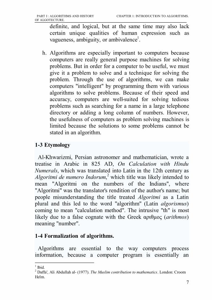
h. Algorithms are especially important to computers because
computers are really general purpose machines for solving problems. But in order for a computer to be useful, we must give it a problem to solve and a technique for solving the problem. Through the use of algorithms, we can make computers "intelligent" by programming them with various algorithms to solve problems. Because of their speed and accuracy, computers are well-suited for solving tedious problems such as searching for a name in a large telephone directory or adding a long column of numbers. However, the usefulness of computers as problem solving machines is limited because the solutions to some problems cannot be stated in an algorithm.
1-3 Etymology
Al-Khwarizmi, Persian astronomer and mathematician, wrote a treatise in Arabic in 825 AD, On Calculation with Hindu Numerals, which was translated into Latin in the 12th century as Algoritmi de numero Indorum,2 which title was likely intended to mean "Algoritmi on the numbers of the Indians", where "Algoritmi" was the translator's rendition of the author's name; but people misunderstanding the title treated Algoritmi as a Latin plural and this led to the word "algorithm" (Latin algorismus) coming to mean "calculation method". The intrusive "th" is most likely due to a false cognate with the Greek αριθμος (arithmos) meaning "number".
1-4 Formalization of algorithms.
Algorithms are essential to the way computers process information, because a computer program is essentially an 1 Ibid. 2 Daffa', Ali Abdullah al- (1977). The Muslim contribution to mathematics. London: Croom Helm.

CHAPTER 1: INTRODUCTION TO ALGORITHMS. PART I : ALGORITHMS AND HISTORY OF ALGOTECTURE.
8
algorithm that tells the computer what specific steps to perform (in what specific order) in order to carry out a specified task, such as calculating employees’ paychecks or printing students’ report cards. Thus, an algorithm can be considered to be any sequence of operations that can be performed by a Turing-complete system1. Fig. 1.1.
"an algorithm is a computational process defined by a Turing machine."2
Figure 1-1 Visualization of Turing-machine.
A table of transition rules serves as the program for the machine. Each such rule is a quadruple <stateactual,symbol,action,statenext > which means if the machine is in stateactual and the current cell contains symbol then take action MOVE or WRITE and move into statenext. Thus, the transition rules are labeled as staten and the
1 Turing machines : are extremely basic abstract symbol-manipulating devices which, despite their simplicity, can be adapted to simulate the logic of any computer that could possibly be constructed. They were described in 1936 by Alan Turing. A Turing machine consists of an infinite one-dimensional tape divided into cells, a movable read-write head with a specified starting position, and a table of transition rules. Each cell of the tape contains one symbol, either 0 or 1, and the head can move along the tape to scan one cell at a time and perform three different activities: READ: read the content of the cell, WRITE: change the content into the opposite, andMOVE: advance to the next cell to the right or left along the tape.A table of transition rules serves as the program for the machine. 2 Yuri Gurevich, Sequential Abstract State Machines Capture Sequential Algorithms, ACM Transactions on Computational Logic, Vol 1, no 1 (July 2000), pages 77–111.

PART I : ALGORITHMS AND HISTORY CHAPTER 1: INTRODUCTION TO ALGORITHMS. OF ALGOTECTURE.
9
execution of the program consists of the successive transition between one state and another. Furthermore, the program terminates if it reaches a situation in which there is not exactly one transition rule specified for execution1. Fig. 1.2
Figure 1-2 algorithmic description of program
Typically, when an algorithm is associated with processing information, data are read from an input source or device, written to an output sink or device, and/or stored for further processing. Stored data are regarded as part of the internal state of the entity performing the algorithm. In practice, the state is stored in a data structure, but an algorithm requires the internal data only for specific operation sets called abstract data types.
For any such computational process, the algorithm must be rigorously defined: specified in the way it applies in all possible circumstances that could arise. That is, any conditional steps must be systematically dealt with, case-by-case; the criteria for each case must be clear (and computable).
Because an algorithm is a precise list of precise steps, the order of computation will almost always be critical to the functioning of the algorithm. Instructions are usually assumed to be listed explicitly, and are described as starting 'from the top' and going 'down to the bottom', an idea that is described more formally by flow of control.
1 Barker-Plummer, David: Turing Machines, in Edward N. Zalta (ed.): The Stanford Encyclopedia of Philosophy (Spring 2005 Edition), http://plato.stanford.edu/archives/ spr2005/entries/turing-machine/

CHAPTER 1: INTRODUCTION TO ALGORITHMS. PART I : ALGORITHMS AND HISTORY OF ALGOTECTURE.
10
1-5 Expressing algorithms.
Algorithms can be expressed in many kinds of notation, including natural languages, pseudocode, flowcharts, and programming languages and can be explained in details as follows1:-
1-5-1 Natural language:-
In the philosophy of language, a natural language (or ordinary language) is a language that is spoken, written, or signed (visually or tactilely) by humans for general-purpose communication, which is distinguished from formal languages (such as computer-programming languages or the "languages" used in the study of formal logic, especially mathematical logic).
When writing algorithms, several choices are available of how the algorithm will be specified. One option is to write the algorithm using plain English. Although plain English may seem like a good way to write an algorithm, it has some problems that make it a poor choice. First, plain English is too wordy. When the algorithm is written in plain English, it must include many words that contribute to correct grammar or style that have nothing to do to help to communicate the algorithm. Second, plain English is too ambiguous. Often an English sentence can be interpreted in many different ways. Remember that the definition of an algorithm requires that each operation must be unambiguous.
Natural language expressions of algorithms tend to be verbose and ambiguous, and are rarely used for complex or technical algorithms.
For example an Algorithm written in plain English can be written in one of the two ways as follows (replace the oil of your):-
- First way: First, place the oil pan underneath the oil plug of your car. Next, unscrew the oil plug and drain the oil. Now, replace the
1 Sipser, Michael (2006). Introduction to the Theory of Computation. PWS Publishing Company.p.157

PART I : ALGORITHMS AND HISTORY CHAPTER 1: INTRODUCTION TO ALGORITHMS. OF ALGOTECTURE.
11
oil plug. Once the old oil is drained, remove the oil cap from the engine and pour in 4 quarts of oil. Finally, replace the oil cap on the engine. - Second way:
1. Place the oil pan underneath the oil plug of your car. 2. Unscrew the oil plug. 3. Drain oil. 4. Replace the oil plug. 5. Remove the oil cap from the engine. 6. Pour in 4 quarts of oil. 7. Place the oil pan underneath the oil plug of your car. 8. Unscrew the oil plug. 9. Drain oil. 10. Replace the oil plug. 11. Remove the oil cap from the engine. 12. Pour in 4 quarts of oil. 13. Replace the oil cap.
Each of these examples is an algorithm, a set of instructions for solving a problem. Once the algorithm is created there is no need to think about the principles on which the algorithm is based. For example, once you have the directions to John's house, you do not need to look at a map to decide where to make the next turn. The intelligence needed to find the correct route is contained in the algorithm. All you have to do is follow the directions. This means that algorithms are a way of capturing intelligence and sharing it with others. Once you have encoded the necessary intelligence to solve a problem in an algorithm, many people can use your algorithm without needing to become experts in a particular field.
1-5-2 Pseudo code:-

CHAPTER 1: INTRODUCTION TO ALGORITHMS. PART I : ALGORITHMS AND HISTORY OF ALGOTECTURE.
12
Pseudo1 code (derived from pseudo and code) is a compact and informal high-level description of a computer programming algorithm that uses the structural conventions of programming languages, but omits detailed subroutines, variable declarations or language-specific syntax. The programming language is augmented with natural language descriptions of the details, where convenient.
Pseudocode is structured way to express algorithms that avoid many of the ambiguities common in natural language statements, while remaining independent of a particular implementation language.
An example of how pseudocode differs from regular code is below.
Regular code (written in PHP):
<?php if (is_valid($cc_number)) { execute_transaction($cc_number, $order); } else { show_failure(); } ?>
Pseudocode:
if credit card number is valid execute transaction based on number and order else show a generic failure message
1 In common parlance, the prefix pseudo is used to mark something as false, fraudulent, or pretending to be something it is not, as in pseudoscience or pseudophilosophy. It also identifies something as superficially resembling the original subject; a pseudo pod resembles a foot, and pseudorandom numbers simulate numbers generated by truly random events, but are in fact produced by an algorithm.
PART I : ALGORITHMS AND HISTORY CHAPTER 1: INTRODUCTION TO ALGORITHMS. OF ALGOTECTURE.
13
end if
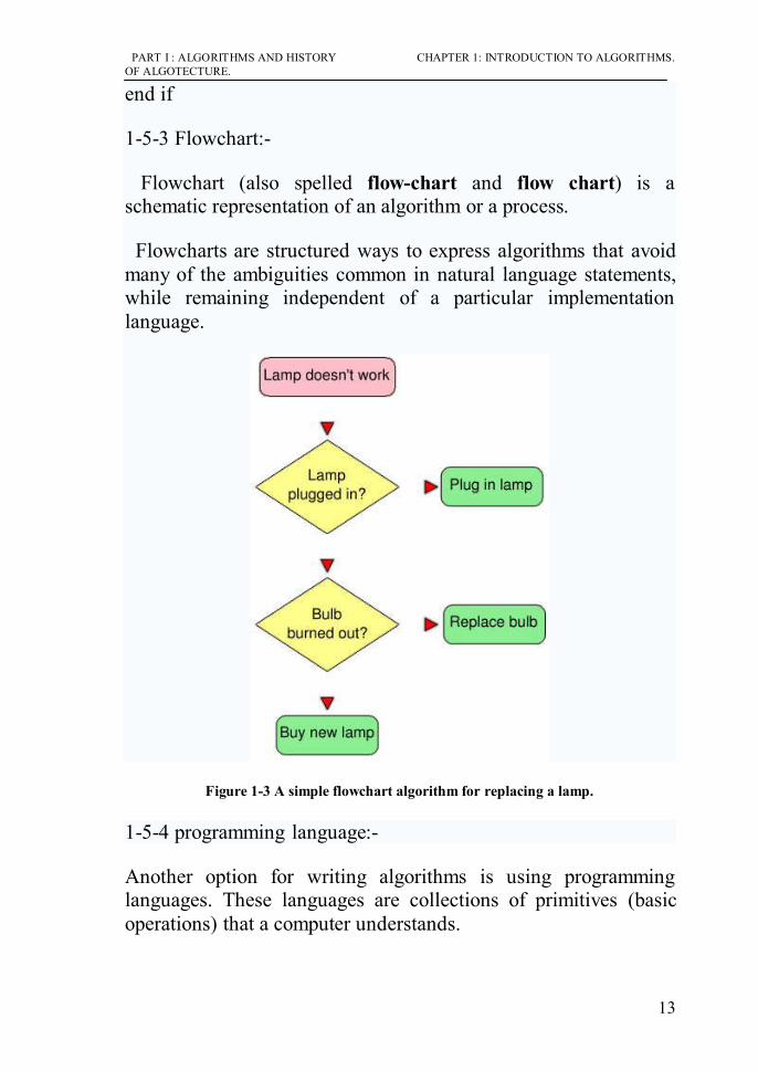
1-5-3 Flowchart:-
Flowchart (also spelled flow-chart and flow chart) is a schematic representation of an algorithm or a process.
Flowcharts are structured ways to express algorithms that avoid many of the ambiguities common in natural language statements, while remaining independent of a particular implementation language.
Figure 1-3 A simple flowchart algorithm for replacing a lamp.
1-5-4 programming language:-
Another option for writing algorithms is using programming languages. These languages are collections of primitives (basic operations) that a computer understands.

CHAPTER 1: INTRODUCTION TO ALGORITHMS. PART I : ALGORITHMS AND HISTORY OF ALGOTECTURE.
14
Programming language is an artificial language that can be used to control the behavior of a machine, particularly a computer. Programming languages, like human languages, are defined through the use of syntactic and semantic rules, to determine structure and meaning respectively. They are used to facilitate communication about the task of organizing and manipulating information, and to express algorithms precisely. Some authors restrict the term "programming language" to those languages that can express all possible algorithms, sometimes the term "computer language" is used for more limited artificial languages.
Programming languages are primarily intended for expressing algorithms in a form that can be executed by a computer, but are often used as a way to define or document algorithms.
1-6 Levels of Representing an Algorithm
There is a wide variety of representations possible and one can express a given Turing machine program as a sequence of machine tables as flowcharts (see more at state diagram), or as a form of rudimentary machine code or assembly code called "sets of quadruples" (see more at Turing machine).
Sometimes it is helpful in the description of an algorithm to supplement small "flow charts" (state diagrams) with natural-language and/or arithmetic expressions written inside "block diagrams" to summarize what the "flow charts" are accomplishing.
Representations of algorithms are generally classed into three accepted levels of Turing machine description1:
1-6-1 High-level description:
"...prose to describe an algorithm, ignoring the implementation details. At this level we do not need to mention how the machine manages its tape or head"1
1Sipser, Michael (2006). Introduction to the Theory of Computation. PWS Publishing Company. P.157.
PART I : ALGORITHMS AND HISTORY CHAPTER 1: INTRODUCTION TO ALGORITHMS. OF ALGOTECTURE.
15
1-6-2 Implementation description:
"...prose used to define the way the Turing machine uses its head and the way that it stores data on its tape. At this level we do not give details of states or transition function"2
1-6-3 Formal description
Most detailed, "lowest level", gives the Turing machine's "state table".
1-7 Implementation
Most algorithms are intended to be implemented as computer programs. However, algorithms are also implemented by other means, such as in a biological neural network (for example, the human brain implementing arithmetic or an insect looking for food), in an electrical circuit, or in a mechanical device.
Example,
One of the simplest algorithms is to find the largest number in an (unsorted) list of numbers. The solution necessarily requires looking at every number in the list, but only once at each. This problem can be solved by simple algorithm, which can be stated as follows :
English prose:
1. Assume the first item is the largest.
2. Look at each of the remaining items in the list and if it is larger than the largest item so far, make a note of it.
3. The last noted item is the largest in the list when the process is complete.
1 Ibid. 2 Ibid.

CHAPTER 1: INTRODUCTION TO ALGORITHMS. PART I : ALGORITHMS AND HISTORY OF ALGOTECTURE.
16
(Quasi-) Formal description: Written in prose but much closer to the high-level language of a computer program, the following is the more formal coding of the algorithm in pseudocode :
Algorithm LargestNumber Input: A non-empty list of numbers L. Output: The largest number in the list L. largest
← L0 for each item in the list L≥1, do if the item > largest, then largest
← the item return largest
"
←" is a loose shorthand for "changes to". For instance, "largest
← item" means that the value of largest changes to the value of item.
"return" terminates the algorithm and outputs the value that follows.
1-8 Classes
There are various ways to classify algorithms, each with its own merits.
1-8-1 Classification by implementation
One way to classify algorithms is by implementation means.
Recursion or iteration: A recursive algorithm is one that invokes (makes reference to) itself repeatedly until a certain condition matches, which is a method common to functional programming. Iterative algorithms use repetitive constructs like loops and sometimes additional data structures like stacks to solve the given problems. Some problems are naturally suited for one implementation or the other.

PART I : ALGORITHMS AND HISTORY CHAPTER 1: INTRODUCTION TO ALGORITHMS. OF ALGOTECTURE.
17
Logical: An algorithm may be viewed as controlled logical deduction. This notion may be expressed as:
Algorithm = logic + control.
The logic component expresses the axioms that may be used in the computation and the control component determines the way in which deduction is applied to the axioms. This is the basis for the logic programming paradigm. In pure logic programming languages the control component is fixed and algorithms are specified by supplying only the logic component. The appeal of this approach is the elegant semantics: a change in the axioms has a well defined change in the algorithm.
Serial or parallel or distributed: Algorithms are usually discussed with the assumption that computers execute one instruction of an algorithm at a time. Those computers are sometimes called serial computers. An algorithm designed for such an environment is called a serial algorithm, as opposed to parallel algorithms or distributed algorithms. Parallel algorithms take advantage of computer architectures where several processors can work on a problem at the same time, whereas distributed algorithms utilize multiple machines connected with a network. Parallel or distributed algorithms divide the problem into more symmetrical or asymmetrical sub problems and collect the results back together.
• Deterministic or non-deterministic: Deterministic algorithms solve the problem with exact decision at every step of the algorithm whereas non-deterministic algorithm solve problems via guessing although typical guesses are made more accurate through the use of heuristics.
Exact or approximate: While many algorithms reach an exact solution, approximation algorithms seek an approximation that is close to the true solution. Approximation may use either a deterministic or a random

CHAPTER 1: INTRODUCTION TO ALGORITHMS. PART I : ALGORITHMS AND HISTORY OF ALGOTECTURE.
18
strategy. Such algorithms have practical value for many hard problems.
1-8-2 Classification by design paradigm
Another way of classifying algorithms is by their design methodology or paradigm. There is a certain number of paradigms, each different from the other. Furthermore, each of these categories will include many different types of algorithms. Some commonly found paradigms include:
Divide and conquer: A divide and conquer algorithm repeatedly reduces an instance of a problem to one or more smaller instances of the same problem (usually recursively), until the instances are small enough to solve easily. One such example of divide and conquer is merge sorting. Sorting can be done on each segment of data after dividing data into segments and sorting of entire data can be obtained in conquer phase by merging them. A simpler variant of divide and conquer is called decrease and conquer algorithm. An example of decrease and conquer algorithm is binary search algorithm1.
Dynamic programming: When a problem shows optimal substructure, meaning the optimal solution to a problem can be constructed from optimal solutions to sub problems, and overlapping subproblems, meaning the same subproblems are used to solve many different problem instances, a quicker approach called dynamic programming avoids recomputing solutions that have already been computed. For example, the shortest path to a goal from a vertex in a weighted graph can be found by using the shortest path to the goal from all adjacent vertices.
1 A binary search algorithm (or binary chop) is a technique for finding a particular value in a sorted list. It makes progressively better guesses, and closes in on the sought value, by comparing an element halfway with what has been determined to be an element too low in the list and one too high in the list.

PART I : ALGORITHMS AND HISTORY CHAPTER 1: INTRODUCTION TO ALGORITHMS. OF ALGOTECTURE.
19
• The greedy method: A greedy algorithm is similar to a dynamic programming algorithm, but the difference is that solutions to the subproblems do not have to be known at each stage; instead a "greedy" choice can be made of what looks best for the moment.
• Reduction. This technique involves solving a difficult problem by transforming it into a better known problem for which we have (hopefully) asymptotically optimal algorithms. The goal is to find a reducing algorithm whose complexity is not dominated by the resulting reduced algorithm's.
• Search and enumeration. Many problems (such as playing chess) can be modeled as problems on graphs. A graph exploration algorithm specifies rules for moving around a graph and is useful for such problems. This category also includes search algorithms1, branch and bound2 enumeration and backtracking3.
The probabilistic and heuristic paradigm. Algorithms belonging to this class fit the definition of an algorithm more loosely.
Probabilistic algorithms are those that make some choices randomly (or pseudo-randomly); for some
1 A search algorithm, broadly speaking, is an algorithm that takes a problem as input and returns a solution to the problem, usually after evaluating a number of possible solutions. Most of the algorithms studied by computer scientists that solve problems are kinds of search algorithms. The set of all possible solutions to a problem is called the search space. 2 Branch and bound (BB) is a general algorithmic method for finding optimal solutions of various optimization problems, especially in discrete and combinatorial optimization.
3 Backtracking algorithms try each possibility until they find the right one. It is a depth-first search of the set of possible solutions. During the search, if an alternative doesn't work, the search backtracks to the choice point, the place which presented different alternatives, and tries the next alternative. When the alternatives are exhausted, the search returns to the previous choice point and tries the next alternative there. If there are no more choice points, the search fails.

CHAPTER 1: INTRODUCTION TO ALGORITHMS. PART I : ALGORITHMS AND HISTORY OF ALGOTECTURE.
20
problems, it can in fact be proven that the fastest solutions must involve some randomness.
Genetic algorithms attempt to find solutions to problems by mimicking biological evolutionary processes, with a cycle of random mutations yielding successive generations of "solutions". Thus, they emulate reproduction and "survival of the fittest". In genetic programming, this approach is extended to algorithms, by regarding the algorithm itself as a "solution" to a problem.
Heuristic algorithms, whose general purpose is not to find an optimal solution, but an approximate solution where the time or resources are limited. They are not practical to find perfect solutions.
1-8-3 Classification by field of study
Every field of science has its own problems and needs efficient algorithms. Related problems in one field are often studied together. Some example classes are search algorithms, sorting algorithms, merge algorithms, numerical algorithms, graph algorithms, string1 algorithms, computational geometric algorithms, combinatorial2 algorithms, machine learning, cryptography3, and data compression algorithms.
Fields tend to overlap with each other, and algorithm advances in one field may improve those of other, sometimes completely unrelated, fields. For example, dynamic programming was originally invented for optimization of resource consumption in
1 In computer programming and some branches of mathematics, a string is an ordered sequence of symbols. These symbols are chosen from a predetermined set or alphabet. 2 Combinatorics is a branch of pure mathematics concerning the study of discrete (and usually finite) objects. It is related to many other areas of mathematics, such as algebra, probability theory, ergodic theory and geometry, as well as to applied subjects in computer science and statistical physics. 3 Cryptography (or cryptology; from Greek κρυπτός, kryptos, "hidden, secret"; and γράφω, gráphō, "I write", or -λογία, -logia, respectively) is the practice and study of hiding information. In modern times, cryptography is considered a branch of both mathematics and computer science, and is affiliated closely with information theory, computer security, and engineering.

PART I : ALGORITHMS AND HISTORY CHAPTER 1: INTRODUCTION TO ALGORITHMS. OF ALGOTECTURE.
21
industry, but is now used in solving a broad range of problems in many fields.
1-8-4 Classification by complexity
Algorithms can be classified by the amount of time they need to complete compared to their input size. There is a wide variety: some algorithms complete in linear time relative to input size, some do so in an exponential amount of time or even worse, and some never halt. Additionally, some problems may have multiple algorithms of differing complexity, while other problems might have no algorithms or no known efficient algorithms. There are also mappings from some problems to other problems. Owing to this, it was found to be more suitable to classify the problems themselves instead of the algorithms into equivalence classes based on the complexity of the best possible algorithms for them.
1-9 General characteristics of algorithms.
Characteristics of algorithms can be identified as follows:-
1-9-1 Algorithms are well-ordered.
Since an algorithm is a collection of operations or instructions, we must know the correct order in which to execute the instructions. If the order is unclear, we may perform the wrong instruction or we may be uncertain which instruction should be performed next. This characteristic is especially important for computers. A computer can only execute an algorithm if it knows the exact order of steps to perform.
1-9-2 Algorithms have unambiguous operations.
Each operation in an algorithm must be sufficiently clear so that it does not need to be simplified. Given a list of numbers, you can easily order them from largest to smallest with the simple instruction "Sort these numbers." A computer, however, needs more detail to sort numbers. It must be told to search for the smallest number, how to find the smallest number, how to

CHAPTER 1: INTRODUCTION TO ALGORITHMS. PART I : ALGORITHMS AND HISTORY OF ALGOTECTURE.
22
compare numbers together, etc. The operation "Sort these numbers" is ambiguous to a computer because the computer has no basic operations for sorting. Basic operations used for writing algorithms are known as primitive operations or primitives. When an algorithm is written in computer primitives, then the algorithm is unambiguous and the computer can execute it.
1-9-3 Algorithms have effectively computable operations.
Each operation in an algorithm must be doable, that is, the operation must be something that is possible to do. Suppose you were given an algorithm for planting a garden where the first step instructed you to remove all large stones from the soil. This instruction may not be doable if there is a four ton rock buried just below ground level. For computers, many mathematical operations such as division by zero or finding the square root of a negative number are also impossible. These operations are not effectively computable so they cannot be used in writing algorithms.
1-9-4 Algorithms produce a result.
In our simple definition of an algorithm, we stated that an algorithm is a set of instructions for solving a problem. Unless an algorithm produces some result, we can never be certain whether our solution is correct. Have you ever given a command to a computer and discovered that nothing changed? What was your response? You probably thought that the computer was malfunctioning because your command did not produce any type of result. Without some visible change, you have no way of determining the effect of your command. The same is true with algorithms. Only algorithms which produce results can be verified as either right or wrong.
1-9-5 Algorithms halt in a finite amount of time.
Algorithms should be composed of a finite number of operations and they should complete their execution in a finite amount of

PART I : ALGORITHMS AND HISTORY CHAPTER 1: INTRODUCTION TO ALGORITHMS. OF ALGOTECTURE.
23
time. Suppose we wanted to write an algorithm to print all the integers greater than 1. Our steps might look something like this:
1. Print the number 2. 2. Print the number 3. 3. Print the number 4.
While our algorithm seems to be pretty clear, we have two problems. First, the algorithm must have an infinite number of steps because there are an infinite number of integers greater than one. Second, the algorithm will run forever trying to count to infinity. These problems violate our definition that an algorithm must halt in a finite amount of time. Every algorithm must reach some operation that tells it to stop.

CHAPTER 1: INTRODUCTION TO ALGORITHMS. PART I : ALGORITHMS AND HISTORY OF ALGOTECTURE.
24

PART I : ALGORITHMS AND HISTORY CHAPTER 2: A BRIEF HISTORY OF ALGOTECTURE. OF ALGOTECTURE.
25
-Conclusion - An algorithm is a well-ordered collection of unambiguous and effectively computable operations that when executed produces a result and halts in a finite amount of time. - An algorithm can be seen as a mediator between the
human mind and the computer’s processing power. This ability of an algorithm to serve as a translator can be interpreted as bi-directional: either as a dictation to the computer how to go about solving the problem, or as a reflection of a human thought into the form of an algorithm
- Algorithms can be expressed in many kinds of notations,
including natural languages , pseudocode, flowcharts, and programming languages
- Levels of Representing an Algorithm are high level
description, implementation description, formal description. - Algorithms can be classified by the following :
by Implementation: Iteration, logical, serial, ..etc. by design paradigms: Divide, dynamic programming,..etc. by field of study: numerical, string,…etc. by complexity.
- General characteristics of algorithms:
Algorithms are well ordered, Algorithms have unambiguous operations, Algorithms should produce results, Algorithms halt in a finite amount of time.

CHAPTER 2: A BRIEF HISTORY OF ALGOTECTURE. PART I : ALGORITHMS AND HISTORY OF ALGOTECTURE.
26

PART I : ALGORITHMS AND HISTORY CHAPTER 2: A BRIEF HISTORY OF ALGOTECTURE. OF ALGOTECTURE.
27
CHAPTER 2: A BRIEF HISTORY OF ALGOTECTURE

CHAPTER 2: A BRIEF HISTORY OF ALGOTECTURE. PART I : ALGORITHMS AND HISTORY OF ALGOTECTURE.
28

PART I : ALGORITHMS AND HISTORY CHAPTER 2: A BRIEF HISTORY OF ALGOTECTURE. OF ALGOTECTURE.
29
CHAPTER 2:
A BRIEF HISTORY OF ALGOTECTURE
“Algotecture is a term coined here to denote the use of algorithms in architecture. This term differs from the popular terms CAD or computer graphics in the sense that algorithms are not necessarily dependent on computers whereas the former are, at least, by definition. This distinction is very important as it liberates, excludes, and disassociates the mathematical and logical processes used for addressing a problem from the machine that facilitates the implementation of those processes. Such a use involves the articulation of a strategy for solving problems whose target is known, as well as to address problems whose target cannot be defined.”1 Within the realm of computer graphics, solutions can be built for almost any problem whose complexity, amount, or type of work justifies the use of a computer. For instance, in architectural practice, inputting data points, calculating structural elements, or printing large line drawings are tasks, or problems, that require the use of the computer even though they can be performed manually. Yet, there are some problems whose complexity, level of uncertainty, ambiguity, or range of possible solutions required a synergetic relationship between the human mind and a computer system. Such a synergy is possible only through the use of algorithmic strategies that ensure a complementary and dialectic relationship between the human mind and the machine.
1 Terzidis, Kostas (2006). Algorithmic Archtecture. Architectural Press, Elsevier. P. 37, op.cit.

CHAPTER 2: A BRIEF HISTORY OF ALGOTECTURE. PART I : ALGORITHMS AND HISTORY OF ALGOTECTURE.
30
This chapter will discuss the history of applying algorithms in architecture ( in other words, history of using computers-through programming- in creating architectural designs and not in drafting)
Figure 2.1. Applications of computers in architecture.
The history of applying computers in architecture can be explained in the next three successive steps ( by appearance) and some of these applications can be classified as an algotecture while others are not, these steps are as follows1 (Fig 2.1):-
a. Automated design systems, represent the first step in applying algorithms in architecture.
b. Augmented design systems, represent the second step for applying computers in architecture and it is not an algotecture. This step is only using computers in drafting or presentation. ( out of scope)
c. Formalistic design, represents the second step in applying algorithms in architecture.
In the next part, the Automated design systems and formalistic design are going to be discussed as a brief history for applying algorithms in architecture.
1 Ibid, p. 40.

PART I : ALGORITHMS AND HISTORY CHAPTER 2: A BRIEF HISTORY OF ALGOTECTURE. OF ALGOTECTURE.
31
2-1 Automated design Systems.
In the early 1960s, Alexander 1published a highly influential book titled “Notes on the Synthesis of Form”. In this book Alexander quotes the need for rationality in the design process. If design, he argues, is a conceptual interaction between form and context, there may be a way to improve it by making an abstract picture of the problem, which will retain only its abstract structural features. As a mathematician, he introduced set theory, structural analysis, and the theory of algorithms as tools for addressing the design problem. He asserted that even quality issues can be represented by binary variables. If a misfit occurs, the variable takes the value 1; if not, 0.
The previous paragraph reflects the ideology at that time and represents the initiation of using algorithms through computers in architectural design. In the next part, the types of Automated design systems will be stated.
2-1-1 Linguistic approach.
An approach to solve design problems is that of linguistics (at 1957) Here, the designer attempts to structure the problem by grouping the constraints into thematic areas (e.g. zoning, circulation), and then the designer determines each group of constraints more or less independently. This information is converted into linguistic structures through the use of transformational rules. Then, the designer represents these linguistic structures in the form of sentences2, these sentences represent specific sets of design elements, which include not only the elements but also the rules which allow a designer to combine them into feasible and meaningful compositions. The aim of this approach became one of writing algorithms for the generation of feasible and meaningful design "sentences." 1 Alexander, C., Notes on the Synthesis of Form. Cambridge:Harvard University Press, 1967. 2 Chomsky , N., Syntactic Structures, The Hague: Mouton & Company, 1957.

CHAPTER 2: A BRIEF HISTORY OF ALGOTECTURE. PART I : ALGORITHMS AND HISTORY OF ALGOTECTURE.
32
2-1-2 Graph Theory In 1964 'Levin'1 used an analytical tool box available for the study of complex systems that is rooted in a powerful subfield of mathematics, called "graph theory", which originated in the eighteenth century work of 'Euler'2. The system of elements that interact or regulate each other (a network) can be represented by a mathematical object called a graph. A graph is a collection of nodes and edges: the interacting components of the system are reduced to a set of nodes, and the interactions among the components are represented by edges. A Graph can represent any kind of relationship, and architecture is a certain kind of relationship, thus, could be explained suitably by graph. Since then, graph theory has been implemented using algorithms to analyze potentials of individual spaces that compose together a wider system of space3. The next figure and table describe basic concept of graph and its geometry. (Fig. 2.2, Table 2.1).
Fig. 2.2 Linear graph diagram.
1 Levin, P. H.: Use of Graphs to Decide the Optimum Layout of Buildings. Architect, 14, p.p 809–815, 1964.
2 Leonhard Paul Euler (15 April 1707 – 18 September [O.S. 7 September] 1783) was a pioneering Swiss mathematician and physicist who spent most of his life in Russia and Germany.Euler made important discoveries in fields as diverse as calculus and graph theory. He also introduced much of the modern mathematical terminology and notation, particularly for mathematical analysis, such as the notion of a mathematical function.
3 Kalay, E.Y.: Modeling Objects and Environment, John Wiley & sons, 1987.

PART I : ALGORITHMS AND HISTORY CHAPTER 2: A BRIEF HISTORY OF ALGOTECTURE. OF ALGOTECTURE.
33
Tab. 2.1: Geometric measures of node in minimum-path graph1.
Researchers suggested that the application of this formalism would permit established graph theory algorithms to be implemented within layout generation systems. Figure 2.3 illustrates this representation scheme. In this illustration, a set of adjacency requirements is initially provided by the user (Fig. 2.3a). Based on these requirements, a graph is constructed where the spaces are represented as nodes and the adjacency requirements are represented as links between the nodes (Fig. 2.3b).
1 Nophaket N.: The Graph Geometry for Architectural Planning. Journal of Asian Architecture and Building Engineering, May 2004.

CHAPTER 2: A BRIEF HISTORY OF ALGOTECTURE. PART I : ALGORITHMS AND HISTORY OF ALGOTECTURE.
34
Fig. 2.3: Generating a relationship graph from a relationship matrix.
The graph contains no intersecting links, given this condition. Graph theories prove that all relationships can be accommodated in a 2-dimensional plane. Given the planar requirements graph, a series of potential layouts may be generated which satisfy the spatial requirements (Fig. 2.4a). Finally, a second graph representation, referred to as a dual graph, characterizes the layout adjacencies and common walls by distinguishing the north-south adjacency links from the east-west adjacency links (Fig. 2.4b)1.
1 Chinowsky, P. S.: The CADDIE Project: Applying Knowledge-Based Paradigms to Architectural Layout Generation. Ph.D. thesis, department of civil engineering, Stanford University, May 1991.

PART I : ALGORITHMS AND HISTORY CHAPTER 2: A BRIEF HISTORY OF ALGOTECTURE. OF ALGOTECTURE.
35
Fig. 2.4: Layout alternatives and a dual graph representation.
2-1-3 Machine Learning.
Some theorists have argued that many problems cannot be solved algorithmically, either because the procedure leading to their solution is ill-defined or because not all the information needed to solve them is available or accurate1. Such problems make it necessary to use heuristic2 and adaptive decision procedures. Heuristic methods typically rely on trial-and-error techniques to arrive at a solution. Such techniques are, by definition, much closer to the search-and-evaluate processes used in architectural design. In adaptive procedures, the computer itself learns by experience, as in Negroponte's "architecture machine" at 1970, which could follow a procedure and, at the same time, could "discern and assimilate" conversational idiosyncrasies. This machine, after observing a user's behavior, could reinforce the dialogue by using a predictive model to respond in a manner consistent with personal behavior and idiosyncrasies. The dialogue would be so intimate, "that only mutual persuasion and compromise would bring about ideas."3 The role of the machine
1 Terzidis, K., Algorithmic Architecture, Architectural Press, 2006, p.19. 2 Heuristic (hyu-ˈris-tik) is an adjective for methods that help in problem solving in turn leading to learning and discovery. These methods in most cases employ experimentation and trial and error techniques. A heuristic method is particularly used to rapidly come to a solution that is reasonably close to the best possible answer, or 'optimal solution'. 3Negroponte, N., The Architecture Machine. Cambridge: MIT Press, 1970. p.13

CHAPTER 2: A BRIEF HISTORY OF ALGOTECTURE. PART I : ALGORITHMS AND HISTORY OF ALGOTECTURE.
36
would be that of a close and wise friend assisting in the design process.
2-1-4 Automated design.
In the 1970s with the introduction of the first relatively complex computers, theorists investigated into the possibility of self-designing machines. They thought that one of the areas where the computer could be helpful to a designer could be in automatic design, that is, in finding a large number of possible schemes at a sufficiently early stage of the design process, and choosing the best one for further development. An early attempt was MIT's BUILD system1 which could be used to describe spaces that might go into a building, indicating their dimensions, their arrangement, and their materials. The computer then arranged the spaces solving the problem. This approach has been used extensively for solving complex design problems that are related to arranging parameters in optimum locations2. These approaches focus on the functionality of the end design product and do not take into account aesthetic or artistic parameters. In fields such as design of computer chips, nuclear plants, or hospitals automatic spatial allocation plays a very important role today.(Fig.2.5)
1 Dietz, A. , Dwelling House Construction Cambridge: MIT Press, 1974.p.18 2 Eastman C. M. and Henrion M., M. GLIDE: Language for a Design Information System. Pittsburg: Carnegie-Mellon University, Institute of Physical Planning, 1967.

PART I : ALGORITHMS AND HISTORY CHAPTER 2: A BRIEF HISTORY OF ALGOTECTURE. OF ALGOTECTURE.
37
Figure 2.5 Space allocation process: (a) grid (b) site (c) program (d) relationship table (f) solution
2-1-5 Expert Systems
"Expert systems" are subset of Artificial Intelligence1 (AI) tools. In these systems, design knowledge is represented within the condition-action formalism of rules. The rules capture the specific conditions under which designers reach decisions for a limited design domain, together with the actions a designer takes when these conditions are present. For example, the following rules capture a design focusing on the placement of two spaces with a required adjacency2:
1 Artificial intelligence (AI) is a branch of computer science concerned with the problem of how to simulate human intelligence. AI is as old as the invention of the first computer, or, to be more precise, of the first counting machine. 2 Chinowsky, P. S.: The CADDIE Project: Applying Knowledge-Based Paradigms to Architectural Layout Generation. Ph.D. thesis, department of civil engineering, Stanford University, May 1991. op.cit.

CHAPTER 2: A BRIEF HISTORY OF ALGOTECTURE. PART I : ALGORITHMS AND HISTORY OF ALGOTECTURE.
38
This use of previous design information includes the adaptation of design concepts, design methodologies, forms, and goals. As designers gain more experience in a given area, successful solutions to previous design problems become prototypes for future problems. Once these prototypes are developed, a designer rarely develops new prototypes due to the extensive knowledge which exists in previous prototypes (Fig. 2.6)1.
Fig. 2.6: Prototypes refinement rules select appropriate prototypes based on layout
conditions.
2-2 Formalistic design.
Formalistic design is viewed as an activity, which entails invention and exploration of new forms and their relations. Various methods of analysis have been employed in the search of new forms: formal analysis involves the investigation of the properties of a formal subject. Composition, geometrical attributes, and morphological properties obeying Galilean and Newtonian principles are extracted from figural appearances of an 1 Ibid.

PART I : ALGORITHMS AND HISTORY CHAPTER 2: A BRIEF HISTORY OF ALGOTECTURE. OF ALGOTECTURE.
39
object. In contrast, structural analysis deals with the derivation of the motivations and propensities which are implicit within form and which may be used to define the limit between what it is and all other possibilities. 2-2-1 Shape Grammars The Shape Grammars1 approach was developed as an architectural theory to analyze and synthesize architectural schemes. Although initially developed to carry out spatial computations visually, it was later on extended to explain design phenomena, such as stylistic changes2, and to simulate behavioral patterns of design, such as languages of design3. A Shape Grammar consists, in general terms, of an initial shape, and a set of production rules. The rules apply to the initial shape and to shapes produced by previous rules applications, to generate designs. All designs generated by the rules comply with the language generated by a grammar. A shape grammar has four components: 1. S is a finite set of shapes; 2. L is a finite set of symbols; 3. R is a finite set of rules of the form a “ b, where a is a labeled shape in (S, L)+”, and “b is a labeled shape in (S, L)*”; and, 4.I is a labeled shape in (S, L)+ called the initial shape. Thus, after establishing a vocabulary in the form of a finite set of shapes and symbols, the shape grammar formalism makes possible to define a set of production rules with them (see figure below). A rule in this sense is not a restriction but rather a
1 Stiny, G., "Computing with Form and Meaning in Architecture", Journal of Architectural Education 39, 1985, pp. 7-19. 2 Knight, T. W., Transformations of Languages of Design, Ph.D.Dissertation. Los Angeles: University of California, 1986. 3 Flemming, U., "The Role of Shape Grammars in the Analysis and Creation of Design", Proceedings of Symposium on Computability of Design at SUNY Buffalo, (December 1986).

CHAPTER 2: A BRIEF HISTORY OF ALGOTECTURE. PART I : ALGORITHMS AND HISTORY OF ALGOTECTURE.
40
representation of actions to be performed when specific conditions are met. The right side of the rule represents the conditions to be met for the rule to be applied, and the left side represents the action to be taken if the conditions are present. The grammar thus defined allows transforming a shape or configuration into another shape or configuration by applying one rule at a time. This is done by replacing “marked” instances of the shape on the lefthand side of the rule, with the shape or shapes in the right hand side. A special symbol such as a dot (.) is used to identify and distinguish “marked” instances of a shape, and an implementation arrow to separate the right from the left-hand sides of the rule. All shapes on the left-hand side of the rule definition must be marked while the shapes in the right hand side may or may not be marked. If the shape or shapes on the right side are not marked, the instance of the application of that particular rule cannot be further transformed, since only marked shapes can be affected by rules. Figure 2.7 shows a simple six-rule grammar derived from a vocabulary of two primitive shapes, and two basic symbols.
Fig. 2.7: Sample shape grammar.
The dot on the left side of rules 1 and 4 indicates an empty shape. Rules like these are used to start the production process by adding

PART I : ALGORITHMS AND HISTORY CHAPTER 2: A BRIEF HISTORY OF ALGOTECTURE. OF ALGOTECTURE.
41
the initial shape to a layout (shape being created by the grammar). Rules 2 and 5 are typical production rules that add a new shape to the layout. In this grammar, both rules “unmark” the shape to which they were applied (base shape of the rule), and add a “marked” new shape so that further rules can be applied to it. Rules 3 and 6 “unmark” shapes A and B respectively. In this particular grammar, any application of rule 3 to shape A or rule 6 to shape B, will terminate the production process since in both cases the only marked shape left will be unmarked, eliminating the possibility of further rule applications (see figure below , where the number of rule applications is limited to 5 rules only).
Fig. 2.8: Sample layout using the Shape grammar.
Shape Grammars provide a theoretical framework for understanding designs, for constructing languages of designs and for explaining phenomena of design such as stylistic changes1. Furthermore, as a theory of architecture, Shape Grammars provide mechanisms for understanding shapes as designs, by first appealing to compositional styles characterized by languages 1 Knight, T. W., Transformations of Languages of Design, Ph.D. Dissertation. Los Angeles: University of California, 1986.

CHAPTER 2: A BRIEF HISTORY OF ALGOTECTURE. PART I : ALGORITHMS AND HISTORY OF ALGOTECTURE.
42
defined by grammars, and then to languages of descriptions to provide accounts to designs in terms of their function, meaning, etc.
Fig. 2.9: Various 3d forms generated with Shape grammars.
2-2-2 Generative Systems. An interesting variation of shape grammars is that of fractal1 generative systems. Based on a scheme, formulated by the German mathematician Von Koch, a fractal process consists of an initial shape (the base) and one or more generators. From a practical point of view, the generator is a production rule: each and every line segment of the base is replaced by the shape of the
1 Fractal is an object or quantity that displays self-similarity on all scales with non-integer dimensions. The object need not exhibit exactly the same structure at al l scales, but the same “type” of structures must appear on all scales.

PART I : ALGORITHMS AND HISTORY CHAPTER 2: A BRIEF HISTORY OF ALGOTECTURE. OF ALGOTECTURE.
43
generator1. The implementation of an interactive computer program has been reported by Yessios that allows the fractal to be generated one at a time or at multiple increments, backwards or forwards. As described by Yessios, “a building typically has to respond to a multiplicity of processes, superimposed or interwoven. Therefore, the fractal process has to be guided, to be constrained and to be filtered. The fractal process has to be ‘mutated’ by the utilitarian requirements of the functionality of a building. 2
Figure 2.10 A generative theme.
The example below shows how a 2D vector-base fractal can be transformed into 3D vector-base fractal. Yessios’s3 implemented a fractal generation that was highly interactive and allowed a fractal to be developed one iteration at a time or at multiple increments. At the same time, generators could be changed, replaced, deleted, or inserted, at any iteration. The generation process could go forward and backward allowing the designer to return to an earlier state. In (Fig. 2.11a) the base and the generator are one and the same shape. The fractal generated after 30 steps (Fig. 2.11b). It has been 1 Yessios C. "A Fractal Studio", ACADIA 87 Proceedings, North Carolina State University, 1987. 2 Ibid p.7. 3 Yessios, C.I.: A Fractal Studio. In ACADIA ’87 Workshop Proceedings.1987, op.cit.

CHAPTER 2: A BRIEF HISTORY OF ALGOTECTURE. PART I : ALGORITHMS AND HISTORY OF ALGOTECTURE.
44
filtered and transformed into a structured drawing (floor plan) which next becomes the base for generating a 3D building model. An interior model is shown in (Fig. 2.11c) and two views of the exterior model are shown in (Fig. 2.11d) and (Fig. 2.11e).
Fig. 2.11: Assigning height to a 2d vector-base fractals.
2-2-4 Transformation (Morphing) Transformation or morphing is a process in which an object changes its form gradually in order to obtain another form. The operation of transformation consists basically of the selection of two objects and the assignment of n, the number of in-between steps. The first object then transforms into the second in n steps. This process is illustrated in the figure below. The transformation preserves the structural integrity of the objects involved, that is, an object changes into another object as a single entity. There are many possible ways an object can be transformed. By matching pairs of points, edges, or faces, one of each object, the transformation process can be altered. Orchestration is a term used to describe the actions of selecting, assigning, directing and evaluating the performance of objects, which participate in a transformation. Transformations can happen concurrently and/or in different speeds. The result is a moving

PART I : ALGORITHMS AND HISTORY CHAPTER 2: A BRIEF HISTORY OF ALGOTECTURE. OF ALGOTECTURE.
45
image the behavior of which becomes the responsibility of the user. As in an orchestra performance the designer/composer selects a number of objects he wants to include, assigns the proper transformation paths and speeds, and then directs the performance through time, form and color. The essence of such transformational design is not that much in the final form but rather in the intermediate phases these transformations pass through, as well as, in the extrapolations which go beyond the final form. The user has the capability, through the system, to modify and control the flow of the compositional evolution and replay it many times by varying some or all of the transformational parameters.
Fig. 2.12: The transformation process.
One interesting exploration of shape transitions has been reported by Yessios (1987). According to him an initial shape A can be transformed to a target shape B by applying any number of in-between steps. All the points of shape A are mapped onto shape B and vice-versa. Furthermore, once the rules of transition have been established, the transition can be allowed to continue beyond its target, to infinity1.
1 Yessios C. "A Fractal Studio", ACADIA 87 Proceedings, North Carolina State University, 1987.
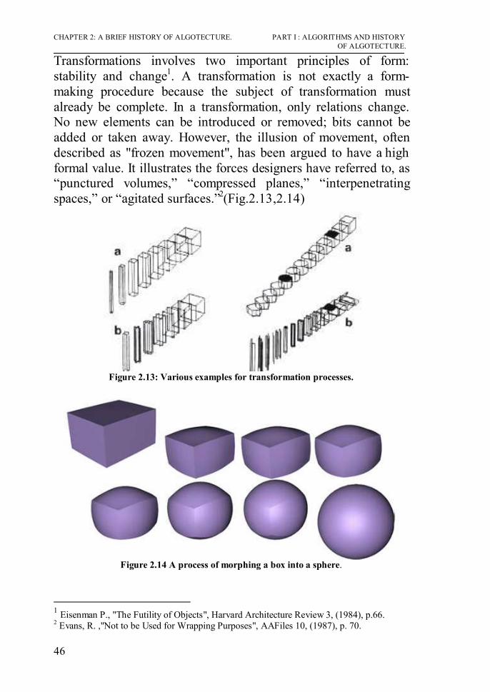
CHAPTER 2: A BRIEF HISTORY OF ALGOTECTURE. PART I : ALGORITHMS AND HISTORY OF ALGOTECTURE.
46
Transformations involves two important principles of form: stability and change1. A transformation is not exactly a form-making procedure because the subject of transformation must already be complete. In a transformation, only relations change. No new elements can be introduced or removed; bits cannot be added or taken away. However, the illusion of movement, often described as "frozen movement", has been argued to have a high formal value. It illustrates the forces designers have referred to, as “punctured volumes,” “compressed planes,” “interpenetrating spaces,” or “agitated surfaces.”2(Fig.2.13,2.14)
Figure 2.13: Various examples for transformation processes.
Figure 2.14 A process of morphing a box into a sphere.
1 Eisenman P., "The Futility of Objects", Harvard Architecture Review 3, (1984), p.66. 2 Evans, R. ,"Not to be Used for Wrapping Purposes", AAFiles 10, (1987), p. 70.

PART I : ALGORITHMS AND HISTORY CHAPTER 2: A BRIEF HISTORY OF ALGOTECTURE. OF ALGOTECTURE.
47
2-2-5 Parametric Variations Parametric design is turning design into a set of principles encoded as a sequence of parametric equations. These equations are used to express certain quantities as explicit functions of a number of variables1. By changing any parameter in the equation new forms and new shapes could be generated. The parameters are not just numbers relating to Cartesian geometry, they could be performance based criteria such as light levels or structural load resistance, or even a set of aesthetic principles. Parametric design refers to Cartesian geometry and the ability to modify the geometry by means other than recomposition. Thus the term "parametric design" is more accurately referred to as "associative geometry". Each time a value for any parameter changes, the model simply regenerates to reflect the new geometry. A parametric description of form provides high potentiality to generate complex curves and ruled surfaces. Ruled surfaces2 are able to accomplish high levels of form complexity, especially by their intersections when assembled. Ruled surfaces have been extensively applied in architecture to generate unordinary forms.
It is possible to create a simple parametric system to generate an almost complete set of building types based on ruled surfaces.\ Parametric design systems can generate a wide variety of buildings in a very simple way.
1Kolarevic, B.: Digital Morphogenesis. In B. Kolarevic, (Ed) Architecture in the Digital Age, Design and Manufacturing. New York: Spon Press, 2003. 2 Ruled surface is a surface swept out by a straight line L moving along a curve b.Such a surface thus always has a parameterization in ruled form x(u,v)=b(u)+v d(u), where b is the base curve and d is the director curve.

CHAPTER 2: A BRIEF HISTORY OF ALGOTECTURE. PART I : ALGORITHMS AND HISTORY OF ALGOTECTURE.
48
Restaurant Los Manantiales in Mexico was generated using parametric equations, the values of the parameters are presented in 12x n matrices. where n is the number of surfaces. Active parameters of each surface take a real or integer number value, otherwise they are set to 0. Each surface of the building can be expressed using six parameters, three for the base curve and three for the director curve. Next, all surfaces had to be assembled in the common framework of the composition. This required a set of transformations (translation and rotation around each axis) to be applied to every surface in order to orient and locate it in the general framework and create the network of interrelated surfaces. When all n surfaces are indexed, a 12x n matrix can represent a building1.
Where:
tx : translation of surface around X axis ty : translation of surface around Y axis
1 Ibid. p.35.

PART I : ALGORITHMS AND HISTORY CHAPTER 2: A BRIEF HISTORY OF ALGOTECTURE. OF ALGOTECTURE.
49
tz : translation of surface around Z axis rx : rotation of surface around Z axis ry : rotation of surface around Z axis rz : rotation of surface around Z axis n: total number of surfaces that compose the represented building.
Fig. 2.15: Los Manantiales represented parametrically in a defined matrix.

CHAPTER 2: A BRIEF HISTORY OF ALGOTECTURE. PART I : ALGORITHMS AND HISTORY OF ALGOTECTURE.
50

PART I : ALGORITHMS AND HISTORY CHAPTER 2: A BRIEF HISTORY OF ALGOTECTURE. OF ALGOTECTURE.
51
-Conclusion - Algotecture is a term used here to denote the use of algorithms in architecture. - Algotecture is applied in architecture through the use of computers in the form of designing and thinking in the architectural design. - The history of using algorithms in architectural design can be summarized in the following figure.
History of Algotecture
Automated design systems Formalistic design
Using algorithms in architecture to automatically generate designs (Mainly plans and relationships between elements)
Using algorithms in architecture to generate only forms based on certain rule done by the architect.
1- Linguistic approach.
2- Graph Theory.
3- Machine learning.
4- Automated design (Build system).
5- Expert systems.
1- Shape Grammars.
2- Generative systems.
3- Transformation.
4- Parametric Variations.

PART II : IMPLEMENTED ALGORITHMS IN CHAPTER 3: MAIN ALGORITHMS APPLIED IN CONTEMPORARY ARCHITECTURE. CONTEMPORARY ARCHITECTURE.
53
PART II
IMPLEMENTED ALGORITHMS IN CONTEMPORARY ARCHITECTURE

CHAPTER 3: MAIN ALGORITHMS APPLIED IN PART II : IMPLEMENTED ALGORITHMS IN CONTEMPORARY ARCHITECTURE. CONTEMPORARY ARCHITECTURE.
54

PART II : IMPLEMENTED ALGORITHMS IN CHAPTER 3: MAIN ALGORITHMS APPLIED IN CONTEMPORARY ARCHITECTURE. CONTEMPORARY ARCHITECTURE.
55
CHAPTER 3:
MAIN ALGORITHMS APPLIED IN CONTEMPORARY ARCHITECTURE

CHAPTER 3: MAIN ALGORITHMS APPLIED IN PART II : IMPLEMENTED ALGORITHMS IN CONTEMPORARY ARCHITECTURE. CONTEMPORARY ARCHITECTURE.
56

PART II : IMPLEMENTED ALGORITHMS IN CHAPTER 3: MAIN ALGORITHMS APPLIED IN CONTEMPORARY ARCHITECTURE. CONTEMPORARY ARCHITECTURE.
57
CHAPTER 3:
MAIN ALGORITHMS APPLIED IN
CONTEMPORARY ARCHITECTURE Introduction. This next section is to explain how architectural algorithms are created by computers to help in architectural design. Generally, creating a design using digital processes can be done by two methods, either using previously designed software for modeling forms which make the architect only draws his form, or writing an algorithm using programming languages which helps the designer in thinking by creating designs (a small design program that executes design). The use of algorithms creates new forms for buildings, which respects the rules previously verified by the architect. Architects begin to create algorithms that can help them in their designs. Algorithmic design can produce significantly different and more unexpected designs than conventional CAD software, since the algorithms make the computers think and take decisions with the architect. Despite the power of industrial strength 3D modelers such as CATIA and Maya, but these modelers still only a drawing tool and not a design tool to think with the designer. Algorithmic form generation is familiar in the engineering design disciplines: civil and aeronautical engineering and naval architecture, where three-dimensional shapes are more strictly dictated by functional requirements expressed as mathematical equations.

CHAPTER 3: MAIN ALGORITHMS APPLIED IN PART II : IMPLEMENTED ALGORITHMS IN CONTEMPORARY ARCHITECTURE. CONTEMPORARY ARCHITECTURE.
58
If a designer wants to run an algorithm to help him in design, he must decide between two main alternatives1 :
Macro facilities and scripting languages within CAD modelers are relatively easy to learn, but they inherently limit the programs one can write (and hence the forms one can generate).
Programs created by programming languages such as C and Java are powerful but they require more effort to learn, and generating 3D geometry also requires attention to many language features that have no direct bearing on form.
3-1 Methods of running an algorithm for designing architecture:
The following table 3.1 distinguishes five levels of support for algorithmic design provided by CAD modelers.
Tab. 3.1 Support for algorithmic form generation.2
1 Gross, Mark D., FormWriter A Little Programming Language for Generating Three-Dimensional Form Algorithmically, CAAD futures 2001.p.578 2 Ibid p.578.

PART II : IMPLEMENTED ALGORITHMS IN CHAPTER 3: MAIN ALGORITHMS APPLIED IN CONTEMPORARY ARCHITECTURE. CONTEMPORARY ARCHITECTURE.
59
3-1-1 The simplest modelers provide no support at all for algorithmic generation: models can be constructed directly using the geometric primitives and operations provided on the CAD modeler's menus. Most CAD modeling programs offer macro facilities or scripting language. Although a macro facility serves simple tasks well (such as repetitive window patterns or stairs), it is difficult to program more complex operations using only macros. Scripting languages, which have gained wide acceptance in other domains (witness JavaScript and Flash), provide considerably more power than macros but coding more sophisticated tasks becomes quite complex, requiring a specialist programmer.
3-1-2 An embedded programming language, like a scripting
language, enables the programmer to control and command the modeler from an environment within the CAD program, and allows more powerful constructs than the typical scripting language. Many CAD programs now include an embedded language, and advanced users of these CAD programs use it. AutoLisp 1 is the best known example. Although the underlying Lisp language is extremely elegant and powerful, Autodesk’s implementation was a weak one and the programming environment for developing AutoLisp routines is weak by the modern standards.
3-1-3 Programming languages such as C or Java can be used to
run algorithms for architecture design but it requires more expertise than most designers need to commit to acquiring, but with these languages produce the best results.
3-2 Most popular algorithms applied in architectural design. In the previous decade many algorithms (infinite) are implemented in architectural design with their wide applications, some of these algorithms are more common than others, others are created for solving certain problems in certain designs, and others are used for generating certain forms.

CHAPTER 3: MAIN ALGORITHMS APPLIED IN PART II : IMPLEMENTED ALGORITHMS IN CONTEMPORARY ARCHITECTURE. CONTEMPORARY ARCHITECTURE.
60
The following part of this chapter is going to discuss the most popular algorithms used in contemporary architecture such as Voronoi, A*, L-Systems, Swarm,…etc, In addition to other examples for special algorithms to generate forms. 3-2-1 Voronoi Algorithms. 3-2-1-1 Definition Voronoi diagram1 is the partitioning of a plane with points into convex polygons such that each polygon contains exactly one generating point and every point in a given polygon is closer to its generating point than to any other. A Voronoi diagram is sometimes also known as a Dirichlet tessellation. The cells are called Dirichlet regions, Thiessen polytopes, or Voronoi polygons2. (Fig.3.1)
Figure 3.1 Dividing a plane with a set of points (S) into a voronoi diagram, the left picture shows the main points ( voronoi points or cells) and the circled points are the generated voronoi nodes. The right figure shows the voronoi diagram generated based on the voronoi points. In the simplest case, we are given a set of points S in the plane, which are the Voronoi sites. Each site s has a Voronoi cell, also called a Dirichlet cell, V(s) consisting of all points closer to s than 1 In mathematics, a Voronoi diagram, named after Georgy Voronoi, also called a Voronoi tessellation, a Voronoi decomposition, or a Dirichlet tessellation (after Lejeune Dirichlet), is a special kind of decomposition of a metric space determined by distances to a specified discrete set of objects in the space, e.g., by a discrete set of points. 2 Aurenhammer, Franz (1991). Voronoi Diagrams - A Survey of a Fundamental Geometric Data Structure. ACM Computing Surveys, 23(3):345-405, 1991.

PART II : IMPLEMENTED ALGORITHMS IN CHAPTER 3: MAIN ALGORITHMS APPLIED IN CONTEMPORARY ARCHITECTURE. CONTEMPORARY ARCHITECTURE.
61
to any other site. The segments of the Voronoi diagram are all the points in the plane that are equidistant to two sites. The Voronoi nodes are the points equidistant to three (or more) sites.1 (Fig. 3.1)
Figure 3.2 Main definitions concerning any Voronoi diagram.
The diagram created by connecting the voronoi points are called Delaunay Triangulation. ( Fig. 3.2) 3-2-1-2 Explanation.
1. A 2D lattice gives different tessellations depends on the voronoi nodes. The tessellations varies according to the distribution of points. (Fig. 3.3)
1 Ibid.
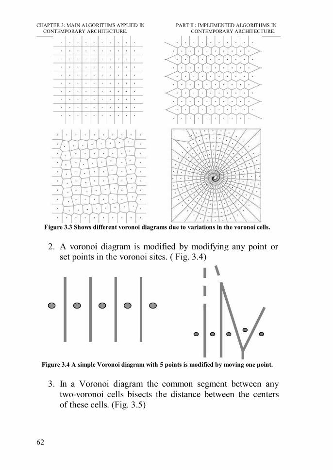
CHAPTER 3: MAIN ALGORITHMS APPLIED IN PART II : IMPLEMENTED ALGORITHMS IN CONTEMPORARY ARCHITECTURE. CONTEMPORARY ARCHITECTURE.
62
Figure 3.3 Shows different voronoi diagrams due to variations in the voronoi cells.
2. A voronoi diagram is modified by modifying any point or
set points in the voronoi sites. ( Fig. 3.4)
Figure 3.4 A simple Voronoi diagram with 5 points is modified by moving one point.
3. In a Voronoi diagram the common segment between any
two-voronoi cells bisects the distance between the centers of these cells. (Fig. 3.5)

PART II : IMPLEMENTED ALGORITHMS IN CHAPTER 3: MAIN ALGORITHMS APPLIED IN CONTEMPORARY ARCHITECTURE. CONTEMPORARY ARCHITECTURE.
63
Figure 3.5 Segments bisect the distances between cells.
4. Naturally Occurring Voronoi ( 3d) : The voronoi geometry is an organizational phenomena that is sometimes referred to as “nature’s rule.” It re-occurs at a variety of scales, materials, and life forms. Different examples are found in biology, mineralogy of formation principles geometry, and construction such as foams, sponges, bone structures and crystals1. (Fig. 3.6)
Figure 3.6 Voronoi diagrams in biology and mineralogy of formation principles, geometry, spatial effect and construction such as foams, sponges, and bone structures.
1 http://www.m-any.org/index.php?option=com_content&task=view&id=14&Itemid=34

CHAPTER 3: MAIN ALGORITHMS APPLIED IN PART II : IMPLEMENTED ALGORITHMS IN CONTEMPORARY ARCHITECTURE. CONTEMPORARY ARCHITECTURE.
64
5. Voronoi diagram in 3d has the following characteristics1:-
- Every 3d cell is defined by one point at its center. - The common face between any two voronoi cells bisects the distance between these cells. -All boulders share a face. -They fit together perfectly. - distributing points in a volume is enough to generate a 3d
voronoi diagram. ( Fig. 3.7) - The 3d voronoi diagram represents a good structural
system since the load distribution is good.
Figure 3.7 Different voronoi diagrams due to the variations in points distribution.
3-2-1-3 Simple Voronoi Algorithm. The following steps is the simplest form of a voronoi algorithm ( in the form of a natural language) 2 :-
1. Take a set of points. 2. Construct a bisector between one point and all the others. 3. The voronoi cell is bounded by the intersection of these
bisectors. 4. Repeat for each point in the set.
1 Aranda, Benjamin/Lasch, Chris, Pamphlet Architecture 27: Tooling(2005),Princeton Architectural Press. P.52 2 Ibid P.53.

PART II : IMPLEMENTED ALGORITHMS IN CHAPTER 3: MAIN ALGORITHMS APPLIED IN CONTEMPORARY ARCHITECTURE. CONTEMPORARY ARCHITECTURE.
65
3-2-1-4 General Applications. A point location data structure can be built on top of the Voronoi diagram in order to answer nearest neighbor queries, where anyone wants to find the object that is closest to a given query point. Nearest neighbor queries have numerous applications. For example, if you want to find the nearest hospital, or the most similar object in a database.
Voronoi diagram is useful in polymer physics. It can be used to represent free volume of the polymer.
It is also used in derivations of the capacity of a wireless network. Informal use of Voronoi diagrams can be traced back to Descartes in 1644. Dirichlet used 2-dimensional and 3-dimensional Voronoi diagrams in his study of quadratic forms in 1850. British physician John Snow used a Voronoi diagram in 1854 to illustrate how the majority of people who died in the Soho cholera epidemic lived closer to the infected Broad Street pump than to any other water pump1
. 3-2-1-5 Architectural Applications. Voronoi diagram lately are becoming useful in architectural design. There are many reasons, which make the voronoi diagram useful in architectural design, for example (Fig. 3.8): a. Their structural properties, both in 2d and 3d. b. As a way to subdivide/organize space, based on proximity/closest neighbor. c. The fact that they can describe many natural formations, like soap bubbles, sponges or bone cells, with their minimal enclosure system of bubbles. d. Its expansion in three dimensions organizes a constructive expansion toward infinity in all directions without any gaps.
1 http://mathworld.wolfram.com/VoronoiDiagram.html

CHAPTER 3: MAIN ALGORITHMS APPLIED IN PART II : IMPLEMENTED ALGORITHMS IN CONTEMPORARY ARCHITECTURE. CONTEMPORARY ARCHITECTURE.
66
Figure 3.8 Methods of applying voronoi diagrams in architecture by starting with
certain points in a volume. The distribution of points is relative to the architectural program requirements. It will be more interesting to use voronoi diagrams in relation to a growing process such as cellular automata or l-systems1. That could produce dynamic voronoi diagrams, and at the same time would be closer to their mathematical/algorithmic nature. Examples:-
1- National Kaohsiung Performing Arts, Kaohsiung, Taiwan. by Zaha Hadid:-
Figure 3.9 Right: the main layout. Left: the stages of generating the layout starting
from the points to the final form. In this project, the architect distributed points in the main envelope to create the main form. The overall form of the building 1 Will be discussed in detail in the following sections.

PART II : IMPLEMENTED ALGORITHMS IN CHAPTER 3: MAIN ALGORITHMS APPLIED IN CONTEMPORARY ARCHITECTURE. CONTEMPORARY ARCHITECTURE.
67
itself seems to grow out of the voronoi patterned landscape, merging at the top, to form a canopy that shades the public plaza below. The main form was created by the Nurbs geometry then it was divided by the voronoi algorithm (Fig. 3.9). 1. (Fig. 3.10-3.12)
Figure 3.10 The main façade of the performing arts center.
Figure 3.11 Various interior pictures represents the entrance and the main hall.
Figure 3.12 The public plaza. constructed from the voronoi diagram.
1 Leen, yun jung and others, Digital diagram architecture + interior (2007), Jeong, Kwang . p.215.

CHAPTER 3: MAIN ALGORITHMS APPLIED IN PART II : IMPLEMENTED ALGORITHMS IN CONTEMPORARY ARCHITECTURE. CONTEMPORARY ARCHITECTURE.
68
2- Water Cube, National Swimming Center, Beijing, China. By PTW architects/John Bilmon:-
Water Cube, Swimming Center, Beijing, China.Water Cube, Swimming Center, Beijing, China.
Figure 3.13 Right: the main building reflects the use of voronoi diagram, Left : using
the envelope to .optimize the building performance.
Figure 3.14 Interior picture shows the surface constructed by a voronoi diagram.
This is a building all about water. Water becomes a profound ‘building material’ that dematerializes the building in a meaningful way. That is the molecular structure of water in its foam state is magnified into the structure of the building in the form of a voronoi diagram. The structure of water softens and dissolves all the boundaries, and gives the sophisticated ‘micro’ details to the monolithic totality. The sophistication of the components and the simplicity and monumentally of the whole gives the building an interesting duality1.(Fig. 3.13,3.14) 1 Ibid p.143.

PART II : IMPLEMENTED ALGORITHMS IN CHAPTER 3: MAIN ALGORITHMS APPLIED IN CONTEMPORARY ARCHITECTURE. CONTEMPORARY ARCHITECTURE.
69
3-2-2 A * Algorithm1 3-2-2-1 Definition. In computer science, A* (pronounced “A star”) is a best-first, graph search algorithm that finds the least-cost path from a given initial node to one goal node (out of one or more possible goals).2 (Fig. 3.15)
Figure 3.15 Examples showing the shortest path between two points selected by an A*
algorithm. It uses a distance-plus-cost function (usually denoted f(x)) to determine the order in which the search visits nodes in the tree. The distance-plus-cost is a sum of two functions: the path-cost function (usually denoted g(x)) and the distance to the goal (usually denoted h(x)). The path-cost function g(x) is the cost from the starting node to the current node. F(x)=g(x)+h(x). Since the h(x) part of the f(x) function must be an admissible heuristic3, it must underestimate the distance to the goal. Thus for an application like routing, h(x) might represent the straight-line
1 The algorithm was first described in 1968 by Peter Hart, Nils Nilsson, and Bertram Raphael. In their paper, it was called algorithm A. Since using this algorithm yields optimal behavior for a given heuristic, it has been called A*. 2 Pearl, Judea (1984). Heuristics: Intelligent Search Strategies for Computer Problem Solving. Addison-Wesley. 3 Heuristic is an adjective for methods that help in problem solving, in turn leading to learning and discovery. These methods in most cases employ experimentation and trial and error techniques. A heuristic method is particularly used to rapidly come to a solution that is reasonably close to the best possible answer, or 'optimal solution'. In more precise terms, heuristics stand for strategies using readily accessible, though loosely ap plicable, information to control problem-solving in human beings and machines

CHAPTER 3: MAIN ALGORITHMS APPLIED IN PART II : IMPLEMENTED ALGORITHMS IN CONTEMPORARY ARCHITECTURE. CONTEMPORARY ARCHITECTURE.
70
distance to the goal, since that is physically the smallest possible distance between any two points (or nodes for that matter). 3-2-2-2 Explanation.
• A* incrementally searches all routes leading from the starting point until it finds the shortest path to a goal. Like all informed search algorithms, it searches first the routes that appear to be most likely to lead towards the goal.
• An example of A star (A*) algorithm in action (nodes are cities connected with roads, h(x) is the straight-line distance to target point). The function for every step is generated.(Fig.3.16)
Figure 3.16 Steps done by an A* algorithm to compare paths from green node (upper right) to blue node (bottom left).1 1 http://en.wikipedia.org/wiki/File:AstarExample.gif , Encyclopedia.

PART II : IMPLEMENTED ALGORITHMS IN CHAPTER 3: MAIN ALGORITHMS APPLIED IN CONTEMPORARY ARCHITECTURE. CONTEMPORARY ARCHITECTURE.
71
• The algorithm traverses various paths from start to goal. For each node x traversed, it maintains 3 values:
g(x): the actual shortest distance traveled from initial node to current node
h(x): the estimated (or “heuristic”) distance from current node to goal
f(x): the sum of g(x) and h(x)
Starting with the initial node, it maintains a priority queue of nodes to be traversed, known as the open set. The lower f(x) for a given node x, the higher its priority. At each step of the algorithm, the node with the lowest f(x) value is removed from the queue, the f and h values of its neighbors are updated accordingly, and these neighbors are added to the queue. The algorithm continues until a goal node has a lower f value than any node in the queue (or until the queue is empty). (Goal nodes may be passed over multiple times if there remain other nodes with lower f values, as they may lead to a shorter path to a goal.) The f value of the goal is then the length of the shortest path, since h at the goal is zero in an admissible heuristic.
3-2-2-3 Simple A* Algorithm. A simple A* algorithm can be summarized and simplified in the following steps :-
1- Start the path by computing the f(x) for the first node in the first path.
2- Calculate the f(x) for the first node in the next path.
3- The lower f(x) value is removed from queue and get a higher priority.
4- Calculate the f(x) for the third node and compare with the node in the step 3.

CHAPTER 3: MAIN ALGORITHMS APPLIED IN PART II : IMPLEMENTED ALGORITHMS IN CONTEMPORARY ARCHITECTURE. CONTEMPORARY ARCHITECTURE.
72
5- Repeat the previous steps 1-3 until the first node representing the main path is selected.
6- The previous steps are repeated for every node in the selected path until the goal is achieved.
3-2-2-4 General Applications. In general, the A* (A-Star) algorithm is used in most games to realize the way finding of game characters. For this purpose, the whole game world is divided into little squares, and for each of these a value is stored, which defines whether the square is easy – more difficult – or impossible to be walked on. (Fig. 3.17)
Figure 3.17 In the two pictures above, the red squares mark regions, where it’s not possible to walk. The blue squares are the data copied and recalculated for the figure which is walking. To find out, which way is the best, some free squares are observed (“expanded” in technical terminology). Those squares are the yellow ones. 3-2-2-5 Architectural Applications. The use of A* algorithms in architecture can be explained as follows1;-
1- Simulating the motion of the users in a certain building, which could help in solving many design problems.(Fig. 3.18) 2- Urban design based on pedestrian’s movement.
Using A* algorithms in urban has proven to be effective in predicting patterns of pedestrian and vehicular movement and 1 http://www.vr.ucl.ac.uk/depthmap/, UCL Bartlett school of Graduate studies.

PART II : IMPLEMENTED ALGORITHMS IN CHAPTER 3: MAIN ALGORITHMS APPLIED IN CONTEMPORARY ARCHITECTURE. CONTEMPORARY ARCHITECTURE.
73
levels of space use in urban areas. Using this technique, the probable outcome of design decisions can be forecasted during the design process. Designs can then be modified so they will achieve levels of movement and space use appropriate to the functions desired on the site, i.e. high levels of movement for retail streets or lower levels for residential ones1. (Fig. 3.18)
Figure 3.18 A* algorithm used in studying circulation in a certain plan. 3-2-3 Stochastic Search 3-2-3-1 Definition: A stochastic search is defined as a random search in space until a given condition is met2.
1 Ibid. 2 Terzidis, Kostas (2006). Algorithmic Architecture. opcit, p.86.

CHAPTER 3: MAIN ALGORITHMS APPLIED IN PART II : IMPLEMENTED ALGORITHMS IN CONTEMPORARY ARCHITECTURE. CONTEMPORARY ARCHITECTURE.
74
Stochastic optimization methods are optimization algorithms which incorporate probabilistic (random) elements, either in the problem data (the objective function, the constraints, etc.), or in the algorithm itself (through random parameter values, random choices, etc.), or in both1. 3-2-3-2 Explanation:
• The implemented Stochastic Process is a search algorithm that iterates over a given spatial structure assigning alleatory architectural elements to specific spots until a set of conditions defined by the rules is met. The alleatory nature of the algorithm is intended to make evident the distinction between the rule-building and a non-deterministic form-making process, therefore showing to what extent in computer-oriented design problem interpretation, rule-building and evaluation are important design acts.
• It shows how a clear division between the rule-building
process and the actual production of form fosters an active dialogue between the computer and the human. The Stochastic Search Algorithm plays the role of the form-maker, whereas the human designer plays the role of the rule-builder and evaluator.
• For example: The placement of toys in a playpen so that
each toy does not overlap another and they all fit within the limits of the playpen can be addressed with a stochastic search. The algorithm will work as follows ( Fig. 3.19);2
While(no more toys left to place){ Choose randomly a position (rx,ry) within the playpen Compare it with all previous toy locations Is there an overlap? ( if no the place the toy at (rx,ry))}
1 Spall, J. C. (2003). Introduction to Stochastic Search and Optimization. Wiley. 2 Terzidis, Kostas (2006). Algorithmic Architecture. opcit, p.87

PART II : IMPLEMENTED ALGORITHMS IN CHAPTER 3: MAIN ALGORITHMS APPLIED IN CONTEMPORARY ARCHITECTURE. CONTEMPORARY ARCHITECTURE.
75
Figure 3.19 Using a stochastic search to distribute toys without any overlaps in a certain area.
This algorithm can be used to place objects within a site so that there is no overlap ( or some other criterion issatisfied).
• Stochastic Search as an optimization method is sometimes
computationally inefficient. It requires a large number of calculations to provide a solution, and the chances of not finding a solution are increased as the search space is reduced.
3-2-3-3 Simple Stochastic Search Algorithm. The following steps represent stochastic search :-
1- Determine the main rules that make the form of a building, such as distributing certain elements in a certain envelope. 2- Start distributing elements, the first element, then the second,…,etc. Each element is distributed by applying the rules and by checking its relation with the previous elements. 3- Test the result and check it form the architectural point of view. 4- If the results do not meet the architectural needs, start again with step 2 until the result meets the needs.
3-2-3-4 Architectural Applications Stochastic search can provide an unlimited number of variations in the architectural form while following the same set of constraints. The interpretation of the problem and the rule setting

CHAPTER 3: MAIN ALGORITHMS APPLIED IN PART II : IMPLEMENTED ALGORITHMS IN CONTEMPORARY ARCHITECTURE. CONTEMPORARY ARCHITECTURE.
76
process play a major role in the production of meaningful form. stochastic search represents the shifting role of human designers from form-makers to rule-builders in a computation-oriented design endeavor. Examples:
1- Accumulata : organizing a certain façade for office building based on stochastic search. By Gyoscope1.
Figure 3.20 Office building façade based on stochastic search.
Stochastic search was used in this example to make an impressive façade by using a certain unit (a box and changing its scale) and this unit is distributed according to certain rules. (Fig. 3.20, 3.21)
1 http://www.gyoscope.com/

PART II : IMPLEMENTED ALGORITHMS IN CHAPTER 3: MAIN ALGORITHMS APPLIED IN CONTEMPORARY ARCHITECTURE. CONTEMPORARY ARCHITECTURE.
77
Figure 3.21 Various iterations for the façade.
2-A Library: generated by the research group of Harvard Graduate School of Design. This project is generated by using a stochastic search to generate the architectural design. Every space is represented as a box and is distributed according to certain architectural functional rules within an area of 30*30 unit square site. The algorithm employs an XY coordinate system that generates a square range to accommodate available positions for the program units. The architectural programs of a library could be satisfied by accumulating a certain number of such modular units, each of them has its uniqueness in X and Y values as a spatial entity and its Z value is determined by the connectivity between each other. So in one program and its subprograms within, or in several programs which share their intimacy, their Z values will be the same thus architecturally being placed on the same floor level. Otherwise, they will be at different levels and connected only by the vertical circulation.1the following diagram shows the program of spaces.
1 Terzidis, Kostas (2006). Algorithmic Architecture. opcit, p.127

CHAPTER 3: MAIN ALGORITHMS APPLIED IN PART II : IMPLEMENTED ALGORITHMS IN CONTEMPORARY ARCHITECTURE. CONTEMPORARY ARCHITECTURE.
78

PART II : IMPLEMENTED ALGORITHMS IN CHAPTER 3: MAIN ALGORITHMS APPLIED IN CONTEMPORARY ARCHITECTURE. CONTEMPORARY ARCHITECTURE.
79
Figure 3.22 Steps in the process of allocating program spaces recursively within a 30 ×
30 unit square site.
Figure 3.23 Library generated by the stochastic search algorithm.

CHAPTER 3: MAIN ALGORITHMS APPLIED IN PART II : IMPLEMENTED ALGORITHMS IN CONTEMPORARY ARCHITECTURE. CONTEMPORARY ARCHITECTURE.
80
3-2-4 L-systems. 3-2-4-1 Definition:
A Lindenmayer System is a formal grammar that was initially conceived as a theory of plant growth. L-Systems can generate complex forms with relatively few simple rules1.
3-2-4-2 Explanation:
1. L-systems are a special kind of string rewriting2 grammars introduced by A.Lindenmayer in 1968 for modeling plants. They rewrite a given string (a sequence of symbols) according to a grammar, i.e. a set of rules. To give an example, the single rule:
a
→ b a b
transforms the string:
a b a c
into
b a b b b a b c
L-Systems consist of two parts: a generative and an interpretative process. The main concept of the generative process is string rewriting, in which the letters that comprise an initial string are replaced by other letters according to pre-defined rules. The replaced letters form a
1 Rozenberg,Grzegorz and Salomaa,Arto . The mathematical theory of L systems,Academic Press, New York, 1980. 2 In computer science and mathematics a Semi-Thue system (also called a string rewriting system) is a type of term rewriting system which covers a wide range of potentially non-deterministic methods of replacing sub-terms of a formula with other terms. What is considered are rewrite systems which, in their most basic form, consist of a set of terms, plus relations on how to transform these terms.

PART II : IMPLEMENTED ALGORITHMS IN CHAPTER 3: MAIN ALGORITHMS APPLIED IN CONTEMPORARY ARCHITECTURE. CONTEMPORARY ARCHITECTURE.
81
new generation of string which is then subject to the established replacement rules. This string rewriting process is usually repeated for several generations.
2. In the second part of the L-System, the letters of one or multiple generations of string are interpreted and visualized. For instance, letters of a string can be visualized by mapping them to attributes of objects or alternatively by interpreting them as turtle graphic commands1.
- For example: A variant of the Koch curve which uses only right-angles.
variables : F
constants : +
−
start : F
rules : (F
→ F+F
−F−F+F)
Here, F means "draw forward", + means "turn left 90°", and - means "turn right 90°" (see turtle graphics).
n = 0:
F
n = 1:
F+F-F-F+F
n = 2:
F+F-F-F+F+F+F-F-F+F-F+F-F-F+F-F+F-F-F+F+F+F-F-F+F
1 Ibid.

CHAPTER 3: MAIN ALGORITHMS APPLIED IN PART II : IMPLEMENTED ALGORITHMS IN CONTEMPORARY ARCHITECTURE. CONTEMPORARY ARCHITECTURE.
82
n = 3:
F+F-F-F+F+F+F-F-F+F-F+F-F-F+F-F+F-F-F+F+F+F-F-F+F+ F+F-F-F+F+F+F-F-F+F-F+F-F-F+F-F+F-F-F+F+F+F-F-F+F- F+F-F-F+F+F+F-F-F+F-F+F-F-F+F-F+F-F-F+F+F+F-F-F+F- F+F-F-F+F+F+F-F-F+F-F+F-F-F+F-F+F-F-F+F+F+F-F-F+F+ F+F-F-F+F+F+F-F-F+F-F+F-F-F+F-F+F-F-F+F+F+F-F-F+F
Figure 3.24 Various generations for Koch Curve.
- Another example:The Sierpinski triangle1 drawn using an L-system. variables : A B constants : +
− 1 http://en.wikipedia.org/wiki/L-systems

PART II : IMPLEMENTED ALGORITHMS IN CHAPTER 3: MAIN ALGORITHMS APPLIED IN CONTEMPORARY ARCHITECTURE. CONTEMPORARY ARCHITECTURE.
83
start : A rules : (A
→ B
−A−B),(B → A+B+A) angle : 60° Here, A and B mean both "draw forward,” + means "turn left by angle,” and
− means "turn right by angle" (see turtle graphics). The angle changes sign at each iteration so that the base of the triangular shapes are always in the bottom (they would be in the top and bottom, alternatively, otherwise). Evolution for n = 2, n = 4, n = 6, n = 9 There is another way to draw the Sierpinski triangle using an L-system. variables : F G constants : +
− start : F
−G−G rules : (F
→ F
−G+F+G−F),(G → GG) angle : 120° F and G both mean "draw forward", + means "turn left by angle", and
− means "turn right by angle".
Figure 3.25 Various generations for Sierpinski triangle.
3. The power of L-Systems as generators of form appears to lie in the extreme reduction of inputs relative to the scope and complexity of the output.

CHAPTER 3: MAIN ALGORITHMS APPLIED IN PART II : IMPLEMENTED ALGORITHMS IN CONTEMPORARY ARCHITECTURE. CONTEMPORARY ARCHITECTURE.
84
4. Much of this power is derived from the fact that inputs can incorporate processes, i.e. there is no formal distinction between the two.
5. While there is no single type of form intrinsic to L-Systems, forms that include branching, recursion, and modularity are particularly easy to construct.
6. L-system structure: The recursive nature of the L-system rules leads to self-similarity and thereby fractal-like forms which are easy to describe with an L-system. Plant models and natural-looking organic forms are similarly easy to define, as by increasing the recursion level the form slowly 'grows' and becomes more complex. Lindenmayer systems are also popular in the generation of artificial life.
3-2-4-3 Simple Algorithm. The following steps represent a simple algorithm for L-systems:
1- Determine the variables that are going to drive the form. Which are Variable, constraints, Rules. 2- Determine the types of mapping that are going to be
assigned to variables. 3- Assign the maps to the variables and start running the
algorithm. 4- Check the evolutions generated. 5- if the resultant form does not meet the specifications go to
step 1 ( change variables or rules). 3-2-4-4 General Applications. As a biologist, Lindenmayer1 worked with yeast and filamentous fungi and studied the growth patterns of various types of algae, such as the blue/green bacteria Anabaena catenula. Originally the L-systems were devised to provide a formal description of the development of such simple multicellular organisms, and to
1 Aristid Lindenmeyer (November 17, 1925 – October 30, 1989) was an Hungarian biologist. In 1968 he developed a formal language that is today called L-systems or Lindenmeyer Systems. Using those systems Lindenmeyer modelled the behaviour of cells of plants. L-systems nowadays are also used to model whole plants.

PART II : IMPLEMENTED ALGORITHMS IN CHAPTER 3: MAIN ALGORITHMS APPLIED IN CONTEMPORARY ARCHITECTURE. CONTEMPORARY ARCHITECTURE.
85
illustrate the neighborhood relationships between plant cells. Later on, this system was extended to describe higher plants and complex branching structures. 3-2-4-5 Architectural Applications: Throughout the history of architecture great interest has been taken in the models for structure that nature offers. This interest can explained through history as follows:- - Stone branched constructions are found in Gothic stone masonry. (Fig. 3.26. (a)) -At the end of the twentieth century, technological advances and research by some architects and engineers has made it possible to build lighter structures as branched constructions on the same bases as those of the natural world. One of the greatest achievements in the fields of architectures are Antonio Gaudi (Fig.3.26. (b)), Frei Otto (Fig. 3.26. (c)), Enric Miralles (Fig. 3.26. (d)), Santiago Calatrava (Fig.3.26. (e)), etc.
Figure 3.26 Various examples for using structure similar to nature structures.

CHAPTER 3: MAIN ALGORITHMS APPLIED IN PART II : IMPLEMENTED ALGORITHMS IN CONTEMPORARY ARCHITECTURE. CONTEMPORARY ARCHITECTURE.
86
L-systems represent mainly the contemporary method for creating architectural forms from nature, especially tree like structure. Nowadays, L- Systems are used to generate an infinite variety of tree like structures and patterns. Example :
1- Inverted skyscraper by Cheng Pan. In this example l-systems are used to generate the structure of the skyscrapers. The idea is to cultivate skyscrapers to create urban clusters (in inside skyscrapers) from a small area on the ground. (Fig. 3.27-3.30)
Figure 3.27 Final elevation for the skyscrapers.
Figure 3.28 Perspective shows the benefits for the inverted skyscrapers (connected urban clusters).

PART II : IMPLEMENTED ALGORITHMS IN CHAPTER 3: MAIN ALGORITHMS APPLIED IN CONTEMPORARY ARCHITECTURE. CONTEMPORARY ARCHITECTURE.
87
Figure 3.29 Structure System for one of the skyscrapers
Figure 3.30 Using L-systems to generate structure ( studying of plans relative to structure)1
1 Leen, yun jung and others, Digital diagram architecture + interior (2007), Opcit . p.305.

CHAPTER 3: MAIN ALGORITHMS APPLIED IN PART II : IMPLEMENTED ALGORITHMS IN CONTEMPORARY ARCHITECTURE. CONTEMPORARY ARCHITECTURE.
88
2- Fake Plastic Trees at the Schindler House, Hollywood,
California, United States. "Fake Plastic Trees" is an attempt to investigate the formal, spatial and atmospheric potential of a vertically sustainable garden in synch with the most advanced technology for plant growth by using l-Systems. The garden is composed of a branching circuitry network made of plastic PVC tubes. These tubes circulate and distribute water with a nutrient solution that cultivates aerial vegetation of different kinds. (Fig. 3.31- 3.33)
Figure 3.31 Fakeplastic trees made from plastic PVC tubes.

PART II : IMPLEMENTED ALGORITHMS IN CHAPTER 3: MAIN ALGORITHMS APPLIED IN CONTEMPORARY ARCHITECTURE. CONTEMPORARY ARCHITECTURE.
89
Figure 3.32 Fakeplastic trees main form.
Figure 3.33 Cross-section showing the flow of water.

CHAPTER 3: MAIN ALGORITHMS APPLIED IN PART II : IMPLEMENTED ALGORITHMS IN CONTEMPORARY ARCHITECTURE. CONTEMPORARY ARCHITECTURE.
90
3-The Grand Egyptian Museum, Giza, Egypt. Heneghan Peng used Sierpinski's system in the design of the translucent alabaster cladding of the front facade of the grand Egyptian museum. (Fig. 3.34)
Fig. 3.34: Sierpinski set was used in designing the translucent alabaster cladding of the grand Egyptian museum's façade.
3-2-5 Cellular Automata 3-2-5-1 Definition. A cellular automaton1 (plural: cellular automata) is a discrete model studied in computability theory, mathematics, theoretical biology and Microstructure Modeling. It consists of a regular grid of cells, each in one of a finite number of states. The grid can be in any finite number of dimensions. Time is also discrete, and the state of a cell at time t is a function of the states of a finite number of cells (called its neighborhood) at time t
−1. These neighbors are
1 In 1970 the concept of the cellular automata was brought to the attention of a wide audience through the introduction of a simple ecological model, called “Game of Life”, by the British mathematician John Horton Conway.

PART II : IMPLEMENTED ALGORITHMS IN CHAPTER 3: MAIN ALGORITHMS APPLIED IN CONTEMPORARY ARCHITECTURE. CONTEMPORARY ARCHITECTURE.
91
a selection of cells relative to the specified cell, and do not change (though the cell itself may be in its neighborhood, it is not usually considered a neighbor). Every cell has the same rule for updating, based on the values in this neighborhood. Each time the rules are applied to the whole grid a new generation is created1.(Fig 3.35)
Figure 3.35 An Eight Neighborhood.
3-5-2 Explanation: 1- Before creating a cellular automata the following points
should be determined :- (Fig. 3.36) - Cells. -State of cells. - Neighborhood of a cell. - Transition rules.
Figure 3.36 Basic cellular automata terminology.
2-One way to simulate a two-dimensional cellular automaton is with an infinite sheet of graph paper along with a set of rules for the cells to follow. Each square is called a "cell" and each cell has two possible states, black and white. The
1 Krawczyk, R.J.: Architectural Interpretation of Cellular Automata. Illinois Institute of Technology, USA, Generative Art 2002.

CHAPTER 3: MAIN ALGORITHMS APPLIED IN PART II : IMPLEMENTED ALGORITHMS IN CONTEMPORARY ARCHITECTURE. CONTEMPORARY ARCHITECTURE.
92
"neighbors" of a cell are the 8 squares touching it. For such a cell and its neighbors, there are 512 (= 29) possible patterns. For each of the 512 possible patterns, the rule table would state whether the center cell will be black or white on the next time interval. The first rule is “game of life” and was stated by John Horton Conway. (Fig. 3.37)
Figure 3.37 Game of life by John Conway1.
3- The three-dimensional universe, of cellular automata
consists of an unlimited lattice of cells. Each cell has a specific state, occupied or empty, represented by a marker recording its location. The transitional process begins with an initial state of occupied cells and progresses by a set of rules to each succeeding generation. The rules determine who survives, dies, or is born in the next generation. The rules use a cell’s neighborhood to determine its future. The neighborhood can be specified in a number of ways. According to the designer need. (Fig 3.38)
1 The rule of the Game of Life is as follows: a dead cellsurrounded by exactly three living cells comes back to life. On the other hand, a living cell surrounded by less than two or more than three neighbours dies, as if by loneliness or overcrowding respectively. In the case of the Game of Life, each cell is affected by the state of its eight neighbours, which are the cells that are directly horizontally, vertically, or diagonally adjacent.

PART II : IMPLEMENTED ALGORITHMS IN CHAPTER 3: MAIN ALGORITHMS APPLIED IN CONTEMPORARY ARCHITECTURE. CONTEMPORARY ARCHITECTURE.
93
Figure 3.38 Game of life by John Conway ( Reproduction Phase)1
3-2-5-3 Simple Algorithm. A simple cellular automata algorithm can be explained in the following steps :- 1- Define the size of the grid. 1 Clarke, Cory & Anzalone, Phillip. Architectural applications of complex adaptive systems, Proceedings of ACADIA Conference 2003.

CHAPTER 3: MAIN ALGORITHMS APPLIED IN PART II : IMPLEMENTED ALGORITHMS IN CONTEMPORARY ARCHITECTURE. CONTEMPORARY ARCHITECTURE.
94
2- Start with certain cells in the grid (based on certain architectural point of view). 3- State the rule defining the next generation. 4- Test the result and make loop of iterations until the result is accepted. 3-2-5-4 General Applications: The general applications for CA can be explained as follows : 1-lattice models for solidification and aggregation structural mechanics. 2-modeling of biological systems. 3-modeling of simple behavior, functioning of organisms, and study of chemical and physical turbulence. 4-study of problems in number theory, tapestry design Forestry. 3-2-5-5 Architectural Applications While cellular automata (CA) were developed originally to describe organic self-replicating systems, their structure and behavior were also useful in addressing architectural, landscape, and urban design problems. From vernacular settlements and social interaction to material behavior and air circulation, CA may provide interesting interpretations of urban and architectural phenomena. The basic idea behind CA is not to describe a complex system with complex equations, but to let the complexity emerge by the interaction of simple individuals following simple rules. Typical feature of CA include: absence of external control (autonomy), symmetry breaking (loss of freedom/heterogeneity), global order (emergence from local interactions), adaptation (functionality/tracking of external variations), complexity ( multiple concurrent values or objectives), and hierarchy ( multiple nested self-organized levels).(Fig 3.39)

PART II : IMPLEMENTED ALGORITHMS IN CHAPTER 3: MAIN ALGORITHMS APPLIED IN CONTEMPORARY ARCHITECTURE. CONTEMPORARY ARCHITECTURE.
95
Figure 3.39 Cellular automata as an LCD display wrapped around a building (class project by N. Anderson for course GSD2311 taught by Kostas Terzidis in Fall 2005 at Harvard University)1 Example; 1- Cero9 examined the generative design potential of cellular automata by applying them to the re-modeling of the northern style housing competition in Aomori/Japan 2001. (Fig. 3.40) shows the adaptation of CA in the design process. (Fig. 3.40, 3.42) shows the final design.
1 Terzidis, Kostas (2006). Algorithmic Architecture. opcit, p.98

CHAPTER 3: MAIN ALGORITHMS APPLIED IN PART II : IMPLEMENTED ALGORITHMS IN CONTEMPORARY ARCHITECTURE. CONTEMPORARY ARCHITECTURE.
96
3.40 CA adaptation into the design process of the housing competition re-modeling.
Fig. 3.41: The final outcome of the northern style housing competition re-modeling
Aomori/Japan 2001 using CA.

PART II : IMPLEMENTED ALGORITHMS IN CHAPTER 3: MAIN ALGORITHMS APPLIED IN CONTEMPORARY ARCHITECTURE. CONTEMPORARY ARCHITECTURE.
97
Fig. 3.42: Variations in outcome.
3-2-6 Swarm Intelligence 3-2-6-1 Definition: Swarm intelligence (SI) is an artificial intelligence based on the collective behavior of decentralized, self-organized systems1. SI systems are typically made up of a population of simple agents interacting locally with one another and with their environment. Although there is no centralized control structure dictating how individual agents should behave, local interactions between such agents lead to the emergence of global behavior. Natural examples of SI include ant colonies, bird flocking, animal herding, bacterial growth, and fish schooling2. 1 The expression was introduced by Gerardo Beni and Jing Wang in 1989, in the context of cellular robotic systems. 2 Aranda, Benjamin/Lasch, Chris, Pamphlet Architecture 27: Tooling(2005),Princeton Architectural Press.

CHAPTER 3: MAIN ALGORITHMS APPLIED IN PART II : IMPLEMENTED ALGORITHMS IN CONTEMPORARY ARCHITECTURE. CONTEMPORARY ARCHITECTURE.
98
Fig. 3.43: Natural examples of SI include ant colonies, bird flocking, and fish schooling.
The application of swarm principles to robots is called swarm robotics, while 'swarm intelligence' refers to the more general set of algorithms. The term swarm is applied to fish, insects, birds and microorganisms, such as bacteria, and describes a behavior of an aggregation of animals of similar size and body orientation, generally cruising in the same direction. This is a partial list of animals that swarm: Ants, Birds, Eels, Honey bees and Termites. The social insect metaphor for solving problems has become a hot topic in the last five years. The number of its successful applications is exponentially growing in combinatorial optimization, communications networks and robotics. More and more researchers are interested in this new exciting way of achieving a form of artificial intelligence based on swarm intelligence (the emergent collective intelligence of groups of simple agents). 3-2-6-2 Explanation: 1- A very influential simulation of bird flocking was published by Craig Reynolds1 in 1987. Reynolds assumed that flocking birds were driven by local forces : -collision avoidance, 1 Craig Reynolds (born March 15, 1953), is an artificial life and computer graphics expert, who created the Boids artificial life simulation in 1986. Reynolds worked on the film Tron (1982) as a scene programmer, and on Batman Returns (1992) as part of the video image crew. He is the author of the OpenSteer library.

PART II : IMPLEMENTED ALGORITHMS IN CHAPTER 3: MAIN ALGORITHMS APPLIED IN CONTEMPORARY ARCHITECTURE. CONTEMPORARY ARCHITECTURE.
99
-velocity matching, -flock centering. - pull away before they crash into one another - try to go the same speed as their neighbors in the flock - try to move toward the center of the flock as these perceive it1. (Fig. 3.44)
Fig. 3.44: Diagram of the swarm. Arrows represent each agent’s heading, dotted lines
their closest neighbors. 3- A typical example of a natural swarm system is an ant colony. Each ant follows only simple local rules, but through the interaction of a large number of ants, the colony as a whole acts like a super-organism: it acquires food, competes for foraging areas, grows, and maintains a highly complex spatial as well as social organization.(Fig.3.45)
Fig. 3.45:Ant Colony as a natural swarm system.
1Pablo Miranda Carranza & Paul Coates, Swarm modeling: The use of Swarm Intelligence to generate architectural form.

CHAPTER 3: MAIN ALGORITHMS APPLIED IN PART II : IMPLEMENTED ALGORITHMS IN CONTEMPORARY ARCHITECTURE. CONTEMPORARY ARCHITECTURE.
100
2- Benefits and Disadvantages of Swarm Systems Benefits: Adaptable, Evolvable, Resilient, Boundless and Novelty Apparent Disadvantages: No-optimal, Non-controllable, Non-predictable, Non-understandable and Non-immediate. 3-2-6-3 Simple Algorithm. Algorithm for Flocking1
- For each agent, for each increment of time : a) Avoid crowding local flockmates. Steer to keep a minimum
distance between each agent and the ones around it.2 b) Align towards the average heading of local flockmates. c) Cohere to the flock, move toward the center mass3 of local
flockmates.(Fig. 3.46)
Fig. 3.46:Main items in creating a flocking algorithm4
. 3-2-6-4 General Applications. The general applications for swarm intelligence can be explained as follows :- 1- The U.S. military is investigating swarm techniques for controlling unmanned vehicles. 2- NASA is investigating the use of swarm technology for planetary mapping. 1 Aranda/Lasch, Tooling, Pamphlet architecture, Princeton Architectural Press, 2006. 2 In flocking models, a boid reacts only to flockmates within a certain neighborhood around itself; there is no global steering intelligence. The neighborhood is defined by a distance from the center of boid and an angle around it, measured from its direction of travel. 3 The "center mass" is the average position of all agents. 4 Ibid.

PART II : IMPLEMENTED ALGORITHMS IN CHAPTER 3: MAIN ALGORITHMS APPLIED IN CONTEMPORARY ARCHITECTURE. CONTEMPORARY ARCHITECTURE.
101
3- A 1992 paper by M. Anthony Lewis and George A. Bekey discusses the possibility of using swarm intelligence to control nanobots1 within the body for the purpose of killing cancer tumors. 4- Artists are using swarm technology as a means of creating complex interactive systems or simulating crowds. Batman Returns was the first movie to make use of swarm technology for rendering, realistically depicting the movements of a group of penguins. 3-2-6-5 Architectural Applications Swarm architecture is a true transarchitecture since it builds new transaction spaces, which are at the same time emotive, transactive, interactive and collaborative. When we look at an urban environment from the point of view of Swarm Architecture we no longer see isolated objects, instead we see objects which have a relation with each other. Swarm-based urban planning is an intriguing and very dynamic design game. It is really challenging for the designer to find the rules that generate excitement in the cities. Swarm intelligence represents an excellent method to test the interaction between the user and the building, to study alternatives of design based on the interactions of users. (Fig. 3.47-3.49)
1 Nanorobotics is the technology of creating machines or robots at or close to the microscopic scale of a nanometres (10-9 metres). More specifically, nanorobotics refers to the still largely hypothetical nanotechnology engineering discipline of designing and building nanorobots. Nanorobots (nanobots, nanoids or nanites) would be typically devices ranging in size from 0.1-10 micrometers and constructed of nanoscale or molecular components. As no artificial non-biological nanorobots have so far been created, they remain a hypothetical concept at this time.

CHAPTER 3: MAIN ALGORITHMS APPLIED IN PART II : IMPLEMENTED ALGORITHMS IN CONTEMPORARY ARCHITECTURE. CONTEMPORARY ARCHITECTURE.
102
Fig 3.47 Paths of pedestrian exploration driven by space syntax architectural concepts based on swarm intelligence1.
Fig. 3.48 Breaking of a corridor doorway into two helps in lane formation and avoid door clogging and oscillation. 1 Space Syntax Architectural tool is used to study circulation based on swarm intelligence and a* algorithm.

PART II : IMPLEMENTED ALGORITHMS IN CHAPTER 3: MAIN ALGORITHMS APPLIED IN CONTEMPORARY ARCHITECTURE. CONTEMPORARY ARCHITECTURE.
103
Fig 3.49 Simulation of a ship evacuation, using the tool EXODUS based on swarm
intelligence. 3-2-7 Genetic Algorithms 3-2-7-1 Definition Genetic Algorithm is an artificial intelligence procedure. It is based on the theory of natural selection and evolution.1
Genetic algorithms were developed in an attempt to explain the adaptive processes of natural systems and to design artificial systems based upon these natural systems. GAs are widely used in optimization of design in many engineering fields, to improve a previous design, or to create new design form scratch. GAs show great power in design fields due to its ability of creating a wide range of alternatives in design, in a 1 Bentley. P.: Evolutionary Design by Computers. Morgan Kaufmann publishers, 1999.

CHAPTER 3: MAIN ALGORITHMS APPLIED IN PART II : IMPLEMENTED ALGORITHMS IN CONTEMPORARY ARCHITECTURE. CONTEMPORARY ARCHITECTURE.
104
very short time, which can help the designer in decision making. The idea of the GAs is based mainly on the genetic rules, similar to the genetic rules of the living creatures.
Fig.3.50 Evolutionary computation has its roots in computer science and evolutionary
biology. GAs are widely used in optimization of design in many engineering fields, to improve a previous design, or to create new design from scratch. GAs show great power in design fields due to its ability of creating a wide range of alternatives in design, in a very short time, which can help the designer in decision making. The idea of the GAs is based mainly on the genetic rules, similar to the genetic rules of the living creatures. 3-2-7-2 Explanation 1- Genetic algorithms use two separate spaces: the search space and the solution space1 (Fig. 3.51).
i. The search space is space of coded solutions to the problem.
ii. The solution space is the space of actual solutions.
Coded solutions, or genotypes must be mapped as actual solutions, or phenotypes, before the quality or fitness of each solution can be evaluated.
1 Ibid.

PART II : IMPLEMENTED ALGORITHMS IN CHAPTER 3: MAIN ALGORITHMS APPLIED IN CONTEMPORARY ARCHITECTURE. CONTEMPORARY ARCHITECTURE.
105
Fig 3.51: Mapping genotypes in the search space to phenotypes in the solution space.
2- In GA each individual element (in the phenotype) in the solution space, takes a code (a binary code depends on its properties) in the search space (in the genotypes). Phenotypes usually consist of collections of parameters; Genotypes consist of coded versions of these parameters. A coded parameter is normally referred as a gene, with the values a gene can be known as alleles. A collection of genes in one genotype is often held internally as a string, and is known as a chromosome (Fig. 3.52, 3.53).
Fig. 3.52: The behavior of the crossover operator. The vertical line shows the position of
the random crossover point.

CHAPTER 3: MAIN ALGORITHMS APPLIED IN PART II : IMPLEMENTED ALGORITHMS IN CONTEMPORARY ARCHITECTURE. CONTEMPORARY ARCHITECTURE.
106
Fig. 3.53: Four generations of evolving house designs using a population
size of four. Parents of the next generation are circled.
3-The use of evolutionary computation by (GAs) to generate designs has taken place in many different fields over the last 20 or 25 years. Designers optimize selected parts of their designs using evolution, artists use evolution to generate aesthetically pleasing forms, architects evolve new building plans from scratch, and computer scientists evolve morphologies and control systems of artificial life1.
In general, these types of evolutionary design by (GAs) can be classified into many categories the most important are as follows: Evolutionary design optimization, Evolutionary art, Evolutionary artificial life forms, and Creative evolutionary design2 (Fig. 3.54).
Fig. 3.54: Classifications of evolutionary design by GAs.
1 Bentley. P.: Evolutionary Design by Computers. Morgan Kaufmann publishers, 1999. op.cit. 2 Ibid, P.35

PART II : IMPLEMENTED ALGORITHMS IN CHAPTER 3: MAIN ALGORITHMS APPLIED IN CONTEMPORARY ARCHITECTURE. CONTEMPORARY ARCHITECTURE.
107
i- Evolutionary Design Optimization( For example, Evolutionary optimization of a table) (Fig. 3.55).
Fig. 3.55: Evolutionary optimization of a table.
ii- Conceptual evolutionary design.
For example, Conceptual evolutionary design of table.(Fig. 3.56).
Fig. 3.56: Conceptual evolutionary design of a table.
iii- evolving artistic tables (Fig. 3.57).

CHAPTER 3: MAIN ALGORITHMS APPLIED IN PART II : IMPLEMENTED ALGORITHMS IN CONTEMPORARY ARCHITECTURE. CONTEMPORARY ARCHITECTURE.
108
Fig. 3.57: Evolving artistic tables.
Iv-Generative evolutionary design of a table (Fig. 3.58)
Fig. 3.58: Generative evolutionary design of a table.
4- GAs spread widely in industrial design but so far slowly in architecture design. One of the famous uses in industry is furniture design. The design criteria id translated into genotypes and the products are left to an autonomous process. After generating sufficient alternatives, form selection can be made according to the user needs, material criteria, or an expert decision. Structural and functional details will be elaborated after the selection. (Fig. 3.59)

PART II : IMPLEMENTED ALGORITHMS IN CHAPTER 3: MAIN ALGORITHMS APPLIED IN CONTEMPORARY ARCHITECTURE. CONTEMPORARY ARCHITECTURE.
109
Fig. 3.59: Generated chairs using 'CongGen' software.
3-2-7-4 Simple Genetic algorithm. The simplest form of a GA is summarized in (Fig. 3.60). This genetic algorithm can be explained in the following points1:
i. The genotype of every individual in the population is initialized with random alleles.
ii. The main loop of the algorithm then begins, with the corresponding phenotype of every individual in the population being evaluated and given a fitness value according to how well it fulfils the problem objective or fitness function.
iii. These scores are then used to determine how many copies of each individual are placed into a temporary area often termed the ‘mating pool’ (i.e. the higher the fitness, the more copies that are made of an individual).
iv. Two parents are then randomly picked from this area. v. Offspring are generated by the use of the crossover
operator, which randomly allocates genes from each parent’s genotype to each offspring’s genotype. For example, given two parents: ‘ABCDEF’ and ‘abcdef’, can create a new generation of ‘ABcdef’ and ‘abCDEF’, and another new generation can be created by ‘ABcdef’ and ‘abCDEF’, and so on…..
1 Ibid.

CHAPTER 3: MAIN ALGORITHMS APPLIED IN PART II : IMPLEMENTED ALGORITHMS IN CONTEMPORARY ARCHITECTURE. CONTEMPORARY ARCHITECTURE.
110
vi. This entire process of evaluation and reproduction then continues until, either a satisfactory solution emerges or the GA will run for more generations.
Fig. 3.60: The simplest genetic algorithm1.
3-2-7-5 Architectural application
The previous types of GA applications (evolutionary design optimization, creative evolutionary design, etc.), can be applied in form finding problems, and in studying alternatives for generating plans.
GA proposed the evolutionary model of nature as the generating process for architectural form. The creative power of natural evolution is done by generating virtual architectural models. Architecture by a GA is considered as a form of artificial life.
The use of genetic algorithms to manufacture forms and relationships is the main process in creating an evolutionary

PART II : IMPLEMENTED ALGORITHMS IN CHAPTER 3: MAIN ALGORITHMS APPLIED IN CONTEMPORARY ARCHITECTURE. CONTEMPORARY ARCHITECTURE.
111
architecture. These genetic algorithms can be used to generate complex spatial models, which can then be filled, punched, and stretched to meet other functional or aesthetic criteria. Architectural concepts in evolutionary architecture are expressed as1: -Generative rules, so that their evolution and development can be accelerated and tested by the use of computer models. Computer models are used to create the development of prototypical forms that are then evaluated on the basis of their performance (or aesthetic) in a simulated environment. The best models become (according to their performance) the parents, which are going to create better models in the new offspring. These new evolutionary steps (offspring) can be generated in a short space of time and the emergent forms are often unexpected. -Genetic language that produces a code script (Genotype at search space) of instructions for form-generation. Example; - Hybrid house (using crossover) In nature, when two individuals mate, each parent passes half of its paired chromosomes onto its common offspring. The chromosomes combine to form new pairs, which lead to a unique new individual with phenotypes inherited from both parents. Individuals with more adapted genotypes will survive in the evolution process while others will eventually be eliminated. Inspired by this nature analog, five building units were designed using the CAD program and exported them into Maya. Then, a program was written in MEL language to execute Genetic
1 Frazer, J., Frazer, J., Liu, XY., Tang, MX. and Janssen, P.: Generative and Evolutionary Techniques for Building Envelope Design. GA2002 (Generative Art and Design Conference, Politecnico di Milano University, Italy , Milan 11-12-13 December 2002).

CHAPTER 3: MAIN ALGORITHMS APPLIED IN PART II : IMPLEMENTED ALGORITHMS IN CONTEMPORARY ARCHITECTURE. CONTEMPORARY ARCHITECTURE.
112
algorithm and produced 3125 offspring in the first generation, by an exhaustive combination of five original units’ genotype. From these 3125 samples, only five ideal spatial arrangement solutions were selected by reviewers and then used as the genotype for the next generation. In the third generation, three nonlinear deformation nodes (bend, twist, and wave) were evolved independently in the evolution and then explicitly added to the five units to yield a more complex layout potential. As a result, a high degree of complexity was generated. In this process, GA demonstrated itself with great power and unlimited potential of form reproduction driven from sets of genetic parameters. The reviewers selected the desired spatial layouts that survived and reproduced them to create the new generation. In the fourth generation, a central courtyard was introduced into the evolution as a “void unit” and blended with the selected layouts. Another input variable, time, as the 4th dimension, was also added to freeze all the layout possibilities into a motion.(Fig. 3.61-3.62).

PART II : IMPLEMENTED ALGORITHMS IN CHAPTER 3: MAIN ALGORITHMS APPLIED IN CONTEMPORARY ARCHITECTURE. CONTEMPORARY ARCHITECTURE.
113
Fig. 3.61: Two generations with their samples.

CHAPTER 3: MAIN ALGORITHMS APPLIED IN PART II : IMPLEMENTED ALGORITHMS IN CONTEMPORARY ARCHITECTURE. CONTEMPORARY ARCHITECTURE.
114
Fig. 3.62: The animation was captured from 3125 spatial arrangement solutions crossed four generations.

PART II : IMPLEMENTED ALGORITHMS IN CHAPTER 3: MAIN ALGORITHMS APPLIED IN CONTEMPORARY ARCHITECTURE. CONTEMPORARY ARCHITECTURE.
115
3-2-8 Examples for other kinds of algorithms. 3-2-8-1 cracking This algorithm divides a certain objects to smaller particles by cracking it. By recalling its source shape recursively, cracking generates a geometry of self-similarity. For instance, a river delta has variously scaled “triangles” that are each “cracked” by the iterative and aggregate process of fluvial erosion. The crack patterns in dry mud or paint show a similar recursion of shapes in at least two visible scales. Whether it is the dynamics of water channeling through sediment to produce a delta or heat and dryness causing paint to peel, cracking is a distinct action performed through materials. ( Fig. 3.63)
Fig. 3.63:Natural cracks found in nature.
- Simple Algorithm for Cracking1 ( Fig. 3.64) 1. Choose a shape to be cracked. 2. Find its centroid. 3. Create subsidiary shapes by connecting the centroid to each end
of one edge of the parent shape. 4. Repeat steps 2 and 3 for each new shape.2 5. Continue until a limit is reached. Choose an iteration of the
1 This algorithm produces a construction in which each edge is shared by exactly two shapes and each edge is continuous—connected to an edge which is connected to an edge, and so on—no matter how dense the mesh becomes. 2 If one were to localize the cracking—crack more in one part of the structure than another—one could create patches made up of a higher number of shorter members.

CHAPTER 3: MAIN ALGORITHMS APPLIED IN PART II : IMPLEMENTED ALGORITHMS IN CONTEMPORARY ARCHITECTURE. CONTEMPORARY ARCHITECTURE.
116
algorithm whose subsidiary shapes will be left whole.1
Fig. 3.64:Steps for cracking a certain object.
The cracking algorithm used in these sketches is one that takes a shape and divides it according to a value set by the user. In each instance, the shape is being recurred to another set of self-similar shapes. 2.(Fig.3.65)
Fig. 3.65 Cracked objects by using the cracking the algorithm.
1 Each iteration contains an exponentially greater number of shapes than the one before it. Each iteration takes an exponentially longer time to process. 2 Aranda/Lasch, Tooling, Pamphlet architecture, Princeton Architectural Press, 2006, Opcit.

PART II : IMPLEMENTED ALGORITHMS IN CHAPTER 3: MAIN ALGORITHMS APPLIED IN CONTEMPORARY ARCHITECTURE. CONTEMPORARY ARCHITECTURE.
117
3-2-8-2 Packing Packing is a powerful organizational method in which an element’s position in regard to its neighbors is determined by certain rules—not too close, no overlapping, etc. Packing encourages a sense of democracy where one element’s inclusion implies either an understanding of every other element or possibly a readjustment of the entire population. Whether it is studied as self-organized structuring in cells or as a behavioral trope in crowds, packing can be observed as a collective and emergent sense of space—close, but not too close.(Fig. 3.66) -Simple Algorithm for Packing 1.Create a shape1 of a random size. 2.Pick a random point. 3. a) If the shape is inside another shape2, or overlaps another shape, throw it away and go back to step 13
b) If not, place it. Go to step 1.
Fig. 3.66 Oscillatory packing.
1 Spheres (circles) are naturally stable shapes. When packed together, they create a very strong construction, owing to the sphere’s inherent stability and tendency for a collection of spheres to produce multiple points of tangency. 2 If the distance between the circles is less than the suns of their radii, then they overlap. 3 Obviously, as more circles are placed, it gets harder and harder to place a new one. This is a brute force method.

CHAPTER 3: MAIN ALGORITHMS APPLIED IN PART II : IMPLEMENTED ALGORITHMS IN CONTEMPORARY ARCHITECTURE. CONTEMPORARY ARCHITECTURE.
118
Beyond serving as a dynamic system for producing flat organizations, packing also offers rich three-dimensional and material strategies when combined with other operations. (Fig. 3.67)
Fig. 3.67 Various forms generated by packing.
3-2-8-3 Spiraling Whether stars, storm clouds, or petals of a flower, the spiral is only detectable by observing the things caught in its wake. Droplets of Ferro-liquid placed in a polarized solution reveal that magnetic energy naturally distributes itself in a spiral manifestation. The form is also inherent in plant growth patterns, which allow the maximum number of petals to grow in the least amount of space. The spiral is not so much a shape as the evidence of a shape in formation. (Fig. 3.68)

PART II : IMPLEMENTED ALGORITHMS IN CHAPTER 3: MAIN ALGORITHMS APPLIED IN CONTEMPORARY ARCHITECTURE. CONTEMPORARY ARCHITECTURE.
119
Fig. 3.68 spiral as a path for objects.
Fig. 3.69 Parameters for generating a spiral.
Simple algorithm for Spiraling (Fig. 3.69):
1. Pick an angle (d). 2. imagine a circle. Plot one point on this circle at d degrees from the origin.1 3. Plot another point at d degrees from the last point on a concentric circle that is slightly bigger than the circle before it. 4. Repeat step 3.2
1 The coordinates of the kth point in a spiral lattice with divergence d and expansion
parameter G are given by (Gk cos(kd), Gk sin(kd)). 2 In a spiral lattice, the eye tends to connect nearest points into spirals. These spirals within the spiral arc called parastichies. In plants, the number of d=137.5 these visible spirals are most often two successive elements of the Fibonacci sequence: one in which each number is the sum of the previous two.

CHAPTER 3: MAIN ALGORITHMS APPLIED IN PART II : IMPLEMENTED ALGORITHMS IN CONTEMPORARY ARCHITECTURE. CONTEMPORARY ARCHITECTURE.
120
A series of points placed on concentric circles with a constant divergence angle between them is called a spiral lattice. These experiments use a three-dimensional spiral lattice to project a structured envelope. The spiral lattice is promising as a formal proposition because there is a seemingly infinite number of spiral/sub-spiral configurations available from the finite set of shared points plotted in the original lattice. Within any of these configurations it is easy to find multiple points of intersection to develop stability. (Fig. 3.70)
Fig. 3.70 Examples for spirals generated by the algorithm.
3-2-8-4 Weaving. Weaving is the synthesis of two different systems, interlocking in order to give self-supporting form to their combined whole. Traditionally referred to as a “warp” and a “weft” pattern, neither could support themselves alone, but together they become strong. The endless variety of weaving seen in basket, net, rope, and textile design proves that procedural techniques and cultural practices are not mutually exclusive. Most surprising about a woven construction is that it is actually harder to unravel than to weave in the first place. (Fig. 3.71)
This model is typically used to describe Phyllotaxis (Greek phyio, leaf + taxis, arrangement), a naturally occurring plant growth pattern that governs the arrangement of leaves, flower petals, pine cones, etc.

PART II : IMPLEMENTED ALGORITHMS IN CHAPTER 3: MAIN ALGORITHMS APPLIED IN CONTEMPORARY ARCHITECTURE. CONTEMPORARY ARCHITECTURE.
121
Fig. 3.71 Various types for weaving.
Simple algorithm for Weaving1 1. Start drawing a sin curve: a line that goes around a circle at a steady rate, spread out over time.2 2. Loop the curve by adding a term—a mathematical function, like cos ()—that speeds up and slows down the line as it goes around the circle.3 3. Add more terms to create more loops, overlaps, and squiggles. 4. Mirror the curve for a denser, interlocking figure.4 These sketches use a parametric equation to organize a series of sine and cosine curves in space. The weave is a crossing pattern, a “soft” structure of loops and knots wherein the shape of the construction is determined less by the properties of the materials themselves than by the pattern through which two sets of materials interact.(Fig.3.71)
1 Ibid 2 The components of the equation are scale, frequency, and amplitude. These mathematical attributes replace the traditional knotmaking procedures of translation, turning, and reflection. Either one of these sets of attributes can produce an endless variety of forms that are traceable back to simple rules. 3 Adding a cos ( ) term in the x portion of the equation affects the horizontal expansion of the points that make up the curve. The x term pushes or pulls these points along the “time’ line (t) until the curve begins to loop back on itself. Adding a z term gives a three-dimensional aspect to the curve. 4 Many traditional weaving patterns make use of symmetry because it provides guaranteed points of overlap that help to structure the weave.

CHAPTER 3: MAIN ALGORITHMS APPLIED IN PART II : IMPLEMENTED ALGORITHMS IN CONTEMPORARY ARCHITECTURE. CONTEMPORARY ARCHITECTURE.
122
Fig. 3.72 Forms generated by weaving algorithm.

PART II : IMPLEMENTED ALGORITHMS IN CHAPTER 3: MAIN ALGORITHMS APPLIED IN CONTEMPORARY ARCHITECTURE. CONTEMPORARY ARCHITECTURE.
123

CHAPTER 3: MAIN ALGORITHMS APPLIED IN PART II : IMPLEMENTED ALGORITHMS IN CONTEMPORARY ARCHITECTURE. CONTEMPORARY ARCHITECTURE.
124

PART II : IMPLEMENTED ALGORITHMS IN CHAPTER 3: MAIN ALGORITHMS APPLIED IN CONTEMPORARY ARCHITECTURE. CONTEMPORARY ARCHITECTURE.
125
-Conclusion - The following methods can support running algorithms for architectural design: using Scripting languages, or Embedded programming languages, or external programming language - Many algorithms are applied in contemporary architecture. The following diagram shows these algorithms :-
Algorithms applied in contemporary architecture
I- Special algorithms (about infinity) designed for certain designs or problems.
II-Most popular algorithms used in contemporary architecture.
Voronoi Algorithm
A* Algorithm
Stochastic Search
L-Systems
Cellular Automata
Swarm Intelligence
Genetic Algorithms

PART II:MAIN ALGORITHMS APPLIED IN CHAPTER 4: APPLICATIONS OF CONTEMPORARY ARCHITECTURE. ALGORITHMS IN ARCHITECTURE
127
CHAPTER 4:
APPLICATIONS OF ALGORITHMS IN ARCHITECTURE.

CHAPTER 4: APPLICATIONS OF PARTII: MAIN ALGORITHMS APPLIED IN ALGORITHMS IN ARCHITECTURE. CONTEMPORARY ARCHITECTURE.
128

PART II:MAIN ALGORITHMS APPLIED IN CHAPTER 4: APPLICATIONS OF CONTEMPORARY ARCHITECTURE. ALGORITHMS IN ARCHITECTURE
129
CHAPTER 4:
APPLICATIONS OF ALGORITHMS IN
ARCHITECTURE What method, what system, does an architect use to design a building? how are programmatic needs and context- with their degrees of freedom and constraints – translated into architectural design? Regardless of their complexity, the tasks and decisions involved can be formalized as an algorithm. As such, algorithms provide a framework for articulating and defined both input data and procedures. This formalization can promote structure and coherency, while systematically maintaining full traceability of all input data. In recent years, algorithms in architecture have been able to go beyond their role as frameworks of formalization and abstraction. This has been made possible in a large part by the integration of scripting language into CAD programs. Algorithms' output can now be directly visualized, enabling their use as a generative design tool. Since algorithms provide the benefits of scalability and premutability, multiple variations of a scheme are easily generated. A slight change of inputs or process leads to an instant adaptation of output. Algorithms' generative processes can further be enhanced by evaluation procedures to enable an automated optimization. A large number of algorithms can be used in architecture ( about infinity). The algorithms already discussed in the previous chapter (the most famous) in addition to any other algorithms designed for special design needs.

CHAPTER 4: APPLICATIONS OF PARTII: MAIN ALGORITHMS APPLIED IN ALGORITHMS IN ARCHITECTURE. CONTEMPORARY ARCHITECTURE.
130
All algorithms applied in architecture (about infinity) can be classified according to their applications in architectural design into five applications. The following chapter will discuss the five approaches of using algorithms in architecture, ranging from their function as simulation and optimization tools to their development as a generative design language1. These approaches are as follows:-
1- Generation. 2- Permutation. 3- Optimization. 4- Simulation. 5- Transformation.
The discussion is going to be mainly through examples of applying algorithms in certain problems in architectural design. 4-1 Generation. The algorithm in this case generates design from scratch. The generated design is based on the type of algorithm used and its rule. The generation algorithms can generate alternatives for the design functions. (either forms or plans) Generation is the most popular application of using algorithms due to the capability of algorithms to generate stunning forms with simple codes. 4-1-1 algorithms used in generation. The algorithms used in generating a design are : - for generating forms : Voronoi, Cellular automata, stochastic search, L-systems, …etc. (nearly most of the algorithms) 1 Hansmeyer, Micheal, Algorithms in architecture,http://www.mh-portfolio.com/indexH.html.

PART II:MAIN ALGORITHMS APPLIED IN CHAPTER 4: APPLICATIONS OF CONTEMPORARY ARCHITECTURE. ALGORITHMS IN ARCHITECTURE
131
- for generating function (plans) : Interactive genetic algorithms, or stochastic search. 4-1-2 Generating architecture design. The following examples represent good examples for generating an architectural design ( will be discussed in details) :-
1- Generating a transportation node and shopping mall downtown, St. Louis, Greece by Dimitris Gourdoukis.
2- Generating a high rise building. 4-1-2-1 Transportation node + Shopping mall downtown St. Louis., Greece, 2007-2007, by Dimitris Gourdoukis. The process that will be described is employed in the design of a transportation node and shopping mall downtown St. Louis. The ‘node’ connects two metro stations and the train station and at the same time hosts a shopping mall. The building is developed as an analogy for the human body (Organs, bones,and skin):-
- Organs become the enclosed spaces. - The bones become the structure system. - The skin becomes the outer membrane.
The project is employing the latest building technology with a fiber-carbon structure and ETFE pillows for the outer skin1. In this example, a cellular automaton script is used with the voronoi algorithm to generate the form. This example shows two algorithms used to generate the project. ( Fig. 4.1) 1http://www.worldarchitecture.org/world-buildings/world-buildings-detail.asp?position=detail&country=Greece&no=2432 at 10-2-2009

CHAPTER 4: APPLICATIONS OF PARTII: MAIN ALGORITHMS APPLIED IN ALGORITHMS IN ARCHITECTURE. CONTEMPORARY ARCHITECTURE.
132
Figure 4.1 Exterior perspective for the final form.
The process used in developing the project can be summarized in the following steps :
a. 2d cellular automaton script is executed, with a random or pre-defined initial configuration of cells. (Fig. 4.2-4.3)

PART II:MAIN ALGORITHMS APPLIED IN CHAPTER 4: APPLICATIONS OF CONTEMPORARY ARCHITECTURE. ALGORITHMS IN ARCHITECTURE
133
Figure 4.2 Automaton cells generation (1-6).

CHAPTER 4: APPLICATIONS OF PARTII: MAIN ALGORITHMS APPLIED IN ALGORITHMS IN ARCHITECTURE. CONTEMPORARY ARCHITECTURE.
134
Figure 4.3 Automaton cells generation (7-10).
b. Every generation of the CA is stacked on top of the previous one creating a 'progression' for the active cells. (Fig. 4.4-4.6)
Fig 4.4 The previous generated Automaton cells.

PART II:MAIN ALGORITHMS APPLIED IN CHAPTER 4: APPLICATIONS OF CONTEMPORARY ARCHITECTURE. ALGORITHMS IN ARCHITECTURE
135
Fig 4.5-4.6 Connecting the cellular cells together.
c. The centers of the active CA cells are used in order to generate
the voronoi diagram. The limit of that diagram is defined by the limits of the outer active cells of each generation of the CA. (Fig 4.7-4.9)
Fig 4.7 Generating the voronoi diagram from the cellular cells.

CHAPTER 4: APPLICATIONS OF PARTII: MAIN ALGORITHMS APPLIED IN ALGORITHMS IN ARCHITECTURE. CONTEMPORARY ARCHITECTURE.
136
Fig 4.8-4.9 Smoothing the voronoi diagram.
d. The edges of the voronoi cells are used as the structural system. (Fig. 4.10-4.11)
Fig 4.10 Successive sections show the generated voronoi diagram.

PART II:MAIN ALGORITHMS APPLIED IN CHAPTER 4: APPLICATIONS OF CONTEMPORARY ARCHITECTURE. ALGORITHMS IN ARCHITECTURE
137
Fig 4.11 Section shows the generated voronoi diagram.
d. A smoothed version of the voronoi cells is used in order to
define enclosed space. (Fig. 4.12-4.16)
Fig.4.12 Final form shows the generated smoothed voronoi.
Fig.4.13-4.14 Final form shows the generated unit and interior shot.

CHAPTER 4: APPLICATIONS OF PARTII: MAIN ALGORITHMS APPLIED IN ALGORITHMS IN ARCHITECTURE. CONTEMPORARY ARCHITECTURE.
138
Fig.4.15 Escalator surrounded by the voronoi diagram.
4-1-2-2 Generating a high rise building. This tower is created using certain algorithms based on Voronoi diagram1. In the tower, the created 3d polygons represent the architectural spaces which will be used in the project.
The design is generated through the following steps:- stage one: Specifying the Voronoi points in 3d based on the design program, and the context. ( Many studies were done to study the generated points relative to the site entrance, orientation,..etc).(Fig. 4.16-4.18) 1 Voronoi is the partitioning of a plane with points (The initial set of points that is in this project is based on program requirements) into convex polygons such that each polygon contains exactly one generating point and every point in a given polygon is closer to its generating point than to any other.

PART II:MAIN ALGORITHMS APPLIED IN CHAPTER 4: APPLICATIONS OF CONTEMPORARY ARCHITECTURE. ALGORITHMS IN ARCHITECTURE
139
Fig.4.16-4.17 Specifying the points in space to generate the form based on Voronoi
diagram.
Fig.4.18 Studying the form relative to the context.
stage two: Smoothing the outlines of the tower created from the voronoi diagram. (Fig.4.19)
Fig.4.19 Smoothing the outline of the tower.

CHAPTER 4: APPLICATIONS OF PARTII: MAIN ALGORITHMS APPLIED IN ALGORITHMS IN ARCHITECTURE. CONTEMPORARY ARCHITECTURE.
140
stage three: Studying the architectural spaces created and the generated voronoi diagram. (Fig. 4.20-4.21)
Fig.4.20-4.21 Studying the generated spaces.
Fig.4.22 Clusters generated by voronoi cells resembles the relation of bones to organs. The edges of the voronoi cells become the structure, while the voronoi cells are used (in a 'smoothed' version) as clusters of spaces in a configuration that resembles the relation of bones to organs.(Fig. 4.22) stage four: Depicting the final form. (Fig. 4.23-4.24)

PART II:MAIN ALGORITHMS APPLIED IN CHAPTER 4: APPLICATIONS OF CONTEMPORARY ARCHITECTURE. ALGORITHMS IN ARCHITECTURE
141
Fig.4.23 Final form for the building.
Fig.4.24 Main Façade for the building.

CHAPTER 4: APPLICATIONS OF PARTII: MAIN ALGORITHMS APPLIED IN ALGORITHMS IN ARCHITECTURE. CONTEMPORARY ARCHITECTURE.
142
4-2 Permutation In permutations, the algorithms used in this case generate permutations for the design without optimizing the design. Usually permutations are used to study wide range of alternatives to make the architect take decisions in his design. Permutations are mostly applied in architectural design through creating alternatives for the forms, or by creating alternatives for the plans. Permutations are used to generate only alternatives without any optimization. 4-2-1 Algorithms used in Permutation. Algorithms used in permutations are mainly interactive genetic algorithms1, and any other algorithms used with iterations (such as stochastic search, and generation algorithms with iterations). 4-2-2 Permutations in architectural design. In the following section, examples for using permutations in architecture will be explained, these examples are as follows :-
1- Making permutations for a certain plan. 2- A residential tower ( by the design studio of Columbia
university in the USA). 3- Great court roof museum, London, UK, by Norman Foster. 4- Serpentine pavilion, London, UK, by Toyo Ito.
1 An interactive genetic algorithm (IGA) is defined as a genetic algorithm that uses human evaluation. These algorithms belong to a more general category of Interactive evolutionary computation. The main application of these techniques include domains where it is hard or impossible to design a computational fitness function, for example, evolving images, music, various artistic designs and forms to fit a user's aesthetic preferences. Interactive computation methods can use different representations, both linear (as in traditional genetic algorithms) and tree-like ones (as in genetic programming).

PART II:MAIN ALGORITHMS APPLIED IN CHAPTER 4: APPLICATIONS OF CONTEMPORARY ARCHITECTURE. ALGORITHMS IN ARCHITECTURE
143
4-2-2-1 Making permutations for a certain plan. 1 This example will discuss the use of an Interactive Genetic Algorithm to make permutations for a house plan.
A house is considered to be composed of a number of zones, such as living zone, entertainment zone, bed zone, utility zone, etc. Each zone is composed of a number of rooms (or spaces), such as living room, dining room, bedroom, hall, bathroom, etc. Each room is composed of a number of space units. Generally, in a design such as a house, the space unit will be constant. The scale (level of abstraction) of the space unit depends on the precision required in differences between various possible room sizes. The smaller the unit, the longer the genotype for a given size of room but the greater the shape alternatives. But first some criteria must be described for a thorough understanding. - The Design Grammar In this example, the generation of spaces, basically comes down to locate spatial component units for that level. At the room level, the component unit is a fundamental unit of space. At the zone level, the component unit is a room and at the house level the component unit is a zone2. The design grammar used here is based on the method for constructing polygonal shapes represented as closed loops of edge vectors3. The grammar is based on a single fundamental rule which states that any two polygons, Pi and Pj, may be joined through the conjunction of negative edge vectors, V1 and V2, (equal in magnitude and opposite in direction). The conjoining of 1 Rosenman, M.A. and Gero, J.S.: Evolving Designs by Generating Useful Complex Gene Structures. In P. Bentley (ed.), Evolutionary Design by Computers, Morgan Kaufmann, London, pp. 345-364. 1999. 2 Ibid. 3 Rosenman, M. A. (1995). An edge vector representation for the construction of 2- dimensional shapes, Environment and Planning B:Planning and Design, 22:191-212.

CHAPTER 4: APPLICATIONS OF PARTII: MAIN ALGORITHMS APPLIED IN ALGORITHMS IN ARCHITECTURE. CONTEMPORARY ARCHITECTURE.
144
these vectors results in an internal edge and a new polygon, Pk. This rule ensures that new cells are always added at the perimeter of the new resultant shape. The fundamental conjoining rule can be specialized for different types of geometries. Orthogonal geometries are based on the following four vectors of unit length: W = (1, 90), N = (1, 0), E = (1, 270), S= (1, 180) so that the two pairs of negative vectors are N - S and E - W. These two pairs of negative vectors allow for the generation of all polyminoes. Orthogonal geometries will be used in this example without loss of generality. Other (sub) rules may be formed for other geometries.(Fig.4.25) - Genotype and Phenotype
A polygon is described by its sequence of edge vectors. A suffix is used to identify individual edges of the same vector type. Thus, the square cell is described as (W1, N1, E1, S1). The sequence of edge vectors for a shape is the phenotype providing the description of that shape’s structure. The genotype for any generated polymino is the sequence of the two subshapes (polyminoes) used and the two edges joined. An example of the generation of a trimino is shown in1 (Fig. 4.25). Figure 4.25 shows a basic unit or cell, P1, which provides a starting point for the generation of polyminoes. Each generated shape is accompanied by its genotype and phenotype. The generation of these polyminoes occurs from a random selection of edges in the first shape conjoined with a random selection from equal and opposite edges in the second shape. At each step in the generation, the phenotype is reinterpreted to generate a new edge vector description and the conjoining (sub) rules applied. The genotype for the generated trimino is given as (P2, P1, N2|S1). This can be expanded as ((P1, P1, E1|W1), P1, N2|S1).

PART II:MAIN ALGORITHMS APPLIED IN CHAPTER 4: APPLICATIONS OF CONTEMPORARY ARCHITECTURE. ALGORITHMS IN ARCHITECTURE
145
When the same units are used for generation, the unit can be omitted and the genotype represented as the sequence of edge vector conjoining. That is P3(g) = (E1|W1, N2|S1). The length of the genotype depends on the size of the polymino to be generated, that is on the area of the polymino. This corresponds to required room sizes.
Fig. 4.25: Generation of a Trimino.( Each generated shape is accompanied by its
genotype and phenotype). Once a population of different rooms is generated for each room type in a given zone, the zone can be generated through the conjoining of rooms in a progressive fashion. Because of the cell-type structure of the polygons, the conjoining may occur at any appropriate pair of cell edges. Therefore, a large number of possible zone forms can be generated from two rooms. An example of some possibilities arising from the conjoining of two polyminoes is given1. (Fig. 4.26)
Fig. 4.26: Some Examples of Conjoining Two Polyminoes.
1 Ibid.

CHAPTER 4: APPLICATIONS OF PARTII: MAIN ALGORITHMS APPLIED IN ALGORITHMS IN ARCHITECTURE. CONTEMPORARY ARCHITECTURE.
146
The two polyminoes, P1 and P2, represent instances of two different room types and the polyminoes resulting from the joining of the two rooms represent instances of a particular zone type. When one pair of edges are conjoined other edges may also be conjoined, e.g. P4, P5 and P6. In the case of overlap, as in P6, the resultant shape is discarded. The same process used for generating zones is used to generate houses. The joining of different instances of different zone types generates different instances of houses. The above grammar can be used to generate initial populations for each level in the spatial hierarchy. Each such initial population is then evolved, as necessary, so that solutions are ‘adapted’ to design requirements1. - The Evaluation Criteria ( Fitness Functions). At each level, different fitness functions apply according to the requirements for that level. While the requirements for designs of houses involve many factors, many of which cannot be quantified or adequately formulated in a fitness function2, some simple factors have been used initially to test the feasibility of the approach. For this example, the fitness function for rooms consists of minimizing the perimeter to area ratio and the number of angles. This requirement tends to produce compact forms, useful as rooms. For zones, the fitness function consists of minimizing a sum of adjacency requirements between rooms reflecting functional requirements. At the house level, the fitness function consists of minimizing a sum of adjacency requirements between rooms in one zone and rooms in other zones. This has the tendency to select those arrangements of zones where adjacency interrelations are required 1 Ibid. 2 For this reason the used genetic algorithm is classified as Interactive Genetic Algorithm.

PART II:MAIN ALGORITHMS APPLIED IN CHAPTER 4: APPLICATIONS OF CONTEMPORARY ARCHITECTURE. ALGORITHMS IN ARCHITECTURE
147
between rooms of different zones. In addition to these quantitative assessments, qualitative assessments will be made subjectively and interactively by a user/designer (because it is Interactive genetic algorithm). The aim is to direct the evolutionary process to produce populations of good solutions either as components for higher levels or at the final level itself. So that, even though the global optimum solution for the shape of a room using the above criteria, may be known, this may not be the optimum solution at the zone and house levels. By selecting other non-optimal but good solutions, according to the given criteria, good unexpected results may be achieved for the overall design1. - Propagation ( Crossover).
Simple crossover is used for the production of 'child' members during the evolution process. Looking first at the room level to see the effect of such a crossover process, crossover can occur at any of the four sites as shown in (Fig. 4.27 a) with two results as shown in (Fig. 4.27 b). Since the cells are always of the same space unit, the cell identification in the genotype representation has been omitted for simplicity2.
1 Ibid. 2 Ibid.

CHAPTER 4: APPLICATIONS OF PARTII: MAIN ALGORITHMS APPLIED IN ALGORITHMS IN ARCHITECTURE. CONTEMPORARY ARCHITECTURE.
148
Fig. 4.27: Crossover at Room Level; (a) initial rooms R1 and R2 generated
from unit square cell U1, (b) crossover at site 4. At the zone level, crossover occurs as shown in (Fig. 4.28). Two initial instances of living zones, Z1 and Z2 are shown in (Fig. 4.28 a). Each zone has one instance of each of living room, dining room and entrance. (Fig. 4.28 B) shows crossover for one of the four possible sites. A similar process is followed at the house level.
Fig. 4.28: Zone Crossover; (a) rooms and initial zones, Z1 and
Z2, (b) crossover at Site 2.

PART II:MAIN ALGORITHMS APPLIED IN CHAPTER 4: APPLICATIONS OF CONTEMPORARY ARCHITECTURE. ALGORITHMS IN ARCHITECTURE
149
- Implementations A computer program written in C++ and Tcl-Tk under the Sun Solaris environment has been implemented using the simple criteria described previously. Each evolution run, for all levels, tends to converge fairly quickly to some dominant solution. Rather than use a mutation operator to break out of such convergence, it was found that a more efficient strategy was to generate multiple runs with different initial randomly generated populations. This produces a variety of gene pools thus covering a more diverse area of the possible design space. Users can nominate the population size, number of generations for each run and select rooms, zones and houses from any generation in any run as suitable for final room, zone or house populations. These selections are made interactively by users as solutions appear which are judged favorable, based perhaps on factors not included in the fitness function. Such selections may therefore not be optimal according to the given fitness function1. Results are shown in the following figures (Fig. 4.29 – Fig. 4.32) for room, zone and house generation.
Fig. 4.29: Results of Living Room Generation after the 17th generation ( The left side
shows the solutions selected by the architect). 1 Ibid.

CHAPTER 4: APPLICATIONS OF PARTII: MAIN ALGORITHMS APPLIED IN ALGORITHMS IN ARCHITECTURE. CONTEMPORARY ARCHITECTURE.
150
Fig. 4.30: Results of Living Zone Generation.
Fig. 4.31: Results of Bed and Living zones Generation.

PART II:MAIN ALGORITHMS APPLIED IN CHAPTER 4: APPLICATIONS OF CONTEMPORARY ARCHITECTURE. ALGORITHMS IN ARCHITECTURE
151
Fig. 4.32: Results of House Generation. (Fig. 4.29) shows the 17th generation of the evolution of this population of 60 members. A fifth room shape was selected at the 14th generation and two more room shapes (Room Numbers 1 and 41) are being selected. The upper line in the graph shows the evolution of the best solution while the lower line shows the evolution of the population average. Other rooms were generated in a similar way. The room areas generated were: (a) Living Zone: Living Room 24; Dining Room 15; Kitchen 9; Entrance 4; (b) Bedroom Zone: Master Bedroom 15; Bedroom 12; Bathroom 6; Hall 3. (Fig. 4.28) shows the results of the Living Zone generation. The initial population of 50 Living Zones at run 1 was randomly generated by selecting rooms from the final selections for the Living Room, Dining Room, Kitchen and Entrance. Twenty Living Zones have been selected by the user. (Fig. 4.31) shows the set of Bedroom and Living Zones selected. (Fig. 4.32) shows the final set of houses generated in this example.

CHAPTER 4: APPLICATIONS OF PARTII: MAIN ALGORITHMS APPLIED IN ALGORITHMS IN ARCHITECTURE. CONTEMPORARY ARCHITECTURE.
152
4-2-2-2 A residential tower ( by the design studio of Columbia university in the USA). This project explores generating permutations through algorithms. It examines how a fixed process with fixed rules can produce heterogeneous variants through adjustment in the values of its outputs. Two approaches are considered. The first is an additive process which uses the random positioning of offices in a 3-dimensional grid to derive a connecting structure. This process is eventually as its output does not produces sufficient heterogeneity unless the user intervenes at each iteration to manually adjust the input values and the construction rules themselves1. The second process is subtractive: a giant block corresponding to the site ‘s envelope is carved into distinct spaces connected by a central core. Specifically, rays that emanate from the center of the block carve void into it; the movement and the path of the rays determine the final form of the building and its clusters. Several dozen permutations of form are computed, from which one is chosen for further development according to aesthetic preference. The values of the ray movement rules are then tweaked until the floor area distribution among the clusters corresponds to the needs.(Fig. 4.33)
Fig. 4.33:Main steps in generating the form.
1 http://www.mh-portfolio.com/Algorithms_Architecture/p8s.html at 10-2-2009

PART II:MAIN ALGORITHMS APPLIED IN CHAPTER 4: APPLICATIONS OF CONTEMPORARY ARCHITECTURE. ALGORITHMS IN ARCHITECTURE
153
1- Volume aggregation algorithm: (an additive process) The algorithm generates a building through an additive process : it populates a 3-dimensional field bottom up with multi-story units. The range of unit dimensions and buffer spaces between them are set in advance. In addition, voids in the field can be specified in which growth is not allowed, thus influencing the building’s form1. (Fig 4.34)
One the field is saturated or the specified numbers of units have been allocated, a structure is calculated to support the units based on variable specifications.
Fig. 4.34:Volume aggregation algorithm.
1 Hansmeyer, Micheal, Algorithms in architecture, Opcit.

CHAPTER 4: APPLICATIONS OF PARTII: MAIN ALGORITHMS APPLIED IN ALGORITHMS IN ARCHITECTURE. CONTEMPORARY ARCHITECTURE.
154
2- Volume-division algorithm: (Subtractive process) While the first algorithm generates shapes by aggregating volumes, this algorithm takes an opposite approach: subtraction and division.1
Rays emanating from the building’s core cut voids into each floorplan and divide it into segments. The rays’ torque shifts the floorplans’ outer boundaries. The movement and path of the rays determine the building’s final form.(Fig.4.35)
Fig. 4.35: Volume division algorithm.
1 Ibid.

PART II:MAIN ALGORITHMS APPLIED IN CHAPTER 4: APPLICATIONS OF CONTEMPORARY ARCHITECTURE. ALGORITHMS IN ARCHITECTURE
155
The volume aggregation algorithm is used to produce several dozen permutations of the building. For each permutation, the algorithm chooses new values for ray movement from within predefined ranges1. One variant (2g) is selected according to aesthetic preference for further development. The values of its ray movement are tweaked until the floor area distribution among the clusters corresponds to the needs defined in the design brief. At this point the algorithm provides the plans for each of the buildings floors. (Fig. 4.36)
Fig. 4.36: Selection of a Variant.
1 Ibid.

CHAPTER 4: APPLICATIONS OF PARTII: MAIN ALGORITHMS APPLIED IN ALGORITHMS IN ARCHITECTURE. CONTEMPORARY ARCHITECTURE.
156
Fig. 4.37: Final form for the project.
4-2-2-3 Great Court Roof Museum. , British, London, UK, 1999-2000 by Norman Foster and Partners: By using an algorithm based on algebraic equations, (parametric algorithm) permutations for the roof were generated1. (Fig.4.38-4.39)
1 Kotonik, Toni, Algorithmic extension of architecture, master degree at ETH ARCH/CAAD, Zurich, 2006.

PART II:MAIN ALGORITHMS APPLIED IN CHAPTER 4: APPLICATIONS OF CONTEMPORARY ARCHITECTURE. ALGORITHMS IN ARCHITECTURE
157
Fig. 4.38 Using algorithm based on mathematical equations to generate the mesh.
Fig. 4.39 Final roof as generated by the algorithm.

CHAPTER 4: APPLICATIONS OF PARTII: MAIN ALGORITHMS APPLIED IN ALGORITHMS IN ARCHITECTURE. CONTEMPORARY ARCHITECTURE.
158
4-2-2-4 Serpentine Gallery Pavilion, London, UK, 2002 by Toyo Ito
Fig. 4.40 Permutations for the form of the gallery based on special algorithm.
Fig. 4.41 Final form for the gallery.
Serpentine Gallery Pavilion permutations are created using a special algorithm which makes complex weave out of repeated nesting of rotated squares and extension into field of intersecting lines.(Fig.4.40-4.41)

PART II:MAIN ALGORITHMS APPLIED IN CHAPTER 4: APPLICATIONS OF CONTEMPORARY ARCHITECTURE. ALGORITHMS IN ARCHITECTURE
159
4-3 Optimization The algorithm in this case is run to optimize the design to fulfill extra needs in design. Usually these needs are extra characteristics for the design such as cost, budget, performance,...etc. The algorithm is used here to optimize the design performance for aspects such as lighting, acoustics,..etc. Optimization is done only for aspects that are based on calculations (fully automated process without any human interaction). Usually the algorithm iterates thousands of times to reach the optimum performance for a certain aspect previously determined by the architect. 4-3-1 Algorithms used in Optimization.
The algorithms used in optimization are the genetic algorithms, which start with a certain design and generate new designs in every offspring. The previous steps are repeated until the optimum solution is met.
4-3-2 Optimizing the design.
Generally, the evolutionary model requires that a design concept must be described in a genetic code. The code is then mutated and developed in a computer program into a series of models in response to a simulated environment. The models are then evaluated (using a fitness code) in the simulated environment and the code of successful models is selected. The selected code (by computer) is then used to repeat the cycle until a particular stage of development is selected for prototyping in the real world. A number of large-scale optimization problems may be appropriate for GAs: sitting of buildings to optimize the use of wind driven ventilation and daylight, optimal control of HVAC equipment in an aggregate of buildings to minimize electrical

CHAPTER 4: APPLICATIONS OF PARTII: MAIN ALGORITHMS APPLIED IN ALGORITHMS IN ARCHITECTURE. CONTEMPORARY ARCHITECTURE.
160
power during peak-demand periods, and more work on the generation of building form. The following examples will show some cases for the optimization of designs :-
1- Optimizing a building to make it with the maximum market value.( by the design studio of Columbia university in the USA)
2- Optimizing a building related to energy. 3- Optimizing the Beijing stadium relative to certain needs. By
Herzog and de Meuron. 4-3-2-1 Optimizing a building to make it with the maximum market value. ( by the design studio of Columbia university in the USA) The goal of the algorithm is to design a building - specifically to determine the placement and configuration of a core, corridors and individual apartments within an envelope so that the building’s market value is maximized. The algorithm has three fixed inputs: A specific site and its attributes a catalog of apartment types of different sizes, and the apartments’ price sensitive's to various factors. The process’ variable input are the actual construction rules that determine the placement of the building’s components. Parameter ranges for these rules are defined. These include, for Instance, the possible lengths of corridors, the number of corridors that can emanate from the core at each level, and whether corridors are single or double loaded.
Fig. 4.42The algorithm (based on GA) used in optimizing the building.

PART II:MAIN ALGORITHMS APPLIED IN CHAPTER 4: APPLICATIONS OF CONTEMPORARY ARCHITECTURE. ALGORITHMS IN ARCHITECTURE
161
The calculations consist of two steps. First a building variant is constructed based on the construction rules and the values chosen from within their parameter ranges. Second, the variant is evaluated by calculating the combined market value of its apartments. A genetic algorithm plug-in changes the values of the construction parameters after each iteration in an attempt to find a better solution than the previous variant This process is repeated thousands of times until no better combination of construction parameters to Increase market value can be found. At this point, the algorithm produces a script to visualize the optimal variant In a CAD program. It also produces bundling specifications that can form an Input for further algorithms.(Fig.4.43)
Fig. 4.43 Steps for generating the design.

CHAPTER 4: APPLICATIONS OF PARTII: MAIN ALGORITHMS APPLIED IN ALGORITHMS IN ARCHITECTURE. CONTEMPORARY ARCHITECTURE.
162
Fig. 4.44: A building variant is assembled out of pre-defined apartment types based on
a series of construction rules.
Fig. 4.45 Number of iterations relative to the value, with examples to show the form of the
buildings after number of iterations.

PART II:MAIN ALGORITHMS APPLIED IN CHAPTER 4: APPLICATIONS OF CONTEMPORARY ARCHITECTURE. ALGORITHMS IN ARCHITECTURE
163
Fig. 4.46 The construction rule parameters are altered recursively with the goal of increasing
the building value. The following points are clear in the previous example:- • The algorithm in this project both generates and evaluates a building and does so recursively. • Approximately 40,000 Iterations are required until a near optimum is reached. (Fig.4.45) • The algorithm produces not only the market value of the building which acts as a reference point for further iterations, but It also provides detailed building specifications that can constitute inputs for further secondary algorithms (such as the calculation of a structural system) (Fig.4.46) • While the optimization leads to generation of the building’s form, this shape is limited by the construction rules and their parameter ranges, which in this case prescribe an assembly of pre-defined unit 4-3-2-2 Optimization of Building Form. (related to energy) Genetic algorithms were employed to change building form to optimize the exchange of lighting and heating energy. The starting point for this study was a two-story structure with four equal-area square zones on each floor. The GA manipulated

CHAPTER 4: APPLICATIONS OF PARTII: MAIN ALGORITHMS APPLIED IN ALGORITHMS IN ARCHITECTURE. CONTEMPORARY ARCHITECTURE.
164
the size and shape of each zone and could tilt the roofs of each zone. A penalty was applied to the objective function to inhibit the GA from excessively reducing the size of the zones. Figure 4.45 shows the energy exchange relative to building forms and Fig. 4.46 shows the forms in more detail1. The best solution for heating energy is a single, compact, large space facing northeast, with thin, sunspace-like, all-glazed south and west elements surrounding it. This happens both in the first and second floors. The best solution for lighting is formed by small spaces easily penetrated by daylight. The south-facing large glazing areas still exist in this solution, in long and thin rooms facing south. The intermediate solutions show the transformation from one end-point solution to the other. Solutions 4 and 5 are interesting, showing very long and thin south-facing elements and a number of smaller, north-facing space
Fig. 4.47 Two views are shown for each solution, from the southwest and northeast, and for every solution the values for energy are stated relative to the lighting and heating factors.
1 Caldas, L. G. and L. K. Norford. 2003. "Genetic Algorithms for Optimization of Building Envelopes and the Design and Control of HVAC Systems." ASME J. Solar Energy Engineering 125(3):343-51.

PART II:MAIN ALGORITHMS APPLIED IN CHAPTER 4: APPLICATIONS OF CONTEMPORARY ARCHITECTURE. ALGORITHMS IN ARCHITECTURE
165
Fig. 4.48 Solution 1 represents the best building shape in terms of heating. Solution 6 is the best building shape in terms of lighting. The other images represent intermediate solutions.
Tab. 4.1 GA and exhaustive searches for optimal control schedule, as a function of population size, number of generations, and weighting function. The weighting function now includes a weight on electricity demand.

CHAPTER 4: APPLICATIONS OF PARTII: MAIN ALGORITHMS APPLIED IN ALGORITHMS IN ARCHITECTURE. CONTEMPORARY ARCHITECTURE.
166
GAs have been successfully applied to a number of problems concerning building energy use and HVAC systems. They can readily handle large problems, such as simultaneous optimization of the building envelope and the design and operation of a HVAC system, and duct design to minimize first and operating costs over a range of operating conditions and electricity prices1. GAs will be more widely used when there are publicly available and easy-to-use interfaces with energy-simulation codes. While GAs can and have been used with such codes, it has been necessary to develop a custom interface, to convert the GA’s specified value for a given variable to an appropriate input value in the simulation code. An interface is also required to obtain output from the simulation package and form the objective function. 4-3-2-3 Optimizing roof of Beijing Stadium, Beijing, China, 2002-07, by Herzog & de Meuron The design of the roof is generated by using an algorithm to generate the main mesh. The generated surface has a certain problem which is the in-between space. A certain algorithm is used to optimize the roof by minimizing the in-between spaces in the roof. (Fig. 4.49-4.50) 1 Ibid p.350.

PART II:MAIN ALGORITHMS APPLIED IN CHAPTER 4: APPLICATIONS OF CONTEMPORARY ARCHITECTURE. ALGORITHMS IN ARCHITECTURE
167
Fig. 4.49 A certain algorithm is used to rotate the beams to generate forms and iterates until the resultant meet the architect needs.

CHAPTER 4: APPLICATIONS OF PARTII: MAIN ALGORITHMS APPLIED IN ALGORITHMS IN ARCHITECTURE. CONTEMPORARY ARCHITECTURE.
168
Fig. 4.50 Steps of optimizing the surface of the stadium by minimizing the in-between spaces (colored red).

PART II:MAIN ALGORITHMS APPLIED IN CHAPTER 4: APPLICATIONS OF CONTEMPORARY ARCHITECTURE. ALGORITHMS IN ARCHITECTURE
169
4-4 Simulation
The algorithm in this case neither generates form, nor modifies it; it is purely an evaluative tool to test functionality under multiple scenarios. Despite the fact that varieties of software are already prepared for users to simulate their designs without the need of algorithms, but these software are limited to few applications1.
Usually the simulation algorithms are used to show the defects of any design to be a guide for the designer to improve his design. The simulation algorithms are mostly used in large-scale buildings to make studies related to the design such as: evacuation during any disaster (especially with the lack of building codes), or to facilitate the passenger flows, or in environmental studies, etc…. 4-4-1 Algorithms used in simulation.
The most important algorithms used in simulations are A* Algorithms (A* Algorithm is usually used to study the paths through buildings), Swarm intelligence (swarms are used to study the behaviors of users in certain buildings or urban spaces). Other algorithms designed specially for studying certain problems are used in simulation (architectural firms specialized in certain architectural designs usually create their own algorithms). 4-4-2 Simulating the architectural design. The following examples will show cases for using simulation algorithms in certain projects:
1- Simulation of pedestrians in Pennsylvania train station (based on A* algorithm).
2- Simulation of pedestrians in a ferry terminal ( based on special algorithm includes some iterations).
1 Hansmeyer, Micheal, Algorithms in architecture, Opcit.

CHAPTER 4: APPLICATIONS OF PARTII: MAIN ALGORITHMS APPLIED IN ALGORITHMS IN ARCHITECTURE. CONTEMPORARY ARCHITECTURE.
170
3- Simulation of Structure membrane. 4-4-2-1 Pedestrians simulations of passengers in Pennsylvania train station. (based on A* algorithms) The following example simulates the design of Penn train station by studying the paths for evacuating the passengers. Simulation of Penn train station ( similar to other simulations based on A* algorithm) needs first a virtual environment which is represented by a hierarchical collection of data structures, including :
a- A topological map. b- Two types of maps for perception (Stationary and mobile
maps). c- Two types of maps for path planning and a set of
specialized environment objects.
With each of these data structures specialized for different purposes, the combination is able to support accurate and efficient environmental information storage and retrieval1. (Fig. 4.51)
1 Shao, Wei & Terzopoulas, Demetri, Environmental Modeling for Autonomous Virtual Pedestrians, Symposium on human design modeling for design and engineering, 2005.

PART II:MAIN ALGORITHMS APPLIED IN CHAPTER 4: APPLICATIONS OF CONTEMPORARY ARCHITECTURE. ALGORITHMS IN ARCHITECTURE
171
Fig. 4.51 Hierarchical World Model.
A virtual environment contains the followings maps as seen in the figure:- a- Topological Map A graph serves to represent the topological relations between different parts of a virtual world. In this graph, nodes correspond to environmental regions and edges between nodes represent accessibility between regions.(Fig.4.51) A region is a bounded volume in 3D-space (such as a room, a corridor, a flight of stairs or even an entire floor) together with all the objects inside that volume (for example, ground, walls, ticket booths, benches, vending machines, etc.). It is assumed that the walkable surface in a region may be mapped onto a horizontal plane without loss of essential geometric information, such as the distance between two locations. Consequently, a 3D-space may be adequately represented by several planar maps, thereby enhancing

CHAPTER 4: APPLICATIONS OF PARTII: MAIN ALGORITHMS APPLIED IN ALGORITHMS IN ARCHITECTURE. CONTEMPORARY ARCHITECTURE.
172
the simplicity and efficiency of environmental queries, as will be described momentarily1. Another type of connectivity information stored at each node in the graph is “path-to-via” information. Suppose L(A,T) is the length in number of edges of the shortest path from a region A to a different target region T, and P(A,T) is the set of paths from A to T of length L(A,T) and L(A,T) + 1. Then PT(A,T), the “path-to-via” of A associated with T, is a set of pairs defined as follows: PT(A,T) = { ( region B, cost CB ) | exists p in P(A,T) & CB = length of p & B is next to A on p }. As the name suggests, if (B,CB) is in PT(A,T), then a path of length CB from A to T via B exists. In other words, PT(A,T) answers the question “To which region shall I go, and what cost shall I expect if I am currently in A and want to reach T”? Given a graph, the “path-to-via” information is computed offline in advance using A* algorithm2. 1 Ibid. 2 Given G(N,E), a graph with N nodes and E edges:
1. Initialization: for each node A for each target node T if (A == T) then PT(A,T) = {(A,0)} else PT(A,T) = {} 2. Collect information associated with paths of length L based on the information associated with paths of length L-1: for length L=1 to N-1 for each node A for each target node T for every neighbor node B of A if (X,L-1) is in PT(B,T) ( Note: X can be any node in G. ) then add (B,L) in PT(A,T) 3. Keep only low cost entries: for each node A for each target node T let Cmin be the minimal cost in PT(A,T) for each entry E(Y,C) in PT(A,T) (Y can be any node in G.) if (C > Cmin + 1) then remove E from PT(A,T)

PART II:MAIN ALGORITHMS APPLIED IN CHAPTER 4: APPLICATIONS OF CONTEMPORARY ARCHITECTURE. ALGORITHMS IN ARCHITECTURE
173
b- Perception Maps Two types of maps support perception queries, one for stationary objects and one for mobile objects. The following table summarizes their similarities and differences and the next two subsections present the details.(Tab. 4.2, Fig. 4.52)
Fig. 4.52 Perception maps : Stationary, and Mobile.
Tab. 4.2 stationary objects and one for mobile objects.
Note that after Step 3 only those entries are stored whose cost is minimal or (minimal + 1). In this way we can avoid paths with cycles. To understand this, consider PT(A,C) for the graph in Fig. 1. C is a direct neighbor of A; so (C,1) is clearly an entry of PT(A,C). (B,3) is another entry as A-B-A-C is also a possible path from A to C. Obviously, A-B-A-C is not desired as it contains a cycle. Such paths will automatically be removed from the “path-to-via” set after Step 3.

CHAPTER 4: APPLICATIONS OF PARTII: MAIN ALGORITHMS APPLIED IN ALGORITHMS IN ARCHITECTURE. CONTEMPORARY ARCHITECTURE.
174
Stationary Objects The definition of a region assumes that a region can effectively map its 3D space onto a horizontal plane. By overlaying a uniform grid on that plane, each cell is made corresponding to a small area of the region and store in that cell identifiers of all the objects that occupy that small area. Thus, the grid defines a rasterization1 of the region. This rasterized floor plan simplifies visual sensing. The sensing query shoots out a fan of line segments whose length reflects the desired perceptual range and whose density reflects the desired perceptual acuity. Each segment is rasterized onto the grid map2. Grid cells along each line are interrogated for their associated object information. (Fig. 4.53)
Fig. 4.53 Visual Sensing. Left: Sensing stationary objects by examining map entries along rasterized eye rays. Right: Sensing mobile objects by examining (color-coded) tiers of the sensing fan. Mobile Objects A 2D grid map is used for sensing mobile objects (typically other pedestrians). Rather than storing one map per region, this time a
1 Rasterization or Rasterisation is the task of taking an image described in a vector graphics format (shapes) and converting it into a raster image (pixels or dots) for output on a video display or printer, or for storage in a bitmap file format.The term rasterization can in general be applied to any process by which vector information can be converted into a raster format. In normal usage, the term refers to the popular rendering algorithm for displaying three-dimensional shapes on a computer.
2 Shao, Wei & Terzopoulas, Demetri, Environmental Modeling for Autonomous Virtual Pedestrians, Opcit.

PART II:MAIN ALGORITHMS APPLIED IN CHAPTER 4: APPLICATIONS OF CONTEMPORARY ARCHITECTURE. ALGORITHMS IN ARCHITECTURE
175
single global grid map suffices for the entire environment. In this map, each cell stores and updates identifiers of all the pedestrians currently within its area. The main purpose of the map is to enable the efficient query by a given pedestrian of nearby pedestrians that are within its sensing range1. The sensing range here is defined by a fan as illustrated in the right part of Fig. 4.53. On the mobile object perception map, the set of cells wholly or partly within the fan are divided into subsets, called “tiers”, based on their distance to the pedestrian. Closer tiers will be examined earlier. Once a maximum number (currently set to 16) of nearby pedestrians are perceived, the sensing is terminated. This is intuitively inspired by the fact that usually people can pay attention at one time only to a limited number of other people, especially those in close proximity. Once the set of nearby pedestrians is sensed, further information can be obtained by referring to finer maps, by estimation, or simply by querying a pedestrian of interest. Given the sensing fan and the upper bound on the number of sensed pedestrians, this is a constant time operation. c-Path maps Goal-directed navigation is one of the most important abilities of a pedestrian, and path planning enables a pedestrian to navigate a complex environment in a sensible manner. To facilitate fast and accurate online path planning, two types of maps are used with different data structures—grid maps and quadtree maps.(Fig. 4.54)
1 Ibid.

CHAPTER 4: APPLICATIONS OF PARTII: MAIN ALGORITHMS APPLIED IN ALGORITHMS IN ARCHITECTURE. CONTEMPORARY ARCHITECTURE.
176
Fig. 4.54 Path maps : Grid, and Quadtree.
Grid Map Grid maps, which are useful in visual sensing, are also very useful for path planning. Using the well-known A* graph search algorithm, we can always find a shortest path on a grid map if one exists. In this system, grid path maps are used whenever a detailed path is needed1. Quadtree Map The quadtree map supports fast online path planning. Each quadtree map comprises a list of nodes, the number of different node cell sizes appearing in the map, and a pointer to an associated grid map with small cell sizes. Each node of the quadtree stores information about its level in the quadtree, the position in the world of the region represented by the node, the 1 Suppose D is the direct distance between pedestrian H and his target T. Then a detailed path is needed for H if D is smaller than a user-defined constant Dmax and there are obstacles between H and T. This occurs, for instance, when one wants to move from behind a chair to its front and sit on it. Clearly, the accuracy of the path in this instance depends on the size of the cells in the grid path maps. A small cell size results in a large search space and, likely, low performance.

PART II:MAIN ALGORITHMS APPLIED IN CHAPTER 4: APPLICATIONS OF CONTEMPORARY ARCHITECTURE. ALGORITHMS IN ARCHITECTURE
177
occupancy type (ground, obstacle, seat, etc.), and pointers to neighboring nodes, as well as information for use during path planning, such as a distance variable (indicating how far the region represented by the node is from a given start point) and a congestion factor (the portion of the region of the node that is occupied by pedestrians). As Fig. 4.55 illustrates, the algorithm for constructing the quadtree map first builds the list of map levels containing nodes representing increasing cell sizes, where the cell size of an upper level node is twice as large as that of lower level nodes. Higher level nodes, which aggregate lower level nodes, are created so long as the associated cells are of the same occupancy type, until a level is reached where no more cells can be aggregated. Usually quadtree maps contain a large number of lower level nodes which cover only a small portion of the entire region. Such nodes significantly increase the search space for path planning. Thus, in the final stage of construction, these nodes will be excluded from the set of nodes that will participate in online path planning. As the area that they cover is small, their exclusion does not cause significant accuracy loss1.
Fig. 4.55 Constructing a quadtree map.
1 Ibid.

CHAPTER 4: APPLICATIONS OF PARTII: MAIN ALGORITHMS APPLIED IN ALGORITHMS IN ARCHITECTURE. CONTEMPORARY ARCHITECTURE.
178
- Running the A* algorithm after specifying the previous maps . Independent virtual pedestrians are capable of automatically planning paths around static and dynamic obstacles in the environment. When creating grid maps, special care must be taken to facilitate efficient updates and queries. Each pedestrian executes a path planning algorithm whose main phases are as follows: 1) Insert a target into the quadtree map and expand the target if necessary. 2) From a given start node, try to find any node of the expanded target using one of several available search schemes. 3) If the search reaches an expanded target node, then backtrack through the visited nodes to construct an initial path back to the start node. 4) Repeat the previous steps for every path to compute the final simulation map. For quadtree maps, the search schemes employ several variations of the A* search algorithm. In the conventional A* algorithm, the search procedure iteratively gets an unvisited (ground) node from a queue, visits it, marks it as visited, adds its neighbors to the queue, and repeats until the target is reached or the algorithm fails to reach the target. As the algorithm progresses, it updates a distance variable in each node which indicates the approximate distance of the node from the start point. After the search succeeds, the distance tags of all the visited nodes form a distance field, which back-tracking uses to find a shortest path along the distance gradient from the target point back to the start point.

PART II:MAIN ALGORITHMS APPLIED IN CHAPTER 4: APPLICATIONS OF CONTEMPORARY ARCHITECTURE. ALGORITHMS IN ARCHITECTURE
179
Fig. 4.56 Visualization of the quad-tree map of the concourse’s upper level in the Penn Station environment model. The white quads denote ground nodes and the blue ones denote obstacles. The green circle is the start point and the orange circle is the target.
Fig. 4.57 The search space is color coded with the distance variable values increasing from green to orange. Visualization of the quad-tree map of the concourse’s upper level in the Penn Station environment model. The white quads denote ground nodes and the blue ones denote obstacles. The green circle is the start point and the orange circle is the target. Comparison of path planning algorithms on quad-tree maps. The search space is color coded with the distance variable values increasing from green to orange.

CHAPTER 4: APPLICATIONS OF PARTII: MAIN ALGORITHMS APPLIED IN ALGORITHMS IN ARCHITECTURE. CONTEMPORARY ARCHITECTURE.
180
Fig. 4.58 Main Arcade. Fig. 4.59 Train Platform. 4-4-2-2 Simulating the design of a ferry Terminal at the world Financial Center in New York City (by the design studio of Columbia university in the USA)
Fig. 4.60 Main steps for simulating the design of a ferry terminal.
The goal of the simulation is to test the building's design for safety and efficiency regarding passenger movement. Several scenarios can be simulated, such as a morning or evening rush hour, or extensive ferry delays. Each simulated passenger has a preferred route, often with multiple destinations (e.g. ticked office- newsstand- waiting hall) and a preferred speed. If a passenger's ideal path is blocked or too crowded, he will deviate slightly so that he can reach his next destination in the quickest time possible. The output of the simulation is a heat-map of building's plan that shows where crowding takes place, as well as general parameters that describe its overall efficiency.

PART II:MAIN ALGORITHMS APPLIED IN CHAPTER 4: APPLICATIONS OF CONTEMPORARY ARCHITECTURE. ALGORITHMS IN ARCHITECTURE
181
Fig. 4.61 Ferry Terminal plans.
Fig. 4.62 Evening passenger flow.
Based on interpretation of the output one can manually adjust the building's design to address deficiencies. The passenger

CHAPTER 4: APPLICATIONS OF PARTII: MAIN ALGORITHMS APPLIED IN ALGORITHMS IN ARCHITECTURE. CONTEMPORARY ARCHITECTURE.
182
flows can be simulated on the new design, and this process can be repeated until satisfactory results are achieved.
Fig. 4.63 the heat maps of three building variants that were tested.
Fig.4.61 shows the heat maps of three building variants that were tested, and a brief description of each variant's main characteristics as well as its evaluative parameters. Each heat map shows the results for two scenarios: a morning rush hour (in red), and a Friday evening rush hour (In Cyan).(Fig.4.63) 4-1-2-3 Simulation of a structure membrane, by Emergent technologies and design studio. Emergent Technologies and design studio studied the physics and self-organization characteristics of tensioned membranes and used MEL scripting to reproduce a stress-relaxation simulation in the Maya Dynamics Environment. Maya was extended to make it a tool capable of simulating the process of a membrane settling to a minimum energy shape when fixed in a number of points in space. Simulating this process for membranes with different starting cutting patterns proved a valuable tool during the manufacturing of a series of physical prototypes of the membrane-tensegrity structural system.(Fig.4.64-4.65)

PART II:MAIN ALGORITHMS APPLIED IN CHAPTER 4: APPLICATIONS OF CONTEMPORARY ARCHITECTURE. ALGORITHMS IN ARCHITECTURE
183
Fig. 4.64 Geometry of the membrane-tensegrity structure, and Dynamic Relaxation
process.
Fig. 4.65 Digital stress-driven form evolution of membrane tensegrity structures.
4-5 Transformation
The algorithms in this case do not generate form, or evaluate it, but it modify the design based on certain results from simulation. The algorithms used in transformation are related mainly to the results generated from the simulation algorithms. For example, by making simulation for a certain hall with respect to acoustical performance, a certain algorithm will modify it (or transforms the design) to fulfill the acoustical needs. 4-5-1 Algorithms used in simulation.
Usually the algorithms used in transformation are algorithms designed especially for solving certain problems appeared due to the simulation.

CHAPTER 4: APPLICATIONS OF PARTII: MAIN ALGORITHMS APPLIED IN ALGORITHMS IN ARCHITECTURE. CONTEMPORARY ARCHITECTURE.
184
Sometimes the transformation algorithms (special algorithms) are used as controllers for certain mechanical fixations to make certain tasks automatically based on input data from simulation algorithms, for example, in a façade with moving louvers a transformation algorithms can be used to control the louvers movements to improve the façade performance. 4-5-2 Example for algorithms used in transformation. - Twin towers project, by Emergence and design group. In the following case the transformation is done to the envelope after studying the whole design by simulation. The project is composed of two towers. Two notions dominate the traditional approach of engineering to the design of structure: stiffness and efficiency. Stiffness implies that structural members are optimized so that they do not easily bend, and members are arranged into whole structures that are rigid and inflexible. Efficiency characterizes the preferred mode of achieving structural stiffness with a minimum amount of material and energy. In this approach, any elasticity of the material from which it is made must be minimized, and elastic deformation of the structure under load is carefully calculated1. (Fig.4.66) 1 Hensel, Micheal & other, Emergence: morphogenetic design strategies, Wiley-Acadmey, Vol. 74 No. 3 May/June 2004, p.40-47.

PART II:MAIN ALGORITHMS APPLIED IN CHAPTER 4: APPLICATIONS OF CONTEMPORARY ARCHITECTURE. ALGORITHMS IN ARCHITECTURE
185
Fig. 4.66 Cross-Section showing the structure for the towers.
The structure system of the towers composed of two parts: the core, and the outer envelope for the towers 1. The outer envelopes are composed of a group of helical steel beams combined together to resist other forces such as wind pressure and others. (Fig. 4.67)
1 Ibid.

CHAPTER 4: APPLICATIONS OF PARTII: MAIN ALGORITHMS APPLIED IN ALGORITHMS IN ARCHITECTURE. CONTEMPORARY ARCHITECTURE.
186
Fig. 4.67 Structure system composed form a group Helical beams combined together.

PART II:MAIN ALGORITHMS APPLIED IN CHAPTER 4: APPLICATIONS OF CONTEMPORARY ARCHITECTURE. ALGORITHMS IN ARCHITECTURE
187
The development of the design is driven by exposure of the geometry to environmental forces ( by simulation), a process that encourages twins, multiples, and aggregations of forms that increase structural capacity by sharing and distribution of loads — not speciation but variation within one population of geometries. The building envelope was developed from a digital study and finite element analysis of the tessellated surface geometry of a custard apple. The skin of the fruit must maintain its structural integrity, resisting the pressure of the swelling material inside. The panels all have the same form but size is varied, and tessellation results in a surprisingly low number of variations required for the complex double curvatures. (Fig. 4.68)
Fig. 4.68 The skin of a custard apple.

CHAPTER 4: APPLICATIONS OF PARTII: MAIN ALGORITHMS APPLIED IN ALGORITHMS IN ARCHITECTURE. CONTEMPORARY ARCHITECTURE.
188
The building envelope is considered as an integral system of structure and environmental regulator-panels that are adaptive in geometry and performance. The differentiation of the geometry of the panels follows a similar logic to the differentiation of the helices — all have the same form and geometric logic but the size is varied through a limited number of parametric changes. These few parametric changes allow the form of the panel to adapt to the changing curvature and varying density of the helical structure through a simple algorithm. The organization of the structural interface, the connection between the helices and panel regions, is local. This maintains coherence between the different geometric hierarchies and has the capacity to adjust to global changes in geometry. The skin is activated by a micro-pneumatic structure. It achieves its kinetic capacities through differential pressure in a capillary system of pneumatic actuator cells that are distributed between the inner, centre and outer membranes. Differential pressure in capillary layers triggers the change from convex to concave geometry by the differential expansion and contraction of Layers. Synchronized changes from convex to concave geometry in a panel allow the regulation of Light reflection between the inner and outer membrane, and the insulating volume of the enclosed air space1. (Fig. 4.69) This example shows the applications of the transformation algorithms in their two forms:-
- Transforming the outer panels using a parametric algorithm to allow the form of the panel to adapt to the changing curvature.
- Transforming the outer skin by making special
algorithms control the micro-pneumatic structure to control the light inside the building.
1 Ibid, p.45.

PART II:MAIN ALGORITHMS APPLIED IN CHAPTER 4: APPLICATIONS OF CONTEMPORARY ARCHITECTURE. ALGORITHMS IN ARCHITECTURE
189
Fig. 4.69 Skin-panel geometry: algorithmic differentiation.

CHAPTER 4: APPLICATIONS OF PARTII: MAIN ALGORITHMS APPLIED IN ALGORITHMS IN ARCHITECTURE. CONTEMPORARY ARCHITECTURE.
190

PART II:MAIN ALGORITHMS APPLIED IN CHAPTER 4: APPLICATIONS OF CONTEMPORARY ARCHITECTURE. ALGORITHMS IN ARCHITECTURE
191
-Conclusion
Algorithms applied in contemporary architecture
I- Special algorithms ( about infinity).
II-Popular algorithms used in contemporary architecture.
Voronoi Algorithm
A* Algorithm
Stochastic Search
L-Systems
Cellular Automata
Swarm Intelligence
Genetic Algorithms
Through the following applications
Generation
Permutation.
Optimization.
Simulation.
Transformation.

PART III: ARCHITECTURAL DESIGN CHAPTER 6: APPLYING COMPUTATIONAL BASED ON ALGORITHMS. DESIGN METHODS.
251
CHAPTER 6:
APPLYING COMPUTATIONAL DESIGN METHODS.

CHAPTER 6: APPLYING COMPUTATIONAL PART III: ARCHITECTURAL DESIGN DESIGN METHODS. BASED ON ALGORITHMS.
252

PART III: ARCHITECTURAL DESIGN CHAPTER 6: APPLYING COMPUTATIONAL BASED ON ALGORITHMS. DESIGN METHODS.
253
CHAPTER 6:
APPLYING COMPUTATIONAL DESIGN
METHODS In the following chapter, the new design method is going to be used in designing a museum ( with a certain focus on the exhibition part). This museum will be designed through following steps (These steps are clear on the matrix in Fig. 6.1): - Step 1: Generation. To generate the museum with an impressive form a Voronoi algorithm will run to achieve certain items in design such as generating an impressive form based on structure, making the form fulfills certain lighting needs (various lights for monuments, lights for paths), and easy to be fabricated. - Step 2: Permutations. In the second step, an Interactive genetic algorithm will run to make permutations for the design. Each offspring will generate various alternatives for the design to make the architect selects the most suitable design. - Step3: Optimization. In the third step, a discussion will be done concerning how the design can be optimized using computational algorithms.

CHAPTER 6: APPLYING COMPUTATIONAL PART III: ARCHITECTURAL DESIGN DESIGN METHODS. BASED ON ALGORITHMS.
254
6-1 Generation (Voronoi algorithm). The museum consists of the following spaces;- 1- Various exhibition halls for the monuments. 2- Separated halls for special monuments. 3- Outdoor spaces for exhibiting the monuments. 4- A cultural center consists of items such as a library, and two
conference halls. 5- Cafeteria (Indoor, and outdoor). The design methodology will focus mainly on the first two items (the exhibition and the separated halls).
The following steps are the main steps before running the voronoi algorithm:- -First step is making zoning for the main elements in the museum (Fig. 6.2)
Fig. 6.2 Main zones in the museum.

PART III: ARCHITECTURAL DESIGN CHAPTER 6: APPLYING COMPUTATIONAL BASED ON ALGORITHMS. DESIGN METHODS.
255
-Second step is translating the previous zones into masses with suitable areas. (Fig. 6.3)
Fig. 6.3 The main plan for the museum as generated from the zoning step.
6-1-1 Preparing for generating the voronoi diagram. In this step, the design is generated by using the voronoi algorithm1 based on the previous steps. The museum is generated by using the voronoi algorithm through the following steps (verifying the main points for the voronoi algorithm):-
1- Verify the main points that are going to generate the main spaces ( main Voronoi units) . Every space is supposed to
1
The algorithm used in this step is a voronoi algorithm written as a script under 3dsmax, with a language called Maxscript ( more details are found at the Appendix)

CHAPTER 6: APPLYING COMPUTATIONAL PART III: ARCHITECTURAL DESIGN DESIGN METHODS. BASED ON ALGORITHMS.
256
be a sphere with area equal to its real area. Then the centers of spheres will become the main points for generating the voronoi algorithm. (Fig. 6.4-6.5)
Fig. 6.4 Main spaces represented as spheres.
2- Verify the points that are going to determine the voronoi
units for the sky light, and indirect-light.(Fig 6.5)
Fig. 6.5 Centers of spheres are the main points for generating the voronoi algorithm.

PART III: ARCHITECTURAL DESIGN CHAPTER 6: APPLYING COMPUTATIONAL BASED ON ALGORITHMS. DESIGN METHODS.
257
6-1-2 Running the voronoi algorithm. After preparing the main points (for running the algorithm), the Voronoi algorithm runs to create the voronoi diagram based on the main points, and the skylight points. The exhibition halls are now generated each as a voronoi cell, and the sky light systems generated as various types of voronoi cells. The following figures show the exhibition halls, and lighting units as Voronoi cells, and the final form generated by the voronoi algorithm. (Fig. 6.6-6.7), (Fig.6.8 shows the final generated form)
Fig. 6.6 Generated form for the exhibition part consists of : - Units represent main spaces of galleries - Other units as skylight source.

CHAPTER 6: APPLYING COMPUTATIONAL PART III: ARCHITECTURAL DESIGN DESIGN METHODS. BASED ON ALGORITHMS.
258
Fig. 6.7 Generated main gallery spaces as voronoi units.
Fig. 6.8 The form generated by the voronoi algorithm.
6-2 Permutations In this step, the Interactive genetic1 algorithm generates alternatives for the architect to select the most suitable alternative
1
The algorithm used in this phase is an Interactive Genetic algorithm written as a script under the Maya, in a language called Maya Embedded Language.

PART III: ARCHITECTURAL DESIGN CHAPTER 6: APPLYING COMPUTATIONAL BASED ON ALGORITHMS. DESIGN METHODS.
259
for the design. The alternatives are based on the deformation of the outer form of the exhibitions halls. (Fig.6.9-6.10)
Fig. 6.9 Offspring for the design alternatives .

CHAPTER 6: APPLYING COMPUTATIONAL PART III: ARCHITECTURAL DESIGN DESIGN METHODS. BASED ON ALGORITHMS.
260
Fig. 6.10 Offspring for the design alternatives.

PART III: ARCHITECTURAL DESIGN CHAPTER 6: APPLYING COMPUTATIONAL BASED ON ALGORITHMS. DESIGN METHODS.
261
Fig. 6.11 Offspring for the design alternatives. The selected form
is surrounded by a box.

CHAPTER 6: APPLYING COMPUTATIONAL PART III: ARCHITECTURAL DESIGN DESIGN METHODS. BASED ON ALGORITHMS.
262
6-3 Optimization
This step represents only the explanation of how this project can be optimized using a special algorithm to optimize the structure.
The first step in this process can deal with the definition of the profiles for all the beams. The choice is based part on aesthetics, part on structural properties and part on the construction ability.
The goal of the algorithm can be optimizing the load bearing structure, and this can be done through studying the following situations:- (Fig.6.12)
1. Optimize profile Height. 2. Optimize profile Depth. 3. Optimize profile Thickness.
Fig. 6.12 Parameters represent the dimensions of the column.
The optimization algorithm can optimize the structure based on certain criteria such as maximum displacement, and maximum stresses in the material.

PART III: ARCHITECTURAL DESIGN CHAPTER 6: APPLYING COMPUTATIONAL BASED ON ALGORITHMS. DESIGN METHODS.
263
This algorithm can be written easily by any script language embedded in any modeling software such as Maxscript, or MelScript to show the output as a 3d model automatically1. (the script will run another external problem for calculations, this calculations will be as an input for the script to draw the model)
Fig. 6.13 Simple steps represent the optimization algorithm.
6-4 Final design The following images show the final design for the museum concerning the exhibition part (Fig. 6.14-6.20)
1
A script written under Maya is able to perform this optimization process. It works using an external program to do the calculations: OASYS - GSA. This program accepts text based input files which makes communicating with Maya very easy. In the script you can define the loads, constraints and sections. This data is, combined with the geometrical data, exported to a text file. Combined with the generated Command file GSA can run “silent” and output a text file with the results. This file is automatically loaded into Maya. Based on the results and the constraints Maya decides for each profile if the initial dimensions are sufficient. If not it changes it. The script runs again and the process repeats itself until the results meet the criteria or the maximum number of iterations is reached.

CHAPTER 6: APPLYING COMPUTATIONAL PART III: ARCHITECTURAL DESIGN DESIGN METHODS. BASED ON ALGORITHMS.
264
Fig. 6.14 Final plan for the project.
Fig. 6.15 Section in the exhibition part shows the voronoi cells.

PART III: ARCHITECTURAL DESIGN CHAPTER 6: APPLYING COMPUTATIONAL BASED ON ALGORITHMS. DESIGN METHODS.
265
Fig. 6.16-6.17 Final form for the exhibition zone.

CHAPTER 6: APPLYING COMPUTATIONAL PART III: ARCHITECTURAL DESIGN DESIGN METHODS. BASED ON ALGORITHMS.
266

PART III: ARCHITECTURAL DESIGN CHAPTER 6: APPLYING COMPUTATIONAL BASED ON ALGORITHMS. DESIGN METHODS.
267
Fig. 6.18 Final form for the exhibition

CHAPTER 6: APPLYING COMPUTATIONAL PART III: ARCHITECTURAL DESIGN DESIGN METHODS. BASED ON ALGORITHMS.
268

PART III: ARCHITECTURAL DESIGN CHAPTER 6: APPLYING COMPUTATIONAL BASED ON ALGORITHMS. DESIGN METHODS.
269
Fig. 6.19 Final form for the exhibition.

CHAPTER 6: APPLYING COMPUTATIONAL PART III: ARCHITECTURAL DESIGN DESIGN METHODS. BASED ON ALGORITHMS.
270

PART III: ARCHITECTURAL DESIGN CHAPTER 6: APPLYING COMPUTATIONAL BASED ON ALGORITHMS. DESIGN METHODS.
271
Fig. 6.20 Final form for the exhibition

CHAPTER 6: APPLYING COMPUTATIONAL PART III: ARCHITECTURAL DESIGN DESIGN METHODS. BASED ON ALGORITHMS.
272

CONCLUSIONS & RECOMMENDATIONS
273
CONCLUSIONS & RECOMMENDATIONS
Conclusions:
-With Respect to the applications of Algorithms in
architecture :-
1-The dominant mode for using computers in architecture today is a combination of manually driven design decisions and formally responsive computer applications. The problem with this combination is that neither the designer is aware of the possibilities that computational schemes can produce nor the software packages are able to predict the moves, idiosyncrasies, or personality of every designer. Designers often miss the opportunity opened up to them through digital tools, merely because of lack of understanding that computation can be part of the design process as well, and can be achieved through algorithms. 2- An algorithm is not about perception or interpretation but rather about exploration, codification, and extension of the human mind. Both the algorithmic input and the computer’s output are inseparable within a computational system of complementary sources. In this sense, synergy becomes the keyword as an embodiment of a process obtainable through the logic of mutual contributions: that of the human mind and that of the machine’s extendibility 3- Applying algorithms in architecture redefines the use of information technology in architecture, from only a presentation tool to a counterpart to human imagination, a source of ideas, and a portal into another world new to the human mind.

CONCLUSIONS & RECOMMENDATIONS
274
4- Paradoxical as it may appear, architects today have become capable of exceeding their own intellect. Through the use of intricate algorithms, complex computations, and advanced computer systems, designers are able to extend their thoughts into an unknown and unimaginable world of complexity. 5- What distinguishes using algorithms in “problem-solving” is that their behavior is often non-predictable and that frequently they produce patterns of thought and results that amaze even their own creators. Herzog the architect of the Beijing stadium makes a quite revealing statement about using algorithms in his designs: he says that he (and his partner), did not seek to create forms or patterns, He just discovered them1. 6- 7- Using algorithms is a way of conceiving and embracing the unknown. At its very best, programming goes beyond developing commercial applications (commands available in the interfaces). It becomes a way of exploring and mapping our own way of thinking. It is the means, by which one can extend and experiment with rules, principles, and outcomes of traditionally defined architectural processes. 8- Programming (through algorithms) involves more than simple problem solving, because it is the only way to use the computer to its full capacity, and for challenging known facts. Programming is the vehicle for obtaining new knowledge, for seeing things that cannot be seen, and for taking your fate, as a designer and architect, in your own hands. 9- The problem with algorithmic logic in design is that fixed interrelationships between numbers and concepts appear to some designers as too deterministic. In fact, many designers are not 1
Terzidis, Kostas . Algorithmic Architecture. Architectural Press, Elsevier, 2006, p.141.

CONCLUSIONS & RECOMMENDATIONS
275
interested in the mathematics of a design composition but rather in the composition itself.
11- Applying algorithms in architecture design makes the architect needs to learn other realms (computer science), which has nothing to do with the architecture itself that makes the architect dependable on a computer programmer.
12- Exploring algorithms in form generation, highlights the importance of rule based systems as an integral part of the design process and rules.
13- Algorithms can be used in nearly most of the aspects in the architectural design. 14-In reality, there is an unraveling relationship between the needs of a designer/architect and the ability of a specific program to address these needs at all times (and that is what algorithms offer to the architect). -With Respect to the new design methodology (Design matrix):- 1- This design method (through the matrix) facilitates the realm of algorithms to architects, and this will help them to take decisions in using algorithms in their designs. 2- The second form (Applying only the algorithms related to the form) of applying the architectural design method is the easiest form of applying the methodology of design.
3- The fourth form (Applying algorithms to solve certain problems) of applying the architectural design method is the most important application for the design methodology, because it is

CONCLUSIONS & RECOMMENDATIONS
276
easy to be applied and powerful in solving certain design problems, especially when these problems are related to certain calculations. 4- The first form (Applying all the algorithms in the matrix) of applying the architectural design method is the most complicated form, and sometimes it is not applicable. Advantages 5- It is perfect in designing projects with certain goals related to calculations such as; optimum performance, minimum cost,…,etc. 6- It is a good method to be used in designing certain projects with complicated situations. 7- It is an excellent method when the architect determines the problem statement in his design and according to this problem he can select his way in the design matrix to achieve his goal (selects certain algorithms and neglects others). 8- Its output is unpredictable which makes it interesting from the architectural point of view. Disadvantages 9- It is hard to be applied in many architectural problems. 10- It can be applied only in large architectural firms. 11- Sometimes certain designs need their own algorithms that are designed specially for these designs and cannot be used in others designs. 12- It needs a computer programmer beside the architect.

CONCLUSIONS & RECOMMENDATIONS
277
13- Sometimes it is difficult to determine the type of algorithm to be used for certain problems, and this makes the architect designs special algorithms rather than designing the building itself. 14- The problem in applying this design method is the wide variations and needs of designers, which make applying a certain method differs from project to another due to the variations in the use of algorithms, and the difficulties in applying certain rules. -With respect to the computer engineers:- 15- The computer programmer should design certain software that run the most popular algorithms in an easy and applicable way. 16- Genetic algorithms (because of their wide applications in architecture) must be implemented in certain software with an easy interface that includes all the architectural applications. 17- Algorithms such as A* algorithms and swarm intelligence can be implemented in one software to test the circulation in the building under certain circumstances. 18- Algorithms that concern with form generation should be implemented in software that makes this form modifications related to certain architectural problems. 19- Programmers should design for the architects programmable languages (with a computational power equal to the low level languages)that are easy to be used rather than scripting since the latter are high-level languages(very slow and sometimes useless). Recommendations

CONCLUSIONS & RECOMMENDATIONS
278
1- Architectural schools should teach students not only how to use CAD tools, and how to play around with applications, but also the language, structure, philosophy, and power of programming through algorithms. 2-Architects should explore computational techniques in the context of architectural design. 3- Architects should cooperate with programmers in the architectural design to achieve new architectural designs. 4- Every architectural firm should design their algorithms to achieve new designs and wide range of alternatives in no time. 5-“Within the next few years, a few large software developers will dominate the CAD market, treat libraries of shape construction procedures as proprietary intellectual property, and thus define the shape universes that architects can explore. Under this scenario, designers become consumers of standardized, centrally developed and marketed software products, and architectural historians of the future will characterize bodies of architectural work in terms of the software releases that generated them. Alternatively, architects might create design procedures for themselves through algorithms (in decentralized way), and share them freely within open-source communities, and thus sustain a broad-based, vibrant culture of critical thought and innovation. 6- The vision to information technology with respect to architecture has to be changed form only a presentation and modeling tools, to an extension for the architect’s brain in architectural design.

REFERENCES
279
REFERENCES
Alexander, C., Notes on the Synthesis of Form. Cambridge:Harvard University Press, 1967.
Aranda, Benjamin/Lasch, Chris, Pamphlet Architecture 27: Tooling,Princeton Architectural Press.2005.
Aurenhammer, Franz. Voronoi Diagrams - A Survey of a Fundamental Geometric Data Structure. ACM Computing Surveys, 1991.
Barker-Plummer, David: Turing Machines, in Edward N. Zalta (ed.): The Stanford Encyclopedia of Philosophy (Spring 2005 Edition),
Bentley. P.. Evolutionary Design by Computers. Morgan Kaufmann publishers, 1999. op.cit.
Caldas, L. G. and L. K. Norford. "Genetic Algorithms for Optimization of Building Envelopes and the Design and Control of HVAC Systems." ASME J. Solar Energy Engineering, 2003.
Chinowsky, P. S.: The CADDIE Project: Applying Knowledge-Based Paradigms to Architectural Layout Generation. Ph.D. thesis, department of civil engineering, Stanford University, May 1991.
Chomsky , N., Syntactic Structures, The Hague: Mouton & Company, 1957.

REFERENCES
280
Clarke, Cory & Anzalone, Phillip. Architectural applications of complex adaptive systems, Proceedings of ACADIA Conference 2003.
Daffa', Ali Abdullah al- . The Muslim contribution to mathematics. London: Croom Helm, 1977.
Dietz, A. , Dwelling House Construction Cambridge: MIT Press, 1974.p.18
Eastman C. M. and Henrion M., M. GLIDE: Language for a Design Information System. Pittsburg: Carnegie-Mellon University, Institute of Physical Planning, 1967.
Eisenman P., "The Futility of Objects", Harvard Architecture Review 3,1984.
Evans, R. ,"Not to be Used for Wrapping Purposes", AAFiles 10, 1987. Flemming, U., "The Role of Shape Grammars in the Analysis and Creation ofDesign", Proceedings of Symposium on Computability of Design at SUNYBuffalo, (December 1986).
Frazer, J., Frazer, J., Liu, XY., Tang, MX. and Janssen, P., Generative and Evolutionary Techniques for Building Envelope Design. GA2002 (Generative Art and Design Conference, Politecnico di Milano University, Italy , Milan 11-12-13 December 2002).

REFERENCES
281
Gross, M.D., FormWriter: A Little Programming Language for Generating Three-Dimensional Form Algorithmically. Computer Aided Architectural Design Futures 2001, Kluwer Academic Publishers, 2001.
Gurevich, Yuri , Sequential Abstract State Machines Capture Sequential Algorithms, ACM Transactions on Computational Logic, Vol 1, no 1 (July 2000).
Hansmeyer, Micheal, Algorithms in architecture,http://www.mh-portfolio.com/indexH.html.
Imperiale, Alicia, New Flatness: Surface Tension in digital architecture, Birkhauser, 2000.
Kalay, E.Y., Modeling Objects and Environment, John Wiley & sons, 1987.
Knight, T. W., Transformations of Languages of Design, Ph.D. Dissertation. Los Angeles: University of California, 1986.
Knight, T. W., Transformations of Languages of Design, Ph.D. Dissertation. Los Angeles: University of California, 1986.
Kolarevic, Branko, Architecture in the digital age: Design and manufacturing, Published by Taylor& Francis group, 2003.
Kolarevic,B.,Digital Morphogenesis. In B. Kolarevic, (Ed) Architecture in the Digital Age, Design and Manufacturing. New York: Spon Press, 2003.
Krawczyk, R.J.: Architectural Interpretation of Cellular Automata. Illinois Institute of Technology, USA, Generative Art 2002.

REFERENCES
282
Leen, yun jung and others, Digital diagram architecture + interior, Jeong, Kwang , 2007.
Levin, P. H.. Use of Graphs to Decide the Optimum Layout of Buildings. Architect, 14, p.p 809–815, 1964.
Negroponte, N., The Architecture Machine. Cambridge: MIT Press, 1970.
Nophaket N., The Graph Geometry for Architectural Planning. Journal of Asian Architecture and Building Engineering, May 2004.
ONeill, B., Elementary Differential Geometry. New York: Academic Press, 1966.
Oosterhuis, Kas, Hyper bodies: Towards an E-motive architecture, Birkhauser, 2003.
Pablo Miranda Carranza & Paul Coates, Swarm modeling: The use of Swarm Intelligence to generate architectural form.
Pearl, Judea. Heuristics, Intelligent Search Strategies for Computer Problem Solving. Addison-Wesley, 1984.
Prousalidou, E., A Parametric System of Representation Based on Ruled Surfaces. Master of Science in Adaptive Architecture&Computation,Bartlett School of Graduate Studies, University College London, September 2006.
Rosenman, M. A. An edge vector representation for the construction of 2-dimensional shapes, Environment and Planning B:Planning and Design, 1995.

REFERENCES
283
Rosenman, M.A. and Gero, J.S., Evolving Designs by Generating Useful Complex Gene Structures. In P. Bentley (ed.), Evolutionary Design by Computers, Morgan Kaufmann, London,1999.
Rozenberg,Grzegorz and Salomaa,Arto, The mathematical theory of L systems,Academic Press, New York, 1980.
Schneider, M. and J. Gersting, An Invitation to Computer Science, West Publishing Company, 1995.
Shao, Wei & Terzopoulas, Demetri, Environmental Modeling for Autonomous Virtual Pedestrians, Symposium on human design modeling for design and engineering, 2005.
Sipser, Michael, Introduction to the Theory of Computation. PWS Publishing Company, 2006.
Spall, J. C., Introduction to Stochastic Search and Optimization. Wiley, 2003.
Stiny, G., Computing with Form and Meaning in Architecture, Journal of Architectural Education 39, 1985.
Terzidis, Kostas . Algorithmic Archtecture. Architectural Press, Elsevier, 2006.
Yessios C., A Fractal Studio, ACADIA 87 Proceedings, North Carolina State University, 1987.
Non Published References;
REFERENCES
284
El Iraqi, Ahmed, Form generation in architecture "using tools based on evolutionary and mathematical functions", Master degree at Ain Shams University, 2008
Kotonik, Toni, Algorithmic extension of architecture, master degree at ETH ARCH/CAAD, Zurich, 2006.
Internet Sites
http://www.gyoscope.com/
http://en.wikipedia.org/wiki/L-systems
http://www.worldarchitecture.org/world-buildings/world-buildings-detail.asp?position=detail&country=Greece&no=2432
http://www.mh-portfolio.com/indexH.html.
http://mathworld.wolfram.com/VoronoiDiagram.htm l
http://www.m-any.org/index.php?option=com_content&task=view&id=14&Itemid=34
http://en.wikipedia.org/wiki/File:AstarExample.gif,
http://www.vr.ucl.ac.uk/depthmap/


![[2010] Revisiting Lefebvre](https://static.fdocuments.in/doc/165x107/577d38561a28ab3a6b979d59/2010-revisiting-lefebvre.jpg)