Revisions to TDOT Roadway Design Division Standard CADD ...
82
Revisions to TDOT Roadway Design Division Standard CADD Files May 2014 Update This update contains several fixes and corrections. The T.D.O.T. Roadway Design Division’s Roadway Design Guidelines and Standard Roadway Drawings have been updated and this CADD standard update includes changes to templates, programs, etc. which reflect changes in those documents. Some highlights include the following items. New Separate Controls for Ditches on Left & Right We have changed our cross section criteria programs to use a separate variable for left and right ditch slope and ditch offset. By default these will be the same but as needed you can set them differently. After downloading these updated files you must update the criteria files in your project to avoid “Macro not defined” errors when you run your proposed cross sections. This is easily done with our function from the MicroStation menu bar at TDOT > Cross Sections > Update Project XS Criteria Files. Updated Guardrail Programs We have updated our proposed cross section criteria files and the 3PC programs which place guardrail in the plan view for all of the recent changes to the guardrail standard drawings. This included several things such as the new guardrail height and new requirements for widening behind the guardrail. The required protection for bridge ends and piers have been changed and now include a design speed control. Pier protection now includes a median barrier wall as well as guardrail and our program places both. The cross section criteria traps for those and will place them on your cross sections with the widening they require. Updated MicroStation Course Guide This course guide has been completely reviewed and updated for MicroStation V8i version 8.11.07.443 on Windows 7 including revision of text, images, etc. Geopak Drainage Course Guide now available! This course guide, which has not been previously published on our web page, has been completely reviewed and updated for application of GEOPAK Drainage V8i version 08.11.07.615. This document includes guidance for design of cross drain culverts and storm drainage networks with catch basins and pipes as well as analysis and design of ditches. The beginning class files are provided as a download within the description of the document on the web page. TIN Surface From DEM.pdf Step by step instructions have been updated to reflect functionality in MicroStation and Geopak V8i. Special instructions have been added to handle the problems many have encountered getting the correct coordinate systems set which usually resulted in data coverage and location errors. For any still running V8 2004 software: Note that most download files are compatible with V8 2004 software. Some exceptions include the interface file and some programs that include software based file paths. The default download locations are set up for V8i but you can adjust those locations on the fly. Use the following default base paths for V8 2004 … MicroStation C:\Program Files\Bentley\Workspace\system Geopak C:\Program Files\GeopakStandards Office C:\Program Files\Microsoft Office\Templates
Transcript of Revisions to TDOT Roadway Design Division Standard CADD ...
Revisions to TDOT Roadway Design Division Standard CADD Files
May 2014 Update This update contains several fixes and corrections. The T.D.O.T. Roadway Design Division’s Roadway Design Guidelines and Standard Roadway Drawings have been updated and this CADD standard update includes changes to templates, programs, etc. which reflect changes in those documents. Some highlights include the following items.
New Separate Controls for Ditches on Left & Right We have changed our cross section criteria programs to use a separate variable for left and right ditch slope and ditch offset. By default these will be the same but as needed you can set them differently. After downloading these updated files you must update the criteria files in your project to avoid “Macro not defined” errors when you run your proposed cross sections. This is easily done with our function from the MicroStation menu bar at TDOT > Cross Sections > Update Project XS Criteria Files.
Updated Guardrail Programs We have updated our proposed cross section criteria files and the 3PC programs which place guardrail in the plan view for all of the recent changes to the guardrail standard drawings. This included several things such as the new guardrail height and new requirements for widening behind the guardrail. The required protection for bridge ends and piers have been changed and now include a design speed control. Pier protection now includes a median barrier wall as well as guardrail and our program places both. The cross section criteria traps for those and will place them on your cross sections with the widening they require.
Updated MicroStation Course Guide This course guide has been completely reviewed and updated for MicroStation V8i version 8.11.07.443 on Windows 7 including revision of text, images, etc.
Geopak Drainage Course Guide now available! This course guide, which has not been previously published on our web page, has been completely reviewed and updated for application of GEOPAK Drainage V8i version 08.11.07.615. This document includes guidance for design of cross drain culverts and storm drainage networks with catch basins and pipes as well as analysis and design of ditches. The beginning class files are provided as a download within the description of the document on the web page.
TIN Surface From DEM.pdf Step by step instructions have been updated to reflect functionality in MicroStation and Geopak V8i. Special instructions have been added to handle the problems many have encountered getting the correct coordinate systems set which usually resulted in data coverage and location errors.
For any still running V8 2004 software: Note that most download files are compatible with V8 2004 software. Some exceptions include the interface file and some programs that include software based file paths. The default download locations are set up for V8i but you can adjust those locations on the fly. Use the following default base paths for V8 2004 … MicroStation C:\Program Files\Bentley\Workspace\system Geopak C:\Program Files\GeopakStandards Office C:\Program Files\Microsoft Office\Templates
Iplot C:\Program Files\Common Files\InterPlot\iplot InterPlot C:\Program Files\InterPlot Client
Review the specific file revision descriptions below for further details on these changes and others.
New CADD Support Contact As you may be aware, I am retiring from the state and Friday May 2nd is my last day at TDOT. It has been an honor and a pleasure to work with you all. In the future contact Seandrell McLemore at (615)741-4482 or by email at [email protected] for your CADD support needs. Dennis Minton
MicroStation
• EngCell.exe & MetCell.exe In STDS.cel & METRIC.cel: Added the following new typical section cells based on data from standard roadway drawing RD-TS-4:
TS41SET Typical Section RD01-TS-4 1 Lane, all at superelevation-Tangent TS41SES Typical Section RD01-TS-4 1 Lane, all at superelevation-Super
Added new pavement marking cell, PVBLANESYM, Bike Symbol with Direction Arrow for use in bike lanes, as shown on standard drawing T-M-12. This cell was originally set up as separate cells which are still available but is now provided as a single cell to facilitate quantity calculation as a single item.
Changed the font used for the title text at the top of the following permit sketch cells to solve display problems with the font that was used:
PMSK Permit Sketch PMLOCP Permit Location Map Portrait PMLOCL Permit Location Map Landscape PMSKGR Permit Sketch With Grid
Revised title sheet cell, TITLE, with old Construction Specification effective date of March 1, 2006 in special note at lower left corner of the sheet. This had been changed with a new effective date but that has been pushed forward pending additional changes.
• Seed.exe In DGN seed file Ind&StdDwgsEng.dgn, updated sheet index and standard drawing list with revision dates as presented in Design Guidelines IBs 14-01, 14-05 & 14-06.
• Symb.exe Added the following new line style:
GR Br End Prop Low Volume Bridge End Guardrail for Low Volume Roadways (<= 400 ADT)
• VBA.exe Revised the following programs: PavementMarkingCells.mvba Added access to new pavement marking cell
PVBLANESYM (Arrow & Bike Symbol for Bike Lane).
TypicalSectionCells.mvba Added access to new typical section cells based on data from standard roadway drawing RD-TS-4 including 1 lane interchange ramp with all cross slopes at superelevation rate, Tangent and Super.

Geopak
• GeopakStandards.exe In D&C Manager (tdot.ddb & tdotmetric.ddb)
Added the following new D&C Manager items:
Under Drafting Standards
Guardrail> GR Br End Pr Low Prop. bridge end guardrail (low volume) Under Pay Items
Guardrail Items > 705-01.05 Proposed bridge end guardrail line low volume Pavement Marking > 716-04.13 Plastic pavement marking-bike/arrow symbol for
bike lane
• Criteria.exe In Geopak cross section typical cell library, typicals.cel, added new typical section, 1LNRMPSE, 1 lane interchange ramp with shoulder and subgrade applied at the normal superelevation rate used with the pavement. Also added new Write document 1LNRMPSE.wri with description of this typical or use with proposed cross sections.
In Geopak cross section criteria control files, criteria.ctl, English_criteria.ctl & Metric_criteria.ctl, added set ups for new typical section 1LNRMPSE.
Added the following new criteria programs for new typical section 1LNRMPSE:
RampShoulder_at_SE.x Ramp Shoulder & subgrade at superelevation rate RampInsideShoulder_at_SE.x Inside Shoulder & subgrade at superelevation rate RampShoulderMetric_at_SE.x Metric version of RampShoulder_at_SE.x RampInsideShoulderMetric_at_SE.x Metric version of RampInsideShoulder_at_SE.x
Added the following new criteria programs for barriers in front of walls:
BarrierAtNoiseWall.x Concrete Barrier 51" Wall at Noise Wall Places 51" barrier wall at noise wall with user control of offset and stone between walls. Noise wall must already be in place.
RampBarrierHalfWall.x Concrete Barrier 51" Half Wall for Ramps Places 51" half wall with options to add a stone tie line to a retaining wall behind the half wall or a concrete cap between 2 half walls as used in median pier or sign support locations. Retaining wall must already be in place to use the stone tie option.
Added the following new criteria program for use on proposed ramp cross sections:
RampShoulderToWall.x Shoulder which extends to Walls (already in place)
In cross section symbology definition files SymbDef.x, SymbDefEnglish.x & SymbDefMetric.x, added the following new Define DGN variables for graphics found in the design file defined as PLAN DGN:
~Br End Low Volume GR ~MB SS Wall 51 Inch
In the following Geopak typical section Write document files, 1LNRMP.wri, 1LNRMPRT.wri, 2LNLCL.wri, 2LNRTS.wri, 2LNRMP.wri, 4LNILT.wri, 4LNIRT.wri, 6LNILT.wri, 6LNIRT.wri, 2LNTS1A.wri, 2LNTS2.wri, 3LN.wri, 4LNDMD.wri, 4LNFMD.wri, 4LNMB.wri, 4LNRMD.wri, 6LNDMD.wri, 6LNFMD.wri, 6LNMB.wri, CROWNDITCHBENCH.wri, DMEDDITCHBENCH.wri, MULTILNMB.wri, PVTDR.wri, RADII.wri & RECRW.wri, added new variables for left & right ditch offsets and ditch slopes to allow different definitions on left and right.
In all VDef*.x variable definition criteria files for rural roadways, added new variables for left & right ditch offsets and ditch slopes to allow different definitions on left and right and also changed default value for Type 12 GR Slope to be the normal ditch slope.
In roadway side slope criteria files Case1slopes.x, Case1slopesDitchBench.x, Case1slopesmetric.x, Case2slopes.x, Case2slopes400ADT.x, Case2slopesDitchBench.x, Case2slopesmetric.x, Case2slopesmetric400.x, Case2slopesToWall.x, ConcreteSwaleAtNormalDitch.x, PvtDriveProfileRural.x, PvtDriveProfileRuralMetric.x, PvtDrslopes, RampCase1slopes.x, RampCase1slopesmetric.x, RampSideSlopeToWall.x, SideSlopeToWall.x, SimpleSideSlopeRamp.x, SlopeButtress1.5.x & SubgradeIntercept.x, revised code to use new separate ditch control varaiables for left and right.
In criteria files Case2slopes400ADT.x & Case2slopesmetric400.x, changed guardrail locate subroutine to search for new low volume bridge end guardrail rather than regular bridge end guardrail to reflect changes to guardrail standard drawings effective March, 2014.
In roadway side slope criteria files BridgeDeck.x, Case1slopes.x, Case1slopesC&G., Case1slopesC&Gmetric.x, Case1slopesDitchBench.x, Case1slopesmetric.x, Case2slopes.x, Case2slopes400ADT.x, Case2slopesC&G., Case2slopesC&Gmetric.x, Case2slopesDitchBench.x, Case2slopesmetric.x, Case2slopesmetric400.x, Case2slopesToWall.x, ConcreteSwaleAtNormalDitch.x, GrassSeparatortoWall., MedianDep10.x, MedianDep4.x, MedianDep6-10.x, MedianDep6.x, RampCase1slopes.x, RampCase1slopesmetric.x, RampSideSlopeToWall.x, SideSlopeToWall.x, SideSlopeToWallUrban.x, SimpleSideSlopeRamp.x, SlopeButtress1.5.x & SubgradeIntercept.x,, revised the standard height to the top of guardrail posts to 31.875 to reflect changes to guardrail standard drawings effective March, 2014.
In roadway side slope criteria files Case1slopes.x, Case1slopesDitchBench.x, Case1slopesmetric.x, Case2slopes.x, Case2slopesDitchBench.x, Case2slopesmetric.x, Case2slopesToWall.x, SideSlopeToWall.x & SlopeButtress1.5.x, changed the trap for an additional 3 ft. 5 in behind guardrail to be placed when the slope to the subgrade break is greater than 6:1 to reflect changes to guardrail standard drawings effective March, 2014.

In roadway depressed median criteria files MedianDep10.x, MedianDep4.x, MedianDep6-10.x & MedianDep6.x, added code to place median barrier walls for pier protections and traps for widening at median barrier walls and type 38 pads in the median to reflect changes to guardrail standard drawings effective March, 2014.
In urban roadway side slope criteria files Case1slopesC&G., Case1slopesC&Gmetric.x, Case2slopesC&G., Case2slopesC&Gmetric.x & SideSlopeToWallUrban.x, corrected slope used for widening in guardrail areas to use the new slope variable for the sidewalk area.
In roadway shoulder criteria files RadiusShoulder.x, Shoulder.x & ShoulderResurfWMetric.x, removed unused ditch slope program code.
• 3PC.exe In program, place_21_400_min_install.x, changed line style name used for bridge end guardrail to reflect changes to standard drawing S-S-GRC-2.
Revised program place_median_br_pier_prot.x to reflect changes to guardrail standard drawing S-PL-4. This included a new design speed control, median barrier wall from face of pier to beginning of guardrail, bridge end guardrail and elimination of the 50 foot curve and taper at beginning.
Revised programs place_median_min_br_end.x & place_median_Br_end_prot.x to reflect changes to guardrail standard drawing S-PL-5. This included a new design speed control, new taper & length values and elimination of the 50 foot curve at taper beginning.
Revised program place_median_earth_berm.x to reflect changes to guardrail standard drawing S-PL-5. This included revised widths and change to use hard coded quantity values.
Office
• 2ndSheets.exe In Word template English Index & Std Dwgs.dotx, updated sheet index and standard drawing list with revision dates as presented in Design Guidelines IBs 14-01, 14-05 & 14-06.
Aerial Survey
• ASFeatureTable.exe In feature table Aerial50 Features Table.mdb, made the following changes to features:
Manhole corrected point color to be 2
Post-Misc. corrected spelling of cell library which caused feature to fail
Spot Elevation corrected text level to be 325 (SURVEY - AERIAL SURVEY - Collected Point)
Iplot
No changes.
AutoTrack
No changes.
Documentation
• CADDV8.pdf See the Manual Revisions at the end of document for detailed description of changes which reflect this CADD update as well as other informational changes.
• TDOT Roadway Design Division Programs.pdf Updated the following program workflows with new images, steps and description changes:
Place Median Guardrail - Minimum Installation at Br. End pages 223-224 Place Median Br. End Guardrail pages 225-226 Place Median Br. Piers Guardrail pages 229-230
• MicroStation V8i Course Manual.pdf Completely reviewed and updated for MicroStation V8i version 8.11.07.443 on Windows 7 including revision of text, images, etc. The revision notes listed below reflect major changes in class steps and additional information that has been added but does not include all of the general changes that have been done.
Replaced use of 2D version of Survey MicroStation file with the official 3D version as we currently do in our workflows.
All references to the old MicroStation Main toolbox have been replaced with references to MicroStation V8i task navigation and the Main task root for tool access.
All references to Design Division changed to specify Roadway Design Division.
Section 1 Exercise 1 Updated Opening MicroStation methods 1 and 3 to reflect use in Windows 7 operating system on pages 1-2 and 1-3.
Added new section, Setting up a MicroStation User, on page 1-5.
Exercise 2 Renamed Docking Tool Boxes section as Tool Boxes on page 2-11 since it now covers more than just the docking tool boxes.
Removed step to access old MicroStation Main tool box on page 2-7.
Removed step to access old Geopak Road Tools tool box on page 2-8.
Added new steps 10 through 15 on pages 2-8 to 2-10 which describe the use of Task Navigation to access MicroStation & Geopak V8i tools.

Added note in step 3 on page 2-20 describing the Follow Active View option in the Level Display tool.
Added step 28 on page 2-26 describing settings for element Weight in Attributes tool box.
Exercise 3 Added a note to avoid the use of ByLevel attributes in step 20 on page 3-3
Replaced use of old Arcs toolbox with new Circles tool box in step 3 on page 3-7.
Replaced Place Arc by Edge with radius with Place Arc by Start, Middle & End without radius in steps 5-8 on page 3-7.
Replaced Place Arc by Center without radius with Place Arc by Start, Center with radius in step 9 on page 3-8.
Added a note to about the use of subscript and superscript functions in MicroStation’s text editor in step 2 on page 3-9.
Added a note to about the Reset Style option with Place Text tool settings in step 6 on page 3-11.
Updated cell library standard folder location to reflect Windows 7 application in step 3 on page 3-15.
Added additional cell placement options Mirror and Scale Multi-line Offsets, Dimension Values & Annotations with descriptions in step 6 on page 3-17.
Exercise 4 Replaced description of Status Bar access of Selection Set functions with description of tool controls now available automatically in tool settings box in step 2 on page 4-1.
Added instruction on use of Selection Set tool controls in steps 3 & 4 on page 4-1.
Revised information describing data provided by Element Information to reflect new MicroStation V8i layout in steps 7 & 8 on pages 4-11 & 4-12.
Added notes concerning use of Pop Up Info to identify reference filenames for elements, since that is no longer provided in Element Information, as well as other information available using that functionality in step 8 on page 4-13.
Added note to drop selection set after closing Element Information in step 9 on page 4-13.
Revised steps 10 & 11 on page 4-14 describing function to Match Element Attributes to reflect the way this functionality now works in MicroStation V8i.
Revised location for the graphics group lock toggle icon provided by the Roadway Design Division interface in step 3 on page 4-18.
Revised step 24 on page 4-26 to describe access of individual area pattern functions through Geopak’s D&C Manager and the TDOT drop down menu instead of alternate access for the Design Area Patterns program for area patterns.
Added note to set About: to Global Z when measuring distances in step 4 on page 4-27.
Added note concerning use of Projected distance values when measuring 3D graphics in step 5 on page 4-27.
Added description for use of the Segment Only option when measuring perpendicular in step 9 on page 4-28.
Revised step 14 on page 4-29 to specify measuring an angle between the hatch line and the bottom of the endwall since hatch lines are 45 degrees to the view and will only yield that measurement when compared to a horizontal line.
Exercise 5 Revised note concerning different reference file attachment methods to reflect new options in step 11 on page 5-2.
Added new step 26 on page 5-4 to access the Apply Saved View tool.
Replaced Level Manager with the Level Display tool to turn levels on & off in step 30 on page 5-4.
Added note to step 6 on page 5-7 to make sure scratch level 1 is turned on.
Added steps 13 on page 5-7 and 14 on page 5-8 to reset all reference file levels on.
Replaced recommended use of the Text Editor with Enter Data Field tools in step 4 on page 5-10.
Revised steps 15 & 16 on page 5-12 to reflect alternate method for copying DGN files in the V8i version of MicroStation Manager.
Section 2 Exercise 1 In steps 2, 6 & 8 on pages 1-1 and 1-2, revised locating flow point to use the Data Point Station & Elevation tool instead of the manual graphical method.
Updated step 4 on page 1-4 to reflect new functionality on dialog.
Added new step 6 on page 1-4 to reflect changes in MicroStation’s Find/Replace Text tool.
Added a note at the end of step 10 on page 1-6 to describe the use of the label function.
Exercise 2 Revised step 7 on page 2-2 to clearly describe what values are set by Iplot settings files.
Added additional notes and Iplot dialog image to reflect changes made by application of new settings file in step 10 on page 2-3.
Revised notes and added an image of the Set Iplot Default Settings dialog in step 12 on page 2-4.
Added a note at the end of step 8 on page 2-5 concerning settings files that can be used with InterPlot Organizer.
Updated step 12 on page 2-9 to include option of using new icon to start PDF creation.
Exercise 3 Revised step 9 on page 3-2 to indicate that the edge of the Word attachment is where you should double click to open it.
Removed notes concerning alternate versions of Office from step 10 on page 3-4.
Added step 14 on page 3-5 to move the inserted tabulation worksheet to the end.
Appendix A Removed title page of CADD standards document.
Updated seed file parameters to their current definitions on pages A- 3 through A-5.
Added new section concerning Roadway Design DGN Project Filenames on pages A- 6 through A-8.
• GEOPAK Drainage V8i Course Manual.pdf This course guide, which has not been previously published on our web page, has been completely reviewed and updated for application of GEOPAK Drainage V8i version 08.11.07.615. This document includes guidance for design of cross drain culverts and storm drainage networks with catch basins and pipes as well as analysis and design of ditches.
The beginning class files are provided as download, TDOTGeopakDrainageClassFiles.exe, within the description of the document on the web page.
• TINSurfaceFromDEM.pdf Step by step instructions have been updated to reflect functionality in MicroStation and Geopak V8i. Special instructions have been added to handle the problems many have encountered getting the correct coordinate systems set which usually resulted in data coverage and location errors.
December 2013 Update This update contains several fixes and corrections as well as some new enhancements. The T.D.O.T. Roadway Design Division’s Roadway Design Guidelines, Drainage Manual and Standard Roadway Drawings have been updated and this CADD standard update includes many changes to templates, programs, etc. which reflect changes in those documents. Some highlights include the following items.
Pre-V8i Dot Patterns It has come to our attention that area patterning with filled dots, such as those for easements & driveway shading, that were created prior to the implementation of V8i are not plotting correctly from MicroStation or from PDFs created from MicroStation. We have created a program to fix these which can be accessed from the T.D.O.T. drop down menu at T.D.O.T. > Area Patterns> Fix Pre-V8i Dot Patterns or from D&C Manager at Drafting Standards > Tools > Fix Dots. Note that PDFs created with InterPlot may look OK at first glance in Acrobat but will not print correctly.
Place, Replace or Remove Plan Phase Stamps in Files We have a great new program for use in MicroStation to automate the placement of plan phase stamps on our plan sheets. During testing, we were able to place stamps on a 600+ sheet project in 9 minutes. This is actually faster than using Acrobat to place them as a watermark on PDF sheets when you consider the many different plan phases we place stamps for now. You can use the program to place then for the first time, to replace any current stamp with a new one or to just remove a stamp from the sheet. It can be accessed from the T.D.O.T. drop down menu at T.D.O.T. > Place Plan Phase Stamps in Files or from D&C Manager at Drafting Standards > Sheets > Stamps in Files.
Safety Endwall Item Numbers & Quantities Our programs for placement, review and computation of endwalls and their quantities have been updated to reflect and report the new item numbers that have been set up for safety endwalls. Note that even older placements that included quantities for concrete, reinforcing steel and structural steel are trapped for and will report the new safety endwall “Each” unit quantity with the appropriate item number.
Single Slope Median Barrier Items We have set up new line styles, D&C drawing items and D&C compute items for the new specific single slope median barrier types. These include 32”, 51” and grade separated. Since most of our placements are for the 51” height version, the computation item for the 51” wall will also count any previous placements with the un-specified height line style we have been using. If you have 32” walls or any grade separated placements in your project, you will need to use the drawing items to reset their line style so that the correct quantities will be tabulated. Urban Sidewalk Area Changes Recently our design standards for the sidewalk area of urban roadways have changed. As indicated on several of our urban roadway standard drawings, a 0.015 f/f or 1.5% cross slope is now the desirable slope to use in this area although 0.020 f/f or 2.0 % will still be allowed as a maximum slope. Our urban cross section criteria has been updated to allow for this and now includes a new variable, SW Area Slope, to control that slope and is set to a default value of 0.015. If you have a project where you wish to continue with the 0.020 slope as we used exclusively in the past then you will need to reset the variable to that value. The location for sidewalk width measurement has
changed as well. The minimum 5’ width is now measured from the back of the curb rather than the front. All default widths have been changed to be at least 5’ from the back of the curb. If you are using an old set up where the width was 4.5’ from the back of curb then you would need to increase that value to 5’ to be in compliance with the new standard.
Aerial Survey Standards We have recently completed a complete review and update of Aerial Survey’s feature table which is used with their ISFC software to gather topographic data. For your information and convenience, a PDF document of these changes as well as some guidelines to help maintain the correct levels and colors is attached to this email. The feature table now includes access to a new program to plot steps or stairway features which only requires 4 points, 3 to set the angle & width and 1 to set the step width. Color 64 which is used for urban features such as curbs and sidewalk has been changed in Aerial Survey’s special color table for better visibility with aerial photography. We have also set up a new program tool box to access tools not used automatically by their software. It can be accessed from our standard access locations for tools in the T.D.O.T. drop down menu or from D&C Manager. Since those are often not available when running aerial survey software, note that the keyin vba run [AerialSurveyTools]AStools.main will open that tool box.
County Map Update The raster CIT image files that are still used by some of the county maps have been replaced with TIF image format raster files. Some of our consultant groups ran into a problem using the original image files with MicroStation’s Print organizer tool for batch plotting since it currently does not honor the CIT format. This was not a problem for T.D.O.T. Roadway Design Division users since we use InterPlot Organizer for batch plotting but we wanted everyone to be aware of this change.
For any still running V8 2004 software: Note that most download files are compatible with V8 2004 software. Some exceptions include the interface file and some programs that include software based file paths. The default download locations are set up for V8i but you can adjust those locations on the fly. Use the following default base paths for V8 2004 … MicroStation C:\Program Files\Bentley\Workspace\system Geopak C:\Program Files\GeopakStandards Office C:\Program Files\Microsoft Office\Templates Iplot C:\Program Files\Common Files\InterPlot\iplot InterPlot C:\Program Files\InterPlot Client
Review the specific file revision descriptions below for further details on these changes and others.
MicroStation
• EngCell.exe & MetCell.exe In STDS.cel & METRIC.cel: Added the following new traffic low diagram cells for one way interchanges and bridge crossings:
TFD6 Traffic Flow Diagram One Way Left Intersection TFD6RAMPS Traffic Flow Diagram One Way Left Intersection with Ramps TFD7 Traffic Flow Diagram One Way Right Intersection TMWBO Traffic Flow Diagram with Bridge Overpass TMWBU Traffic Flow Diagram with Bridge Underpass
Added new sheet stamp cell, SPUOSNFB, “Unofficial Set Not For Bidding” as specified for plan sets in Design Guidelines IB 13-26.
Revised the following urban typical section cells to reflect that 5 ‘ sidewalks start at the back of the curb with a desirable slope of 0.015 used for the sidewalk area as shown on recent urban roadway standard drawing revisions in Design Guidelines IB 13-20:
TS3CMB4UT Urban Median Barrier - 4 Ln - Tangent TS3CMB4US Urban Median Barrier - 4 Ln - Super TS41UT Urban Ramp - 1 Lane - Tangent TS41US Urban Ramp - 1 Lane - Super TS42UT Urban Ramp - 2 Lane - Tangent TS42US Urban Ramp - 2 Lane - Super TS61T RD01-TS-6 - Urban 36' Depressed Median with Shoulders TS62T RD01-TS-6 - Urban 18' Raised Median with Shoulders TS63T RD01-TS-6 - Urban 12'-16' Median with Shoulders TS64T RD01-TS-6 - Urban 0'-4' Median with Shoulders TS65T RD01-TS-6 - Urban No Median with Shoulders TS6A1T RD01-TS-6A - Urban 18' Raised Median w/o Shoulders TS6A2T RD01-TS-6A - Urban 12'-16' Median w/o Shoulders TS6A3T RD01-TS-6A - Urban 0'-4' Median w/o Shoulders TS6A4T RD01-TS-6A - Urban No Median w/o Shoulders TS7AT RD01-TS-7A - Urban 3 Lane - Tangent TS7AS RD01-TS-7A - Urban 3 Lane - Super TS9RT RD-TS-9 - Single Lane Roundabout TS9IRT RD-TS-9 - Single Lane Intersecting Roadway TS10RT RD-TS-10 - Multi-Lane Roundabout TS10RT RD-TS-10 - Multi-Lane Roundabout CGTYP Curb & Gutter MCGTYP Mountable Curb & Gutter
Revised title sheet cell, TITLE, with new Construction Specification effective date of February 4, 2014 in special note at lower left corner of sheet as specified in Design Guidelines IB 13-24.
Corrected colors on the following cells as indicated:
XPLB Exist. Pull Box Signals (Color 7) XPLBFO Exist. Pull Box Fiber Optic (Color 7) XPLBL Exist. Pull Box Lighting (Color 2)
• Image.exe Added new image file Phase Stamp - Unofficial Set Not For Bidding.jpg as specified for plan sets in Design Guidelines IB 13-26.
• Plotcfg.exe In plot config files Tdotjpeg.pltcfg, Tdotjpegc.pltcfg, Tdotjpeghaf.pltcfg, Tdotjpeghafc.pltcfg, Tdottiff.pltcfg, Tdottiffc.pltcfg, TdotTiffhaf.pltcfg & TdotTiffhafc.pltcfg which are used to create raster image files, set the default paper size to be Letter.
In plot config files Tdotpdfful.pltcfg, Tdotpdffulc.pltcfg & Tdotpdfhaf.pltcfg which are used to create PDF files, reset the Adobe Acrobat version to 8.
• Seed.exe In DGN seed file Ind&StdDwgsEng.dgn, updated sheet index and standard drawing list with revision dates as presented in Design Guidelines IBs 13-18, 13-20, 13-22 & 13-25.
• Symb.exe Added the following new line styles:
FENCE SHORT Existing Short Fence MB SINGLE SLOPE WALL-32 INCH Proposed 32 Inch Single Slope Median Barrier MB SINGLE SLOPE WALL-51 INCH Proposed 51 Inch Single Slope Median Barrier MB SINGLE SLOPE WALL-GRADE SEPARATED
Proposed Grade Separated Single Slope Median Barrier
• TDOTinterface.exe In the T.D.O.T. drop down menu added the following new items: Aerial Survey Tools Dialog access point to various aerial survey tools not automatically
used by aerial survey software including the following programs: MFC to DTM View On 1 to 4 Update Contours Fix Topo Levels by ISFC Feature Number Fix levels in DTM files by Element Type
Area Patterns> Fix Pre-V8i Dot Patterns Fix pre-V8i dot pattern elements so that they will plot correctly and create printable patterns in PDF documents
Place Plan Phase Stamps in Files Place (for the first time), replace or remove plan phase stamp cells in plan sheet files.
• VBA.exe Added the following new programs: AerialSurveyTools.mvba This program provides a dialog access point to various aerial survey
tools not automatically used by aerial survey software including the following programs: MFC to DTM
Convert Aerial Survey topographic data to DTM specifications View On 1 to 4
Set views in Aerial Survey files for photo review and clean up in MicroStation
Update Contours Delete contour graphics, update the ISEE Surface, generate new contours & restart ISSD software.
Fix Topo Levels by ISFC Feature Number Fix topographic graphics levels by ISFC feature number
Fix levels in DTM files by Element Type Fix surface graphics levels in DTM files by MicroStation element type.
PlacePlanPhaseStamps.mvba This program is used to place (for the first time), replace or remove plan phase stamp cells in plan sheet files. When the command is first started the Place Plan Phase Stamps in File dialog is displayed. Drop down lists are provided to specify plan phase stamp to be replaced, new plan phase stamp to be placed and plan phase stamp to be just removed. The option None in the Remove Current Stamp w/o Replacement: list allows first time placement or replacement using the other lists. If the remove option is set to anything else then that is searched for and removed and the other list values are ignored. The option None in the Replace Current Stamp: list allows for first time placement of a plan phase stamp in the sheet files. As noted in the dialog, first time placements are set at a default location based on the sheet type which is normally above the engineer's seal block. After a first time placement, sheets should be reviewed for location adjustment as needed. If any stamp other than the None option is set under Replace Current Stamp:, then the files are searched for that stamp cell which when found is replaced by the value set under Place New Stamp: Once those options are set use standard selection methods to highlight the MicroStation files to be processed. All files with DGN, 2D, 3D or SHT extensions from the open DGN file's folder are included in the list. A command button is provided to select just the SHT files as well as one to select all of the files. When files to be processed have been selected, click on the Process Files command button to start the placement of plan phase stamps. Each file is opened and processed. During processing a file count is provided in the MicroStation Status message field. When finished a completion message box is displayed.
PlaceSteps.mvba This program places stairway steps when four points are given by the user to establish its location and dimensions. This was created specifically for use by Aerial Surveys personnel for use when gathering topographic information from aerial photography.
When started, the program immediately prompts the user for a point on a left corner of the stairway. A second point is requested to set the end of the stairway on the left. These 2 points determine the length as well as the elevations at each end of the steps. A third point is requested from the right side to set the stairway width. The fourth and final point is measured from the 3rd point to set the step's depth (width across the top). This measurement and the elevation change from top to bottom are averaged for application along the stairway. After the last point is provided all graphics are written to the file as lines with the graphic group number/ISFC feature code of 45. At any time during point placement, resets can be used to back up for re-entry of previous points. Although set up for 3D DGN application with elevations, this tool can be used in 2D DGNs although all elevations will be zero.
PreV8iDotPatternFix.mvba This program scans all graphics in the active file and then reads for any dot pattern elements and duplicates the circle for the filled dot without fill so that they will plot correctly and create printable patterns in PDF documents as well. This replicates the way MicroStation V8i patterns with filled shapes where it duplicates the shape without fill so that the weight of the shape is honored when printing.
Revised the following programs: AerialSurveyGraphicsLevelFix.mvba In conjunction with corrections to Aerial Survey's
feature table, features 136, 137 & 146 were added, features 115 & 901 were deleted and the following features were moved to the correct level: 100, 103, 104, 105, 110, 11, 112, 113, 120, 121, 122, 132, 133, 135, 205, 206, 216, 230, 232, 233, 234, 235, 236, 237, 501, 507, 508, 509, 510, 730, 741 & 750.
AerialSurveySurfaceGraphicsLevelFix.mvba Updated to assign levels by name rather than level number and adjusted file list to include files with a DTM extension. Also corrected issue with Min/Max function on dialog.
DrawCurbRamp.mvba Changed default sidewalk width to be 5' as shown on recent urban roadway standard drawing revisions in Design Guidelines IB 13-20.
DrawTypeAEndwall.mvba, DrawTypeSDEndwall.mvba, DrawTypeSTEndwall.mvba & DrawTypeUEndwall.mvba
Revised all adhoc information program code to reflect changes in item number and quantities for safety endwalls. This included replacement of structural steel quantity with the new safety endwall "Each" quantity as well as setting the specific item number for each endwall based on size and side slope value as shown on standard roadway drawings D-PE-15A thru D-PE-48A. Also updated program code for the Review Endwall Data Values dialog to trap for previously placed endwalls so that item number and quantities can be adjusted to reflect the new specifications.
PlaceBillboardSign.mvba Revised program code to force sign faces to be tangent to post(s).
PlanPhaseCells.mvba Added access to new Unofficial Set - Not for Bidding stamp cell as specified for plan sets in Design Guidelines IB 13-26 and new command button to access new vba program Place Plan Phase Stamps in Files.
TrafficFlowDiagramCells.mvba Added new traffic flow diagrams for one way "+" intersections left, right and left with connecting ramps.
Geopak
• GeopakStandards.exe In D&C Manager (tdot.ddb & tdotmetric.ddb)
Added the following new D&C Manager items:
Under Drafting Standards
Tools> Aerial Tools Open TDOT Aerial Survey Tools Tools> Fix Dots Fix pre-V8i dot patterns (easements,drive shading,etc.) Sheets> Stamps in Files Place, replace, remove phase stamps in files Prop. Walls> MB SS Wall 32 Prop. 32 inch single slope median barrier wall Prop. Walls> MB SS Wall 51 Prop. 51 inch single slope median barrier wall Prop. Walls> MB SS Wall-GS Prop. grade separated single slope median barrier wall
Under Pay Items> Drainage Items in new category Pipe Endwalls
Pipe Endwalls> 611-07.30 15 in endwall (side drain) Pipe Endwalls> 611-07.31 18 in endwall (side drain) Pipe Endwalls> 611-07.32 24 in endwall (side drain) Pipe Endwalls> 611-07.33 30 in endwall (side drain) Pipe Endwalls> 611-07.34 36 in endwall (side drain) Pipe Endwalls> 611-07.35 42 in endwall (side drain) Pipe Endwalls> 611-07.36 48 in endwall (side drain) Pipe Endwalls> 611-07.51 15 in endwall (cross drain) 3:1 side slope Pipe Endwalls> 611-07.52 15 in endwall (cross drain) 4:1 side slope Pipe Endwalls> 611-07.53 15 in endwall (cross drain) 6:1 side slope

Pipe Endwalls> 611-07.54 18 in endwall (cross drain) 3:1 side slope Pipe Endwalls> 611-07.55 18 in endwall (cross drain) 4:1 side slope Pipe Endwalls> 611-07.56 18 in endwall (cross drain) 6:1 side slope Pipe Endwalls> 611-07.57 24 in endwall (cross drain) 3:1 side slope Pipe Endwalls> 611-07.58 24 in endwall (cross drain) 4:1 side slope Pipe Endwalls> 611-07.59 24 in endwall (cross drain) 6:1 side slope Pipe Endwalls> 611-07.60 30 in endwall (cross drain) 3:1 side slope Pipe Endwalls> 611-07.61 30 in endwall (cross drain) 4:1 side slope Pipe Endwalls> 611-07.62 30 in endwall (cross drain) 6:1 side slope Pipe Endwalls> 611-07.63 36 in endwall (cross drain) 3:1 side slope Pipe Endwalls> 611-07.64 36 in endwall (cross drain) 4:1 side slope Pipe Endwalls> 611-07.65 36 in endwall (cross drain) 6:1 side slope Pipe Endwalls> 611-07.66 42 in endwall (cross drain) 3:1 side slope Pipe Endwalls> 611-07.67 42 in endwall (cross drain) 4:1 side slope Pipe Endwalls> 611-07.68 42 in endwall (cross drain) 6:1 side slope Pipe Endwalls> 611-07.69 48 in endwall (cross drain) 3:1 side slope Pipe Endwalls> 611-07.70 48 in endwall (cross drain) 4:1 side slope Pipe Endwalls> 611-07.71 48 in endwall (cross drain) 6:1 side slope Pipe Endwalls> 611-07.72 15 in endwall (median side drain) Pipe Endwalls> 611-07.73 18 in endwall (median side drain)
Under Pay Items> MB Wall Items
711-05.70 prop. 32 inch single slope median barrier wall 711-05.71 prop. 51 inch single slope median barrier wall 711-05.78 prop. grade separated single slope median barrier wall
Moved the following items from Pay Items> Drainage Items to new category Pipe Endwalls under the Drainage Items category.
Pipe Endwalls> 611-07.01 class a concrete (pipe endwalls) Pipe Endwalls> 611-07.02 steel bar reinforcement (pipe endwalls)
Removed obsolete structural steel pay item Pay Items> Drainage Items> 611-07.03. Revised descriptions for old median barrier wall types under categories Drafting Standards> Prop. Walls and Pay Items> MB Wall Items has to include the text “multi-slope” to clearly differentiate them from the newer single slope versions. Under Drafting Standards> Prop. Walls, the older wall types have been moved to the bottom of that item list since they are rarely used now.
Removed obsolete un-specified height median barrier pay item Pay Items> MB Wall Items> 711-05.70. Note that D&C item Pay Items> MB Wall Items> 711-05.71 has been set up to tabulate median barrier line work defined with the old line style of un-specified height as well as the one specified for the 51” wall height since those are the most commonly used in our roadway projects. If your project includes median barrier walls that are 32” in height which were defined with the un-specified height line style you should use the new Drafting Standards item for the 32” wall to reset your walls so that they will be tabulated correctly.
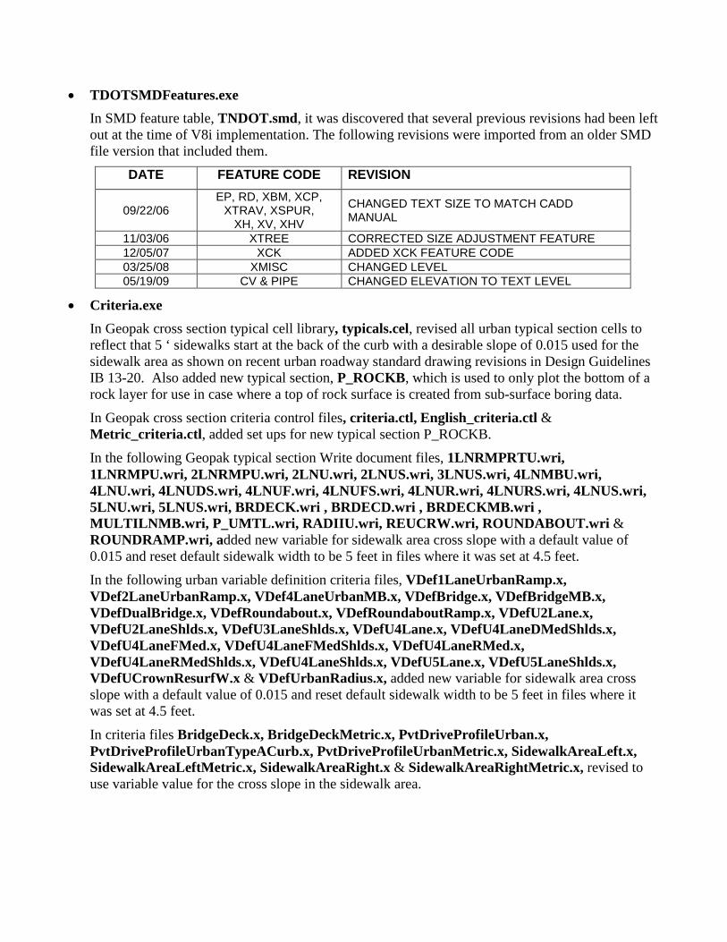
• TDOTSMDFeatures.exe In SMD feature table, TNDOT.smd, it was discovered that several previous revisions had been left out at the time of V8i implementation. The following revisions were imported from an older SMD file version that included them.
DATE FEATURE CODE REVISION
09/22/06 EP, RD, XBM, XCP,
XTRAV, XSPUR, XH, XV, XHV
CHANGED TEXT SIZE TO MATCH CADD MANUAL
11/03/06 XTREE CORRECTED SIZE ADJUSTMENT FEATURE 12/05/07 XCK ADDED XCK FEATURE CODE 03/25/08 XMISC CHANGED LEVEL 05/19/09 CV & PIPE CHANGED ELEVATION TO TEXT LEVEL
• Criteria.exe In Geopak cross section typical cell library, typicals.cel, revised all urban typical section cells to reflect that 5 ‘ sidewalks start at the back of the curb with a desirable slope of 0.015 used for the sidewalk area as shown on recent urban roadway standard drawing revisions in Design Guidelines IB 13-20. Also added new typical section, P_ROCKB, which is used to only plot the bottom of a rock layer for use in case where a top of rock surface is created from sub-surface boring data.
In Geopak cross section criteria control files, criteria.ctl, English_criteria.ctl & Metric_criteria.ctl, added set ups for new typical section P_ROCKB.
In the following Geopak typical section Write document files, 1LNRMPRTU.wri, 1LNRMPU.wri, 2LNRMPU.wri, 2LNU.wri, 2LNUS.wri, 3LNUS.wri, 4LNMBU.wri, 4LNU.wri, 4LNUDS.wri, 4LNUF.wri, 4LNUFS.wri, 4LNUR.wri, 4LNURS.wri, 4LNUS.wri, 5LNU.wri, 5LNUS.wri, BRDECK.wri , BRDECD.wri , BRDECKMB.wri , MULTILNMB.wri, P_UMTL.wri, RADIIU.wri, REUCRW.wri, ROUNDABOUT.wri & ROUNDRAMP.wri, added new variable for sidewalk area cross slope with a default value of 0.015 and reset default sidewalk width to be 5 feet in files where it was set at 4.5 feet.
In the following urban variable definition criteria files, VDef1LaneUrbanRamp.x, VDef2LaneUrbanRamp.x, VDef4LaneUrbanMB.x, VDefBridge.x, VDefBridgeMB.x, VDefDualBridge.x, VDefRoundabout.x, VDefRoundaboutRamp.x, VDefU2Lane.x, VDefU2LaneShlds.x, VDefU3LaneShlds.x, VDefU4Lane.x, VDefU4LaneDMedShlds.x, VDefU4LaneFMed.x, VDefU4LaneFMedShlds.x, VDefU4LaneRMed.x, VDefU4LaneRMedShlds.x, VDefU4LaneShlds.x, VDefU5Lane.x, VDefU5LaneShlds.x, VDefUCrownResurfW.x & VDefUrbanRadius.x, added new variable for sidewalk area cross slope with a default value of 0.015 and reset default sidewalk width to be 5 feet in files where it was set at 4.5 feet.
In criteria files BridgeDeck.x, BridgeDeckMetric.x, PvtDriveProfileUrban.x, PvtDriveProfileUrbanTypeACurb.x, PvtDriveProfileUrbanMetric.x, SidewalkAreaLeft.x, SidewalkAreaLeftMetric.x, SidewalkAreaRight.x & SidewalkAreaRightMetric.x, revised to use variable value for the cross slope in the sidewalk area.

In BridgeDeck.x & BridgeDeckMetric.x, made the following changes: Added program code to set variables to stop any current ditches or special ditches from being plotted in the plan view to prevent ditch lines from connecting across the bridge area to another ditch beyond the bridge. Revised single slope median barrier options to only include standard heights 32 in. and 51 in. Revised code that forms the chamfer at the top of single slope parapet and median barrier walls to more accurately draw that feature. Added new code to place 32 inch or 51 inch single slope barrier at edge of sidewalk on left or right. Added additional traps to prevent sidewalks from being placed on the inside area of dual bridge placements.
• 3PC.exe Updated programs PipeEndwall_Computation.x & PipeEndwall_ComputationMetric.x. Removed program coding to compile structural steel quantities and added traps using the endwall type with pipe diameter and side slope to set the appropriate safety endwall item number as well as the quantity of 1 since they are set up as an each unit item. Also reset concrete and reinforcing steel quantity values at 0 to handle safety endwalls placed previously with values entered for those items. Endwall type traps include functionality to handle endwall types with or without quote marks.
Office
• DDOCS.exe Added new Word letter template, NEPA Project Description Form.dotx, as described in Design Guidelines IB 13-21.
Revised Word template, Design Exception Request.dotx, to reflect changes shown in Design Guidelines IB 13-23.
• 2ndSheets.exe In Word template English Index & Std Dwgs.dotx, updated sheet index and standard drawing list with revision dates as presented in Design Guidelines IBs 13-18, 13-20, 13-22 & 13-25.
• EnglishTab.exe & MetricTab.exe Added new drainage Excel templates for tabulation of endwall quantities: Cross Drain Endwalls.xltx, Side Drain Endwalls.xltx and Median Drain Endwalls.xltx.
Excel template Storm Drainage Structure Tab Builder.xltm has been updated to use new item numbers for round junction box drainage structures and to count them as each rather than by depth as specified in the T.D.O.T. Drainage Manual revision dated September 13, 2013.
Renamed Excel template, Cross Drain Arterials WO Full Access Control.xltx, as Cross Drain Arterials.xltx to reflect its current designation in the T.D.O.T. Drainage Manual.
Our drainage Excel templates for cross drains, side drains & median drains: Cross Drain Freeways.xltx, Cross Drain Arterials.xltx, Cross Drain Collectors.xltx, Cross Drain Local Roads.xltx, Side Drain.xltx and Median Drains.xltx, have been updated to reflect changes as
specified in the T.D.O.T. Drainage Manual revision dated September 13, 2013. This concerned the elimination of endwall quantity tabulation within these pipe tabulations.
Aerial Survey
• ASdata.exe Revised color 64 which is used for urban features from the default gray to a more visible purple in Aerial Survey color table AerialColorTable.tbl.
• ASFeatureTable.exe In feature table Aerial50 Features Table.mdb, all features have been reviewed and updated for correct level and symbology as well as other control settings as noted below. Note that even though many features only use either the linear or point controls sometimes with the text feature control, all of these have been updated for correctness. Revisions are grouped by category as they appear in the feature table.
Levels have been set by name. The level number is provided for reference only. During the course of this update it has been determined that ISFC software does not truly honor level names. It will look for the level number from the level name that was set and will place it on that level, whatever the name may be. If it doesn’t find that level number it will create a new level with that number. Due to these facts, it is critical that all users create clean new DGN files using the current version of the seed file seedz.dgn when starting new files, never copy old ones, and do not create any new levels in the file which can change the numbering sequence.
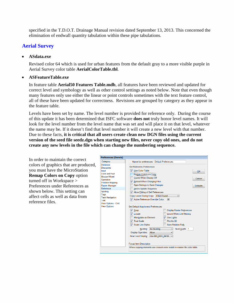
In order to maintain the correct colors of graphics that are produced, you must have the MicroStation Remap Colors on Copy option turned off in Workspace > Preferences under References as shown below. This setting can affect cells as well as data from reference files.
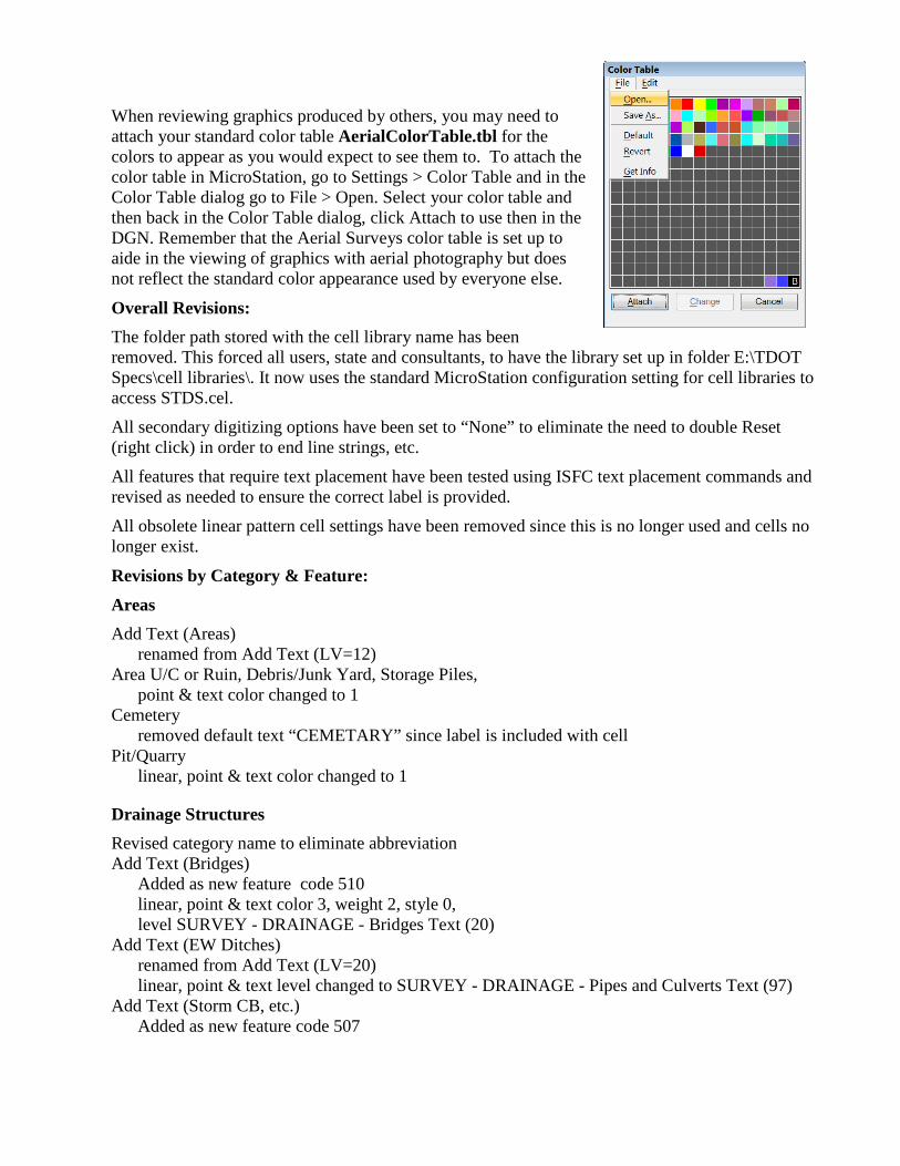
When reviewing graphics produced by others, you may need to attach your standard color table AerialColorTable.tbl for the colors to appear as you would expect to see them to. To attach the color table in MicroStation, go to Settings > Color Table and in the Color Table dialog go to File > Open. Select your color table and then back in the Color Table dialog, click Attach to use then in the DGN. Remember that the Aerial Surveys color table is set up to aide in the viewing of graphics with aerial photography but does not reflect the standard color appearance used by everyone else.
Overall Revisions: The folder path stored with the cell library name has been removed. This forced all users, state and consultants, to have the library set up in folder E:\TDOT Specs\cell libraries\. It now uses the standard MicroStation configuration setting for cell libraries to access STDS.cel.
All secondary digitizing options have been set to “None” to eliminate the need to double Reset (right click) in order to end line strings, etc.
All features that require text placement have been tested using ISFC text placement commands and revised as needed to ensure the correct label is provided.
All obsolete linear pattern cell settings have been removed since this is no longer used and cells no longer exist.
Revisions by Category & Feature: Areas Add Text (Areas) renamed from Add Text (LV=12) Area U/C or Ruin, Debris/Junk Yard, Storage Piles, point & text color changed to 1 Cemetery removed default text “CEMETARY” since label is included with cell Pit/Quarry linear, point & text color changed to 1
Drainage Structures Revised category name to eliminate abbreviation Add Text (Bridges) Added as new feature code 510 linear, point & text color 3, weight 2, style 0, level SURVEY - DRAINAGE - Bridges Text (20) Add Text (EW Ditches) renamed from Add Text (LV=20) linear, point & text level changed to SURVEY - DRAINAGE - Pipes and Culverts Text (97) Add Text (Storm CB, etc.) Added as new feature code 507
linear, point & text color 3, weight 2, style 0, level SURVEY - DRAINAGE - Storm Sewer Text (101) Box Culvert (Urban) deleted, feature code 507 Box Culvert renamed from Box Culvert (Rural) text level changed to SURVEY - DRAINAGE - Pipes and Culverts Text (97) Catchbasin text level changed to SURVEY - DRAINAGE - Storm Sewer Text (101) Dam/Spillway, Levee, Dock, Stream Gauge moved from category Non Transportation linear, point & text color changed to 3 linear & point level changed to SURVEY - DRAINAGE - Pipes and Culverts (93) text level changed to SURVEY - DRAINAGE - Pipes and Culverts Text (97) “Dock” renamed from Pier “Stream Gauge” renamed from Stream Gauge Endwall, Special Ditch (Paved) linear & point level changed to SURVEY - DRAINAGE - Pipes and Culverts (93) text level changed to SURVEY - DRAINAGE - Pipes and Culverts Text (97) Manhole moved to category Utilities – Ground Safety Grate deleted, feature code 510
isdc Obscured Area text color changed to 6 Water Spot Elevation linear & point level changed to SURVEY - CONTOURS - Index with Text (4)
Mapping Setup Add Text (Setup) renamed from Add Text (LV=3) text level changed to SURVEY - AERIAL SURVEY - Mapping Setup - with Text (331) Mapping Limits text level changed to SURVEY - AERIAL SURVEY - Mapping Setup - with Text (331) Set Map Scale deleted, feature code 901
Natural Drainage Add Text (Natural Drainage) renamed from Add Text (LV=17) text level changed to SURVEY - DRAINAGE - Natural Features Text (311) Stream, River, Pond, Lake, Creek, Spring, Swamp-Line, Swamp-cell, Rapids or Waterfalls, Irrigation Ditches text level changed to SURVEY - DRAINAGE - Natural Features Text (311)
NonTransportation Add Text (Non Trans.) renamed from Add Text (LV=12) Dam/Spillway, Levee, Stream Gauge moved to category Drainage Structures Flag Pole removed default text “FLAG” since label is included with cell LP Tank text level changed to SURVEY - NON-TRANSPORTATION - Features Text (12) Odd Shaped Building, Orthogonal Building text level changed to SURVEY - NON-TRANSPORTATION - Buildings Text (129) Pipelines, Radio/TV/Cell Tower moved to category Utilities – Ground Short Fence linear updated with new custom line style for short fence (FENCE SHORT) Sidewalks - Private renamed from Private Sidewalks Swimming Pools, Patio/Slab/Deck, Stairways, Chimney, Tank/Silo(Circular) linear & point level changed to SURVEY - NON-TRANSPORTATION - Buildings (125) text level changed to SURVEY - NON-TRANSPORTATION - Buildings Text (129) Stairways updated with new vba program to replace obsolete ucm program
Roadside Barriers Add Text (Roadside Barriers) renamed from Add Text (LV=8) linear, point & text level changed to SURVEY - ROADSIDE BARRIERS with Text (181) Impact Attenuator, Jersey Barrier, Median Div Guardrail, Single Guardrail, Tran. Retaining Wall text level changed to SURVEY - ROADSIDE BARRIERS with Text (181) Cable Barrier Added as new feature code 146 linear, point & text color 11, weight 2, style 8 (custom line style CABLE BARRIER), level SURVEY - ROADSIDE BARRIERS with Text (181)
Signs/Traffic Control Revised category name to eliminate abbreviation Add Text (Traffic) renamed from Add Text (LV=23)
Transportation Add Text (Other Trans.) Added as new feature code 137 linear, point & text color 11, weight 2, style 0 level SURVEY - TRANSPORTATION - Features Text (193) Add Text (Railroads) Added as new feature code 136
linear, point & text color 11, weight 2, style 0, level SURVEY - TRANSPORTATION - Railroads Text (198) Add Text (Roads) renamed from Add Text (LV=8) Add Text (Other Trans.) Added as new feature code 137 linear, point & text color 11, weight 2, style 0, level SURVEY - TRANSPORTATION - Features Text (193) Centerline of Road linear, point & text changed to breakline level and symbology; color 3, weight 2, style 0, level SURVEY - DTM - Breaklines (29) Curb, Curb w/Gutter, Curb Ramp, Sidewalk-Public point color changed to 64 text color changed to 11 linear & point level changed to SURVEY - TRANSPORTATION - Features (189) text level changed to SURVEY - TRANSPORTATION - Features Text (193) “Curb Ramp” renamed from Handicap Ramp removed default text “SIDEWALK” from Sidewalk-Public since no label is required Paved Driveway, Unpaved Driveway, Paved Parking Lot, Unpaved Parking Lot text color changed to 11 linear & point level changed to SURVEY - TRANSPORTATION - Features (189) text level changed to SURVEY - TRANSPORTATION - Features Text (193) removed default text “PARKIING” since no label is required Bike Paths, Paved Shoulder, Runways/Helipad, Tunnel Entrance text color changed to 11 linear & point level changed to SURVEY - TRANSPORTATION - Features (189) text level changed to SURVEY - TRANSPORTATION - Features Text (193) Railroad Centerline, RR Switch text color changed to 11 text level changed to SURVEY - TRANSPORTATION - Railroads Text (198) Trails linear style changed to 2 text color changed to 11 linear & point level changed to SURVEY - TRANSPORTATION - Features (189) text level changed to SURVEY - TRANSPORTATION - Features Text (193)
Utilities - Ground Add Text(Misc) renamed from Add Text(LV=25) linear, point & text color changed to 2 linear, point & text level changed to SURVEY - UTILITIES - Poles and Miscellaneous with Text (236) Cable TV Box linear & point level changed to SURVEY - UTILITIES - Cable (Underground) with Text (25) Fire Hydrant, Water Meter, Water Valve text level changed to SURVEY - UTILITIES - Water with Text (252)
Lighting Ctrl Center linear, point & text color changed to 2 text level changed to SURVEY - UTILITIES - Electric (Lighting) with Text (208) Natural Gas Meter, Natural Gas Valve text level changed to SURVEY - UTILITIES - Gas with Text (224) Manhole moved from category Drainage Structures text color changed to 2 linear, point & text level changed to SURVEY - UTILITIES - Poles and Miscellaneous with Text (236) Pipelines, Radio/TV/Cell Tower moved from category Non-Transportation linear, point & text color changed to 2 linear, point & text level changed to SURVEY - UTILITIES - Poles and Miscellaneous with Text (236) “Radio/TV/Cell Tower” renamed from Radio/TV Tower Pull Box linear, point & text color changed to 7 linear, point & text level changed to SURVEY - TRAFFIC CONTROL - Signs and Devices with Text (23) Tele. Booth, Tele. Box moved to category Utilities - Overhead Tele. Pedestal text level changed to SURVEY - UTILITIES - Telephone (Underground) with Text (248) Utility Box linear, point & text color changed to 2 linear, point & text level changed to SURVEY - UTILITIES - Poles and Miscellaneous with Text (236)
Utilities - Overhead Revised category name to eliminate abbreviation Add Text (LV=25) deleted, feature code 115 Power Substation linear updated with new custom line style for short fence (FENCE SHORT) turned off obsolete pattern option linear, point & text color changed to 5 text level changed to SURVEY - UTILITIES - Electric (Overhead) with Text (212) Tele. Booth, Tele. Box moved from category Utilities - Ground linear, point & text level changed to SURVEY - UTILITIES - Telephone (Overhead) with Text (244) Trans. Tower text level changed to SURVEY - UTILITIES - Electric (Overhead) with Text (212) Utility Pole (All) text level changed to SURVEY - UTILITIES - Poles and Miscellaneous with Text (236)
Vegetation Add Text (Vegetation) renamed from Add Text (LV=18)
Iplot
No changes.
AutoTrack
No changes.
Documentation
• CADDV8.pdf See the Manual Revisions at the end of document for detailed description of changes which reflect this CADD update as well as other informational changes.
• TDOT Roadway Design Division Programs.pdf Added the following new program workflows:
Aerial Survey Tools pages 4-10 Fix Pre-V8i Dot Patterns page 27 Place Plan Phase Stamps in Files pages 284-290
Updated the following program workflows with new images and some description changes: Introduction page 1 Draw Curb Ramp pages 118,127-135 Traffic Flow Diagrams page 145 Draw Prop. Type "A" Pipe Endwall in Plan page 163 Draw Prop. Type "U" Pipe Endwall in Plan page 166 Draw Prop. Type "SEW" Pipe Endwall in Plan page 169 Draw Prop. Type Straight Pipe Endwall in Plan page 172 Plan Phase Stamps page 283 Pipe Endwall Computation page 374
• 2ndSheetsV8.pdf Added new endwall tabulation templates, Cross Drain Endwalls.xltx, Side Drain Endwalls.xltx and Median Drain Endwalls.xltx, to template list on page 17. Also renamed Excel template, Cross Drain Arterials WO Full Access Control.xltx, as Cross Drain Arterials.xltx to reflect its current designation in the T.D.O.T. Drainage Manual.
• TDOT SURVEY SMD V8i FEATURE CODES.pdf Added revision note to revision list page at end referring to import of revised features (09/22/06 to 05/19/09) from older SMD file version since they had been unintentionally left out with Geopak V8i implementation.
• Adding Plan Phase Stamps as a Watermark in PDF Plan Sets.pdf Added paragraph at beginning on page 1 concerning the use of the Place Plan Phase Stamps in Files tool instead of this workflow.
• TDOT Roadway Design Division V8 Configurations for Consultant CADD Managers.pdf Revised locations for hard coded file paths in Excel templates Guardrail Tab Builder.xltm, Storm Drainage Pipe Tab Builder.xltm & Storm Drainage Structure Tab Builder.xltm to reflect recent changes.
• TitleSheets.pdf Step by step instructions have been updated to reflect functionality in MicroStation V8i and to reflect the change from CIT to TIF images for some county map files.
• LocationMaps.pdf Step by step instructions have been updated to reflect functionality in MicroStation V8i and to reflect the change from CIT to TIF images for some county map files.
Tennessee Map Files for MicroStation
• *.exe In all map DGN files, ran the new tool to fix pre-V8i dot patterns to ensure that dot patterning used to denote city or other political boundaries as well as water surface features appear correctly when plotted from MicroStation or PDF documents. Replaced all CIT image files which are currently failing to print from MicroStation’s Print Organizer function with TIF image files that are honored by that function.
• County Map Index.pdf Updated to reflect the change from CIT to TIF images for some map files available from web page, Tennessee Map Files for MicroStation.

August 2013 Update This update contains several fixes and corrections as well as some new enhancements. The T.D.O.T. Roadway Design Division’s Roadway Design Guidelines, Drainage Manual and Standard Roadway Drawings have been updated and this CADD standard update includes many changes to templates, programs, etc. which reflect changes in those documents. Some highlights include the following items.
We now have various crash cushion devices available including plastic drums with sand at different weights as well as several types of guardrail attenuators. The sand barrels are set up as cells and are available through the Traffic Control Cells dialog. The guardrail attenuators are set up as line styles so that the length can be set as needed. Use Geopak’s D&C Manager to access those under Guardrail> Attenuators.
Several other new line styles have been added as well. Existing and proposed cable barrier as used for cross-over protection in the medians on the interstate are now available. We also have a new 12” pavement marking line with a 10’ dash & 10’ gap for use along HOV lanes on the interstate. For use along the center of 2 lane roadways, a 4” centerline rumble stripe is now available for application.
Our drainage library now includes the new round junction box structures based on the round type 12 catch basins. These new drainage node items have been unofficially designated as type 6 junction boxes in the drainage library to differentiate them from the other junction box structures which are types 1 through 5.
Our Draw Curb Ramp program and urban cross section criteria files have been updated to reflect the various dimension changes that are now specified on the latest curb ramp standard roadway drawings.
The documentation file, TDOT Roadway Design Division Programs.pdf, has been completely reviewed and updated for application in V8i on Windows 7.
We have added the new documentation file Introduction to V8i on Windows 7.pdf. This is the course guide for the V8i seminar series of the same name presented by the Roadway Design Division in April, May & June of 2013.
For any still running V8 2004 software: Note that most download files are compatible with V8 2004 software. Some exceptions include the interface file and some programs that include software based file paths. The default download locations are set up for V8i but you can adjust those locations on the fly. Use the following default base paths for V8 2004 … MicroStation C:\Program Files\Bentley\Workspace\system Geopak C:\Program Files\GeopakStandards Office C:\Program Files\Microsoft Office\Templates Iplot C:\Program Files\Common Files\InterPlot\iplot InterPlot C:\Program Files\InterPlot Client
Review the specific file revision descriptions below for further details on these changes and others.
MicroStation
• EngCell.exe & MetCell.exe In STDS.cel & METRIC.cel: Added the following new sand barrel crash cushion cells:
CCBARREL200 200 lb. plastic drum w/sand crash cushion CCBARREL400 400 lb. plastic drum w/sand crash cushion CCBARREL700 700 lb. plastic drum w/sand crash cushion CCBARREL1400 1400 lb. plastic drum w/sand crash cushion CCBARREL2100 2100 lb. plastic drum w/sand crash cushion
Added the following new traffic low diagram cells for semi-direct “T” interchanges
TMINTSDTL Semi-direct “T” Interchange left side only TMINTSDTR Semi-direct “T” Interchange right side only
Added new temporary traffic control cell, TVPLT, which is a single face vertical panel sign set up for use on the left side of the roadway. This was set up to avoid upside down text since this cell includes the text label “V”.
Added new proposed cable barrier terminal cell, CBT, which is to be used with the new proposed cable barrier custom line style.
In STDS.cel only:
Added the following new Geopak drainage node cells:
JB4DIA Junction Box 4’ Diameter JB5DIA Junction Box 5’ Diameter JB6DIA Junction Box 6’ Diameter JB7DIA Junction Box 7’ Diameter JB8DIA Junction Box 8’ Diameter JB9DIA Junction Box 9’ Diameter JB10DIA Junction Box 10’ Diameter
In SIGN.cel: Added the following new solar flashing warning beacon cells:
LTSFAA Amber solar flashing assembly LTSFAR Red solar flashing assembly
Added the following new construction sign cells:
M4.8 Detour W5.1 Road Narrows (Words)
• Seed.exe In DGN seed files EnglishGeneralNotes.dgn & EnglishEPSCSpecialNotes.dgn, updated all references to the “Design Division” to specify “Roadway Design Division” as specified in Design Guidelines IB 13-09.
In DGN seed file Ind&StdDwgsEng.dgn, updated standard drawing list and revision dates as presented in Design Guidelines IB 13-13.
• Symb.exe Added the following new line styles:
CABLE BARRIER Existing Cable Barrier CABLE BARRIER PROP Proposed Cable Barrier GUARDRAIL ATTENUATOR SACRIFICIAL
Guardrail attenuator crash cushion - sacrificial
GUARDRAIL ATTENUATOR NARROW REUSABLE
Guardrail attenuator crash cushion – narrow reusable
GUARDRAIL ATTENUATOR WIDE REUSABLE
Guardrail attenuator crash cushion – wide reusable
GUARDRAIL ATTENUATOR NARROW LOW MAINTENANCE
Guardrail attenuator crash cushion – narrow low maintenance
GUARDRAIL ATTENUATOR WIDE LOW MAINTENANCE
Guardrail attenuator crash cushion – wide low maintenance
PVMT MRK 10-10 W 12" Pavement marking stripe style for white 12” wide stripe with 10’ dash and 10’ gaps for use along HOV lanes
PVMT MRK 10-30 Y 4" Pavement marking stripe style for yellow 4” wide stripe with 10’ dash and 30’ gaps for use along the center of 2 lane roadways
PVMT MRK 10-30 Y 6" Pavement marking stripe style for yellow 4” wide stripe with 10’ dash and 30’ gaps for use along the center of 2 lane roadways
RUMBLE STRIPE 4" CENTER CONT
Centerline 4” rumble stripe for use along the center of 2 lane roadways
• TDOTinterface.exe In the Roadway Design Division Tool Strip, added access to the Survey Project Workflow Toolbox under the Roadway Design Division Toolbox icon with the ability to open them in a separate tool strip.
In the TDOT drop down menu: Updated all references to the “Design Division” to specify “Roadway Design Division”. Updated all references to “Handicap Ramp” to specify “Curb Ramp”. Removed call for obsolete tool Drainage (Plan)> Draw Type L Endwall.

• VBA.exe Revised the following individual programs: CellTools.mvba In function “Place Cells Along an Element”, added an option on the
dialog to place a cell at the end when the distance at the end is less than the specified spacing. Added code in subroutine PLaceAlong to trap that situation and to place the cell if the option is on. Also added code to add all cells placed into a separate graphic group. Added code to the subroutine UserForm_Terminate to reset scale and graphic group values just in case these resets get skipped in main code. Revised trap for while loop that does main cell placements to deal with situations where total distance and cumulative distance difference is near zero in value which caused it to skip final cell placement that should have been done by default.
ConstructionSignCells.mvba Added signs Road Narrows (W5-1) and Detour (M4-8). Also added code to turn the active fill off for program modules which place proposed sign numbers in an ellipse.
DrainagePlanCells.mvba Removed command button and associated code used to access the Draw Proposed "L" Endwall tool since those endwalls are no longer used.
DrawBoxPlan.mvba Added traps and fixes for text label placed at angle of culvert or bridge to prevent placement of upside down text. This occurred at times when left and right ends of structure were reversed or on side roads that ended up with their left & rights being adverse to normal left & right. Also corrected the tab order in the dialog so that users can tab from field to field as they enter control data.
DrawBoxProfile.mvba Corrected the tab order in the dialog so that users can tab from field to field as they enter control data.
DrawCurbRamp.mvba Changed default perpendicular ramp slope length to be 6' as shown on standard roadway drawing RP-H-4 and minimum width for parallel ramps to be 4' as shown on standard roadway drawing RP-H-5. Revised all references to “handicap ramps” to be “curb ramps”.
DrawPipeProfile.mvba Added code to place proposed storm drainage code cell on correct level.
DrawSlabProfile.mvba Corrected the tab order in the dialog so that users can tab from field to field as they enter control data.
DrawTypeSTEndwall.mvba Revised quantities and adjustments applied for those values when multiple and/or skewed pipes are involved as indicated on revised standard roadway drawing D-PE-4.
DrawTypeUEndwall.mvba Removed coding and dialog controls for type U endwalls as previously shown on standard roadway drawing D-PE-4 which included number of pipes and side slope options 2:1, 1.5:1. Revised drawings listed at top of dialog to show that it no longer supports endwalls from drawing D-PE-4.
HA_IntersectLabel.mvba Removed use of subroutine to build station values when less than 100 since Geopak handles that correctly now.
HApoints.mvba Corrected code to handle chains that begin with a curve without a spiral or chains that consist of only a single curve without a spiral.
HighwayRouteSignCells.mvba Added code to turn the active fill off for program modules which place proposed sign numbers in an ellipse.
LabelConduit.mvba Moved code to reset text style to occur immediately after label graphics are placed. It was under the command events subroutine which caused MicroStation to freeze up if any text command was chosen.
LabelPullBox.mvba Moved code to reset text style to occur immediately after label graphics are placed. It was under the command events subroutine which caused MicroStation to freeze up if any text command was chosen.
RegulatorySignCells.mvba Added access to red and amber solar flashing assembly light cells as shown on standard roadway drawing T-S-24. Also added code to turn the active fill off for program modules which place proposed sign numbers in an ellipse.
SchoolSignCells.mvba Added code to turn the active fill off for program modules which place proposed sign numbers in an ellipse.
SignalizationDeviceCells.mvba Revised all references to “handicap ramps” to be “curb ramps”.
StaOffLabel.mvba Removed use of subroutine to build station values when less than 100 since Geopak handles that correctly now.
TennesseeSignCells.mvba Added code to turn the active fill off for program modules which place proposed sign numbers in an ellipse.
TextstylesPlus.mvba Added code to start default command after current style reset so that the Place Text command is not left active from the reset sequence.
TDOTDesignDivToolbox.mvba Revised title at top of dialog to reflect use by the Roadway Design Division.
TrafficControlCells.mvba Added access to new single face vertical panel cell for use on the left side of roadways and to crash cushion barrel cells based on pounds of sand they contain.
TrafficFlowDiagramCells.mvba Added new traffic flow diagrams for semi-direct "T" interchanges with semi-direct ramp connections on left or right.
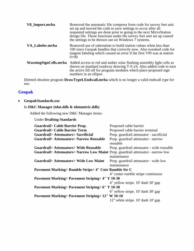
V8_Import.mvba Removed the automatic file compress from code for survey feet unit set up and moved the code to save settings to occur after all requested settings are done prior to going to the next MicroStation design file. Those functions under the survey feet unit set up caused the settings to be thrown out on Windows 7 systems.
VA_Labeler.mvba Removed use of subroutine to build station values when less than 100 since Geopak handles that correctly now. Also tweaked code for tangent labeling which caused an error if the first VPI was at station 0+00.
WarningSignCells.mvba Added access to red and amber solar flashing assembly light cells as shown on standard roadway drawing T-S-24. Also added code to turn the active fill off for program modules which place proposed sign numbers in an ellipse.
Deleted obsolete program DrawTypeLEndwall.mvba which is no longer a valid endwall type for use.
Geopak
• GeopakStandards.exe In D&C Manager (tdot.ddb & tdotmetric.ddb)
Added the following new D&C Manager items:
Under Drafting Standards
Guardrail> Cable Barrier Prop. Proposed cable barrier Guardrail> Cable Barrier Term Proposed cable barrier terminal Guardrail> Attenuators> Sacrificial Prop. guardrail attenuator - sacrificial Guardrail> Attenuators> Narrow Reusable Prop. guardrail attenuator - narrow
reusable Guardrail> Attenuators> Wide Reusable Prop. guardrail attenuator - wide reusable Guardrail> Attenuators> Narrow Low Maint Prop. guardrail attenuator - narrow low
maintenance Guardrail> Attenuators> Wide Low Maint Prop. guardrail attenuator - wide low
maintenance Pavement Marking> Rumble Strips> 4" Cntr Rumble Str C
4" center rumble stripe continuous Pavement Marking> Pavement Striping> 4" Y 10-30
4" yellow stripe. 10' dash 30' gap Pavement Marking> Pavement Striping> 6" Y 10-30
6" yellow stripe. 10' dash 30' gap Pavement Marking> Pavement Striping> 12" W 10-10
12" white stripe. 10' dash 10' gap
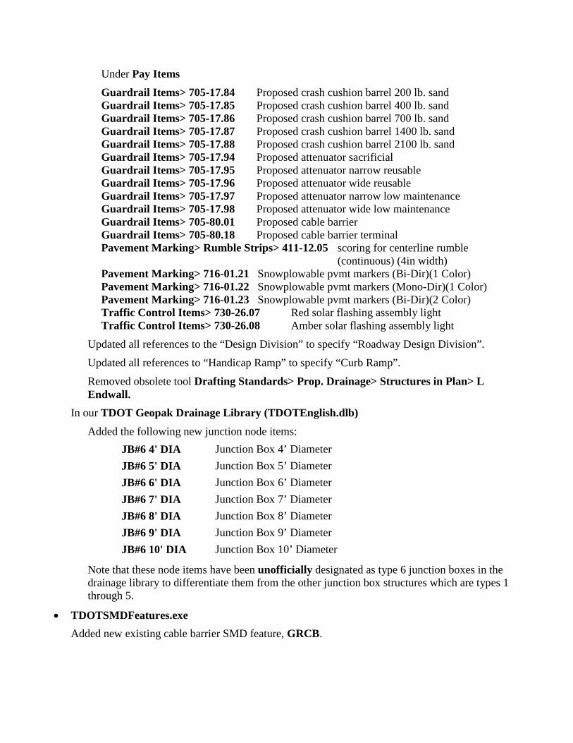
Under Pay Items
Guardrail Items> 705-17.84 Proposed crash cushion barrel 200 lb. sand Guardrail Items> 705-17.85 Proposed crash cushion barrel 400 lb. sand Guardrail Items> 705-17.86 Proposed crash cushion barrel 700 lb. sand Guardrail Items> 705-17.87 Proposed crash cushion barrel 1400 lb. sand Guardrail Items> 705-17.88 Proposed crash cushion barrel 2100 lb. sand Guardrail Items> 705-17.94 Proposed attenuator sacrificial Guardrail Items> 705-17.95 Proposed attenuator narrow reusable Guardrail Items> 705-17.96 Proposed attenuator wide reusable Guardrail Items> 705-17.97 Proposed attenuator narrow low maintenance Guardrail Items> 705-17.98 Proposed attenuator wide low maintenance Guardrail Items> 705-80.01 Proposed cable barrier Guardrail Items> 705-80.18 Proposed cable barrier terminal Pavement Marking> Rumble Strips> 411-12.05 scoring for centerline rumble
(continuous) (4in width) Pavement Marking> 716-01.21 Snowplowable pvmt markers (Bi-Dir)(1 Color) Pavement Marking> 716-01.22 Snowplowable pvmt markers (Mono-Dir)(1 Color) Pavement Marking> 716-01.23 Snowplowable pvmt markers (Bi-Dir)(2 Color) Traffic Control Items> 730-26.07 Red solar flashing assembly light Traffic Control Items> 730-26.08 Amber solar flashing assembly light
Updated all references to the “Design Division” to specify “Roadway Design Division”.
Updated all references to “Handicap Ramp” to specify “Curb Ramp”.
Removed obsolete tool Drafting Standards> Prop. Drainage> Structures in Plan> L Endwall.
In our TDOT Geopak Drainage Library (TDOTEnglish.dlb) Added the following new junction node items:
JB#6 4' DIA Junction Box 4’ Diameter JB#6 5' DIA Junction Box 5’ Diameter JB#6 6' DIA Junction Box 6’ Diameter JB#6 7' DIA Junction Box 7’ Diameter JB#6 8' DIA Junction Box 8’ Diameter JB#6 9' DIA Junction Box 9’ Diameter JB#6 10' DIA Junction Box 10’ Diameter
Note that these node items have been unofficially designated as type 6 junction boxes in the drainage library to differentiate them from the other junction box structures which are types 1 through 5.
• TDOTSMDFeatures.exe Added new existing cable barrier SMD feature, GRCB.
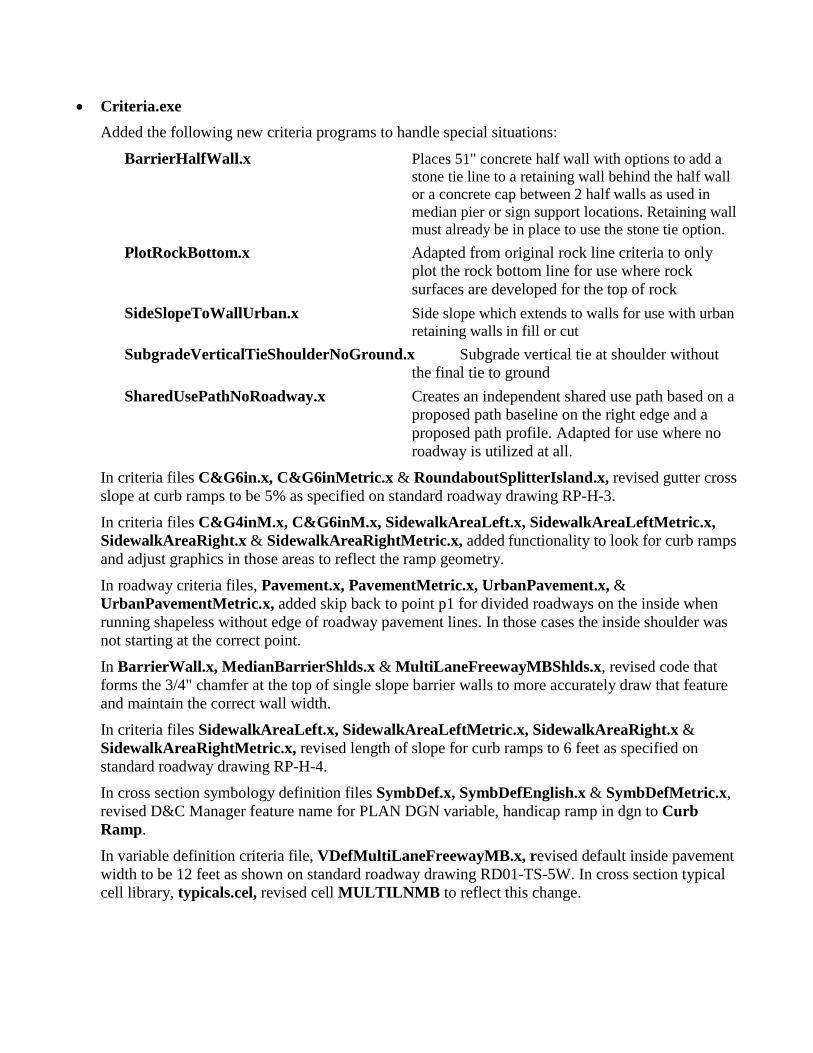
• Criteria.exe Added the following new criteria programs to handle special situations:
BarrierHalfWall.x Places 51" concrete half wall with options to add a stone tie line to a retaining wall behind the half wall or a concrete cap between 2 half walls as used in median pier or sign support locations. Retaining wall must already be in place to use the stone tie option.
PlotRockBottom.x Adapted from original rock line criteria to only plot the rock bottom line for use where rock surfaces are developed for the top of rock
SideSlopeToWallUrban.x Side slope which extends to walls for use with urban retaining walls in fill or cut
SubgradeVerticalTieShoulderNoGround.x Subgrade vertical tie at shoulder without the final tie to ground
SharedUsePathNoRoadway.x Creates an independent shared use path based on a proposed path baseline on the right edge and a proposed path profile. Adapted for use where no roadway is utilized at all.
In criteria files C&G6in.x, C&G6inMetric.x & RoundaboutSplitterIsland.x, revised gutter cross slope at curb ramps to be 5% as specified on standard roadway drawing RP-H-3.
In criteria files C&G4inM.x, C&G6inM.x, SidewalkAreaLeft.x, SidewalkAreaLeftMetric.x, SidewalkAreaRight.x & SidewalkAreaRightMetric.x, added functionality to look for curb ramps and adjust graphics in those areas to reflect the ramp geometry. In roadway criteria files, Pavement.x, PavementMetric.x, UrbanPavement.x, & UrbanPavementMetric.x, added skip back to point p1 for divided roadways on the inside when running shapeless without edge of roadway pavement lines. In those cases the inside shoulder was not starting at the correct point.
In BarrierWall.x, MedianBarrierShlds.x & MultiLaneFreewayMBShlds.x, revised code that forms the 3/4" chamfer at the top of single slope barrier walls to more accurately draw that feature and maintain the correct wall width.
In criteria files SidewalkAreaLeft.x, SidewalkAreaLeftMetric.x, SidewalkAreaRight.x & SidewalkAreaRightMetric.x, revised length of slope for curb ramps to 6 feet as specified on standard roadway drawing RP-H-4.
In cross section symbology definition files SymbDef.x, SymbDefEnglish.x & SymbDefMetric.x, revised D&C Manager feature name for PLAN DGN variable, handicap ramp in dgn to Curb Ramp.
In variable definition criteria file, VDefMultiLaneFreewayMB.x, revised default inside pavement width to be 12 feet as shown on standard roadway drawing RD01-TS-5W. In cross section typical cell library, typicals.cel, revised cell MULTILNMB to reflect this change.
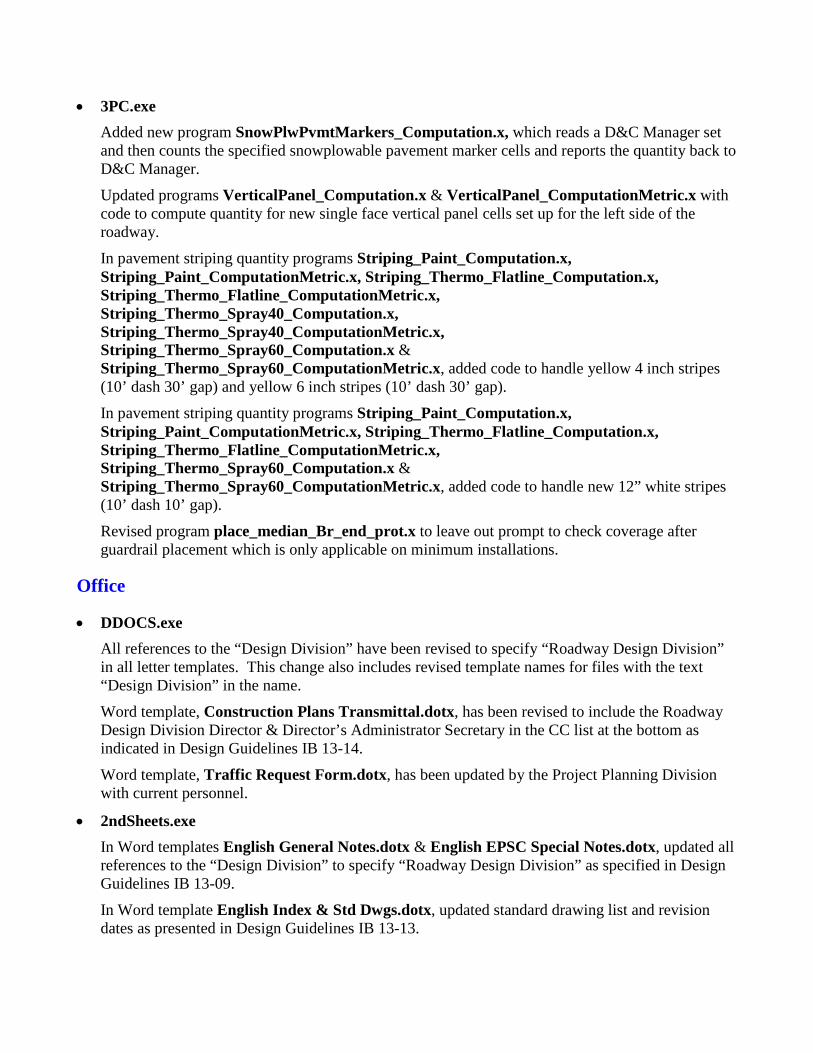
• 3PC.exe Added new program SnowPlwPvmtMarkers_Computation.x, which reads a D&C Manager set and then counts the specified snowplowable pavement marker cells and reports the quantity back to D&C Manager.
Updated programs VerticalPanel_Computation.x & VerticalPanel_ComputationMetric.x with code to compute quantity for new single face vertical panel cells set up for the left side of the roadway.
In pavement striping quantity programs Striping_Paint_Computation.x, Striping_Paint_ComputationMetric.x, Striping_Thermo_Flatline_Computation.x, Striping_Thermo_Flatline_ComputationMetric.x, Striping_Thermo_Spray40_Computation.x, Striping_Thermo_Spray40_ComputationMetric.x, Striping_Thermo_Spray60_Computation.x & Striping_Thermo_Spray60_ComputationMetric.x, added code to handle yellow 4 inch stripes (10’ dash 30’ gap) and yellow 6 inch stripes (10’ dash 30’ gap).
In pavement striping quantity programs Striping_Paint_Computation.x, Striping_Paint_ComputationMetric.x, Striping_Thermo_Flatline_Computation.x, Striping_Thermo_Flatline_ComputationMetric.x, Striping_Thermo_Spray60_Computation.x & Striping_Thermo_Spray60_ComputationMetric.x, added code to handle new 12” white stripes (10’ dash 10’ gap).
Revised program place_median_Br_end_prot.x to leave out prompt to check coverage after guardrail placement which is only applicable on minimum installations.
Office
• DDOCS.exe All references to the “Design Division” have been revised to specify “Roadway Design Division” in all letter templates. This change also includes revised template names for files with the text “Design Division” in the name.
Word template, Construction Plans Transmittal.dotx, has been revised to include the Roadway Design Division Director & Director’s Administrator Secretary in the CC list at the bottom as indicated in Design Guidelines IB 13-14.
Word template, Traffic Request Form.dotx, has been updated by the Project Planning Division with current personnel.
• 2ndSheets.exe In Word templates English General Notes.dotx & English EPSC Special Notes.dotx, updated all references to the “Design Division” to specify “Roadway Design Division” as specified in Design Guidelines IB 13-09.
In Word template English Index & Std Dwgs.dotx, updated standard drawing list and revision dates as presented in Design Guidelines IB 13-13.
• EnglishTab.exe & MetricTab.exe In drainage Excel template, Cross Drain Arterials WO Full Access Control.xltx, removed the SRTRP pipe type alternate as per update of the T.D.O.T. Drainage Manual.
In Excel templates Guardrail Tab Builder.xltmn Storm Drainage Structure Tab Builder.xltm & Storm Drainage Pipe Tab Builder.xltm , set up a folder path variable for the items.dat path and revised code to use variables.
Excel template Storm Drainage Structure Tab Builder.xltm has been updated to handle the new round junction box drainage structures when building tabulations. These are shown on standard roadway drawing D0-CB-99RB and are currently tabulated as round type 12 catch basins on which they are based.
Aerial Survey
No changes.
Iplot
No changes.
AutoTrack
No changes.
Documentation
• CADDV8.pdf Updated all references to the “Design Division” to specify “Roadway Design Division”.
Updated all references to “Handicap Ramp” to specify “Curb Ramp”.
See the Manual Revisions at the end of document for detailed description of changes which reflect this CADD update as well as other informational changes.
• TDOT Roadway Design Division Programs.pdf This document has been completely reviewed and updated for application in MicroStation & Geopak V8i on Windows 7 with new images and text revisions. The following revision notes reflect actual changes in work flow and additional information that has been added but does not include all of the general changes that have been done.
Updated all references to the “Design Division” to specify “Roadway Design Division”.
Updated all references to “Handicap Ramp” to specify “Curb Ramp”.
All cell placement programs have been updated to reflect the new cell placement control options and include the workflow for the placement type that is set by default. The Traffic Control Device Cells program has been expanded to also include a section on the Place Along cell placement option on pages 321-322.
Added the following new program workflows:
Generate 2D DGN from 3D Model's Top View page 16 Slotted Drain Computation page 358 Pipe Endwall Computation page 359 Snowplowable Pavement Markers Computation page 369
Updated the following program workflows: DGN Batch Text Editor pages 8-9 Move Raster by Datum Adjustment Factor pages 11-12 Set Iplot Default Settings page 17 Draw Exist. Pipe(s) on Profile by Center Flow Point pages 70-72 Draw Exist. Box Culvert or Bridge on Profile by Flow Point pages 73-75 Draw Exist. Slab Culvert or Bridge on Profile by Flow Point pages 76-78 Draw Curb Ramp pages 110-127 Draw Prop. Box Culvert or Bridge in Plan by 2 Points pages 149-152 Draw Prop. Type "A" Pipe Endwall in Plan pages 153-155 Draw Prop. Type "U" Pipe Endwall in Plan pages 156-158 Draw Prop. Type "SEW" Pipe Endwall in Plan pages 159-161 Draw Prop. Type Straight Pipe Endwall in Plan pages 162-164 Draw Permanent Slope Drain pages 165-168 Draw Prop. Pipe(s) on Profile by Center Flow Point pages 169-171 Draw Prop. Box Culvert or Bridge on Profile by Flow Point pages 172-174 Draw Prop. Slab Culvert or Bridge on Profile by Flow Point pages 175-177 Drainage Plan Cells page 183 Drainage Profile & Culvert Section Cells page 184 Draw Vehicle Trajectory Path pages 193-196 Draw Temporary Slope Drain page 228 Label EPSC Storm Water Outfalls pages 231-233 Place Proposed Trees page 246 Construction Sign Cells pages 302-305 Highway Route Sign Cells pages 307-311 Traffic Control Device Cells pages 320-322
Deleted the following obsolete program workflows:
Change Custom Linestyle Scale Draw Prop. Type "L" Pipe Endwall in Plan
• MicroStation V8 Manual.pdf Updated class files in tdotmicrostationclassfiles.exe with the following settings:
Defined Coordinate System EPSG:2274 NAD83 / Tennessee (ftUS) Custom Line Style Scale 50 or 10 (cross sections) Current Levels, Level Filters, Text Styles & Color Table Area Fill On in View 1
• TDOT GEOPAK Road Course Guide.pdf Updated class files in TDOTGeopakRoadClassFiles.exe with the following settings:
Defined Coordinate System EPSG:2274 NAD83 / Tennessee (ftUS) Custom Line Style Scale 50 or 10 (cross sections) Current Levels, Level Filters, Text Styles & Color Table Area Fill On in View 1
Corrected default folder for DTM display preference files in Exercise 3 on page 3-3.
• TDOT Geopak Survey Training Manual.pdf Updated class files in TDOT Geopak Survey Class Files.exe with the following settings:
Defined Coordinate System EPSG:2274 NAD83 / Tennessee (ftUS) Custom Line Style Scale 50 Current Levels, Level Filters, Text Styles & Color Table Area Fill On in View 1
• Introduction to V8i on Windows 7.pdf Added this new documentation file which is the course guide for the V8i seminar series of the same name presented by the Roadway Design Division in April, May & June of 2013.
• 2ndSheetsV8.pdf Updated web page image capture on page 25 to reflect standard folder path on Windows 7.
• TDOT SURVEY SMD V8 FEATURE CODES.pdf Added new existing cable barrier SMD feature, GRCB.
• TDOT Geopak Drainage Nodes.pdf Added the following new Geopak Drainage node items with their design control data on pages 5 & 11:
JB#6 4' DIA Junction Box 4’ Diameter JB#6 5' DIA Junction Box 5’ Diameter JB#6 6' DIA Junction Box 6’ Diameter JB#6 7' DIA Junction Box 7’ Diameter JB#6 8' DIA Junction Box 8’ Diameter JB#6 9' DIA Junction Box 9’ Diameter JB#6 10' DIA Junction Box 10’ Diameter

Note that these node items have been unofficially designated as type 6 junction boxes in the drainage library to differentiate them from the other junction box structures which are types 1 through 5. The control data for these structures from standard roadway drawing D0-CB-99RB is based on round type 12 catch basins as per the standard drawing.

March 2013 V8i Update All compatible files have been updated for use with MicroStation V8i (SELECT Series 2) version 08.11.07.443, Geopak V8i (SELECT Series 2) version 08.11.07.615, Office 2010 and Projectwise Interplot Organizer V8i version 08.11.07.420 on the Windows 7 operating system.
As needed new standard files have been developed to accommodate our current CADD requirements. New MicroStation visual basic applications have been developed to replace older obsolete MicroStation Basic and MDL programs. Most of these include enhancements from the previous tools.
CADD web pages have been updated to access V8i standard CADD files for placement on Windows 7 systems. On those systems, you must be an administrator to update config files which still reside in the software folders. All other downloads now go outside those folders, most to sub-folders under C:\Users\Public.
We now have a new template library for use with the Geopak V8i Roadway Designer tool in Corridor Modeling. We do not plan to replace our current set ups using criteria files for final design at this time but have set up the template library for use in developing display models of proposed designs for presentations at public hearings or other meetings. The template library has all of our primary roadway types as well as bridges, walls or other associated features. Our MicroStation standards include new levels for model displays which already have material assignments so that when models are produced they will be automatically rendered as pavement, concrete, grass, etc.
Every effort has been made to document all significant changes in the following sections. Due to the sheer volume of this update many small changes may not be specifically listed. This listing also represents maintenance updates done to our CADD standards since the last fully documented update in May 2011.
Review the specific file revision descriptions below for further details on these changes and others.
MicroStation
• EngCell.exe & MetCell.exe In STDS.cel & METRIC.cel: Reviewed all cells with minor edits as needed.
Removed obsolete T.D.O.T. Design Division File Room stamp from the upper left corner of sheet cells BDR2ND, BDRSHT, BDRSG, BDR7DC, GRDSHT, MGRID, PROSHT, SS1, SS2, SSHEET, TITLE & XSTSHT. Also deleted the separate cell for the file room stamp, FILERM.
Moved the engineer’s seal box to the left of the title block at the lower right corner on culvert cross sect sheet cell GRDSHT to remain clear of elevation annotation or other elements of the first culvert section that would appear on the sheet.
Corrected text size used for drainage profile cells DRPRO & DRPROPIPE to be 0.12”.
Rebuilt fill shapes in Erosion Prevention Sediment Control cells TCC, TCE, TCF and their legend cells TCCL, TCEL, TCFL.
Updated colors, font and replaced T.D.O.T. logo in the following Public Hearing Cells: TL, TLCOMM, TLCOUT, TLNAME, TLSIGN, TLTHAN, TWELC. The font change was required since E’s were being truncated in V8i for the font that was used.
Deleted obsolete T.D.O.T. logo cell TLGO.
Replaced multi-slope median barriers with single slope median barriers in the following typical section cells: TS3CMB4US, TS3CMB4UT, TS5B4S, TS5B4T, TS5B6S, TS5B6T, TS5CS, and TS5CT.
Revised the appearance of line style FENCE HIGH VISIBILTY in traffic control legend cell THVFENCEL.
Revised font used in the following plan phase stamp cells: SPCFR, SPCPP, SPHGA, SPINCO, SPPFR, SPPP, SPRFR, SPRFRUO, SPROW, SPRPAP, SPRPUO, and SPTITL. The font change was required since E’s were being truncated in V8i for the font that was used.
Added a new EPSC legend cell HVFL for line style FENCE HIGH VISIBILTY since it is now often used to mark sensitive buffer zones on EPSC plans sheets.
Added new plan phase stamp cell SPPSER for P. S. & E. Review as described in Design Guidelines IB 13-2. Also revised plan phase stamp cell SPCFR to be Constructability Field Review rather than Const. Field Review.
Added the following new traffic low diagram cells for semi-direct interchanges
TMINTSD Semi-direct Interchange both sides TMINTSDL Semi-direct Interchange left side only TMINTSDR Semi-direct Interchange right side only
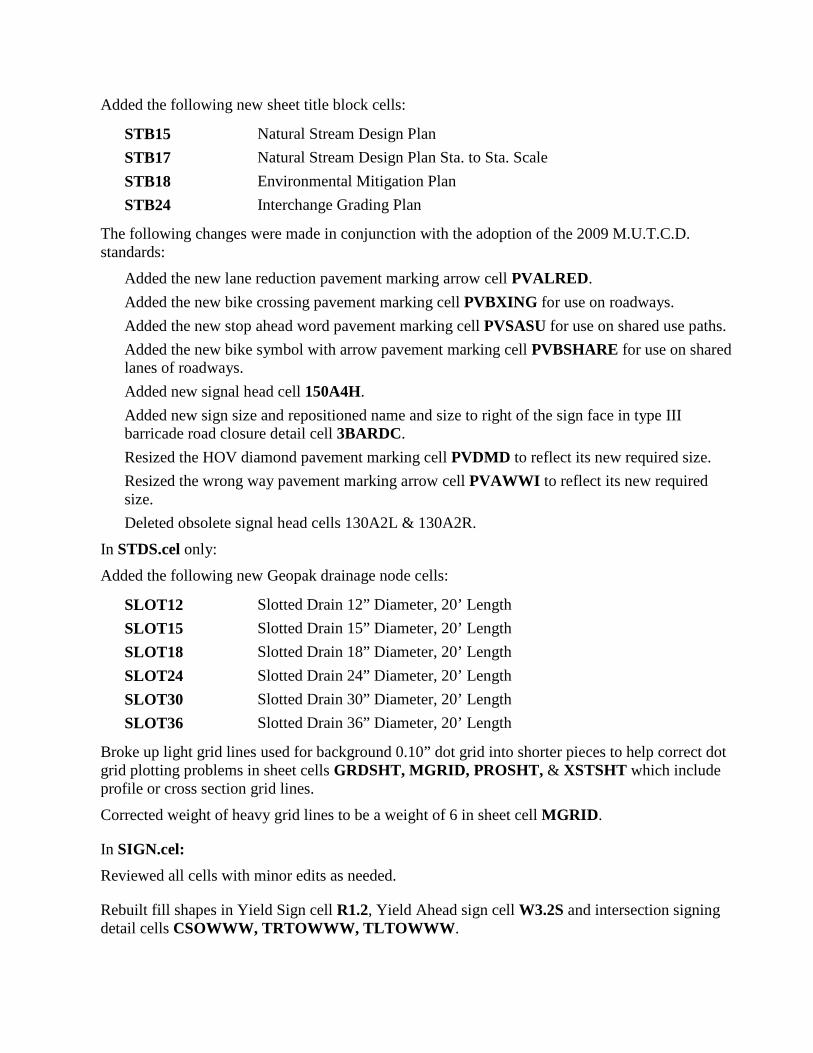
Added the following new sheet title block cells:
STB15 Natural Stream Design Plan STB17 Natural Stream Design Plan Sta. to Sta. Scale STB18 Environmental Mitigation Plan STB24 Interchange Grading Plan
The following changes were made in conjunction with the adoption of the 2009 M.U.T.C.D. standards:
Added the new lane reduction pavement marking arrow cell PVALRED. Added the new bike crossing pavement marking cell PVBXING for use on roadways. Added the new stop ahead word pavement marking cell PVSASU for use on shared use paths. Added the new bike symbol with arrow pavement marking cell PVBSHARE for use on shared lanes of roadways. Added new signal head cell 150A4H. Added new sign size and repositioned name and size to right of the sign face in type III barricade road closure detail cell 3BARDC. Resized the HOV diamond pavement marking cell PVDMD to reflect its new required size. Resized the wrong way pavement marking arrow cell PVAWWI to reflect its new required size. Deleted obsolete signal head cells 130A2L & 130A2R.
In STDS.cel only:
Added the following new Geopak drainage node cells:
SLOT12 Slotted Drain 12” Diameter, 20’ Length SLOT15 Slotted Drain 15” Diameter, 20’ Length SLOT18 Slotted Drain 18” Diameter, 20’ Length SLOT24 Slotted Drain 24” Diameter, 20’ Length SLOT30 Slotted Drain 30” Diameter, 20’ Length SLOT36 Slotted Drain 36” Diameter, 20’ Length
Broke up light grid lines used for background 0.10” dot grid into shorter pieces to help correct dot grid plotting problems in sheet cells GRDSHT, MGRID, PROSHT, & XSTSHT which include profile or cross section grid lines.
Corrected weight of heavy grid lines to be a weight of 6 in sheet cell MGRID.
In SIGN.cel: Reviewed all cells with minor edits as needed.
Rebuilt fill shapes in Yield Sign cell R1.2, Yield Ahead sign cell W3.2S and intersection signing detail cells CSOWWW, TRTOWWW, TLTOWWW.
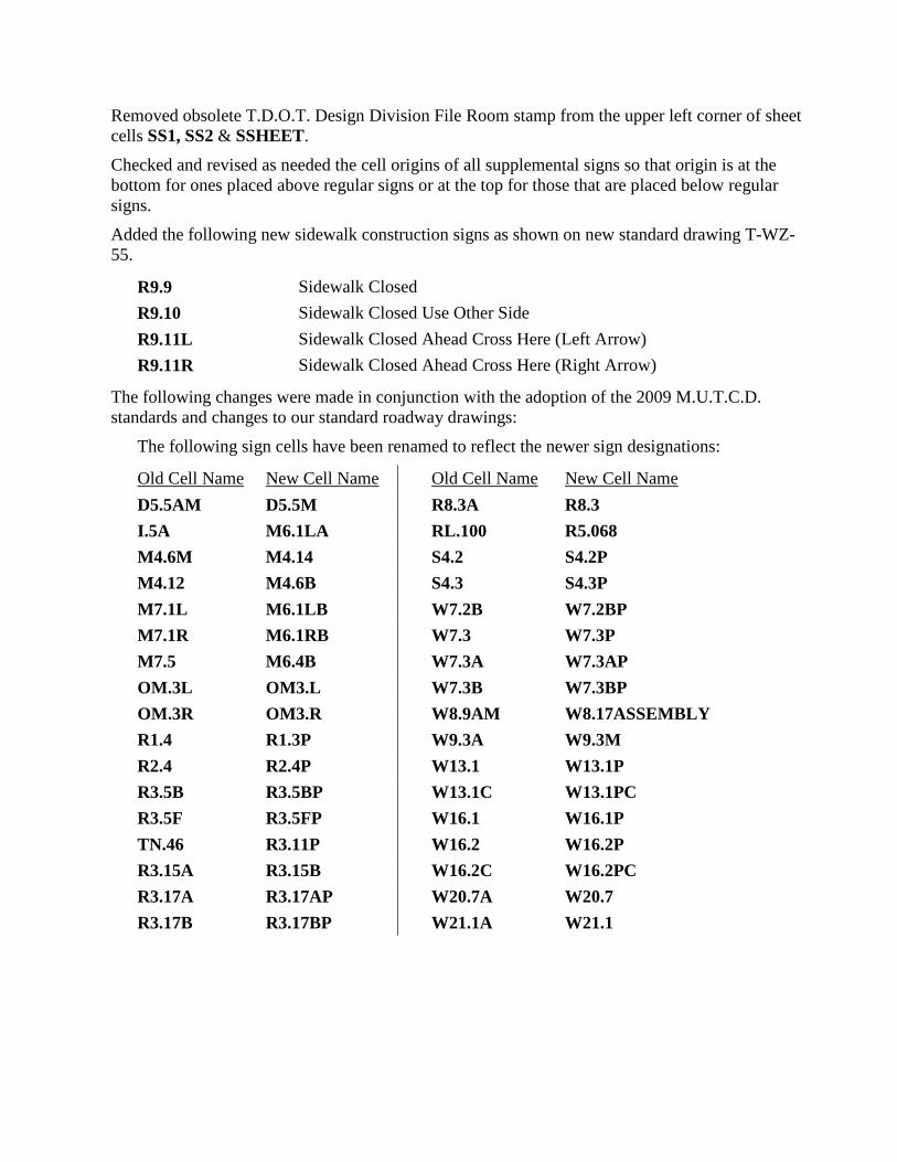
Removed obsolete T.D.O.T. Design Division File Room stamp from the upper left corner of sheet cells SS1, SS2 & SSHEET.
Checked and revised as needed the cell origins of all supplemental signs so that origin is at the bottom for ones placed above regular signs or at the top for those that are placed below regular signs.
Added the following new sidewalk construction signs as shown on new standard drawing T-WZ-55.
R9.9 Sidewalk Closed R9.10 Sidewalk Closed Use Other Side R9.11L Sidewalk Closed Ahead Cross Here (Left Arrow) R9.11R Sidewalk Closed Ahead Cross Here (Right Arrow)
The following changes were made in conjunction with the adoption of the 2009 M.U.T.C.D. standards and changes to our standard roadway drawings:
The following sign cells have been renamed to reflect the newer sign designations:
Old Cell Name New Cell Name Old Cell Name New Cell Name D5.5AM D5.5M R8.3A R8.3 I.5A M6.1LA RL.100 R5.068 M4.6M M4.14 S4.2 S4.2P M4.12 M4.6B S4.3 S4.3P M7.1L M6.1LB W7.2B W7.2BP M7.1R M6.1RB W7.3 W7.3P M7.5 M6.4B W7.3A W7.3AP OM.3L OM3.L W7.3B W7.3BP OM.3R OM3.R W8.9AM W8.17ASSEMBLY R1.4 R1.3P W9.3A W9.3M R2.4 R2.4P W13.1 W13.1P R3.5B R3.5BP W13.1C W13.1PC R3.5F R3.5FP W16.1 W16.1P TN.46 R3.11P W16.2 W16.2P R3.15A R3.15B W16.2C W16.2PC R3.17A R3.17AP W20.7A W20.7 R3.17B R3.17BP W21.1A W21.1
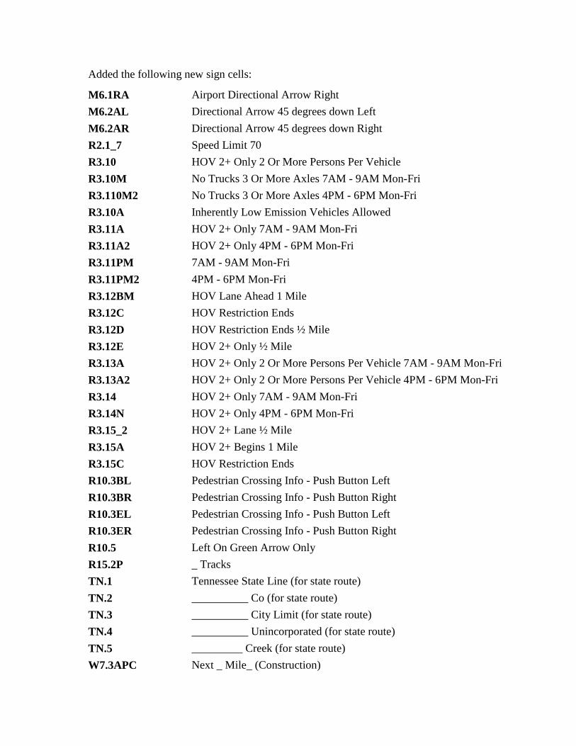
Added the following new sign cells:
M6.1RA Airport Directional Arrow Right M6.2AL Directional Arrow 45 degrees down Left M6.2AR Directional Arrow 45 degrees down Right R2.1_7 Speed Limit 70 R3.10 HOV 2+ Only 2 Or More Persons Per Vehicle R3.10M No Trucks 3 Or More Axles 7AM - 9AM Mon-Fri R3.110M2 No Trucks 3 Or More Axles 4PM - 6PM Mon-Fri R3.10A Inherently Low Emission Vehicles Allowed R3.11A HOV 2+ Only 7AM - 9AM Mon-Fri R3.11A2 HOV 2+ Only 4PM - 6PM Mon-Fri R3.11PM 7AM - 9AM Mon-Fri R3.11PM2 4PM - 6PM Mon-Fri R3.12BM HOV Lane Ahead 1 Mile R3.12C HOV Restriction Ends R3.12D HOV Restriction Ends ½ Mile R3.12E HOV 2+ Only ½ Mile R3.13A HOV 2+ Only 2 Or More Persons Per Vehicle 7AM - 9AM Mon-Fri R3.13A2 HOV 2+ Only 2 Or More Persons Per Vehicle 4PM - 6PM Mon-Fri R3.14 HOV 2+ Only 7AM - 9AM Mon-Fri R3.14N HOV 2+ Only 4PM - 6PM Mon-Fri R3.15_2 HOV 2+ Lane ½ Mile R3.15A HOV 2+ Begins 1 Mile R3.15C HOV Restriction Ends R10.3BL Pedestrian Crossing Info - Push Button Left R10.3BR Pedestrian Crossing Info - Push Button Right R10.3EL Pedestrian Crossing Info - Push Button Left R10.3ER Pedestrian Crossing Info - Push Button Right R10.5 Left On Green Arrow Only R15.2P _ Tracks TN.1 Tennessee State Line (for state route) TN.2 __________ Co (for state route) TN.3 __________ City Limit (for state route) TN.4 __________ Unincorporated (for state route) TN.5 _________ Creek (for state route) W7.3APC Next _ Mile_ (Construction)
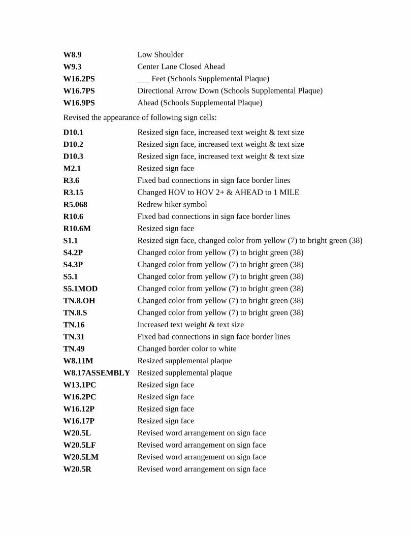
W8.9 Low Shoulder W9.3 Center Lane Closed Ahead W16.2PS ___ Feet (Schools Supplemental Plaque) W16.7PS Directional Arrow Down (Schools Supplemental Plaque) W16.9PS Ahead (Schools Supplemental Plaque)
Revised the appearance of following sign cells:
D10.1 Resized sign face, increased text weight & text size D10.2 Resized sign face, increased text weight & text size D10.3 Resized sign face, increased text weight & text size M2.1 Resized sign face R3.6 Fixed bad connections in sign face border lines R3.15 Changed HOV to HOV 2+ & AHEAD to 1 MILE R5.068 Redrew hiker symbol R10.6 Fixed bad connections in sign face border lines R10.6M Resized sign face S1.1 Resized sign face, changed color from yellow (7) to bright green (38) S4.2P Changed color from yellow (7) to bright green (38) S4.3P Changed color from yellow (7) to bright green (38) S5.1 Changed color from yellow (7) to bright green (38) S5.1MOD Changed color from yellow (7) to bright green (38) TN.8.OH Changed color from yellow (7) to bright green (38) TN.8.S Changed color from yellow (7) to bright green (38) TN.16 Increased text weight & text size TN.31 Fixed bad connections in sign face border lines TN.49 Changed border color to white W8.11M Resized supplemental plaque W8.17ASSEMBLY Resized supplemental plaque W13.1PC Resized sign face W16.2PC Resized sign face W16.12P Resized sign face W16.17P Resized sign face W20.5L Revised word arrangement on sign face W20.5LF Revised word arrangement on sign face W20.5LM Revised word arrangement on sign face W20.5R Revised word arrangement on sign face

W20.5RF Revised word arrangement on sign face W20.5RM Revised word arrangement on sign face
Deleted the following obsolete sign cells:
R1.3 R3.11AM R3.11AM2 R3.11AM3 R3.11AM4 R3.12A R3.12M R3.14M R3.14M2 R4.6 W8.9A
• Data.exe Added the following new colors to STDCOLOR.TBL for use in the new T.D.O.T. logo: 69(royal blue, 70(very slightly off-white), 71(lighter red). Note that absolute white, color 0, could not be used since that color automatically defaults to black when printing.
• Dgnlib.exe Updated TDOTmain.dgnlib with the following new levels for proposed roadway model production. Each level has a default material defined so that model graphics placed on these levels are automatically rendered with the specified material.
DESIGN - MODEL - Aggregate DESIGN - MODEL - Asphalt DESIGN - MODEL - Concrete DESIGN - MODEL - Grass DESIGN - MODEL - Rip-Rap DESIGN - MODEL - Truck Apron Pavers
Updated TDOTmain.dgnlib with the following new level filters for use on Erosion Prevention and Sediment Control sheets.
Sheets - EPSC Clearing and Grubbing Sheets - EPSC Intermediate Grading Sheets - EPSC Final Construction Obsolete level filters Sheets - Erosion Control and Sheets - Erosion Control - References were deleted.
Updated TDOTmain.dgnlib with the following new level filters for use bhy Survey when checking their work.
Survey - Drainage - Topo Control Survey - DTM - Topo Control Survey - Field Topo Survey - Profile - Topo Control
In TDOTmain.dgnlib, all Signalization text styles re-sized for default use at 20 scale.
In TDOTmain.dgnlib, corrected color of text style Utilities Lighting -Exist. to 2 (manila).
In TDOTmain.dgnlib, corrected color of text style Transportation Urban - Exist. to 11 (light purple).
Regenerated TDOTV8mainOnTheFly.csv in V8i with new levels.
• Image.exe Added new image files Phase Stamp - P S & E Review.jpg and Phase Stamp - Constructability Field Review.jpg.
Deleted obsolete image file Phase Stamp - Construction Field Review.jpg.
• Macros.exe This obsolete download file has been removed. All functionality of programs has been replaced with new visual basic applications.
• Mdl.exe This obsolete download file has been removed. All functionality of programs has been replaced with new visual basic applications.
• Plotcfg.exe (old Pltdrv.exe) All old MicroStation Print plot driver files have been replaced with new MicroStation V8i Print plot configuration files. The names are the same except for the extension which is now pltcfg.
Added new PDF sheet sizes PDF Regular Full, PDF XS Full & PDF Permit Full to plot config files Tdotpdfful.pltcfg & Tdotpdffulc.pltcfg (full size color) which are used to generate PDF files using MicroStation Print or MicroStation Print Organizer. Also added new PDF sheet sizes PDF Regular Half & PDF XS Half to plot config file Tdotpdfhaf.pltcfg.
• Seed.exe Updated all seed files with latest color table, levels, level filters and text styles.
Reset all seed files so that Outlined fills default to fill color 0 (white). Previously the fill color was set to ByLevel Color which yielded odd results in many cases.
All seed files with embedded Word documents have been updated to most current specifications of T.D.O.T. Roadway Design Division Roadway Design Guidelines. Embedded documents have been converted to Office 2010 documents. Also removed obsolete T.D.O.T. Design Division File Room stamp from sheets in these files.
• Symb.exe The appearance of line style FENCE HIGH VISIBILTY has been revised, An upcoming revision of standard drawing S-F-1 for high visibility fence will change the appearance of that plans item to show as “* HVF * HVF ” as is done for silt fence or other EPSC measures. We have updated this custom line style to appear as such.
Added the following new line styles:
BIKE PEDESTRIAN SAFETY RAIL
Prop. bike/pedestrian safety rail for use along shared use paths
PVMT MRK 3-9 W 12" Pavement marking stripe style for white 12” wide stripe
with 3’ dash and 9’ gaps for use at expressway & freeway int4erchanges
PVMT MRK SOL Y 8" Pavement marking stripe style for solid yellow 8” wide stripe for temporary use in traffic control plans
ROCK WALL FACE Existing rock wall with alignment along the face rather than the center as it was in the older style ROCK WALL which was used prior to V8i. This style replaces the use of that one for easier data acquisition in the field. Note that field points should be gathered from left to right.
SIDE DRAIN 15" PROP Proposed 15” side drain ST SEWER 12" PROP CMP Proposed 12” storm sewer corrugated metal pipe set up
for use with slotted drains ST SEWER 15" PROP CMP Proposed 15” storm sewer corrugated metal pipe set up
for use with slotted drains ST SEWER 18" PROP CMP Proposed 18” storm sewer corrugated metal pipe set up
for use with slotted drains ST SEWER 24" PROP CMP Proposed 24” storm sewer corrugated metal pipe set up
for use with slotted drains ST SEWER 30" PROP CMP Proposed 30” storm sewer corrugated metal pipe set up
for use with slotted drains ST SEWER 36" PROP CMP Proposed 36” storm sewer corrugated metal pipe set up
for use with slotted drains ST SEWERM 300 PROP CMP Proposed 300 mm storm sewer corrugated metal pipe set
up for use with slotted drains ST SEWERM 375 PROP CMP Proposed 375 mm storm sewer corrugated metal pipe set
up for use with slotted drains ST SEWERM 450 PROP CMP Proposed 450 mm storm sewer corrugated metal pipe set
up for use with slotted drains ST SEWERM 600 PROP CMP Proposed 600 mm storm sewer corrugated metal pipe set
up for use with slotted drains ST SEWERM 750 PROP CMP Proposed 750 mm storm sewer corrugated metal pipe set
up for use with slotted drains ST SEWERM 900 PROP CMP Proposed 900 mm storm sewer corrugated metal pipe set
up for use with slotted drains ST SEWER 12" PROP UNSPECIFIED
Proposed 12” storm sewer, unspecified pipe type
ST SEWER 15" PROP UNSPECIFIED
Proposed 15” storm sewer, unspecified pipe type
• TDOTinterface.exe Old interface file replaced with new V8i dgnlib file tdot.dgnlib for interface settings.
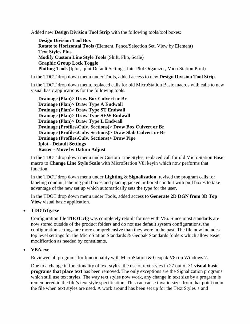
Added new Design Division Tool Strip with the following tools/tool boxes:
Design Division Tool Box Rotate to Horizontal Tools (Element, Fence/Selection Set, View by Element) Text Styles Plus Modify Custom Line Style Tools (Shift, Flip, Scale) Graphic Group Lock Toggle Plotting Tools (Iplot, Iplot Default Settings, InterPlot Organizer, MicroStation Print)
In the TDOT drop down menu under Tools, added access to new Design Division Tool Strip.
In the TDOT drop down menu, replaced calls for old MicroStation Basic macros with calls to new visual basic applications for the following tools.
Drainage (Plan)> Draw Box Culvert or Br Drainage (Plan)> Draw Type A Endwall Drainage (Plan)> Draw Type ST Endwall Drainage (Plan)> Draw Type SEW Endwall Drainage (Plan)> Draw Type L Endwall Drainage (Profiles\Culv. Sections)> Draw Box Culvert or Br Drainage (Profiles\Culv. Sections)> Draw Slab Culvert or Br Drainage (Profiles\Culv. Sections)> Draw Pipe Iplot - Default Settings Raster - Move by Datum Adjust
In the TDOT drop down menu under Custom Line Styles, replaced call for old MicroStation Basic macro to Change Line Style Scale with MicroStation V8i keyin which now performs that function.
In the TDOT drop down menu under Lighting & Signalization, revised the program calls for labeling conduit, labeling pull boxes and placing jacked or bored conduit with pull boxes to take advantage of the new set up which automatically sets the type for the user.
In the TDOT drop down menu under Tools, added access to Generate 2D DGN from 3D Top View visual basic application.
• TDOTcfg.exe Configuration file TDOT.cfg was completely rebuilt for use with V8i. Since most standards are now stored outside of the product folders and do not use default system configurations, the configuration settings are more comprehensive than they were in the past. The file now includes top level settings for the MicroStation Standards & Geopak Standards folders which allow easier modification as needed by consultants.
• VBA.exe Reviewed all programs for functionality with MicroStation & Geopak V8i on Windows 7.
Due to a change in functionality of text styles, the use of text styles in 27 out of 31 visual basic programs that place text has been removed. The only exceptions are the Signalization programs which still use text styles. The way text styles now work, any change in text size by a program is remembered in the file’s text style specification. This can cause invalid sizes from that point on in the file when text styles are used. A work around has been set up for the Text Styles + and
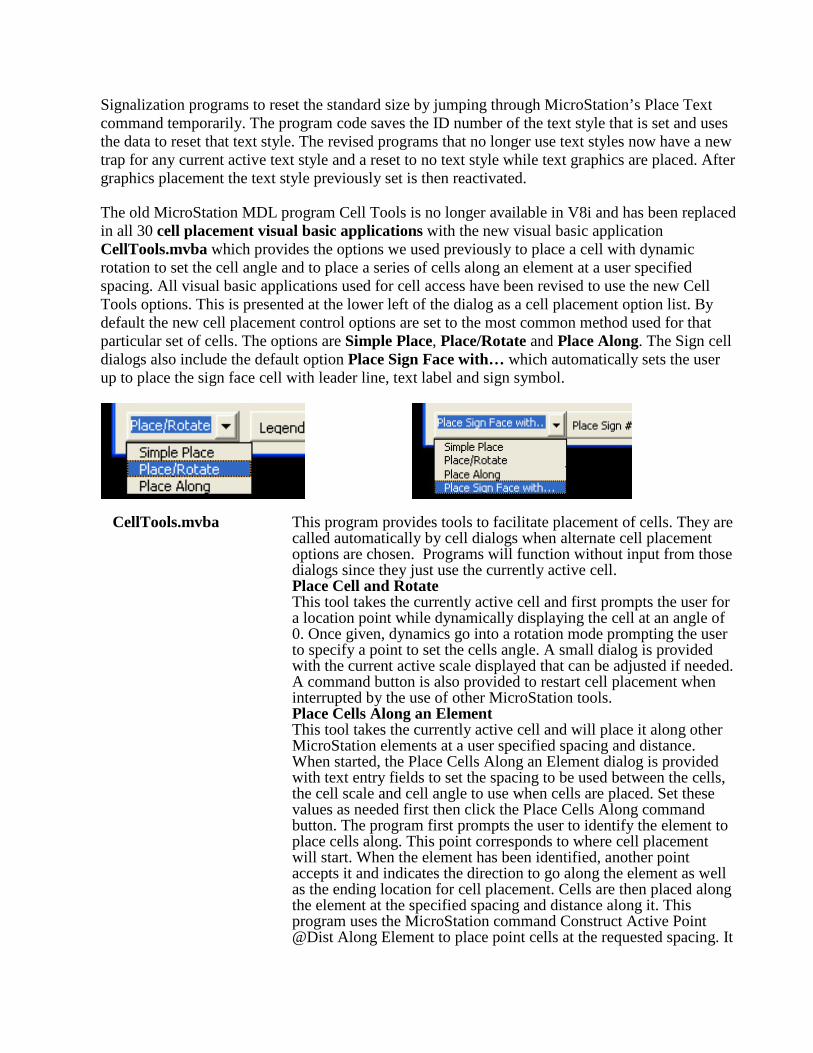
Signalization programs to reset the standard size by jumping through MicroStation’s Place Text command temporarily. The program code saves the ID number of the text style that is set and uses the data to reset that text style. The revised programs that no longer use text styles now have a new trap for any current active text style and a reset to no text style while text graphics are placed. After graphics placement the text style previously set is then reactivated.
The old MicroStation MDL program Cell Tools is no longer available in V8i and has been replaced in all 30 cell placement visual basic applications with the new visual basic application CellTools.mvba which provides the options we used previously to place a cell with dynamic rotation to set the cell angle and to place a series of cells along an element at a user specified spacing. All visual basic applications used for cell access have been revised to use the new Cell Tools options. This is presented at the lower left of the dialog as a cell placement option list. By default the new cell placement control options are set to the most common method used for that particular set of cells. The options are Simple Place, Place/Rotate and Place Along. The Sign cell dialogs also include the default option Place Sign Face with… which automatically sets the user up to place the sign face cell with leader line, text label and sign symbol.
CellTools.mvba This program provides tools to facilitate placement of cells. They are called automatically by cell dialogs when alternate cell placement options are chosen. Programs will function without input from those dialogs since they just use the currently active cell. Place Cell and Rotate This tool takes the currently active cell and first prompts the user for a location point while dynamically displaying the cell at an angle of 0. Once given, dynamics go into a rotation mode prompting the user to specify a point to set the cells angle. A small dialog is provided with the current active scale displayed that can be adjusted if needed. A command button is also provided to restart cell placement when interrupted by the use of other MicroStation tools. Place Cells Along an Element This tool takes the currently active cell and will place it along other MicroStation elements at a user specified spacing and distance. When started, the Place Cells Along an Element dialog is provided with text entry fields to set the spacing to be used between the cells, the cell scale and cell angle to use when cells are placed. Set these values as needed first then click the Place Cells Along command button. The program first prompts the user to identify the element to place cells along. This point corresponds to where cell placement will start. When the element has been identified, another point accepts it and indicates the direction to go along the element as well as the ending location for cell placement. Cells are then placed along the element at the specified spacing and distance along it. This program uses the MicroStation command Construct Active Point @Dist Along Element to place point cells at the requested spacing. It

also uses the MicroStation command Measure Distance Along an Element to calculate the distance where cell placement should end. Note that currently the scale used for point cells in MicroStation V8i is the reciprocal of the current active scale. For this reason the program temporarily changes the active scale to yield the correct scale when the cells are placed as points. After cell placement the active scale is reset to its normal value. For example with a desired scale of 50 the program will set it as 1/50 or 0.02.
Also made the following revisions to all cell placement visual basic applications:
Reset border style to None on cell image window of main dialog to prevent display problems for some cells in V8i.
Reset the Cancel button Default setting to False and set default focus to the cell list on the dialog. In V8i the True setting and default focus on the Cancel button caused the dialog to be closed if the Simple Place option was active and the keyboard Enter key was clicked to change the angle or scale in MicroStation's Tool Settings dialog.
Made the following revisions to all sign cell placement visual basic applications:
Reset Sign Symbol option to be on by default and added code to allow the angle of the sign symbol to be set graphically at the time of placement.
Added new option to place permanent sign text labels as a sign number or with the sign's name and size.
Changed the Metric Plot Scale field to reflect and change the scale in English or Metric files.
Added another size option for Multi-Lane conventional roadways as shown in the 2009 M.U.T.C.D. Changed the first size option to indicate that it is for Single lane conventional roadways. Updated all sizes in code to reflect values presented in the M.U.T.C.D. The values given for Interstate roadways reflect those listed for interstates or freeways if specified. Otherwise they specify the values where provided for expressways or simply as oversized signs.
Updated all sign names listed to reflect them as shown in the 2009 M.U.T.C.D. and our standard roadway drawings. See the cell revision listing of sign cells for specific sign changes and additions in these programs.
Added the following new programs to replace obsolete MicroStation Basic macro programs with enhancements as noted:
DrawBoxPlan.mvba Program now includes: Option to place label as text only or as a flag with terminator choices is now provided. Added dynamics for structure and text label placement.
DrawBoxProfile.mvba Program now includes: Option for placement as Existing or Proposed structure is now provided. Added access to the Data Point Station Elevation tool so that flow point can be set by station & elevation.
Added dynamics for structure and text label placement. Proposed box structures are now created at a weight of 6 and set up as group holes so that structure slabs and walls are filled for better visibility in the plans.
DrawSlabProfile.mvba Program now includes: Option for placement as Existing or Proposed structure is now provided. Added access to the Data Point Station Elevation tool so that flow point can be set by station & elevation. Added dynamics for structure and text label placement. Proposed slab structures are now created at a weight of 6 and set up as a filled shape for better visibility in the plans.
DrawPipeProfile.mvba Program now includes: Option for placement as Existing or Proposed structure is now provided. Added access to the Data Point Station Elevation tool so that flow point can be set by station & elevation. Program now includes dynamics for structure and text label placement. Proposed pipes are now created at a weight of 6 for better visibility in the plans.
DrawTypeAEndwall.mvba DrawTypeLEndwall.mvba DrawTypeSDEndwall.mvba DrawTypeSTEndwall.mvba Programs now include:
Dynamic display of endwall graphics during placement. Revised code so that all dialog changes are immediately applied during placement. Replaced code that wrote endwall data items to a CSV file with new programming to write endwall information as Geopak adhoc data directly on endwall line string. Added new dialog and programming code to identify endwalls and read the Geopak adhoc data written to them by the Draw Endwall tool. This can be used to check current endwalls that have been placed in the project to determine if they are correct and reflect the latest proposed roadway side slopes, etc. This data is read by computation programs to compile pipe and endwall quantities as requested. Added quote marks around the endwall type designation that is stored with the endwall graphics for later use in tabulation to match requirements as shown in the TDOOT Roadway Design Division Drainage Manual.
DrawTypeSDEndwall.mvba Also made the following revisions to this program: Updated program to reflect values as shown on new standard roadway drawing D-SEW-1A and revised drawing D-SEW-12D. This included adjustments to headwall and wingwall lengths as well as changes to concrete, reinforcing steel and structural steel quantities. Grates are now optional for 15 to 18 inch pipes at a slope of 6:1 so a
new option for the grate was added to control its placement. Additional programming code was added to dialog controls to automatically set the grate option based on other control values with warning messages if that option was set to an invalid value based on the other controls. Revised standard drawings referenced on the dialog title bar to reflect the new standards. Enabled and populated the pipe types option on the main dialog to allow use with cross drains or connecting to storm sewer systems. Changed endwall type designations that are stored with the endwall graphics to "SEW" & "12D" Also added applicable standard roadway drawing numbers D-PE-15A thru D-PE-48B to type "SEW" endwall data written to graphics.
DrawVehicleTrajectoryPath.mvba Program logic for this application was adapted from the original MicroStation Basic version with no enhancements to its original functionality.
Generate2Dfrom3DTop.mvba Eliminated the need to get a data point from the user.
IplotSet.mvba Restricted the listing of settings files to leave out the current version of iplot.set as well as settings files used only with InterPlot Organizer and not with Iplot. File list dialog is no longer modal and can remain open for later use as needed. Selection of the settings file automatically makes it active with a success message which displays on the dialog to indicate the settings file that was activated. Revised folder path for settings files to match new Windows 7 path for InterPlot V8i.
mfc2dtm.mvba The change symbology command used to change element symbologies to that of breaklines was failing so it was replaced with separate commands to change color, style and weight.
MoveRasterbyDatumAdjust.mvba Program now includes: Eliminated the need to get a data point from the user by using the origins of the raster file attachments. Set up a separate command button and code for the Move Raster(s) Back to Original Location function. Added a command button to open the Raster Manager dialog. Changed text on dialog to indicate that 1 or more raster attachments may be moved at the same time.
Revised the following individual programs: BatchTextEditor.mvba Completely rebuilt code to call program and set up text editing
options since the Find/Replace Text tool had been completely replaced with a new version of that program. Added Find/Replace Text options Match Case, Whole Words, Use Regular Expressions and Change In Cells to duplicate the options provided by the regular tool and give the user the capability to use these as needed. All are on by default except for Use Regular Expressions.
Expanded DGN file list box vertically on dialog to display more filenames.
CodePavementLayers.mvba Revised to place all graphics on level DESIGN - TRANSPORTATION - Text.
ConstructionSignCells.mvba Added L or R to sign label names to indicate left or right for signs W24-1, W24-1A and W24-1B.
DPprofile.mvba Changed the way text justification was applied, now uses keyins to set those rather than direct manipulation during creation.
DrainagePlanCells.mvba Replaced obsolete MicroStation Basic calls to programs that placed box culverts/bridges and type A, ST, L & SD endwalls with calls to new visual basic applications that are now used to place those structures. Revised command button text to reflect that SD endwalls are now called SEW endwalls.
DrainageProfileCells.mvba Added access to the Data Point Station Elevation tool so that cell location points can be set by station & elevation. Replaced obsolete MicroStation Basic calls to draw box, slab or pipe structures on the profile with calls to new visual basic applications that are now used to place those structures.
DrawHandicapRamp.mvba Corrected use of array variable for storing arc end points from complex strings n module IdenitfyRoadwayCurb to use a pre-dimensioned array. If a complex string was encountered where the first element was an arc it would fail since it attempted to use array dimensions that had not yet been set. Updated for use on Windows 7 with change to color used for background of drop down option lists at top of dialog to maintain them as white.
DrawTypeUEndwall.mvba Revised code so that all dialog changes are immediately applied during placement. Replaced code that wrote endwall data items to a CSV file with new programming to write endwall information as Geopak adhoc data directly on endwall line string. Added new dialog and programming code to identify endwalls and read the Geopak adhoc data written to them by the Draw Endwall tool. This can be used to check current endwalls that have been placed in the project to determine if they are correct and reflect the latest proposed roadway side slopes, etc. This data is read by computation programs to compile pipe and endwall quantities as requested. Updated program to reflect values as shown on new standard roadway drawings D-PE-15A thru D-PE-48A. This included the addition of the 15" pipe size and adjustments to concrete and reinforcing steel quantities. Additional programming code was added to dialog controls to automatically set the grate option based on other control values with warning messages if that option was set to an invalid value based on the other controls. Also revised standard drawings referenced on dialog title bar to
reflect the new standards. Separated side slope options 2:1 and 1.5:1 in the dialog & program coding. Added quote marks around the endwall type designation that is stored with the endwall graphics for later use in tabulation to match requirements as shown in the TDOOT Roadway Design Division Drainage Manual. Also corrected the form variable name for the endwall type in the module clsReadEndwallData used in reading and populating those values in the Review Endwall Data dialog.
ErosionControlCells.mvba Revised title on dialog to specify use for Erosion Prevention Sediment Control.
ErosionControlLegendCells.mvba Revised title on dialog to specify use for Erosion Prevention Sediment Control. Also added new legend cell option for High Visibility Fence.
HA_IntersectLabel.mvba Revised dynamics mode used. Old mode that was specified no longer acted as before so dynamics were revised to use the default mode specified by MicroStation. Updated for use on Windows 7 with change to color used for background and border of label preview window to maintain it as black.
LabelConduit.mvba Added quote marks around the text style name used in the text annotation modules to ensure activation when spaces were included in the name. Added trap and reset for text style settings to prevent the special settings used for annotation graphics from overwriting default values for the text style. Set up separate program calls for Lighting and Signalization so that the type needed is automatically set as true.
LabelEPSCStormWaterOutfalls.mvba Added option on dialog and in programing code to handle auto incrementing of the suffix text instead of number for use in cases where sub-outfalls need to be labeled. Suffixes are incremented from A to Z and then from AA to ZZ if needed.
LabelPullBox.mvba Added quote marks around the text style name used in the text annotation modules to ensure activation when spaces were included in the name. Added trap and reset for text style settings to prevent the special settings used for annotation graphics from overwriting default values for the text style. Set up separate program calls for Lighting and Signalization so that the type needed is automatically set as true.
LightingCells.mvba Revised the program calls for labeling conduit, labeling pull boxes and placing jacked or bored conduit with pull boxes to take advantage of the new set up which automatically sets the lighting type for the user.
PavementMarkingCells.mvba Added pavement marking cells PVALRED (Lane Reduction Arrow), PVBXING (Bike Crossing), PVBSHARE (Bike Shared Lane) and PVHXING (Highway Crossing for Shared Use Path).
PermitFormsCells.mvba Changed order of cell list so that most used were at the top. PlaceJackedBoredConduit.mvba Set up separate program calls for Lighting and
Signalization so that the type needed is automatically set as true. PlaceVegetation.mvba Corrected prompt for vegetation lines to specify digitizing points in a
clockwise direction. PlanPhaseCells.mvba Added access to new P. S. & E. Review stamp cell and revised list to
specify Constructability Field Review rather than Const. PublicHearingCells.mvba Removed option for TDOT logo with Go since that is no longer used
with new TDOT logo. RegulatorySignCells.mvba Added L or R to sign label names to indicate left or right for
signs R10-3B and R10-3E. SetTextParametersAS.mvba Changed the order of the code so that text size is set first ensuring
that the correct line spacing was set since it now uses the current text size to set a decimal value of text size divided by the line spacing requested for the actual value used. Removed code to set text length since it is no longer a setting that is used. Updated for use on Windows 7 with change to color used for background of drop down text size option list to maintain it as white.
SheetTitleCells.mvba Added access to new sheet title cells: Environmental Mitigation Plan, Interchange Grading Plan and Natural Stream Design Plan.
SignalizationDeviceCells.mvba In module SignalDevicecells: Added quote marks around the text style name used in the text annotation modules to ensure activation when spaces were included in the name. Added trap and reset for text style settings to prevent the special settings used for annotation graphics from overwriting default values for the text style. Also revised signal head number label tool to calculate radius of circle while in dynamics and before placement to trap when additional numbers or letters are added in the dialog which require a larger circle. Revised the program calls for labeling conduit, labeling pull boxes and placing jacked or bored conduit with pull boxes to take advantage of the new set up which automatically sets the signalization type for the user. In module PlaceMastArm: Removed one point that was being sent to MicroStation to initiate the rotation of the mast arm to set its angle. The rotate command no longer required as many points which caused it to set the angle as it was placed initially not allowing the user to set the angle required. Also added dynamics code so that mast arm is shown at the specified length during identification of the start point.
SignalHeadCells.mvba Added quote marks around the text style name used in the text annotation modules to ensure activation when spaces were included in the name. Added trap and reset for text style settings to prevent the special settings used for annotation graphics from overwriting default values for the text style.
Deleted obsolete signal heads 130A2L & 130A2R and added new signal head 150A4H.
SignalHeightAttachmentDiagram.mvba Added quote marks around the text style name used in the text annotation modules to ensure activation when spaces were included in the name. Added trap and reset for text style settings to prevent the special settings used for annotation graphics from overwriting default values for the text style.
StormDrainagePipeLabel.mvba Added new traps to identify 12"/300 mm & 15"/375 mm concrete or unspecified pipe types and the following sizes of corrugated metal pipes: 12"/300 mm, 15"/375 mm, 18"/450 mm, 24"/600 mm, 30"/750 mm & 36/900 mm". The corrugated metal pipes include CMP in the label text which is set up and were specifically added to cover their use with slotted drains.
SurveyProjectWorkFlowToolbox.mvba Added Draw Ancillary Features command button under the Graphics Display tool group and adjusted Min/Max control for added length of dialog.
TDOTDesignDivToolbox.mvba Removed obsolete Cell Tools command button and replaced with 2 new command buttons to access new tools, Place Cell & Rotate and Place Cells Along, from new visual basic application CellTools.mvba. Replaced call to obsolete visual basic application, Change Line Style Scale, with a standard MicroStation key in which now performs the same function. Replaced calls to old MicroStation Basic macros, Set Iplot Default Settings & Move Raster by Datum Adjustment Factor, with calls to new MicroStation vba programs that perform these functions. Removed command button to access MicroStation tool box Drafting Tools which no longer exists as such. Added new section with 2 command buttons for Classic Toolboxes; MicroStation Main and Geopak Road Tools. Renamed options with the text "Erosion Control" as EPSC under the cell dialog list.
TextstylesPlus.mvba Added quote marks around the text style name used in the text annotation modules to ensure activation when spaces were included in the name. Added code to save the ID number of the text style that is set and to use that data to reset that text style after label graphics are placed. To accomplish this reset it was necessary to start the Place Text command temporarily. This was done to prevent the special settings used for graphics from overwriting default values for the text style. Corrected color that was set for text styles Transportation Urban - Exist. and Utilities Lighting - Exist. Added a new variable for the base scale that text styles are based on to trap for text style Signalization - Prop. which is stored at a 20 scale unlike all others which are set up at 50 scale.
TrafficFlowDiagramCells.mvba Added new traffic flow diagrams for semidirect interchanges with semidirect ramp connections on left, right or both sides.
UpdateProjectCriteriaFiles.mvba Added "/Y" to the copy command line that is set up to update each criteria file to auto-confirm the overwrite of the current file in the project.
V8_Import.mvba Added additional unit labels, sf & SF, to trap for files to change units to survey feet with standard settings. Changed text style import section to first select and delete current standard text styles to ensure that all of them are updated to current settings. Previously only new text styles were imported which did not allow updates to current ones. The user is prompted to approve any text style deletion if it is used in the file. If approved, the text using it is reset to style “None”, the style is deleted and updated. If refused, the text will retain its text style definition but the text style is not updated. Added cell library extensions to file type list for processing.
VA_Labeler.mvba Added code to Label Vertical Alignment function to attach the profile to the chain to correct problems with profiles occurring beyond station equations. This fix also negated the need for old code that adjusted all profile point locations in those subroutines which has now been removed. It was also necessary to alter the Calculate Low or High Point subroutine to use the distance along value rather than the station value it had at that point to yield the correct elevation due to the attach profile to chain change. Removed RD and RD01 K value options from Label Vertical Alignment dialog and all source code that used those options since the RD standards are now obsolete and only RD01 standards should be used. Also revised directory location for K Value Text File VALabel_Speed_kvl.txt to reflect new Windows 7 set up.
VerticalCurveDesign.mvba Removed RD and RD01 K value options from Vertical Curve Design Tool dialog and all source code that used those options since the RD standards are now obsolete and only RD01 standards should be used. Also revised directory location for K Value Text File VALabel_Speed_kvl.txt to reflect new Windows 7 set up.
XSTextstylesPlus.mvba Added quote marks around the text style name used in the text annotation modules to ensure activation when spaces were included in the name. Added code to save the ID number of the text style that is set and to use that data to reset that text style after label graphics are placed. To accomplish this reset it was necessary to start the Place Text command temporarily. This was done to prevent the special settings used for graphics from overwriting default values for the text style
Deleted obsolete program ChangeLinestyleScale.mvba which is now covered by MicroStation’s custom line style control functions.
Geopak
• GeopakStandards.exe In D&C Manager (tdot.ddb & tdotmetric.ddb)
Reviewed all items for functionality with V8i.
With Geopak V8i, all offsets for line work annotation of chains was changed to be adjusted by the scale value rather than a hard coded value that ignored the current scale setting. To correct for this functionality, the following chain annotation items have been revised:
Drafting Standards> Roadway Horizontal Alignments > HA Roadway Drafting Standards> Roadway Horizontal Alignments > HA Roadway_20 Drafting Standards> Roadway Horizontal Alignments > HA Roadway Pre Drafting Standards> Roadway Horizontal Alignments > HA Roadway Ex Drafting Standards> Pres. R.O.W. > R.O.W. Line Drafting Standards> Pres. R.O.W. > R.O.W. Line_20 Drafting Standards> Pres. R.O.W. > R.O.W. Fence Drafting Standards> Pres. R.O.W. > R.O.W. CA Line Drafting Standards> Pres. R.O.W. > R.O.W. CA Fence Drafting Standards> Pres. R.O.W. > Easement Drafting Standards> Property Lines> Property Line Drafting Standards> Property Lines> Property Line_2 Drafting Standards> Property Lines> Property Fence Drafting Standards> Prop. R.O.W.> R.O.W. Prop. Drafting Standards> Prop. R.O.W.> R.O.W. Prop._20 Drafting Standards> Prop. R.O.W.> CA ROW Fence Drafting Standards> Prop. R.O.W.> CA ROW Line Drafting Standards> Prop. Easements> Drainage Esmt Drafting Standards> Prop. Easements> Const Esmt Drafting Standards> Roadway Linework> Sight Line Drafting Standards> Private Drives> HA Driveway Drafting Standards> Exist. Drainage> Stream Align Drafting Standards> Prop. Drainage> Special Ditches> HA SpecialDitch Construction Supers> TDOT Super1 Construction Supers> TDOT Super2 Construction Supers> TDOT Super3 Functional> HA Roadway F Functional> R.O.W. Prop. F Functional> CA ROW Fence F Functional> CA ROW F Functional> R.O.W. Line F Functional> ROW CA Fence F Functional> ROW CA Line F Functional> Property Line F
Added the following new D&C Manager items:
Under Drafting Standards
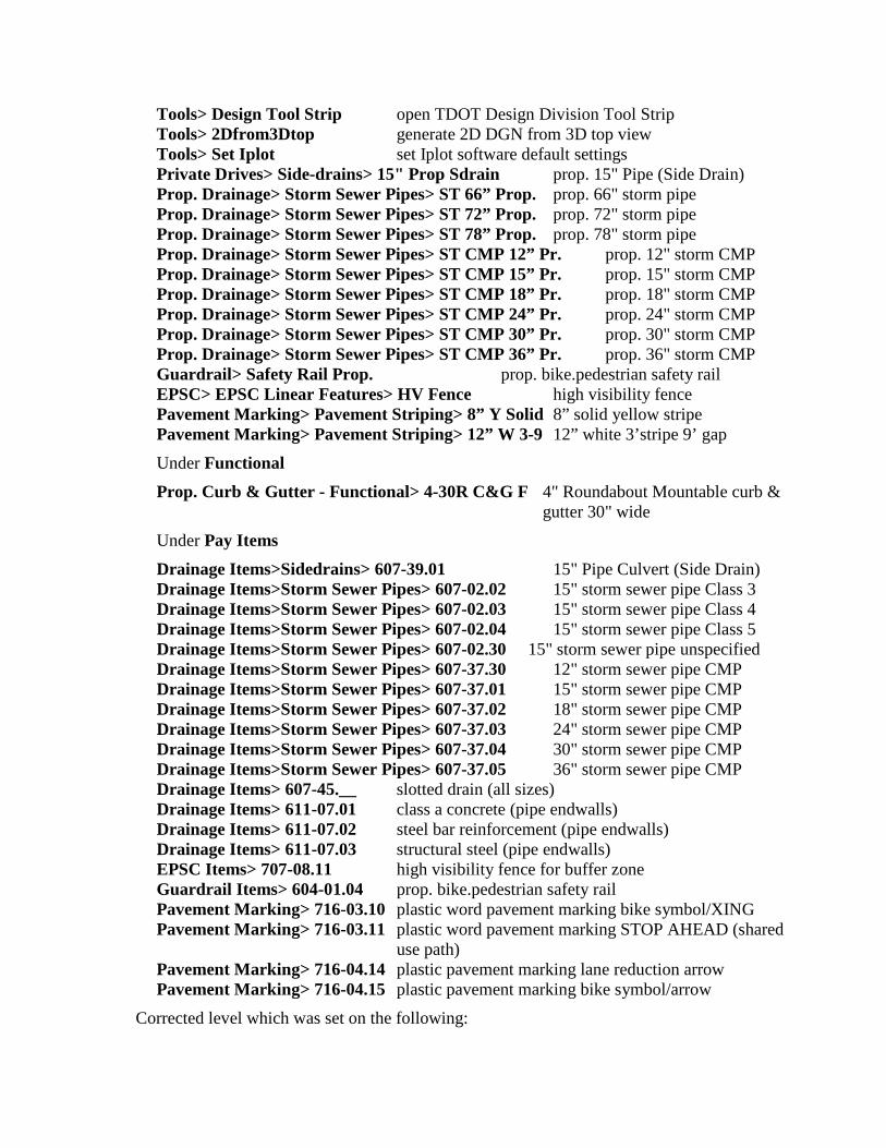
Tools> Design Tool Strip open TDOT Design Division Tool Strip Tools> 2Dfrom3Dtop generate 2D DGN from 3D top view Tools> Set Iplot set Iplot software default settings Private Drives> Side-drains> 15" Prop Sdrain prop. 15" Pipe (Side Drain) Prop. Drainage> Storm Sewer Pipes> ST 66” Prop. prop. 66" storm pipe Prop. Drainage> Storm Sewer Pipes> ST 72” Prop. prop. 72" storm pipe Prop. Drainage> Storm Sewer Pipes> ST 78” Prop. prop. 78" storm pipe Prop. Drainage> Storm Sewer Pipes> ST CMP 12” Pr. prop. 12" storm CMP Prop. Drainage> Storm Sewer Pipes> ST CMP 15” Pr. prop. 15" storm CMP Prop. Drainage> Storm Sewer Pipes> ST CMP 18” Pr. prop. 18" storm CMP Prop. Drainage> Storm Sewer Pipes> ST CMP 24” Pr. prop. 24" storm CMP Prop. Drainage> Storm Sewer Pipes> ST CMP 30” Pr. prop. 30" storm CMP Prop. Drainage> Storm Sewer Pipes> ST CMP 36” Pr. prop. 36" storm CMP Guardrail> Safety Rail Prop. prop. bike.pedestrian safety rail EPSC> EPSC Linear Features> HV Fence high visibility fence Pavement Marking> Pavement Striping> 8” Y Solid 8” solid yellow stripe Pavement Marking> Pavement Striping> 12” W 3-9 12” white 3’stripe 9’ gap Under Functional Prop. Curb & Gutter - Functional> 4-30R C&G F 4" Roundabout Mountable curb &
gutter 30" wide Under Pay Items
Drainage Items>Sidedrains> 607-39.01 15" Pipe Culvert (Side Drain) Drainage Items>Storm Sewer Pipes> 607-02.02 15" storm sewer pipe Class 3 Drainage Items>Storm Sewer Pipes> 607-02.03 15" storm sewer pipe Class 4 Drainage Items>Storm Sewer Pipes> 607-02.04 15" storm sewer pipe Class 5 Drainage Items>Storm Sewer Pipes> 607-02.30 15" storm sewer pipe unspecified Drainage Items>Storm Sewer Pipes> 607-37.30 12" storm sewer pipe CMP Drainage Items>Storm Sewer Pipes> 607-37.01 15" storm sewer pipe CMP Drainage Items>Storm Sewer Pipes> 607-37.02 18" storm sewer pipe CMP Drainage Items>Storm Sewer Pipes> 607-37.03 24" storm sewer pipe CMP Drainage Items>Storm Sewer Pipes> 607-37.04 30" storm sewer pipe CMP Drainage Items>Storm Sewer Pipes> 607-37.05 36" storm sewer pipe CMP Drainage Items> 607-45.__ slotted drain (all sizes) Drainage Items> 611-07.01 class a concrete (pipe endwalls) Drainage Items> 611-07.02 steel bar reinforcement (pipe endwalls) Drainage Items> 611-07.03 structural steel (pipe endwalls) EPSC Items> 707-08.11 high visibility fence for buffer zone Guardrail Items> 604-01.04 prop. bike.pedestrian safety rail Pavement Marking> 716-03.10 plastic word pavement marking bike symbol/XING Pavement Marking> 716-03.11 plastic word pavement marking STOP AHEAD (shared
use path) Pavement Marking> 716-04.14 plastic pavement marking lane reduction arrow Pavement Marking> 716-04.15 plastic pavement marking bike symbol/arrow
Corrected level which was set on the following:
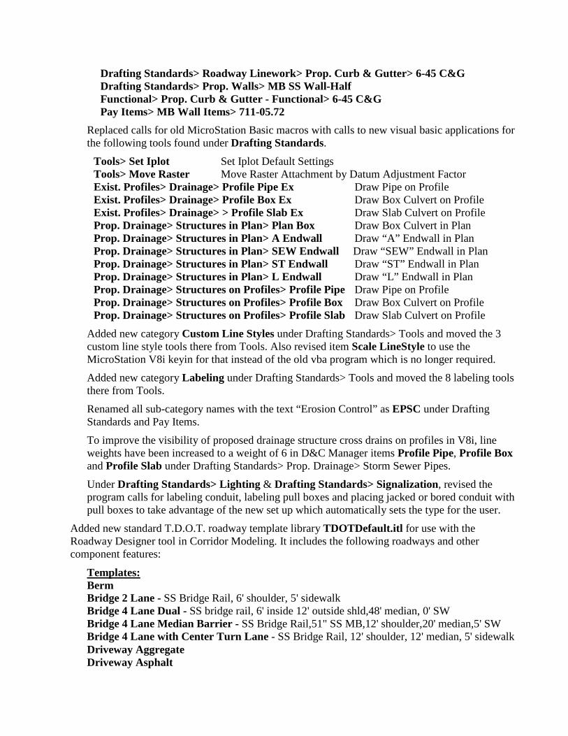
Drafting Standards> Roadway Linework> Prop. Curb & Gutter> 6-45 C&G Drafting Standards> Prop. Walls> MB SS Wall-Half Functional> Prop. Curb & Gutter - Functional> 6-45 C&G Pay Items> MB Wall Items> 711-05.72
Replaced calls for old MicroStation Basic macros with calls to new visual basic applications for the following tools found under Drafting Standards.
Tools> Set Iplot Set Iplot Default Settings Tools> Move Raster Move Raster Attachment by Datum Adjustment Factor Exist. Profiles> Drainage> Profile Pipe Ex Draw Pipe on Profile Exist. Profiles> Drainage> Profile Box Ex Draw Box Culvert on Profile Exist. Profiles> Drainage> > Profile Slab Ex Draw Slab Culvert on Profile Prop. Drainage> Structures in Plan> Plan Box Draw Box Culvert in Plan Prop. Drainage> Structures in Plan> A Endwall Draw “A” Endwall in Plan Prop. Drainage> Structures in Plan> SEW Endwall Draw “SEW” Endwall in Plan Prop. Drainage> Structures in Plan> ST Endwall Draw “ST” Endwall in Plan Prop. Drainage> Structures in Plan> L Endwall Draw “L” Endwall in Plan Prop. Drainage> Structures on Profiles> Profile Pipe Draw Pipe on Profile Prop. Drainage> Structures on Profiles> Profile Box Draw Box Culvert on Profile Prop. Drainage> Structures on Profiles> Profile Slab Draw Slab Culvert on Profile
Added new category Custom Line Styles under Drafting Standards> Tools and moved the 3 custom line style tools there from Tools. Also revised item Scale LineStyle to use the MicroStation V8i keyin for that instead of the old vba program which is no longer required.
Added new category Labeling under Drafting Standards> Tools and moved the 8 labeling tools there from Tools.
Renamed all sub-category names with the text “Erosion Control” as EPSC under Drafting Standards and Pay Items.
To improve the visibility of proposed drainage structure cross drains on profiles in V8i, line weights have been increased to a weight of 6 in D&C Manager items Profile Pipe, Profile Box and Profile Slab under Drafting Standards> Prop. Drainage> Storm Sewer Pipes.
Under Drafting Standards> Lighting & Drafting Standards> Signalization, revised the program calls for labeling conduit, labeling pull boxes and placing jacked or bored conduit with pull boxes to take advantage of the new set up which automatically sets the type for the user.
Added new standard T.D.O.T. roadway template library TDOTDefault.itl for use with the Roadway Designer tool in Corridor Modeling. It includes the following roadways and other component features:
Templates: Berm Bridge 2 Lane - SS Bridge Rail, 6' shoulder, 5' sidewalk Bridge 4 Lane Dual - SS bridge rail, 6' inside 12' outside shld,48' median, 0' SW Bridge 4 Lane Median Barrier - SS Bridge Rail,51" SS MB,12' shoulder,20' median,5' SW Bridge 4 Lane with Center Turn Lane - SS Bridge Rail, 12' shoulder, 12' median, 5' sidewalk Driveway Aggregate Driveway Asphalt
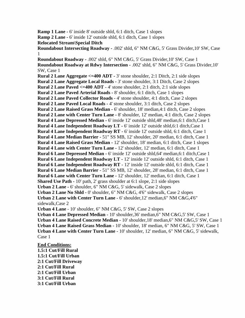
Ramp 1 Lane - 6' inside 8' outside shld, 6:1 ditch, Case 1 slopes Ramp 2 Lane - 6' inside 12' outside shld, 6:1 ditch, Case 1 slopes Relocated Stream\Special Ditch Roundabout Intersecting Roadway - .002' shld, 6" NM C&G, 5' Grass Divider,10' SW, Case 1 Roundabout Roadway - .002' shld, 6" NM C&G, 5' Grass Divider,10' SW, Case 1 Roundabout Roadway at Rdwy Intersection - .002' shld, 6" NM C&G, 5' Grass Divider,10' SW, Case 1 Rural 2 Lane Aggregate <=400 ADT - 3' stone shoulder, 2:1 Ditch, 2:1 side slopes Rural 2 Lane Aggregate Local Roads - 3' stone shoulder, 3:1 Ditch, Case 2 slopes Rural 2 Lane Paved <=400 ADT - 4' stone shoulder, 2:1 ditch, 2:1 side slopes Rural 2 Lane Paved Arterial Roads - 8' shoulder, 6:1 ditch, Case 1 slopes Rural 2 Lane Paved Collector Roads - 4' stone shoulder, 4:1 ditch, Case 2 slopes Rural 2 Lane Paved Local Roads - 4' stone shoulder, 3:1 ditch, Case 2 slopes Rural 2 Lane Raised Grass Median - 6' shoulder, 18' median,4:1 ditch, Case 2 slopes Rural 2 Lane with Center Turn Lane - 8' shoulder, 12' median, 4:1 ditch, Case 2 slopes Rural 4 Lane Depressed Median - 6' inside 12' outside shld,48' median,6:1 ditch,Case 1 Rural 4 Lane Independent Roadway LT - 6' inside 12' outside shld,6:1 ditch,Case 1 Rural 4 Lane Independent Roadway RT - 6' inside 12' outside shld, 6:1 ditch, Case 1 Rural 4 Lane Median Barrier - 51" SS MB, 12' shoulder, 20' median, 6:1 ditch, Case 1 Rural 4 Lane Raised Grass Median - 12' shoulder, 18' median, 6:1 ditch, Case 1 slopes Rural 4 Lane with Center Turn Lane - 12' shoulder, 12' median, 6:1 ditch, Case 1 Rural 6 Lane Depressed Median - 6' inside 12' outside shld,64' median,6:1 ditch,Case 1 Rural 6 Lane Independent Roadway LT - 12' inside 12' outside shld, 6:1 ditch, Case 1 Rural 6 Lane Independent Roadway RT - 12' inside 12' outside shld, 6:1 ditch, Case 1 Rural 6 Lane Median Barrier - 51" SS MB, 12' shoulder, 28' median, 6:1 ditch, Case 1 Rural 6 Lane with Center Turn Lane - 12' shoulder, 12' median, 6:1 ditch, Case 1 Shared Use Path - 10' path, 2' grass shoulder at 6:1 slope, 2:1 side slopes Urban 2 Lane - 6' shoulder, 6" NM C&G, 5' sidewalk, Case 2 slopes Urban 2 Lane No Shld - 0' shoulder, 6" NM C&G, 4'6" sidewalk, Case 2 slopes Urban 2 Lane with Center Turn Lane - 6' shoulder,12' median,6" NM C&G,4'6" sidewalk,Case 2 Urban 4 Lane - 10' shoulder, 6" NM C&G, 5' SW, Case 2 slopes Urban 4 Lane Depressed Median - 10' shoulder,36' median,6" NM C&G,5' SW, Case 1 Urban 4 Lane Raised Concrete Median - 10' shoulder,18' median,6" NM C&G,5' SW, Case 1 Urban 4 Lane Raised Grass Median - 10' shoulder, 18' median, 6" NM C&G, 5' SW, Case 1 Urban 4 Lane with Center Turn Lane - 10' shoulder, 12' median, 6" NM C&G, 5' sidewalk, Case 1
End Conditions: 1.5:1 Cut/Fill Rural 1.5:1 Cut/Fill Urban 2:1 Cut/Fill Driveway 2:1 Cut/Fill Rural 2:1 Cut/Fill Urban 3:1 Cut/Fill Rural 3:1 Cut/Fill Urban
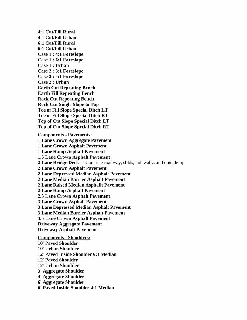
4:1 Cut/Fill Rural 4:1 Cut/Fill Urban 6:1 Cut/Fill Rural 6:1 Cut/Fill Urban Case 1 : 4:1 Foreslope Case 1 : 6:1 Foreslope Case 1 : Urban Case 2 : 3:1 Foreslope Case 2 : 4:1 Foreslope Case 2 : Urban Earth Cut Repeating Bench Earth Fill Repeating Bench Rock Cut Repeating Bench Rock Cut Single Slope to Top Toe of Fill Slope Special Ditch LT Toe of Fill Slope Special Ditch RT Top of Cut Slope Special Ditch LT Top of Cut Slope Special Ditch RT Components - Pavements: 1 Lane Crown Aggregate Pavement 1 Lane Crown Asphalt Pavement 1 Lane Ramp Asphalt Pavement 1.5 Lane Crown Asphalt Pavement 2 Lane Bridge Deck - Concrete roadway, shlds, sidewalks and outside lip 2 Lane Crown Asphalt Pavement 2 Lane Depressed Median Asphalt Pavement 2 Lane Median Barrier Asphalt Pavement 2 Lane Raised Median Asphallt Pavement 2 Lane Ramp Asphalt Pavement 2.5 Lane Crown Asphalt Pavement 3 Lane Crown Asphalt Pavement 3 Lane Depressed Median Asphalt Pavement 3 Lane Median Barrier Asphalt Pavement 3.5 Lane Crown Asphalt Pavement Driveway Aggregate Pavement Driveway Asphalt Pavement Components - Shoulders: 10' Paved Shoulder 10' Urban Shoulder 12' Paved Inside Shoulder 6:1 Median 12' Paved Shoulder 12' Urban Shoulder 3' Aggregate Shoulder 4' Aggregate Shoulder 6' Aggregate Shoulder 6' Paved Inside Shoulder 4:1 Median

6' Paved Inside Shoulder 6:1 Median 6' Paved Shoulder 6' Urban Shoulder 8' Aggregate Shoulder 8' Paved Shoulder 8' Urban Shoulder Components - Curb Gutter and Sidewalk: 6" M Type A - 30" Concrete Curb and Gutter 6" NM Type A - 30" Concrete Curb and Gutter 6-30 NM C&G - 30" Concrete Curb and Gutter 6-30 NM C&G with Subgrade - 30" Concrete Curb and Gutter Sidewalk Sidewalk Area Grass Divider Sidewalk Area Grass Only Sidewalk Area No Divider Components - Medians: Depressed Median 4:1 Depressed Median 6:1 Median Barrier 51" SS - 4 Lane - 10' offset to inside lane edge with subgrade Median Barrier 51" SS - 6 Lane - 14' offset to inside lane edge with subgrade Raised Median Concrete - 18' Wide, 2' inside shoulders, 6" M curbs with subgrade Raised Median Grass - 18' Wide, 2' inside shoulders, 6" M curbs with subgrade
Components - Walls and Barriers: Bridge Parapet Rail SS Median Barrier 51" SS Retaining Wall Cut Retaining wall Fill - Ties to edge of shoulder or back of curb
Added new data base file TDOT_Styles.ddb for use with our roadway template library & Roadway Designer. It includes the following categories and items used by our templates:
Centerline Centerline Pavement Aggregate Asphalt Concrete Pavement Inside Edge Pavement Outside Edge Wedging Shoulder Shoulder Shoulder Inside Edge Shoulder Pavement Edge Shoulder Inside Pavement Edge Curb and Gutter
Curb Curb Top Curb Back Truck Apron Pavers Sidewalk Sidewalk Medians Median Ditch End Conditions Grass RipRap Ditch Foreslope Ditch Backslope Ditch Toe of Fill Ditch Top of Cut Ditch Bench Cut Fill Walls Barrier Barrier Face Barrier Top Wall Wall Face Wall Top Wall Bottom Miscellaneous Uncontrolled
In plan sheet set up library, TDOT.psl, corrected level for labeling profile elevations at sides and stations at bottom to be DESIGN - PROFILE - Proposed Text.
Deleted vertical curve K value file tdot.kvl which was based on Roadway Design Division RD standards which are now obsolete.
In cross section sheet set up libraries, Culvert10scale.xssl, Culvert20scale.xssl, Roadway10scale.xssl, Roadway20scale.xssl, MetricCulvert100scale.xssl, MetricCulvert200scale.xssl, MetricRoadway100scale.xssl & MetricRoadway200scale.xssl, removed spaces from prefix and suffix fields for sheet labels which messed up text positioning in V8i.
In our TDOT Geopak Drainage Library (TDOTEnglish.dlb) Revised all concrete and plastic pipe link N values to be 0.013. Revised all aluminum ellipse & pipe arch link N values to be 0.024. Revised all box structures so that dimensions are given in the format we use, Width X Height. Revised available box structures to reflect standard T.D.O.T. box sizes.
Added descriptions to concrete box links for use in labels. Added pay item to 15” circular concrete link Added descriptions to circular aluminum pipe links for use in labels. Added pay items to 15” thru 36” circular aluminum pipe links Added the following new node items:
SD 12” Slotted Drain 12” Diameter, 20’ Length SD 15” Slotted Drain 15” Diameter, 20’ Length SD 18” Slotted Drain 18” Diameter, 20’ Length SD 24” Slotted Drain 24” Diameter, 20’ Length SD 30” Slotted Drain 30” Diameter, 20’ Length SD 36” Slotted Drain 36” Diameter, 20’ Length
In our Geopak Drainage project template DrainageProject.gdf, deleted empty drainage network named “tester”, updated preferences to use Windows 7 default folder locations and changed drainage area plan view graphics to place on levels SURVEY - DRAINAGE - Area Shapes & SURVEY - DRAINAGE - Area Shapes Text at color 4 & a weight of 2. Added new default drainage project preference file, TDOTdrainageprefs.dpf, which can be used to reset drainage project preferences back to default values in current drainage projects.
Deleted total non-specific profile display preference file TDOTStormSewerProfiles.ppf since current use of specific versions for Design (TDOTStormSewerProfiles-Design.ppf) and Plan (TDOTStormSewerProfiles-Plan.ppf) displays fill our needs and can be adjusted as desired.
Rebuilt and renamed culvert drainage report format file TDOTculvertsFULL.drf with all drainage data items.
Deleted abbreviated drainage report format files TDOTlinks.drf & TDOTnodes.drf which are not used by our auto build Excel tabulation programs.
In Plan Labeler style file tdotdef_plan.lsf, revised or corrected the following items. Most of these were adjustments to the text justification which in V8i effects the location of labels placed with a horizontal line delimiter.
Under Survey Labels
Survey Control> Horiz Cntrl Pt replaced corrupted point # insert Survey Control> Vert Cntrl Pt replaced corrupted point # insert Pres. ROW> Arc Length Flag fixed label text justification Pres. ROW> Bea/Dis Flag fixed label text justification Pres. ROW> Distance Flag fixed label text justification Pres. ROW> Offset Flag fixed label text justification Pres. ROW> Radius Flag fixed label text justification Pres. PLs> Arc Length Flag fixed label text justification Pres. PLs> Bea/Dis Flag fixed label text justification Pres. PLs > Distance Flag fixed label text justification Pres. PLs > Offset Flag fixed label text justification Pres. PLs > Radius Flag fixed label text justification
Pres. Esmt.> Arc Length Flag fixed label text justification Pres. Esmt.> Bea/Dis Flag fixed label text justification Pres. Esmt.> Distance Flag fixed label text justification Pres. Esmt.> Offset Flag fixed label text justification Pres. Esmt.> Radius Flag fixed label text justification
Under Design Labels
Centerline> Intersection Bot fixed label text justification Drainage> Beg Br fixed label text justification Drainage> Beg Box Br fixed label text justification Drainage> End Br fixed label text justification Drainage> End Box Br fixed label text justification Private Drives> BusEnt Urban fixed label text justification Private Drives> PvtDr L O C fixed label text justification Private Drives> PvtDr Urban fixed label text justification Roads> Limit of Const fixed label text justification Roads> Limit of Paving fixed label text justification Roads> Limit of Resurf fixed label text justification
In Profile Labeler style file tdotdef_prof.lsf, renamed first Highwater label as Normal Water El. Under Survey Labels> Exist. Drainage.
In Drainage Labeler style file tdotdef_drainage.lsf, fixed broken Drainage Area label style, added new style Outfall DA for labeling outfall drainage areas on EPSC plans and added new style Outlet Elev for labeling storm drainage endwall outlets..
• TDOTSMDFeatures.exe Revised SMD feature ROCKW (rock wall) to use the new line style ROCK WALL FACE which is set up at the face of the rock wall symbology so field personnel can easily gather points at the face of the wall without a need for post processing in the office to position the wall correctly when wall center points couldn’t be gathered. Field Points should be gathered from left to right so that wall will appear correctly when visualized. WARNING: Care should be taken if the need arises to re-visualize data gathered prior to this change since older rock walls set up on the wall centerline would be shifted with this new set up. Re-visualizing will replace the old line style ROCK WALL with the new one. If this happens, simply change the line style back to ROCK WALL.
• Criteria.exe In all typical roadway section Write documents, *.wri, removed paragraph describing the error message which came up in the past concerning application on shapeless roadways. This error message box is now disabled by default in our set up of Geopak V8i.
Added the following new criteria programs to handle special situations:
Case2slopesToWall.x Case II Variable Slopes which extends to a “Wall” which has been created in a previous run
MedianRaisedGrass8to1NoCurb.x Raised Grass Median w/8:1 slope & w/o curbs
PvtDriveProfileUrbanTypeACurb.x Private Drive Profiles - Urban Roadways w/type A detached curb
SlopeButtress1.5.x Fill Slope Buttress - 1.5.1 buttress slope based on top of buttress elevation
SubgradeIntercept.x Wedge Subgrade Closure at Ditch Slope
In Case1slopesC&G.x & Case1slopesC&Gmetric.x, added missing program code to set special ditch text labels for special ditches based along roadway prior to normal slope tie.
In MultiLaneFreewayMBShlds.x, revised how the bottom of 51 inch single slope median barrier is formed to match stipulations of standard roadway drawing S-SSMB-9 and added warning text if height of wall exceeds maximum height. Also revised how subgrade is formed under walls that are greater than standard height to maintain stone base beneath wall.
In RoundaboutTruckApron.x, revised code to look for curb around central island to handle truck aprons with variable widths.
• 3PC.exe Updated program SlopeDrain_Computation.x for V8i with minor changes and clean up.
Updated program Tree_Computation.x for V8i with minor changes and clean up.
Added new programs PipeEndwall_Computation.x & PipeEndwall_ComputationMetric.x which read a D&C Manager set & then pulls the quantities for concrete, reinforcing steel and structural steel from pipe endwall graphics that had that data written to them as adhoc information when they were created. It then reports the quantities back to D&C Manager. This is set up specifically for preliminary quantity estimates.
Added new programs SlottedDrains_Computation.x & SlottedDrains_ComputationMetric.x reads a D&C Manager set & then counts the slotted drain cells and reports the linear feet quantity back to D&C Manager. Cells are defined in a 20 foot length so each cell counts as 20 linear feet of that size slotted drain.
In pavement striping quantity programs Striping_Paint_Computation.x, Striping_Paint_ComputationMetric.x, Striping_Thermo_Flatline_Computation.x, Striping_Thermo_Flatline_ComputationMetric.x, Striping_Thermo_Spray40_Computation.x, Striping_Thermo_Spray40_ComputationMetric.x, Striping_Thermo_Spray60_Computation.x & Striping_Thermo_Spray60_ComputationMetric.x, added code to handle new 8” solid yellow stripes.
In pavement striping quantity programs Striping_Paint_Computation.x, Striping_Paint_ComputationMetric.x, Striping_Thermo_Flatline_Computation.x, Striping_Thermo_Flatline_ComputationMetric.x, Striping_Thermo_Spray60_Computation.x & Striping_Thermo_Spray60_ComputationMetric.x, added code to handle new 12” white stripes (3’ dash 9’ gap).

Office
All templates converted and upgraded to full Office 2010 compatibility. Templates have been renamed with spaces as needed for clarity.
• DDOCS.exe All templates with letter heads were updated to new required format with commissioner and governor listed below. Text entry fields are provided in letterhead for application for each Design office.
All templates revised as needed to reflect current requirements as shown in T.D.O.T. Roadway Design Division Roadway Design Guidelines and its associated instructional bulletins. Word templates for plans turn in have been revised to include Project Manager as an option in the CC list at the bottom as indicated in Design Guidelines IB 12-16.
In Excel template Additional Survey Request Form.xltm the following changes were made:
Revised file Save and Save As functions to maintain Office 2010 macro enabled file type. Adjusted drop down options. Updated name lists on hidden worksheet ADDRESS. Revised Survey personel to be new generic email address for regional offices and headquarters on worksheet REQUEST and on hidden worksheet ADDRESS.
Added new Office 2010 Word template, Request For Review Of Pavement Design.dotx, which should be used if your pavement design is over 2 years old at the time of the construction field review as shown in Roadway Design Guidelines IB 12-14.
Added a new Office 2010 Word template, Green Sheet Certification Letter.dotx, which is used on projects that include environmental commitments in the Green Sheet Certification Process as shown in Roadway Design Guidelines IB 13-07.
Added approved blank letterhead templates for various Roadway Design Division offices.
• 2ndSheets.exe In Excel quantities templates Bridge Quantities.xltm, Estimated Roadway Quantities.xltm and Maintenance Quantities.xltm, the following changes were made:
Revised file Save and Save As functions to maintain Office 2010 macro enabled file type. Set macro buttons on worksheets to be static so they are not moved when columns or rows of estimate blocks are changed. Revised macro notes listed with buttons. Revised file paths in macros to reflect Windows 7 application.
In Excel quantities template Estimated Roadway Quantities.xltm the following additional changes were made:
Revised filenames of auto-build templates referenced in vba module AutoBuildCalls and added single quote marks around filenames for application in Windows 7 Repositioned macro buttons to be evenly spaced.

In Excel template Convert Excel To V8.xltm, revised file paths in macros to reflect Windows 7 application.
Our Word template English Index & Std Dwgs.dotx has been updated. The standard drawing revision dates now are current up to those presented in Design Guidelines IB 13-1.
Our Word template English General Notes.dotx has been updated. The notes now include the new safety edge paving note as shown in Design Guidelines IB 12-14. & IB 12-17. Old RD series drawings have been removed or renamed as shown in Design Guidelines IB 12-12
Our Office 2010 Word templates for roadway standard drawings “To Be Printed With Plans” have been eliminated and that section has been removed from the Index & Standard Drawings templates to reflect Roadway Design Guidelines IB-12-10.
Deleted old Project Data template ProjectData.xlt which had been provided in the past for addition to old quantities files that did not have that worksheet included.
• EnglishTab.exe & MetricTab.exe Added new Excel templates Slab Bridge.xltx & Slab Culvert.xltx.
Our drainage Excel templates: Cross Drain Freeways.xltx, Cross Drain Arterials WO Full Access Control.xltx, Cross Drain Collectors.xltx, Cross Drain Local Roads.xltx, Side Drain.xltx and Median Drains.xltx, have been updated to reflect changes from the update of the T.D.O.T. Drainage Manual which was recently posted to the internet. These changes include the revised fill height criteria as well as the new SRTRP pipe type alternate.
In Excel template Guardrail Tab Builder.xltm, revised file paths in macros to reflect Windows 7 application.
Updated Excel template Storm Drainage Structure Tab Builder.xltm to handle slotted drain structures when building tabulations. This included building main header, structure dimensions, item tabulation header and quantity entered since these are measured in linear feet with 20 foot segments for each structure placed. Also revised file paths in macros to reflect Windows 7 application.
Updated Excel template Storm Drainage Pipe Tab Builder.xltm to handle CMP pipes which are used with slotted drain structures. Also revised file paths in macros to reflect Windows 7 application.
• English Survey & Design Manday Form version 2.24.xlsm Updated T.D.O.T. logo shown in document worksheets, deleted linked working documents and updated version to 2.24.
• ROWAcqTable.exe In Excel template ROWAcqTable.xltm, revised file Save and Save As functions to maintain Office 2010 macro enabled file type.
Aerial Survey
• ASdata.exe Revised the default download location to be C:\Users\Public\MicroStation Standards\data.
• ASseed.exe Updated seed file with latest levels, level filters and text styles. Also revised the default download location to be C:\Users\Public\MicroStation Standards\seed.
• AStdotcfg.exe Removed this download file since Aerial Survey personnel now use the default version provided under the MicroStation downloads, TDOTcfg.exe.
• AScamera.exe Removed this download file since Aerial Survey personnel no longer use this analog camera set up.
Iplot
• DesignScripts.exe In design script files COLORE.FUL, COLORE.HAF, IRP336.FUL, IRP336.HAF, IRP336.HLF, IRP336.STD, Irp336c.hlf, PDF.FUL, PDF.HAF, PDFColor.FUL, PHCOLORE.FUL, transBlkCOLORE.FUL, transBlkCOLORE.HAF, transBlkPHCOLORE.FUL, transBlkPHCOLORE.HAF, transCOLORE.FUL, transCOLORE.HAF, transPHCOLORE.FUL & transPHCOLORE.HAF, revised dot grid linear pattern code for profiles and cross sections to call line style dotted or half dotted by name from Iplot resource file style.slb. This was part of the solution to help correct dot grid plotting problems in sheet cells.
In translucent fill design script files transBlkCOLORE.FUL, transBlkCOLORE.HAF, transBlkPHCOLORE.FUL, transBlkPHCOLORE.HAF, transCOLORE.FUL, transCOLORE.HAF, transPHCOLORE.FUL & transPHCOLORE.HAF, revised priority for translucent fills to place below other graphics. Previous setting of 100 that worked well with translucent fills has been temporarily changed to 1 until translucent issues with InterPlot V8i are worked out.
In translucent fill design script files transCOLORE.FUL, transCOLORE.HAF, transPHCOLORE.FUL & transPHCOLORE.HAF, changed off white color used for remapping normal white from using color 64 to new color 70 which is closer to actual white..
In standard drawing design script files IRP336.STD, IRP336.HLF, Irp336c.hlf, IRP336M.STD, IRP336M.HLF & Irp336mc.hlf, revised code which makes all colors print black to ignore color 18 filled shapes and group holes used to show concrete on some standard drawings. Also reset priority of color 18 element area fills to 1 to prevent covering up of other line work.
• IplotResrc.exe Revised line style dotted to match requirements for 0.10” dot grid used on full size profile & cross section sheets and added line style half dotted to line styles defined in style.slb. This was part of the solution to help correct dot grid plotting problems in sheet cells.
• IplotCFG.exe Rebuilt for use on Windows 7 operating system with TDOT standards loaded under C:\Users\Public.
• IpCFG.exe Rebuilt for use on Windows 7 operating system with TDOT standards loaded under C:\Users\Public.
• Settings.exe Added new settings files Pdf254EnglishFul.set and Pdf254MetricFul.set to facilitate the production of full size PDF documents from older project plan sheets which used MicroStation J sheet borders with only color 254 plot shapes. These settings should not be used for plans created after January 2006.
AutoTrack
• TDOTDesignVehicleLibrary.exe Re-built design vehicle library US_Tennessee.ATL, for use in Tennessee from new AutoTrack 10.05 base set up which now includes design vehicle definitions from the 2011 AASHTO green book.
Documentation
• CADDV8.pdf See the Manual Revisions at the end of document for detailed description of changes which reflect this CADD update as well as other informational changes.
• TDOT Roadway Design Division Programs.pdf Not yet updated for V8i.
• MicroStation V8 Manual.pdf Not yet updated for V8i.
• TDOT GEOPAK Road Course Guide.pdf The course guide has been completely reviewed and updated for application of GEOPAK V8i (SELECT Series 2), version 08.11.07.566. This includes multiple instances of tool locations in the new GEOPAK Civil Workflows task group within the MicroStation task navigation rather than the old GEOPAK Road Tools tool frame. We have also used color images for dialog captures and other views to more accurately illustrate how things look in MicroStation & Geopak V8i.
The following revision notes reflect actual changes in work flow and additional information that has been added but does not include all of the general changes that have been done.
Introduction Updated the standard GEOPAK run types listed under the GEOPAK Road Project File Structure to reflect that 3D model runs now use the extension .000 instead of .010 which is no longer used and the elimination of extension .00f for Reports & Cross Section Quantities since they no longer use runs for their functionality.
Exercise 2 Replaced the use of GEOPAK Road Tools tool frame with the new Civil Workflows task set up in the MicroStation V8i task navigation for Project Manager access in steps 2 and 3 on pages 2-1 and 2-2.
Exercise 4 Changed the standard folder specified for TDOT Roadway Design Division GEOPAK standards in step 5 on page 4-19. A new listing of Turning Path standard files for T.D.O.T. was also added to that exercise step.
Replaced the use of GEOPAK Road Tools with the new Road Tools task group in the MicroStation V8i task navigation for the GEOPAK Text Editor access in step 4 on page 4-25.
Exercise 5 Added reference to access of the Design & Computation Manager through the MicroStation Main task group when GEOPAK Civil Workflows are active in step 2 on page 5-1.
Exercise 6 Added reference to access of the Design & Computation Manager through the MicroStation Main task group when GEOPAK Civil Workflows are active in step 2 on page 6-5.
Exercise 7 Revised step 5 on page 7-2 to reflect that standard K value file tdot01.kvl is loaded by default. In the previous version it was necessary for the user to load this file. Also changed the standard folder specified for TDOT Roadway Design Division GEOPAK standards in that exercise step and removed the reference to the old RD standards.
Exercise 8 Replaced the use of GEOPAK Road Tools with the new Road Tools task group in the MicroStation V8i task navigation for the GEOPAK Cross Section Navigator access in step 1 on page 8-6.
Exercise 9 Deleted old step 7 on page 9-5. This step concerned a warning message generated in the previous software version concerning shapeless runs which is now suppressed by default since our set ups are valid for shaped or shapeless proposed cross section runs. A reference to that warning message in old step 8 (new step 7) was removed also.
Added a new note in step 11 on page 9-8 referring to a minor issue where sometimes the criteria file descriptions are not shown.
In step 13 on page 9-9, a note and image concerning the user being prompted to overwrite criteria files placed in the project folder previously was removed. This warning message is now suppressed by default. Also expanded the note concerning later updates to project criteria files to include reference to the T.D.O.T. Roadway Design Division tool, Update Project XS Criteria Files to perform that task.
In step 2 on page 9-16, added a new specification to click on option Pavement Shapes under Plot Parameters. This new Plot Parameter option is now necessary for superelevation shapes to be plotted on the cross sections when they are used.
In step 2 on page 9-17, expanded the description of the options on the Run Proposed Cross Sections dialog to include Criteria Viewer and Disable View Update. The last one is a new option in the software which suppresses screen graphics updates to speed up proposed cross section processing.
Exercise 10 Replaced the use of GEOPAK Road Tools with the MicroStation Main task group when GEOPAK Civil Workflows are active for the Active Chain Control access in step 2 on page 10-4.
Replaced the use of GEOPAK Road Tools with the new Road Tools task group in the MicroStation V8i task navigation for the GEOPAK Cross Section Navigator access in step 1 on page 10-8.
Changed the D&C Manager location specified for access to Label Station/Offset tool in step 1 on page 10-9.
Added new section, 10e. Tracking with the DP Profile Station Elevation Tool, on page 10-10.
Exercise 12 Added reference to New Element Only option which is available on D&C Manager’s secondary dialog when running in expanded mode in step 5 on page 12-2.
Replaced the reference to GEOPAK Road Tools with the new Plans Prep & Quantities task group in the MicroStation V8i task navigation for the Draw Transition tool access in step 6 on page 12-3.
Re-wrote step 7 on page 12-9 to reflect MicroStation V8i changes in the way its Change Direction tool now functions.
Added reference to the new Design Division Tool Strip for access to custom line style manipulation tools in step 8 on page 12-10.
Exercise 13 Deleted old step 3 on page 13-1. This step concerned clicking OK on the initial COGO sub-dialog which used to come up but does not do so if Project Manager is running.
Removed notes on page 13-9 concerning Manual Definition of Lanes which were not really needed since this topic is covered in step 6 on page 13-12.
Expanded Notes on Replacing Superelevation Shapes after step 11 on page 13-18 to include reasons shapes might need to be replaced as well as recommendations to avoid that necessity when profile adjustments are required.
Replaced the reference to GEOPAK Road Tools Cross Section tool box with the new Road Tools task group in the MicroStation V8i task navigation for the Superelevation Shape Manager Tools access in the notes on page 13-19.
Added new step 4 on page 13-21 describing the use of the Dynamic function of the Shape Analyst tool.
Re-organized steps and notes for the Shape Properties tool on pages 13-22 and 13-23 for better clarity.
Added new notes for use of the Autoshape Builder tool on page 13-24.
Exercise 14 Deleted old step 11 on page 14-7. This step included a note and image about the user being prompted to overwrite criteria files placed in the project folder previously. This warning message is now suppressed by default.
Replaced the use of GEOPAK Road Tools with the new Road Tools task group in the MicroStation V8i task navigation for the GEOPAK Text Editor access in step 1 on page 4-12.
Added new note concerning replacement of variable criteria files after step 11 on page 14-18.
Re-organized steps 4 & 5 on page 14-19 concerning review items after the final proposed cross section run for better clarity.
Exercise 15 Added note concerning new Disable View Update option for earthwork processing runs in step 8 on page 15-5.
Added new step 9 on page 15-6 which discusses the need to skip cross sections during earthwork processing and when it should not be done with reference to the Skip Areas & Ignore Areas section of the chapter.
Renamed Skip Areas section on pages 15-13 and 15-14 to be Skip Areas & Ignore Areas since this section illustrates the use of both of those earthwork control set ups.
Exercise 16 Changed the standard folder specified for TDOT Roadway Design Division GEOPAK standards in step 3 on page 16-2.
Added additional notes concerning more than 2 earthwork data items on cross section sheets with guidance on set up of these in step 10 on page 16-6.
Revised step 18 on page 16-11 to include instruction to set Project Data Location to Line #1 since the default is for Line #2.
Exercise 17 Added new note on alternate access for XS Reports & Quantities from the MicroStation menu bar or the new Road Tools task group in the MicroStation V8i task navigation in step 2 on page 17-1.
Exercise 18 Replaced the reference to GEOPAK Road Tools with the new Plans Prep & Quantities task group in the MicroStation V8i task navigation for the DP/Station Offset tool access in step 3 on page 18-1.
Replaced the reference to GEOPAK Road Tools with the new Plans Prep & Quantities task group in the MicroStation V8i task navigation for the Plan View Labeler tool access in step 3 on page 18-1.

Added note to step 6 on page 18-4 to provide guidance on typing around smart data items in Geopak label set ups.
Expanded step 14 on page 18-9 to include an alternate angle setting for the label to be 90 degrees to the centerline.
Replaced the references to GEOPAK Road Tools for other GEOPAK Labelers with the new task group locations using Civil Workflows in the MicroStation V8i task navigation on page 18-10.
Exercise 19 Changed the standard folder specified for TDOT Roadway Design Division GEOPAK standards in step 3 on page 19-3.
Revised step 3 on page 19-10 to specify the use of the Edit Sheet Number dialog to Append Alpha Suffix on plan sheet numbers such as in sheet “4A”.
Revised the Sheet Name Prefix section of step 1 on page 19-11 to specify the use of 4 asterisks in square brackets instead of 3 as specified in the past and removed the instructions to insert the suffix letter at this time which is now done previously in the Edit Sheet Number part of the workflow to generate plan sheets. The sheet suffix letter(s) can no longer be added in Clip Sheets using Sheet Name Prefix. Also revised notes at the top of page 19-12 concerning controlling sheet names with the Clip Sheet tool to reflect the changes in GEOPAK V8i.
Exercise 20 Re-wrote steps 3 through 6 on pages 20-5, 6 & 7 to reflect new visual basic cell placement controls which replaced the old MicroStation Cell Tools mdl function which is obsolete in MicroStation V8i.
Added a note after step 9 on page 20-11 describing the use of the guardrail quantities in Comp Book format with Microsoft Excel template Guardrail Tab Builder.xltm to build guardrail tabulation blocks.
Expanded notes in step 10 on page 20-12 to include a description of the use of the Collection area in D&C Manager when in Compute mode to allow the selection of various items from different categories under Pay Items.
Exercise 21 Replaced the reference to GEOPAK Road Tools with the new Classic Geometry task group in the MicroStation V8i task navigation for the Graphical COGO tools access in step 2 on page 21-1.
Revised step 9 on page 21-5 to include instruction to click on the check box to lock in the station value.
Changed the D&C Manager location specified for access to Text Styles Plus tool in step 1 on page 21-9.
Changed the D&C Manager location specified for access to Place Label with Leader tool in step 4 on page 21-11.
Exercise 22 Revised stations listed for guardrail pad points in step 3 on page 22-3 due to changes in Type 38 terminal pad requirements since last update to course guide.
Revised step 12 on page 22-7 with instruction to click on the Disable View Update option prior to processing proposed cross sections. The old instruction to turn views off to avoid view updates was removed since the new GEOPAK V88i function now handles this.
Replaced the reference to GEOPAK Road Tools with the new Road Tools task group in the MicroStation V8i task navigation for the XS Reports & Quantities tools access in step 14 on page 22-8.
Changed the standard folder specified for TDOT Roadway Design Division GEOPAK standards in step 19 on page 22-11. Also added a reference to the Edit Triangles tool for editing proposed surfaces.
Exercise 23 Replaced the reference to GEOPAK Road Tools with the new Classic Geometry task group in the MicroStation V8i task navigation for the Graphical COGO tools access in step 2 on page 23-1.
Replaced the reference to GEOPAK Road Tools with the new Road Tools task group in the MicroStation V8i task navigation for the Draw Profile tool access in step 1 on page 23-8.
Added a note concerning Void area symbology at the end of step 5 on page 23-10.
• TDOT Geopak Survey Training Manual.pdf Not yet updated for V8i.
• 2ndSheetsV8.pdf Updated for use with Office 2010 and MicroStation V8i on Windows 7 with new images and revised instructions for setting up Office 2010 for 2nd sheet production.
Revised template file lists to reflect new names on pages 17, 38 & 55,
Added new Excel templates Slab Bridge.xltx & Slab Culvert.xltx to template list on page 17.
• ROW Acq Tables.pdf Updated for use with Office 2010 and MicroStation V8i on Windows 7 with new images.
• InterPlot Organizer V8.pdf Updated for use with InterPlot Organizer and MicroStation V8i on Windows 7 with new images.
Added reference to accessing InterPlot Organizer from the new TDOT Design Division tool strip under the Plotting tool group in step 1 on page 1.
Added new settings files Pdf254English*Ful.set and Pdf254Metric*Ful.set to the InterPlot Organizer settings file list with notes concerning their use on pages 5 and 6.
Revised color plot queue names for headquarters and regional offices in list on page 11.
• Creating PDFs from DGNs.pdf Updated for use with InterPlot Organizer and MicroStation V8i with new images.
Revised PDF Sheet Sizes section on page 1 to reflect that all PDF plan sets posted to FileNet are now to be full size.
Added a paragraph in step 1 on page 2 explaining why PDF document sheet sizes are smaller than final printed sheets and must fall within the margins for correct printing results. Also added Document Sheet Sizes list with resulting dimensions.
Revised paragraph in step 1 on page 4 explaining why PDF254*.set settings files should not be used on plans developed after January 2006 due to printing issues in latest versions of Adobe Acrobat.
Added reference to new Export PDF icon on Interplot Organizer V8i tool bar in step 2 on page 8. Also added reference to new option to create individual PDF files for each sheet in the 2nd paragraph.
Added new reference section Creating PDF Portfolios for Final Construction Plans on page 11.
Revised section Creating PDF files using MicroStation Print with reference to accessing MicroStation Print from the new TDOT Design Division tool strip step 4 on page 13 and use of new sheet size PDF Regular Full in step 5 on the same page.
Replaced old MicroStation Batch Plotting section with new section PDF Plan Sets from MicroStation Print Organizer on pages 15-19.
Completely re-wrote section Printing PDF plan sheet files to reflect full size sheets in examples and to specifically describe the steps for proper printing from Adobe Acrobat versions 8, 9, 10 Standard and 10 Pro on pages 20-28.
• TDOT SURVEY SMD V8 FEATURE CODES.pdf Replaced T.D.O.T. logo on page 1.
Added revision note concerning replacement of line style for feature ROCKW (rock wall) which is now at the face of the walls on page 4.
• Proposed ROW.pdf Not yet updated for V8i.
• Pvt Dr Profiles.pdf Not yet updated for V8i.
• Line of Sight Investigations.pdf Not yet updated for V8i.
• State Plane Coordinates to Lat Long.pdf Updated for use with Geopak V8i with new images and new coordinate system names which should be used.
The Geodetic Coordinate Conversions dialog has changed significantly so although similar to past use, all steps have been re-written to reflect the changes.
• TDOT Geopak Drainage Nodes.pdf This document was updated to reflect the new minimum depth of structure values given in the updated standard drawings for storm drainage structures which were published in August 2012. Most minimum depths are now shallower except for LP structures which are now deeper. Several
rectangular sub-structures now allow larger pipe sizes in the wide wall. In the tables, this is represented by a W in the field specifying the minimum depth of cover for the given pipe size.
The notes at the beginning have been revised as well. The most significant stipulation is that values in the table for the minimum depth of cover of pipes represent the case of both inlet and outlet pipes being the same size. Whenever you only have an outlet pipe or the outlet pipe is larger, you must add the drop across bottom of structure value to the minimum depth of cover given in order to guarantee our minimum depth of structure values are maintained.
In November of 2012, a constructability issue came up which required an increase of 2” or 1” to the catch basin lid thickness and thereby the minimum depth that should be maintained. This did not affect low profile catch basins (32” X 32”) or larger ones (8’ diameter and greater) but does change most of the rest. The Design Standards group requested that CADD Support re-issue our documentation sooner in the hope that everyone can go ahead and update their designs as needed. The documentation has been updated with these new minimum depth of structure values as well as revised minimum depth of cover values which are used in Geopak Drainage to maintain minimum catch basin depths. All of the standard roadway drawings for these drainage structures were revised with the updated values and posted to the web January 28, 2013.
Added the following new Geopak Drainage node items with their design control data on page 6:
SD 12” Slotted Drain 12” Diameter, 20’ Length
SD 15” Slotted Drain 15” Diameter, 20’ Length
SD 18” Slotted Drain 18” Diameter, 20’ Length
SD 24” Slotted Drain 24” Diameter, 20’ Length
SD 30” Slotted Drain 30” Diameter, 20’ Length
SD 36” Slotted Drain 36” Diameter, 20’ Length.
• Land Use DGN Creation.pdf Not yet updated for V8i.
• TIN Surface from DEM.pdf Not yet updated for V8i.
• TDOT Roadway Design Division V8 Configurations for Consultant CADD Managers.pdf Updated for use with V8i.
• Converting TDOT Design Division V7 Project Files to V8.pdfUsing MrSID Image Files in MicroStation.pdf Deleted this obsolete documentation file.
• Title Sheets.pdf Not yet updated for V8i.
• Location Maps.pdf Not yet updated for V8i.
Tennessee Map Files for MicroStation
• County Map Index.pdf Updated to reflect changes in map files available from web page, Tennessee Map Files for MicroStation.
• Cheatham.exe Replaced graphics in DGN with new data from Mapping Division.
• Cumberland.exe Replaced missiing stream and lake boundary graphics in DGN.
• Obion.exe Replaced graphics in DGN with new data from Mapping Division. The CIT file has been replaced by graphics in the MicroStation DGN file.