REVISED UNIVERSAL SOIL LOSS EQUATION-Version 2
142
RUSLE2 REVISED UNIVERSAL SOIL LOSS EQUATION-Version 2 Predicting Soil Erosion By Water: A Guide to Conservation Planning
Transcript of REVISED UNIVERSAL SOIL LOSS EQUATION-Version 2

RUSLE2
REVISED UNIVERSAL SOIL LOSS EQUATION-Version 2
Predicting Soil Erosion By Water: A Guide to Conservation
Planning

UNIT 1
Course Objectives and Topics

OBJECTIVES
� Understand erosion processes
� Learn RUSLE2 and its software
� Learn field office applications of RUSLE2

UNIT 2
Overview of Erosion

OVERVIEW OF EROSION
� Definition of erosion � Erosion processes � Types of erosion � Why erosion is a concern � Uses of erosion prediction tools

EROSION
“Erosion is a process of detachment and transport of soil particles by erosive agents.” Ellison, 1944
� Erosive Agents- Raindrop impact- Overland flow surface runoff
from rainfall

DETACHMENT
� Removal of soil particles from soil surface
� Adds to the sediment load - Sediment load: Rate sediment is
transported downslope by runoff

DETACHMENT
Soil
Sediment Load Sediment Transport
Detachment

DEPOSITION
� Reduces the sediment load � Adds to the soil mass � Local deposition
- Surface roughness depressions - Row middles
� Remote deposition - Concave slope - Strips - Terraces

DEPOSITION
Soil
Sediment Load Sediment Transport
Deposition

TYPES OF EROSION
� Interrill and rill (sheet-rill) � Ephemeral gully � Permanent, incised (classical) gully � Stream channel � Mass movement � Geologic

DEFINITIONS
SOIL LOSS
SEDIMENT YIELD
RUSLE2 ESTIMATES TO HERE
Simple Uniform Slope

DEFINITIONSComplex Slope
Soil loss
Remote deposition
Sediment yield

DEFINITIONSComplex Slope
Soil loss
Remote deposition
Soil loss
Sediment yield

DEFINITIONS
Soil loss
Remote deposition Soil
loss
Sediment yield
Remote deposition
Soil loss
Strips

DEFINITIONS
Soil loss
Remote deposition
Soil loss
Sediment yield
Remote deposition
Soil loss
Remote deposition
Terraces

LOCAL DEPOSITION
Random Roughness
Ridges-Furrows

Credit for Deposition
Local Deposition
Full credit
Remote Deposition Partial credit Amount Location Spacing of terraces

SEDIMENT CHARACTERISTICS
� Particle Classes - Primary clay, primary silt, small aggregate, large
aggregate, primary sand � At Detachment
- Distribution of classes function of texture - Diameter of small and large aggregates function of
texture � After Deposition
- Sediment enriched in fines

EROSION IS A CONCERN
� Degrades soil resource - Reduces soil productivity - Reduces soil organic matter - Removes plant nutrients
� Causes downstream sedimentation � Produces sediment which is a pollutant � Produces sediment that carries
pollutants

WHERE EROSION CAN BE A PROBLEM
� Low residue crops � Conventional tillage � Rows up/down steep slopes � Low maintenance pasture � Disturbed land with little cover

EROSION PREDICTION AS A TOOL
� Guide management decisions � Evaluate impact of erosion � Inventory soil erosion � Conservation planning

EROSION PREDICTION AS A TOOL
� Concept: - Estimate erosion rate - Evaluate by ranking - Evaluate against quality criteria
� Tool: RUSLE2 � Quality Criteria: Soil loss tolerance

PLANNING VARIABLES
� Soil loss on eroding portions of hillslope � Detachment (sediment production) on
hillslope � Conservation planning soil loss for
hillslope � Ratio of segment soil loss to soil
tolerance adjusted for segment position � Sediment yield from hillslope/terraces

UNIT 3
Overview of RUSLE2

OVERVIEW OF RUSLE2(Revised Universal Soil Loss Equation-
Version 2) � Where RUSLE2 applies � Major factors affecting erosion � RUSLE2 factors � RUSLE2 background

Landscape Overland flow
Interrill
Rill
Ephemeral Gully (Concentrated flow)
Erosion Types
RUSLE2 Area
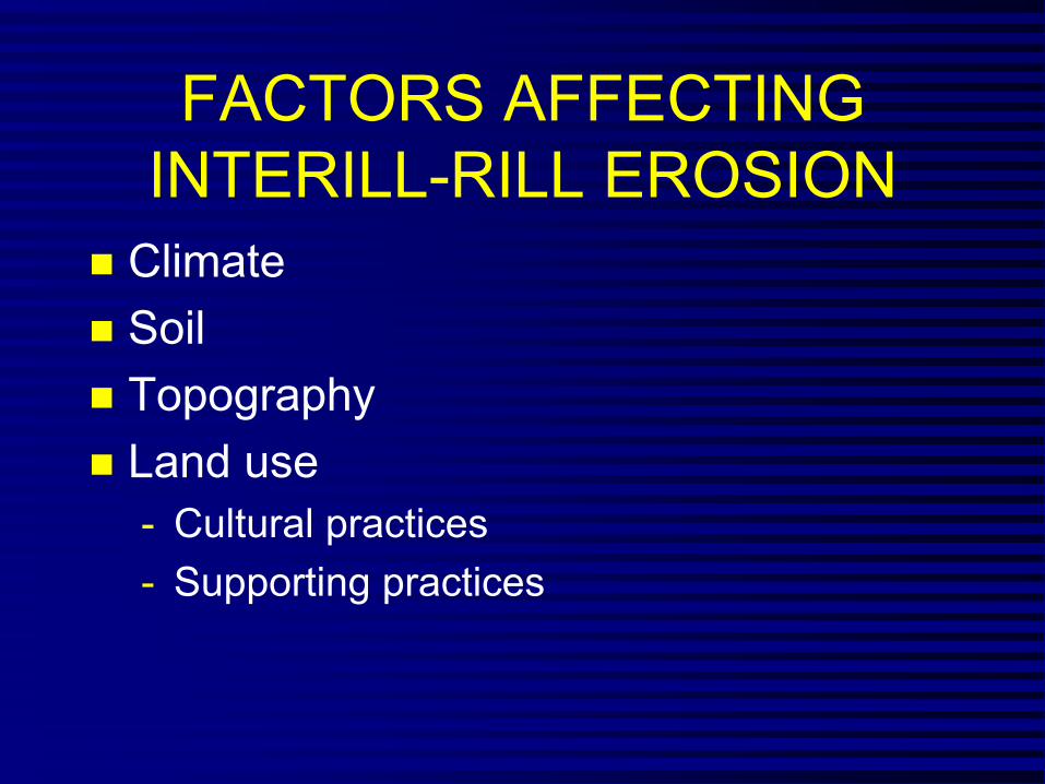
FACTORS AFFECTING INTERILL-RILL EROSION
� Climate � Soil � Topography � Land use
- Cultural practices
- Supporting practices

RUSLE2 FACTORSDaily Soil Loss
a = r k l s c pDaily Factors
r - Rainfall/Runoff s - Slope steepness k - Soil erodibility c - Cover-management l - Slope length p - Supporting practices
Average annual soil loss = sum of daily soil loss values
Different formulation from USLE and RUSLE1

RUSLE FACTORS(Sediment Production)
� Climate r � Soil k � Topography ls � Land Use and lscp Management

RUSLE FACTORS
A = f (erodibility, erosivity)
•
•
Erosivity – rklscp
Erodibility - klc

RUSLE FACTORS(Keep in mind that RUSLE2 operates on a daily basis)
Unit Plot Concept
a = rk lscp rk - Unit plot soil loss
(dimensions) lscp - Adjusts unit plot soil loss
(dimensionless)

Deposition
Transport capacity = sediment load
Sediment production less than transport capacity
Relation of deposition to transport capacity and sediment load on a complex slope
Hillslope Transport capacity
Sediment load
Deposition because sediment production exceeds transport capacity

Relationship of Deposition to Transport Capacity and Sediment Load for a Grass Strip
Dense
Erodible soil surface
Deposition region
Deposition ends where transport capacity = sediment load
Transport capacity
Sediment load
grass

How Deposition at a Grass Strip Affects Sediment Characteristics
Particle class Before (%) After (%) Primary clay 5 22 Primary silt 24 58 Small aggreg. 36 14 Large aggreg. 24 5 Primary sand 7 1
SDR = 0.2
Note how deposition enriches sediment in fines

RUSLE2 BACKGROUNDCombines empirical field data-process based equations
(natural runoff and rainfall simulator plots)
• Zingg’s equation (1940) • Smith and Whit’s equation (1947) • AH-282 (1965) • “Undisturbed land” (1975) • AH-537 (1978) • Disturbed forestland (1980) • RUSLE1 (1992) • AH703 (1997) • OSM Manual (mined, reclaimed land, construction sites)
(1998) • RUSLE2 (2001)

RUSLE2 APPLICATIONS� Cropland � Pastureland � Rangeland � Disturbed forest land � Construction sites � Surface mine reclamation � Military training lands � Parks � Waste disposal/landfills

SUMMARY
� Factors affecting erosion
� RUSLE2 factors
� RUSLE2 background

Unit 4
RUSLE2 Factors

RUSLE2 Factors(Keep in mind that factors are on a daily basis)
� r- erosivity factor � k- erodibility factor � l- slope length factor � s- slope steepness factor � c- cover-management factor � p- supporting practices factor

EROSIVITY
� Single storm - Energy x 30 minute intensity - Fundamentally product of rainfall amount x
intensity � Annual-sum of daily values � Average annual-average of annual values � Daily value=average annual x fraction that
occurs on a given day

EROSIVITY - RMeasure of erosivity of climate at a location
Las Vegas, NV 8Phoenix, AZ 22Denver, CO 40Syracuse, NY 80Minneapolis, MN 110Chicago, IL 140Richmond, VA 200St. Louis, MO 210Dallas, TX 275Birmingham, AL 350Charleston, SC 400New Orleans, LA 700

Erosivity Varies During Year1.2
1
0.8
1 25 49 73 97 121
145
169
193
217
241
265
289
313
337
361
CA SD MA TN
Day in Year
% E
I on
Day
0.6
0.4
0.2
0

10 yr EI
� Reflects locations where intense, erosive storms occur that have a greater than proportional share of theireffect on erosion - Effectiveness and failure of contouring - Effect of ponding on erosivity - Sediment transport capacity

Reduction by Ponding
� Significant water depth reduces erosivity of raindrop impact
� Function of: - 10 yr EI
- Landslope

SOIL ERODIBILITY - K
� Measure of soil erodibility under standard unit plot condition - 72.6 ft long, 9% steep, tilled continuous
fallow, up and down hill tillage � Independent of management � Major factors
- Texture, organic matter, structure, permeability

SOIL ERODIBILITY - K
� Effect of texture - clay (0.1 - 0.2) resistant to detachment - sand (0.05 - 0.15) easily detached, low
runoff, large, dense particles not easilytransported
- silt loam (0.25 - 0.35) moderately detachable, moderate to high runoff
- silt (0.4 -0.6) easily detached, high runoff,small, easily transported sediment

Time Variable K
� Varies during year � High when rainfall is high � Low when temperature is high � Very low below about 25 oF

Dai
ly S
oil E
rodi
bilit
y Va
lue
Time Variable K
0
1 25 49 73 97 121
145
169
193
217
241
265
289
313
337
361
CA SD MA TN
Base K value = 0.37
0.1
0.2
0.3
0.4
0.5
0.6
0.7
0.8
Day in Year

TOPOGRAPHY
� Overland flow slope length � Slope lengths for eroding portions of
hillslopes
� Steepness
� Hillslope shape

Hillslope Shape
Uniform
Convex
Concave Complex-Convex:concave
Complex-Concave:convex

Overland Flow Slope Length
� Distance from the origin of overland flow to a concentrated flow area
� This slope length used when the analysis requires that the entire slope length be considered.

Slope Length for Eroding Portion of Slope
� Only works for simple slopes � Traditional definition
- Distance from origin of overland flow to concentrated flow or to where deposition begins
- Definition is flawed for strips and concave:convex slopes
� Best approach: Use overland flow slope length and examine RUSLE2 slope segment soil loss values

Soil Remote Soil
Sediment
Remote Soil
l l
loss deposition loss
yield
deposition loss
Slope Lengths for Strips
Overland f ow and eroding portion s ope length

Slope Length for Concave Slope
Overland flow slope length
Eroding portion slope length
Deposition

Rule of Thumb for Deposition Beginning on Concave Slopes
Average steepness of Example:concave portion
Assume average slope of concave section = 10%
½ of 10% is 5%
where steepness = ½ average Deposition beginssteepness of concave portion
Deposition begins at location
where the steepness is 5% Deposition begins at location

Slope Length for Concave:Convex Slope
Deposition
Overland flow slope length and slope length for lower eroding portion of slope
Slope length for upper eroding portion of slope

Insert figures from AH703 to illustrate field slope lengths

Basic Principles
� Sediment load accumulates along the slope because of detachment
� Transport capacity function of distance along slope (runoff), steepness at slope location, cover-management, storm severity (10 yr EI)
� Deposition occurs where sediment load becomes greater than transport capacity

Detachment Proportional to Slope Length Factor
� Slope length effect- l= (x/72.6)n
- x = location on slope
- n = slope length exponent � Slope length exponent
- Related to rill:interrill ratio - Slope steepness, rill:interrill erodibility, ground
cover, soil biomass, soil consolidation � Slope length factor varies on a daily basis

Slope Length Effects
� Slope length effect is greater on slopeswhere rill erosion is greater relative tointerrill erosion
� Examples: - Steep slopes - Soils susceptible to rill erosion - Soils recently tilled - Low soil biomass

Detachment Proportional to Slope Steepness Factor
Not affected by any other variable
0
1
2
3
4
0.5
1.5
2.5
3.5
4.5
Fact
or V
alue
0 5 10 15 20 25 30 35
Slope Steepness (%)

Effect of Slope Shape on Erosion
100 ft long, 1% to 19% steepness rangeSo
il Lo
ss (t
/ac)
200
150
100
50
0
-50
-100
1 2 3 4 5 6 7 8 9
Uni
10
Concave Convex
form
Segment Along Slope

Land Use
� Cover-management
� Supporting practices

Cover-Management
� Vegetative community � Crop � Crop rotation � Conservation tillage � Application of surface and buried
materials (mulch, manure)� Increasing random roughness

Supporting Practices
� Contouring � Strip systems
- Buffer, filter, strip cropping, barriers � Terrace/Diversion � Impoundments � Tile drainage

Cover-Management Subfactors
� Canopy � Ground cover � Surface Roughness � Ridges � Below ground biomass
- Live roots, dead roots, buried residue
� Soil consolidation � Antecedent soil moisture (NWRR only)

Cover-Management Effectsby canopy cover
Raindrops not intercepted by canopy cover
Intercepted rainfall falling from canopy cover
cover
Ground cover Ridges
Buried residue
Live roots Antecedent soil
Soil consolidation
Random roughness
Raindrops intercepted
Canopy
Dead roots moisture (NWRR)

Canopy
� Cover above soil surface that intercepts rainfall but does not touch soil surface to affect surface flow
� Main variables - Percent of surface covered by canopy - Effective fall height

Effective Fall Height
Effective fall height
Canopy height
Height to bottom of canopy
Gradient of canopy density Material
near top concentrated

Ground Cover
� Cover directly in contact with soilsurface that intercepts raindrops, slowsrunoff, increases infiltration
� Examples - Live plant material - Plant residue and litter - Applied mulch - Stones

Ground Cover Effect
Eff = exp(-b x %grd cov)
b greater when rill erosion more dominant than interrill erosion
0
1
0.2
0.4
0.6
0.8
1.2
Gro
und
Cov
er E
ffect
b=0.025 b=0.05
0 20 40 60 80 100 120
Ground Cover (%)

Ground Cover
� Live cover depends on type of vegetation, production level, and stage
� Residue - Amount added by senescence, flattening,
and falling by decomposition at base - Decomposition
• Rainfall amount• Temperature

Interaction of Ground Cover and Canopy
� Canopy over ground cover is considered to be non-effective
� As fall height approaches zero, canopy behaves like ground cover

Random Roughness
� Creates depressions � Usually creates erosion resistant clods � Increases infiltration � Increases hydraulic roughness that
slows runoff, reducing detachment and transport capacity

Random Roughness
� Standard deviation of micro-elevations � Roughness at tillage function of:
- Implement - Roughness at time of disturbance and tillage
intensity - Soil texture
Random Roughness (in)
2.5- Soil biomass
� Decays with: - Rainfall amount - Interrill erosion 0
0 12 Range (in)

Ridges
� Ridges up and downhill increase soil loss byincreasing interrill erosion
� Function of: - Effect increases with ridge height - Effect decreases with slope steepness above 6%
� Ridge height decays with rainfall amount andinterrill erosion
� Effect shifts from increasing soil loss when upand downhill to decreasing soil loss when onthe contour

Dead Biomass Pools
� Killing vegetation converts live standing todead standing and live roots to dead roots
� Operations - Flatten standing residue to flat residue (ground
cover) - Bury flat residue - Resurface buried residue - Redistribute dead roots in soil - Material spread on surface - Material incorporated (lower one half of depth of
disturbance) � Decomposition at base causes standing
residue to fall

Decomposition of Dead Biomass
� Function of:- Rainfall- Temperature
- Type of material - Standing residue decays much more
slowly

Below ground biomass
� Live roots- Distributed non-uniformly within soil
� Dead roots � Buried residue
- Half of material decomposed on surface is added to upper 2 inches
- Incorporated biomass

Effect of Below Ground Biomass
� Roots mechanically hold the soil � Add organic matter that improves soil quality,
reduces erodibility, increases infiltration� Affect rill erosion more than interrill erosion� Effect of roots considered over upper 10
inches � Effect of buried residue over upper 3 inches,
but depth decreases to 1 inch as soilconsolidates (e.g. no-till)

Soil Consolidation
� Overall, freshly tilled soil is about twice as erodible as a fully consolidated soil
� Erodibility decreases with time - Seven years in the Eastern US - Depends on rainfall in Western US, up to
25 years

Width of Disturbance
� Width of disturbance taken into account in surface cover, random roughness, and soil consolidation

Antecedent Soil Moisture (NWRR)
� Soil loss depends on how much moisture previous cropping systems have removed from soil
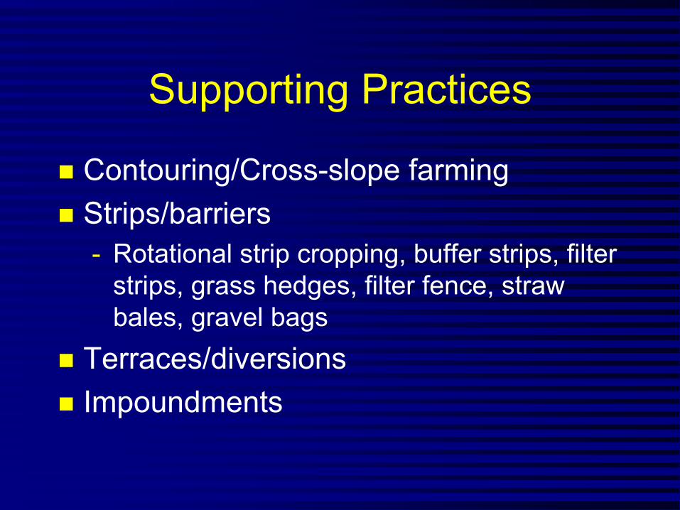
Supporting Practices
� Contouring/Cross-slope farming � Strips/barriers
- Rotational strip cropping, buffer strips, filter strips, grass hedges, filter fence, straw bales, gravel bags
� Terraces/diversions � Impoundments

Contouring/Cross Slope Farming
� Redirects runoff � Fail at long slope lengths � Effectiveness depends on ridge height
- (no ridge height—no contouring effect)

Contouring/Cross Slope Farming (continued)
� Function of: - Ridge height - Row grade - Cover-management - Hydrologic soil group - Storm severity (10 yr EI)
� Varies with time - Tillage that form ridges - Decay of ridges

Critical Slope Length
� If slope length longer than critical slopelength, contouring fails allowing excessive rillerosion
� Function of: - Storm severity, slope steepness, cover-
management, EI distribution � Critical slope length extensions below strips
depend on degree that strip spreads runoff � Terraces are used if changing cover-
management or strips are not sufficient � Soil disturbance required to restore failed
contouring

Buffer/Filter Strips
� Narrow strips of dense vegetation (usuallypermanent grass) on contour - Effective by inducing deposition (partial credit) and
spreading runoff - Most of deposition is in backwater above strip
� Buffer strips - Multiple strips - Either at bottom or not a strip at bottom - Water quality-must have strip at bottom and this
strip twice as wide as others
� Filter strip-single strip at bottom

Rotational Strip Cropping
� Equal width strips on contour � Strips are rotated through a crop rotation
cycle � Offset starting dates among strips so that
strips of close growing vegetation separateerodible strips
� Benefit: - Deposition (full credit) - Spreading runoff - Reduced ephemeral gully erosion not credited in
RUSLE2

Terraces
� Ridges and channels periodically placedalong hillslope that divides hillslope intoshorter slope lengths except for widelyspaced parallel terraces that may have noteffect on slope length
� Benefit: - Shorten slope length and trap sediment - Runoff management system
� Evenly spaced - May or may have a terrace at bottom
� Maintenance required to deal with deposition

Types of TerracesContour line
Gradient terrace
Parallel terrace
Sediment basin into underground tile line
Grassed waterway

Deposition in Terraces
� Deposition occurs when sediment load isgreater than transport capacity
� Sediment load from sediment entering fromoverland area
� Transport capacity function of grade andstorm erosivity
� Deposition depends on sedimentcharacteristics
� Deposition enriches sediment in fines

Diversions
� Ridges and channels placed at strategic locations on hillslope to shorten slope length - Reduce runoff rate and rill erosion
� Generally designed with a steepness sufficiently steep that no deposition occurs but not so steep that erosion occurs

Impoundments (Small sediment control basins)
� Deposition by settling process � Function of:
- Sediment characteristic of sediment load reaching impoundment

Sequencing of Hydraulic Elements
� Hydraulic elements-channels andimpoundments
� Can create a system � Can put channels-impoundments in
sequence � Examples:
- Tile outlet terrace—channel:impoundment - Impoundments in series—
impoundment:impoundment

Benefit of Deposition
� Depends on type of deposition - Local deposition gets full credit - Remote deposition gets partial credit
� Credit for remote deposition - Depends on location on hillslope - Deposition at end gets almost no credit

Subsurface Drainage Systems
� Reflects effects of deep drainage systems- Tile drainage systems- Lateral, deep drainage ditches
� Describe by: - Assigning hydrologic soil group for
undrained and drained soil - Fraction of area drained

Unit 5Databases
Worksheets ContouringProfiles StripsClimate EI distribution Diversion/terrace, Soil sediment basin Management systems Operations Sequence of Vegetation hydraulic elements Residue

Profiles
� Central part of a RUSLE2 soil loss estimate - Profile is reference to a hillslope profile
� Six things describe a profile - Location, soil, topography, management,
supporting practice, hydraulic element system � Topography described with profile
- Can specify segments by length and steepness fortopography, segments by length for soil, segmentsby length for management
� Name and save with a name

Worksheets
� Three parts: Alternative managements,practices; Alternative profiles; Profiles for afield or watershed
� Alternative management, practices - Compare alternatives for a single hillslope profile
� Alternative profiles - Compare specific hillslope profiles
� Field/Watershed - Compute average soil loss/sediment yield for a
field or watershed � Name and save worksheets

Concept of Core Database� RUSLE2 has been calibrated to experimental
erosion data using assumed data values forsuch things as cover-mass, residue atharvest, decomposition coefficient, rootbiomass, burial ratios, etc.
� The data used in this calibration are core calibration values - Data used in RUSLE2 applications must be
consistent with these values � Core databases were set up for vegetation,
residue, and operations - NRCS data manager maintains these databases
� Working databases developed from the coredatabases

Critical RUSLE2 Rules� RUSLE2 DEFINITIONS, RULES,
PROCEDURES, and CORE DATA MUST BE FOLLOWED FOR GOOD RESULTS.
� Can’t independently change one set ofdata without recalibrating.
� Must let RUSLE2 factors and subfactors represent what they were intended to represent. - For example, the K factor values are not to be
modified to represent the effect of organicfarming. The cover-management subfactors represent the effects of organic farming.
� Don’t like these rules—then don’t use RUSLE2 because results won’t be good.

Climate
� Input values for values used to describedweather at a location, county, management zone
� Principal values - Erosivity value, 10 yr EI value, EI distribution,
monthly rainfall, monthly temperature � Designate as Req zone and corresponding
values � Data available from NRCS National Weather
and Climate Center � Name and save by location

EI Distribution
� 24 values that describe distribution of erosivity R throughout year
� For a location, county, management zone, EI distribution zone
� Data available from NRCS Weather and Climate Center
� Name and save

Soil
� Data describes base soil conditions for unit plot conditions
� Data include erodibility value, soil texture,hydrologic soil group of undrained soil, efficient subsurface drainage, time to full soilconsolidation, rock cover
� Erodibility nomograph available to estimatesoil erodibility factor K
� Data available from NRCS soil surveydatabase
� Name and same

Management� Array of dates, operations, vegetations � Specify if list of operations is a rotation
- Rotation is a cycle when operations begin to repeat
- Rotations used in cropping - Rotations often not used immediately after land
disturbances like construction and logging duringrecovery period
- Length of rotation � Yield, depth, speeds of operations � Added materials and amounts � NRCS databases, Extension Service � Name and save
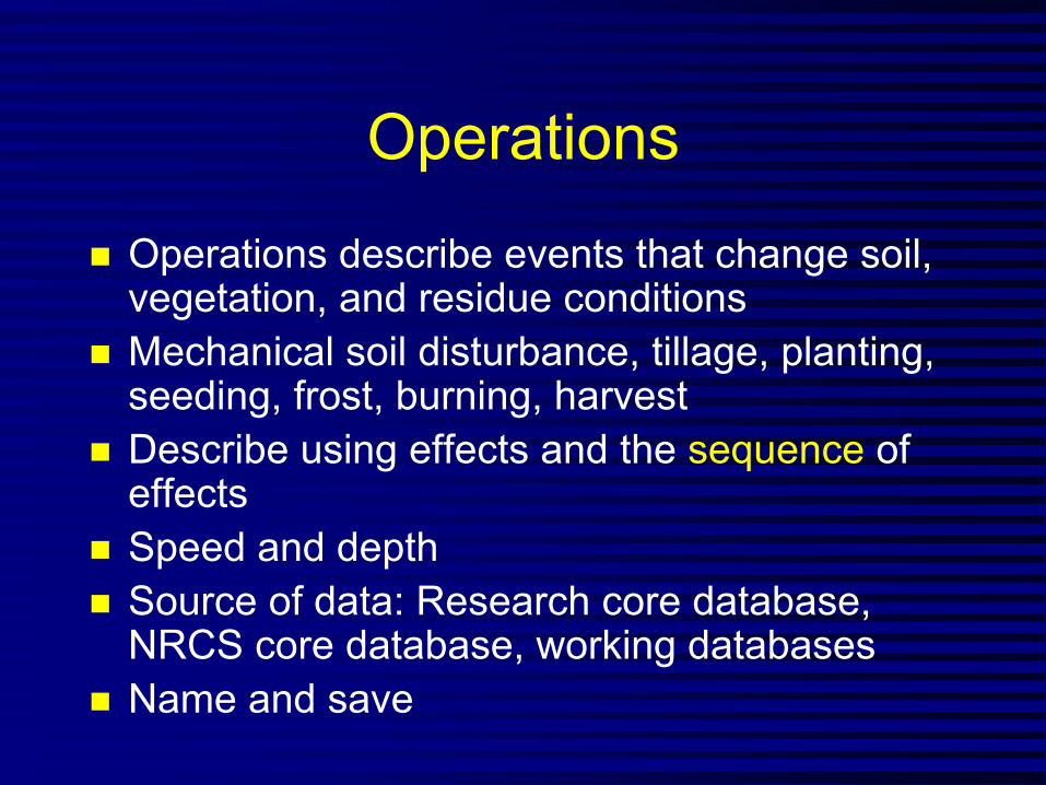
Operations
� Operations describe events that change soil,vegetation, and residue conditions
� Mechanical soil disturbance, tillage, planting,seeding, frost, burning, harvest
� Describe using effects and the sequence of effects
� Speed and depth � Source of data: Research core database,
NRCS core database, working databases � Name and save

Operation Effects
� No effect � Begin growth � Kill vegetation � Flatten standing residue � Disturb surface � Live biomass removed � Remove residue/other cover � Add other cover

Operation Effects (cont)� No effect
- Primarily used to obtain output at particular timesor to add fallow years when not operation occursin that year
� Begin growth - Tells RUSLE2 to begin using data for particular
vegetation starting at day zero - Typically associated with planting and seeding
operations � Kill vegetation
- Transfers mass of above ground live vegetationinto standing residue pool
- Transfers mass live roots into dead root pool - Typically used in harvest and plant killing
operations

Operation Effects (cont)
� Flatten standing residue - Transfer residue mass from standing pool to flat,
ground surface pool - Based on a flattening ratio that is a function of
residue type - Used in harvest operations to determine fraction of
residue left standing after harvest - Used in tillage and other operations involving
traffic to determine fraction of residue left standing after operation

Operation Effects (cont)� Disturb surface
- For mechanical soil disturbance that loosens soil - Tillage type (inversion, mixing+some inversion,
mixing only, lifting fracturing, compression)determines where residue is placed in soil andhow residue and roots are redistributed within soil
- Buries and resurfaces residue based on ratios that depend on residue type
- Tillage intensity (degree that existing roughness isobliterated)
- Recommended, minimum, maximum depths - Initial ridge height - Initial, final roughness (for the base condition) - Fraction surface area disturbed (tilled strips)

Operation Effects (cont)
� Live biomass removed - Fraction removed - Fraction of that removed that is “lost” and left as
ground cover (flat residue) - Used with hay and silage harvest operations
� Remove residue/other cover - All surface residues affected or only most recent
one?- Fraction of standing cover removed- Fraction of flat cover removed- Used in baling straw, burning operations

Operation Effects (cont)
� Add other cover - Fraction added to surface versus fraction placed in
soil - Unless all mass added to surface, must be
accompanied by disturbed soil effect (that is, mass can not be placed in soil without disturbance)
- Mass placed in soil is placed between ½ and maximum depth
- Used to add mulch and manure to surface, inject manure into soil

Vegetation� Live plant material � Static variables include:
- Residue name, yield, retardance, senescence,moisture depletion for NWRR
� Time varying variables - Root biomass in upper 4 inches - Canopy cover percent - Fall height - Live ground (surface) cover cover percent
� Source of data: Research core database, NRCS core database, working databases
� Name and save

Yield-Residue Relationship
� Residue at max canopy function of yield
Yield 1
Yield
Resi
Residue 1
Residue 2
Yield 2
due at Max Canopy

Yield-Retardance Relationship
� Retardance function of yield, on contour, and up and down hill
Retardance Retardance at a high yield
Significant retardance at no yield (wheat)
No retardance at no yield No retardance at a significant yield (corn) (grass) Yield

Retardance for Up and Downhill
� RUSLE2 chooses retardance based on row spacing and the retardance selected for astrip of the vegetation on the contour - How does vegetation slow the runoff?
� Row spacing - Vegetation on ridge-no retardance effect - Wide row-no retardance effect (> 30 inches
spacing) - No rows, broadcast-same as strip on contour - Narrow row-small grain in about 7 inch spacing - Very narrow-same as narrow row except leaves
lay in row middle to slow runoff - Moderate-about 15 to 20 inches spacing

Residue� Size, toughness
- 5 types: small, fragile (soybeans); moderate size, moderately fragile (wheat); large size, nonfragile (corn); large size, tough (woody debris); gravel, small stones
� Decomposition (coefficient, halflife) � Mass-cover values � Source: NRCS databases � Name and save
90%
Enter 1 of 3 pts. % Cover 60% Mass @ 30, 60, or 90%
cover 30%
0 0
Mass per unit area

Senescence
� Input the fraction of the biomass at maxcanopy that falls to soil surface when canopydecreases from its max value to its min value.
� Input the minimum canopy value thatcorresponds to fraction that experiences senescence
� Mass that falls is computed from difference incanopy percentages and nonlinearrelationship between canopy percent and canopy mass

Contouring/Cross Slope Farming
� To have contouring, must have ridge heights - To have ridge height, must have operation - Ridge height assigned in operation
� Row grade - Relative row grade (preferred) or absolute
� Create contouring practices based on relativerow grade (row grade/land slope) - Perfect (0%), exceeds NRCS specs (5%), meets
specs (10%), Cross slope (25%), Cross slope(50%)
� Name and save contouring practice

Strips/Barriers
� Types - Filter, buffer, rotational strip cropping
� Filter - Specify width and management on strip
� Buffer - Specify number, whether strip at bottom, for
erosion or water quality control, width, strip management
� Rotational strip cropping - Specify number, timing of rotation on each strip
� Name and save

Hydraulic Elements and Their Sequence
� Channels - Specify grade
� Impoundments - Nothing to specify
� Specific order of elements � Name and save sequence

System of Hydraulic Elements
� System composed of named sequence of hydraulic elements
� Number of systems on hillslope � Is the last one at the bottom of the
slope? � Name and save systems

Subsurface Drainage Systems
� Represented by: - Hydrologic soil group for soil when it is well
drained • Entered in soil input
- Fraction of area that is drained � Name and save

UNIT 6
Applicability

LIMITS OF APPLICABILITY
� How well does RUSLE apply to this situation?- Erosion Processes
- Land Uses
- Geographic Regions
- Temporal Scale
- Uncertainty in computed values

APPLICABLE PROCESSES
� Yes: Interrill and rill erosion� Yes: Sediment yield from overland flow slope
length � Yes: Sediment yield from terrace channels
and simple sediment control basins � No: Ephemeral or permanent incised gully
erosion � No: Stream channel erosion � No: Mass wasting

Applicable Land Uses
� All land uses where overland flow and interrill-rill erosion occurs
� Land use independent � Best: Cropland � Moderate: Disturbed lands like military lands,
construction sites, landfills, reclaimed lands
� Acceptable: Rangelands, disturbed forestlands, parks and recreational areas

Cropland Applications
� Best: Clean tilled corn, soybean, wheat crops
� Moderate: Conservation tillage, rotations involving hay
� Acceptable: Hay, pasture � Most variable: Support practices,
especially contouring
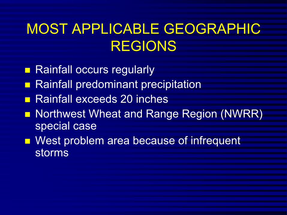
MOST APPLICABLE GEOGRAPHIC REGIONS
� Rainfall occurs regularly � Rainfall predominant precipitation � Rainfall exceeds 20 inches � Northwest Wheat and Range Region (NWRR)
special case� West problem area because of infrequent
storms

APPLICABLE SOILS
� Best: Medium Texture � Moderate: Fine Texture � Acceptable: Coarse Texture � NO: Organic

APPLICABLE TOPOGRAPHY
� Slope Length - Best: 50 - 300 feet - Moderate: 0 - 50 ft , 300 - 600 ft. - Acceptable: 600 - 1000 feet - NO: >1000 feet

APPLICABLE TOPOGRAPHY
� Slope Steepness - Best: 3 - 20% - Moderate: 0 - 3%, 20 - 35% - Acceptable: 35 - 100% - NO: >100%

UNCERTAINTY
� Best (±25%): 4 < A < 30 t/ac/yr � Moderate (±50%): 1 < A < 4
30 < A < 50 � Least (>±100%): A < 1
(>±50%): A > 50
Confidence in Result

Significant Change
� Rule of thumb: - A change in a RUSLE2 soil loss estimate by more
than 10% is considered significant and meaningful in terms of representing main effect.
- An change less than 10% is not consideredsignificant in general
� The accuracy for RUSLE2 representing howmain effects affect soil loss is much better than the absolute accuracy for RUSLE2estimating soil loss at any particular locationand landscape condition.

TEMPORAL APPLICABILITY
� Best: Average annual, average annual
season, average annual single day
� Least: Single storm provided great care
used, generally not recommended

Sensitivity
� Change in soil loss per unit change in aparticular variable
� Select a base condition � Vary input values for a variables about
base condition � Sensitivity varies according to condition� Variables with greatest sensitivity
require greatest attention

Examples of Sensitivity
� Some variables have a linear effect - Erosivity factor R - Slope steepness
� Effect of most variables is nonlinear - Ground cover - Below ground biomass - Roughness

Examples of Sensitivity (cont)
� Low sensitivity - Slope length at flat slopes (0.5%) A= 4.6
t/a at κ = 150 ft, 5.2 t/a at κ = 500 ft, 5.5 t/a at κ = 1000 ft
� Moderate sensitivity - Slope length at steep slopes (20%) A =
129 t/a at κ = 50 ft, A = 202 t/a at κ = 100 ft, A = 317 t/a at κ = 200 ft.

Examples of Sensitivity (cont)
� High sensitivity-Ground cover single most important - Adding mulch
� Most variables interrelated - Ground cover at planting not as much as expected
� Sequence of operations - Effect of depth for a tandem disk - Depends on whether proceeded by moldboard
plow

SUMMARY
� RUSLE varies in its applicability
� Results from RUSLE must be judged
� Degree of confidence in results varies