Revised Point of Departure Design Options for Nuclear ... · Revised Point of Departure Design...
14
American Institute of Aeronautics and Astronautics 1 Revised Point of Departure Design Options for Nuclear Thermal Propulsion James E. Fittje 1 and Stanley K. Borowski 2 NASA Glenn Research Center, Cleveland, OH and Bruce Schnitzler 3 Oak Ridge National Laboratory, Oak Ridge, TN In an effort to further refine potential point of departure nuclear thermal rocket engine designs, four proposed engine designs representing two thrust classes and utilizing two different fuel matrix types are designed and analyzed from both a neutronics and thermodynamic cycle perspective. Two of these nuclear rocket engine designs employ a tungsten and uranium dioxide cermet (ceramic-metal) fuel with a prismatic geometry based on the ANL-200 and the GE-710, while the other two designs utilize uranium-zirconium- carbide in a graphite composite fuel and a prismatic fuel element geometry developed during the Rover/NERVA Programs. Two engines are analyzed for each fuel type, a small criticality limited design and a 111 kN (25 klbf) thrust class engine design, which has been the focus of numerous manned mission studies, including NASA’s Design Reference Architecture 5.0. Nomenclature ANL = Argonne National Lab cermet = ceramic-metallic fuel containing ceramic particles in a metal matrix GE = General Electric HTGR = High Temperature Gas Reactor Isp = specific impulse K = temperature in Kelvin kg = mass in kilograms klbf = kilopounds of force kN = kilonewtons of force lbm = pounds mass MCNP = Monte Carlo N-Particle transport code MPa = pressure in megapascals MWth = megawatts thermal power NERVA = Nuclear Engine for Rocket Vehicle Applications NESS = Nuclear Engine System Simulation code NTR = Nuclear Thermal Rocket Psia = absolute pressure in pounds per square inch R = temperature in Rankine SNRE = Small Nuclear Rocket Engine TPA = Turbo-Pump Assembly 1 Vantage Partners, LLC at GRC, 3000 Aerospace Parkway, Brook Park, OH, AIAA Senior Member. 2 Lead Engineer, NTP Systems, 21000 Brook Park Road, MS:86-4, AIAA Associate Fellow. 3 Senior R&D Staff, Advanced Reactor Concepts, MS-6165, Oak Ridge National Laboratory, Oak Ridge, TN, AIAA Senior Member. https://ntrs.nasa.gov/search.jsp?R=20150021278 2018-09-06T15:30:37+00:00Z
-
Upload
vuongduong -
Category
Documents
-
view
218 -
download
0
Transcript of Revised Point of Departure Design Options for Nuclear ... · Revised Point of Departure Design...
American Institute of Aeronautics and Astronautics
1
Revised Point of Departure Design Options for Nuclear
Thermal Propulsion
James E. Fittje1 and Stanley K. Borowski2
NASA Glenn Research Center, Cleveland, OH
and
Bruce Schnitzler3
Oak Ridge National Laboratory, Oak Ridge, TN
In an effort to further refine potential point of departure nuclear thermal rocket engine
designs, four proposed engine designs representing two thrust classes and utilizing two
different fuel matrix types are designed and analyzed from both a neutronics and
thermodynamic cycle perspective. Two of these nuclear rocket engine designs employ a
tungsten and uranium dioxide cermet (ceramic-metal) fuel with a prismatic geometry based
on the ANL-200 and the GE-710, while the other two designs utilize uranium-zirconium-
carbide in a graphite composite fuel and a prismatic fuel element geometry developed during
the Rover/NERVA Programs. Two engines are analyzed for each fuel type, a small criticality
limited design and a 111 kN (25 klbf) thrust class engine design, which has been the focus of
numerous manned mission studies, including NASA’s Design Reference Architecture 5.0.
Nomenclature
ANL = Argonne National Lab
cermet = ceramic-metallic fuel containing ceramic particles in a metal matrix
GE = General Electric
HTGR = High Temperature Gas Reactor
Isp = specific impulse
K = temperature in Kelvin
kg = mass in kilograms
klbf = kilopounds of force
kN = kilonewtons of force
lbm = pounds mass
MCNP = Monte Carlo N-Particle transport code
MPa = pressure in megapascals
MWth = megawatts thermal power
NERVA = Nuclear Engine for Rocket Vehicle Applications
NESS = Nuclear Engine System Simulation code
NTR = Nuclear Thermal Rocket
Psia = absolute pressure in pounds per square inch
R = temperature in Rankine
SNRE = Small Nuclear Rocket Engine
TPA = Turbo-Pump Assembly
1 Vantage Partners, LLC at GRC, 3000 Aerospace Parkway, Brook Park, OH, AIAA Senior Member. 2 Lead Engineer, NTP Systems, 21000 Brook Park Road, MS:86-4, AIAA Associate Fellow. 3 Senior R&D Staff, Advanced Reactor Concepts, MS-6165, Oak Ridge National Laboratory, Oak Ridge, TN, AIAA
Senior Member.
https://ntrs.nasa.gov/search.jsp?R=20150021278 2018-09-06T15:30:37+00:00Z

American Institute of Aeronautics and Astronautics
2
I. Introduction
he Nuclear Thermal Rocket (NTR) engine concept is being evaluated as a potential propulsion technology for
numerous human exploration, cargo deployment, and robotic probe missions1-4. The need for high performance
propulsion systems in these missions has been documented in numerous studies, including NASA’s Design Reference
Architecture 5.0. These studies have shown NTR based systems to provide superior performance for these high delta-
V missions, compared to various electric and chemical propulsion concepts. Nuclear thermal propulsion system
development was the primary focus of a considerable effort undertaken during the Rover/NERVA, GE-710, and
Argonne National Lab (ANL) nuclear rocket programs from 1955 to 19735-7, which preformed both extensive engine
component and fuels development, and resulted in multiple full scale engine tests using graphite matrix fuel.
In an effort to further refine potential point of departure NTR engine designs, four proposed engine designs
representing two thrust classes and utilizing two different fuel types are analyzed from both a neutronics and
thermodynamic cycle perspective. Two of these nuclear rocket engine designs employ a tungsten and uranium
dioxide cermet fuel with a prismatic geometry based on the ANL-200 and GE-710, while the other two designs utilize
the uranium carbide based composite fuel matrix and a prismatic fuel element geometry developed during the
Rover/NERVA program. Two engines are analyzed for each fuel type, a small criticality limited design and a 111 kN
(25 klbf) thrust class engine design. The 111 kN (25 klbf) thrust class has been the focus of numerous manned mission
studies, including NASA’s Design Reference Architecture 5.08 .
In order to evaluate these engine designs, a highly detailed Monte Carlo N-Particle (MCNP) model of each engine
is first developed and exercised in order to determine the thermal energy deposition rate in the various engine
components via decelerating fission products and scattered neutrons and photons. These results, along with additional
rocket engine design inputs such as the desired chamber pressure, nozzle area ratio, cycle type, and flow circuit
pressure drops are then utilized in NASA’s Nuclear Engine System Simulation (NESS) code to determine engine
cycle state points, overall engine performance, and to estimate both engine mass and dimensions.
II. NTR System Overview
A typical NERVA derived NTR propulsion system is shown in Fig. 1. These systems typically consist of a small
nuclear fission reactor, turbo pump assembly (TPA), nozzle, radiation shields, neutron reflector, pressure vessel,
control drums, and various propellant lines and support hardware. They are typically expander cycle based, and thus
utilize thermal energy gained by the hydrogen propellant from actively cooling various engine subcomponents
(nozzle, control drums, etc.) to drive the turbine, and thus power the cycle. As NTR engine designs evolved during
the NERVA program, chamber pressure and engine size increased, thus additional thermal energy was required to
meet the increasing turbine drive power requirements. To satisfy this requirement, designs began to extract additional
thermal energy directly from the reactor core by actively cooling the tie-tube structural support elements5-7. Although
this arrangement is integral to the NERVA derived designs, the cermet based designs don’t utilize tie-tubes, thus their
chamber pressure and thrust level are limited by the amount of thermal energy available to the turbine drive flow via
active cooling of various engine components. Once above this operational limit, additional thermal energy is required
to close the thermodynamic cycle. Previous studies have explored using opposing pairs of low power fuel elements at
the periphery of the reactor to supply the additional thermal energy by placing them in a parallel cooling flow path to
the radial reflector and control drums9. The work presented here follows this design philosophy for the cermet based
designs, but only if required by the engine cycle. Simplified flow diagrams of both the NERVA derived and cermet
based engine cycles are shown in Fig. 2.
T

American Institute of Aeronautics and Astronautics
3
A. Engine Cycle
Several thermodynamic cycles were explored for use in NTR engine design during the Rover/NERVA program,
with the closed expander cycle being studied extensively and ultimately chosen for the SNRE. This particular cycle
has also been used extensively in upper stage cryogenic engines such as the RL10. In a closed expander cycle, the
energy to drive the TPA is obtained by regeneratively cooling various engine components during its operation,
epically the nozzle and thrust chamber. In a NERVA derived NTR system, heat is also obtained from multiple other
components, including the radial reflector, control drums, and filler elements. In order to provide structural support to
the reactor core, neutron moderation, and additional heat for the turbine drive flow, tie-tubes are utilized which are
capable of providing adequate thermal energy to the TPA drive flow to sustain adequate chamber pressures and
propellant mass flow rates. The NERVA derived closed expander cycle is shown on the left in Fig.2, and is used in
both the criticality limited and the larger 111 kN (25 klbf) class NERVA derived engines presented here.
Unlike the NERVA derived NTR engine designs that utilized tie-tubes to obtain thermal energy from the reactor
core to drive the TPA, the cermet designs use heat obtained solely from actively cooling various engine
subcomponents such as the regeneratively cooled nozzle and thrust chamber, control drums, radial reflector, and the
reactor core filler elements. Although these components can supply several megawatts of thermal energy to the TPA
drive flow, previous studies have shown that this class of engine design is turbine drive power limited, and simply
can not provide sufficient propellant mass flow to both adequately cool the reactor and maintain a nominal pressure
in the thrust chamber9. In order to avoid this limitation, the designs presented here utilize two different approaches.
The criticality limited engine uses the ANL-200 fuel element geometry and only utilizes active cooling of engine
components to obtain turbine drive power. The larger engine, however, is based on a modified GE-710 design and
utilizes fuel elements located at the core periphery to obtain additional turbine drive power, and thus a higher
chamber pressure. This is accomplished by splitting the regeneratively cooled nozzle exit flow (state point 5 in Fig. 2)
into to two parallel cooling paths with one cooling the radial reflector and control drum assemblies, and the other
flowing hydrogen through these heater elements. These two flows are then recombined at their respective exits and
sent to the turbine. This flow path is shown on the right in Fig. 2.
Figure 1. Typical NERVA Derived NTR Engine System.

American Institute of Aeronautics and Astronautics
4
B. Reactor Assembly
In a SNRE derived NTR system, a large number of tie-tubes and fuel elements are assembled together to create
the reactor core. In this assembly, the ratio of fuel elements to tie-tubes is adjustable, but a typical arrangement is one
in which each tie-tube is surrounded by six fuel elements, and each fuel element is in contact with three tie-tubes6,10.
The fuel elements around the perimeter of the core, however, may contact fewer tie-tubes. This reactor core assembly
is surrounded by partial hexagonal filler elements, which then form a cylindrical reactor core. The cylindrical core
assembly is then placed inside a beryllium radial reflector assembly which also houses the control drums. The control
drums consist of a neutron moderator-reflector on one side and a neutron absorber on the other, and are the same
length as the tie-tubes and the fuel elements. Reactor reactivity is controlled via rotation of these control drums, and
thus the reactor power level can be adjusted. This entire assembly is then placed inside an aluminum alloy pressure
vessel to which the nozzle is attached6,7. A cross section view of a typical SNRE derived reactor assembly is shown in
Fig. 3.
NERVA Derived Flow Path Cermet Based Flow Path
Figure 2. NTR Cycle Flow Diagrams.

American Institute of Aeronautics and Astronautics
5
For a cermet based NTR design, the overall reactor assembly follows the same basic design as the NERVA
derived systems. The major difference between the two is the lack of tie-tubes in the cermet based designs. Due to
differences in their neutron spectrums, the cermet designs do not require tie-tubes for neutron moderation, thus
resulting in a smaller diameter reactor. This smaller core is also encircled by partial filler elements and the entire core
assembly is placed within a beryllium radial reflector that houses the control drums. Other differences in the reactor
assembly include the substitution of certain materials for those that are better suited to the neutron spectrum of the
specific design, and the inclusion of an axial beryllium oxide reflector at the cold end of the reactor which is unique
to the cermet based systems.
C. Fuel Elements and Tie-Tubes
A tie-tube is a hexagonal shaped axial support element which also serves as a dual pass heat exchanger through
the length of the reactor core. Cold hydrogen propellant is first sent down the center of the tie-tube and then returns
via an outer coaxial annular flow path. During this process, it extracts thermal energy from the reactor core, which is
later used to drive the turbine. Tie-tubes have identical cross-sectional dimensions as the fuel elements, but are
slightly longer in order to accommodate feed system plumbing on the cold inlet end and fuel element support
hardware on the hot end6,7. They not only give axial support to the fuel elements, but also provide neutron moderation
and the thermal energy required thermodynamically close the engine’s cycle. These elements are unique to the
NERVA derived NTR systems, and are not present in the cermet based designs.
The NERVA derived fuel elements are hexagonal in cross-section, have 19 equally spaced hydrogen flow
channels that run the entire length of the fuel element, and a 50 micrometer thick ZrC surface coating 6,7. The fuel
matrix selected for use in both the NERVA derived engine designs presented here is the (U,Zr)C-graphite composite
fuel. This particular fuel was tested during the NERVA program in the Nuclear Furnace 1 test reactor11,12, has a
higher operational temperature relative to pyrocarbon coated UC2 particles in graphite, and is well characterized.
Because it has design heritage with numerous NTR engines, and was the baseline fuel in the SNRE design, it is
Fuel Element
Tie-Tube
Pressure Vessel
Tie-Tubes
Fuel Elements
Control Drums
Beryllium Reflector
Neutron Absorber
Fuel Element
Tie-Tube
Pressure Vessel
Tie-Tubes
Fuel Elements
Control Drums
Beryllium Reflector
Neutron Absorber
Figure 3. Typical NERVA Derived Reactor Cross Section.

American Institute of Aeronautics and Astronautics
6
selected for the analysis presented here. A typical NERVA derived fuel element and tie-tube integration arrangement
is shown in Fig. 4, and fuel element and tie-tube cross section details are shown in Fig. 5.
1.913 cm
0.13 mm Gap
Inner Tie Tube
(5.21 mm OD x
0.51 mm wall)
Hydrogen
Supply
Passage
Hydrogen
Return Passage
ZrH Moderator (5.33 mm ID
x 11.68 mm OD)
Outer Tie Tube
(13.97 mm OD x
0. 205 mm wall)
Graphite Filler Structure
(16.26 mm ID)
0.13 mm Gap
ZrC, (16.13 mm OD
x 14.10 mm ID)
Hydrogen Cooling Passage
(19 per Element, ~2.54 mm Dia)
(UC-ZrC)C Composite
Fuel MatrixZrC Coating
ZrC Coating
0.13 mm Gap1.913 cm
0.13 mm Gap
Inner Tie Tube
(5.21 mm OD x
0.51 mm wall)
Hydrogen
Supply
Passage
Hydrogen
Return Passage
ZrH Moderator (5.33 mm ID
x 11.68 mm OD)
Outer Tie Tube
(13.97 mm OD x
0. 205 mm wall)
Graphite Filler Structure
(16.26 mm ID)
0.13 mm Gap
ZrC, (16.13 mm OD
x 14.10 mm ID)
Hydrogen Cooling Passage
(19 per Element, ~2.54 mm Dia)
(UC-ZrC)C Composite
Fuel MatrixZrC Coating
ZrC Coating
0.13 mm Gap
a) Typical NERVA Derived Fuel Element b) Typical NERVA Derived Tie Tube
Figure 5. Tie-Tube and Fuel Element Cross Sections. Tie-Tube gaps represent cold (not operating) conditions.
Figure 4. Typical NERVA Derived Fuel Element and Tie-Tube Arrangement.

American Institute of Aeronautics and Astronautics
7
The prismatic fuel elements used in the cermet based engine designs are based on the ANL-20013 and those
developed under the GE-710 HTGR programs. Both fuel elements utilize a cladding comprised of W /25% Re by
volume and have a fuel matrix composition of W -60% UO2 -6% Gd2O3 with a constant enrichment of 235U of 93%
by weight, which is assumed to be at 100% theoretical density. The criticality limited engine uses the ANL-200 fuel
element geometry, while the larger 111 kN (25 klbf) class engine uses the theoretical GE-711 fuel element geometry.
In the GE-711 design, the propellant channel diameter is increased to 1.118 mm (0.044 in) from the 0.914 mm
(0.036in) used in the GE-710 design14, thus resulting in flow passages that are 50% larger in cross sectional area. The
fuel elements used in the larger cermet engine are also shorter, having a 60.96 cm (24 in) active fuel length. A
comparison of the ANL-200, GE-710, and GE-711 cermet fuel element geometries is shown in Table 1, and a
comparison of the ANL-200, GE-711, and NERVA derived fuel element cross sections is shown in Fig. 6.
Table 1. Cermet Fuel Element Geometry Summary.
Fuel Element Geometry ANL-200 GE-710 GE-711
Fuel Element Width w/o Clad 7.838 cm 1.078 in 2.278 cm 0.8976 in 2.278 cm 0.8976 in
Fuel Element Width with Clad 2.774 cm 1.092 in 2.361 cm 0.9296 in 2.361 cm 0.9296 in
Outer Cladding Thickness 0.178 mm 0.007 in 0.381 mm 0.015 in 0.381 mm 0.015 in
Fuel Element Length 71.12 cm 28.00 in 60.96 cm 24.00 in 60.96 cm 24.00 in
Fuel Composition W -60% UO2 -6% Gd2O3
Cladding Composition W / 25% Re
Coolant Channels per Element 61 91
Coolant Channel Diameter w/o Clad 2.057 mm 0.081 in 1.321 mm 0.052 in 1.524 mm 0.060 in
Coolant Channel Diameter with Clad 1.702 mm 0.067 in 0.914 mm 0.036 in 1.118 mm 0.044 in
Coolant Channel Pitch 3.454 mm 0.136 in 2.353 mm 0.0938 in 2.353 mm 0.0938 in
III. NTR Engine Model
NTR engine design and evaluation is an iterative process involving neutronic, thermodynamic engine cycle, and
engine system analysis. An effective design and analysis sequence is to first determine a reactor core configuration
that meets criticality requirements. The results from this neutronic analysis are used to provide the thermal energy
deposition rates of the various reactor components to an integrated thermal-fluid-structural analysis of the engine
system. Once acceptable neutronic and engine cycle performance is achieved, the overall engine system performance
can be evaluated.
A. MCNP Model
The MCNP model of the NERVA derived NTR engine designs begins by explicitly modeling the composite fuel
elements and tie tubes, shown in Fig. 5. These fuel elements have an active fuel length of 89 cm (35 in) for the
criticality limited engine and 132 cm (52 in) for the 111 kN (25 klbf) class engine. The two fuel element models
explicitly incorporate the 19 propellant coolant channels that have a 0.2565 cm (0.101 in) borehole diameter, a
Figure 6. Fuel Element Cross Section Compairson. Elements are shown to relative scale.

American Institute of Aeronautics and Astronautics
8
borehole pitch of 0.40894 cm (0.161 in), and the 50 micrometer thick ZrC outer surface coating. The support arches
below each fuel element and most of the hot end support assembly are incorporated into a lower extension of the fuel
element model. Once the reactor core assembly of fuel elements and tie-tubes is complete, the filler elements are
added along with the surrounding structure, beryllium reflector, control drums, and other engine system components.
The cermet based engines are modeled in a similar fashion, with all of the propellant channels, fuel matrix, and
surfaces coatings for both the ANL-200 and GE-711 fuel elements being explicitly modeled. The active fuel lengths
modeled in the criticality limited and 111 kN (25 klbf) class cermet based engines are 71 cm (28 in) 61 cm (24 in)
respectively.
Once the MCNP models have reached convergence15,16, the total energy deposition rate (sum of neutron and
gamma deposition) into the various engine components, as well as the associated spatial distributions for the fuel
elements and tie-tubes, are exported to NESS. For the four models used in this analysis, the energy deposition rate
data are summed over the length of each fuel element and tie-tube, and a normalized axial distribution profile is
provided to NESS from MCNP, which is discretized in 1.0 cm (0.39 in) increments. Both the individual thermal
energy deposition rate data and the axial profile data are then used to construct a unique discretized thermal energy
deposition rate profile for each individual fuel element. Previous work has shown that there are no appreciable
differences in the normalized axial thermal power profile of either the tie-tubes or fuel elements based on their radial
or circumferential locations in the reactor core for a 90-degree control drum setting. This allows for a single
normalized axial profile to be applied across all the fuel elements and tie-tubes in a given composite or cermet based
engine design14,17.
B. NESS Model
The NESS models begin by utilizing the mass and
thermal energy deposition data from the above
mentioned MCNP analysis for all the fuel elements, tie-
tubes, filler elements, control drums, beryllium barrel,
stainless steel wrapper, pressure vessel, upper and lower
tie-tube plenums (NERVA based designs only), brim
shield, internal shields, axial reflector (cermet designs
only), and numerous hydrogen gaps. NESS uses this
information in mass summations and as thermal energy
sources for the thermodynamic cycle calculations. The
flow splits in the engine cycle are also modeled,
corresponding to those shown in Fig. 2. Additional inputs
into the NESS models include adiabatic pump and
turbine efficiencies, appropriate fuel thermal
conductivity data, various component pressure drops,
fuel element geometry and coating thicknesses, chamber
pressure, and nozzle area ratio. The 15.24 cm (6.00 in)
thick axial BeO reflector is present only in the cermet
designs, and is treated computationally as a fuel element
extension. Once the reactor inlet pressure and mass flow
rate are obtained, the engine flow circuit is solved via
iteration until a TPA power balance is achieved17-19.
Both the thrust chamber and nozzle on all four
designs are regeneratively cooled to an area ratio of 25:1. The nozzle is then continued to an area ratio of 300:1 by a
radiatively cooled and retractable carbon composite nozzle. The SNRE used an uncooled nozzle extension which
folded about a hinge located at the edge of the nozzle circumference2,3. The designs presented here utilize an RL10B-
2 style nozzle deployment mechanism, which allows a portion of the uncooled nozzle extension to be retracted
around the engines thrust chamber and power head assembly. This design can effectively reduce the stowed length of
an NTR engine by approximately 30%20. The deployment mechanism consists of a support structure, control
electronics, a drive motor, and a set of belt driven ball screw actuators that axially translate the nozzle skirt from its
stowed position to its deployed position20,21. An RL10B-2 equipped with this system is shown in Fig. 7
All four of the engine designs analyzed use adiabatic pump and turbine efficiency values of 65% and 80%
respectively. These values are lower than what can be expected with current start of the art TPAs22, but for
comparison with previous designs, including the SNRE2,3, the more conservative values are used. A peak fuel
temperature of 2860 K (5148 R) is used by NESS for both the composite and cermet fuels, and all the fuel elements
Figure 7. RL10B-2 with Retracted Nozzle Extension.

American Institute of Aeronautics and Astronautics
9
are individually orificed during analysis to reduce the hydrogen mass flow rate in their cooling passages. This results
in every fuel element reaching the peak allowable fuel temperature, thus maximizing the hydrogen outlet temperature
and the resulting Isp.
The 111 kN (25 klbf) thrust class engine designs are both analyzed at a chamber pressure of 6.89 MPa (1,000
psia). Although this chamber pressure is not an issue for the NERVA derived designs, it is found to be an issue for
the cermet based engine. In order to obtain sufficient turbine drive power, fuel elements around the core periphery are
added to the flow circuit in opposing pairs. This flow is modeled by flowing hydrogen through these heater elements
from the hot end to the cold end until the peak allowable fuel temperature is reached at a point along one of heater
elements without any orificing. The flow exiting these elements (state point 7 on Fig.2) is then combined with the
parallel branch that cooled the reflector and control drums, and the resulting flow stream sent to the turbine. The
criticality limited cermet based design is also turbine drive power limited, but due to its small size, it is undesirable to
use dedicated heater elements to close the engine cycle. It was decided to run the criticality limited cermet engine
model to as high a chamber pressure as the cycle would realistically allow without supplementary heater elements,
and then apply the same chamber pressure to the NERVA derived criticality limited design for comparison.
IV. Model Results
The normalized total thermal energy deposition rate profiles for both the criticality limited and 111 kN (25lbf)
thrust class NERVA derived engine core cross-sections are shown in Fig 8. These two cores have a normalized peak-
to-average thermal energy deposition rate ratio of 1.23 and 1.14 respectively. To help achieve criticality in as small
an engine design as possible, the criticality limited design required a modified tie-tube and fuel element pattern that
consists of thirteen rows of tie-tubes which separate adjacent rows of fuel elements. The larger NERVA derived
engine maintained the original SNRE based pattern. The normalized axial thermal energy deposition rate profiles for
both NERVA derived designs is shown in Fig. 9, and they display a high degree of similarity both to each other and
to those of other engine NERVA derived NTR engine designs14,18,20,.
Figure 8. MCNP Determined Thermal Energy Deposition Rates. Profiles represent normalized total element
thermal energy deposition rates for the two NERVA derived engine designs.

American Institute of Aeronautics and Astronautics
10
The thermal energy deposition rate data calculated by MCNP are used by NESS in conjunction with other design
parameters to determine overall engine system performance. A summary of this analysis is shown in Table 2, and
includes various engine component masses, dimensions, and engine performance parameters. Although the criticality
limited design has ample turbine drive power available, for this analysis its chamber pressure was limited to the 3.89
MPa (565 psia) obtained by the criticality limited cermet design for comparison purposes. The 111 kN (25 klbf) thrust
class engine has a higher T/W relative to the criticality limited design, which is partially due to the extra tie-tubes
required by the criticality limited design. These are required to satisfy reactor neutronics requirements and not to
obtain adequate turbine drive power. The larger engine design also had a higher delivered Isp, due primarily to its
longer fuel elements which give the hydrogen propellant additional contact time.
Table 2. System Summaries for the NERVA Derived Engine Designs.
NERVA Derived Designs
Criticality-Limited (7.5 klbf Thrust Class) 111 kN (25 klbf) Thrust Class
Masses (kg) (lbm) (kg) (lbm)
Fuel Elements (FE) 207.7 457.8 612.8 1,350.7
Tie Tubes (TT) 231.0 509.1 313.7 691.4
Heater Elements (HE) - -
Reflector Assembly 717.7 1,581.8 1,141.6 2,516.0
Pressure Vessel 87.9 193.8 284.7 627.5
TPA 9.1 20.0 41.4 91.3
TVC, Lines, and Valves 38.2 84.2 85.8 189.1
Nozzle 81.0 178.6 149.8 330.1
Assorted Hardware 416.4 917.7 708.1 1,560.7
Engine Mass 1,789.0 3,943.0 3,338.0 7,357.0
Dimensions (cm) (in) (cm) (in)
Core / FE Length 89.0 35.0 132.0 52.0
TPA / TVC System Length 178.1 70.1 228.3 89.9
Pressure Vessel Length 207.1 81.5 320.9 126.3
Nozzle Length 233.7 92.0 320.2 126.1
Figure 9. Normalized Axial Thermal Energy Deposition Rate Profile. NERVA derived engine designs.

American Institute of Aeronautics and Astronautics
11
Nozzle Exit Diameter 137.9 54.3 189.0 74.4
Approx. Total Engine Length 618.9 243.7 869.4 342.3
Engine Parameters
No. Elements (FE/TT/HE) 260 / 251 / 0 564 / 241 / 0
Core Power Level 157 MWt 563 MWt
Chamber Pressure 3.89 MPa 565 psia 6.89 MPa 1,000 psia 235U Mass 27.5 kg 12.5 lbm 36.8 kg 16.7 lbm
Thrust 33.4 kN 7.52 klbf 111.2 kN 25.18 klbf
Thrust-to-Weight Ratio 1.91 3.42
Delivered Isp (s) 894 909
Similar to the NERVA derived engine designs, the MCNP results for both the cermet based designs also include
thermal energy deposition rate data for the major reactor core components. The fuel elements are also represented by
both individual thermal energy deposition rate values and an axial distribution profile. The normalized thermal
energy deposition rate profiles for both cermet engine core cross-sections are shown in Fig 10. Figure 10 also shows
the location of the twelve dedicated heater elements that are required to close the thermodynamic cycle of the 111 kN
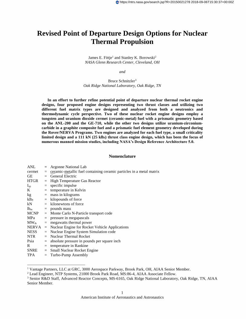
(25 klbf) thrust class engine. Figure 11 shows the normalized axial thermal energy deposition rate profiles for both
cermet based reactor cores. Although similar in shape to the NERVA derived axial distributions, there is a noticeable
increase in power at the cold end of the reactor, due to the presence of the axial beryllium oxide reflector.
Figure 10. Normalized Thermal Energy Deposition Rate Profiles for Cermet Engine Designs. Profiles
represent normalized total element thermal energy deposition rates for the two cermet based engine designs.
American Institute of Aeronautics and Astronautics
12
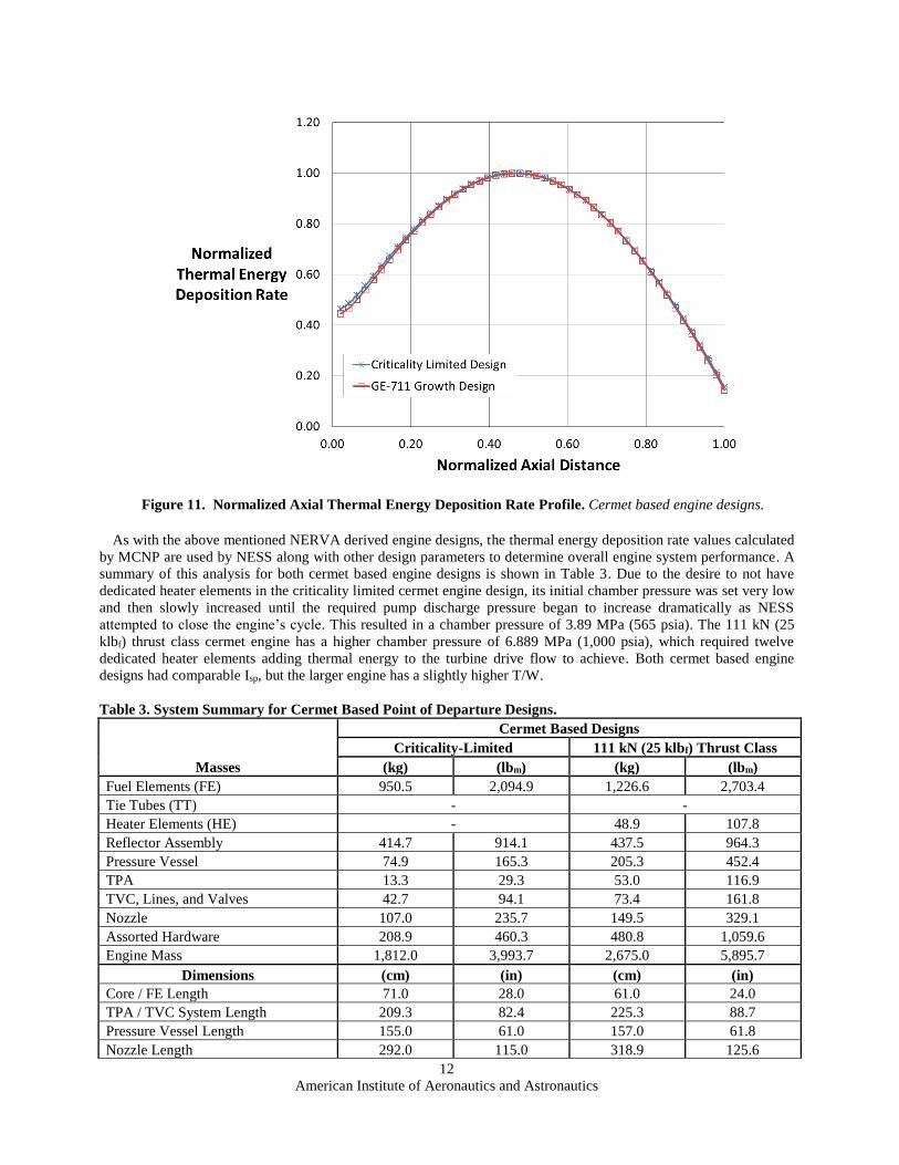
As with the above mentioned NERVA derived engine designs, the thermal energy deposition rate values calculated
by MCNP are used by NESS along with other design parameters to determine overall engine system performance. A
summary of this analysis for both cermet based engine designs is shown in Table 3. Due to the desire to not have
dedicated heater elements in the criticality limited cermet engine design, its initial chamber pressure was set very low
and then slowly increased until the required pump discharge pressure began to increase dramatically as NESS
attempted to close the engine’s cycle. This resulted in a chamber pressure of 3.89 MPa (565 psia). The 111 kN (25
klbf) thrust class cermet engine has a higher chamber pressure of 6.889 MPa (1,000 psia), which required twelve
dedicated heater elements adding thermal energy to the turbine drive flow to achieve. Both cermet based engine
designs had comparable Isp, but the larger engine has a slightly higher T/W.
Table 3. System Summary for Cermet Based Point of Departure Designs.
Cermet Based Designs
Criticality-Limited 111 kN (25 klbf) Thrust Class
Masses (kg) (lbm) (kg) (lbm)
Fuel Elements (FE) 950.5 2,094.9 1,226.6 2,703.4
Tie Tubes (TT) - -
Heater Elements (HE) - 48.9 107.8
Reflector Assembly 414.7 914.1 437.5 964.3
Pressure Vessel 74.9 165.3 205.3 452.4
TPA 13.3 29.3 53.0 116.9
TVC, Lines, and Valves 42.7 94.1 73.4 161.8
Nozzle 107.0 235.7 149.5 329.1
Assorted Hardware 208.9 460.3 480.8 1,059.6
Engine Mass 1,812.0 3,993.7 2,675.0 5,895.7
Dimensions (cm) (in) (cm) (in)
Core / FE Length 71.0 28.0 61.0 24.0
TPA / TVC System Length 209.3 82.4 225.3 88.7
Pressure Vessel Length 155.0 61.0 157.0 61.8
Nozzle Length 292.0 115.0 318.9 125.6
Figure 11. Normalized Axial Thermal Energy Deposition Rate Profile. Cermet based engine designs.

American Institute of Aeronautics and Astronautics
13
Nozzle Exit Diameter 172.3 67.8 188.2 74.1
Approx. Total Engine Length 656.3 258.4 701.2 276.0
Engine Parameters
No. Elements (FE/TT/HE) 163 / 0 / 0 313 / 0 / 12
Core Power Level 266 MWt 564 MWt
Chamber Pressure 3.89 MPa 565.0 psia 6.89 MPa 1,000.0 psia 235U Mass 238.5 kg 525.7 lbm 258.6 kg 570.0 lbm
Thrust 52.9 kN 11.9 klbf 111.6 kN 25.1 klbf
Thrust-to-Weight Ratio 2.98 4.26
Delivered Isp (s) 903 906
Table 4 shows a summary of the four engine designs presented here. The GE-711 based cermet engine design has
the highest T/W ratio of the four, but the 111 kN (25 klbf) thrust class NERVA derived design has slightly better Isp.
The criticality limited NERVA derived design has the lowest T/W and Isp of the group. The largest difference
between the two fuel types at both thrust classes is in the amount of 235U required. The criticality limited and larger
NERVA based engines require 27.5 kg (60.6 lbm) and 36.8 kg (81.1 lbm) respectively, whereas the cermet based
designs require almost eight times that amount with criticality limited design requiring 238.5 kg (525.6 lbm) and the
larger 111 kN (25lbf) class design needing 258.6 kg (570.0 lbm).
Table 4. Point of Departure NTR Engine Design Summary.
Fuel Type Composite Cermet
Fuel Element Geometry NERVA-Derived ANL-200 GE-711
Masses (kg) Criticality Limited 111 kN Class Criticality Limited 111 kN Class
Fuel Elements (FE) 207.7 612.8 950.5 1,226.6
Tie Tubes (TT) 231.0 313.7 - -
Heater Elements (HE) - - - 48.9
Reflector Assembly 717.7 1,141.6 414.7 437.5
Pressure Vessel 87.9 284.7 74.9 205.3
TPA 9.1 41.4 13.3 53.0
TVC, Lines, and Valves 38.2 85.8 42.7 73.4
Nozzle 81.0 149.8 107.0 149.5
Assorted Hardware 416.4 708.1 208.9 480.8
Engine Mass 1,789.0 3,338.0 1,812.0 2,675.0
Dimensions (cm)
Core / FE Length 89.0 132.0 71.0 61.0
TPA / TVC System Length 178.1 228.3 209.3 225.3
Pressure Vessel Length 207.1 320.9 155.0 157.0
Nozzle Length 233.7 320.2 292.0 318.9
Nozzle Exit Diameter 137.9 189.0 172.3 188.2
Approx. Total Engine Length 618.9 869.4 656.3 701.2
Engine Parameters
No. Elements (FE/TT/HE) 260 / 251 / 0 564 / 241 / 0 163 / 0 / 0 313 / 0 / 12
Core Power Level (MWt) 157 563 266 564
Chamber Pressure (MPa) 3.89 6.89 3.89 6.89 235U Mass (kg) 27.5 36.8 238.5 258.6
Thrust (kN) 33.4 111.2 52.9 111.6
Thrust (klbf) 7.52 25.18 11.9 25.1
Thrust-to-Weight Ratio 1.91 3.42 2.98 4.26
Delivered Isp (s) 894 909 903 906

American Institute of Aeronautics and Astronautics
14
V. Conclusion
Four revised point of departure NTR engines were designed and analyzed using an integrated MCNP and NESS
modeling scheme. All four engines, two NERVA derived and two cermet based, have thermodynamically closed
cycles at nominal chamber pressures. The SNRE derived fuel element and tie-tube pattern worked well for the larger
NERVA derived engine design, but a modified pattern was required for the criticality limited engine. The larger 111
kN (25 klbf) class cermet based engine required twelve dedicated heater elements to close its cycle, but the criticality
limited design did not require them to operate at a lower chamber pressure. Both cermet based designs had slightly
higher T/W ratios, but they required substantially more 235U.
Acknowledgments
The authors would like to thank Mark Stewart and Charles Sarmiento for many insightful technical discussions, as
well as, John Warren and Chris Moore (NASA Headquarters), and Mike Houts (MSFC) who supported this work
through the Advanced Exploration Systems Program and its Nuclear Cryogenic Propulsion Stage (NCPS) Project.
References 1. Stanley, Borowski K., McCurdy, David R., and Burke, Laura M., “The Nuclear Thermal Propulsion Stage (NTPS): A Key
Space Asset for Human Exploration and Commercial Missions to the Moon,” AIAA-2013-5465, July 2013. 2. Borowski, S., McGuire, M., and Beke, “Nuclear Thermal Rocket/Vehicle Design Options for Future NASA Missions to the
Moon and Mars,” NASA TM-1993-107071, 1993. 3. Watson, C.W., “Nuclear Rockets: High-Performance Propulsion for Mars,” Los Alamos National Laboratory Report LA-
12784-MS, May 1994. 4. C. Russell Joyner, Levack, Daniel, and Borowski, Stanley K., “Affordable Development of Nuclear Thermal Propulsion
Flight Demonstrator Based on Small Propulsion Concept that is Scalable to Human Missions,” Global Space Exploration
Conference, Washington D.C, 2012. 5. Koenig, D. R., "Experience Gained from the Space Nuclear Rocket Program (Rover)," Los Alamos National Lab., Report
LA-10062-H, Los Alamos, NM, May 1986. 6. Durham, F. P., “Nuclear Engine Definition Study Preliminary Report, Volume 1 – Engine Description,” Los Alamos
National Laboratory, Report LA-5044-MS Vol 1, Los Alamos, NM, Sept. 1972. 7. Durham. F. P., "Nuclear Engine Definition Study Preliminary Report, Volume 2- Supporting Studies," Los Alamos National
Lab., Rept. LA-5044-MS Vol 2, Los Alamos, NM, Sept 1972. 8. Borowski, S. K., McCurdy, D. R., and Packard, T. W., “7-Launch NTR Space Transportation System for NASA’s Mars
Design Reference Architecture (DRA) 5.0,” AIAA-2009-5308, August 2009. 9. Fittje, James E. and Schnitzler, Bruce G., “Cycle Analysis of a 200 MW Class Cermet based NTR Engine,” AIAA-2012-
3960, August 2012. 10. Schnitzler, Bruce G. and Borowski, Stanley K., “25,000-lbf Thrust Engine Options Based on the Small Nuclear Rocket
Engine Design,” AIAA-2009-5239, August 2009. 11. Taub, J. M., "A Review of Fuel Element Development for Nuclear Rocket Engines," Los Alamos National Lab., Rept. LA-
5931, Los Alamos, NM, June 1975. 12. Lyon, L. L., "Performance of (U,Zr)C-Graphite (Composite) and of (U,Zr)C (Carbide) Fuel Elements in the Nuclear
Furnace 1 Test Reactor," Los Alamos National Lab., Rept. LA-5398-MS, Los Alamos, NM, Sept 1973. 13. Burkes, Douglas E., Wachs, Daniel M., Werner, James E., and Howe, Steven D., “An Overview of Current and Part W-UO2
CERMET Fuel Fabrication Technology,” Idaho National Lab, Report INL/CON-07-12232, June 2007. 14. Fittje, James E. and Schnitzler, Bruce G., ”Analysis of NTR Engines Utilizing Prismatic Fuel Elements Derived from the
GE-710 Program,” AIAA 2013-4000, August 2013. 15. X-5 Monte Carlo Team, “MCNP – A General Monte Carlo N-Particle Transport Code, Version 5,” Los Alamos National
Laboratory, Report LA-UR-03-1987, Los Alamos, NM, April 2003. 16. Schnitzler, B., and Borowski, S., “Neutronics Models and Analysis of the Small Nuclear Rocket Engine (SNRE),” AIAA-
2007-5618, July 2007. 17. Fittje, James E., “Upgrades to the Nuclear Engine System Simulation (NESS) Code,” AIAA-2007-5620, July 2007 18. Fittje, James E. and Schnitzler, Bruce, G., “Evaluation of Recent Upgrades to the NESS (Nuclear Engine System Simulation
Code,” AIAA 2008-4951, July 2008. 19. Pelaccio, Schiel, and Petrosky, “Nuclear Engine System Simulation (NESS): Version 2.0,” NASA CR-191081, 1993. 20. Fittje, James E. and Schnitzler, Bruce, G., “Parametric Analysis of a 75 kN Thrust Class Composite Fuel Based NTR
Engine,” AIAA 2014-3431, July 2014. 21. Santiago, Jorge R., “Evolution of the RL-10 Liquid Rocket Engine for a New Upperstage Application,” AIAA 96-3013, July
1996. 22. Chen, Shu-cheng S., Veres, Joseph, P., and Fittje, James E., “Turbopump Design and Analysis Approach for Nuclear
Thermal Rockets,” NASA TM-2005-214004, 2005.