Revised on Mar 19, 2013. Accepted on Mar 28,...
35
Submitted on December 6, 2012 to Optical Engineering, special topic: Space Telescopes II Revised on Mar 19, 2013. Accepted on Mar 28, 2013 Development of Sensitive Long-wave Infrared Detector Arrays for Passively Cooled Space Missions Craig McMurtry 1 , [email protected] Donald Lee 2 , [email protected] James Beletic 2 , [email protected] Chi-Yi A. Chen 2 , [email protected] Richard T. Demers 2 , [email protected] Meghan Dorn 1 , [email protected] Dennis Edwall 2 , [email protected] Candice Bacon Fazar 1,3 , [email protected] William J. Forrest 1 , [email protected] Fengchuan Liu 4 , [email protected] A.Mainzer 4 , [email protected] Judith L. Pipher 1 , [email protected] Aristo Yulius 2 , [email protected] 1. Department of Physics and Astronomy, University of Rochester, Rochester NY 14627 2. Teledyne Imaging Sensors, 5212 Verdugo Way, Camarillo CA 90312 3. Roberts Wesleyan College, Department of Computer Science, Mathematics & Physics, 2301 Westside Drive Rochester, NY 14624 4. Jet Propulsion Laboratory, M/S 264-723 4800 Oak Grove Drive, California Institute of Technology, Pasadena CA 91109 1
Transcript of Revised on Mar 19, 2013. Accepted on Mar 28,...

Submitted on December 6, 2012 to Optical Engineering, special topic: Space Telescopes II
Revised on Mar 19, 2013. Accepted on Mar 28, 2013
Development of Sensitive Long-wave Infrared Detector Arrays for Passively Cooled Space Missions
Craig McMurtry1, [email protected]
Donald Lee2, [email protected]
James Beletic2, [email protected]
Chi-Yi A. Chen2, [email protected]
Richard T. Demers2, [email protected]
Meghan Dorn1, [email protected]
Dennis Edwall2, [email protected]
Candice Bacon Fazar1,3, [email protected]
William J. Forrest1, [email protected]
Fengchuan Liu4, [email protected]
A.Mainzer4, [email protected]
Judith L. Pipher1, [email protected]
Aristo Yulius2, [email protected]
1. Department of Physics and Astronomy, University of Rochester, Rochester NY 14627
2. Teledyne Imaging Sensors, 5212 Verdugo Way, Camarillo CA 90312
3. Roberts Wesleyan College, Department of Computer Science, Mathematics & Physics, 2301 Westside Drive Rochester, NY 14624
4. Jet Propulsion Laboratory, M/S 264-723 4800 Oak Grove Drive, California Institute of Technology, Pasadena CA 91109
1

Abstract
The Near Earth Object Camera (NEOCam) is a proposed infrared space mission designed to
discover and characterize most of the potentially hazardous asteroids larger than 140 m in
diameter that orbit near the Earth. NASA has funded technology development for NEOCam,
including the development of long wavelength infrared detector arrays that will have excellent
zodiacal background emission-limited performance at passively cooled focal plane temperatures.
Teledyne Imaging Sensors has developed and delivered for test at the University of Rochester the
first set of approximately 10 µm cutoff, 1024 1024 pixel HgCdTe detector arrays.
Measurements of these arrays show the development to be extremely promising: noise, dark
current, quantum efficiency and well depth goals have been met by this technology at focal plane
temperatures of 35-40K, readily attainable with passive cooling. The next set of arrays to be
developed will address changes suggested by the first set of deliverables.
Key words: Infrared, Detector Array, Long-wave, HgCdTe, Low Background, Passive Cooling,
Near Earth Object, Dark Current
2

Introduction: Requirements on Long-Wavelength Detector Arrays
The continued advancement of space-based astronomy/planetary science depends critically on
the development of improved detector array technology. For example, the recently-launched
Wide-field Infrared Survey Explorer (WISE)1 mission achieved point source sensitivities that
were improved by hundreds of times over the Infrared Astronomical Satellite (IRAS)2 which
launched in 1983, despite the fact that the IRAS telescope's primary mirror was larger than
WISE's (60 cm vs. 40 cm). Spatial resolution improved at 12 µm from ~0.5 arcmin for IRAS to
~6 arcsec for WISE. The major factor responsible for the advances in both sensitivity and spatial
resolution was the vast improvement in detector array technology, from 62 pixels for IRAS to
WISE's 4 million pixels. Many astronomical and planetary applications will benefit from the
construction of long-wave detector arrays with less demanding temperature requirements. One
such example is the Near-Earth Object Camera (NEOCam)3, a NASA Discovery-class mission
proposal designed to detect, discover and characterize a large fraction of the asteroids and comets
that most closely approach the Earth, the Near-Earth Objects (NEOs)4,5. NEOCam is a 0.5 m
space telescope with a single imaging instrument operating at two wavelength ranges: 4-5 µm
and 6-10 µm. Mid-wave 5 µm HgCdTe detector arrays for the James Webb Space Telescope
(JWST) are designed to perform well at 37K-46K and require no further development for
NEOCam. Our goal for the NEOCam mission has been to develop long-wave 10+ µm cutoff
arrays which function at 35-40K focal plane temperatures, with a preference for ~40K, for ease
of thermal design. Clearly, this LWIR array development has far greater future application than
just NEOCam. Other long-wave arrays used for astronomy (e.g. Si:As) require focal plane
temperatures ≤8K (e.g. Spitzer IRAC/IRS/MIPS, WISE, Akari).
3

The NEOCam design allows the mission to operate throughout its four year survey phase and
beyond without the need for life-limiting cryogens or costly and potentially unreliable cryo-
coolers. The Spitzer Space Telescope's focal planes6, 7, 8 have equilibrated to ~27 K now that its
liquid helium cryogen supply has been exhausted, demonstrating the efficacy of passive cooling
for a thermally well-designed space telescope. Throughout this warm mission Spitzer’s two mid-
wave InSb channels at 3.6 and 4.5 µm have performed with undiminished sensitivity, but require
focal plane temperatures not much higher than 30K. The WISE mission's 5.4 µm cutoff HgCdTe
arrays, manufactured by Teledyne Imaging Systems (TIS), operated at 32 K with dark currents
<5 e-/s/pixel9.
In 2003, in response to a NASA grant awarded to University of Rochester, TIS delivered
prototype 512 512 pixel HgCdTe arrays operating out to 10+ µm. They were shown to have
low dark current and low read noise for a moderately large fraction of the pixels10, 11, 12, 13. For
NEOCam, the fabrication of a mosaic of 1024 1024 HgCdTe arrays operating out to 10 µm is
required to enable its wide-field survey. TIS's HAWAII-1RG readout technology was selected
for NEOCam based on the readout family’s heritage in space- and ground-based astronomical
applications, including WISE14, the Hubble Space Telescope's Wide-Field Camera-315, and the
JWST16, 17. The HAWAII arrays have demonstrated the low power dissipation needed to support
passive cooling as well as the low noise performance required to detect faint, natural
background-limited astronomical sources and the narrow range of actual detector biases needed
for operation of longer-wave HgCdTe photodiodes with a Source-Follower per detector read-out
integrated circuit (ROIC). 4

The requirements for the NEOCam 10 µm arrays and comparison values for measurements of
the three arrays tested are summarized in Table 1. Of course, detailed exposition of those
measurements are found later in the text. The NEOCam telescope orbits the Earth-Sun L1
Lagrange point and can therefore achieve its required temperatures via passive cooling, so the
dominant background signal in this channel is due to thermal emission from our solar system's
zodiacal dust cloud. For observations on the solar system's ecliptic plane, the contribution from
the zodiacal background increases with decreasing solar elongation. The minimum estimated
background current for the 10 µm channel is ~300 electrons/s/pixel; therefore, dark current will
not be a significant contribution to overall system noise if it is < 200 electrons/s/pixel. Other
missions will, of course, have different requirements.
Table 1: Minimum NEOCam Requirements compared against Measured Properties of
Three Arrays
NEOCam
Requirement
H1RG-16885 H1RG-16886 H1RG-16887
Detector
Material
HgCdTe;
CdZnTe
substrate
removed
HgCdTe:
Substrate not
removed
HgCdTe:
Substrate not
removed
HgCdTe:
Substrate not
removed
Array format 1024x1024 By design By design By design
Cutoff
Wavelength
(µm)
10 10.6 9.9 9.9
Operating
temperature
35 - 40 35 35 35
5
(K)
Dark current
(e-/s/pixel)
<200 <200 <200 <200
CDS read noise
(e-)
50 22 22 22
RQE (%) >60 65 non-AR
coated, PEC
62 non-AR
coated, PEC
63 non-AR
coated, PEC
Well Depth (e-) >45k >55k >66k >75k
Pixel
operability (%)
>90 95* 94* 95*
*Pixel operability measured does not include RQE, but we estimate that spec. will easily
be satisfied once arrays AR coated. Also note that ~90% of the pixels show dark currents
< 1 e-/s/pixel.
In 2010, the NASA Discovery program awarded the NEOCam project technology funding to
support the development of megapixel HgCdTe arrays operating with low noise and low dark
current at wavelengths out to ~10 µm or beyond at focal plane temperatures which could be
achieved with passive cooling. The goals of the technology development program were fourfold:
1.) to increase the array format from 512 x 512 to 1024 x 1024 pixels; 2.) to deliver arrays with a
cutoff wavelength of 10+ µm with excellent operability; 3.) to meet well depth requirements; and
4.) to maintain the low dark current and read noise characteristics of shorter wavelength TIS
HgCdTe arrays. Meanwhile, NASA’s APRA program funded the testing, characterization and
optimization efforts of the University of Rochester team. We report in this paper the outstanding
results from the first phase of the LWIR detector development program.
Long-wave Detector Array Development
6

In order to meet NEOCam’s relatively low background long wavelength detector array
requirements, JPL and the University of Rochester (UR) have worked with TIS to build upon our
earlier progress in the development of low background 8.6, 9.2 and 10.3 µm cutoff HgCdTe
detector arrays. That earlier work included characterization of high dark current pixels
associated with various types of defects, and TIS has developed techniques to overcome these to
a large extent. In the last decade, TIS has demonstrated extremely sensitive 5 µm cutoff HgCdTe
detector arrays for WISE and JWST16,17, and many of the lessons learned in that development
were also applicable to long wavelength HgCdTe array development. TIS grew HgCdTe wafers
for the NEOCam detector array development program with two variations. Process Evaluation
Chip (PEC) testing showed three excellent wafers, and one 1024 1024 pixel detector array
from each wafer was hybridized to an H1RG readout integrated circuit (ROIC). The three arrays
were delivered to the University of Rochester for test in July 2012.
Prior development: Hg1-xCdxTe is a ternary compound, and the composition parameter x can be
varied to give the required long-wavelength cut-off. Shorter wave cut-off space astronomy
devices are easier to fabricate18, and astronomy caliber HgCdTe detector arrays for low
background applications have not been demonstrated beyond 5.4 µm, except for the progress
shown in our 2003 development program. The first generation prototype 512 512 36 µm
detector arrays from that program which were bonded to the H1RG ROIC10, 11, 12 showed
tremendous promise over the smaller format arrays developed in 200119, 12: however, they could
not fully meet the specifications for NEOCam and other space astronomy missions. TIS had in
place a well-developed long-wavelength program to produce arrays for high background
applications, but the low background long-wavelength development was not as advanced. The
7

circa 2003 devices delivered to the University of Rochester could only support very small
reverse biases, severely limiting well depth, even though the pixel nodal capacitance was quite
large for these relatively large pixels (~100 fF). Capacitive transimpedance amplifier (CTIA)
ROICs are often employed for long-wave HgCdTe: they are subject to glow and higher noise
because they are constantly powered up. With a CTIA ROIC a small detector bias could be
tolerated and thus maintain low dark current while maintaining a large charge capacity. However
we rejected this ROIC choice, partially because of high CTIA power dissipation (excessive
power dissipation for NEOCam requirements), and partially because there is unavoidable
Johnson noise from low resistance pixels.
Since 2003, Teledyne has made significant strides in improving the operability of its LWIR
(long-wave infrared) detectors operating under low backgrounds and temperatures through true
bandgap engineering, with independent control of both compositional profiling and doping to
achieve both optimal electrical and optical performance. This control exhibits a number of
advantages for LWIR low background space missions. The wide bandgap cap reduces the
susceptibility to surface-induced excess currents associated with variation in quality of
passivation. This helps to improve the reproducibility of the process as well as to minimize the
total detector dark current at low temperatures. Recent innovations by TIS in its MBE growth
process have led to an extremely low density of defects responsible for tunneling currents, the
primary source of excess detector current in reverse bias and the root cause for inoperability at
these wavelengths, backgrounds and operating temperatures. The 2012 LWIR detector arrays
delivered by TIS also benefited from process improvements that were made after detector
degradation was noticed by the JWST program20. The failure mode has been identified by TIS
8

and has been fully eliminated through process modifications. The improved approach has already
been implemented in most Teledyne FPA products for several years, with no reports of similar
failures. This new approach is presently being used on all new JWST flight parts, as well as for
NEOCam FPAs reported in this publication. Additionally, the NEOCam FPAs employ a
proprietary architecture that has thus far completely eliminated this failure mode.
In Table 2 we list the dark currents and well depths achieved from the 2001 and 2003
developments, as well as the spectacular performance of the 2012-produced arrays we report on
here (in bold). In this table we have emphasized dark current performance according to
NEOCam requirements. In discussion on the individual arrays it will be seen that far better dark
currents at slightly reduced operability are achieved.
University of Rochester utilizes a helium test dewar (see Fig. 3 of Forrest et al.21) with a ZnSe
window, a filter wheel containing cold (~4K) circular variable interference filters (4 - 8 and 8 –
14.3 µm, with bandwidths of 1.1% and 1.7%, respectively), several discrete filters, and a cold
dark slide for dark current and noise measurements. A Lyot stop of 67.6 µm diameter defines the
cold (~4K) aperture stop, and it is located 43.8 mm from the front surface of the array. The array
is heated to temperatures of 30-45K as monitored by a Lake Shore Cryotonics temperature
controller. A 77K can surrounds the helium can. We utilize an array controller, based on open-
source hardware from the Observatories of the Carnegie Institute of Washington (OCIW) design,
described by Moore et al.22. Quantum efficiency measurements are made through the dewar
window viewing a high emissivity black felt cloth at known temperature ~300K located below
the dewar window. A measurement of the black cloth cooled to 77K is subtracted from the
9

~300K measurement to isolate the in-band radiation. See Appendix A for further description and
validation of the technique.
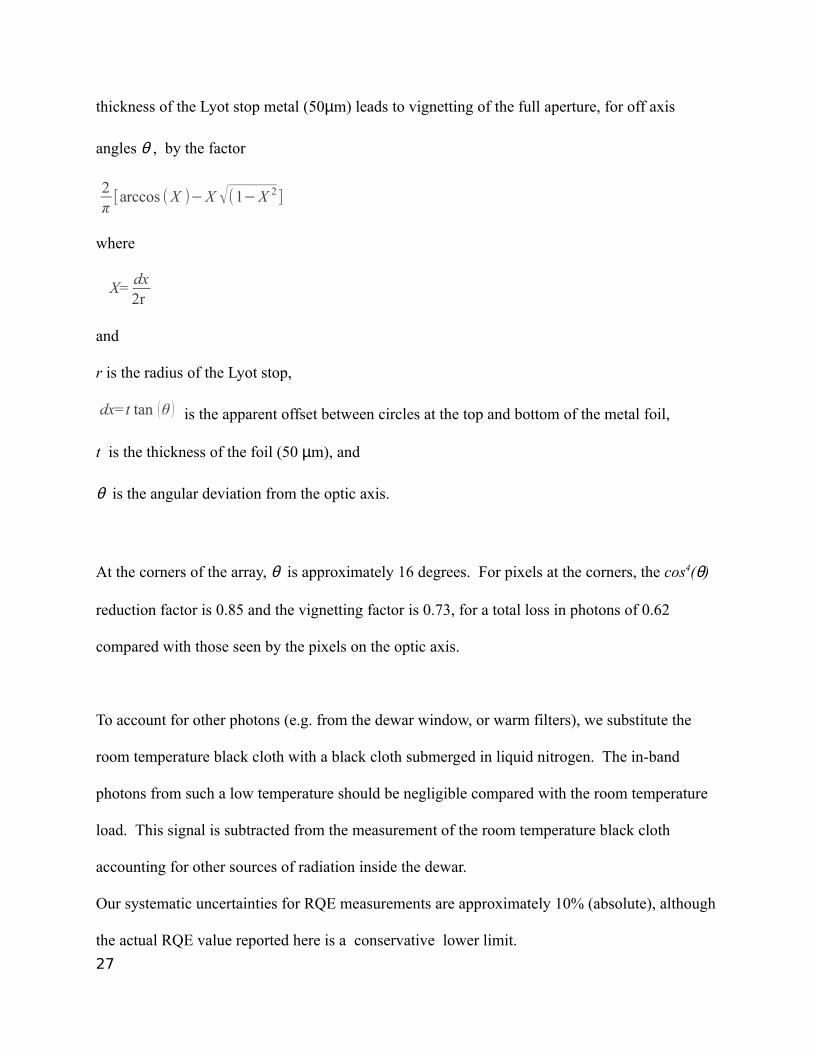
Table 2. Dark Currents and Well Depths for 10 µm Arrays
Format Pixel Pitch (µm)
λ cutoff
(µm)Year Produced
T Well Depth (e-)
Dark Current(e-/s)
Operability* Ref.
256 2 40 9.3 2001 30K >49k < 100 30%# 195122 36 9.3 2003 30K >25k
>50k
< 30
<30
75%
51%
11
5122 10.3 2003 30K >42k
>84k
< 100
<100
70%
29%
12
H1RG-
16885
10242
18 10.6 2012 30K (35K)
30K (35K)
42K
>42k
>55k
>50k
<200
<200
<200
97% (98%)
95% (95%)
94%
This
paper
H1RG-
16886
10242
18 9.9 2012 35Κ
35Κ
>39k
>66k
<200
<200
99%
94%
This
paper
H1RG-
16887
10242
18 9.9 2012 35K (40K)
35K (40K)
>47k
>75k
<200
<200
99% (98%)
95% (92%)
This
paper
*Operability is based ONLY on dark current for the well depth lower limit quoted. However, we
fully expect future AR-coated arrays to meet quantum efficiency specification as well. # This array was a test array with strips, comprised of differing diode geometries. The quoted
result is ONLY for the best strip (and this result informed future developments).
H1RG-16885: H1RG-16885 is a 10.6 µm cutoff array, constructed from one of the layers grown
by Teledyne which exhibited excellent Hall and defect characteristics, and which was measured
to have bulk doping density close to the target value as determined from the correlation of tun-
neling dark currents with doping density23. The array was bump-bonded to an H1RG ROIC, uti-
lizing proprietary bonding to avoid defects at the diode implant24, and with a design introducing
10

extra capacitance above that of the diode. For this first set of deliveries, the array was not epoxy
backfilled and not substrate removed
Nodal capacitance per pixel is required to calibrate quantum efficiency, well depth, dark current
and noise data, and is determined using the Signal vs. σ2 method25 and shown in Fig. 1 for
H1RG-16885. Averages for 70 regions of 50 50 pixel boxes are evaluated, and a typical set
plotted.
The interpixel capacitance (IPC) correction for H1RG-16885 is determined using very high dark
current pixels and the autocorrelation method26 . It is important to note that this device is not
epoxy backfilled: for use in space the devices must be epoxy back-filled, so that substrate
removal can take place. The epoxy backfill impacts the value for the IPC. For this array without
epoxy backfill, the average nearest-neighbor coupling parameter α is ~1.2% and with epoxy
backfill, rises to α ~ 1.6% using the hot pixel method. Thus the determined nodal capacitance
for H1RG-16885, which is not epoxy back-filled, must be reduced by the factor (1+8α), or
~10%26. The epoxy will increase this factor to ~13% with backfill. NEOCam arrays will be
epoxy backfilled and substrate removed: when that occurs, the capacitance and IPC will be re-
measured using several methods27. All of the measurements reported here were conducted on
arrays that were not epoxy back-filled unless noted. However, when using the autocorrelation
method, we obtain α ~ 2.0% for the case without epoxy backfill. The autocorrelation method
employs a uniform illumination at moderate integrated fluence levels, i.e. not dark backgrounds
as in the hot pixel method. The discrepancy (1.2% vs. 2.0%) that we see between the two
methods is consistent with the findings of other authors29, 30, 31.11

Process evaluation chip (PEC) data from TIS gave a responsive quantum efficiency of 65% at
100 mV of reverse bias and in the range from ~4 - 9 µm, and in addition provided a cutoff
wavelength of 10.6 µm at 30K. It is important to note that these first three arrays did not include
anti-reflection coating: thus 65% is very good (the theoretical maximum value possible is ~75%).
The University of Rochester has confirmed both the responsive quantum efficiency (at 8-9 µm)
and the half power cutoff wavelength with photometry of a black felt cloth of known
temperature, through a cold pinhole of known dimensions and distance from the array, through a
cold circular variable interference filter and a warm dewar window (Appendix A).
Well depth measurements are obtained by exposing the array to a low constant flux at 8.6 µm
monitoring the photo-signal (in mV) as a function of time to saturation. We define the well depth
as the signal above which the increase in signal per unit time is less than half its initial (i.e. low
signal) value. It should be noted that the H1RG ROIC adds a pedestal injection of 0-40 mV to
our applied reverse bias to give the actual reverse bias at the beginning of the integration. For
small dark currents, the pixel well depth equals the actual reverse bias for that pixel. Dark current
is of course, the most challenging requirement for space astronomy missions. One desires a dark
current per pixel less than the zodiacal emission signal per pixel. NEOCam’s dark current
requirements are not nearly as stringent as are those of JWST at 5 µm, where NIRSpec requires
<0.01 e-/s/pixel to be background emission limited. NEOCam, because of the broad bandwidth
of its long-wave channel, 6 – 10 µm (10 µm is near the zodiacal emission maximum) requires
only that dark current be <200 e-/s/pixel. The detector arrays we report on here easily meet
NEOCam dark current operability requirements at 200 e-/s/pixel and in fact meet much more
12

stringent requirements at marginally reduced operability. We have measured the dark current and
well depth of these devices at focal plane temperatures of 30K – 47K, and for a variety of
applied reverse biases. These are the first low background 10 µm HgCdTe arrays we have
encountered whose diodes can withstand substantial reverse biases. In Figs. 2 and 3 we give
examples of the dark current data for H1RG-16685. In Fig. 2, at an applied reverse bias of 200
mV, we provide a plot of well depth vs. dark current for a focal plane temperature of 30K. This
atypical graph is our diagnostic based on the properties of the 2003-era deliveries where many
very low dark current pixels turned out to also have nearly zero well depth! The concentration of
points centered at 0.1 e-/s/pixel and 240 mV well depth was our first indication that these 2012-
era arrays did not have that problem. A well depth of 160 mV corresponds to ~45,000 e-: most
of the array pixels are concentrated at a well depth exceeding the 200 mV applied bias (because
of the H1RG ROIC pedestal injection of 0-40 mV), and with very low dark current. Some pixels
have dark currents up to ~100 e-/s/pixel at that same well depth range as the concentration of
pixels. In addition, there are a small percentage of pixels with dark currents of >100 e-/s/pixel
which have debiased in the approximately 5s between pixel reset and the first pedestal sample,
reducing their well depths. Fig. 3 gives the cumulative histogram of the dark current for well
depths exceeding 180 mV and at a focal plane temperature of 35K (vertical axis gives the
percentage of 1016 x 1016 infrared active pixels). As can be seen, over 92% of the pixels have
dark currents ≤ 1 e-/s/pixel with a well depth > 180 mV (> 49,500 e-), a truly spectacular
achievement! At the NEOcam requirement of < 200 e-/s, the operability is 95%. Table 2
provides comparative data on the dark current operability at 30K, 35K and 42K for this array.
The two other arrays showed similar slight degradation with increasing temperature up to 42K.
13

Dark current operability vs. temperature was determined for focal plane temperatures of 30K –
47K under the NEOCam dark current requirements of <200 e-/s/pixel, and is presented in Fig. 4.
The ~10 µm arrays can be operated successfully to focal plane temperatures ~42K, a fact which
will positively impact NEOCam’s ultimate thermal design. In Fig. 5, we show an Arrhenius plot
of dark current vs. temperature for SCA H1RG-16885. This plot also illustrates the excellent
low dark current performance even at moderately high temperatures for the present generation of
long-wave HgCdTe detector arrays. These data are the dark currents for the best performing
pixels, i.e. those pixels with the lowest dark current and 240 mV of actual reverse detector bias,
which is also equivalent to 240 mV of well depth. The data represented by filled circles were
taken at a stable, constant temperature, which allows us to accurately measure the lowest dark
currents achieved. The data represented by squares were taken while the temperature was
allowed to slowly increase, which allows us to accurately measure the higher levels of dark
current at those higher temperatures. The lines plotted are the models that were fit to our data. At
temperatures above 42K, diffusion dark current is dominant, while generation-recombination
dark current is the majority component over the range of 36K to 42K. Below 36K, there is a
contribution to the apparent dark current that does not vary with either temperature or applied
detector bias, but instead behaves as if it were due to actual photons, e.g. a light leak or a glow
from the unit cells of the ROIC at the 0.16 e-/s/pixel level. We believe that the light leak
explanation is most probable. We have not fully investigated the source of these photons since a
dark current of 0.16 e-/s/pixel is a full 3 orders of magnitude better than the requirements for
NEOCam. Further, since we saw no variation in dark current with applied detector bias, then
any trap-to-band or band-to-band tunneling dark currents must be at least an order of magnitude
lower, i.e. <0.01 e-/s/pixel, at 30K for the given 240 mV detector bias shown in Fig. 5. It is
14

extremely gratifying that these pixels have a negligible tunneling component to the dark current,
unlike earlier generations of LWIR devices19.
Overall pixel operability of the array includes not only dark current, but also noise and quantum
efficiency. While we did not calculate overall operability, we next describe measurements of the
noise and responsive quantum efficiency. Noise is determined from a data set consisting of 25
independent dark images of 16 sample-up-the-ramp (SUTR) frames. From this we create 25
Fowler-1, 25 Fowler-4, and 25 Fowler-8 images25 from which the RMS read noise per pixel is
calculated. Cosmic ray hits and Random Telegraph noise are removed through iterative 4σ
clipping. Data were obtained at several focal plane temperatures. A histogram of 35K Fowler-1
noise for H1RG-16885 is shown in Fig. 6: the median noise is 21.9 e- and reduces with
increased number of samples. At 30K focal plane temperature, the median Fowler-1 noise is
slightly higher, 24.0 e-, probably because the H1RG was designed for higher temperature
operation. The NEOCam noise requirement is < 50 e-. All pixels with dark current < 200 e-/s
satisfy this and are operable on this count.
An image under flat field illumination through a cold Lyot stop (300K black felt cloth) is shown
in Fig. 7, corrected for two effects: the geometry and various corrections to produce a “flat field”
image are discussed in Appendix A. A cos4(θ) drop off in intensity from the optic axis has been
removed, as well as vignetting attributed to the fact that our Lyot stop aperture of 67.6 µm has a
thickness comparable in size to the diameter. The implied vignetting factor from the center (1.0)
to the corner is 0.62 (see Appendix A). A residual gradient in the image remains, however, and
some remaining interference from the cold circular variable filter wheel centered at 5.6 µm.
Implicit in our flat field and quantum efficiency estimates is the assumption that the black cloth
is an effective blackbody. While this irradiance is not cavity radiation, our experience on Spitzer 15

IRAC has shown that the assumption is valid: in-flight calibration against known standard stars
yielded the expected response as measured in this manner in our lab.
Responsive quantum efficiency (RQE) is calculated from these flat-field data. RQE as a
function of wavelength (from 8-10 µm) in the central 50 50 pixels2 was found to verify within
uncertainties both the RQE between 8 and 9 µm, and the cutoff wavelength as determined by TIS
PEC results via a Fourier transform infrared (FTIR) spectrometer, for the wafer from which
H1RG-16885 was constructed. We did not calculate total pixel operability including individual
RQE/pixel, because the device was not AR-coated, nor was the response perfectly “flat” due to
illumination that was not properly uniform across the entire array. The NEOCam specification
(for an AR-coated array) is > 60%.
H1RG-16886: We obtained similar data on this device, an array with a 10.1 µm cutoff
wavelength at 30K, and responsive quantum efficiency (RQE) ~62% as measured by TIS from 4-
9 µm. The responsive RQE value between 8 – 9 µm in our tests is ~58% (excellent agreement
within uncertainties), but the cutoff wavelength appears to be ~9.9 µm at 35K focal plane
temperature (see Fig. 8) as compared with TIS determined 10.15 µm using a FTIR spectrometer
at 30K, which can be explained by the variation of the band gap energy with temperature28. The
dark current operability for this array exceeds that of H1RG-16885 as can be seen from Table 2,
and the cumulative dark current distribution for 35K focal plane temperature, >180 mV well
depth is shown in Fig. 9. Here the applied bias is 250 mV rather than 200 mV as displayed in
Fig. 3 for H1RG-16885, and the performance is relatively degraded by this 25% higher bias.
16

Following test, H1RG-16886 was sent back to TIS, and the area between the detector array
material and the multiplexer was half back-filled with epoxy. The IPC nearest neighbor coupling
α was measured in the epoxied area using the hot pixel method and compared against that
determined in the non-epoxied area. In Fig. 10 is a histogram showing the peak values
determined for the two areas, with 1.2% corresponding to the non-epoxied area and 1.6% to the
epoxied area.
H1RG-16887: We obtained similar data on this device, an array with a 9.8 µm cutoff
wavelength, and QE ~63% measured by TIS from 4-9 µm. As before, we roughly confirm these
values in our tests. The dark current operability for this array is similar to those of H1RG-16885
and H1RG-16886 as can be seen from Table 2, and the cumulative dark current distribution for
35K focal plane temperature, and >180 mV well depth is shown in Fig. 11. Again, the higher
detector bias of 250 mV slightly degrades the dark current performance relative to that for the
200 mV bias employed for H1RG-16885.
Summary
TIS has produced and delivered three superb low background long-wave arrays to meet
NEOCam specifications. Testing of the three arrays is reported on here with top-level results
shown in Table 1. Future work will include enhanced IPC estimation, substrate removal,
antireflection coating and radiation testing.
Acknowledgements: A. Mainzer and the JPL group acknowledge support from NASA’s
Discovery program to fund development and acquisition of long wave low background arrays
17

from Teledyne, and J. Pipher and the Rochester group acknowledge support by NASA APRA
grant NNX12AF39G for test and optimization of those arrays.
References
1. Wright, Edward L.; Eisenhardt, Peter R. M.; Mainzer, A. K.; Ressler, Michael E.;
Cutri, Roc M.; Jarrett, Thomas; Kirkpatrick, J. Davy; Padgett, Deborah; McMillan,
Robert S.; Skrutskie, Michael; Stanford, S. A.; Cohen, Martin; Walker, Russell G.;
Mather, John C.; Leisawitz, David; Gautier, Thomas N., III; McLean, Ian; Benford,
Dominic; Lonsdale, Carol J.; Blain, Andrew; Mendez, Bryan; Irace, William R.;
Duval, Valerie; Liu, Fengchuan; Royer, Don; Heinrichsen, Ingolf; Howard, Joan;
Shannon, Mark; Kendall, Martha; Walsh, Amy L.; Larsen, Mark; Cardon, Joel G.;
Schick, Scott; Schwalm, Mark; Abid, Mohamed; Fabinsky, Beth; Naes, Larry; Tsai,
Chao-Wei. "The Wide-field Infrared Survey Explorer (WISE): Mission Description
and Initial On-orbit Performance" 2010 AJ 140, 1868
2. Beichman, C. A.; Neugebauer, G.; Habing, H. J.; Clegg, P. E.; Chester, Thomas J.
"Infrared astronomical satellite (IRAS) catalogs and atlases. Volume 1: Explanatory
supplement" 1988 IRAS Explanatory Supplement.
http://adsabs.harvard.edu/abs/1988iras....1.....B
3. Mainzer, A. "NEOCam: The Near-Earth Object Camera" Bulletin of the American
Astronomical Society, Vol. 38, p.568. 2006 DPS 38, 4509
4. Mainzer, A.; Grav, T.; Masiero, J.; Bauer, J.; McMillan, R. S.; Giorgini, J.; Spahr, T.;
Cutri, R. M.; Tholen, D. J.; Jedicke, R.; Walker, R.; Wright, E.; Nugent, C. R.,
18

"Characterizing Subpopulations within the near-Earth Objects with NEOWISE:
Preliminary Results", ApJ, 752, 110, 2012
5. Mainzer, A.; Grav, T.; Bauer, J.; Masiero, J.; McMillan, R. S.; Cutri, R. M.; Walker,
R.; Wright, E.; Eisenhardt, P.; Tholen, D. J.; Spahr, T.; Jedicke, R.; Denneau, L.;
DeBaun, E.; Elsbury, D.; Gautier, T.; Gomillion, S.; Hand, E.; Mo, W.; Watkins, J.;
Wilkins, A.; Bryngelson, G. L.; Del Pino Molina, A.; Desai, S.; G\'omez Camus, M.;
Hidalgo, S. L.; Konstantopoulos, I.; Larsen, J. A.; Maleszewski, C.; Malkan, M. A.;
Mauduit, J.-C.; Mullan, B. L.; Olszewski, E. W.; Pforr, J.; Saro, A.; Scotti, J. V.;
Wasserman, L. H., "NEOWISE Observations of Near-Earth Objects: Preliminary
Results", ApJ, 743, 156, 2011
6. Werner, M. W.; Roellig, T. L.; Low, F. J.; Rieke, G. H.; Rieke, M.; Hoffmann, W. F.;
Young, E.; Houck, J. R.; Brandl, B.; Fazio, G. G.; Hora, J. L.; Gehrz, R. D.; Helou,
G.; Soifer, B. T.; Stauffer, J.; Keene, J.; Eisenhardt, P.; Gallagher, D.; Gautier, T. N.;
Irace, W.; Lawrence, C. R.; Simmons, L.; Van Cleve, J. E.; Jura, M.; Wright, E. L.;
Cruikshank, D. P. "The Spitzer Space Telescope Mission" 2004 ApJS 154, 1
7. McMurtry, C.W; Pipher, J..; and Forrest, W.. "Spitzer Space telescope: dark current
and total noise prediction for InSb Detector Arrays in the Infrared Array Camera
(IRAC) for the post-cryogen era" Proc. SPIE 6265, 08-1
8. Mahoney, William A.; Garcia, Lisa J.; Hunt, Joseph, Jr.; McElroy, Douglas B.;
Mannings, Vince G.; Mittman, David S.; O'Linger, Joann C.; Sarrel, Marc; Scire,
Elena “Spitzer warm mission transition and operations” 2010 Proc. SPIE, 7737,
77371W
19

9. Cutri, R. M.; Wright, E. L.; Conrow, T.; Bauer, J.; Benford, D.; Brandenburg, H.;
Dailey, J.; Eisenhardt, P. R. M.; Evans, T.; Fajardo-Acosta, S.; Fowler, J.; Gelino, C.;
Grillmair, C.; Harbut, M.; Hoffman, D.; Jarrett, T.; Kirkpatrick, J. D.; Leisawitz, D.;
Liu, W.; Mainzer, A.; Marsh, K.; Masci, F.; McCallon, H.; Padgett, D.; Ressler, M. E.;
Royer, D.; Skrutskie, M. F.; Stanford, S. A.; Wyatt, P. L.; Tholen, D.; Tsai, C. W.;
Wachter, S.; Wheelock, S. L.; Yan, L.; Alles, R.; Beck, R.; Grav, T.; Masiero, J.;
McCollum, B.; McGehee, P.; Papin, M.; Wittman, M. "Explanatory Supplement to the
WISE All-Sky Data Release Products" 2012 WISE Explanatory Supplement
http://wise2.ipac.caltech.edu/docs/release/allsky/expsup/index.html
10. Bacon, Candice M.; McMurtry, Craig W.; Pipher, Judith L.; Forrest, William J.;
Garnett, James D.; Lee, Donald; Edwall, Dennis D.; “Characterization of Rockwell
Scientific LWIR HgCdTe Detector Arrays”2004a Proc. SPIE 5167, 313B
11. Bacon, Candice M.; McMurtry, Craig W.; Pipher, Judith L.; Forrest, William J.;
Garnett, James D.; Lee Donald; Edwall, Dennis D. “Further characterization of
Rockwell Scientific LWIR HgCdTe detector arrays”, 2004b Proc. SPIE 5563, 35B
12. Bacon, Candice M.;McMurtry, Craig W.; Pipher, Judith L.; Mainzer, Amanda; Forrest
, William,J. “Effect of dislocations on dark current in LWIR HgCdTe photodiodes”,
2010, Proc. SPIE 7742, 77421U-77421U-9
13. Bacon, Candice M. “Development of long wave infrared detectors for space
astronomy” , 2006, PhD Thesis , University of Rochester
14. Mainzer, A.; Larsen, Mark; Stapelbroek, Maryn G.; Hogue, Henry; Garnett, James;
Zandian, Majid; Mattson, Reed; Masterjohn, Stacy; Livingston, John; Lingner,
20

Nicole; Alster, Natali; Ressler, Michael; Masci, Frank. "Characterization of flight
detector arrays for the wide-field infrared survey explorer" 2008 SPIE 7021, 27
15. Baggett, S. M.; Hill, R. J.; Kimble, R. A.; MacKenty, J. W.; Waczynski, A.;
Bushouse, H. A.; Boehm, N.; Bond, H. E.; Brown, T. M.; Collins, N. R.; Delo, G.;
Dressel, L.; Foltz, R.; Hartig, G.; Hilbert, B.; Kan, E.; Kim-Quijano, J.; Malumuth,
E.; Martel, A.; McCullough, P.; Petro, L.; Robberto, M.; Wen, Y., “The Wide-Field
Camera 3 detectors”, 2008 Proc. SPIE 7021, 50B.
16.Smith, Erin C.; Rauscher, Bernard J.; Alexander, David; Clemons, Brian L.; Engler,
Chuck; Garrison, Matthew B.; Hill, Robert J.; Johnson, Thomas; Lindler, Don J.;
Manthripragada, Sridhar S.; Marshall, Cheryl; Mott, Brent; Parr, Thomas M.; Roher,
Wayne D.; Shakoorzadeh, Kamdin B.; Schnurr, Richard; Waczynski, Augustyn; Wen,
Yiting; Wilson, Donna; Loose, Markus; Bagnasco, Giorgio; Böker, Torsten; de
Marchi, Guido; Ferruit, Pierre; Jakobsen, Peter; Strada, Paolo “JWST near infrared
detectors: latest test results” 2009 Proc. SPIE, 7419, 741907
17.Greene, Thomas; Beichman, Charles; Gully-Santiago, Michael; Jaffe, Daniel; Kelly,
Douglas; Krist, John; Rieke, Marcia; Smith, Eric H. “NIRCam: development and
testing of the JWST near-infrared camera “ 2010 Proc. SPIE, 7731, 77310C
18.Phillips, J., Edwall, D., Lee, D. and Arias, J. 2001, J. Vac. Sci. Tech. B. 19, 1580
19. Bacon, Candice M.; Pipher, Judith L.; Forrest, William J.; McMurtry, Craig M.;
Garnett, James D., “Diode Characterization of Rockwell LWIR HgCdTe Detector
Arrays” 2003 Proc. SPIE 4850, 927
21

20. Rauscher, B. J.; Stahle, C.; Hill, R. J.; Greenhouse, M.; Beletic, J.; Babu, S.; Blake,
P.; Cleveland, K.; Cofie, E.; Eegholm, B.; Engelbracht, C. W.; Hall, D. N. B.;
Hoffman, A.; Jeffers, B.; Jhabvala, C.; Kimble, R. A.; Kohn, S.; Kopp, R.; Lee, D.;
Leidecker, H.; Lindler, D.; McMurray, R. E.; Misselt, K.; Mott, D. B.; Ohl, R.;
Pipher, J. L.; Piquette, E.; Polis, D.; Pontius, J.; Rieke, M.; Smith, R.; Tennant, W. E.;
Wang, L.; Wen, Y.; Willmer, C. N. A.; Zandian, M.; "Commentary: JWST near-
infrared detector degradation - finding the problem, fixing the problem, and moving
forward", AIP Advances, 2, 021901, 2012
21. Forrest, W. J.; Moneti, A.; Woodward, C. E.; Pipher, J. L.; Hoffman, A. “The New
Near Infrared Array Camera at the University of Rochester” 1985 PASP 97, 183.
22. Moore, A.C., Ninkov, Z. Burley, G., Forrest, W.J., McMurtry, C.M. and Avery, L.
"Operation and test of hybridized silicon p-i-n arrays using open-source array control
hardware and software" 2003 Proc. SPIE 5017, 240
23. Wu, J., Forrest, W.J., Pipher, J.L., Lum, N., Hoffman, A. 1997 Rev. Sci.Inst. 68, 3566
24.Carmody, M., Lee, D., Zandian, M., Phillips, J., Arias, J. 1999 Air Force Document,
contract F33615-99-C-5432
25.Mortara, L. and Fowler, A. “Evaluations of Charge-Coupled Device for
Astronomical Use” 1981 Proc. SPIE 290, 28M
26.Moore, A.C., Ninkov, Z. and Forrest, W.J. “Interpixel capacitance in nondestructive
focal plane arrays” 2004 Proc. SPIE 5167, 204M
22

27. Fox, O., Waczynskic, A., Wen, Yiting, Foltz, R.E., Hill, R.J., Kimble, R., Malumuth,
E., and Rauscher, R. The 55Fe X-ray Energy Response of Mercury Cadmium
Telluride Near-Infrared Detector Arrays 2008 Proc. SPIE 7012, 702123-1
28. Hansen, G. L., Schmit, J.L. , and Casselman, T.N., “Energy gap versus alloy
composition and temperature in Hg1–x CdxTe,” J. Appl. Phys. 53, 7099–7101 (1982).
29. Cheng, L. “Interpixel capacitive coupling,” MS Thesis, Center for Imaging Science
—Rochester Institute of Technology, 2009
30. Giardino, Giovanna; Sirianni, Marco; Birkmann, Stephan M.; Rauscher, Bernard J.;
Lindler, Don; Böker, Torsten; Ferruit, Pierre; De Marchi, Guido; Stuhlinger, Martin;
Jensen, Peter; Strada, Paolo, “Noise properties and signal-dependent interpixel
crosstalk of the detectors of the Near-Infrared Spectrograph of the James Webb Space
Telescope”, 2013 Opt. Eng., 52 (3), 034001
31. Dudik, R. P.; Jordan, M. E.; Dorland, B. N.; Veillette, D.; Waczynski, A.; Lane, B. F.;
Loose, M.; Kan, E.; Waterman, J.; Rollins, C.; Pravdo, S., “Interpixel crosstalk in
Teledyne Imaging Sensors H4RG-10 detectors”, 2012 Applied Optics, 51, 2877D
23

Figure Captions
Fig. 1. Capacitance per pixel determined for H1RG-16885, with no IPC (interpixel capacitance)
correction applied.
Fig. 2. Well depth vs. dark current for H1RG-16885 at a focal plane temperature of 30K, and 200
mV applied reverse bias. As noted in text, this graph is a diagnostic, illustrating that the
preponderance of pixels have excellent well depth and very low dark current, and are centered
around 0.1 e-/s and 230mV. Even for slightly higher dark current, there is only a small
percentage of pixels that decrease in well depth because of debias between the pixel reset and the
pedestal (first sample) measurement.
Fig. 3. Histogram of the cumulative dark current for H1RG-16885 for well depths > 180 mV for
200 mV reverse bias at a focal plane temperature of 35K. Only infrared active pixels are
included.
Fig. 4. Operability vs. Focal Plane temperature for H1RG-16885.
Fig. 5. An Arrhenius plot of dark current per pixel versus inverse temperature for an actual well
depth (reverse detector bias) of 240 mV.
Fig. 6. Histogram of Fowler-1 noise/pixel for H1RG-16885. Fowler-1 sampling is equivalent to
correlated double sampling.
Fig. 7. Flat-field illumination of H1-RG-16885 through a circular variable filter wheel centered
at 5.6 µm. The dark spots with bright halos are diffraction/shadows from dust specks suspended
800 µm in front of the detector surface, demonstrating the good imaging properties of the array.24

Fig. 8. Responsive quantum efficiency as a function of wavelength for H1RG-16886 at a focal
plane temperature of 35K.
Fig. 9. Histogram of the cumulative dark current for H1RG-16886 for well depths > 180 mV for
250 mV reverse bias at a focal plane temperature of 35K. Only infrared active pixels are
included.
Fig. 10. Histogram of IPC nearest neighbor coupling parameter α obtained for H1RG-16776 for
the half of the array that was not backfilled with epoxy (peak 1.2%) and for the half of the array
that was (1.6%).
Fig. 11. Histogram of the cumulative dark current for H1RG-16887 for well depths > 180 mV for
250 mV reverse bias at a focal plane temperature of 35K. Only infrared active pixels are
included.
Table Captions:
Table 1: Minimum NEOCam Requirements against Measured Properties of Three Arrays.
Table 2: Dark Currents and Well Depths for 10 µm Arrays
25

Appendix A: Flat Field Measurement and Corrections
We use radiation flux from a room temperature blackbody to measure the quantum efficiency of
the HgCdTe photodiode pixels. The blackbody is a black felt cloth, with temperature measured
to 0.1 C. To account for the cloth emissivity being less than 1.00, we rely on the temperatures of
all the other objects in the room being at about the same temperature as the black cloth. The
wavelengths of the incident photons are defined by a 4.2K temperature interference filter
approximately 45 mm from the detector's surface. The basic geometry of our setup is given in
Fig. 3 of Forrest et al.21. For lab measurements, the reimaging lens in that figure is removed and
the black cloth is placed at the position of the "Image of Celestial Object". The technique of
imaging black felt was utilized in our tests of Spitzer InSb detector arrays. Once these arrays
were flown, and calibrated with measurements of several stars, the response in the IRAC bands
centered at 3.6 and 4.5 µm, proved to be in good agreement with our lab estimates of the RQE.
Furthermore, the TIS measured RQE of the PECs were within 6% of our measurements: the TIS
measurements employed a NIST-calibrated source.
To limit the stray radiation in the cold "inner sanctum" housing the detector, we use a Lyot stop
defined by a 67.6 µm diameter hole through a 50 µm thick metal foil. For pixels on the optic
axis, the pixel area is taken to be that of an 18 µm square. The solid angle is given by the
effective optical distance between the detector's back surface and the 67 µm Lyot stop. The
physical distance is 44.6 mm. The 0.8 mm thick CdZnTe substrate acts to reduce that distance
by 1.3 mm. At an angle θ off axis, the effective pixel area is reduced by the projection factor
cos(θ) while the effective solid angle is reduced by the factor cos3(θ). In addition, the finite
26
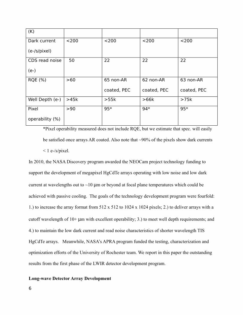
thickness of the Lyot stop metal (50µm) leads to vignetting of the full aperture, for off axis
angles θ , by the factor
2π
[arccos (X )−X √(1−X 2 ]
where
X=
dx2r
and
r is the radius of the Lyot stop,
dx=t tan (θ ) is the apparent offset between circles at the top and bottom of the metal foil,
t is the thickness of the foil (50 µm), and
θ is the angular deviation from the optic axis.
At the corners of the array, θ is approximately 16 degrees. For pixels at the corners, the cos4(θ)
reduction factor is 0.85 and the vignetting factor is 0.73, for a total loss in photons of 0.62
compared with those seen by the pixels on the optic axis.
To account for other photons (e.g. from the dewar window, or warm filters), we substitute the
room temperature black cloth with a black cloth submerged in liquid nitrogen. The in-band
photons from such a low temperature should be negligible compared with the room temperature
load. This signal is subtracted from the measurement of the room temperature black cloth
accounting for other sources of radiation inside the dewar.
Our systematic uncertainties for RQE measurements are approximately 10% (absolute), although
the actual RQE value reported here is a conservative lower limit.
27

Fig. 1
28

Fig. 2
Fig. 3
29

Fig. 4
30

Fig. 5
31

Fig. 6
32

Fig. 7
33

Fig. 8
Fig. 9
34

Fig. 10
Fig. 11
35


![arXiv:1103.0630v1 [astro-ph.CO] 3 Mar 2011myriam/publications/Cavagnolo-RBS797-2011.pdfarXiv:1103.0630v1 [astro-ph.CO] 3 Mar 2011 ACCEPTED TO APJ Preprint typeset using LATEX style](https://static.fdocuments.in/doc/165x107/5f66a5ec52c3cb72ea23b686/arxiv11030630v1-astro-phco-3-mar-myriampublicationscavagnolo-rbs797-2011pdf.jpg)