Smart Snacking Lauren Boyd, Nova Elwood, Sarah Glasser, Alex Taraghi, Hallie Hopkins.

ARTICLE IN PRESS
Mechanical Systemsand
Signal Processing
0888-3270/$ - se
doi:10.1016/j.ym
�CorrespondE-mail addr
Mechanical Systems and Signal Processing 20 (2006) 255–281
www.elsevier.com/locate/jnlabr/ymssp
Review
Smart structure dynamics
S. Hurlebausa,�, L. Gaulb
aZachry Department of Civil Engineering, Texas A&M University, 3136 TAMU, College Station, TX, 77843-3136, USAbUniversity of Stuttgart, Institute of Applied and Experimental Mechanics, Pfaffenwaldring 9, 70550 Stuttgart, Germany
Received 31 May 2005; received in revised form 16 August 2005; accepted 22 August 2005
Available online 12 October 2005
Abstract
This paper gives an overview of research in the area of smart structure dynamics. A general description of smart material
systems is given. Particular focus is given to the following fields of application: semi-passive concepts, energy harvesting,
semi-active concepts, active vibration control, and active structural acoustic control. The use of smart structures in
structural health monitoring applications is also considered.
r 2005 Elsevier Ltd. All rights reserved.
Keywords: Active vibration control (AVC); Active noise control (ANC); Shunted piezoelectricity; Energy harvesting; Semi-active
damping; Structural health monitoring (SHM)
Contents
1. Introduction . . . . . . . . . . . . . . . . . . . . . . . . . . . . . . . . . . . . . . . . . . . . . . . . . . . . . . . . . . . . . . . . . . . . . . 256
2. Modelling of smart materials and structures. . . . . . . . . . . . . . . . . . . . . . . . . . . . . . . . . . . . . . . . . . . . . . . . 256
2.1. Piezoelectric material . . . . . . . . . . . . . . . . . . . . . . . . . . . . . . . . . . . . . . . . . . . . . . . . . . . . . . . . . . . 256
2.2. Shape Memory Alloy . . . . . . . . . . . . . . . . . . . . . . . . . . . . . . . . . . . . . . . . . . . . . . . . . . . . . . . . . . . 257
2.3. Chemomechanical materials . . . . . . . . . . . . . . . . . . . . . . . . . . . . . . . . . . . . . . . . . . . . . . . . . . . . . . 259
3. Semi-passive damping . . . . . . . . . . . . . . . . . . . . . . . . . . . . . . . . . . . . . . . . . . . . . . . . . . . . . . . . . . . . . . . 260
4. Energy harvesting . . . . . . . . . . . . . . . . . . . . . . . . . . . . . . . . . . . . . . . . . . . . . . . . . . . . . . . . . . . . . . . . . . 261
5. Semi-active concepts . . . . . . . . . . . . . . . . . . . . . . . . . . . . . . . . . . . . . . . . . . . . . . . . . . . . . . . . . . . . . . . . 262
5.1. Control of semi-active viscoelastic dampers . . . . . . . . . . . . . . . . . . . . . . . . . . . . . . . . . . . . . . . . . . . 263
5.2. Control of semi-active joint connections . . . . . . . . . . . . . . . . . . . . . . . . . . . . . . . . . . . . . . . . . . . . . . 263
6. Active vibration control . . . . . . . . . . . . . . . . . . . . . . . . . . . . . . . . . . . . . . . . . . . . . . . . . . . . . . . . . . . . . . 265
7. Active noise control/active structural-acoustic control . . . . . . . . . . . . . . . . . . . . . . . . . . . . . . . . . . . . . . . . . 267
8. Active vibration isolation . . . . . . . . . . . . . . . . . . . . . . . . . . . . . . . . . . . . . . . . . . . . . . . . . . . . . . . . . . . . . 269
9. Structural health monitoring (SHM) . . . . . . . . . . . . . . . . . . . . . . . . . . . . . . . . . . . . . . . . . . . . . . . . . . . . . 270
9.1. Passive sensing diagnostics . . . . . . . . . . . . . . . . . . . . . . . . . . . . . . . . . . . . . . . . . . . . . . . . . . . . . . . 271
9.2. Active sensing diagnostics . . . . . . . . . . . . . . . . . . . . . . . . . . . . . . . . . . . . . . . . . . . . . . . . . . . . . . . . 272
9.3. Self-healing–self-repairing . . . . . . . . . . . . . . . . . . . . . . . . . . . . . . . . . . . . . . . . . . . . . . . . . . . . . . . . 276
e front matter r 2005 Elsevier Ltd. All rights reserved.
ssp.2005.08.025
ing author.
esses: [email protected] (S. Hurlebaus), [email protected] (L. Gaul).

ARTICLE IN PRESSS. Hurlebaus, L. Gaul / Mechanical Systems and Signal Processing 20 (2006) 255–281256
10. Conclusions. . . . . . . . . . . . . . . . . . . . . . . . . . . . . . . . . . . . . . . . . . . . . . . . . . . . . . . . . . . . . . . . . . . . . . . 277
Acknowledgements . . . . . . . . . . . . . . . . . . . . . . . . . . . . . . . . . . . . . . . . . . . . . . . . . . . . . . . . . . . . . . . . . . . . . 277
References . . . . . . . . . . . . . . . . . . . . . . . . . . . . . . . . . . . . . . . . . . . . . . . . . . . . . . . . . . . . . . . . . . . . . . . . . . . 277
1. Introduction
Passive measures for reducing noise and vibration or for ensuring optimal structural performance havereached certain limits. For this reason, smart structures are becoming increasingly important. As funds havebecome available to pursue research in this area, terminologies have been introduced to define the field ofstudy. The terms smart structures, intelligent structures, adaptive structures, active structures, adaptronics,and structronics all belong to the same field of study [1]. All these terms refer to the integration of actuators,sensors in structural components, and the usage of some kind of control unit or enhanced signal processingwith a material or structural component (Fig. 1). The goal of this integration is the creation of a materialsystem having enhanced structural performance, but without adding too much mass or consuming too muchpower. Due to its nature, the field of smart structures depends on inter-disciplinary research since numerousdisciplines (e.g. material science, applied mechanics, control theory, etc.) are involved in the design of a smartstructure system solution.
The materials used in smart structures often have interesting and unusual properties. Electrostrictivematerials, magnetostrictive materials, shape memory alloys, magneto- or electrorheological fluids, polymergels, and piezoelectric materials, for example, can all be used to design and develop structures that can becalled smart. However, the materials themselves are not smart. ‘‘Smartness’’ refers to the exploitation ofmaterial properties to better serve a design function than would be possible through conventional structuraldesign.
2. Modelling of smart materials and structures
The field of literature related to the modelling of smart structures is vast. Tzou et al. [3] recently presentedan overview of smart materials and their modelling. In the same spirit, this paper presents a general summaryof the more intensively researched smart materials.
2.1. Piezoelectric material
Piezoelectric elements serve as effective sensors and actuators in many smart structure applications. Even inthe case of simple smart structures, such as transducer-implemented beams and plates, accurate and efficient
structure
environment / fluid
controller
actuator sensor
placementplacement
integrationintegration
smartmaterial
Fig. 1. Integrated smart structure [2].

ARTICLE IN PRESSS. Hurlebaus, L. Gaul / Mechanical Systems and Signal Processing 20 (2006) 255–281 257
prediction of the response is a challenging task. Early smart structure models assumed that the inertial mass orstiffness of the structure is not affected by the presence of transducers [4,5]. This holds true in the case ofpiezopolymer polyvinylidene fluoride (PVDF) transducers, which are thin and which typically have a muchsmaller elastic modulus than the host structure. The assumption does not hold true in the case of piezoceramicPZT (lead zirconate titanate) transducers, which are relatively thick and which typically have an elasticmodulus which is comparable to that of the host structure. Additionally, since the transducers are usuallybonded to one side of the beam/plate structure, the neutral axis of the beam/plate is shifted. The classicalassumption of pure bending about the geometric axis of symmetry then no longer applies [6]. Finally, sinceonly pure bending is allowed by these early models, the curvatures which would occur due to applied twistmoments, cannot be modelled.
Spurred by improvements in computing speed over the past few decades, the finite element approach hasgained increased acceptance as a modelling method. The finite element (FE) method is capable of handlingcomplex geometries and complex boundary conditions, as well as the transducer–structure coupling whichoccurs in smart structures. In a representative study, FE modelling was used to accurately predict the responseof a cantilever beam instrumented with a piezoelectric sensor and actuator [7]. In this study, a three-dimensional (3-D) FE formulation is employed in the vicinity of the transducers. Flat-shell elements,connected to the 3-D elements by transition elements, are used to model the remaining part of the platestructure. The electrical input admittance and the sensor response predicted using the FE approach comparedwell with experimental measurements.
Piefort [6] presents an electromechanically coupled FE formulation. A review of FE modelling ofpiezoelectric structures is given, and a general electromechanically coupled FE formulation is derived by usingthe Hamilton’s principle. Additionally, a Kirchhoff piezoelectric multilayer element formulation is derivedand then extended to a Mindlin formulation.
Lammering and Mesecke-Rischmann [8] focused on composite shell structures having thin piezoelectricpatches bonded to the surfaces. The starting point for this analysis is the well-known two-field variationalformulation. Specifically, a linear piezoelectric effect is assumed, and the displacements and the electricpotential are taken as the independent variables. They compare a quadratic variation of the electric potentialin the thickness direction with the classical linear variation. Additionally, they present a three-field variationalformulation to allow for an alternative selection of the independent variables and non-linear materialbehaviour. Adopting this variational principle, they derived a hybrid FE in which the dielectric displacement isformulated as an additional degree of freedom.
Hagedorn et al. [9,10] worked on travelling wave ultrasonic motors based on piezoelectric elements. Theynoted that the standard linear material description for piezoceramics is insufficient when it comes toapplications in which the piezoceramic is used for energy transformation (from electrical to mechanical). In anumber of projects they developed non-linear material laws for piezoceramics and identified the correspondingmaterial parameters [11] .
2.2. Shape Memory Alloy
There are a wide range of application areas for shape memory alloys (SMA): medical devices, MEMSdevices, actuators, and composites. In its low-temperature state, an SMA has a martensitic crystallinestructure and can be deformed with relatively low force. When heated above a certain transition temperature,a solid–solid phase transition to an austenitic state occurs. Additionally, shape recovery from the deformedmartensitic shape will occur. In the austenitic state, the material has a symmetric crystalline structure and arelatively high elastic modulus. In general, when the SMA recovers its austenitic form, it will produce adisplacement, a force, or a combination of the two, depending on the boundary conditions. Above thetransition temperature, superelastic behaviour is observed, that is, the SMA may be reversibly stretched orcompressed five to ten times the amount of conventional materials. Finally, if the material’s temperature dropsbelow the transition temperature, the alloy will assume its martensitic crystalline structure again [12].
SMAs may be heated via application of a thermal load, or more typically, via application of an electricalcurrent. Subsequent cooling is achieved via free/forced convection of the surrounding medium and/orconduction via the host structure. In theory, the phase transformation process propagates with the speed of
ARTICLE IN PRESSS. Hurlebaus, L. Gaul / Mechanical Systems and Signal Processing 20 (2006) 255–281258
sound, but only if the necessary heat is supplied or dissipated. Due to the limited heat transfer rate which isphysically achievable, the dynamic response of typical SMA devices is limited to frequencies less than 1Hz.SMAs are therefore not well-suited for the task of actively controlling structural vibrations using conventionalfeedback control.
The dynamic characteristics of a structure, including damping, natural frequencies, and mode shapes, canbe influenced through the use of SMA actuators. The low-frequency ðo4HzÞ damping properties of SMA(nickel–titanium, NiTi) wires loaded dynamically within the transformation range from austenite tomartensite are investigated in Ref. [13]. The transformation between stress-induced martensite and austeniteduring loading and unloading is responsible for the observed hysteresis characteristic. It was found that thearea of the measured hysteresis loop decreased at higher strain rates. The ability of the material to dissipatehigh-frequency structural vibrations is therefore limited. Certain tuning techniques can however be used toinfluence higher-frequency vibrations [14]. The stiffness of a SMA component bonded to or embedded in thestructure will change as it transforms from martensite to austenite. As a result, the structure’s naturalfrequencies will be increased, and the vibration amplitudes will be decreased. The SMA component can also beattached to the structure in a prestrained state, so that large internal forces and changes in stiffness aredeveloped during activation.
At present, the majority of SMA applications involve one-dimensional (1-D) wire, ribbon, or rod actuatorshapes. Correspondingly, a lot of effort has been devoted to the development of 1-D models for SMAactuators. Three 1-D, phenomenological, macroscopic models are compared in [15]. According to thesemodels, the total change in stress within a SMA consists of three components: an elastic componentproportional to Young’s modulus and a change in strain; a transformational component proportional to aphase transformation coefficient and a change in the martensite volume fraction; and, a thermal componentproportional to the thermoelastic coefficient and a change in temperature.
A particularly practical 1-D SMA model has been developed in [16]. This model expresses the constitutiverelation for an 1-D SMA actuator in terms of an effective coefficient of thermal expansion,
s ¼ EðTÞ e�Z T
T0
aðtÞdt� �
. (1)
Here, s is the stress, e is the mechanical strain, E is Young’s modulus, T is the temperature, and a is theeffective coefficient of thermal expansion which includes thermal and transformational strain effects. T0
denotes the reference temperature. In a recent study [17], the dynamic response of a clamped–clampedcomposite beam having embedded, prestrained SMA (NiTi) ribbon layers was measured and compared to anFE model of the beam incorporating the SMA constitutive law in Eq. (1). Measured thermomechanicalparameters for the SMA and the composite material and measured damping ratios were implemented in theFE model. Excellent agreement was achieved between the measured and predicted beam responses in theexamined frequency range 10–400Hz and temperature range 20–120 �C.
DesRoches et al. [18] have taken a multidisciplinary, multiscale research approach to evaluate the efficiencyof shape memory alloys as seismic response modifiers in civil engineering structures. The research involvesstudies correlating thermomechanical processes with mechanical properties of large section shape memoryalloys as well as evaluating the cyclical properties of SMAs (Fig. 2). They evaluated the cyclical characteristicsof Nitinol SMA wires and bars to determine the recentring and damping properties as a function of bardiameter, cyclical strain, and loading frequency. The results show that with proper heat treatment, nearly idealsuperelastic properties can be obtained in both wire and bar form of the superelastic NiTi shape memoryalloys. However, the wire form of the shape memory alloys shows higher strength and damping propertiescompared with the bars. The recentring capabilities (based on residual strains) are not affected by section size.Overall, the damping potential of shape memory alloys in superelastic form is low for both wire and bars,typically less than 7% equivalent viscous damping. Cyclical strains greater than 6% lead to degradation in thedamping and recentring properties of the shape memory alloys. Strain rate effects are evaluated by subjectingthe shape memory alloys to loading rates representative of typical seismic loading. The results show thatincreased loading rates led to decreases in the equivalent damping, but have negligible effects on the recentringproperties of the shape memory alloys.

ARTICLE IN PRESS
Fig. 2. 3-D stress–strain–temperature diagram showing deformation and shape memory behaviour of NiTi shape memory alloy [18].
S. Hurlebaus, L. Gaul / Mechanical Systems and Signal Processing 20 (2006) 255–281 259
2.3. Chemomechanical materials
Chemomechanical actuators are promising alternatives to conventional actuators in certain nicheapplications, such as in biomedical devices. As the name implies, these actuators convert chemical energydirectly into mechanical energy. For example, when special polymers are immersed in a solvent, the polymernet will expand so as to maximise contact with the solvent. A volumetric expansion as large as 300% can beachieved by such materials. However, voltage-activated chemomechanical actuators are of more interest dueto ease of controllability. Typical voltage-activated chemomechanical actuators include conducting polymersand ionic polymer actuators. Because the operation of such actuators is based on a diffusion process, they arenot suited for high-frequency applications.
The volume-changing mechanism for a conducting polymer known as polypyrole is discussed in [12,19] andis briefly described here. To begin, a p-doped (electron deficient) polymer film is electrochemically grown ontoa positively charged electrode. The film is then material doped with a salt having a bulky anion (negativelycharged ion), that is, an anion which due to its large size, would not be able to diffuse out of the polymer.When the salt is dissociated, the polymer is electrically neutral since the net negative charge of the trappedanions balances the net positive charge in the polymer matrix. When a voltage is applied across the polymer,electrons fill the holes in the polymer matrix, and the salt cations enter the polymer matrix in order to preservecharge neutrality. The anions and cations bond ionically to form the salt, and as a result, the polymer expandsmacroscopically. Depending on the magnitude of the applied voltage, such a conducting polymer can expandby as much as 2%. In order to magnify displacements, the conducting polymer can be bonded to a thinmetallic layer such as bio-inactive gold. Shear stresses will be induced between the non-expanding metalliclayer and the polymer upon expansion, thereby causing the bilayer to bend. As a result, considerable tipdisplacements can be achieved for relatively modest volume changes.
The actuation mechanism is not completely understood for the class of chemomechanical materials knownas the ionic polymers. As described in [20], when an ionic polymer is hydrated, the cations associated with theSO�3 groups in the polymer become mobile. Application of a voltage across the polymer causes the cations tomigrate from the positive to the negative electrode. According to one physical model, water molecules aredragged along with the cations, causing the water concentration to decrease at the positive electrode and toincrease at the negative electrode. This causes contraction and expansion in the respective portions of thepolymer, and curvature is induced in the actuator. According to another physical model, as the cationsmigrate, local charge imbalances induce stress in the individual polymer backbones. The resulting local strainsinduce macroscopic curvature of the actuator. Although there is disagreement about the physics of actuationin ionic polymers, practical engineering models for such materials are nonetheless possible. In recent studies, alinear electromechanical model for the ionic polymer Nafion (mfg. Dupont) was developed and experimentally

ARTICLE IN PRESSS. Hurlebaus, L. Gaul / Mechanical Systems and Signal Processing 20 (2006) 255–281260
verified [21,22]. The model is based on an equivalent circuit representation which is related to the mechanical,electrical, and electromechanical properties of the material. Expressions for the quasi-static and dynamicmechanical impedance are derived using beam theory. A series of experiments were performed to validate thelinear circuit model. Experimental results were also used to verify the reciprocal mode of operation suggestedby the dual actuation-sensing model. Finally, scaling experiments were used to verify model predictions withrespect to changes in transducer length and width.
3. Semi-passive damping
Piezoelectrics have the ability to efficiently transform mechanical energy to electrical energy and vice versa.It is this dual transformation ability which makes them useful as structural dampers. Hagood and von Flotow[23] presented a passive damping mechanism for structural systems in which piezoelectric materials are bondedto the structure of interest. Their work is based on the papers of Forward [24] and Edwards and Miyakawa[25] who first presented this type of passive piezoelectric damping for applications on resonant structures.According to the ‘‘shunted piezoelectric’’ approach, the electrodes of the piezoelectric are shunted with anelectrical impedance. Electricity generated in the piezoelectric as the host structure deforms, is dissipated asheat in the resistive part of the shunted electrical network. The shunted piezoelectric principle is depicted inFig. 3. As shown, the piezoceramics are connected to the resistors Rs.
Hagood and von Flotow [23] established the analytical foundation for general systems with shuntedpiezoelectrics. Their work characterises the electromechanical interactions between a structure and theattached piezonetwork, and offers some experimental verification. Davis and Lesieutre [26] extends previousstudies by using the modal strain energy approach to predict the structural damping produced by a network ofresistively shunted piezoceramic elements. Using this approach, the amount of added damping per modecaused by an individual ceramic element can be computed. It was also demonstrated that increased dampingcould be achieved in several modes simultaneously via proper placement of the piezoceramics. Fig. 5demonstrates the effectiveness of shunted piezoelectricity for three different resistance values. For the case inwhich the PZT element is shunted using an optimal value, the acceleration is decreased by 5.9 dB [2].
Fein and Gaul [28,29] further developed the shunted piezoelectric approach by replacing the shunt resistorswith digital potentiometers and adding sensors to the structure. Based on information about excitationfrequency, a feedback controller was used to switch the resistance of the digital potentiometers. This techniqueis more flexible than previous techniques since optimal damping of different modes is possible. Fig. 4 depictsthe experimental setup for this shunted piezoelectric approach.
A structural vibration control concept using piezoelectric materials shunted with real-time adaptableelectrical networks has also been investigated by Wang et al. [30]. Instead of using variable resistance only,they implemented variable resistance and inductance in an external RL circuit as control inputs. They createdan energy-based parametric control scheme to reduce the total system energy while minimising the energyflowing into the main structure. Furthermore, they proved stability of the closed-loop system and examinedthe performance of the control method on an instrumented beam. The experiment demonstrated effectivesuppression of the total system energy and vibration amplitudes (Fig. 5).
12
3
tension
compression
PZT
Rs
Rs
structure
Fig. 3. Passive structural damping using resistively shunted PZTs [27,28].

ARTICLE IN PRESS
frequency f [Hz]200 210 220 230 240
0
5
10
15
acce
lera
tion
[m/s
2 ]
open circuitRs ≈ ∞
Rs = 1/40Ropt
Rs = Ropt
Fig. 5. Measured acceleration using different values of shunt resistance [2].
x
yPC
accelerometer0.50
5
0.5
electricalnetwork
shaker
function generator
VXI-system
PZT
Fig. 4. Experimental setup for the PZT-implemented plate [2].
S. Hurlebaus, L. Gaul / Mechanical Systems and Signal Processing 20 (2006) 255–281 261
The shunted piezoelectric technique has been applied to improve the performance of sports equipment,including tennis rackets, skis, and snowboards. In the case of tennis rackets, piezoelectric fibres built into theframe have been used to enhance the structural damping. This results in a preciser serve and a decreased riskfor injuries such as tendonitis.
4. Energy harvesting
Energy harvesting research has been driven by the need for remote electrical power supplies for applicationsranging from structural health monitoring to walking-powered electronics. Portable systems which make useof power harvesting techniques do not have to depend on traditional methods for providing power, such as thebattery, which has a limited operating life. The general idea underlying energy harvesting research is theextraction of electrical energy from the operating environment. Potential sources of energy include solar,thermal, mechanical, chemical, or some combination thereof. For example, piezoelectric materials can be usedto transform ambient motion into electrical energy that may be stored and used to power other devices. Recentstudies, experiments, and patents indicate the feasibility of using piezoelectric devices as power sources.Umeda et al. [31] use a free falling ball to impact a plate which has a PZT wafer attached to its underside. Anequivalent circuit model was developed to predict the electric energy which is generated by the mechanicalimpact. They also investigated the energy storage characteristics for the electrical system composed of the

ARTICLE IN PRESSS. Hurlebaus, L. Gaul / Mechanical Systems and Signal Processing 20 (2006) 255–281262
PZT, a bridge rectifier, and a capacitor. Starner [32] examines the energy available from leg motion of ahuman being and surveys other human motion sources of mechanical energy including blood pressure.Kymissis et al. [33] examine the use of piezoelectric materials to transform the mechanical energy provided bywalking into electrical energy for powering a light bulb in a shoe. Kimura’s patent [34] involves harnessing thevibration energy of a small plate. The work was motivated by the need for an energy source to power a smalltransmitter fixed to migratory birds. The energy-harvesting approach is also compared to existing batterytechnologies. Goldfarb and Jones [35] presented a linearized model of a PZT stack and analysed its efficiencyas a power generation device. It was shown that the maximum efficiency occurs in a low-frequency regionwhich is much lower than the structural resonance of the stack. It was also found that the efficiency dependson the amplitude of the input force, a fact which is attributable to hysteresis in the piezoelectric material. Clarkand Ramsay [36] investigate the performance of piezoelectric generators whose force inputs are parallel andtransverse to the poling direction. Their work showed that the d31 mode has a mechanical advantage inconverting applied pressure to working stress for power generation. They concluded that a 1 cm2 piezoceramicwafer can power a MEMS device in the microwatt range. Elvin et al. [37] theoretically and experimentallyinvestigate the use of self-powered strain energy sensors using PVDF. The sensor was combined with a wirelesscommunication device for human bonestrain monitoring. Kasyap et al. [38] formulated a lumped elementcircuit model to represent the dynamic behaviour of PZT in multiple energy domains. Their model has beenexperimentally verified using a 1-D beam structure. The beam structure demonstrated peak power efficienciesof approximately 20%. Gonzalez et al. [39] consider several methods for increasing the electrical output powerfrom piezoelectric generators to theoretical levels. Sodano et al. [40], consider methods for storing theelectrical energy generated by piezoelectric devices. Their research is motivated by the fact that the powergenerated by PZT is far smaller than that required for the normal operation of most electronics in real-fieldapplications. Additionally, the time required by a PZT generator to charge a power storage device is too longfor certain applications. In their study, the energy produced by a PZT generator was stored in two differentways: using a capacitor, as in previous studies, or using a nickel metal hydride battery. The battery chargingmethod was found not only to increase the level of output power, but it also allowed electrical energy to bestored for a longer period of time.
Lesieutre et al. [41] describe an approach in which electrical energy is harvested from a mechanically loadedpiezoelectric structure, and simulataneously, structural damping is introduced. The harvesting system consistsof a full bridge rectifier with a filter capacitor, a switching d.c.–d.c. step-down converter, and a battery. Thissystem has two modes of operation: At low excitation levels, the rectifier charges the battery directly, and athigher excitation levels, the d.c.–d.c. converter is placed between the rectifier and the battery. At higher levelsof excitation, the d.c.–d.c. converter delivers more than four times the power to storage as compared todirectly charging the battery from the rectifier. Under harmonic forcing conditions, the effective modal lossfactor depends on the piezoelectric system coupling coefficient and the ratio of the operating rectifier outputvoltage to its maximum open-circuit value. The loss factor is comparable to that achieved using resistiveshunting (see Section 3), but it does not have the corresponding strong frequency dependence.
5. Semi-active concepts
The concept of semi-active damping was formally proposed by Karnopp et al. [42]. The concept involves theuse of control theory to augment the damping properties of a passive element in real time. Sometimes referredto as active–passive damping, the technique offers considerable advantages in performance over passivedamping elements, and with only a slight increase in system cost/complexity. On the other hand, semi-activedamping cannot deliver the level of performance of a fully active system. However, semi-active dampingrequires much less energy than active control (since one is only changing a passive damping level), and it canusually be implemented with less weight and cost. As energy can only be dissipated, spillover phenomena areavoided.
There are several means of realising semi-active damping, see for example those suggested by Karnopp [43].The most common implementation is the viscous dashpot with a variable (controlled) orifice. This techniquehas been explored extensively in the field of semi-active automotive suspension [44–46]. Moreover, the use ofsemi-active damping in flexible structure control was first studied by Karnopp and Allen [47] and later also by

ARTICLE IN PRESSS. Hurlebaus, L. Gaul / Mechanical Systems and Signal Processing 20 (2006) 255–281 263
Davis et al. [48]. Another way of achieving semi-active damping is through the use of electrorheological fluidswhose viscosity can be controlled through application of an electric field. This technology has been applied insemi-active suspension and flexible structure control [49,50]. Semi-active damping techniques have also beenimplemented for impact damping [51].
The concept of semi-active friction damping has been studied for use in flexible structure control and semi-active automotive suspension systems. The concept uses control theory to vary the normal force, and thus thefriction force, in response to sensory feedback. Semi-active friction damping was first considered by Andersonand Ferri [52]. The concept was also mentioned by Karnopp [43] as one of several ways of developing semi-active damping forces. Karnopp’s idea was based on an antilock braking system (ABS). In the case of ABSbraking, it is important to avoid sticking surfaces at a frictional interface, and in the case of semi-activedamping, it is important to dissipate energy as quickly as possible. While the two objectives are related,especially since a sticking interface cannot dissipate energy, the control systems that maximise these twoobjectives are different.
5.1. Control of semi-active viscoelastic dampers
Several approaches have been taken to derive control laws which maximise the energy dissipated by a damper.One approach involves deriving a Lyapunov function representing system energy. By inspection of its timederivative, one may arrive at a bang–bang control law that maximises the damping contribution of the controlledterm. This approach was applied to electrorheological fluid dampers by McClamroch et al. [49]. Althoughunstated, the fluid friction model employed in that study was equivalent to Coulomb plus viscous friction.
Sliding mode control of an electrorheological fluid damper has also been investigated by several authors[50,53]. In this study, the fluid is modelled with a viscous component related linearly to the applied electric fieldand a Coulomb component related quadratically to the electric field. A first-order sliding surface is defined foreach damper, and a bang–bang control law is developed which maximises the rate at which each damperapproaches its sliding surface. Since the only point on the sliding surface with zero velocity is the origin, thedamper appears unlikely to stick. The developed controller outperforms both a system whose modes arecritically damped and a system in which all electric fields are set to their maximum.
Vaculin et al. [54] propose a model of a magnetorheological damper suitable for the simulation of vehicledynamics. The model consists of three submodels, namely the mechanical model itself, the dynamic model ofthe driving circuit, and the dynamic model of the magnetorheological fluid. Model parameters were identifiedusing measurements performed on a hydraulic test rig. Additionally, the semi-active damper model wasimplemented in a 3-D dynamic model for a test vehicle. Agreement between the measured response of thesystem and the predicted response was good. The vibration isolation of the driver’s seat by means of acontrollable magnetorheological damper is investigated by Sika and Valasek [55]. First they modelled theplant and the damper, and then they formulated a performance index for vibration isolation. Their controlsynthesis is done using the multi objective parameter optimization (MOPO) approach, whereby the unknowncontrol law parameters are determined using optimisation of the performance index. Their results demonstratethe enhanced performance of semi-active vibration isolation over optimal passive vibration isolation fordifferent excitations. Preumont [56] investigated semi-active sky–hook–dampers based on magnetorheologicalfluids for the cases of narrowband and broadband disturbances. He concluded that the semi-active controlledsystem behaves significantly better for high frequency, narrowband disturbances than for broadbanddisturbances. Additionally, it was found that the semi-active controlled system did not behave significantlybetter than for the case in which a magnetorheological device was driven with constant current. Based on theseresults, De Man et al. [57] developed a control law for the semi-active suspension of a fork lift. Fornarrowband disturbances, they use a semi-active controller, and for broadband disturbances, they applyconstant current to the magnetorheological damper (the element then becomes completely passive).
5.2. Control of semi-active joint connections
Structural joints are a primary source of energy dissipation as compared to material damping if noadditional measures are used, such as damping coating. Gaul and Bohlen [58] have shown by investigating

ARTICLE IN PRESSS. Hurlebaus, L. Gaul / Mechanical Systems and Signal Processing 20 (2006) 255–281264
isolated lap-joints as well as assembled rods and frames, that a characteristic equivalent modal damping ratio,which stems from the material damping influence only (homogeneous aluminium rod) is raised by a factor of10 in the presence of one joint connecting two rods or beams, and raised by a factor of 20 in the presence oftwo joints. It is most logical, therefore, to actively influence the damping in a structure at the joints. This isachieved by controlling the joint clamping forces and hence the relative interfacial slip.
Onoda et al. [59] suggest varying the stiffness of a specific structural element in order to influence thestructure’s behaviour. Using this method, they achieved higher damping in orbital truss structures. Onoda andMinesugi [60] further develop this variable stiffness technique by placing Coulomb elements having adaptablefriction force in parallel with the spring elements. In that study, the friction force could only be adapted atdiscrete time steps, with each step being greater than the structure’s lowest eigenfrequency. The authorsconclude that continuous adjustment of the friction force would produce better results.
Holnicki-Szulc et al. [61] focus on active adaptation of energy-absorbing structures. The structures areequipped with sensors which detect impact in advance and controllable semi-active dissipaters. They suggestedfour different fields of application, namely (i) structures exposed to the risk of extreme blast, (ii) light, thin-walled tanks with high impact protection (iii) vehicles with high crashworthiness [62], and (iv) protectivebarriers. These systems are based on aluminium and/or steel honeycomb packages and are characterised by ahigh ratio of specific energy absorption.
In 2000, Gaul [63] patented a semi-active friction joint (Fig. 6). Application of a voltage to the piezoelectricstack results in controllable normal force at the friction interface [64]. For modelling the non-linear behaviourin the friction joint, one possibility is the so-called LuGre model [65] which was reviewed among others in [66].This model is capable of predicting relevant friction phenomena [67], such as presliding displacement,stick–slip motion, and the Stribeck effect. The model describes the friction interface as a contact betweenbristles (Fig. 7). The internal state variable j represents the average deflection of the bristles, and it is governedby a first-order differential equation.
This model was designed to reproduce all observed friction phenomena over a wide range of operatingconditions. It is given by
Ff ¼ ðs0jþ s1 _jþ s2vÞF N ¼ mðj; _j; vÞF N , (2)
_j ¼ v� s0jvj
Fc þ FD expð�ðv=vsÞ2Þj; jð0Þ ¼ j0, (3)
where Ff is the friction force, v is the relative sliding velocity at the friction interface, and FN is the normalforce. The internal friction state j represents the average deflection of the bristles which simulate the roughsurface asperity contact (Fig. 7). The parameter F c is the Coulomb friction level, and the sum Fc þ FD
corresponds to the stiction force. The so-called Stribeck velocity is vs [67]. The stiffness of the bristles isdescribed by s0, and the two parameters s1;2 describe the dynamic dependence of friction on velocity. Thefunction m, which is defined in Eq. (2), can be interpreted as a state-dependent friction coefficient.
Up
Piezoelectric
stack disc
Friction
interface
Fig. 6. Semi-active joint [63,68].

ARTICLE IN PRESS
Fig. 7. LuGre model of a friction interface [65].
S. Hurlebaus, L. Gaul / Mechanical Systems and Signal Processing 20 (2006) 255–281 265
Nitsche [68] and Gaul and Nitsche [69,70], presented a non-linear feedback design method based onLyapunov techniques for linear mechanical systems with non-linear semi-active joint connections. Thefeedback maximises the energy dissipation in an instantaneous and local sense. Since the control law requiresthe knowledge of an internal variable from the LuGre friction model, they considered the design ofappropriate observers. Specifically, they considered an operating point observer and a Kalman filter.Moreover, they presented an effective disturbance estimation method for improving estimation accuracy whenconsiderable disturbances are present. The proposed feedback and observer design methods are suitable foruse with a computer, and the method is applied to a flexible two-beam system containing a semi-active joint.
Another approach for controlling a semi-active friction joint employs LQR theory [71]. The cost function isan infinite time integral of a weighted sum of system energy and control effort. Ferri and co-workers [71] havecompared controllers in which the input is constrained during and after optimisation. In the latter case, thecontroller may call for negative normal forces. An ad hoc modification of this controller which requiresFNX0, where FN is the normal force in the friction interface, is called clipped LQR control. Both the optimaland clipped controllers are shown by simulation to perform favourably in comparison to a control law inwhich FN ¼ kjvj, where v is the relative sliding velocity at the damper, and k40 is a constant. The velocityproportional controller does however prevent the damper from sticking and thereby ensures energydissipation (a sticking damper does not dissipate energy).
Albrecht [72], Gaul et al. [73,74], and Wirnitzer [75] suggested a method for optimal placement of semi-active joints for vibration suppression of large lightweight structures (Fig. 8). At optimal locations, theyreplaced conventional rigid connections of a large truss structure by semi-active friction joints. Theyimplemented two different concepts for the control of the normal forces in the friction interfaces. In the firstapproach, each semi-active joint has its own local feedback controller (SISO control), whereas the secondconcept uses a global, clipped-optimal controller (cLQG control). Simulation results for a 10-bay trussstructure demonstrate the potential of the proposed semi-active concept. A model of the truss structure isshown in Fig. 9. The response of the system for three control strategies are compared in Fig. 10. In the figure,LQG denotes fully active control. The fully active system performs only slightly better than the semi-activecLQG controller. However, the semi-active approach requires only a fraction of the control power required bythe active control approach.
6. Active vibration control
One of the earliest studies of active vibration control was completed by Swigert and Forward [76]. Theyconducted a theoretical and experimental study that involved electronic dampers. In that study, a system ofelectromechanical transducers made from lead zirconate titanate (PZT) were implemented to control themechanical vibration of an end-supported mast. The output signals from the sensors were amplified andappropriately shifted in time to provide control inputs for actuators positioned symmetrically on the surface ofthe mast. Bailey and Hubbard [77] developed the first smart structure using PVDF. The PVDF was used as anactive element for active vibration control of a cantilever beam. By implementing both constant gain andconstant amplitude controllers, they experimentally demonstrated that the PVDF actuator could significantly

ARTICLE IN PRESS
xz
y
mass 0.5 kg
SAJ 1
SAJ 2
SAJ 3 1m
excitation
Fig. 9. Model of the orbital truss structure (SAJ ¼ semi-active joint) [74,75].
0
0
0.2 0.4 0.6 0.8 1.0
2
4
time t [s]
defle
ctio
n y
[mm
]
SISOcLQG
LQG
Fig. 10. Deflection of the mast tip in y-direction [74,75].
Fig. 8. Shuttle radar topography mission (SRTM) [http://www.dasa.de].
S. Hurlebaus, L. Gaul / Mechanical Systems and Signal Processing 20 (2006) 255–281266
increase the measured loss factor (i.e. the system damping) when the structure was subjected to an initialdisplacement. In a later study, Fuller et al. [4] described a systematic approach for active control of vibration.They summarised the principles underlying active vibration control and its practical applications bycombining material from vibrations, mechanics, signal processing, and control theory. Today, two mainapproaches exist in vibration control: feedforward and feedback control.
The feedforward approach makes use of adaptive filtering methods such as X-filtered LMS algorithms [4].The main advantages of these control systems are that no model of the structure is needed and that they can be

ARTICLE IN PRESS
Fig. 11. Car body in white for active vibration control (AVC) [84].
S. Hurlebaus, L. Gaul / Mechanical Systems and Signal Processing 20 (2006) 255–281 267
employed at high frequencies. The major drawback of the feedforward method is that a reference signal isrequired, which is somehow correlated with the disturbance.
Feedback methods can further be divided into two parts: active damping and model-based controltechniques. In the active damping approach, sensors and actuators are located at the same position. Feedbackcontrol is guaranteed to be stable if ideal sensors and actuators are used. The active damping method has theadvantage that it does not require a model of the structure. However, it has the major drawback that it worksonly near structural resonances [78–81].
There exists a large variety of model-based feedback methods, including LQR, H1, and modal feedbackmethods. Modal feedback control has been successfully implemented for the reduction of plate vibrations [82].The modal parameters for plates can be determined using analytical solutions to the governing plate equationor by using FE calculations. For structures with more complex geometry, such as a car body, an analyticalsolution does not exist, and even a FE calculation is complicated and time intensive. As an alternative,Stobener and Gaul [83] used an experimental modal analysis to extract modal parameters (eigenfrequencies,mode shapes) from measurements made on a car body. The sensors and actuators are laid out based oninformation about the experimental mode shapes. After the optimal actuator and sensor positions anddimensions were determined, the modal input and output matrices for a modal state-space controller werecomputed. The proposed modal concept was implemented on the centre panel within the passengercompartment of a roadster car body, as shown in Fig. 11. Fig 12 depicts the experimental setup for thecontrolled car body.
Fig. 13 shows the sensor and actuator layout on the front side of the centre and floor panel. Fig. 14 showsthe four measured FRFs for the controlled/uncontrolled centre panel of the car body. As a result of theimplemented modal controller, the peaks at the resonances (196; 281; 457 and 500Hz) of the controlled modesare significantly reduced. Additionally, the vibration amplitudes of other modes, which are not explicitlyincluded in the control concept, are also decreased. This can be explained by the shape similarity of thecontrolled and uncontrolled mode shapes. Nevertheless, not all vibration amplitudes are equally reduced for aparticular actuator layout. Only those modes for which a sensor/actuator layout has been tailored, will beeffectively controlled. As a consequence, errors in the experimentally evaluated mode shapes have a significantinfluence on the effectiveness of the implemented control concept.
7. Active noise control/active structural-acoustic control
The concept of active noise control is not new. Lueg [85] received a patent for a system implementing activecontrol of sound in a duct. The sound field is first detected using a microphone. The microphone signal is thenused to produce a cancelling wave which is emitted from a loudspeaker in the downstream duct. Superpositionof the two waves results in destructive interference at a reference location. In 1953, Olson and May [86]

ARTICLE IN PRESS
11
22
3 3
44
5 5
I
II III
IV
panel
panel
floor
center
6585
140
120
120
260 mm
x
y
zactuator
I, I, III, IV: positions of accelerometers
Fig. 13. Centre and floor panel with PVDF actuators and collocated sensors inside passenger compartment [84].
car body
charge amplifier
FFT
analyzer
shaker
accelerationpick up
PCPC
HV amplifier
sensor
sensor
amplifier
amplifiercontroller
board
connector panel
actuator
forcetransducer
Fig. 12. Setup of the controlled car body [84].
S. Hurlebaus, L. Gaul / Mechanical Systems and Signal Processing 20 (2006) 255–281268
developed a different active noise control system. In this system, sound is detected with a microphone, and thesignal is fed through a controller to a loudspeaker located near the microphone. Good local sound reductionat the microphone over a range of frequencies from 20 to 300Hz was demonstrated.
The classic studies by Lueg and Olson illustrate two distinct control approaches used in active noise control.Lueg’s approach is a feedforward approach, since a priori knowledge about the disturbance is obtained usingan upstream microphone. Olson and May’s approach is a feedback approach since the detection microphoneis located close to the active source.
The feedforward approach for active noise control was first formally introduced by Connover [87], whostudied the active control of sound radiated from large electrical transformers. The noise radiated from largeelectrical transformers is dominated by sinusoidal tones which are even multiples of the line frequency andwhich can be correlated with the electrical line signal. Connover proposed that a reference signal, formed fromthe line signal, could be used as a control input rather than a detection microphone. The reference signal couldthen be passed through an electronic controller to the control loudspeakers. Connover also introduced theconcept of an error sensor with which the radiated sound field from the transformer was monitored. The signalfrom the error sensor was used to adjust the controller so as to minimise the radiated sound.

ARTICLE IN PRESSam
plitu
de in
m/s
2 / N
ampl
itude
in m
/s2 / N
am
plitu
de in
m/s
2 / N
ampl
itude
in m
/s2 / N
8.0
7.2
6.4
5.6
4.8
4.0
3.2
2.4
1.6
0.8
frequency in Hz
uncontrolled
controlled
8.0
7.2
6.4
5.6
4.8
4.0
3.2
2.4
1.6
0.8
uncontrolled
controlled
8.0
7.2
6.4
5.6
4.8
4.0
3.2
2.4
1.6
0.8
uncontrolled
controlled
8.0
7.2
6.4
5.6
4.8
4.0
3.2
2.4
1.6
0.8
uncontrolled
controlled
accelerometer I
accelerometer III accelerometer IV
accelerometer II
0 190 230 270 310 350 390 430 470 510 550
frequency in Hz0 190 230 270 310 350 390 430 470 510 550
frequency in Hz0 190 230 270 310 350 390 430 470 510 550
frequency in Hz0 190 230 270 310 350 390 430 470 510 550
Fig. 14. Measured FRFs for the centre panel of the car body [84].
S. Hurlebaus, L. Gaul / Mechanical Systems and Signal Processing 20 (2006) 255–281 269
Although the potential of active noise control had been demonstrated in these early studies, the practicalimplementation of multichannel systems only became feasible with advances in digital signal processors in the1980s. However, the noise control systems still relied on loudspeakers for actuation. The noise controlconcepts were successfully implemented in a wide variety of applications, including control of cabin noise in anaircraft [88–90] and control of road noise in cars [91]. It was later shown that actuators directly coupled to thestructure in coupled structure–acoustic problems yield a higher noise reduction [92,93]. This approach istermed active structural acoustic control (ASAC). Over the last several years, various control techniques havebeen established in the field of active noise control and ASAC: adaptive filter techniques [94–97], robustcontrol techniques [98,99], and modal control techniques [100,101].
Hagedorn and von Wagner [102] developed smart pads containing piezoelements to be used as actuatorsand sensors in passenger car disk brakes. The goal of this research is to superimpose ultrasonic waves to thebrake in order to fine-tune the stick coefficient and hence the vibration behaviour of the brake parts. This leadsto a reduction of brake squeal.
8. Active vibration isolation
Isolating a piece of delicate equipment from the vibration of a base structure is of practical importance in anumber of engineering fields. Passive anti-vibration mounts are widely used to support the equipment and toprotect it from severe base vibration. Although conventional passive mounts offer good isolation at highfrequencies, they suffer from vibration amplification at the mounted resonance frequency. Generally, the best

ARTICLE IN PRESS
Fig. 15. Active vibration isolation system [108,109].
S. Hurlebaus, L. Gaul / Mechanical Systems and Signal Processing 20 (2006) 255–281270
isolation performance is achieved by using an active system in combination with a passive mount, whereby thefundamental mounted resonance can be actively controlled without compromising the high-frequencyperformance.
A good overview of active vibration isolation techniques can be found in [4]. Various control strategies arediscussed, including feedforward and feedback concepts for systems under periodic as well as randomvibrations.
Stobener and Gaul [103] modelled a piezoelectric stack actuator with FEs and investigated the response of aone-degree-of-freedom (dof) vibration isolation system having such a stack actuator built in. To validate theFE formulation and to evaluate the performance of the vibration isolation system with the stack actuator, theydesigned and tested an experimental setup. They examined both feedforward control and feedback controltechniques to enhance the isolation effect. Huang et al. [104] presented a theoretical and experimentalinvestigation of an active vibration isolation system. In that study, decentralised velocity feedback control wasemployed, whereby each electrodynamic actuator is operated independently by feeding back the absoluteequipment velocity at the same location. They obtained good control and robust stability both experimentallyand theoretically for the multichannel control systems.
Preumont et al. [105,106] compared the force feedback and acceleration feedback implementation of a skyhook damper used to isolate a flexible structure from a disturbance source. They showed that the use of a forcesensor always produces alternating poles and zeros in the open-loop transfer function between the forceactuator and the force sensor, thus guaranteeing stability of the closed loop. On the contrary, the accelerationfeedback produces alternating poles and zeros only when the flexible structure is stiff compared to theisolation system.
Riebe and Ulbrich [107] presented the model of a parallel robot with 6 dof for the use in real-timecomputation of the inverse dynamic. They modelled the frictional behaviour, and the parameters describingthe friction model are identified and optimised. Furthermore, they presented a comparison between themeasured and the simulated actuation forces.
Muller et al. [108] and Beadle et al. [109] investigate a four mount, 6 dof for active vibration isolation andsuppression. The system itself is based on a decentralised analog velocity feedback controller. Fig. 15 depictsthe active vibration isolation system which was investigated. The governing equations of motion are obtainedby using the balance of linear and angular momentum. The parameters necessary to describe the system’sbehaviour were experimentally determined by comparing measured transfer functions to those calculatedusing an updated model. Finally, two different active control strategies, specifically SISO (single input, singleoutput) and MIMO (multiple input, multiple output) control schemes, are considered. The predictedtransmissibility curves for the uncontrolled and MIMO-controlled vibration isolation system are depicted inFig. 16. Transmissibility of the receiver isolation is defined here as the displacement amplitude ratio of thereceiving upper surface of the vibration isolation system divided by the base structure source amplitude.
9. Structural health monitoring (SHM)
Nearly all in-service structures require some form of maintenance for monitoring their integrity and healthcondition. Appropriate maintenance prolongs the lifespan of a structure and can be used to prevent

ARTICLE IN PRESS
-50
-40
-30
-20
-10
0
10
10 20 504030frequency f [Hz]
tran
smis
sion
[dB
]
Passive system
State feedback with observer
Velocity feedback
Output feedback
PI-controller
H∝ -controller
Fig. 16. Vertical acceleration transmission curves of different controllers [110].
S. Hurlebaus, L. Gaul / Mechanical Systems and Signal Processing 20 (2006) 255–281 271
catastrophic failure. Current schedule-driven inspection and maintenance techniques can be time consuming,labour-intensive, and expensive. SHM on the other hand involves autonomous, in-service inspectionof a structure. The first instances of SHM date back to the late 1970s and early 1980s. The aeorospacecommunity used SHM techniques in conjunction with the development of the space shuttle, and the civilengineering community applied SHM techniques to bridges. SHM consists of both passive and active sensingmonitoring. Passive sensing monitoring is used to identify the location and force–time–history of externalsources, such as impacts or acoustic emissions. Active sensing monitoring is used to localise and determine themagnitude of an existing damage. An extensive literature review of damage identification and healthmonitoring of structural and mechanical systems from changes in their vibration characteristics is given byDoebling et al. [111].
9.1. Passive sensing diagnostics
For a passive sensing system, only sensors are installed on a structure. Sensor measurements are constantlytaken in real time while the structure is in service, and this data is compared with a set of reference (healthy)data. The sensor-based system estimates the condition of a structure based on the data comparison. Thesystem requires either a data base, which has a history of prestored data, or a structural simulator which couldgenerate the required reference data.
The input energy (external loads, temperature, pressure, etc.) to a structure is typically random andunknown. Passive sensing diagnostics are primarily used to determine unknown inputs from changes in sensormeasurements [112]. Choi and Chang [113] suggested an impact load identification technique usingpiezoelectric sensors. They used a structural model and a response comparator for solving the inverseproblem. The structural model characterises the relation between the input load and the sensor output. Theresponse comparator compares the measured sensor signals with the predicted model. An extension of thiswork is given in Tracy and Chang [114]. Their work is not only applied to beams, but also to composite plates.They developed a computer code which automatically identifies the impact load and location.
Only a few studies deal with dispersive waves in structures in conjunction with time–frequency analysis.Kishimoto et al. [115] developed a tool for determining the impact location of a beam using the wavelettransform (WT). Here, they restricted their analysis only to beams. Inoue et al. [116] experimentally validatedthe method suggested by Kishimoto et al. [115]. In that study, a simply supported beam was impacted with asphere, and strain gauges were used to measure the strain caused by the flexural waves.
The experimental setup of a representative passive sensing diagnostic system is depicted in Fig. 17. Thesystem consists of a freely suspended steel plate which is impacted by a pendulum. Four piezoelectric filmsensors (PVDF) have been attached at the plate corners. The force–time–history at the impact location isdirectly measured using a laser vibrometer and is compared to the force–time–history reconstructed from thePVDF sensor signals. Specifically, the vibrometer is used to measure the velocity, and therefore the velocity-proportional impact force, at the impact site. The advantage of the piezoelectric film is that this sensor has the

ARTICLE IN PRESS
x
Vibrometer
Pendulum
PC
y
DSO
Controller
Plate
Sensor 1
Sensor 2
Sensor 3
Sensor 4
Fig. 17. Experimental setup for passive sensing diagnosis [118,119].
S. Hurlebaus, L. Gaul / Mechanical Systems and Signal Processing 20 (2006) 255–281272
property of multidirectional sensitivity as opposed to strain gages, and they do not require a bridge circuitsince the output voltage is proportional to strain. A laser Doppler vibrometer (LDV), together with thecontroller, is used to compare the determined force–time–history with the ‘‘actual’’ one. The oscilloscope usedto record the signals is triggered by one of the sensor signals, and the data is sampled at 1ms. It is obvious thata measured strain history signal contains some undesired contributions from reflections. A simple way ofsmoothing digital data is to use moving average techniques. Fig. 18a shows an example of a signal fromsensor 1 which has been smoothed to remove unwanted contributions from reflections. The correspondingsignals from the other sensors look similar. The signal-processing procedure can proceed once theexperimental data is saved on a PC. It is important to window the signals before applying the Fouriertransform. The signals are then transformed into the frequency domain using the fast Fourier transform(FFT) algorithm. Then the WT is applied using the Gabor wavelet [117,118]. Fig. 18b illustrates the 3-Dmagnitude plot of the wavelet transform of the signal from sensor 1. Fig. 18c is a contour plot of this 3-Dmagnitude plot. The maximum value of the wavelet transform was used to indicate the arrival time (Fig. 18d)of the flexural wave at a given PVDF sensor. The impact location and the group velocity of the flexural waveswere then determined from these arrival times. Based on the measured strain–history and impact location, theforce–time–history at the impact location was reconstructed [118,119]. Fig. 19 shows the force–time–historymeasured with the vibrometer and the force–time–history reconstructed from the PVDF sensor signals. Thesame localisation procedure has also applied for acoustic emission signals [120].
9.2. Active sensing diagnostics
Another important topic in SHM is damage detection. Boller and Biemans [121] gave an overview ofstructural health monitoring on aircraft. They found that the size of a delamination must be at least 10% ofthe component’s surface if it is to be reliably detected using vibration-based damage detection. Local or wave-propagation-based SHM is therefore advantageous since much smaller defects can be detected. Chang[112,122] concentrates his research on wave-propagation-based SHM. He developed Lamb-wave-basedtechniques for impact localisation/quantification and damage detection. Wilcox et al. [123] examined thepotential of specific Lamb modes for detection of discontinuities. They considered large, thick plate structures(e.g. oil tanks) and thin plate structures (e.g. aircraft skins). They showed that the most suitable Lamb mode isstrongly dependent on what the plate is in contact with. Furthermore, they showed that the properties of thesystem to be inspected determine which modes can be used, and that this then dictates the type of transducerrequired. Lemistre and Balageas [124] presented a robust method for damage detection based on diffractedLamb wave analysis by a multiresolution wavelet transform. Berger et al. [125] use fibre optic sensors in orderto measure Lamb waves.

ARTICLE IN PRESS
0 0.5 1 1.5 2 2.5 3 3.5 4 4.5 5-0.04
-0.03
-0.02
-0.01
0
0.01
0.02
0.03
0.04
0.05
Vol
tage
Mag
nitu
de
removed noise
filtered signal
original signal
Strain histories
time [ms]
−16−15
−14−13
−12−11
00.5
11.5
22.50
1
2
3
4
5
6
7x 10⁻³
log2(2π/ω)
3D plot
time [ms]
-16 -15.5 -15 -14.5 -14 -13.5 -13 -12.5 -12 -11.5 -11 -16 -15.5 -15 -14.5 -14 -13.5 -13 -12.5 -12 -11.5 -11
0.8
0.6
0.4
0.2
1
1.8
1.6
1.4
1.2
2
2.2
time
[ms]
Contour plot
1
1.9
1.8
1.7
1.6
1.5
1.4
1.3
1.2
1.1
2tim
e [m
s]
Arrival time
log2(2π/ω) log2(2π/ω)
(a) (b)
(d)(c)
Fig. 18. Measured signal (a), 3-D-plot of the WT (b), contour plot of the WT (c) and arrival time (d) of sensor 1 [118].
-1000
1000
2000
3000
4000
5000
6000
7000
0
0
PVDF sensors
vibrometer
time [ms]
forc
e [N
]
0.2 0.4 0.6 0.8 1.0 1.2
Fig. 19. Vibrometer-measured and PVDF sensor-reconstructed force–time histories [118,119].
S. Hurlebaus, L. Gaul / Mechanical Systems and Signal Processing 20 (2006) 255–281 273
ARTICLE IN PRESS
811
0.94
0.23
5
203
receiver
source
153
d 0=
4620
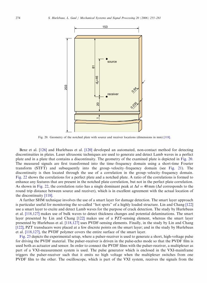
Fig. 20. Geometry of the notched plate with source and receiver locations (dimensions in mm) [118].
S. Hurlebaus, L. Gaul / Mechanical Systems and Signal Processing 20 (2006) 255–281274
Benz et al. [126] and Hurlebaus et al. [120] developed an automated, non-contact method for detectingdiscontinuities in plates. Laser ultrasonic techniques are used to generate and detect Lamb waves in a perfectplate and in a plate that contains a discontinuity. The geometry of the examined plate is depicted in Fig. 20.The measured signals are first transformed into the time–frequency domain using a short-time Fouriertransform (STFT) and subsequently into the group–velocity–frequency domain (see Fig. 21). Thediscontinuity is then located through the use of a correlation in the group–velocity–frequency domain.Fig. 22 shows the correlations for a perfect plate and a notched plate. A ratio of the correlations is formed toenhance any features that are present in the notched plate correlation, but not in the perfect plate correlation.As shown in Fig. 22, the correlation ratio has a single dominant peak at Dd ¼ 40mm (Dd corresponds to theround trip distance between source and receiver), which is in excellent agreement with the actual location ofthe discontinuity [118].
A further SHM technique involves the use of a smart layer for damage detection. The smart layer approachis particular useful for monitoring the so-called ‘‘hot spots’’ of a highly loaded structure. Lin and Chang [122]use a smart layer to excite and detect Lamb waves for the purpose of crack detection. The study by Hurlebauset al. [118,127] makes use of bulk waves to detect thickness changes and potential delaminations. The smartlayer presented by Lin and Chang [122] makes use of a PZT-sensing element, whereas the smart layerpresented by Hurlebaus et al. [118,127] uses PVDF-sensing elements. Finally, in the study by Lin and Chang[122], PZT transducers were placed at a few discrete points on the smart layer; and in the study by Hurlebauset al. [118,127], the PVDF polymer covers the entire surface of the smart layer.
Fig. 23 depicts the experimental setup, where a pulser-receiver is used to generate a short, high-voltage pulsefor driving the PVDF material. The pulser-receiver is driven in the pulse-echo mode so that the PVDF film isused both as actuator and sensor. In order to connect the PVDF films with the pulser-receiver, a multiplexer aspart of a VXI-measurement system is used. The pulse generator which is enclosed in the VXI-mainframetriggers the pulser-receiver such that it emits no high voltage when the multiplexer switches from onePVDF film to the other. The oscilloscope, which is part of the VXI system, receives the signals from the

ARTICLE IN PRESS
00 1 2 3 4 5 6 7 8 9 10
1000
2000
3000
4000
5000
6000
frequency [MHz]
grou
p ve
loci
ty [m
/s]
−
Fig. 21. Group–velocity–frequency representation for the notched plate [118].
0 20 40 60 80 100 1200
0.2
0.4
0.6
0.8
1.0
1.0
1.5
2.0
2.5
∆d [mm]
correlation notched plate
correlation perfect plate
ratio notched/ perfect plate
corr
elat
ion
ratio
not
ched
/per
fect
pla
te
Fig. 22. Correlation curves for the perfect plate, notched plate, and a division of both curves [118].
S. Hurlebaus, L. Gaul / Mechanical Systems and Signal Processing 20 (2006) 255–281 275
pulser-receiver, namely, the sensor signal and the synchron signal. The VXI-system is connected to a PC via ageneral purpose interface bus (GPIB). The PC is used for controlling the VXI-system, for storing the data, andfor further signal processing.
The smart layer developed by Hurlebaus et al. contains an embedded network of distributed piezoelectricpolymers. The smart layer was used to identify an ‘‘artificial’’ damage in an aluminium plate(150� 150� 15mm3). The artificial defect is created by milling out some bottom sections at the backsideof the aluminium plate. The depth of the milled section is about 2mm. The boundary of the milled section isshown in Fig. 24 by the solid lines. On top of the aluminium plate, a smart layer is attached using couplant

ARTICLE IN PRESS
no defectidentified
identified
identified
smalldefect
defect
realdefect
Fig. 24. Smart Layer (left) and real and identified defect in the aluminium plate (right) [118,127].
PC
pulser-receiver
VXI system command moduldigitizerpulsegeneratoroscilloscopemultiplexer
screen
GPIB
objectsmart layer
Fig. 23. Experimental setup [118,127].
S. Hurlebaus, L. Gaul / Mechanical Systems and Signal Processing 20 (2006) 255–281276
material. The smart layer is shown in Fig. 24. The electrical connections were obtained using printed circuittechniques. The dark square regions mark a 10� 10 array of PVDF transducers. The side length of eachPVDF element is 10mm, and the distance between sensors is 2mm. The transducers are used both as sendersand receivers. Fig. 24 shows a C-scan of the aluminium plate. The identified defect is much larger than theactual defect. However, this is a consequence of the size and quantity of PVDF transducers which are used. Ifone would use a large array of smaller PVDF transducers, the resolution of the identified defect would be finerand smoother.
9.3. Self-healing– self-repairing
Peairs et al. [128] presented a method for the self-healing of bolted joints. The loosening of a bolted jointconnection is a common structural failure mode. They reported a real-time condition monitoring and activecontrol methodology for bolted joints in civil structures and components. They used an impedance-basedhealth-monitoring technique which utilises the electromechanical coupling property of piezoelectric materialsto identify and detect bolt connection damage. When damage occurs, temporary adjustments of the bolttension can be achieved actively and remotely using shape memory alloy actuators. Specifically, when a boltconnection becomes loose, the bolted members can move relative to each other. The subsequent frictionalheating causes a Nitinol washer to expand axially, thereby leading to a tighter, self-healed bolt connection.
Pang and Bond [129–131] developed a novel composite system which employs a biomimetic approach toperform a self-repairing function. Such a system can perform two functions: the visual enhancement of impactdamage by the bleeding action of a highly conspicuous medium such as fluorescent dye; and, the restoration ofmechanical properties by a healing agent, which is stored within hollow fibres, and which infiltrates andpatches the damaged area upon activation. Impact indentation followed by four-point bend flexural testing

ARTICLE IN PRESSS. Hurlebaus, L. Gaul / Mechanical Systems and Signal Processing 20 (2006) 255–281 277
was conducted to evaluate the strength restoration after self-repair. The results of mechanical testing haveshown that a significant fraction of strength is restored by the self-repairing effect.
10. Conclusions
This paper addresses several fields of application of smart structure dynamics technologies. After discussinga variety of multifunctional materials, some examples for the application of these technologies were given.First, semi-passive concepts used to enhance the damping behaviour of structures were summarised. Thenenergy-harvesting technologies are discussed, and their combination with the shunted piezoelectric concept ishighlighted. Semi-active concepts are also considered, particularly in the context of control of large lightweightspace structures. Next, active concepts are discussed. In addition to active vibration control and active noisecontrol, this paper deals also with the field of active vibration isolation and suppression. Finally, theimplementation of smart structure technologies for in-service monitoring is addressed. Three concepts ofSHM are discussed in more detail: passive sensing diagnostics, active sensing diagnostics, and self-healingstructures. Various smart structure technologies have been developed; The growing use of these technologiesin many potential application areas can be expected: automotive engineering (e.g. cars, trucks), aerospaceengineering (e.g. space shuttle, airplanes), and civil engineering structures (e.g. bridges, tunnels). Avoidingfailure of smart structures during structural life is an important prerequisite and a future challenge.
Acknowledgements
This review article is based in part upon responses to a questionaire directed at leading scientists in the fieldof smart structures. The authors gratefully wish to acknowledge the helpful input received from theseconscientious contributors.
References
[1] U. Gabbert, H. Tzou (Eds.), Smart Structures and Structronic Systems, Kluwer Academic Publisher, Dordrecht, 2001.
[2] S. Hurlebaus, Smart Structures—Fundamentals and Applications, Lecture Notes, Texas A&M University, Zachry Department of
Civil Engineering, 2005.
[3] H. Tzou, H.-J. Lee, S. Arnold, Smart materials, precision sensors/actuators, smart structures and structronic systems, Mechanics of
Advanced Materials and Structures 11 (2004) 367–393.
[4] C. Fuller, S. Elliot, P. Nelson, Active Control of Vibration, Academic Press, London, 1996.
[5] E. Crawley, J. de Luis, Use of piezoelectric actuators as elements of intelligent structures, AIAA Journal 25 (10) (1987) 1373–1385.
[6] V. Piefort, Finite element modelling of piezoelectric active structures, Dissertation, Department of Mechanical Engineering and
Robotics, Universite Libre de Bruxelles, Bruxelles, 2001.
[7] J. Kim, V. Varadan, V. Varadan, X. Bao, Finite element modeling of a smart cantilever plate and comparison with experiments,
Smart Materials and Structures 5 (1996) 165–170.
[8] R. Lammering, S. Mesecke-Rischmann, Multi-field variational formulations and related finite elements for piezoelectric shells,
Smart Materials and Structures 12 (6) (2004) 904–913.
[9] P. Hagedorn, J. Wallaschek, Travelling wave ultrasonic motors, part I: working principle and mathematical modelling of the stator,
Journal of Sound and Vibration 155 (1992) 31–46.
[10] P. Hagedorn, J. Wallaschek, W. Konrad, Travelling wave ultrasonic motors part, II: a numerical method for the flexural vibrations
of the stator, Journal of Sound and Vibration 168 (1993) 115–122.
[11] U. von Wagner, P. Hagedorn, Nonlinearities of piezoceramics subjected to weak electric fields: experiments and modeling, in:
Proceedings of Third International Workshop on Structural Health Monitoring, 2001, pp. 1183–1191.
[12] H. Janocha (Ed.), Adaptronics and Smart Structures, Springer, Berlin, 1999.
[13] R. Lammering, I. Schmidt, Experimental investigations on the damping capacity of NiTi components, Smart Materials and
Structures 10 (2001) 853–859.
[14] C. Rogers (Ed.), Dynamic control concepts using shape memory alloy reinforced plates, in: Smart Materials, Structures, and
Mathematical Issues, Technomic Publishing Company, Cambridge, 1989.
[15] A. Zak, M. Cartmell, W. Ostachowicz, M. Wiercigroch, One-dimensional shape memory alloy models for use with reinforced
composite structures, Smart Materials and Structures 12 (4) (2003) 338–346.
[16] T. Turner, A new thermoelastic model for analysis of shape memory alloy hybrid composites, Journal of Intelligent Material
Systems and Structures 11, 382–394.

ARTICLE IN PRESSS. Hurlebaus, L. Gaul / Mechanical Systems and Signal Processing 20 (2006) 255–281278
[17] B. Davis, T. Turner, S. Seelecke, Active measurement and prediction of the thermomechanical response of shape memory alloy
hybrid composite beams, in: R. Smith (Ed.), Proceedings of SPIE—Smart Structures and Materials 2005: Modeling, Signal
Processing, and Control, 2005, p. 5757
[18] R. DesRoches, J. McCormick, M. Delemont, Cyclical properties of superelastic shape memory alloys, ASCE Journal of Structural
Engineering 130 (1) (2004) 38–46.
[19] H. Janocha (Ed.), Actuators, Springer, Berlin, 2004.
[20] K. Newbury, Characterization, modeling, and control of ionic polymer transducers, Dissertation, Virginia Polytechnic Institute and
State University, Blacksburg, 2002.
[21] K. Newbury, D. Leo, Linear electromechanical model of ionic polymer transducers, part I: model development, Journal of
Intelligent Material Systems and Structures 14 (6) (2003) 333–342.
[22] K. Newbury, D. Leo, Linear electromechanical model of ionic polymer transducers, part II: experimental validation, Journal of
Intelligent Material Systems and Structures 14 (6) (2003) 343–358.
[23] N. Hagood, A. von Flotow, Damping of structural vibrations with piezoelectric materials and passive electrical networks, Journal of
Sound and Vibration 146 (2) (1991) 243–268.
[24] R. Forward, Electronic damping of vibrations in optical structures, Journal of Applied Optics 18 (1979) 690–697.
[25] R. Edwards, R. Miyakawa, Large structure damping task report, Technical Report 132.22/1408, Huges Aircraft Co., 1980.
[26] C. Davis, G. Lesieutre, A modal strain energy approach to the prediction of resistively shunted piezoceramic damping, Journal of
Sound and Vibration 184 (1) (1995) 129–139.
[27] O. Fein, L. Gaul, Reduction of structural vibrations using piezoelectric materials and a passive electrical network, in: 13th
International Conference on Adaptive Structures and Technologies, 2004, pp. 598–606.
[28] O. Fein, L. Gaul, On the application of shunted piezoelectric material to enhance structural damping of a plate, Journal of
Intelligent Material Systems and Structures 15 (2004) 737–743.
[29] O. Fein, L. Gaul, An adaptive shunted piezo approach to reduce structural vibrations, in: Proceedings Smart Structures, vol. 5386,
SPIE, 2004, pp. 393–404.
[30] K. Wang, Y. Lai, W. Yu, Structural vibration control via piezoelectric materials with real-time semi-active electrical networks,
in: E. Garcia, H. Cudney, A. Dasgupta (Eds.), Adaptive Structures and Composite Materials, vol. AD-45, 1994, pp. 219–226.
[31] M. Umeda, K. Nakamura, S. Ueha, Analysis of transformation of mechanical impact energy to electrical energy using a
piezoelectric wafer, Japanese Journal of Applied Physics 35 (5B) (1996) 3267–3273.
[32] T. Starner, Human powered wearable computing, IBM Systems Journal 35 (1996) 618.
[33] J. Kymissis, C. Kendall, J. Paradiso, N. Gershenfeld, Parasitic power harvesting in shoes, in: Second IEEE International Conference
on Wearable Computing, 1998, pp. 132–139.
[34] M. Kimura, Piezoelectric generation device, US Patent and Trademark Office US Patent Nr. 5,801,475, 1998.
[35] M. Goldfarb, L.D. Jones, On the efficieny of electric power generation with piezoelectric ceramic, Journal of Dynamic Systems,
Measurement, and Control 121 (1999) 566–571.
[36] W. Clark, M.J. Ramsay, Smart material transducers as power sources for mems devices, in: International Symposium on Smart
Structures and Microsystems, Hong Kong, 2000
[37] N. Elvin, A. Elvin, M. Spector, A self-powered mechanical strain energy sensor, Smart Materials and Structures 10 (2000) 293–299.
[38] A. Kasyap, J. Lim, D. Johnson, S. Horowitz, T. Nishida, K. Ngo, M. Sheplak, L. Cattafesta, Energy reclamation from a vibrating
piezoceramic composite beam, in: Proceedings of the Nineth International Congress on Sound and Vibration, Orlando, FL, 2002.
[39] J. Gonzalez, F. Moll, A. Rubio, A prospect on the use of piezoelectric effect to supply power to wearable electronic devices, in:
International Center for Material Research, vol. 1, Akita, Japan, 2001, pp. 202–207.
[40] H. Sodano, E. Magliula, G. Park, D. Inman, Electric power generation using piezoelectric devices, in: 13th International Conference
on Adaptive Structures and Technologies, 2004, pp. 153–161.
[41] G.A. Lesieutre, H. Hofmann, G. Ottmann, Structural damping due to piezoelectric energy harvesting, in: 13th International
Conference on Adaptive Structures and Technologies, 2004, pp. 368–377.
[42] D. Karnopp, M. Crosby, R. Harwood, Vibration control using semi-active force generators, Journal of Engineering for Industry 96
(2) (1974) 619–626.
[43] D. Karnopp, Force generation in semi-active suspensions using modulated dissipative elements, Vehicle System Dynamics 16 (1987)
333–343.
[44] D. Hrovat, D. Margilis, M. Hubbart, An approach toward the optimal semi-active suspension, Journal of Dynamic Systems,
Measurement and Control 110 (1988) 288–296.
[45] D. Karnopp, Design principles for vibration control systems using semi-active dampers, Journal of Dynamic Systems, Measurement,
and Control 112 (1990) 448–455.
[46] D. Karnopp, Active and semi-active vibration isolation, Transactions of the ASME 117 (1995) 177–185.
[47] D. Karnopp, R. Allen, Semiactive control of multimode vibratory systems using the ilsm concept, Journal of Engineering for
Industry 98 (3) (1976) 914–918.
[48] P. Davis, D. Cunningham, A. Bicos, M. Enright, Adaptable passive viscous damper (an adatable D-struttm), in: Proceedings of SPIE
International Society of Optical Engineering, vol. 2193, Orlando, FL, 1994, pp. 47–58.
[49] H. McClamroch, H. Gavin, D. Oritz, R. Hanson, Electrorheological dampers and semi-active structural control, in: Proceedings of
the 33rd Conference on Decision and Control, Lake Buena Vista, FL, 1994, pp. 97–102.
[50] K. Wang, Y. Kim, D. Shea, Structural vibration control via electrorheological-fluid-based actuators with adaptive viscous and
frictional damping, Journal of Sound and Vibration 177 (2) (1994) 227–237.

ARTICLE IN PRESSS. Hurlebaus, L. Gaul / Mechanical Systems and Signal Processing 20 (2006) 255–281 279
[51] S. Cao, S. Semercigil, A semi-active controller for excessive transient vibrations of light structures, Journal of Sound and Vibration
178 (2) (1994) 145–161.
[52] J.R. Anderson, A. Ferri, Behavior of a single-degree-of-freedom system with a generalized friction law, Journal of Sound and
Vibrations 140 (2) (1990) 287–304.
[53] Y. Kim, K. Wang, On the sliding mode control of structural vibrations via variable damping, Mechanical Systems and Signal
Processing 7 (3) (1993) 335–347.
[54] O. Vaculin, M. Tapavicza, L. Bose, F. Altmann, Modelling and simulation of an experimental vehicle with magnetorheological
dampers, in: Proceedings of Euromech Colloquium of Semi-active Vibration Suppression, Euromech, 2004, pp. 1–14.
[55] Z. Sika, M. Valasek, Nonlinear versus linear control of semiactive vibration isolation, in: Proceedings of Euromech Colloquium of
Semi-active Vibration Suppression, Euromech, 2004, pp. 1–12.
[56] A. Preumont, Semi-active sky-hook, does it work?, in: Proceedings of Euromech Colloquium of Semi-active Vibration Suppression,
Euromech, 2004, pp. 1–10.
[57] P. De Man, P. Lemerle, P. Mistrot, J.-P. Verschueren, A. Preumont, An investigation of a semi-active suspension for a fork lift
truck, in: Proceedings of Euromech Colloquium of Semi-active Vibration Suppression, Euromech, 2004, pp. 1–15.
[58] L. Gaul, S. Bohlen, Identification of nonlinear structural joint models and implementation in discretized structure models, in: The
Role of Damping in Vibration and Noise Control, vol. DE 5, ASME, 1987, pp. 213–219.
[59] J. Onoda, T. Endo, H. Tamaoki, N. Watanabe, Vibration suppression by variable stiffness members, AIAA Journal 29 (6) (1991)
977–983.
[60] J. Onoda, K. Minesugi, Semiactive vibration suppression of truss structures by Coulomb friction, Journal of Spacecraft and Rockets
31 (1) (1994) 67–74.
[61] J. Holnicki-Szulc, P. Pawlowski, M. Wiklo, High performance impact absorbing materials—the concept design tools and
applications, Smart Materials and Structures 12 (2003) 461–467.
[62] J. Holnicki-Szulc, L. Knap, Adaptive crashworthiness concept, International Journal of Impact Engineering 30 (6) (2004)
639–663.
[63] L. Gaul, Active control of joints in mechanical members and structures, German Patent and Trademark Office Patent Nr. DE 197 02
518.8.
[64] L. Gaul, J. Lenz, D. Sachau, Active damping of space structures by contact pressure control in joints, Mechanics of Structures and
Machines 26(1).
[65] C. Canudas de Wit, H. Olsson, K. Astrom, P. Lischinsky, A new model for control of systems with friction, IEEE Transactions on
Automatic Control 40 (3) (1995) 419–425.
[66] L. Gaul, R. Nitsche, Role of friction in mechanical joints, Applied Mechanics Reviews 54 (2) (2001) 93–105.
[67] B. Armstrong-Helouvry, P. Dupont, C. Canudas de Wit, A survey of models, analysis tools and compensation methods for the
control of machines with friction, Automatica 30 (7) (1994) 1083–1138.
[68] R. Nitsche, Semi-active control of friction damped systems, Ph.D. Thesis, Institut A fur Mechanik, Universitat Stuttgart, Stuttgart,
2001.
[69] L. Gaul, R. Nitsche, Friction control for vibration suppression, Mechanical Systems and Signal Processing 14 (2) (2000) 139–150.
[70] L. Gaul, R. Nitsche, Lyapunov design of damping controllers, Archive of Applied Mechanics 72 (2003) 865–874.
[71] J. Lane, A. Ferri, B. Heck, Vibration control using semi-active friction damping, in: R. Ibrahim, A. Soom (Eds.), ASME Publication
DE-vol. 49, 1992, pp. 165–171.
[72] H. Albrecht, Adaptive Verbindungselemente im Leichtbau, Ph.D. Thesis, Institut A fur Mechanik, Universitat Stuttgart, Stuttgart,
2005.
[73] L. Gaul, H. Albrecht, S. Hurlebaus, Semi-active friction damping of flexible lightweight structures, in: Proceedings of Euromech
Colloquium of Semi-active Vibration Suppression, Euromech, 2004, pp. 1–10.
[74] L. Gaul, H. Albrecht, J. Wirnitzer, Semi-active friction damping of large space truss structures, Journal of Shock and Vibration 11
(3–4) (2004) 173–186.
[75] J. Wirnitzer, Schwingungsreduktion flexibler Raumfahrtstrukturen durch semi-aktive Reibverbindungen, Ph.D. Thesis, Institut A
fur Mechanik, Universitat Stuttgart, Stuttgart, 2004.
[76] C. Swigert, R. Forward, Electronic damping of orthogonal bending modes in a cylindrical mast-theory, Journal of Spacecraft and
Rockets 18 (1) (1981) 5–10.
[77] T. Bailey, J. Hubbard, Distributed piezoelectric-polymer active vibration control of a cantilever beam, Journal of Guidance and
Control 8 (5) (1985) 605–611.
[78] J. Aubrun, Theory of the control of structures by low-authority controllers, Journal of Guidance, Control, and Dynamics 3 (5)
(1980) 444–451.
[79] J. Fanson, T. Caughek, Positive position feedback control for large space structures, AIAA Journal 28 (4) (1990) 717–724.
[80] J. Dosch, D. Inman, E. Garcia, A self-sensing piezolectric actuator for collocated control, Journal of Intelligent Material Systems
and Structures 3 (1992) 166–185.
[81] A. Preumont, A. Francois, P. De Man, V. Piefort, Spatial filters in structural control, Journal of Sound and Vibration 265 (2003)
61–79.
[82] U. Stobener, L. Gaul, Modal vibration control for PVDF coated plates, Journal of Intelligent Material Systems and Structures 11
(4) (2000) 283–293.
[83] U. Stobener, L. Gaul, Active vibration control of a car body based on experimentally evaluated modal parameters, Mechanical
Systems and Signal Processing 15 (1) (2001) 173–188.

ARTICLE IN PRESSS. Hurlebaus, L. Gaul / Mechanical Systems and Signal Processing 20 (2006) 255–281280
[84] U. Stobener, Untersuchungen zur schwingungs- und schallabstrahlungsregelung flachenhafter strukturen, Dissertation, Institut A
fur Mechanik, Universitat Stuttgart, Stuttgart, 2002.
[85] P. Lueg, Process of silencing sound oscillations, US Patent and Trademark Office Patent No. 2,043,416, 1936.
[86] H. Olson, E. May, Electronic sound absorber, Journal of the Acoustical Society of America 25 (6) (1953) 1130–1136.
[87] W.D. Conover, Fighting noise with noise, Noise Control 2 (2) (1956) 78–82.
[88] H. Lester, C. Fuller, Active control of propeller-induced noise fields inside a flexible cylinder, AIAA Journal 28 (8) (1990)
1374–1380.
[89] S. Elliott, P. Nelson, I. Stothers, C. Boucher, In flight experiments on the active control of propeller-induced cabin noise, Journal of
Sound and Vibration 140 (2) (1990) 219–238.
[90] C. Gerner, D. Sachau, H. Breitbach, Active noise control in a semi-enclosure within an aircraft cabin, in: Proceedings of the Tenth
International Congress on Sound and Vibration, 2003, pp. 3721–3726.
[91] T. Sutton, S. Elliott, A. McDonald, T. Saunders, Active control of road noise inside vehicles, Noise Control Engineering Journal 42
(4) (1994) 137–147.
[92] C. Fuller, Active control of sound transmission/radiation from elastic plates by vibration inputs. i. analysis, Journal of Sound and
Vibration 136 (1) (1990) 1–15.
[93] C. Fuller, C. Hansen, S. Snyder, Active control of sound radiation from a vibrating rectangular panel by sound sources and
vibration inputs an experimental comparison, Journal of Sound and Vibration 145 (2) (1991) 195–215.
[94] S. Snyder, C. Hansen, The effect of transfer function estimation errors on the filtered-x lms algorithm, IEEE Transactions on Signal
Processing 42 (4) (1994) 950–953.
[95] N. Tanaka, Y. Kikushima, M. Kuroda, S. Snyder, Active control of acoustic power radiated from a vibrating planar structure using
smart sensors (acoustic power suppression using adaptive feedforward control), JSME International Journal 39 (1) (1996) 49–57.
[96] J. Carneal, C. Fuller, An analytical and experimental investigation of active structural acoustic control of noise transmission
through double panel systems, Journal of Sound and Vibration 272 (3) (2004) 749–771.
[97] R. Fraanje, M. Verhaegen, N. Doelman, Increasing the robustness of a preconditioned filtered-x lms algorithm, IEEE Signal
Processing Letters 11 (2) (2004) 285–288.
[98] F. Deuble, C. Hofmann, B. Kroplin, K. H. Well, Active structural acoustic control: Numerical modelling, robust controller design
and experimental validation, in: Proceedings of SPIE—The International Society for Optical Engineering, 4693, 2002, pp. 45–56.
[99] F. Deuble, Modellbasiertere Entwurfsmethoden fur die Struktur-Akustik-Regelung, Dissertation, Institut fur Statik und Dynamik
der Luft- und Raumfahrtkonstruktion, Universitat Stuttgart, Stuttgart, 2003.
[100] U. Stobener, L. Gaul, Active vibration and noise control by hybrid active acoustic panels, Zeitschrift fur Angewandte Mathematik
und Mechanik 81 (1) (2001) 45–48.
[101] C. Hsu, C. Lin, L. Gaul, Vibration and sound radiation controls of beams using layered modal sensors and actuators, Smart
Materials and Structures 7 (4) (1998) 446–455.
[102] P. Hagedorn, U. von Wagner, Smart pads: a new tool for the suppression of brake squeal?, in: Proceedings of XXIV m-Kolloquium,
vol. 575, VDI, 2004, pp. 153–172.
[103] U. Stobener, L. Gaul, Piezoelectric stack actuator: Fe-modeling and application for vibration isolation, in: A. Preumont (Ed.),
Proceedings of the NATO Advanced Study Institute on Responsive Systems for Active Vibration Control, Kluwer Academic
Publishers, Dordrecht, 2001, pp. 253–265.
[104] X. Huang, S.J. Elliott, M.J. Brennan, Active isolation of a flexible structure from base vibration, Journal of Sound and Vibration
263 (2003) 357–376.
[105] A. Preumont, Vibration Control of Active Structures, Kluwer Academic Publishers, Dordrecht, 1997.
[106] A. Preumont, A. Francois, F. Bossens, A. Abu-Hanieh, Force feedback versus acceleration feedback in active vibration isolation,
Journal of Sound and Vibration 257 (4) (2002) 605–613.
[107] S. Riebe, H. Ulbrich, Modelling and online computation of the dynamics of a parallel kinematic with six degrees-of-freedom,
Archive of Applied Mechanics 72 (2003) 817–829.
[108] T. Muller, S. Hurlebaus, U. Stobener, L. Gaul, Modelling and control of an active vibration isolation system, in: Proceedings of the
International Modal Analysis Conference IMAC, Orlando, FL, 2005.
[109] B. Beadle, S. Hurlebaus, U. Stobener, L. Gaul, Modelling and parameter identification of an anti vibration system, in: Proceedings
of the SPIE, San Diego, CA, 2005.
[110] F. Kerber, Regelung eines aktiven Schwingungsisolationssystems, Studienarbeit, Institute A of Mechanics, University of Stuttgart,
2005.
[111] S. Doebling, C. Farrar, M. Prime, D. Shevitz, Damage identification and health monitoring of structural and mechanical systems
from changes in their vibration characteristics: a literature review, Report la-13070-ms, Los Alamos National Laboratory,
Engineering Sciences and Applications Division, Engineering Analysis Group, May 1996.
[112] F.-K. Chang (Ed.), Structural Health Monitoring 2000, Technomic Publ. Co., Lancaster, 1999.
[113] K. Choi, F.-K. Chang, Identification of impact force and location using distributed sensors, Journal of AIAA 34 (1) (1996) 136–142.
[114] M. Tracy, F.-K. Chang, Identifying impact load in composite plates based on distributed piezoelectric sensor measurements, in:
Proceedings of the SPIE Smart Structures and Materials Conference, San Diego, 1996.
[115] K. Kishimoto, H. Inoue, M. Hamada, T. Shibuya, Time frequency analysis of dispersive waves by means of wavelet transform,
Journal of Applied Mechanics 62 (4) (1995) 841–846.
[116] H. Inoue, K. Kishimoto, T. Shibuya, Experimental wavelet analysis of flexural waves in beams, Experimental Mechanics 36 (3)
(1996) 212–217.

ARTICLE IN PRESSS. Hurlebaus, L. Gaul / Mechanical Systems and Signal Processing 20 (2006) 255–281 281
[117] L. Gaul, S. Hurlebaus, Identification of the impact location on a plate using wavelets, Mechanical Systems and Signal Processing 12
(6) (1998) 783–795.
[118] S. Hurlebaus, A contribution to structural health monitoring using elastic waves, Dissertation, Institut A fur Mechanik, Universitat
Stuttgart, Stuttgart, 2002.
[119] L. Gaul, S. Hurlebaus, Determination of the impact force on a plate by piezoelectric film sensors, Archive of Applied Mechanics 69
(9/10) (1999) 691–701.
[120] L. Gaul, S. Hurlebaus, L. Jacobs, Localization of a ‘synthetic’ acoustic emission source on the surface of a fatigue specimen,
Research in Nondestructive Testing 13 (2) (2001) 105–117.
[121] C. Boller, C. Biemans, Structural health monitoring in aircraft—state-of-the-art perspectives and benefits, in: F.-K. Chang (Ed.),
Structural Health Monitoring: Current Status and Perspectives, Technomics Publishing company, Stanford, CA, 1997, pp. 541–552.
[122] M. Lin, F.-K. Chang, Development of SMART layer for built-in diagnostics for composite structures, in: The 13th Annual ASC
Technical Conferences on Composite Material, American Society of Composite, Baltimore, MD, 1998, pp. 1–8.
[123] P. Wilcox, R. Dalton, M. Lowe, P. Cawley, Mode selection and transduction for structural health monitoring using Lamb waves, in:
F.-K. Chang (Ed.), Structural Health Monitoring 2000, Technomic Publishing Company Inc., Lancaster, 1999, pp. 703–712.
[124] M. Lemistre, D. Balageas, Structural health monitoring system based on diffracted Lamb wave analysis by multiresolution
processing, Smart Materials and Structures 10 (3) (2001) 504–511.
[125] U. Berger, U. Muller, H. Baier, Strukturuberwachung mit integrierter faseroptischer Sensorik und Lamb-Wellentechnik, in:
Deutscher Luft- und Raumfahrtkongress 2004, Dresden, 2004
[126] R. Benz, M. Niethammer, S. Hurlebaus, L. Jacobs, Localization of notches with Lamb waves, Journal of Acoustical Society of
America 114 (2) (2003) 677–685.
[127] S. Hurlebaus, L. Gaul, Smart layer for damage diagnostics, Journal of Intelligent Material Systems and Structures 15 (2004)
729–736.
[128] D. Peairs, G. Park, D. Inman, Practical issues of activating self-repairing bolted joints, Smart Materials and Structures 13 (6) (2004)
1414–1423.
[129] J. Pang, I. Bond, Bleeding composites—damage detection and self-repair using a biometric approach, Composites A 36 (2004)
183–188.
[130] J. Pang, I. Bond, Development and evaluation of self-repairing concepts for composite materials, in: Second International
Conference on Composite Testing and Model Identification, CompTest2004, University of Bristol, Sept. 21–23, 2004.
[131] J. Pang, I. Bond, Bleeding composites—enhancing damage detection and effecting self-repair, in: Smart Coatings III, Berlin, June
7–8, 2004.