Review of magnetohydrodynamic pump applications · Nanofluid MHD pumping is a promising technology...
12
REVIEW Review of magnetohydrodynamic pump applications O.M. Al-Habahbeh * , M. Al-Saqqa, M. Safi, T. Abo Khater Department of Mechatronics Engineering, Faculty of Engineering and Technology, The University of Jordan, Jordan Received 1 May 2015; revised 23 February 2016; accepted 3 March 2016 Available online 24 March 2016 KEYWORDS Magnetohydrodynamic (MHD) pump; Seawater pump; Molten metal pump; Molten salt pump; Nano-fluid Pump; Micro-pump Abstract Magneto-hydrodynamic (MHD) principle is an important interdisciplinary field. One of the most important applications of this effect is pumping of materials that are hard to pump using conventional pumps. In this work, the progress achieved in this field is surveyed and organized according to the type of application. The literature of the past 27 years is searched for the major developments of MHD applications. MHD seawater thrusters are promising for a variety of appli- cations requiring high flow rates and velocity. MHD molten metal pump is important replacement to conventional pumps because their moving parts cannot stand the molten metal temperature. MHD molten salt pump is used for nuclear reactor coolants due to its no-moving-parts feature. Nanofluid MHD pumping is a promising technology especially for bioapplications. Advantages of MHD include silence due to no-moving-parts propulsion. Much progress has been made, but with MHD pump still not suitable for wider applications, this remains a fertile area for future research. Ó 2016 Faculty of Engineering, Alexandria University. Production and hosting by Elsevier B.V. This is an open access article under the CC BY-NC-ND license (http://creativecommons.org/licenses/by-nc-nd/4.0/). Contents 1. Introduction ........................................................................... 1348 1.1. Definition......................................................................... 1348 1.2. Theory of operation ................................................................. 1348 1.3. Overview of MHD pump applications .................................................... 1350 2. Seawater pumping ....................................................................... 1350 3. Molten metal pumping.................................................................... 1353 4. Molten salt pumping ..................................................................... 1354 5. Nanofluid pumping ...................................................................... 1355 * Corresponding author. E-mail addresses: [email protected] (O.M. Al-Habahbeh), [email protected] (M. Al-Saqqa), [email protected] (M. Safi), [email protected] (T. Abo Khater). Peer review under responsibility of Faculty of Engineering, Alexandria University. Alexandria Engineering Journal (2016) 55, 1347–1358 HOSTED BY Alexandria University Alexandria Engineering Journal www.elsevier.com/locate/aej www.sciencedirect.com http://dx.doi.org/10.1016/j.aej.2016.03.001 1110-0168 Ó 2016 Faculty of Engineering, Alexandria University. Production and hosting by Elsevier B.V. This is an open access article under the CC BY-NC-ND license (http://creativecommons.org/licenses/by-nc-nd/4.0/).
Transcript of Review of magnetohydrodynamic pump applications · Nanofluid MHD pumping is a promising technology...

Alexandria Engineering Journal (2016) 55, 1347–1358
HO ST E D BY
Alexandria University
Alexandria Engineering Journal
www.elsevier.com/locate/aejwww.sciencedirect.com
REVIEW
Review of magnetohydrodynamic pump
applications
* Corresponding author.
E-mail addresses: [email protected] (O.M. Al-Habahbeh), [email protected] (M. Al-Saqqa), [email protected] (M
[email protected] (T. Abo Khater).
Peer review under responsibility of Faculty of Engineering, Alexandria University.
http://dx.doi.org/10.1016/j.aej.2016.03.0011110-0168 � 2016 Faculty of Engineering, Alexandria University. Production and hosting by Elsevier B.V.This is an open access article under the CC BY-NC-ND license (http://creativecommons.org/licenses/by-nc-nd/4.0/).
O.M. Al-Habahbeh *, M. Al-Saqqa, M. Safi, T. Abo Khater
Department of Mechatronics Engineering, Faculty of Engineering and Technology, The University of Jordan, Jordan
Received 1 May 2015; revised 23 February 2016; accepted 3 March 2016
Available online 24 March 2016
KEYWORDS
Magnetohydrodynamic
(MHD) pump;
Seawater pump;
Molten metal pump;
Molten salt pump;
Nano-fluid Pump;
Micro-pump
Abstract Magneto-hydrodynamic (MHD) principle is an important interdisciplinary field. One of
the most important applications of this effect is pumping of materials that are hard to pump using
conventional pumps. In this work, the progress achieved in this field is surveyed and organized
according to the type of application. The literature of the past 27 years is searched for the major
developments of MHD applications. MHD seawater thrusters are promising for a variety of appli-
cations requiring high flow rates and velocity. MHD molten metal pump is important replacement
to conventional pumps because their moving parts cannot stand the molten metal temperature.
MHD molten salt pump is used for nuclear reactor coolants due to its no-moving-parts feature.
Nanofluid MHD pumping is a promising technology especially for bioapplications. Advantages
of MHD include silence due to no-moving-parts propulsion. Much progress has been made, but
with MHD pump still not suitable for wider applications, this remains a fertile area for future
research.� 2016 Faculty of Engineering, Alexandria University. Production and hosting by Elsevier B.V. This is an
open access article under the CC BY-NC-ND license (http://creativecommons.org/licenses/by-nc-nd/4.0/).
Contents
1. Introduction . . . . . . . . . . . . . . . . . . . . . . . . . . . . . . . . . . . . . . . . . . . . . . . . . . . . . . . . . . . . . . . . . . . . . . . . . . . 1348
1.1. Definition. . . . . . . . . . . . . . . . . . . . . . . . . . . . . . . . . . . . . . . . . . . . . . . . . . . . . . . . . . . . . . . . . . . . . . . . . 13481.2. Theory of operation . . . . . . . . . . . . . . . . . . . . . . . . . . . . . . . . . . . . . . . . . . . . . . . . . . . . . . . . . . . . . . . . . 13481.3. Overview of MHD pump applications . . . . . . . . . . . . . . . . . . . . . . . . . . . . . . . . . . . . . . . . . . . . . . . . . . . . 1350
2. Seawater pumping . . . . . . . . . . . . . . . . . . . . . . . . . . . . . . . . . . . . . . . . . . . . . . . . . . . . . . . . . . . . . . . . . . . . . . . 1350
3. Molten metal pumping. . . . . . . . . . . . . . . . . . . . . . . . . . . . . . . . . . . . . . . . . . . . . . . . . . . . . . . . . . . . . . . . . . . . 13534. Molten salt pumping . . . . . . . . . . . . . . . . . . . . . . . . . . . . . . . . . . . . . . . . . . . . . . . . . . . . . . . . . . . . . . . . . . . . . 13545. Nanofluid pumping . . . . . . . . . . . . . . . . . . . . . . . . . . . . . . . . . . . . . . . . . . . . . . . . . . . . . . . . . . . . . . . . . . . . . . 1355
. Safi),
1348 O.M. Al-Habahbeh et al.
6. Conclusion . . . . . . . . . . . . . . . . . . . . . . . . . . . . . . . . . . . . . . . . . . . . . . . . . . . . . . . . . . . . . . . . . . . . . . . . . . . . 1356
References . . . . . . . . . . . . . . . . . . . . . . . . . . . . . . . . . . . . . . . . . . . . . . . . . . . . . . . . . . . . . . . . . . . . . . . . . . . . 1357
1. Introduction
From space ships to military submarines and power genera-tion; high speed electromagnetic propulsion is widely used
and studied. For example, some propulsion systems requirepumping force without any moving parts. Other systems likespace ships have no air and not enough fuel to thrust. Systems
with very high temperature like molten metal or liquid can bedriven or steered using MHD force. MHD force can providethrusting force for plasma thruster used in space ships. Onthe other hand, conductive metals and molten salts can gener-
ate power using MHD principle. Therapeutic MHD can beused as a micro-pump for blood pumping to maintain sugarlevel in blood. MHD micro-pumps have attracted interest
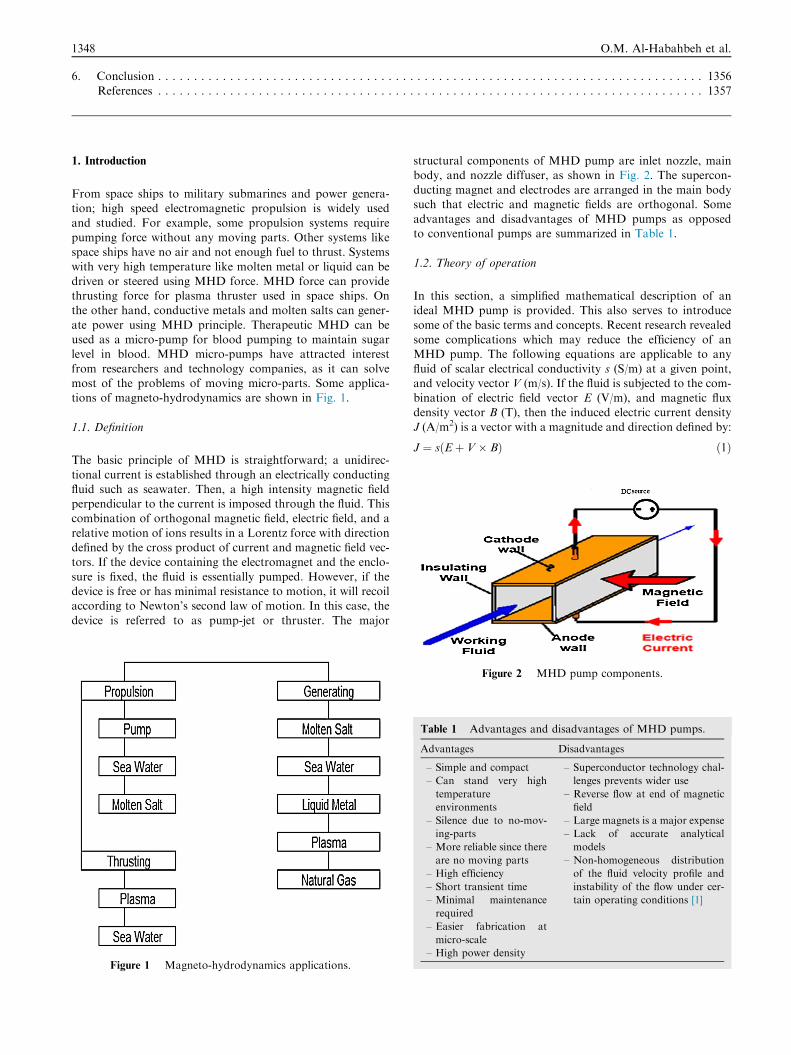
from researchers and technology companies, as it can solvemost of the problems of moving micro-parts. Some applica-tions of magneto-hydrodynamics are shown in Fig. 1.
1.1. Definition
The basic principle of MHD is straightforward; a unidirec-
tional current is established through an electrically conductingfluid such as seawater. Then, a high intensity magnetic fieldperpendicular to the current is imposed through the fluid. Thiscombination of orthogonal magnetic field, electric field, and a
relative motion of ions results in a Lorentz force with directiondefined by the cross product of current and magnetic field vec-tors. If the device containing the electromagnet and the enclo-
sure is fixed, the fluid is essentially pumped. However, if thedevice is free or has minimal resistance to motion, it will recoilaccording to Newton’s second law of motion. In this case, the
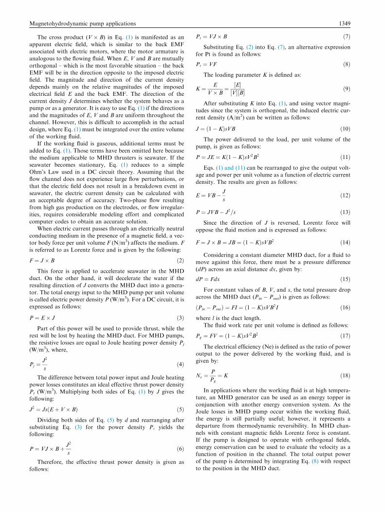
device is referred to as pump-jet or thruster. The major
Figure 1 Magneto-hydrodynamics applications.
structural components of MHD pump are inlet nozzle, mainbody, and nozzle diffuser, as shown in Fig. 2. The supercon-ducting magnet and electrodes are arranged in the main bodysuch that electric and magnetic fields are orthogonal. Some
advantages and disadvantages of MHD pumps as opposedto conventional pumps are summarized in Table 1.
1.2. Theory of operation
In this section, a simplified mathematical description of anideal MHD pump is provided. This also serves to introduce
some of the basic terms and concepts. Recent research revealedsome complications which may reduce the efficiency of anMHD pump. The following equations are applicable to any
fluid of scalar electrical conductivity s (S/m) at a given point,and velocity vector V (m/s). If the fluid is subjected to the com-bination of electric field vector E (V/m), and magnetic fluxdensity vector B (T), then the induced electric current density
J (A/m2) is a vector with a magnitude and direction defined by:
J ¼ sðEþ V� BÞ ð1Þ
Figure 2 MHD pump components.
Table 1 Advantages and disadvantages of MHD pumps.
Advantages Disadvantages
– Simple and compact
– Can stand very high
temperature
environments
– Silence due to no-mov-
ing-parts
– More reliable since there
are no moving parts
– High efficiency
– Short transient time
– Minimal maintenance
required
– Easier fabrication at
micro-scale
– High power density
– Superconductor technology chal-
lenges prevents wider use
– Reverse flow at end of magnetic
field
– Large magnets is a major expense
– Lack of accurate analytical
models
– Non-homogeneous distribution
of the fluid velocity profile and
instability of the flow under cer-
tain operating conditions [1]
Magnetohydrodynamic pump applications 1349
The cross product (V � B) in Eq. (1) is manifested as anapparent electric field, which is similar to the back EMFassociated with electric motors, where the motor armature is
analogous to the flowing fluid. When E, V and B are mutuallyorthogonal – which is the most favorable situation – the backEMF will be in the direction opposite to the imposed electric
field. The magnitude and direction of the current densitydepends mainly on the relative magnitudes of the imposedelectrical field E and the back EMF. The direction of the
current density J determines whether the system behaves as apump or as a generator. It is easy to use Eq. (1) if the directionsand the magnitudes of E, V and B are uniform throughout thechannel. However, this is difficult to accomplish in the actual
design, where Eq. (1) must be integrated over the entire volumeof the working fluid.
If the working fluid is gaseous, additional terms must be
added to Eq. (1). Those terms have been omitted here becausethe medium applicable to MHD thrusters is seawater. If theseawater becomes stationary, Eq. (1) reduces to a simple
Ohm’s Law used in a DC circuit theory. Assuming that theflow channel does not experience large flow perturbations, orthat the electric field does not result in a breakdown event in
seawater, the electric current density can be calculated withan acceptable degree of accuracy. Two-phase flow resultingfrom high gas production on the electrodes, or flow irregular-ities, requires considerable modeling effort and complicated
computer codes to obtain an accurate solution.When electric current passes through an electrically neutral
conducting medium in the presence of a magnetic field, a vec-
tor body force per unit volume F (N/m3) affects the medium. Fis referred to as Lorentz force and is given by the following:
F ¼ J� B ð2ÞThis force is applied to accelerate seawater in the MHD
duct. On the other hand, it will decelerate the water if theresulting direction of J converts the MHD duct into a genera-
tor. The total energy input to the MHD pump per unit volumeis called electric power density P (W/m3). For a DC circuit, it isexpressed as follows:
P ¼ E� J ð3ÞPart of this power will be used to provide thrust, while the
rest will be lost by heating the MHD duct. For MHD pumps,
the resistive losses are equal to Joule heating power density Pj
(W/m3), where,
Pj ¼ J2
sð4Þ
The difference between total power input and Joule heatingpower losses constitutes an ideal effective thrust power densityPt (W/m3). Multiplying both sides of Eq. (1) by J gives the
following:
J2 ¼ JsðEþ V� BÞ ð5ÞDividing both sides of Eq. (5) by d and rearranging after
substituting Eq. (3) for the power density P, yields thefollowing:
P ¼ VJ� Bþ J2
sð6Þ
Therefore, the effective thrust power density is given as
follows:
Pt ¼ VJ� B ð7ÞSubstituting Eq. (2) into Eq. (7), an alternative expression
for Pt is found as follows:
Pt ¼ VF ð8ÞThe loading parameter K is defined as:
K ¼ E
V� B¼ ½E�
½V�½B� ð9Þ
After substituting K into Eq. (1), and using vector magni-tudes since the system is orthogonal, the induced electric cur-rent density (A/m2) can be written as follows:
J ¼ ð1� KÞsVB ð10ÞThe power delivered to the load, per unit volume of the
pump, is given as follows:
P ¼ JE ¼ Kð1� KÞsV2B2 ð11ÞEqs. (1) and (11) can be rearranged to give the output volt-
age and power per unit volume as a function of electric current
density. The results are given as follows:
E ¼ VB� J
sð12Þ
P ¼ JVB� J2=s ð13ÞSince the direction of J is reversed, Lorentz force will
oppose the fluid motion and is expressed as follows:
F ¼ J� B ¼ JB ¼ ð1� KÞsVB2 ð14Þ
Considering a constant diameter MHD duct, for a fluid tomove against this force, there must be a pressure difference
(dP) across an axial distance dx, given by:
dP ¼ Fdx ð15ÞFor constant values of B, V, and s, the total pressure drop
across the MHD duct (Pin � Pout) is given as follows:
Pin � Poutð Þ ¼ FI ¼ ð1� KÞsVB2I ð16Þwhere l is the duct length.
The fluid work rate per unit volume is defined as follows:
Pg ¼ FV ¼ ð1� KÞsV2B2 ð17ÞThe electrical efficiency (Ne) is defined as the ratio of power
output to the power delivered by the working fluid, and isgiven by:
Ne ¼ P
Pg
¼ K ð18Þ
In applications where the working fluid is at high tempera-ture, an MHD generator can be used as an energy topper in
conjunction with another energy conversion system. As theJoule losses in MHD pump occur within the working fluid,the energy is still partially useful; however, it represents a
departure from thermodynamic reversibility. In MHD chan-nels with constant magnetic fields Lorentz force is constant.If the pump is designed to operate with orthogonal fields,
energy conservation can be used to evaluate the velocity as afunction of position in the channel. The total output powerof the pump is determined by integrating Eq. (8) with respectto the position in the MHD duct.

1350 O.M. Al-Habahbeh et al.
An MHD pump consists of the following components:
1- Flow channel
2- Super-conducting magnet3- Electrodes4- Electrical power supply
5- Supporting structure
The magnet makes up around 20% of the total mass. The
remaining mass is basically a structural support to restrain themagnet together. Field strength of 10 T is achievable usingsuper-conducting magnets. Important parameters of coil config-uration for an MHD thruster include weight, efficiency and field
leakage. In real operation, the flow may not be uniform, espe-cially during transient operation, as the magnetic field is gener-ally not uniform across the channel. Since J is coupled with V
and B, the solution of Eq. (7) for the total delivered power isinvolved. Therefore, an approximation for quasi-steady mag-netic flux is computed using the Biot–Savart Law:
B ¼ C1
ZZZV
jmNab
r2
� �dv ð19Þ
whereC1: Magnetic permeability divided by 4
v: Volume of integrationJm: Current density in magnetic coilsNab: Unit vector from point a to point b
r: Distance from a to b
Electric field (E) can be calculated using Eq. (1) and the
steady-state forms of two of Maxwell’s equations are givenas follows:
r� E ¼ 0 ð20Þ
r � J ¼ 0 ð21ÞProvided that the velocity V and the magnetic flux density
B are known, Eq. (20) implies the existence of an electricpotential satisfying the relation:
E ¼ ð�r£Þ ð22ÞSubstituting J from Eq. (1) into Eq. (21), and using Eq.
(22), results in a second-order partial differential equation in£, where magnetic flux can be calculated:
r2£ ¼ r � V� B ð23Þ
1.3. Overview of MHD pump applications
A review and evaluation of recent advances in micro-scalepumping technologies was conducted by Iverson and Garimella[2]. However, the review did not include the macro-scale applica-
tions of MHD pumps. An overview of MHD commercialdevices used for industrial applications such as the world largestMHD pump, which is capable of pumping 3500 m3/h of 300 �CSodium, as well as high temperature pumps and submersiblepumps, was presented by Branover and Unger [3]. However, itwas done 25 years ago. Das and Wang [4] illustrated certain
unique applications of MHD pumps that are relevant topoint-of-care diagnostic device design and fabrication. There-fore, there is a need for an up-to-date survey of the progress
achieved in MHD pumps applications.
Despite the fact that the basic MHD principle has beenknown for many years, only few practical applications wereinvestigated. MHD systems still have considerable challenges
ahead before it could become practical. The problems maybe classified into two categories;
(a) Technology-specific, concerning physical phenomena ofsuperconductors.
(b) Practical techniques to examine the possibility of design-
ing and constructing MHD thruster systems.
This investigation focuses on the later kind of problems.It is considered that MHD pump can be designed with the
freedom of configuration and size, so that they could havehigh propulsive performance, as shifting is not required.Some possible configurations of MHD thruster systems have
been proposed for ship propulsion [5]. However, it has notbeen ascertained which configuration of the system isoptimal.
MHD generator or pump is simple and compact, and has ahigh power density. As such, it is especially attractive for mil-itary applications. Compactness and the absence of rotating
machinery were felt to be important from a viewpoint ofreducing noise, especially important in submarine propulsion.The lack of recent publications implies that military applica-tions have caused current MHD developments to be confiden-
tial in nature.The feasibility of MHD propulsion was first demonstrated
by Way [6], who published a very complete and mathemati-
cally rigorous analysis of an external duct DC propulsion sys-tem. In the sixties, few marine models were constructed, butwith little success. Recent developments in super-conductivity
and superconducting magnets are responsible for intenseresearch in MHD propulsion and generation. The Japaneseresearch group JAFSA has made a major contribution to the
development of MHD thrusters for high speed ships [7].JAFSA constructed a 3 m operable model.
In principle, the relationship between MHD pump and gen-erator is analogous to an electrical motor being driven and
operated like a generator. The focus of this work will be onthe operation of an MHD pump, because it is less complex,and has known practical applications. Recent research
revealed many complications which may significantly reducethe achievable efficiency of an MHD pump. However, pro-jected efficiency is still attractive enough for submarine propul-
sion applications. The major applications of MHD pumps willbe discussed, such as pumping of seawater, molten metal, mol-ten salt, and nanofluid pumping.
2. Seawater pumping
MHD thrusters have long been recognized as potentially
attractive candidates for ship propulsion, because such systemseliminate the conventional rotating drive components. TheMHD thruster is essentially an electromagnetic (EM) pump
operating in seawater. Electrical current is passed directlythrough the seawater and interacts with an applied magneticfield; the interaction of the magnetic field and the electrode
current in the seawater results in a Lorentz force acting onthe water, and the reaction to this force propels the vesselforward. The concept of EM propulsion has been examined

Magnetohydrodynamic pump applications 1351
periodically during the past 35 years as an alternative methodof propulsion for surface ships and submersibles.
Magnetic field effect on (CuO) water nanofluid flow was
investigated by Sheikholeslami et al. [8]. They studied the heattransfer in an enclosure which is heated from below. ApplyingLattice-Boltzmann method to solve the governing equations,
the effective thermal conductivity and viscosity of nanofluidwere calculated by KKL (Koo–Kleinstreuer–Li) correlation.In their model, the effect of Brownian motion on the effective
thermal conductivity was considered. Effect of active parame-ter such as: Hartmann number, heat source length, nanoparti-cle volume fraction and Rayleigh numbers on the flow andheat transfer characteristics have been examined. The results
revealed that the enhancement in heat transfer increases withHartmann number and heat source length, and decreases withRayleigh number. It was also found that the effect of Hart-
mann number and heat source length is more pronounced athigh Rayleigh number.
MHD flow and mixed convective heat transfer of Al2O3–
water nanofluid inside a vertical microtube was investigatedtheoretically by Malvandi and Ganji [9]. A two-phase mixturemodel was used for nanofluid in the hypothesis that Brownian
motion and thermophoretic diffusivities are the only signifi-cant slip mechanisms between solid and liquid phases. Dueto non-adherence of the fluid–solid interface resulting frommicroscopic roughness in microtubes, Navier’s slip boundary
condition was considered at the surfaces. Assuming a fullydeveloped flow and heat transfer, the basic partial differentialequations including continuity, momentum, and energy equa-
tions were reduced to two-point ordinary boundary value dif-ferential equations with endpoint singularities, which weresolved numerically. The results indicated that for smaller
nanoparticles, the nanoparticle volume fraction is more uni-form and there are no abnormal variations in the heat transferrate and pressure drop. In addition, heat transfer rate is
enhanced in the presence of the magnetic field especially forthe smaller nanoparticles. Moreover, as the magnetic fieldstrength (Ha) intensifies, the peak of the velocity profile nearthe walls is increased; however, the peak of the velocity profile
at the core region is decreased.Performance calculations for torpedo-sized and submarine-
sized vehicles operating 30 m beneath sea surface have been
done by Lin et al. [10]. It was found that reasonable submarinevelocity can be achieved with a magnetic field of about 5 T.
A numerical investigation of the hydro-thermal behavior of
a ferrofluid (seawater and 4 vol% Fe3O4) was presented byAminfar et al. [11]. The ferrofluid was in a rectangular verticalduct subjected to different magnetic fields, while two-phasemixture model and control volume technique were used. Con-
sidering the electrical conductivity of the ferrofluid, in additionto the ferrohydrodynamics principles, the magnetohydrody-namic principles have been taken into account. Three cases
for magnetic field have been considered to study mixed convec-tion of the ferrofluid: non-uniform axial field (negative andpositive gradient), uniform transverse field and the third case
when both fields are applied simultaneously. The results indi-cated that negative gradient axial field and uniform transversefield act similarly and enhance both the Nusselt number and
the friction factor, while positive gradient axial field does theopposite. It is also concluded that under the influence of bothfields, increasing the intensity of uniform transverse fieldresults in decreasing the effect of non-uniform axial fields.
An active boundary layer control system for marine vehi-cles is revealed by Meng [12], where the boundary layer controlsystem comprises a plurality of magnets and seawater elec-
trodes placed in circumferential rows around the beam of thehull. The magnets and electrodes are positioned so that a Lor-entz force generated by the interacting magnetic and electric
fields will drive the boundary layer flow in an axial directiontoward the end of the hull. The boundary layer control systemreduces turbulence and may relaminarizes boundary layer
flow, thereby reducing radiated noise.An MHD model that couples a one-dimensional flow
model to a two-dimensional electrical model was made byDoss and Geyer [13]. Their model has been developed to
demonstrate the need for high strength magnetic fields andto investigate the influence of friction and end losses on theperformance of MHD thrusters. Parametric studies have been
performed using the model that includes the variation of theapplied magnetic field (5–20 T), thruster diameter (0.5–2.0 m), wall roughness (0–3 mm), flow velocity (5–20 m/s),
and the load factor (1–10). The results indicated that frictionand end losses can have a deleterious effect on the thruster effi-ciency close to a load factor of one. Furthermore, the param-
eter studies show that the thruster efficiency increases with thestrength of the magnetic field and thruster diameter anddecreases with wall roughness and flow velocity. Furthermore,it was concluded that careful considerations should be given to
the analysis and design of MHD thrusters for load factorsclose to unity.
Conducting fluid in the micro-channel of MHDmicropump
was studied by Jang and Lee [14]. The micropump is driven byLorentz force in the direction perpendicular to both magneticand electric fields. The performance of the micropump is
obtained by measuring the pressure head difference and flowrate as the applied voltage changes from 10 to 60 VDC at0.19 and 0.44 T (T). The pressure head difference is 18 mm
at 38 mA and the flow rate is 63 ll/min at 1.8 mA, while theinside diameter of inlet/outlet tube is 2 mm and the magneticflux density is 0.44 T. It was noted that bubble generation bythe electrolysis of the conducting liquid can be observed.
Bennecib et al. [15] introduced a complete set of basic equa-tions for a new MHD DC pump. The equations presented asimplified MHD flow model based on steady-state, incom-
pressible and laminar flow theory, and were used to investigatethe characteristics of the proposed MHD DC pump. Finitevolume method was used to solve both electromagnetic and
hydrodynamic models. It was concluded that an active partis necessary in the design of the pump. In addition, it was indi-cated that the thrust performance depends on the electrodelength (L2) and channel radius (Rch) and appeared to favor
L2 = 0.08 m, Rch = 0.03 m as optimized dimensions. Thenumerical results of the pump performance characteristicsshowed that the new concept was capable of delivering bi-
directional activation.Three different thrusters were designed, constructed, and
evaluated by Lin et al. [16]. For the first time, videographic
and photographic recordings of flow through MHD thrusterswere obtained. The MHD-induced flow rate, thrust, andmechanical efficiency were measured and calculated for each
thruster at different combinations of electric current and mag-netic field strength. Direct determination of thrust, and subse-quently of efficiency was not possible. Therefore, the hydraulicresistance of each different thruster was correlated with flow

1352 O.M. Al-Habahbeh et al.
rate. That information was used in conjunction with the mea-sured MHD-induced flow rate to calculate the thrust and effi-ciency of each thruster. As the experimental results were found
repeatable, a theoretical model was developed to predict theperformance of each thruster. The results of the model werepresented for one thruster at several magnetic field strengths
and various electric currents. The predictions correspondedwell with the measured and calculated values of MHD-induced flow rate and mechanical efficiency.
The use of MHD to circulate fluids in conduits fabricatedwith low temperature co-fired ceramic tapes was describedby Zhong et al. [17]. Conduits shaped like toroidal and rectan-gular loops were fabricated. Electrodes printed on the ceramic
substrate along the conduits’ walls facilitated transmission ofelectric currents through the test fluids. When the devices weresubjected to a magnetic field, the resulting Lorentz forces pro-
pelled the liquids.A rectangular closed circuit filled with an electrolyte fluid,
known as macro-pump was examined by Aoki et al. [18]. A
permanent magnet generates magnetic field while electrodesgenerate electric field in the flow. The fluid conductor movesinside the circuit under MHD effect. The MHD model has
been derived from the Navier–Stokes equations and coupledwith the Maxwell equations for Newtonian incompressiblefluid. Electric and magnetic components engaged in the testchamber assisted in creating the propulsion of the electrolyte
fluid. The electromagnetic forces that arose were due to thecross product between the vector density of induced currentand the vector density of applied magnetic field, which results
in Lorentz force. Results were presented for 3D numericalMHD simulation for Newtonian fluid as well as experimentaldata. The goal was to relate the magnetic field with the electric
field and the amount of movement produced, as well as to cal-culate the current density and fluid velocity. The flow analysiswas performed with the magnetic field fixed, while the electric
field is changed. Observing the interaction between the fieldstrengths, and density of the electrolyte fluid, an optimal con-figuration for the flow velocity was determined and comparedwith other publications.
An MHD model that coupled one-dimensional flow to two-dimensional electrical model was developed by Doss andGeyer [13]. The model was used to demonstrate the need for
high strength magnetic fields and to investigate the influenceof friction and end losses on the performance of MHD thrus-ters. Parametric studies have been performed on the model
including the variation of the applied magnetic field from 5–20 T, thruster diameter from 0.5–2.0 m, wall roughness from0–3 mm, flow velocity from 5–20 m/s, and the load factor from1–10. The results indicated that friction and end losses can
have a deleterious effect on the thruster efficiency close to aload factor equal to unity. Furthermore, parametric studiesshowed that the thruster efficiency increases with the strength
of the magnetic field and thruster diameter and decreases withwall roughness and flow velocity.
The coupling between electrochemistry and hydrodynamics
was studied by Boissonneau and Thibault [19]. MHD effect onseawater was used for direct propulsion and flow control.Experimental measurements were carried out in a small
seawater tunnel at their laboratory using seawater with a NaClconcentration of 35 g l�1. The first aspect of their study wasthe effect of electrolysis micro-bubbles on the flow, leadingto modification of the turbulent boundary layer or flow on
bubble characteristics. The second aspect was the effect ofthe flow conditions on the electrode working conditions, suchas the effective electroactive species and the electrode potential
evolution. The main conclusions were that the electrolysismicro-bubbles do not affect the flow in the domain considered.However, in contrast, flow conditions do affect bubble size and
distribution. On the other hand, the competition between elec-troactive species (i.e. anodic reactions) is entirely controlled bythe flow. This means, from a practical point of view, that there
is no opportunity to select an anode material that enables theselection of oxygen evolution instead of chlorine in the condi-tions prescribed by seawater MHD applications.
Two-phase seawater MHD flows were recorded at the cen-
ter of a multi-Tesla solenoid magnet by Lin et al. [20]. A closedseawater loop using a synthetic ‘‘sea salt” solution wasinstalled in and around the magnet. The plexi-glass test section
consisted of two parallel electrodes that passed the DC currentthrough the seawater. The test section was placed at the centerof the magnet with the magnetic field being perpendicular to
the current, so that Lorentz force was created in the axialdirection of the test section. As a result of electrolysis, hydro-gen and chlorine/oxygen gases were produced at the cathode
and anode, respectively. In addition to the visualization ofthe complex two-phase MHD flows, performance of the testsection as an MHD pump was studied as well.
The reasons for the renewed interest in the concept of
MHD seawater propulsion were discussed by Doss and Geyer[21]. They presented the main advantages of this concept,together with some of the technical challenges that need to
be overcome in order to achieve reliability and performance.They discussed in simple terms some of the technical issuesand loss mechanisms influencing the thruster performance in
terms of its electrical efficiency. These issues include jet losses,nozzle efficiency, Ohmic losses, frictional losses, three-dimensional effects and electrolysis inside the thruster. The
studies showed that the frictional and end losses can havestrong adverse effects on the thruster performance, and thatthe thruster efficiency increases with the strength of the mag-netic field and thruster diameter, and decreases with the wall
roughness and the flow velocity.In light of advances in high-temperature superconductivity,
the feasibility of MHD ship propulsion using superconducting
magnets was reviewed by Mitchell and Gubser [22]. Thescaling relations for the electrical and hydraulic efficienciesof MHD pump-jets show that overall efficiencies greater
than 50% are feasible at speeds of 40 knots and higher, pro-vided that magnetic fields greater than 5 T can be maintainedover volumes of the order of 100 m3. The development oflarge-scale electrical machinery and magnets using high-
temperature superconductors could make it practical toconstruct submersibles for high-speed and silent operation.Low-speed tankers for movement of bulk cargo would be
efficient with even lower fields.Different superconducting MHD systems were described in
J. Phys. III France [5], with focus on electromagnetic aspect.
Related programs throughout the world were described aswell. It was reported that magnetic levitated trains could bethe new high speed transportation system for the 21st century.
Intensive studies involving MagLev trains using superconduc-tivity have been carried out in Japan since 1970. In 1991 a sixyear program was launched in the United States to evaluatethe performances of MagLev systems for transportation.

Magnetohydrodynamic pump applications 1353
Japan is also up at the top with the tests of Yamato I, a 260 tonMHD propelled ship.
A small high-temperature superconducting magnet has
been produced by Hales et al. [23] as part of an MHD propul-sion unit to power a model boat. The magnet was wound from6 pancake coils of Bi–Sr–Ca–Cu–O HTS tape, and was con-
duction cooled using an onboard ‘‘thermal battery”, contain-ing 3 liters of solid nitrogen. The magnet was racetrackshaped, and aluminum electrodes were placed along the
straights of the magnet to pass an electric current throughthe saltwater, perpendicular to the magnetic field. Power forthe magnet and the electrodes was provided by onboard sealedlead acid batteries, resulting in a fully ’stand-alone’ magnet
system, which is capable of up to 1.25 h of continuous opera-tion on one battery pack. The system was integrated into amodel boat hull, which was successfully launched in 2004. A
top speed of �30 mm/s was reached during the first trial.Early studies showed that MHD thrusters were impractical,
inefficient, and restricted to fields of 2 T. However, a review
performed by Petrick et al. [24] concluded that with the evolu-tion of superconducting magnet technology, later studiesinvestigated the performance of MHD thrusters with much
higher magnetic field strengths. They concluded that at higherfields (greater than 6 T), practical MHD propulsion systemsappear possible. The feasibility of attaining the requisite highermagnetic fields has increased markedly, because of rapid
advances in building high-field superconducting magnets,and the recent evolution of high-temperature superconductors.
A two-Tesla test facility was designed, built, and operated
by Picologlou et al. [25] to investigate the performance ofMHD seawater thrusters. The results of this investigation wereused to validate MHD thruster performance computer models.
The facility test loop, its components, and their design werepresented in detail. Additionally, the test matrix and itsrational were discussed. Finally, representative experimental
results of the test program were presented, and compared topretest computer model predictions. Good agreement betweenpredicted and measured data had served to validate the thrus-ter performance computer models.
The flow characteristics inside MHD plasma generatorsand seawater thrusters were analyzed and compared by Dossand Roy [26]. They used a three-dimensional computer model
that solves the governing partial differential equations for fluidflow and electrical fields. Calculations had been performed fora Faraday plasma generator and for a continuous electrode
seawater thruster. The results of the calculations showed thatthe effects caused by the interaction of the MHD forces withthe fluid flow are strongly manifested in the case of theMHD generator, as compared to the flow development in
the MHD thruster. The existence of velocity overshoots overthe sidewalls confirmed previously published results forMHD generators with strong MHD interaction. For MHD
thrusters, the velocity profile was found to be slightly flatterover the sidewall as compared to that over the electrode wall.As a result, distinct enhancement of the skin friction exists over
the sidewalls of MHD generators in comparison with that ofMHD thrusters.
The working principle of a DC MHD micropump was
described by Homsy et al. [27]. The pump can be operated athigh current densities in micro-fluidic channels without intro-ducing gas bubbles into the pumping channel. The main designfeature for current generation was a micro-machined frit-like
structure that connects the pumping channel to side reservoirs,where platinum electrodes were located. Current densities upto 4000 A m�2 could be applied without noticeable Joule heat-
ing in the system. Pump performance was studied as a functionof current density and magnetic field intensity, as well as bufferionic strength and pH. Bead velocities up to 1 mm sz1 were
observed in buffered solutions using a 0.4 T NdFeB permanentmagnet, at an applied current density of 4000 A m�2. Thepump was intended for transport of electrolyte solutions hav-
ing a relatively high ionic strength in a DC magnetic field envi-ronment. The application of this pump for the study ofbiological samples in a miniaturized total analysis system withintegrated NMR detection was foreseen.
Recent developments of MHD seawater pumping includethe use of Electro-MHD (EMHD) pumping for the recoveryof oil spills on seawater, which was discussed by Zhaoa et al.
[28]. It is based on the different flow states of oil, air and sea-water under the actions of electro-magnetic force, gravity,buoyancy and interphase force. The EMHD thin oil film
recovery method is essentially an air-oil-seawater three-phaseflow under the action of the electromagnetic field and randomwaves. The key problems include:
(1) Mechanism of wave-multiphase flow-electromagneticfield coupling system.
(2) Dynamic response characteristics of the air-oil-seawater
three-phase flow with electromagnetic field and waves.(3) Design principles of EMHD marine thin oil film dis-
posal system under real conditions.
After ten years of experiments on air-oil-seawater flowunder electromagnetic field, a 35 m3/h prototype has been suc-
cessfully tested.
3. Molten metal pumping
Liquid metal MHD power conversion has been recently pro-posed for electrical pumping of various heat sources. This sys-
tem is based on extension of the Faraday’s law of induction toliquid metal. It contains high density liquid metal and a suit-able thermodynamic fluid. A device for transfer of molten
metal was invented by Bykhovsky and Panov [29]. The devicecomprises a centrifugal conduction MHD pump, arrangedwithin a molten metal bath. It is equipped with a metal hous-ing, a cover, a metal rod, as well as a solenoid. These compo-
nents form a closed magnetic circuit, whereby a magnetic fieldis produced within the working chamber. The working cham-ber is hermetically connected with the pipe for discharge of
molten metal.Branover and Unger [3] discussed extensive metallurgical
applications of MHD such as:
– MHD devices employing liquid working medium for pro-cess applications.
– Electromagnetic (EM) modulation of molten metal flow.– EM pump performance of superconducting MHD devices.– Induction EM alkali-metal pumps.– A physical model for EM-driven flow in channel-induction
furnaces.– Grain refinement in Al alloys via EM vibrational method.– Dendrite growth of solidifying metal in DC magnetic field.

1354 O.M. Al-Habahbeh et al.
– MHD for mass and heat transfer in single-crystal melt
growth.– Inverse EM shaping.– Embrittlement of steel by lead.
– An open cycle MHD disk generator.– Acceleration of gas–liquid piston flows for molten-metalMHD pumps.
– MHD flow around a cylinder.
– New MHD drag coefficients.– Liquid–metal MHD two-phase flow.– And finally, Two-phase liquid gas mixers for MHD energy
conversion.
Gailitis et al. [30] used a screw dynamo scheme to model
liquid–metal pumping experiments. The experiments were usedto study MHD dynamo field generation. The model was filledwith liquid sodium. The model was designed for completeutilization of the pump power. The electrodynamics processes
in the model were calculated. The input and output werearranged along the same line, reducing the critical Reynoldsnumber. The flow rates responding to an external disturbance
were found to correspond to the theory. The experiment sug-gested that the model can achieve the critical flow rate andobserve magnetic field generation.
Electric installations on the base of induction machineswere studied by Khristinich et al. [31]. They considered moltenmetal electromagnetic stirring in mixers, furnaces and ladders,
as well as in refining installations and in a liquid phase of con-tinuously casted ingots. Physical simulation of differential andintegral installations was performed; as a result, methods weresuggested for improving electromagnetic stirrers and techno-
logical process intensification within melting-casting units.New inexpensive electromagnetic equipment was discussed
by Hertwich and Foliforov [32]. The equipment was used for
moving molten aluminum, which could open up attractivetechnical and economic perspectives for melting and castingaluminum. Three types of equipment for the transportation
of molten aluminum were offered; electromagnetic side chan-nel pump, tube pump, and electro-magnetic launder.
An experimental study of a liquid metal flow in a rectangu-lar channel under the influence of an inhomogeneous magnetic
field was presented by Andreev et al. [33]. This was a funda-mental problem of liquid metal MHD. The problem is relevantto the technique of electromagnetic braking in the process of
continuous casting of steel, as well as for Lorentz forcevelocimetry. Based on local velocity and electric potential mea-surements, they identified three distinct flow regions; 1. A tur-
bulence suppression region, 2. A vortical region and 3. A walljet region. It was shown that in region (1) the applied inhomo-geneous magnetic field breaks the incoming flow in its central
part and transforms the velocity profile, which was initiallyflat, into an M-shaped form. In the central part of the flow,the intensity of the velocity fluctuations was found to decreasestrongly. In region (2) the magnetic field was the strongest. The
flow was characterized by large-scale vortical structureswhich are time dependent for certain values of the controlparameters. In region (3) downstream of the magnetic system,
two sidewall boundary layers were observed to generate veloc-ity fluctuations with intensity up to 25% of the mean flow.These boundary layers bear close resemblance to wall jets
known from ordinary hydrodynamics. The experimental data
provided a comprehensive database against which numericalsimulations and turbulence models can be tested.
Results of 3D numerical MHD simulation of DC EM
pump were presented by Daoud and Kandev [34]. The pumpwas used for liquid aluminum at large Reynolds number underexternally imposed non-uniform magnetic field. The formula-
tion of the MHD model had been derived from theReynolds-Averaged Navier–Stokes equations. Standard k–eturbulence model coupled with Maxwell equations for Newto-
nian incompressible fluid was implemented. The equationswere solved simultaneously using finite element method. Adirect electrical current was applied to a pair of electrodes,placed orthogonally to the magnetic field, the current exerted
Lorentz force which drove the molten metal through a flatrectangular channel. Several pumping conditions were appliedto study the deformations of the flow velocity in the magnetic
field region.Dolezel et al. [35] investigated pumping molten metals and
salts (as cooling agents in nuclear reactors) by MHD pumps
with permanent magnets. Their focus was on the steady-statemovement of these coolants in the closed loops driven by thebalance of Lorentz force and hydrodynamic drag force. They
illustrated their method using two examples. Their resultsshowed that in nuclear reactors of the type RAPID, it is pos-sible to use MHD pumps for pumping selected cooling media.They found satisfactory results using 2D calculations and con-
cluded that only the final computation should be shown in 3D.Andreev et al. [36] presented an experimental study of a liq-
uid metal flow in a rectangular channel under the influence of
an inhomogeneous magnetic field. This is a fundamental prob-lem of liquid metal MHD that is relevant to the technique ofelectromagnetic braking in the process of steel casting. Based
on velocity and electric potential measurements they identifiedthree distinct flow regions; a turbulence suppression region, avortical region, and a wall jet region.
Clad steel slabs were developed by Haradaa et al. [37] bysuppressing the mixing of molten steels in the mold pool ofcontinuous casting strand. A level DC magnetic field installedin the mold was used. In the process, two molten steels of dif-
ferent chemical composition were discharged by two nozzlesinto the upper and the lower pools respectively, after that theysolidified in the outer and the inner layers as clad steel slabs.
The mechanism of separation into two layers had been eluci-dated by using a three dimensional MHD analysis. The numer-ical prediction employing Maxwell’s equation, Ohm’s law, and
the turbulent flow model showed that the mixing of the steelswas suppressed by the EM dividing of the upper and the lowerflows. The principle of the new process had also been verifiedby steel casting trials of the clad steel slabs.
4. Molten salt pumping
Molten salts are used in nuclear reactors for transfer of heatfrom active zones. Either molten metals and their alloys or
molten salts such as fluoride salts can be used. Pumping of
these liquid media by classical mechanical radial or axialpumps is rather difficult, and the lifetime of such devices is rel-atively low. Therefore, electromagnetic pumps without any
movable parts can be a good replacement. The simplest devicesof this kind are MHD pumps. Their magnetic field is generated

Magnetohydrodynamic pump applications 1355
either by a system of arranged saddle coils carrying DC or by asystem of permanent magnets.
The use of molten fluoride, especially the LiF–BeF2 mixture
called ‘‘Flibe” was studied by Moriyama et al. [38]. ‘‘Flibe”had been suggested as the primary loop coolant because ofits inherent advantages such as high temperature stability
and low electrical conductivity. The use of molten salts hasalso been suggested for the chemical processing of tritium.
Takeuchi et al. [39] investigated the effect of MHD force –
like in MHD pump – on the flow of molten salt stimulant,potassium hydroxide–water solution in particular. The flowfield and heat transfer of turbulent pipe flow was studied.The study was part of benchmark experiment for the flow
and heat transfer measurement of electrically conducting fluidunder magnetic field. First, water was used as working fluid toobtain reference data. The fully developed turbulent flow was
measured using PIV technique, turbulent structure and turbu-lent statistics. As a result, average flow field was obtained. Forheat transfer measurement, higher Reynolds number was cho-
sen so as to reduce the effect of buoyancy. For water testswithout magnetic field, both heat transfer and flow field mea-surements were in good agreement with existing data and pro-
vided reference data for the apparatus.
5. Nanofluid pumping
MHD nanofluid flow and heat transfer has been investigatedby several authors; Sheikholeslami et al. [40] investigatednumerically natural convection in a concentric annulus
between a cold outer square and heated inner circular cylindersin the presence of static radial magnetic field. They used latticeBoltzmann method. The inner and outer cylinders were main-
tained at constant uniform temperatures and it was assumedthat all walls are magnetic field proofed. The numerical inves-tigation was carried out for different governing parameters
such as; Hartmann number, nanoparticles volume fraction,and Rayleigh number. The effective thermal conductivityand viscosity of nanofluids were calculated using Maxwell–
Garnetts (MG) and Brinkman models, respectively. In addi-tion, multi-distribution function (MDF) model was used tosimulate the effect of uniform magnetic field. The resultsrevealed that the average Nusselt number is an increasing func-
tion of nanoparticle volume fraction as well as Rayleigh num-ber, while it is a decreasing function of Hartmann number.
MHD nanofluid hydrothermal treatment in a cubic cavity
heated from below was presented by Sheikholeslami and Ellahi[41]; The mathematical model consists of continuity andmomentum equations, while a new model was proposed to find
the effect of Brownian motion on the effective viscosity andthermal conductivity of the nanofluid. Lattice Boltzmannmethod was used to simulate 3-D problems. The Koo–Kleinstreuer–Li correlation was taken into account as well. Numer-
ical calculation was performed for different values of Hart-mann number, nanoparticle volume fraction and Rayleighnumber. The results were presented graphically as streamlines,
isotherms and iso-kinetic energy, as well as Nusselt number. Itwas noticed that the applied magnetic field results in a forceopposite to the flow direction. This force drags the flow and
thereby reduces the velocity and consequently the convectioncurrents. In addition, it can be deduced that Nusselt numberis an increasing function of Rayleigh number and nanofluid
volume fraction while it is a decreasing function of Hartmannnumber.
Effect of spatially variable magnetic field on ferrofluid flow
and heat transfer was investigated by Sheikholeslami andRashidi [42]. The enclosure is filled with Fe3O4–water nano-fluid. Control Volume based Finite Element Method
(CVFEM) was used to solve the governing equations. Thejoint effects of Ferrohydrodynamic and magnetohydrody-namic have been taken into account. The effects of Magnetic
number, Hartmann number, Rayleigh number and nanoparti-cle volume fraction on the flow and heat transfer characteris-tics have been studied. The results show that heat transferdecreases with Rayleigh number. In addition, Nusselt number
is found to be increasing function of Magnetic number, Ray-leigh number and nanoparticle volume fraction while being adecreasing function of Hartmann number.
MHD free convection flow of CuO–water nanofluid in asquare enclosure with a rectangular heated body was investi-gated numerically by Sheikholeslami and Ganji [43], where
they used Lattice Boltzmann Method (LBM) scheme. Effectivethermal conductivity and viscosity of the nanofluid were calcu-lated by Koo–Kleinstreuer–Li correlation. Effects of pertinent
parameters such as Hartmann number, nanoparticle volumefraction and Rayleigh number on the flow, heat transfer, andentropy generation had been examined. The results showedthat heat transfer rate and entropy generation number increase
with Rayleigh number and nanoparticle volume fraction butdecrease with Hartmann number.
Effect of external magnetic field on ferrofluid flow and heat
transfer in a semi annulus enclosure with sinusoidal hot wallwas investigated by Sheikholeslami and Ganji [44]. The gov-erning equations were based on both effects of Ferrohydro-
dynamic (FHD) and MHD. Those equations were solved usingControl Volume based Finite Element Method (CVFEM). Theinfluences of Rayleigh number, nanoparticle volume fraction,
magnetic number and Hartmann number on the flow and heattransfer characteristics had been examined. Results showedthat Nusselt number increases with Rayleigh number andnanoparticle volume fraction but decreases with Hartmann
number. It can be concluded that for low Rayleigh number,heat transfer is an increasing function of Hartmann numberand decreasing function of Magnetic number while opposite
trend is observed for high Rayleigh numberEffect of thermal radiation on MHD nanofluid flow
between two horizontal rotating plates is studied by Sheik-
holeslami et al. [45]. The major effects of Brownian motion
and thermophoresis had been included in the model of nano-
fluid. The flow partial differential equations governing heat
and mass transfer are reduced to a set of ordinary differential
equations using the appropriate velocity, temperature and con-
centration transformations. Those equations, subjected to the
appropriate boundary conditions, were solved numerically
using the fourth-order Runge–Kutta method. The effects of
magnetic parameter, Reynolds number, rotation parameter,
Schmidt number, thermophoretic parameter, Brownian
parameter and radiation parameter on heat and mass charac-
teristics were examined. Results showed that Nusselt number
increases with radiation parameter and Reynolds number,
while it decreases with other active parameters. It was also
observed that concentration boundary layer thickness
decreases with radiation parameter.

1356 O.M. Al-Habahbeh et al.
Sheikholeslami and Abelman [46] studied the effects ofmagnetic field on nanofluid flow and heat and mass transferbetween two horizontal coaxial cylinders. They used two-
phase model for that purpose. The effect of viscous dissipationwas also examined. The basic equations governing the flowand heat and mass transfer were reduced to a set of ordinary
differential equations, using the appropriate transformationof the velocity, temperature, and concentration. The equationsalong with associated boundary conditions were solved numer-
ically using fourth-order Runge–Kutta method. The effects ofHartmann number, Reynolds number, Schmidt number,Brownian parameter, thermophoresis parameter, Eckert num-ber, and aspect ratio on flow and heat and mass transfer were
examined. Results revealed that Nusselt number increases withaspect ratio and Hartmann number but decreases with Rey-nolds number, Schmidt number, Brownian parameter, ther-
mophoresis parameter, and Eckert number.Nanofluid hydrothermal behavior in the presence of
variable magnetic field was investigated by Sheikholeslami
and Ganji [47] using Differential Transformation method.The fluid in the enclosure is water containing two types ofnanoparticles: Al2O3 and CuO. Effective thermal conductivity
and viscosity of the nanofluid were calculated using Koo–Kleinstreuer–Li (KKL) correlation. Influence of Brownianmotion on effective thermal conductivity was considered.The results from Differential Transformation Method and
previous work were in good agreement, which proved thesuitability of this method for solving such problems. The effectsof squeeze number, nanofluid volume fraction, Hartmann
number and heat source parameter on flow and heat transferwere investigated. The results showed that skin friction coeffi-cient increases with squeeze number and Hartmann number
but decreases with nanofluid volume fraction. In addition,Nusselt number increases with nanoparticle volume fractionand Hartmann number and decreases with squeeze number.
MHD pumping performance was predicted by Ho [48]using a steady-state analytical model. Incompressible and fullydeveloped laminar flow theory was utilized in the analysis.Flow characteristics with different scalar dimensions in duct
channel were analyzed. In order to make the analytical solu-tion possible, the governing equations were transformed intoPoisson equation. Since Lorentz force is interacted by electric
current and magnetic flux, it is converted into hydrostatic pres-sure gradient in the moment equations. Furthermore, the con-cept of flow circuit, similar to thermal network in conduction,
was also proposed. Excellent agreement between flow circuitand experimental results was achieved. Several conclusionsare listed as follows:
1. For a fully developed MHD flow problem, assuming uni-form distribution of Lorentz force along the flow channelwill make the analytical solution possible.
2. The set up of flow circuit similar to thermal network in heatconduction provides a practical way to evaluate the flowresistance in flow channel.
3. By varying the aspect ratio, the duct can be classified asshallower, deeper, narrower or wider, which simplifies theanalysis.
4. Lower flow resistance can be obtained using a deeper duct.However, current density on the sidewalls will decreasesimultaneously; that brings about a gradual decrease of
flow rate. Furthermore, higher voltage is needed to keep
the current constant in wider duct with lower flowresistance.
5. As duct depth goes to zero, flow rate becomes unstable due
to retarding bubbles in the flow channel. On the otherhand, larger bubbles produced by higher current result indiscrepancy between analytical and experimental results.
The effect of Nanofluid properties on the flow field as wellas temperature distribution in a MHD pump was numericallyinvestigated by Shahidian et al. [49]. In order to solve the non-
linear governing differential equations, a finite difference basedcode was developed and utilized. Temperature and velocitywere calculated by solving energy and Navier–Stokes equa-
tions. Results show that temperature stays almost constantwith magnetic field. Furthermore, velocity and temperaturebehave similarly for each period. However, heat transfer insidethe MHD pump varies with nanofluid (Al2O3 nanoparticles) in
comparison with the NaCl solution.In microfluidic devices, it is necessary to propel samples
from one part of the device to another, stir fluids, and detect
the presence of chemical and biological targets [50]. Giventhe small size of those devices, the above tasks are far fromtrivial. MHD offers an elegant way to control fluid flow in
micro-devices without the need of mechanical components.Qian and Bau [50] reviewed the theory of MHD for low con-ductivity fluids and described various applications of MHD
such as fluid pumping, flow control in fluidic networks, fluidstirring and mixing, circular liquid chromatography, thermalreactors, and micro-coolers. This review however, deals withrecent applications of MHD pumps in particular.
Shahidian et al. [51] numerically investigated the flow ofblood, as a non-Newtonian fluid, in an MHD pump. A powerlaw model for blood viscosity was utilized. In order to solve
the nonlinear governing momentum and Maxwell equations, acomputational fluid dynamic (CFD) code based on finite differ-ence was utilized. The simulation results show that the velocity
increases with magnetic flux density (B) and current (I).A micro-MHD pump for the manipulation of fluids in an
NMR environment was presented by Homsy [1]. Pumpingelectrolytic solutions with MHD pump involve the generation
of an electric current in such environments. Preliminary studieswith simple MHD pump designs have led to an idealmicrochannel geometry and DC MHD micropump. It was
shown that MHD flow rate is directly proportional to bothcurrent density and magnetic field intensity. The micropumputilizes high DC current density across the pumping channel
with the help of an array of nanometer deep side-channels.Bubble generation in the channels due to water electrolysiswas avoided by placing the electrodes in outer reservoirs in flu-
idic connection with the system.
6. Conclusion
MHD principle is used for pumping fluids that are hard topump by conventional pumps. MHD seawater thrusters arepromising for a variety of applications requiring high flow
rates and velocity, while MHD micro- and nanopumps havea variety of applications, especially in biotechnology. MHDmolten metal pump is important replacement to conventional
pumps because their moving parts cannot stand the molten

Magnetohydrodynamic pump applications 1357
metal temperature. MHD molten salt pump is used for nuclearreactor coolants due to its no-moving-parts feature. MHDpump can successfully handle the salty cooling water without
being worn out like conventional pumps. The need forMHD pumps is increasing due to its advantages and wideapplications. For example, the rise of renewable energy has
increased the demand for a way to pump and steer the sun-heated liquid. One of the major obstacles to further applica-tions of MHD is the need for further development of magnetic
field generation theory, as the magnetic field proportionallyaffects the applied force. In addition, the use of less resistingconducting material would enhance the performance ofMHD pumps especially in high temperature fluids.
References
[1] A. Homsy, Design, Microfabrication, and Characterization of
MHD Pumps and their Applications in NMR Environments,
Docteur es Sciences Dissertation, The University of Neuchatel,
Switzerland, 2006.
[2] B.D. Iverson, S. Garimella, Recent advances in microscale
pumping technologies: a review and evaluation, J. Microfluid
Nanofluid, Birck and NCN Publications, Paper 81, 2008.
[3] H. Branover, Y. Unger, Metallurgical Technologies, Energy
Conversion, and Magnetohydrodynamic Flows, Proceedings of
the Sixth Beer-Sheva International Seminar on
Magnetohydrodynamic Flows and Turbulence, vol. 148,
AIAA, Negev, 1990.
[4] C. Das, G. Wang, Some practical applications of
magnetohydrodynamic pumping, J. Sens. Actuat. A: Phys. 201
(2013) 43–48.
[5] P. Tixador, Magnetic levitation and MHD propulsion, J. Phys.
III, EDP Sci. 4 (4) (1994) 581–593.
[6] S. Way, Electromagnetic propulsion for cargo submarines, J.
Hydronautics 2 (2) (1968) 49–57.
[7] A.A. Bednarczyk, Nuclear electric magnetohydrodynamic
propulsion for submarine, MSc Thesis, MIT, 1989.
[8] M. Sheikholeslami, M. Bandpy, R. Ellahi, A. Zeeshan,
Simulation of MHD CuO–water nanofluid flow and
convective heat transfer considering Lorentz forces, J. Magn.
Magn. Mater. 369 (2014) 69–80.
[9] A. Malvandi, D.D. Ganji, Magnetohydrodynamic mixed
convective flow of Al2O3–water nanofluid inside a vertical
microtube, J. Magn. Magn. Mater. 369 (2014) 132–141.
[10] T.F. Lin, J.B. Gilbert, G.D. Roy, Analyses of
magnetohydrodynamic propulsion with seawater for
underwater vehicles, J. Propul. Power 7 (1991) 1081–1083.
[11] H. Aminfar, M. Mohammadpourfard, F. Mohseni, Two-phase
mixture model simulation of the hydro-thermal behavior of an
electrical conductive ferrofluid in the presence of magnetic fields,
J. Magn. Magn. Mater. 324 (5) (2012) 830–842.
[12] J.C. Meng, Magnetohydrodynamic boundary layer control
system, Patent, Department of the Navy, Washington, DC, 12,
1993.
[13] E.D. Doss, H.K. Geyer, The need for superconducting magnets
for MHD seawater propulsion, The 25th Intersociety Energy
Conversion Engineering Conference, Reno, NV, 12–17 Aug.
1990.
[14] J. Jaesung, S.L. Seung, Theoretical and experimental study of
MHD (magnetohydrodinamic) micropump, Sens. Actuat. A:
Phys. 99–01 (2000) 302–307.
[15] N. Bennecib, R. Abdessemed, S. Drid, Design and flow
simulation for a new DC pump MHD for seawater, J. Appl.
Fluid Mech. 2 (2) (2009) 23–28.
[16] T.F. Lin, D.L. Aumiller, J.B. Gilbert, M.J. Coslo, Studies of
several small seawater MHD thrusters using the high-field
solenoid of MIT’s Bitter Magnet Laboratory, Annual
Report, Applied Research Lab, Penn. State Unv., Unv. Park,
1993.
[17] J. Zhong, M. Yi, H.H. Bau, Magneto hydrodynamic (MHD)
pump fabricated with ceramic tapes, Departmental Papers
(MEAM), Paper 125, Unv. of Penn., 2002.
[18] L.P. Aoki, M.G. Maunsell, H.E. Schulz, A
magnetohydrodynamic study of behavior in an electrolyte fluid
using numerical and experimental solutions, J. Engenharia
Termica (Thermal Engineering) 11 (1–2) (2012) 53–60.
[19] P. Boissonneau, J.P. Thibault, Experimental analysis of
couplings between electrolysis and hydrodynamics in the
context of MHD in seawater, J. Phys. D: Appl. Phys 32 (18)
(1999) 2387.
[20] T.F. Lin, D.L. Aumiller, J.B. Gilbert, M.J. Cosio, B.L. Brandt,
L.G. Rubin, Study of the Influence of Electric and Magnetic
Fields on Seawater Magnetohydrodinamic Propulsion,
International Society of Offshore and Polar Engineers, 1992.
[21] E.D. Doss, H.K. Geyer, MHD Seawater Propulsion, British
Maritime Technology, 1993.
[22] D.L. Mitchell, D.U. Gubser, Magnetohydrodinamic ship
propulsion with super conducting magnets, J. Supercond. 1 (4)
(1988) 349–364.
[23] P. Hales, P. Hirst, S. Milward, S. Harrison, A solid-nitrogen
cooled high-temperature superconducting magnet for use in
magnetohydrodinamic marine propulsion, IEEE Trans. 16 (2)
(2006).
[24] M. Petrick, J. Libera, J.X. Bouillard, E.S. Pierson, D. Hill,
Results from a large-scale MHD propulsion experiment, in: The
30th Symposium on Engineering Aspects of
Magnetohydrodynamics, Baltimore, MD, 29 Jun.–2 Jul., 1992.
[25] B. Picologlou, E. Doss, D. Black, W.C. Sikes, Experimental
determination of magnetohydrodynamic seawater thruster
performance in a two Tesla test facility, in: The 27th
Intersociety Energy Conversion Engineering Conference, San
Diego, CA, 3–7 Aug. 1992.
[26] E.D. Doss, G.D. Roy, Flow development and analysis of MHD
generators and seawater thrusters, J. Fluids Eng. 114 (1) (1992)
68–72.
[27] A. Homsy, S. Koster, J.C.T. Eijkel, A.V. Berg, F. Lucklum, E.
Verpoorte, N.F. Rooij, A high current density DC
magnetohydrodinamic (MHD) micropump, Epub (2005) 466–
471.
[28] L. Zhaoa, F. Liu, Y. Peng, W. An, C. Sha, Z. Wang, J. Liu, H.
Ye, Research development and key scientific and technical
problems on EMHD marine oil film recovery technology, J.
Aquatic Procedia 3 (2015) 21–28.
[29] D.G. Bykhovsky, A.N. Panov, Device for transfer of molten
metal, US Patent: US 5009399 A, 1991.
[30] A.K. Gailitis, B.G. Karasev, I.R. Kirillov, O.A. Lielausis, S.M.
Luzhanskii, A.P. Ogorodnikov, G.V. Preslitskii, Experiment
with a liquid-metal model of an MHD dynamo, J.
Magnetohydrodynamics 23 (4) (1988).
[31] R.M. Khristinich, V.N. Timofeyev, V.V. Stafievskaya, A.V.
Velenteyenko, Molten Metal Electromagnetic Stirring in
Metallurgy, International Scientific Colloquium, Hannover,
March 24–26, 2003.
[32] G. Hertwich, V. Foliforov, Electromagnetic Stirring and
Pumping of Aluminum Melts, Hertwich Engineering, Austria,
Nov., 2001.
[33] O. Andreev, Y. Kolesnikov, A. Thess, Liquid metal flow under
inhomogeneous magnetic field, Phys. Fluids 18 (2006) 065108.
[34] A. Daoud, N. Kandev, Magneto-Hydrodynamic Numerical
Study of DC Electromagnetic Pump for Liquid Metal, Institut
de recherche des Hydro (LTE), Quebec, 2008.
[35] I. Dolezel, V. Kotlan, B. Ulrych, V. Valenta,
Magnetohydrodinamic Pumps with Permanent Magnets for
Pumping Molten Metal’s or Salts, Electroscope, 2009.
1358 O.M. Al-Habahbeh et al.
[36] O. Andreev, Y. Kolesnikov, A. Thessb, Experimental study of
liquid metal channel flow under the influence of a nonuniform
magnetic field, J. Phys. Fluids 18 (2006) 065108.
[37] H. Haradaa, E. Takeuchia, M. Zezeb, H. Tanakac, MHD
analysis in hydromagnetic casting process of clad steel slabs,
Appl. Math. Model. 22 (11) (1998) 873–882.
[38] H. Moriyama, A. Sagara, S. Tanaka, R.W. Moir, D.K. Sze,
Molten salts in fusion nuclear technology, Fusion Eng. Des. 39–
40 (1998) 627–637.
[39] J. Takeuchi, S. Satake, R. Miraghaie, K. Yuki, T. Yokomine, T.
Kunugi, N.B. Morley, M.A. Abdou, Study of heat transfer
enhancement/suppression for molten salt flows in a large
diameter circular pipe, Fusion Eng. Des. 81 (1) (2006) 601–606.
[40] M. Sheikholeslami, M. Gorji-Bandpay, D.D. Ganji, Magnetic
field effects on natural convection around a horizontal circular
cylinder inside a square enclosure filled with nanofluid, Int.
Comm. Heat Mass Transfer 39 (2012) 978–986.
[41] M. Sheikholeslami, R. Ellahi, Three dimensional mesoscopic
simulation of magnetic field effect on natural convection of
nanofluid, Int. J. Heat Mass Transfer 89 (2015) 799–808.
[42] M. Sheikholeslami, M.M. Rashidi, Effect of space dependent
magnetic field on free convection of Fe3O4–water nanofluid, J.
Taiwan Inst. Chem. Eng. (2015).
[43] M. Sheikholeslami, D.D. Ganji, Entropy generation of
nanofluid in presence of magnetic field using Lattice Boltzmann
Method, Physica A 417 (2015) 273–286.
[44] M. Sheikholeslami, D.D. Ganji, Ferrohydrodynamic and
Magneto-hydrodynamic effects on ferrofluid flow and
convective heat transfer, Energy 75 (2014) 400–410.
[45] M. Sheikholeslami, D.D. Ganji, M.Y. Javed, R. Ellahi, Effect of
thermal radiation on magnetohydrodynamics nanofluid flow
and heat transfer by means of two phase model, J. Magn. Magn.
Mater. 374 (2015) 36–43.
[46] M. Sheikholeslami, S. Abelman, Two phase simulation of
nanofluid flow and heat transfer in an annulus in the presence
of an axial magnetic field, IEEE Trans. Nanotechnol. 14 (3)
(2015) 561–569.
[47] M. Sheikholeslami, D.D. Ganji, Nanofluid flow and heat
transfer between parallel plates considering Brownian motion
using DTM, Comput. Methods Appl. Mech. Engrg. 283 (2015)
651–663.
[48] J. Ho, Characteristic study of MHD pump with channel in
rectangular ducts, J. Marine Sci. Technol. 15 (4) (2007) 315–321.
[49] A. Shahidian, M. Ghassemi, R. Mohammadi, Effect of
nanofluid properties on magnetohydrodynamic pump (MHD),
Adv. Mater. Res. 403–408 (2012) 663–669.
[50] S. Qian, H.H. Bau, Magneto-hydrodynamics based
microfluidics, Mech. Res. Commun. 36 (1) (2009) 10–21.
[51] A. Shahidian, M. Ghassemi, S. Khorasanizade, G. Ahmadi, Flow
analysis of non-newtonian blood in a magnetohydrodynamic
pump, IEEE Trans. Magn. 45 (6) (2009) 2667–2670.