Review of G12/4 16 January 2014 · 3.1 SUITABILITY OF ER G12/4 FOR REPLACING G12/3 UNDER THE...
34
Title: Consultancy Support for the Evaluation of Engineering Recommendation G12/4 Client: Ofgem Report N o : 8863–01–R1 Date: 16 January 2014
Transcript of Review of G12/4 16 January 2014 · 3.1 SUITABILITY OF ER G12/4 FOR REPLACING G12/3 UNDER THE...
Title: Consultancy Support for the Evaluation of Engineering Recommendation G12/4
Client: Ofgem
Report No: 8863–01–R1
Date: 16 January 2014
Review of G12/4 16 January 2014
Report No 8863-01 Page 2 of 34
8863-01-R1 Ofgem G12-4 Review.docx
DOCUMENT HISTORY AND STATUS
CONFIDENTIALITY (Confidential or not confidential): Confidential
Project No.: 8863
Project Name: Consultancy Support for the Evaluation of Engineering Recommendation G12/4
Author: Catherine Cleary ([email protected])
Issued by: TNEI Services Ltd
Revision Date issued Reviewed
by Approved
by Date
Approved Revision Type
R0 11/10/2013 Bharti Patel Anna Ferguson 11/10/13 Preliminary Draft
R1 16/01/2014 Anna Ferguson Anna Ferguson 16/01/14 First Issue
Quality Assurance TNEI is registered with BS Quality Assurance Limited (Registration Number FS 27760) as compliant with BS EN ISO 9001. All work conducted by TNEI, its subsidiary companies and its subcontractors is carried out in accordance with
in-house procedures and documentation. Disclaimer THE CONTENTS OF THIS DOCUMENT ARE FOR THE CONFIDENTIAL USE OF ONLY THOSE PERSONS TO WHOM IT IS
INTENDED, AND MAY NOT BE REPRODUCED OR CIRCULATED IN WHOLE OR IN PART.
TNEI Services Ltd
Bainbridge House
86 – 90 London Road
Manchester
M1 2PW
Tel: +44 (0) 161 233 4800
Fax: +44 (0) 161 233 4801
Milburn House
Dean Street
Newcastle Upon Tyne
NE1 1LE
Tel: +44 (0) 191 211 1400
Fax: +44 (0) 191 211 1432
Room 5.13
151 West George Street
Glasgow
G2 2JJ
United Kingdom
Tel : 0141 228 4755
Chester House
76-86 Chertsey Road
Woking
Surrey
GU21 5BJ
United Kingdom

Review of G12/4 16 January 2014
Report No 8863-01 Page 3 of 34
8863-01-R1 Ofgem G12-4 Review.docx
CONTENTS
1 INTRODUCTION ....................................................................................... 4
1.1 BACKGROUND ....................................................................................... 4 1.2 REFERENCE MATERIAL ............................................................................... 4 1.3 STRUCTURE OF THIS REPORT ........................................................................ 5
2 REVIEW OF ER G12/4 ................................................................................ 6
2.1 OVERALL SUITABILITY FOR PURPOSE ................................................................. 6 2.2 APPROPRIATENESS OF THE PROCESS ................................................................. 7 2.3 RELATIONSHIP TO PREVIOUS ENGINEERING RECOMMENDATIONS ...................................... 8
2.3.1 References .................................................................................. 8 2.3.2 Definitions .................................................................................. 9 2.3.3 Substation Earthing ...................................................................... 10 2.3.4 Cross Sectional Area of Neutral Conductor .......................................... 10 2.3.5 Branches and Service Lines ............................................................. 10 2.3.6 Values of Earth Electrode Resistance ................................................. 11 2.3.7 Electrode Seperation Distance ......................................................... 11 2.3.8 Size of Bonding connections ............................................................ 11 2.3.9 Protective Neutral Bonding (PNB) ..................................................... 11 2.3.10 Conditions for consumers with existing SNE earth ................................. 12 2.3.11 Labels and Notices ........................................................................ 13 2.3.12 Special Situations ......................................................................... 13 2.3.13 Traction Applications .................................................................... 13 2.3.14 Construction and Demolition Sites .................................................... 14 2.3.15 Swimming Pools ........................................................................... 15
2.4 INTERFACE WITH DISTRIBUTION CODE PROVISIONS .................................................. 16 2.5 ERRORS IN DIAGRAMS AND TYPOGRAPHICAL MISTAKES ............................................... 17 2.6 COMPLIANCE OF ER G12/4 WITH ELECTRICITY ACT OBJECTIVES ................................... 17
3 CONCLUSIONS ........................................................................................18
3.1 SUITABILITY OF ER G12/4 FOR REPLACING G12/3 UNDER THE DISTRIBUTION CODE ............... 18 3.2 COMPLIANCE OF ER G12/4 WITH ELECTRICITY ACT OBJECTIVES ................................... 18 3.3 CRITICAL RECOMMENDATIONS ....................................................................... 18
3.3.1 Protective Neutral Bonding (PNB) ..................................................... 18 3.3.2 Conditions for consumers with existing SNE earth ................................. 19 3.3.3 6.2.5 Swimming Pools and other basins .............................................. 20
3.4 ADDITIONAL RECOMMENDATIONS .................................................................... 21 3.4.1 Labels and Notices ........................................................................ 21 3.4.2 Installation of Electrodes along branches ............................................ 21 3.4.3 Construction and Demolition Sites .................................................... 21
APPENDICES ................................................................................................23
APPENDIX 1 – MAPPING OF G12/3 TO G12/4.............................................................. 23 APPENDIX 2 – CONSULTANTS’ RESPONSE TO WORKING GROUP COMMENTS .................................. 28
Review of G12/4 16 January 2014
Report No 8863-01 Page 4 of 34
8863-01-R1 Ofgem G12-4 Review.docx
1 Introduction
1.1 Background
This report has been prepared by TNEI and Atkins in response to a request from
Ofgem for assistance with the evaluation of Engineering Recommendation G12/4,
“Requirements for the Application of Protective Multiple Earthing to Low Voltage
Networks”. This Engineering Recommendation (EREC) has been produced by a
Working Group (WG) co-ordinated by the Energy Networks Association (ENA) to
supersede EREC G12/3.
The report presents the findings of our review of G12/4 and the associated Report
to the Authority that was produced by the DNOs to accompany the new EREC.
1.2 Reference Material
A report entitled “Requirements for the application of protective multiple
earthing to low voltage networks – a review of Engineering Recommendation
G12/3”, has been submitted to Ofgem by the DNOs in relation to the proposed
changes to the D Code and G12/3.
The report contains a summary of the proposed amendments, with significant
supporting background information in the appendices, including:
Appendix 1 – Working group Terms of Reference
Appendix 2 – Proposed ER G12/4
Appendix 3 – Proposed Distribution Code Changes
Appendix 4 – Consultation Paper DCRP_12_04_07
Appendix 5 – Consultation Responses and WG observations
Appendix 6 – Working Group membership

Review of G12/4 16 January 2014
Report No 8863-01 Page 5 of 34
8863-01-R1 Ofgem G12-4 Review.docx
1.3 Structure of this Report
Section 2 of this document comments on the following points:
the relationship between G12/4 and the previous document, G12/3,
notingparticular points of difference between the two Engineering
Recommendations;
the compliance of ER G12/4 with Electricity Act objectives; and
the impact of the revised G12/4 on the Distribution Code.
Section 3 presents a review of the issues raised in the Report to the Authority,
including comments submitted by respondents to the consultation process that
was undertaken by the WG in the course of producing the new document.
Section 4 summarises the conclusions of our work regarding the key questions of:
1. the suitability of G12/4 for replacing G12/3; and
2. whether G12/4 meets the objectives defined in the Electricity Act.
This section also presents the Consultants’ recommendations.
The appendices to this report are structured as follows:
Appendix 1 contains details of the mapping of the content of G12/3 onto
the content of G12/4 and identifies new material in G12/4;
Appendix 2 summarises those issues relating to G12/4 on which two or more
respondents raised queries during the consultation process, or where the
Working Group did not accept the comments raised.
Review of G12/4 16 January 2014
Report No 8863-01 Page 6 of 34
8863-01-R1 Ofgem G12-4 Review.docx
2 Review of ER G12/4
2.1 Overall suitability for purpose
The Report to the Authority describes the drivers for change to G12. They
include:
The need to develop clearer guidance to DNOs on when PME supplies can be
provided to Traction Operators in order to achieve a more consistent
approach across the UK;
The publication and development of other standards in the years since the
publication of G12/3, including the IET Wiring Regulations and European
Standards. These standards also provide technical guidance on low voltage
PME supplies.
The Terms of Reference for the Distribution Code Review Panel (DCRP) G12
Working Group (WG) state that the review should consider these items, as well as
a number of other areas.
It is clear that these items have been addressed. For example, G12/4 has a
significantly more detailed section discussing the special situation of auxiliary LV
supplies associated with railways and tramways.
The structure of G12/4, subsequent to introductory sections, is as follows:
General Requirements for all PME networks, including suitable earthing
conductors, electrodes, and requirements for overall resistance to earth;
General Requirements on the consumer’s side of a PME installation;
Special requirements for specific situations including traction applications,
temporary installations and street furniture.
This is followed by two appendices which provide supporting information on the
general earthing requirements for non-traction supplies from the Electricity
Safety, Quality and Continuity Regulations (ESQCR), and the specific earthing
design considerations relating to AC and DC electrified traction systems in the UK.
The structure of G12/4 is very similar to the document it is replacing, and is
considered to be suitable for purpose. The details within key sections of the
document have undergone significant revision. These detailed changes have been
reviewed, and are discussed in this report.

Review of G12/4 16 January 2014
Report No 8863-01 Page 7 of 34
8863-01-R1 Ofgem G12-4 Review.docx
2.2 Appropriateness of the Process
In their report to the Authority, the DNOs outline the measures taken to make
sure that this consultation process has had representation from a wide and
suitable range of stakeholders, including:
Setting up a Working Group to undertake the review (comprising all DNOs,
an IDNO representative and direct representation from the rail industry);
Consulting widely with stakeholders and bringing proposals to a wide
audience; and
Having a period of public consultation.
Eight responses to the public consultation were received from customers,
manufacturers and installers associations, showing reasonable engagement from
industry. It is noted that the DCRP unanimously supported the proposals put
forward in the Report to the Authority.
It is the Consultants’ view that a reasonable balance of comments was received.
Responses to the public consultation were obtained from:
One Manufacturers’ Association ;
One Traction Customer;
One Meter Administrator;
Five “Other”, i.e. UK Lighting Board, Electricity Safety Council, Association
of Meter Operators, Highway Electrical Association (HEA) and Rail Safety
and Standards Board (RSSB).
The majority of the comments have been accepted by the Working Group. Those
that were not accepted are discussed in Section 3.4. In each case an explanation
has been given for the cases in which comments were rejected.
Review of G12/4 16 January 2014
Report No 8863-01 Page 8 of 34
8863-01-R1 Ofgem G12-4 Review.docx
2.3 Relationship to previous Engineering Recommendations
The majority of the recommendations contained within G12/3 have been
transferred to G12/4, although there have been significant changes to the details
of the interface protection and type testing requirements. A detailed mapping
analysis on a paragraph basis is given in Appendix 1. The main points are
summarised below.
2.3.1 References
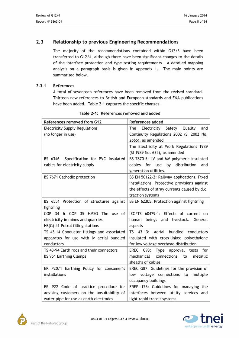
A total of seventeen references have been removed from the revised standard.
Thirteen new references to British and European standards and ENA publications
have been added. Table 2-1 captures the specific changes.
Table 2-1: References removed and added
References removed from G12 References added
Electricity Supply Regulations
(no longer in use)
The Electricity Safety Quality and
Continuity Regulations 2002 (SI 2002 No.
2665), as amended
The Electricity at Work Regulations 1989
(SI 1989 No. 635), as amended
BS 6346 Specification for PVC insulated
cables for electricity supply
BS 7870-5: LV and MV polymeric insulated
cables for use by distribution and
generation utilities.
BS 7671 Cathodic protection BS EN 50122-2: Railway applications. Fixed
installations. Protective provisions against
the effects of stray currents caused by d.c.
traction systems
BS 6551 Protection of structures against
lightning
BS EN 62305: Protection against lightning
COP 34 & COP 35 HMSO The use of
electricity in mines and quarries
HS(G) 41 Petrol filling stations
IEC/TS 60479-1: Effects of current on
human beings and livestock. General
aspects
TS 43-14 Conductor fittings and associated
apparatus for use with lv aerial bundled
conductors
TS 43-13: Aerial bundled conductors
insulated with cross-linked polyethylene
for low voltage overhead distribution
TS 43-94 Earth rods and their connectors
BS 951 Earthing Clamps
EREC C93: Type approval tests for
mechanical connections to metallic
sheaths of cables
ER P20/1 Earthing Policy for consumer’s
installations
EREC G87: Guidelines for the provision of
low voltage connections to multiple
occupancy buildings
ER P22 Code of practice procedure for
advising customers on the unsuitability of
water pipe for use as earth electrodes
EREP 123: Guidelines for managing the
interfaces between utility services and
light rapid transit systems

Review of G12/4 16 January 2014
Report No 8863-01 Page 9 of 34
8863-01-R1 Ofgem G12-4 Review.docx
References removed from G12 References added
ER P23 Consumers earth fault protection for
compliance with the IEE Wiring Regulations
for Electrical Installations
BS 7909: Code of practice for temporary
electrical systems for entertainment and
related purposes
ER P25 The short-circuit characteristics of
Public Electricity Suppliers low voltage
distribution networks
BS EN 50122-1: Railway applications. Fixed
installations. Protective provisions relating
to electrical safety and earthing
ET 113 Notes of guidance for the protection
of private generating sets for operation in
parallel with Electricity Board Distribution
Networks
EREC G83: Recommendations for the
connection of type tested small-scale
embedded generators (up to 16A per
phase) in parallel with low voltage
distribution systems
ER G39/1 Model code of practice covering
public lighting and other street furniture
ER P04/1 Services to BT pubic telephones
2.3.2 Definitions
The revised G12/4 now includes a chapter of definitions at the beginning of the
standard, as is customary for all recent ERECs. The majority of the definitions in
G12/4 are taken from the Electricity Safety, Quality and Continuity Regulations
(ESQCR) and the Wiring Regulations BS 7671. Four new definitions are introduced
as follows:
1. Aerial Bundled Conductor (ABC)
The acronym ABC is used in several places throughout the document. It was
commented by respondants to the consultation that readers may not be familiar
with this acronym and so the inclusion of a definition is helpful.
2. Branch
A branch and service line are now defined, as these are critical to the
requirements of Protective Neutral Bonding as specified in Section 4.11 of the
DNOs’ report.
3. Protective Neutral Bonding (PNB)
The definition of PNB appears to have changed in the revision of this document.
G12/3 (1995) includes the following interpretation (definition):
PNB refers to the technique of using the supply neutral conductor directly from
the transformer to provide a protective earthing facility to a single customer.
The neutral is earthed at one point only normally at or adjacent to the
customer’s installation.
Instead G12/4 includes the following definition:

Review of G12/4 16 January 2014
Report No 8863-01 Page 10 of 34
8863-01-R1 Ofgem G12-4 Review.docx
PNB refers to the situation where there is only one point in a network at which
consumers’ installations are connected to a single source of voltage. In such a
case, the supply neutral conductor connection to earth may be made at that
point or at another point nearer to the source of voltage.
According to this new definition:
The number of customers’ installations is no longer limited to one;
The point of earthing can be at a distance (not specified in the definition)
from the customers’ installations.
4. Caravan
The definition of a Caravan is not taken from BS 7671, although this does include a
separate definition. In general, however, the essence of the wiring regulations
definition is carried through to the G12/4 definition. The G12/4 definition is
wider, as it also includes mobile and residential park homes.
2.3.3 Substation Earthing
The requirement that the HV and LV earths must be segregated if the combined
earth impedance exceeds 1 ohm has been dropped as this was a requirement of
the 1988 Electricity Supply Act. The need to segregate the systems is now based
on the Rise of Earth Potential (ROEP), which can be calculated by undertaking
earthing studies for a specific site. The maximum ROEP of 430V is consistent with
EA TS 41-24.
2.3.4 Cross Sectional Area of Neutral Conductor
For single phase and split phase, the revised G12/4 now introduces specific
minimum cross sectional areas for the neutral conductor of:
10mm2 for copper conductors
16mm2 for aluminium conductors
These reflect the minimum size of main protective bonding conductors for PME
supplies given in Table 54.8 of BS 7671. Previously, the only requirement was that
the CSA of the neutral conductor was not less than that of the phase conductor.
2.3.5 Branches and Service Lines
A branch is defined as a sub-division of a distributing main from its end furthest
from the source of voltage to its junction with the distributing main.
G12 states that a branch may be classified as a service line provided that:
it connects no more than four consumers’ installations, of which one or
more has a PME earthing terminal; and

Review of G12/4 16 January 2014
Report No 8863-01 Page 11 of 34
8863-01-R1 Ofgem G12-4 Review.docx
it is no more than 40 metres in length from its point of connection to the
distributing main.
Figure 4.4 includes one case of a service line dedicated to a single customer’s
installation with “no maximum length”. This seems to contradict the limit of 40m
given in section 3.2 for a service line.
2.3.6 Values of Earth Electrode Resistance
The requirement for LV earth electrodes to have sufficiently low resistance so
that HV protection operates correctly has been carried forward, but reference to
a specific maximum value of 40 Ohms has removed. As a result, earthing studies
will need to be performed in accordance with EA TS 41-24. This is more
appropriate given the possible variation of local soil conditions.
2.3.7 Electrode Seperation Distance
The minimum separation distance between any two electrodes has been increased
from 3m or the depth of the electrode to two times the depth of the electrode.
This now aligns with guidance in BS 7430.
2.3.8 Size of Bonding connections
The minimum size of bonding connection to link boxes and network feeder pillars
and the connection between the cable sheath and neutral conductor at a SNE or
CNE cable joint has been increased from 16mm2 copper to 32mm2 copper.
This change does not appear to be directly taken from BS 7670; however, it is in
line with the trend of increased CSA requirements for earthing conductors not
protected against corrosion.
2.3.9 Protective Neutral Bonding (PNB)
G12 states that PNB may be adopted if the number of consumers and their
distance from the connection to earth meet the same restrictions as those applied
to a branch. However, the definition of a branch included in section 3.2 only
include restrictions for a branch that can be classified as a service line.
Section 3.2 specifies the maximum length of a service line from its point of
connection to the distributing main (but this is not a distance from the connection
to earth as implied in 4.11). Therefore, the reference made in section 4.11 to
section 3.2 could lead to misinterpretations.
It is suggested that in order to avoid misunderstandings, section 4.11 should
include the following restrictions:
Maximum number of customers’ installations;
Distance between the common connection point of the customers’
installations and the supply substation;

Review of G12/4 16 January 2014
Report No 8863-01 Page 12 of 34
8863-01-R1 Ofgem G12-4 Review.docx
If the number of customers’ installations is limited to 4 and the length of the
distance between the common connection point of the customers’ installations
and the supply substation is limited to 40m then this can be considered as
equivalent to Case B shown in Figure 4.4.
2.3.10 Conditions for consumers with existing SNE earth
Historically, many distributed networks contained Seperate Neutral and Earth
(SNE) conductors when G12/3 was published in 1995. Section 5 now makes
provision for customers with SNE installations on a network where a Combined
Neutral and Earth (CNE) cable is introduced. The remaining condition on SNE
installations is that the neutral is continuous back to the supply substation and
therefore the currents are returned to the substation. The metallic sheath of the
cable must have sufficiently low resistance to control the rise of potential to
acceptable levels under open circuit conditions.
It is stated that this criterion will be met provided the resistance to earth of the
sheath or individual earth electrode is 20 ohms or less. This guidance value has
been increased from 10 ohms to 20 ohms. One danger with this approach is that
the 20 ohm value is taken to be the default value and that the rise of potential is
not calculated and proved to be safe.
It is the consultants’ view that in the event of a neutral break the 20 ohm value
will not be sufficient to cause the operation of protection devices other than
residual current circuit breakers which at the time of SNE installations were not a
requirement under BS7671 and the pre-dating IEE Wiring Regulations. Also, the
voltage produced on the earth under these conditions has the potential to exceed
the safe touch voltages within BS EN50522 with no disconnection time.
In comparison with the PME condition, Section 4.7 specifies the earth resistance
applicable to PME systems as compliant with ENATS 41-24 and not exceeding 20
ohms. Section 5.2.1 excludes the option of providing a PME earth if the
installation is not designed to BS7671. BS7671 has addressed earthing issues
historically by the use of supplementary bonding and within the existing
regulations by the requirement for residual current devices. The combination of
the 20 ohm requirement within the supply network and the BS7671 requirements
within the installation would require a dual failure within the overall system
before a dangerous voltage would have the possibility of causing harm.
Therefore, it is difficult to see how the 20 ohm resistance value in section 5.1 can
provide safety in the event of a neutral failure. We would need to examine any
evidence that the authors of this revision may have to support the following
statement included in Section 5.1:
“By experience this criterion will be met provided the resistance to earth of the
metallic sheath is 20 ohms or less or an individual earth electrode is provided
with a resistance of less than 20 ohms”

Review of G12/4 16 January 2014
Report No 8863-01 Page 13 of 34
8863-01-R1 Ofgem G12-4 Review.docx
If this evidence is not available we would suggest excluding the ‘’By experience
this criterion will be met ... 20 ohms’’ clause hence leaving only the ‘’sufficient
to limit the rise of potential under open circuit neutral conditions’’ clause.
2.3.11 Labels and Notices
Section 5.4 currently suggests that installers should label the service position at a
consumer’s installation where PME services are available. It was raised in one
response to the consultation documents that this should be mandatory practice,
and the should replaced with shall. In the interest of good safety practice it is
suggested by the consultants that this practice could be made mandatory, and the
should replaced with shall.
2.3.12 Special Situations
This section now includes an explanation of the potential dangers of PME earthing,
if adopted in unsuitable locations or situations. This is a helpful addition as it
reinforces the need for clear guidance as given in this EREC.
2.3.13 Traction Applications
This section has been entirely revised in order to differentiate between the
requirements of:
AC electrified traction systems;
DC electrified traction systems;
Sites with both AC & DC traction systems.
Previously, a fixed limt of the acceptable voltage (25 volts) on the return path of
the traction system was applied in all three cases with little or no guidance as to
how compliance with this limit could be ensured.
AC electrified traction systems
The 25 volt limit is retained, but in addition it is made clear that an earthing
study must be performed or design standards must ensure that the rise of earth
potential must also be limited to the acceptable values as specified by TS 41-24.
The critical values are incorporated into G12/4 for easy reference.
Rail electrical safety standard BS EN 50122-1 and Low Voltage Power Supplies
standard GL/RT1255 were specifically referenced in the consultation draft, but
responses from the Railway Safety and Standards Board raised concerns that as
these standards do not apply uniformly across all rail sectors, reliance on them for
compliance could be misleading. In response, the WG has removed direct
reference to them in this section; however they remain referenced in the NOTE
for information.
DC electrified traction systems
Review of G12/4 16 January 2014
Report No 8863-01 Page 14 of 34
8863-01-R1 Ofgem G12-4 Review.docx
The 25 Volt limit is not retained in relation to DC traction systems. Instead it is
specified that for a PME supply to be provided, neither pole of the traction system
may be directly connected to earth, and the rails or conductors are adequately
insulated from earth. BS EN 50122-2 is now referenced as the relevant rail
standard to ensure adequate protection from DC stray currents and that no
voltage is picked up by the neutral/earth at the point of supply.
It is noted in G12/4 that these requirements are based on the recognition that any
stray currents that do exist should become quickly apparent to the railway
operator through regular inspections of structures and earthing systems, as more
current will flow through these elements than the DNO LV earthing system.
This is considered to be a reasonable approach, as there is now an increased
understanding of the electrolytic corrosion caused by DC currents, and so the
regular inspection of current paths for signs of corrosion is common practice. In
BS EN 50122-2, provisions are even given for the continous monitoring of rail
potential, to assess stray current.
Sites with both AC & DC traction systems
This requirement has been simplied significantly, as G12/4 now simply states that
a PME earth terminal shall not be provided if a site has both AC and DC traction
systems.
It is clear that the revised G12/4 offers improved guidance for DNOs about the
safe and acceptable conditions under which a PME earth can be supplied to
traction customers. This was a key driver for change in the review process.
2.3.14 Construction and Demolition Sites
It is acknowelged that the requirements of a PME system are not generally
practical on construction sites; however G12/4 now includes guidance on the
types of earthing system that would be acceptable instead. Two options have
been included:
1. TN-S supply from a dedicated transformer
2. TT supply with RCD protection
In the consultation draft, a third option was also presented, providing a TN-S
supply via an isolation transformer. This option was removed following responses
to the consultation which highlighted that an isolation transformer is not required,
as the protective separation provided by an isolating transformer can also be
provided by a suitable power transformer.
It is suggested by the Consultants that the isolation transformer is still a valid
solution and provides a useful additional option in the case that there is no
dedicated power transformer on site. . It is suggested the wording of an isolating
transformer be removed however to reflect an isolating tranfomer or power
transformer could be used.

Review of G12/4 16 January 2014
Report No 8863-01 Page 15 of 34
8863-01-R1 Ofgem G12-4 Review.docx
It is suggested with the reintroduction of this section, 6.2.2.3 it will also be
required to re-word the requirements of voltage rise. In line with the previous
user comments it is suggested the wording ‘the voltage rise on the site earth is
less that 50V’ is replaced with ‘the product RA x I∆n is less than or equal to 50 V,
as required by BS 7671’.
2.3.15 Swimming Pools
The guidance for the provision of PME to buildings and locations containing
swimming pools and other basins has been expanded to provide “Competent
persons enquiring about the suitability of PME for swimming pool supplies”.
The following guidance suggests that it is acceptable to provide a PME supply and
it is then the electrician’s decision as to whether or not to utilise the PME
terminal for all or part of the installation. It is further explained that it is
acceptable to use a PME earthing system, TT system or combination of these
systems, depending on the exact arrangements and segregation of the pool
installation within the location.
The references to BS 7671 are slightly confusing with regard to the TT system and
requirements for RCDs. In general, this topic is specified well in BS 7671, Section
702, and it is considered that the wording on this section could be simplified by
referring to BS 7671 for full installation details, in order to avoid ambiguities
between G12/4 and BS7671.

Review of G12/4 16 January 2014
Report No 8863-01 Page 16 of 34
8863-01-R1 Ofgem G12-4 Review.docx
2.4 Interface with Distribution Code provisions
The Distribution Licence conditions require the Distribution Code to satisfy various
requirements in respect of Low Voltage Networks as given in Table 2-2:
Table 2-2: Distribution Licence Condition Requirements
Licence condition requirements Discussion in respect of LV Network Earthing
The Code must cover all material technical aspects relating to connections to and the operation and use of the licensee’s Distributions System or (so far as is relevant to such operation and use) the operation of electric lines and electrical plant connected to that system.
G12/4 is referenced by The Distribution Planning and Connection Code (DPC). G12/4 covers the License condition requirement for the DNO to provide such information, as may be reasonably required, on the design and other characteristics of the DNO’s Distribution System.
The Code must include a Distribution Planning and Connection Code that must contain:
Planning conditions that specify the technical and design criteria and procedures that are to be applied by the licensee in the planning and development of its distribution system and taken into account by persons having a connection or seeking a connection to that system in the planning and development of their own plant and systems;
Connection conditions that specify the technical, design and operational criteria to be complied with by any person having a connection or seeking a connection to the licensee’s distribution system.
G12/4 covers the design practice for Protective Multiple Earthing, as it affects connection conditions.
The Code must be designed (so far as is consistent with the first two requirements) to:
Permit the development, maintenance and operation of an efficient, co-ordinated and economical system, for the distribution of electricity; and
Facilitate competition in the generation and supply of electricity
G12/4 provides guidance to Connectees and Distribution Network Operators (DNOs) regarding the requirements for the application of protective multiple earthing to low voltage networks to enable this licence requirement to be met.
In the process of revising G12/3, some editoral changes have been made to the
Distribution Code. These changes have been presented in the Report to the
Authority (Appendix 3). The issue summary at the end of the Distribution Code
summarises the revisions between versions. The change required for the proposed
G12/4 is cited as being:
Replace G12/3 with G12/4 in Annex 1, DPC4.3.2 - Design Principles, DPC4.4.2 -
Earthing
Review of G12/4 16 January 2014
Report No 8863-01 Page 17 of 34
8863-01-R1 Ofgem G12-4 Review.docx
As noted in the Report to the Authority (section 5.2), the changes replacing the
references to G12/3 are editorial, and do not have any impact on the
interpretation of the Code.
2.5 Errors in diagrams and typographical mistakes
There were no editorial errors and typographical mistakes identified in G12/4
during the course of this review.
2.6 Compliance of ER G12/4 with Electricity Act objectives
A key requirement of ER G12/4 is that it supports Ofgem in meeting its obligations
under the Electricity Act; any conflicts between the recommendations of ER
G12/4 and Ofgem’s obligations are therefore to be avoided.
The most relevant of Ofgem’s duties to the areas of activity covered by G12/4
are:
To promote competition in the generation and supply of electricity – Section
3A(1) of the Act; and
To protect the public from dangers arising from the generation,
transmission or supply of electricity – Section 3(5)(b).
Note that the Electricity Act, when originally enacted, contained a duty on the
Authority to protect the interest of consumers in respect of quality of supply
(Section 3(3)(a)(iii)). This clause is not in the revised Section 3A of the Electricity
Act; the revisions to the duties of the Authority were set out in the Utilities Act
2000. The quality of supply is covered by the licence obligations of the DNOs.
ER G12/4 has an important role to play in the second of these areas, for a number
of reasons:
Provisions for the earthing of low voltage networks are crucial to maintain
the safe operation of the distribution networks and thus to protect the
public adequately.
In the majority of areas the new Engineering Recommendation G12/4 is
considered to deliver all of the above requirements. Where there were concerns
in specific areas, these have been highlighted in this report and are summarised in
Section 0 below.

Review of G12/4 16 January 2014
Report No 8863-01 Page 18 of 34
8863-01-R1 Ofgem G12-4 Review.docx
3 Conclusions
3.1 Suitability of ER G12/4 for replacing G12/3 under the Distribution
Code
It is the Consultants’ view that a reasonable balance of comments was submitted,
the majority of which have been accepted by the Working Group. There were no
comments recieved from DNOs or Network Rail, however both these groups were
represented fully on the Working Group.
Following the WG consideration of and response to the recommendations in
Section 0 below, G12/4 removes a number of inconsistencies and shortfalls which
were present in G12/3 and generally provides a simpler, more standardised
approach to the connection of SSEG.
Section 3.3 summarises the issues that were considered by the Consultants to be
critical to the compliance of G12/4 with the objectives set out in the Terms of
Reference. Section 0 contains additional suggestions for areas of improvement,
but these points are not critical to the suitability of ER G12/4 for replacing G12/3.
3.2 Compliance of ER G12/4 with Electricity Act objectives
The new Engineering Recommendation G12/4 is considered to meet all of the
above requirements and is consistent with the Authority’s principal objectives
under The Electricity Act.
3.3 Critical Recommendations
These issues were considered by the Consultants to be critical to the compliance
of G12/4 with the objectives set out in the Terms of Reference.
These recommendations have now been discussed with the working group and
their comments and final responses are included below. The consultants are
satisfied by the final responses of the working group that each of these issues has
been resolved.
3.3.1 Protective Neutral Bonding (PNB)
G12/4 states that PNB may be adopted if the number of consumers and their
distance from the connection to earth meet the same restrictions as apply to a
branch. However, the definition of a branch included in section 3.2 only includes
restrictions for a branch that can be classified as a service line.
Section 3.2 specifies the maximum length of a service line from its point of
connection to the distributing main (but this is not a distance from the connection
to earth as implied in 4.11). Therefore, the reference made in section 4.11 to
section 3.2 could lead to misinterpretations.

Review of G12/4 16 January 2014
Report No 8863-01 Page 19 of 34
8863-01-R1 Ofgem G12-4 Review.docx
It is suggested that in order to avoid misunderstandings, section 4.11 should
include the following restrictions:
Maximum number of customers’ installations
Distance between the common connection point of the customers’
installations and the supply substation
Working Group proposed wording: “PNB may be adopted if the number of
consumers is 4 or less and their distance from the connection to earth is 40m or
less.
The LV neutral conductor shall be connected to an earth electrode at a point
remote from the transformer, between the transformer and the supply terminals
of the consumer(s). The distance between the connection to earth and the
consumers’ intake shall be 40m or less; however in order to minimise the risk of
voltage rise in the event of a broken neutral this connection should be made as
close as is practicable to the consumers’ supply terminals. The metallic sheaths
of any LV cables shall also be connected to the earth electrode. The resistance
of the earth electrode shall not exceed 40 ohms”
This change is accepted by the consultants.
3.3.2 Conditions for consumers with existing SNE earth
One of the conditions for SNE installations remaining on a network where a
Combined Neutral Earth (CNE) cable is introduced is that the metallic sheath of
the cable has sufficiently low resistance to control the rise of potential to
acceptable levels under open circuit conditions.
It is stated that this criterion will be met provided the resistance to earth of the
sheath or individual earth electrode is 20 ohms or less. One danger with this
approach is that the 20 ohms is taken as the default value and the rise of
potential not calculated and proved to be safe.
It is the consultant’s view that In the event of a neutral break the 20 ohm value
will not be sufficient to cause the operation of protection devices other than
residual current circuit breakers which at the time of SNE installations were not a
requirement under BS7671 and the pre-dating IEE Wiring Regulations. Therefore it
is difficult to see how the 20 ohm in section 5.1 can provide safety in the event of
a neutral failure.
The Consultants would need to examine any calculations/earthing model/site
measurements that the authors of this revision may have to support the following
statement included in the referred section:
“By experience this criterion will be met provided the resistance to earth
of the metallic sheath is 20 ohms or less or an individual earth electrode is
provided with a resistance of less than 20 ohms”

Review of G12/4 16 January 2014
Report No 8863-01 Page 20 of 34
8863-01-R1 Ofgem G12-4 Review.docx
If these calculations are not available, the Consultants would suggest excluding
the ‘By experience this criterion will be met ... 20 ohms’ clause hence leaving
only the ‘sufficient to limit the rise of potential under open circuit neutral
conditions’ clause.
Working Group proposed wording: “By experience this criterion will be met
provided the resistance to earth of the metallic sheath is 10 ohms or less or an
individual earth electrode is provided with a resistance of less than 10 ohms.
Where in specific circumstances the 10 ohm value cannot be achieved, a value of
up to 20 ohms is acceptable where it can be shown by calculation that any voltage
rise on the neutral conductor of the 3 phase cable is limited to 100V.”
This change is accepted by the consultants.
3.3.3 6.2.5 Swimming Pools and other basins
As this topic is well specified in BS 7671, Section 702, it is suggested that the
wording in this section can be simplified as follows in order to avoid ambiguities
between G12/4 and BS7671.
It is the suggestion of the Consultants to replace all text by the following
paragraph:
“Locations containing swimming pools and other basins are considered to be
‘Special Locations’ within BS 7671, Section 702. The electrical installation, the
supply system and the earthing system shall comply with the requirements
included in BS7671, Section 702.”
Working Group proposed wording:
“NOTE: This Section is for guidance of Network Operators only.
(continue with existing text)”
This change is accepted by the consultants.

Review of G12/4 16 January 2014
Report No 8863-01 Page 21 of 34
8863-01-R1 Ofgem G12-4 Review.docx
3.4 Additional Recommendations
These recommendations are not critical to the suitability of ER G12/4 for
replacing G12/3; however the Consultants suggest that they are considered by the
WG.
3.4.1 Labels and Notices
Section 5.4 currently suggests that installers should label the service position at a
consumer’s installation where PME services are available. It was raised in one
response to the consultation documents that this should be mandatory practise,
and the should replaced with shall. In the interest of good safety practice it is
suggested by the consultants that this practice could be made mandatory, and the
should replaced with shall.
Working Group proposed wording: “Where PME facilities are available to a
consumer, a label shall be affixed at the service position drawing attention to the
fact that the service is connected to a network having protective multiple
earthing.”
This change is accepted by the consultants.
3.4.2 Installation of Electrodes along branches
Figure 4.4 includes one case of a service line dedicated to a single customer’s
installation with “no maximum length”. This seems to contradict the limit of 40m
given in section 3.2 for a service line. It is the consultant’s suggestion that the
working group address this apparent conflict, by including the maximum length.
Working Group response: We do not feel a change is necessary to the existing
Figure 4.4.
The working group has clarified that there is no maximum length for a service
line, only upon branches classed as service lines. This explanation is accepted by
the consultants.
3.4.3 Construction and Demolition Sites
In the consultation draft, the options were presented for earthing arrangements
on construction and demolition sites. One of these options was to provide a TN-S
supply via an isolation transformer. This option was removed following responses
to the consultation which questioned the need specifically for an isolating
transformer.
The Consultants’ view is the comments were not correctly interpreted by the
working group. The comments suggest that it is not specifically an isolation
transformer which is needed and in fact any power transformer could be used
provided the required voltage for the site is provided by the power tranformer.

Review of G12/4 16 January 2014
Report No 8863-01 Page 22 of 34
8863-01-R1 Ofgem G12-4 Review.docx
It is suggested by the Consultants that the isolation transformer is still a valid
solution and provides a useful additional option in the case that there is no
dedicated power transformer on site. . It is suggested the wording of an isolating
transformer be removed however to reflect an isolating tranfomer or power
transformer could be used.
It is suggested with the reintroduction of this section, 6.2.2.3 it will also be
required to re-word the requirements of voltage rise. In line with the previous
user comments it is suggested the wording:
‘the voltage rise on the site earth is less that 50V’
is replaced with
‘the product RA x I∆n is less than or equal to 50 V, as required by BS 7671’.
Working Group proposed wording:
“The following sections specify the types of earthing systems that can be used for
temporary construction and demolition site supplies. As it is usually impractical
to comply with the bonding requirements of BS 7671, a PME supply should not be
offered, except for the supply to a fixed building of the construction site. The
following sections specify the types of earthing system that can be used.
In addition to the arrangements shown in 6.2.2.1 and 6.2.2.2, if the site does not
have a dedicated transformer, ie the transformer supplies other consumers or
other parts of the LV network, it is still possible to provide a TN-S earthing system
within the boundary of the site via a suitable isolating transformer.
The transition from a temporary to a permanent supply must be taken into
account, and both supplies should be considered during the design and planning
stages. Refer also to BS 7375.”
This change is accepted by the consultants.
Review of G12/4 16 January 2014
Report No 8863-01 Page 23 of 34
8863-01-R1 Ofgem G12-4 Review.docx
Appendices
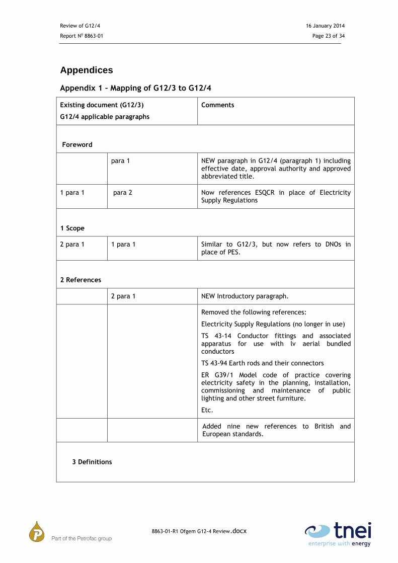
Appendix 1 – Mapping of G12/3 to G12/4
Existing document (G12/3)
G12/4 applicable paragraphs
Comments
Foreword
para 1 NEW paragraph in G12/4 (paragraph 1) including effective date, approval authority and approved abbreviated title.
1 para 1 para 2 Now references ESQCR in place of Electricity Supply Regulations
1 Scope
2 para 1 1 para 1 Similar to G12/3, but now refers to DNOs in place of PES.
2 References
2 para 1 NEW Introductory paragraph.
Removed the following references:
Electricity Supply Regulations (no longer in use)
TS 43-14 Conductor fittings and associated apparatus for use with lv aerial bundled conductors
TS 43-94 Earth rods and their connectors
ER G39/1 Model code of practice covering electricity safety in the planning, installation, commissioning and maintenance of public lighting and other street furniture.
Etc.
Added nine new references to British and European standards.
3 Definitions

Review of G12/4 16 January 2014
Report No 8863-01 Page 24 of 34
8863-01-R1 Ofgem G12-4 Review.docx
New Section Added significant number of defined terms.
Comments on individual terms have been captured in the Review of the Report to the Authority and editorial comments.
4. Requirements for PME Networks
4.1 4.1 No Change
4.2 4.2 The requirement to segregate if the combined impedance exceeds 1 ohm has been dropped as this was a requirements of the 1988 Electricity Supply Act.
4.3.2 4.3 Re-worded to include all protective devices
4.3.1 para 1 4.3.1 para 1 No change
4.3.1 para 2 4.3.1 para 2 Minimum CSAs for the supply neutral added
New NOTE Note to describe terms “single phase 3 wire” and “split phase”
4.3.3 para 1 4.3.2 para 1 No change
4.3.3 para 2 4.3.2 para 2 Specific requirements about compression joints etc. removed
4.3.3 para 3 4.3.2 para 3 No change
4.4.1 4.4.1 para 1 Fixed maximum resistance to earth at any point on the neutral of 20 Ohms has been REMOVED.
4.4.1 para 2 New requirement to install a neutral/earth electrode at the boundary point between network operators.
4.4.2 4.4.2 Relaxation of earth requirements for a ‘branch’ is now restricted to those classified as ‘service lines’
4.5 4.5 para 1 No change
4.5.1 4.5 para 2 No change
4.5.2 4.5 para 3 No change
4.5.3 4.5 para 4 Wording changed to clarify requirement to bond earth and neutral on remote sections of SNE distributing mains in order to convert to PME.
4.5.4 para 1 4.5 para 5 No change

Review of G12/4 16 January 2014
Report No 8863-01 Page 25 of 34
8863-01-R1 Ofgem G12-4 Review.docx
Fig 1 Fig 4.4 Diagram moved from end of document to relevant place in text.
Fig 2 Fig 4.5 Diagram moved from end of document to relevant place in text.
4.5.4 para 2 4.5 para 6 No change
4.6 para 1 4.6 para 1 No change
4.6.1 REMOVED
4.6.2 4.6 para 2 No change
4.6.3 4.6 para 3 20 Ohm maximum resistance requirement moved to section 4.7
Note Note 1 No change
Note 2 NEW comment
4.6.4 4.6 para 4 No change
4.6.5 4.6 para 5 No change
4.8.1 4.7 40 Ohm substation neutral earth resistance requirement has been REMOVED. Instead values in TS 41-24 are referenced. 4.8.2 REMOVED
4.8.3 4.7
4.8.4 REMOVED Assumption that overall resistance is equivalent to individual electrode resistances in parallel has been REMOVED.
4.7 para 1 4.8 para 1 No change
4.7 para 2 4.8 para 2 Separation distances between electrodes changes from 3m or 1x electrode depth to 2 x electrode depth.
4.9 para 1 4.9 para 1 No change
4.9 para 2 4.9 para 2 Wording change and reference to table updated
4.9 para 3 NEW guidance that it is not acceptable to use short-time equivalent ratings in calculating the required CSA of a PME earthing conductor.
Table Table 4.9a Minimum copper equivalent CSA for Bonding connection to link boxes and feeder pillars, and connections between sheath of SNE cable and neutral of CNE cable INCREASED to 32mm2

Review of G12/4 16 January 2014
Report No 8863-01 Page 26 of 34
8863-01-R1 Ofgem G12-4 Review.docx
4.9 para 4 NEW table included to cover equivalent copper CSA for commonly used Al DNO incoming cables
Table 1 Removed Bonding connection between earthing terminal and metal structures and pipes in customers installation now dealt with in Wiring Regulations.
4.10 4.10 Removed reference to 1 Ohm resistance (same reason as 4.2)
4.11 NEW section on Protective Neutral Bonding
See section 3 for full discussion
5 Customers’ Installations
Section 5 Section 5 Consumers to replace “Customers” in heading
5.1 para 1 5.1 para 1 No change
5.1 para 2 5.1 para 2 Re-formatted for clarity
New standard reference IEC/TS 60479-1
Invdividual electrode max resistance INCREASED from 10 Ohms to 20 Ohms
5.1 para 3 5.1 para 3
5.1 para 4 5.1 para 4 Resistance to earth of metallic sheath of SNE cable INCREASED from 10 ohms to 20 ohms
5.1 para 5 5.1 para 5 No change
5.2.1 NEW simplified conditions for when a PME earth terminal CANNOT be offered to consumers.
5.2.1 5.2.2 No change
5.2.2 5.2.3 Reference to BS5951 has been replaced by EREC C93
5.3 REMOVED Requirement for equipotential bonding is covered in compliance with the wiring regulations
5.4 5.3 No change
5.5.1 REMOVED Comment regarding Neutral Links not being removed has been deleted.
5.5.2 5.4 No change

Review of G12/4 16 January 2014
Report No 8863-01 Page 27 of 34
8863-01-R1 Ofgem G12-4 Review.docx
6 Special Situations
6.1 6.1 Para 1 New explanation of impact of PME in unsuitable situations added
6.1.1 6.1 Para 2 No change
6.1 Para 3 NEW –
6.2 6.2 NEW introduction – adding that this list of special situations is not exhaustive
6.2.1 6.2.1 This section has been entirely revised to differentiate between the requirements of:
General
AC electrified traction systems
DC electrified traction systems
Sites with both AC & DC traction systems
6.2.2 6.2.2 This section has been revised to include additional guidance on the types of earthing system that can be used on a construction site (as PME is not usually practical)
TN-S from dedicated transformer
TT with RCD protection
Transition to permanent supply
6.2.3 6.2.3 Revised to specifically to preclude the use of PME with exhibition stands, temporary structures at fairs and mobile or transport units.

Review of G12/4 16 January 2014
Report No 8863-01 Page 28 of 34
8863-01-R1 Ofgem G12-4 Review.docx
Appendix 2 – Consultants’ Response to Working Group comments
It was noted that in comparison with previous consultations, the WG gave an
explanation for rejecting comments, rather than simply stating that they have
been rejected. This was extremely helpful for the review process.
Comments from the consultation responses that have not been accepted are
detailed in Table A.2.
Technical comments with more than one comment on the same issue are
discussed below.
Street Electrical Fixtures with load of 500kW and over
Three independent respondents raised concern that the limit of 500kW was
arbitrary and that there should be some latitude for small increases in load above
this level without the requirement to re-design the earthing of the installation.
All three comments were not accepted on the basis that the 500kW limit
corresponding to a 100 Ohm minimum electrode resistance can be calaculated to
give the same voltage rise as a 2 kW load with a 20 ohm earth electrode. This is a
legitimate engineering comparison and importantly maintains a safe level of rise
of earth potential.
In addition the working group have clarified the requirements by illustrating the
necessary maximum electrode resistance for a range of loads from 500w to 5kW,
illustrating the relationship between electrical load and resistance to earth in
order to maintain a safe level of potential voltage rise.

Review of G12/4 16 January 2014
Report No 8863-01 Page 29 of 34
8863-01-R1 Ofgem G12-4 Review.docx
Table A.2 Consultants Response to Consultation Responses which were rejected by the Working Group
Stakeholder Clause/
Subclause Type of comment
(General/
Technical/
Editorial)
COMMENTS Proposed change OBSERVATIONS OF THE SECRETARIAT
on each comment submitted
UKLB 2 G The UK lighting board (UKLB) agree that there has in
the past been a lack of consistency in the type of
connection provided at similar sites to due to differing
interpretations of the existing requirements by different
DNO engineers. From that perspective the UKLB
welcome an initiative to clarify the regulations.
Suggest this section identifies the benefits to all
consumers (and not just ‘Rail’) of these
amendments
Not accepted. The benefits are in improved
guidance on special situations; update the
documents in line with changes in standards since
the last revision and closer alignment with the IET
wiring regulations.
UKLB 2 G There is no economic appraisal of this revision. Will UK
plc benefit overall? What are the projected additional
costs for DNOs and customer?
There should be an economic appraisal of the
revision such that there is clarity about the
changes in terms of overall cost and the cost to
individual parties. This should form part of an
sustainability assessment
Not accepted. There have been no significant
changes to the technical requirements so the
revision is cost neutral.
UKLB 2 G There is no environmental appraisal of this revision.
Will implementation require more or less materials? (I
am assuming line losses will remain constant, but this
should also be assessed from a Carbon emissions point
of view|)
There should be an environmental appraisal of
the revision such that there is clarity on the
environmental impact of the proposed changes.
This should form part of an sustainability
assessment
Not accepted. There have been no significant
changes to the technical or material requirements
with the result that the revision does not have an
environmental impact.
UKLB 2 G There is no societal impact appraisal of this revision.
Will implementation result in a greater or reduced level
of safety overall. (From a UKLB perspective, there is a
concern that consideration has not been given to the
possibility there may be an overall increase in risk to our
workforce, see below)
There should be a societal impact appraisal of
the revision such that there is clarity on the
overall safety impact of the proposed changes.
This should form part of an sustainability
assessment
Not accepted. There have been no significant
changes to the technical or installation
requirements with the result that the revision does
not have social impact
ESC 2 E Remove reference to edition to future-proof document Delete ‘Seventeenth Edition’ Not accepted, 17th edition contained the current
regulations at the time of the review

Review of G12/4 16 January 2014
Report No 8863-01 Page 30 of 34
8863-01-R1 Ofgem G12-4 Review.docx
ESC T You apply a different meaning to the term ‘caravan’ to
that given in BS 7671
Clarify that you use a different definition of
caravan to that used in BS 7671
Not accepted. This is already clarified by the note,
i.e. the definition would have a double asterisk if
taken from BS 7671.
TfL Figure 4.4 technical Since 2003 TfL have installed for all traffic signals an
earth electrode at the feeder pillar to ensure PME
service is made available and to minimise danger to
public.
Include customer earth electrodes on diagrams
and consider the additional contribution towards
safety of a PME network.
Not accepted. Fig 4.4 shows minimum
requirements to be compliant.
ESC Fig 4.5 Line not phase Replace ‘phase’ with ‘line conductor’ to read ‘line
conductor normally open’
Not accepted. See earlier comments on line 205. ESC
ESC 4.9 Table
4.9a
E In row 2 of table, should read line not phase Make ‘line conductor’ Not accepted. See earlier comment on line 205.
ESC The table commences at 35mm – what about smaller
services?
It might be clearer to include a top line saying
“less than 35mm … with 16mm earth”
Not accepted. The current table is aligned with
other reference documents. The table refers to
typical sizes of three-phase cables.
AMO
PDAL
(part)
G Meter Operators frequently find cut-outs which are not
labelled as PME. When ENA asked on ER requirement
the response was that the ER only used the term
“should” which means the distributor does not always
have to place a label. This leaves the method of
earthing available to a customer ambiguous. This is a
serious concern for meter operators who are left
uncertain what type of earthing (if any) is provided to
the customer
On all new and service alterations or cut-out
changes the distributor should always explicitly
label every cut-out to identify the type of
earthing available: CNE, SNE or no earth
available. The meter operator and/or customer
representative can then connect (or not) to the
distributor provided earth connection. This is
particularly important when connecting
customers in ‘special situations’
Not accepted, as this is not considered practical. It
is the policy of most Network Operators to fit a
label. If uncertain of the earthing arrangement, a
competent person should be contacted

Review of G12/4 16 January 2014
Report No 8863-01 Page 31 of 34
8863-01-R1 Ofgem G12-4 Review.docx
TfL 451 Technical This doesn’t mention the UKPN practice of using a
grading electrode to raise the potential of the
surrounding ground thus reducing the touch potential to
the earthed metalwork.
Practically, installing a 70mm2 bare copper electrode
500mm deep and 500 around the perimeter of a feeder
pillar is difficult in a London street. The clause seems
to force the customer to use Class2 feeder pillar to get
PME earth. However, A class 2 pillar will not offer any
safety to earth metalwork beyond the feeder pillar even
if an RCD is used.
Include the practice of using UKPN “grading
electrode” or not
Not accepted. As this is a National Document it
cannot include the practices of all Network
Operators - they will each have their own earthing
policy based on this generic document and tailored
for their specific requirements.
TfL 461 Technical Perhaps traffic signals could be included in special
conditions. It is possible for a traffic signal controller,
being intelligent equipment, to disconnect it load and
reduce the risk of dangerous potential on all associated
earthed metalwork.
ADD
Intelligent equipment.
Where equipment includes voltage monitoring
or similar such that under neutral fault
conditions the connected load may be reduce to
less than 500w in 0.4sec.
Not accepted. Whilst this may be an interesting
technical solution the technology is currently
unproven for use for this specific purpose so it
cannot yet be included in National Documentation
AMO
PDAL
(part)
475 T May wish to make explicit that this applies to cut-out
and meter panels. Meter panels are provided by
distribution businesses.
Clarity requested with regard to bullet (c) – is this with
regard to railways only or in general on every PME
supply position. If general; this is an issue as most
multi-occupancy site positions have metal MSDBs (i.e.
BEMCO, Ryefield) so many sites would not be
compliant.
Include explicit reference to meter panels Not accepted. This is part of sub-clause 6.2.1,
which relates only to railways and tramways.
ESC 568 6.2.2 The word ‘temporary’ seems superfluous Delete the word ‘temporary’ Not accepted. The supply may be for the final
installation or a future one

Review of G12/4 16 January 2014
Report No 8863-01 Page 32 of 34
8863-01-R1 Ofgem G12-4 Review.docx
ESC 6.2.31.1 T The text relating to exhibitions, shows and stands does
not align fully with requirements in Regulation
711.411.4 of BS 7671, which states:
‘Except for a part of an installation within a building,
PME earthing facility shall not be used as the means of
earthing for an installation falling within the scope of
this section except:
(i) Where the installation is continuously under the
supervision of a skilled or instructed person, and
(ii) The suitability and effectiveness of the means of
earthing has been confirmed before the connection is
made.’
Align text with BS 7671 requirement Not accepted. This requirement is in G12/3 and
Network Operators believe the exceptions in (1)
and (ii) are too difficult to implement and
maintain.
ESC 6.2.4 696 E IET Guidance Note 5 is just one of many publications
that provide some guidance
Delete reference to just one specific source of
guidance
Not accepted, as it is the most relevant source of
guidance
AMO
PDAL
824 T May also wish to include a reference to IGE/G/5 – gas
in flats http://www.igem.org.uk/technical-
standards/standards/general.aspx This describes
earthing in respect of gas pipes.
Not accepted, as not deemed necessary.
HEA 861 General The heading makes reference to
electrical load of “500W or less”. This conflicts with
both the strict wording of the relevant SI and the
wording and intent of the NMO Guidance issued in
2012. The key test is predictability of the load - not
whether it is less than 500W
Replace “Street lighting and road signs with
electrical load of 500W or less” with “Street
lighting and road signs with a predictable load”
Not accepted. The 500W limit has been arrived at
through technical considerations and has to remain
an absolute requirement.

Review of G12/4 16 January 2014
Report No 8863-01 Page 33 of 34
8863-01-R1 Ofgem G12-4 Review.docx
UKLB 861 &
916
General Where does the 500W limit come from? Ditto the 2kW
threshold. These have cost implications for consumers,
so some latitude would allow for a more efficient
implementation of objectives. For example, if A LHA
upgrades 5 street lights from circuit watts of 90W to
105W, do I really need to redesign my cable network?
Can the limits be explained and justified?
Can there be some flexibility rather than have
these fixed and absolute limits? This will
facilitate sensible management of the risk in
terms of keeping costs proportional to the risk.
The load and any other earth return path act in
parallel to limit the rise of voltage under broken
neutral conditions. A 20 ohm return path in
parallel with a 2kW load will limit the rise in
voltage to the same value as a 500W load in
parallel with 125 ohms which is the earth
resistance of a typical earth rod in average soil
conditions. The 2kW/20 ohm values were given as
a G12/3 requirement. The earthing design would
need to be reviewed in the scenario suggested.
No change proposed.
PDAL 861 T There is no technical difference as a result of 500W or
in the ESQCR. The reference to 500W should be
removed.
Not accepted. The 500W limit has been arrived at
through technical considerations and has to remain
an absolute requirement.
TfL 866 Technical TfL traffic signal practice is to provide an earth
electrode at the Main Earth Terminal to ensure
minimised danger of potentials on earthed metalwork
where PME service is provided.
ADD - An earth electrode shall be provided at
every feeder pillar supplying Traffic signals and
shall be connected to the Main Earth Terminal.
(to allow for testing) .
Not accepted. It is only relevant if the resistance of
the earth rod is chosen to match the load.
HEA 6.2.14 Technical As written, the document would require an earth
electrode even if only one item of equipment is
connected to another via a distribution cable
Replace “An earth electrode shall be provided at
the end of every service supplying more than
one street lamp or road sign.” with “Earth
electrode(s) shall be provided at the last or
penultimate street lamp or road sign where
necessary to ensure the earth loop impedance
value is satisfactory”
Not accepted, as the existing wording is
considered clear. The requirement for the earth rod
is not primarily to do with the earth loop
impedance.
TfL 898 Technical Diagram 6.2.14b: Reference should be made to a max
2kW based on 6.2.15 if this is intended
ADD
Note load not exceeding 2kW
Not accepted, as the 2kW max limit is not
necessary. Extend table 6.2.15 to add 1kW, 3kW
4kW and 5kW with values of 60,14,11 and 9
ohms.
Add note to Table 6.2.15 to the effect that by
agreement with the Network Operator it may be
permissible to take into account the contribution
from distributed earths in specific situations.
Review of G12/4 16 January 2014
Report No 8863-01 Page 34 of 34
8863-01-R1 Ofgem G12-4 Review.docx
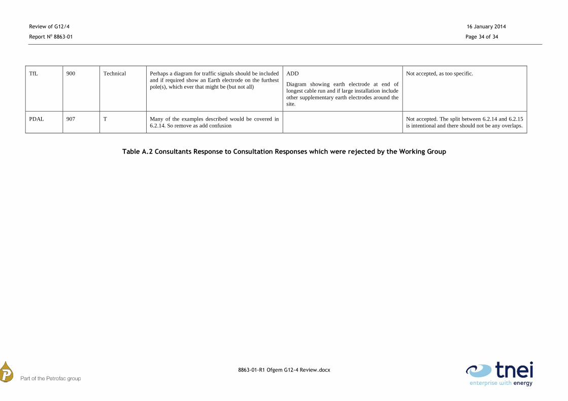
Table A.2 Consultants Response to Consultation Responses which were rejected by the Working Group
TfL 900 Technical Perhaps a diagram for traffic signals should be included
and if required show an Earth electrode on the furthest
pole(s), which ever that might be (but not all)
ADD
Diagram showing earth electrode at end of
longest cable run and if large installation include
other supplementary earth electrodes around the
site.
Not accepted, as too specific.
PDAL 907 T Many of the examples described would be covered in
6.2.14. So remove as add confusion
Not accepted. The split between 6.2.14 and 6.2.15
is intentional and there should not be any overlaps.