Review of CO2/H2-methanation within power-to-gas processes
72
Master Thesis Review of CO 2 /H 2 -methanation within power-to-gas processes carried out for the purpose of obtaining the degree of Master of Science (MSc or Dipl.-Ing. Or DI) submitted at TU Wien, Faculty of Mechanical and Industrial Engineering Rouhollah Ahmadi Mat.Nr: 01528645 under the supervision of Ass.Prof. Dipl.-Ing. Dr. techn. Michael Harasek Dipl.-Ing. Dr. techn. Martin Miltner Institute of Chemical Engineering - E166 Die approbierte Originalversion dieser Diplom-/ Masterarbeit ist in der Hauptbibliothek der Tech- nischen Universität Wien aufgestellt und zugänglich. http://www.ub.tuwien.ac.at The approved original version of this diploma or master thesis is available at the main library of the Vienna University of Technology. http://www.ub.tuwien.ac.at/eng
Transcript of Review of CO2/H2-methanation within power-to-gas processes
Master Thesis
Review of CO2/H2-methanation within
power-to-gas processes
carried out for the purpose of obtaining the degree of Master of Science
(MSc or Dipl.-Ing. Or DI)
submitted at TU Wien, Faculty of Mechanical and Industrial Engineering
Rouhollah Ahmadi
Mat.Nr: 01528645
under the supervision of
Ass.Prof. Dipl.-Ing. Dr. techn. Michael Harasek
Dipl.-Ing. Dr. techn. Martin Miltner
Institute of Chemical Engineering - E166
Die approbierte Originalversion dieser Diplom-/ Masterarbeit ist in der Hauptbibliothek der Tech-nischen Universität Wien aufgestellt und zugänglich.
http://www.ub.tuwien.ac.at
The approved original version of this diploma or master thesis is available at the main library of the Vienna University of Technology.
http://www.ub.tuwien.ac.at/eng

I

II
Abstract The global warming phenomenon caused a revelation (transition to renewable energies such as wind or photovoltaic power) in the energy supply progress during last decades. Consequently, these changings have been dictating some challenges, so that required new technologies such as Power to Gas to overcome them. Because renewable energies due to their fluctuating and intermittent nature essentially need to store surplus produced power. Power to gas is based on the conversion of power to hydrogen firstly by water electrolysis and finally synthetic natural gas (SNG) within methanation reactor. Natural gas has much more advantages than power itself. Most important ones are the portable and storable properties in a gas state (SNG) and even liquid state (LNG). Also, it can be applied as fuel for different requirements (vehicles, settlements, industries) or as feed for petrochemical units, especially it has a higher purity than fossils resources. This investigation is primarily discussed the theoretical fundamentals of methanation reactions and its concepts, though some of these technologies are not commercially available more. The advantage of these considerations is especially remarkable for new researchers because it can help them with huge amounts of studies to find a correct path. The core scope of this work is an investigation of commercial plants and pilot projects. European countries especially Germany are leading Power to Gas technology, with attention to a number of these plants that are operating currently within them. Attention to the production efficiency of methane and hydrogen plants caused to be created many hydrogen plants or some plant by presenting both products simultaneously beside methane plants. Although, hydrogen has the advantage of production with higher efficiency but the suitable infrastructures for storage and transfer (gas grids) and customary consumption targets (common engines) motivating to choose methanation plants for energy suppliers. The robust plant modeling and simulation tools particularly Aspen Plus (with Object Oriented Simulation capability) and Matlab (with Simulink Environment) are applied as a trustable advisor in cost and plants efficiency and concepts comparison fields. But, in other fields such as concepts developments (e.g. novel reactors such as three phase and fluidized reactors), computational fluid dynamic (CFD) methods have truly been helping researchers. But, for simple requirements is not necessary to apply the complicated software. For example, the state of reaction system (reactant, product) can be monitored even using a basic model for methanation reactor in Excel. The most important research fields in power to gas are, improvement of temperature control in FB reactors or development of structural reactors with high heat transfer property, enhancement of transient operation flexibility of plants against feed (CO2, Electricity) fluctuations, development of novel catalysts with especial specification (e.g. high temperature resistance, longer life cycle in sulfur environments or high stress conditions) and development of suitable kinetic with an acceptable results in comparison with experimental data in a wide range of conditions (e.g. Xu and Froment). This work is aimed to display, as a review study, a clear picture of CO2-methanation fundamentals and its development progress since exploration by Sabatier et al. (1902) till now, as it is applied within the power to gas technology.

III
Kurzfassung
Das Phänomen der globalen Erwärmung verursachte ein Umdenken (Übergang zu erneuerbaren Energien wie Wind oder Photovoltaik) in der Energieversorgung in den letzten Jahrzehnten. Die veränderten Gegebenheiten haben neue Herausforderungen geprägt und erfordern folglich auch neue Technologien wie Power to Gas um sie zu lösen. Weil erneuerbare Energien aufgrund ihrer fluktuierenden und intermittierenden Natur im Wesentlichen überschüssige produzierte Energie speichern müssen. Power to Gas basiert auf der Umwandlung von Energie in zunächst Wasserstoff durch Wasserelektrolyse und schließlich in synthetisches Erdgas (SNG – synthetic natural gas) im Methanisierungsreaktor. Erdgas hat viele Vorteile gegenüber der Energie selbst, die wichtigsten sind die tragbaren und lagerfähigen Eigenschaften in einem Gaszustand (SNG) und sogar in flüssigem Zustand (LNG). Auch kann es als Brennstoff für unterschiedliche Anforderungen (Fahrzeuge, Ansiedlungen, Industrie) verwendet werden oder als Grundlage für petrochemische Einheiten, insbesondere hat es eine höhere Reinheit als fossile Ressourcen. In dieser Arbeit werden vor allem die theoretischen Grundlagen von Methanisierungsreaktionen und ihre Konzepte diskutiert, wobei einige dieser Technologien kommerziell nicht mehr verfügbar sind. Der Vorteil dieser Überlegungen ist besonders für neue Forscher bemerkenswert, weil es ihnen bei einer großen Anzahl von Studien helfen kann, einen korrekten Weg für die eigene Forschung zu finden. Der Kernbereich dieser Arbeit ist eine Untersuchung von kommerziellen Anlagen und Pilotprojekten. Europäische Länder, insbesondere Deutschland, führen die Power-to-Gas-Technologie an, wobei die Aufmerksamkeit auf einige dieser Anlagen gerichtet ist, die derzeit in diesen Ländern betrieben werden. Die Aufmerksamkeit auf die Produktionseffizienz von Methan- und Wasserstoffanlagen führte dazu, dass viele Wasserstoffanlagen oder einige Anlagen geschaffen wurden, indem beide Produkte gleichzeitig neben Methananlagen präsentiert wurden. Wasserstoff hat zwar den Vorteil einer Produktion mit höherer Effizienz, aber die notwendige Infrastruktur für Speicherung und Transfer (Gasnetze) und übliche Verbrauchsziele (Common Engines) motivieren zur Wahl von Methanisierungsanlagen für Energieversorger. Bewährte Anlagenmodellierungs- und Simulationstools, insbesondere Aspen Plus (mit objektorientierter Simulationsfähigkeit) und Matlab (mit Simulink-Umgebung), werden als vertrauenswürdiger Berater in den Bereichen Kosten- und Anlageneffizienz- und für Konzeptvergleiche eingesetzt. Auf anderen Gebieten, wie etwa bei der Entwicklung von Konzepten (z. B. neuartige Reaktoren, wie dreiphasige und fluidisierte Reaktoren), haben rechnergestützte fluiddynamische (CFD) -Verfahren den Forschern wirklich geholfen. Für einfache Anforderungen ist die Anwendung komplexer Software allerdings nicht notwendig. Zum Beispiel kann der Zustand des Reaktionssystems (Reaktant, Produkt) sogar unter Verwendung eines Basismodells für den Methanisierungsreaktor in Excel überwacht werden. Die wichtigsten Forschungsgebiete im Power to Gas Bereich sind die Verbesserung der Temperaturregelung in FB-Reaktoren oder die Entwicklung von Strukturreaktoren mit hoher Wärmeübertragungseigenschaft, Verbesserung der transienten Betriebsflexibilität von Anlagen gegen Fluktuationen (CO2, Elektrizität), Entwicklung neuer Katalysatoren mit spezieller Spezifikation (z.B. hohe Temperaturbeständigkeit, längere Lebensdauer in Schwefelumgebungen oder hohe Spannungsbedingungen) und Entwicklung geeigneter Kinetik mit akzeptablen Ergebnissen im Vergleich zu experimentellen Daten unter verschiedensten Bedingungen (z. B. Xu und Froment). Diese Arbeit zielt darauf ab, als Übersichtsarbeit ein klares Bild der Grundlagen der CO2-Methanisierung und ihrer Entwicklungsfortschritte seit der Exploration durch Sabatier et al. (1902) bis jetzt über die angewandte „Energie-zu-Gas“-Technologie zu geben.
IV
1. Introduction ............................................................................. 1
1.1. Motivation .................................................................................................................... 4
1.2. Chapters overview ........................................................................................................ 5
2. Theoretical Background .......................................................... 6
2.1. Methanation fundamentals ........................................................................................... 7 2.1.1. Equilibrium ......................................................................................................... 9 2.1.2. Mechanism ........................................................................................................ 12
2.2. Methanation concepts ................................................................................................. 14
2.2.1. History............................................................................................................... 14
2.2.2. Established methanation concepts .................................................................... 15 2.2.3. Temperature comparison (Semenov number) .................................................. 22
2.3. Catalysts, activation, and deactivation ...................................................................... 23 2.3.1. Catalysts ............................................................................................................ 23 2.3.2. Reduction and activation................................................................................... 24
2.3.3. Deactivation ...................................................................................................... 25
3. Review of commercial plants and pilot projects .................... 28
3.1. Methanation projectss ................................................................................................ 31
3.1.1. Prototype plant (1996) ...................................................................................... 32
3.1.2. Pilot plan (2002-2005) ...................................................................................... 32 3.1.3. Desert Research Institute .................................................................................. 33
3.1.4. ETOGAS–Audie-gas plant ............................................................................... 33 3.1.5. Power to Gas α-plant with air purification (Stuttgart, 2009) ............................ 34 3.1.6. Power to Gas α-plant (Werlte,2010–2011) ....................................................... 34
3.1.7. Power to Gas α-plant with raw biogas (Morbach, 2011) .................................. 34 3.1.8. Power to Gas α-plant in long period operation (Bad Hersfeld, 2012) .............. 35
3.1.9. Power to Gas α-plant in long period operation (Bad Hersfeld, 2012) .............. 35
3.1.10.SEE project (2011 – 2014) .............................................................................. 35 3.1.11.EMPA – catalytic methanation of industrially-derived CO2 .......................... 35
3.1.12.BTU – CO2-methanation of flue gas .............................................................. 36 3.1.13.DNV GL – Power to Gas in Rozenburg .......................................................... 36 3.1.14.HSR-IET – Power-to-Methane HSR ............................................................... 37
3.1.15.Hitachi Zosen – CO2 Conversion to Methane Project .................................... 37 3.1.16.JKU Linz-EI – PtG in Austria ......................................................................... 38
3.1.17.Paul Scherrer Institute – RENERG2 ............................................................... 38 3.1.18.Sunfire – HELMETH ...................................................................................... 38
3.2. Hydrogen projects ...................................................................................................... 39
3.3. Methane-hydrogen projects ........................................................................................ 40
V
4. Modeling and simulation ....................................................... 42
4.1. Introduction ................................................................................................................ 42
4.2. Modeling and simulation in methanation ................................................................... 43
4.3. Reactor modeling ....................................................................................................... 43 4.3.1. Time analysis .................................................................................................... 44 4.3.2. Reactor dimensions ........................................................................................... 44 4.3.3. Phase modeling ................................................................................................. 44 4.3.4. Temperature characteristic ................................................................................ 45
4.3.5. Kinetics approach.............................................................................................. 45 4.3.6. Software ............................................................................................................ 45
4.4.7. Plant modeling .................................................................................................... 4
4.4. Basic simulation of the methanation reactor in Excel ........................................................... 42 4.4.1. System introduction .......................................................................................... 49
4.4.2. Thermodynamic property.................................................................................. 49
4.4.3. Mass Balance .................................................................................................... 50
4.4.4. Energy Balance ................................................................................................. 51
4.4.5. Distance to Equilibrium State (DES) ............................................................... 51
5. Research activities ................................................................ 53
5.1. Fixed-bed reactors ..................................................................................................... 54
5.2. Fluidized-bed reactors ............................................................................................... 54
5.3. Three-phase reactors .................................................................................................. 55
5.4. Structured reactors ..................................................................................................... 55
6. Summary and conclusions ................................................... 57
6.1. Methanation concepts and research ........................................................................... 57
6.2. Catalysts ..................................................................................................................... 58
6.3. Mechanism .................................................................................................................. 58
6.4. Modeling ..................................................................................................................... 58

VI
Nomenclature
Abbreviations Abbreviation Denotation
ACM Aspen Custom Modeler
ADAM Anlage mit Drei Adiabaten Methanisierungsreaktoren
Cat. Catalyst
CHP Combined Heat and Power
Conoco The Continental Oil Company (today: ConocoPhilips,United States)
DBFZ Deutsches Biomasseforschungszentrum
DRI Desert Research Institute
DVGW Deutsche Vereinigung des Gas- und Wasserfaches
dyn. Dynamic
EU European Union
ECN Energy Research Centre of the Netherlands
ER Eley-Rideal
ESME ECN System for Methanation
EWE Ems-Weser-Elbe Netz GmbH
FB Fixed-bed
Ger. Germany
GHG Greenhouse Gas
GL mass transfer Liquid-Gas mass transfer
HICOM High Combined Shift Methanation
HSR Hochschule für Technik Rapperswil
i.s. In series
isoth. Isothermal
ICI Imperial Chemical Industries
IMR Institute for Material Research
IWES Fraunhofer-Institut für Windenergie und
Jap Japan
KIT Karlsruhe Institute of Technology
LH Langmuir-Hinshelwood
LNG Liquid Natural Gas
n.s. Not specified
ORC Organic-Rankine-Cycle
PSI Paul Scherrer Institut
PEM polymer electrolyte membrane
PtG Power-to-gas
PV photovoltaic
RDS Rate-Determining Step
2nd Law The second law of thermodynamics
SGC Swedish Gas Centre
SNG Synthetic Natural Gas
SNO Semenov number optimization
SOEC Solid Oxide Electrolyzer Cell
STP Standard Temperature Pressure stat. Stationary
S.S. steady state
therm. Thermal
TPR Temperature Programmed Reduction
TREMP Topsøe Recycle Energy-efficient Methanation
ZSW Zentrum für Sonnenenergie- und Wasserstoff-Forschung

VII
Symbols
Symbol Unit Denotation
Ai [-] Species i that entering in reaction
B [-] Heat production potential
CF m Forchheimer coefficient
cp [Jkg-1 K-1] mixture specific heat
DaI [-] Damköhler number (first order)
Dt [m] tube diameter
Ea Jmol-1 activation energy
G [J] Gibbs free enthalpy
G [kgm-2 s-1] gas load
GHSV [h-1] Gas Hourly Space Velocity
∆G°R [J] Gibbs free enthalpy of reaction at standard condition
H [J] Enthalpy
ΔHR [Jmol-1] enthalpy of reaction
K m2 bed permeability
KP [-] Equilibrium Constant
LR [m] reactor length
pδ_eq(p_i,T) [-] Distance to equilibrium
p0 [bar] Total pressure at standard condition
pi [bar] Partial pressure of species i
pi* [bar] Partial pressure of species i, representing equilibrium state
R 8.314 [J/mol.K] Ideal Gas Constant
Ru 8.314 [J/mol.K] universal gas constant
r(V) [molm-3 s-1] volumetric reactionrate
Re [-] Reynolds number (Convective momentum transport rate/viscous momentum transport rate)
S [J.K-1] Entropy
Se [-] Seminov number (Heat production rate/cooling rate)
St [-] Stanton number (Cooling rate/convective transport rate)
T [K],[°C] Temperature
Uw,0(eff) [Wm-2 K] effective wall heat transfer coefficient
vi [-] Stoichiometric Coefficients of species i
xi [-] Concentration fraction of species i
η [-] effectiveness factor
γ
[-] Activation energy/thermal energy

1
Chapter 1
Introduction
2
1. Introduction
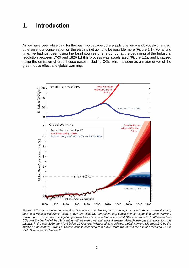
As we have been observing for the past two decades, the supply of energy is obviously changed, otherwise, our conservation on the earth is not going to be possible more (Figure 1.1). For a long time, we had just been using the fossil sources of energy, but at the beginning of the Industrial revolution between 1760 and 1820 [1] this process was accelerated (Figure 1.2), and it caused rising the emission of greenhouse gases including CO2, which is seen as a major driver of the greenhouse effect and global warming.
Figure 1.1 Two possible future scenarios: One in which no climate policies are implemented (red), and one with strong actions to mitigate emissions (blue). Shown are fossil CO2 emissions (top panel) and corresponding global warming (bottom panel). The shown mitigation pathway limits fossil and land-use related CO2 emissions to 1,000 billion tons CO2 over the first half of the 21st century with near-zero net emissions thereafter. Greenhouse gas emissions from this pathway in the year 2050 are ~70% below 1990 levels. Without climate policies, global warming will cross 2°C by the middle of the century. Strong mitigation actions according to the blue route would limit the risk of exceeding 2°C to 25%. Source and ©: Nature [2].

3
Figure 1.2 Growth of global CO2 emissions from fossil fuels in Gt CO2 per year (1750-2006), [7,3].
For Example, in order to keep climate change below 2ºC, the European Council reconfirmed in February 2011 the EU objective of reducing greenhouse gas emissions by 80-95% by 2050 compared to 1990, in the context of necessary reductions according to the Intergovernmental Panel on Climate Change by developed countries as a group 3. This is in line with the position endorsed by world leaders in the Copenhagen and the Cancun Agreements. These agreements include the commitment to deliver long-term low carbon development strategies [4]. Figure 1.3 illustrates the pathway towards an 80% reduction by 2050, shown in 5-year steps. The upper "reference" projection shows how domestic greenhouse gas emissions would develop under current policies.
Figure 1.3 EU GHG emissions towards an 80% domestic reduction (100% =1990), [4].

4
The best way to control and reverse these process is a transition to renewable and clean energy sources, such as wind power and photovoltaic cells. But this strategy will lead to some challenges that the most important ones are going to be reported here:
In contrast to conventional power plants, renewable energies are known as fluctuating and intermittent energy sources and they depend on atmospheric conditions, day and night or season etc. Consequently, there is a need to store energy (electricity) when it is available, to provide and apply it immediately on demand and to transport it cheaply and efficiently for other customers with different requirement.
Also, if it is going to replace renewable energy with 40% of required fossil energy by 2050 according to Figure 1.3, one might anticipate about converting renewable energy to transportable fuels for mobile applications that be able to use by combustion engines.
Scientists and researchers have been looking for a way to overcome these challenges and they have introduced a number of methods, which are based on mechanical or chemical processes [5], such as:
1. Mechanical electrical storage systems (Compressed air, Flywheel energy storage, Hydroelectric pumped)
2. Flow battery 3. Thermal storage system 4. Thermochemical (called solar fuel also and different fuels can be generated by solar
systems such as hydrogen, hydrocarbons and heat pipes). 5. Hydrogen system 6. Power to gas system
In the following will be explained some reasons caused power to gas systems have particularly been considered today in the energy market.
1.1. Motivation
The chemical storages by means of so-called chemical energy carriers and in particular of synthetic natural gas (SNG) are capable to overcome the mentioned challenges (in the previous chapter), due to transition from conventional energy system to renewable energy systems. Hence, available renewable energy can be consumed to electrolyze water to hydrogen and oxygen. The produced hydrogen can then be synthesized with carbon dioxide separated for instance from off-gas of fossil power plants (Figure 1.4), cement industry, biomass conversion or from the atmosphere to methane (Table 1.1) [6,8]. This methane can easily be stored in the gas reservoirs, or transported via the gas grid and consumed as power resources or even feed for petrochemical plants, using already existing infrastructure (gas grid). As shown in figure (1.4), the power to gas plants has been creating a closed loop between electricity and natural gas networks. Where, the balance between these networks can be the most important role of power to gas plants in the future, while the infrastructure of this two networks have completely been structured before.
Table 1.1 Properties of different industrial large scale carbon sources [6,8].

5
Figure 1.4 Basic concept of a renewable power to methane plant (Wind/Solar-to-SNG) with concentrated CO2 from a tank, integrated into power and gas grid. Optionally, Surplus heat from methanation can be used in an ORC-CHP-plant to generate power [7].
1.2. Chapters overview
This thesis consists of six chapter. The first chapter describes the reasons, which justify the application of power-to-gas systems and cause the research groups in energy section expenditure time to develop its concepts. shortly there are going to be expressed the place and the role of Power to Gas technology in the future of energy industry. Chapter 2 is organized in a way, that readers can easily catch theoretical subjects about methanation reactions such as their fundamentals, concepts (history of more than one-century development) and catalysts. According to the title of thesis, methanation of CO2 and H2 is supposed to be the axis of subjects in this article but due to a clear connection between CO and CO2 methanation especially in methanation concepts and catalysts, CO methanation is advantageously considered along with the second chapter, also. Chapter 3 is dedicated to the power-to-gas demonstration projects that particularly are operational or planned at this moment. Pilot plants are considered during the investigations also. despite, the subject of this article is limited to the CO2 methanation within the power to gas plants, the other power to gas projects including hydrogen-methane, and hydrogen plants are briefly mentioned in the separated parts. Chapter 4 contains a comprehensive discussion of simulation and modeling and its applications in the power to gas processes. Also in this chapter, a basic model is developed for methanation reactors using Excel. This model is able to calculate the working state and the equilibrium state of methanation reactors and compare them with presenting the Distance to Equilibrium State (DES) parameter. Chapter 5 is concentrated on the research topic and trying to introduce the investigations and research groups based on the subjects belong to the power to gas subcategories. Chapter 6 is presented a summary of discussed subjects. Especially, as a conclusion of this chapter is tried to illustrate for new researchers a comprehensive overview about the CO2 methanation concepts within the power to gas technology to accompany and facilitate more comfortable new developments in this field.

6
Chapter 2
Theoretical Background
7
2. Theoretical Background
2.1. Methanation fundamentals
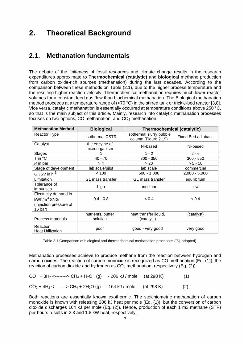
The debate of the finiteness of fossil resources and climate change results in the research expenditures approximate to Thermochemical (catalytic) and biological methane production from carbon oxide-rich sources (methanation) during the last decades. According to the comparison between these methods on Table (2.1), due to the higher process temperature and the resulting higher reaction velocity, Thermochemical methanation requires much lower reactor volumes for a constant feed gas flow than biochemical methanation. The Biological methanation method proceeds at a temperature range of (<70 °C) in the stirred tank or trickle-bed reactor [3,8]. Vice versa, catalytic methanation is essentially occurred at temperature conditions above 250 °C, so that is the main subject of this article. Mainly, research into catalytic methanation processes focuses on two options, CO methanation, and CO2 methanation.
Methanation Method Biological Thermochemical (catalytic) Reactor Type
Isothermal CSTR Isothermal slurry bubble
column (Figure 2.19) Fixed Bed adiabatic
Catalyst the enzyme of microorganism
Ni-based Ni-based
Stages 1 1 - 2 2 - 6 T in °C 40 - 70 300 - 350 300 - 550 P in bar > 4 > 20 > 5 - 10 Stage of development lab scale/pilot lab scale commercial
GHSV in h-1 < 100 500 - 1,000 2,000 - 5,000
Limitation GL mass transfer GL mass transfer equilibrium Tolerance of impurities
high medium low
Electricity demand in
kWh/m3 SNG
(injection pressure of 16 bar)
0.4 - 0.8 < 0.4 < 0.4
Process materials
nutrients, buffer solution
heat transfer liquid, (catalyst)
(catalyst)
Reaction Heat Utilization
poor good - very good
very good
Table 2.1 Comparison of biological and thermochemical methanation processes ([8], adapted).
Methanation processes achieve to produce methane from the reaction between hydrogen and carbon oxides. The reaction of carbon monoxide is recognized as CO methanation (Eq. (1)), the reaction of carbon dioxide and hydrogen as CO2 methanation, respectively (Eq. (2)). CO + 3H2 <--------> CH4 + H2O (g) - 206 kJ / mole (at 298 K) (1) CO2 + 4H2 <--------> CH4 + 2H2O (g) -164 kJ / mole (at 298 K) (2) Both reactions are essentially known exothermic. The stoichiometric methanation of carbon monoxide is known with releasing 206 kJ heat per mole (Eq. (1)), but the conversion of carbon dioxide discharges 164 kJ per mole (Eq. (2)). Hence, production of each 1 m3 methane (STP) per hours results in 2.3 and 1.8 kW heat, respectively.

8
The hydrogen and carbon monoxide are fed in CO methanation reaction (Eq. (1)) as educt gases for the catalytic production of methane and water, which they are normally supplied by coal or biomass gasification at synthetic fuel production plants (Figure 2.1) [9].
Figure 2.1 Exemplary biomass/coal-to-SNG plant setup with CO methanation, [10].
Educt gases in CO2 methanation plants are carbon dioxide and hydrogen (Eq. (2)). As shown in figure (2.2), CO2 methanation unlocks the doors to the chemical storage of electrical energy (Power to Gas), when an electrolysis supplies hydrogen into the feed stream [11].
Figure 2.2 Exemplary PtG plant setup with CO2 methanation [10].
9
In power to gas plants the central role is played by the CO2 methanation, so consequently this article is dedicated to cover all aspects of CO2 methanation, but CO methanation is slightly considered also because, it is one of the side reactions in CO2 methanation reactors, therefore it effectively is capable to change the efficiency of reactor and plant. On the other hand, CO2 methanation (Eq. (2)) is a linear combination of CO methanation (Eq. (1)) and reverse water-gas shift reaction (Eq. (3)), which always attends the CO methanation reaction using nickel catalysts in practical operation (section 2.1.2.2). However, conversion of CO2 can be inhibited, if the CO concentration overpasses a certain threshold [12]. CO2 + H2 <---------> CO + H2O (g) 41 kJ / mole (at 298 K) (3)
2.1.1. Equilibrium
The chemical equilibrium will occur, when the state properties of the system (temperature, pressure, concentration, etc...) as a function of time are constant. The practically equilibrium state is impossible to fulfill. In other words, a system requires infinite time to reach an equilibrium state, hence researchers try to define a particular kinetics equation for every reaction, by that they can predict the state of the system and consequently it's properties such as composition as a function of time. The Second Law of Thermodynamics (2nd Law) has been explained in different ways. Here two practical declarations are presented:
Heat will always flow from the hot to the cold side, never the other way. Chemical reactions always proceed towards an equilibrium state (with respect to
temperature, pressure, and composition).
These considerations impose some limits to processes comparable to balances [13]. The second expression of the 2nd Law above can answer this question: how can the chemical equilibrium point be estimated for mixtures of species with the chemical
reaction?
If, without derivation of the principle, we introduce the so-called Gibbs free enthalpy (G): G = H - T.S (4) All involved quantities are properties of the state. The formal expression of the second law can now be made using the Gibbs free enthalpy: G -------> Min (5) The 2nd Law in this form is also called the principle of Minimization of Gibbs Free Enthalpy and It means that:
o Equilibrium is fulfilled if any further change in composition due to chemical reactions would lead to an increase of the intensive Gibbs free enthalpy (typically the molar quantity is used to work with) [13].
A chemical reaction is generally defined by:
10
∑ vi. Ai = 0 (6)
Where Ai are all species taking part in the reaction and vi are their stoichiometric coefficients (vi are negative for reactants and positive for products). The equilibrium constant for partial pressures is defined as a dimensionless parameter of the partial pressures relative to standard pressure as follows:
Kp = π (pi*/p0)
vi (7)
The superscript asterisk in (7) indicates that the partial pressures represent the equilibrium state. In the case of ideal gases, the equilibrium constant is a function of temperature only and can straightforward be calculated from standard pressure Gibbs free enthalpy of reaction:
Ln (Kp (T)) = - ∆G°R (T) / R.T (8)
∆G°R (T) is the Gibbs free enthalpy of reaction at standard pressure (1 bar) [13].
2.1.1.1. Chemical equilibrium of the Sabatier reaction As discussed above, one way to determine the equilibrium is Gibbs free energy where Kp, the equilibrium constant, is a substantial variable. The equations (9) and (10) below are related to Kp for the Sabatier reaction (Eq. (2)) that are resulted from equations (7) and (8) respectively [14,15]: Kp = (X2
H2O * XCH4) (XCO2 * X4H2)
-1(p/p0)-2 (9)
Kp = Exp (- ∆GoT / R. T) (10)
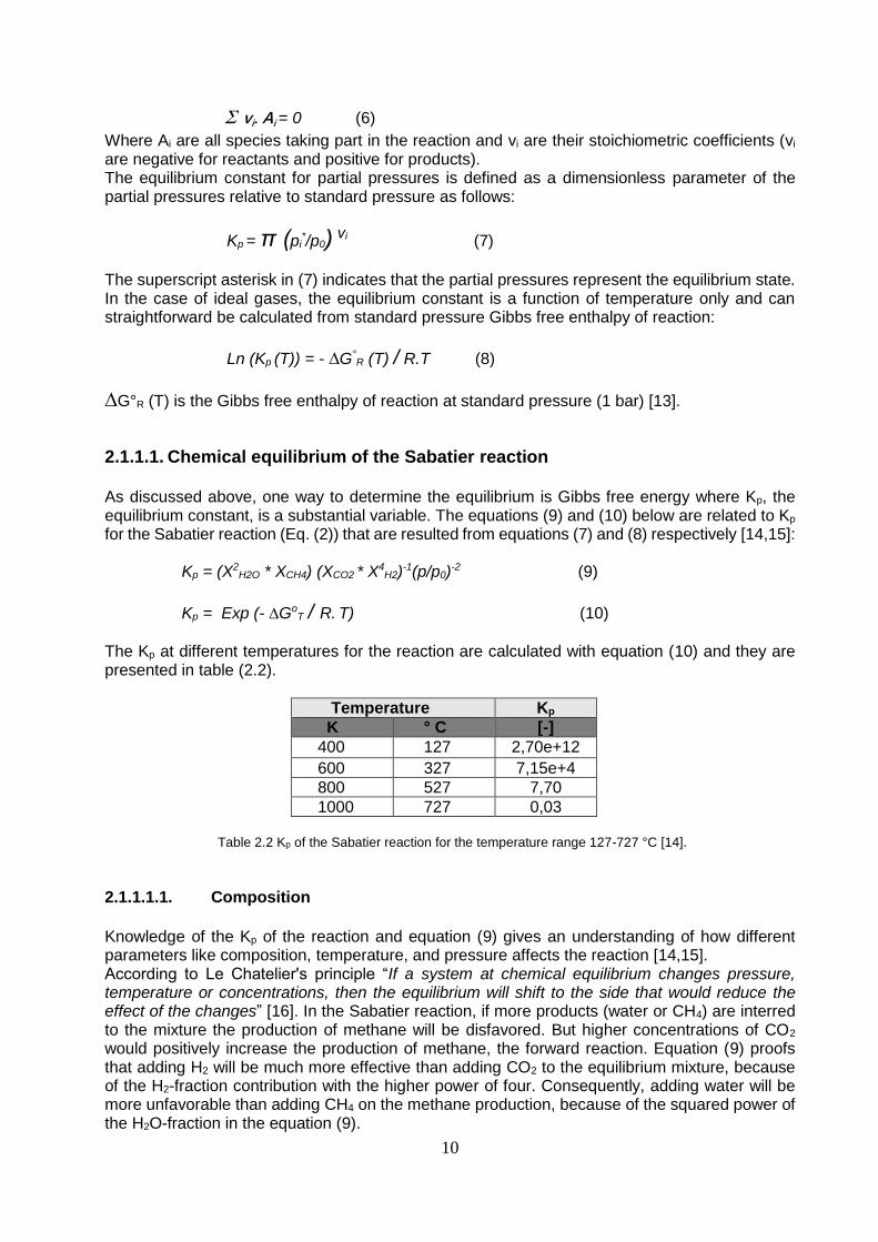
The Kp at different temperatures for the reaction are calculated with equation (10) and they are presented in table (2.2).
Temperature Kp
K ° C [-]
400 127 2,70e+12
600 327 7,15e+4
800 527 7,70
1000 727 0,03
Table 2.2 Kp of the Sabatier reaction for the temperature range 127-727 °C [14].
2.1.1.1.1. Composition
Knowledge of the Kp of the reaction and equation (9) gives an understanding of how different parameters like composition, temperature, and pressure affects the reaction [14,15]. According to Le Chatelier's principle “If a system at chemical equilibrium changes pressure, temperature or concentrations, then the equilibrium will shift to the side that would reduce the effect of the changes” [16]. In the Sabatier reaction, if more products (water or CH4) are interred to the mixture the production of methane will be disfavored. But higher concentrations of CO2 would positively increase the production of methane, the forward reaction. Equation (9) proofs that adding H2 will be much more effective than adding CO2 to the equilibrium mixture, because of the H2-fraction contribution with the higher power of four. Consequently, adding water will be more unfavorable than adding CH4 on the methane production, because of the squared power of the H2O-fraction in the equation (9).

11
2.1.1.1.2. Temperature
As shown in figure (2.3), high temperatures, by contrast, decreases the formation of methane, because Kp has an inverse proportion to temperature. This understanding is also proved by Equation (10) and Table (2.2).
Figure 2.3 Thermodynamic equilibrium of the Sabatier reaction at different temperatures and pressures [8].
2.1.1.1.3. Pressure
In thermodynamic equilibrium, high pressures favor the production of methane, respectively conversion of hydrogen (Figure 2.3), because the number of moles of the reactants is higher than the number of moles in the products. Therefore, increasing the pressure will move the equilibrium to the products side. This can also be seen in equation (9) where the (p/p0)-2 factor explains the pressure dependency behavior of Kp [14,15].
2.1.1.2. Comparison of the equilibrium conditions between CO and CO2-Methanation
As discussed before, the equilibrium of both CO and CO2 methanation reaction, (Eq. (1)) and (Eq. (2)) depend on composition, temperature, and pressure (Kp is also a function of state).
Figure 2.4 Effects of pressure and temperature on CO conversion [17].

12
The commercial process modeling software, such as Aspen Plus and Chemcad are easily able to model these reactions in equilibrium states and compare the influences of temperature, pressure, and composition of reactant species or even composition of non-reaction species in detailed graphs and charts [17]. The influence of pressure and temperature on the conversion of CO and CO2 methanation at the chemical equilibrium states are shown in figure (2.4) and figure (2.5) respectively, by way of example. Since methanation reactions are exothermal (section 2.1.1.1.2), temperature enhancement in methanation reactor decreases the conversion of hydrocarbons in both CO and CO2 reactions. This prediction is also appeared in figures (2.4) and (2.5), in addition, according to these figures CO conversion shows a larger drop in comparison with CO2 conversion because CO methanation releases more heat (206 kJ/mole) than CO2 methanation (164 kJ/mole). Vice versa, the pressure increase has a positive effect on the conversion of carbon oxides (Figures (2.4) and (2.5)). However, the same differences between the stoichiometric factor or reacting substances, for equation (1) {4 molesin - 2 molesout = 2 moles} and for equation (2) {5 molesin – 3 molesout = 2 moles}, that taking part in both reactions caused similar behavior against changing of pressure (concentration) within reactors.
Figure 2.5 Effects of pressure and temperature on CO2 conversion [17].
2.1.2. Mechanism
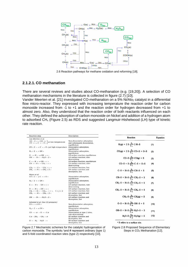
Developing and improving methanation technology would be impossible if researchers have not considered the mechanism of reactions. This subject seems to be particularly essential for developing the Kinetic of reactions and catalysts and at the same time very controversial. The researchers in this field try to discover the paths that, the reactants should go through to form the products. For example, in figure (2.6) is demonstrated reaction pathways for methane oxidation and reforming [18]. In fact, scientists try to define, choose, investigate and develop these pathways with respect to particular specifications for each reaction. After this progress, they can estimate the Rate-Determining Step (RDS) through each reaction to develop a reliable kinetic. The mechanism of a reaction tightly depends on the catalyst using the reaction. Hence, the most common catalysts in the methanation processes are based on nickel (section 2.3), here the mechanism of CO and CO2 methanation on nickel-basis catalysts will be presented below. Although CO-methanation is not supposed to investigate in the current article, in the next section it is briefly considered.
13
2.6 Reaction pathways for methane oxidation and reforming [18].
2.1.2.1. CO methanation There are several reviews and studies about CO-methanation (e.g. [19,20]). A selection of CO methanation mechanisms in the literature is collected in figure (2.7) [10]. Vander Meerten et al. [21] investigated CO-methanation on a 5% Ni/Alo2 catalyst in a differential flow micro-reactor. They expressed with increasing temperature the reaction order for carbon monoxide increased from -1 to +1 and the reaction order for hydrogen decreased from +1 to almost zero. Also, they understood that the reaction order of both reactants influenced on each other. They defined the adsorption of carbon monoxide on Nickel and addition of a hydrogen atom to adsorbed CHx (Figure 2.5) as RDS and suggested Langmuir-Hishelwood (LH) type of kinetic rate reaction.
Figure 2.7 Mechanistic schemes for the catalytic hydrogenation of Figure 2.8 Proposed Sequence of Elementary carbon monoxide. The symbols ⁄ and # represent ordinary (type 1) Steps in CO2 Methanation [12]. and 5-fold coordinated reaction sites (type 2) respectively [10].

14
Hayes et al. [22] used chemical and physical techniques to investigate the nickel-catalysts reactions. They introduced the NiΞC—H complex as RDS. Also, they introduced the best possible rate reaction using power law method. Sehested et al. [23] investigated CO-methanation at low CO concentration and the H2-pressure a little higher than the atmosphere. The dissociation of CO on the nickel surface was chosen as RDS and the proposed kinetic by them is a first-order expression.
2.1.2.2. CO2 methanation Weatherbee and Bartholomew published (1982) a comprehensively report [12] regarding the investigation of CO2-hydrogenation, comprising:
Set up an experimental facility based on CO2-methanation. Collecting operational data during the experimentation phase. Developing a series of reaction pathways and estimation the RDS steps. Developing a kinetic-based on LH method, which can fit the experimental data.
They run the experiments with 3% Ni/SiO2 catalyst at temperatures between 227 and 327 °C, total pressures between 140 and 175 kPa, and space velocities between 30000 and 90000 h-1 with a maximum CO2 conversion of 10% in an isothermal, one-pass differential reactor. H2 and CO partial pressures varied between 2% and 10% and 0.2% and 2% of total pressure, respectively. They suggested the mechanism (Figure 2.8), with CO2 being adsorbed dissociative on Ni, thus forming adsorbed CO and O species. After analyzing the results, they found a simple power law since the rate could not be fitted to the experimental data. Instead, an LH rate equation (Figure 4.2) was used for data fitting. Further conversion of adsorbed CO into CH4 was expected as in the case of CO hydrogenation (Eq. (2) from figure 2.8). Based on this, it was tried to fit the experimental data with LH rate equations. The assumption of the dissociation of adsorbed CO being the RDS was the only one that resulted in physically meaningful rate and adsorption equilibrium constants. This is also supported by the observation of comparable specific reaction rates in CO2 and CO methanation on Ni/SiO2. The mentioned RDS is applicable at moderate temperatures between 252 and 302 °C. At higher temperatures (>302 °C), hydrogenation of carbon (Eq. (5) from figure 2.8) might be rate-controlling. Also, Stefan Rönsch, et al. [10] explained very well the CO2 methanation reaction mechanism based on some useful studies, (e.g. [24,25,20,26-28]) that could be useful on this subject for more details.
2.2. Methanation concepts
2.2.1. History
Sabatier and Senderens in 1902 were the discoverers of the methanation processes [29]. These reactions have been investigated and developed by researchers during more than a century (Figure 2.9). During this period, different circumstances had been motivated researchers to apply these processes in the industry (e.g. Oil crisis, Global warming). Historically, the CO-methanation could firstly take part in the industry. The most important applications of the CO-methanation have included cleaning the carbon monoxide from syngases such as ammonia production Plants and proton-exchange membrane fuel cells. The energy crisis in the late 1970s motivated the researcher to use CO methanation for the production of SNG. They were going to produce natural
15
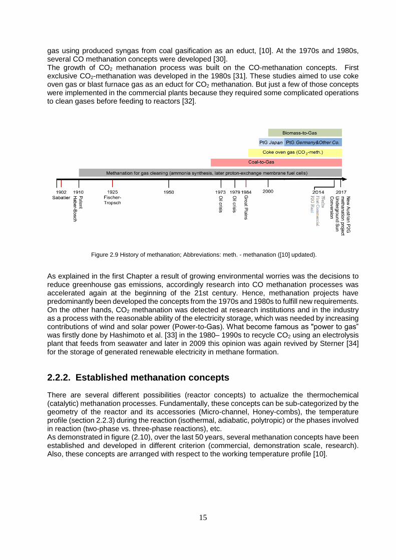
gas using produced syngas from coal gasification as an educt, [10]. At the 1970s and 1980s, several CO methanation concepts were developed [30]. The growth of CO2 methanation process was built on the CO-methanation concepts. First exclusive CO2-methanation was developed in the 1980s [31]. These studies aimed to use coke oven gas or blast furnace gas as an educt for CO2 methanation. But just a few of those concepts were implemented in the commercial plants because they required some complicated operations to clean gases before feeding to reactors [32].
Figure 2.9 History of methanation; Abbreviations: meth. - methanation ([10] updated).
As explained in the first Chapter a result of growing environmental worries was the decisions to reduce greenhouse gas emissions, accordingly research into CO methanation processes was accelerated again at the beginning of the 21st century. Hence, methanation projects have predominantly been developed the concepts from the 1970s and 1980s to fulfill new requirements. On the other hands, CO2 methanation was detected at research institutions and in the industry as a process with the reasonable ability of the electricity storage, which was needed by increasing contributions of wind and solar power (Power-to-Gas). What become famous as "power to gas” was firstly done by Hashimoto et al. [33] in the 1980– 1990s to recycle CO2 using an electrolysis plant that feeds from seawater and later in 2009 this opinion was again revived by Sterner [34] for the storage of generated renewable electricity in methane formation.
2.2.2. Established methanation concepts
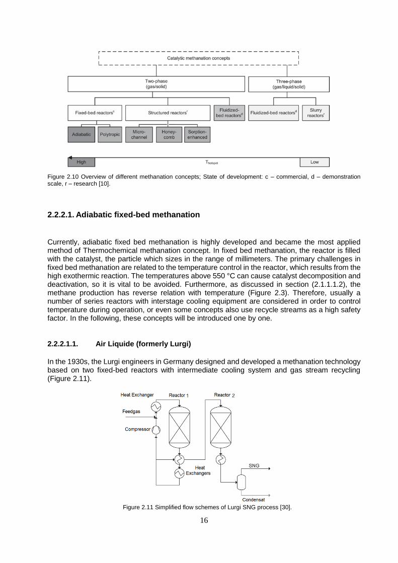
There are several different possibilities (reactor concepts) to actualize the thermochemical (catalytic) methanation processes. Fundamentally, these concepts can be sub-categorized by the geometry of the reactor and its accessories (Micro-channel, Honey-combs), the temperature profile (section 2.2.3) during the reaction (isothermal, adiabatic, polytropic) or the phases involved in reaction (two-phase vs. three-phase reactions), etc. As demonstrated in figure (2.10), over the last 50 years, several methanation concepts have been established and developed in different criterion (commercial, demonstration scale, research). Also, these concepts are arranged with respect to the working temperature profile [10].
16
Figure 2.10 Overview of different methanation concepts; State of development: c – commercial, d – demonstration scale, r – research [10].
2.2.2.1. Adiabatic fixed-bed methanation
Currently, adiabatic fixed bed methanation is highly developed and became the most applied method of Thermochemical methanation concept. In fixed bed methanation, the reactor is filled with the catalyst, the particle which sizes in the range of millimeters. The primary challenges in fixed bed methanation are related to the temperature control in the reactor, which results from the high exothermic reaction. The temperatures above 550 °C can cause catalyst decomposition and deactivation, so it is vital to be avoided. Furthermore, as discussed in section (2.1.1.1.2), the methane production has reverse relation with temperature (Figure 2.3). Therefore, usually a number of series reactors with interstage cooling equipment are considered in order to control temperature during operation, or even some concepts also use recycle streams as a high safety factor. In the following, these concepts will be introduced one by one.
2.2.2.1.1. Air Liquide (formerly Lurgi)
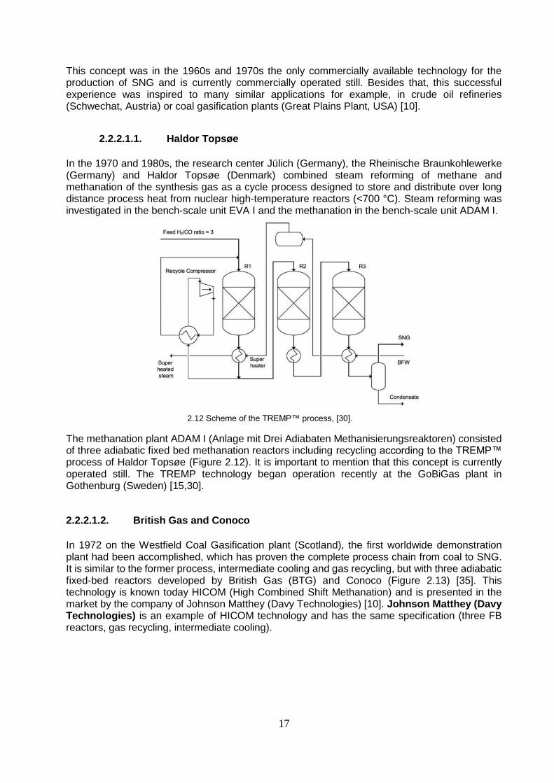
In the 1930s, the Lurgi engineers in Germany designed and developed a methanation technology based on two fixed-bed reactors with intermediate cooling system and gas stream recycling (Figure 2.11).
Figure 2.11 Simplified flow schemes of Lurgi SNG process [30].
17
This concept was in the 1960s and 1970s the only commercially available technology for the production of SNG and is currently commercially operated still. Besides that, this successful experience was inspired to many similar applications for example, in crude oil refineries (Schwechat, Austria) or coal gasification plants (Great Plains Plant, USA) [10].
2.2.2.1.1. Haldor Topsøe
In the 1970 and 1980s, the research center Jülich (Germany), the Rheinische Braunkohlewerke (Germany) and Haldor Topsøe (Denmark) combined steam reforming of methane and methanation of the synthesis gas as a cycle process designed to store and distribute over long distance process heat from nuclear high-temperature reactors (<700 °C). Steam reforming was investigated in the bench-scale unit EVA I and the methanation in the bench-scale unit ADAM I.
2.12 Scheme of the TREMP™ process, [30].
The methanation plant ADAM I (Anlage mit Drei Adiabaten Methanisierungsreaktoren) consisted of three adiabatic fixed bed methanation reactors including recycling according to the TREMP™ process of Haldor Topsøe (Figure 2.12). It is important to mention that this concept is currently operated still. The TREMP technology began operation recently at the GoBiGas plant in Gothenburg (Sweden) [15,30].
2.2.2.1.2. British Gas and Conoco
In 1972 on the Westfield Coal Gasification plant (Scotland), the first worldwide demonstration plant had been accomplished, which has proven the complete process chain from coal to SNG. It is similar to the former process, intermediate cooling and gas recycling, but with three adiabatic fixed-bed reactors developed by British Gas (BTG) and Conoco (Figure 2.13) [35]. This technology is known today HICOM (High Combined Shift Methanation) and is presented in the market by the company of Johnson Matthey (Davy Technologies) [10]. Johnson Matthey (Davy Technologies) is an example of HICOM technology and has the same specification (three FB reactors, gas recycling, intermediate cooling).
18
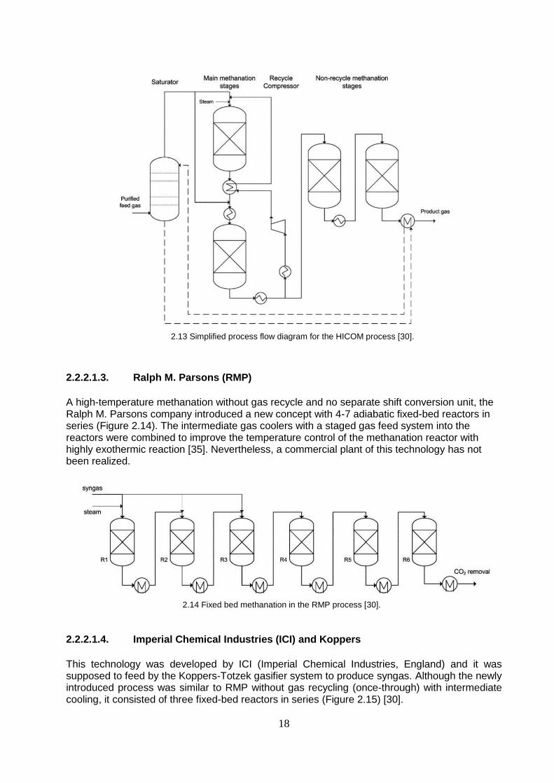
2.13 Simplified process flow diagram for the HICOM process [30].
2.2.2.1.3. Ralph M. Parsons (RMP)
A high-temperature methanation without gas recycle and no separate shift conversion unit, the Ralph M. Parsons company introduced a new concept with 4-7 adiabatic fixed-bed reactors in series (Figure 2.14). The intermediate gas coolers with a staged gas feed system into the reactors were combined to improve the temperature control of the methanation reactor with highly exothermic reaction [35]. Nevertheless, a commercial plant of this technology has not been realized.
2.14 Fixed bed methanation in the RMP process [30].
2.2.2.1.4. Imperial Chemical Industries (ICI) and Koppers
This technology was developed by ICI (Imperial Chemical Industries, England) and it was supposed to feed by the Koppers-Totzek gasifier system to produce syngas. Although the newly introduced process was similar to RMP without gas recycling (once-through) with intermediate cooling, it consisted of three fixed-bed reactors in series (Figure 2.15) [30].
19
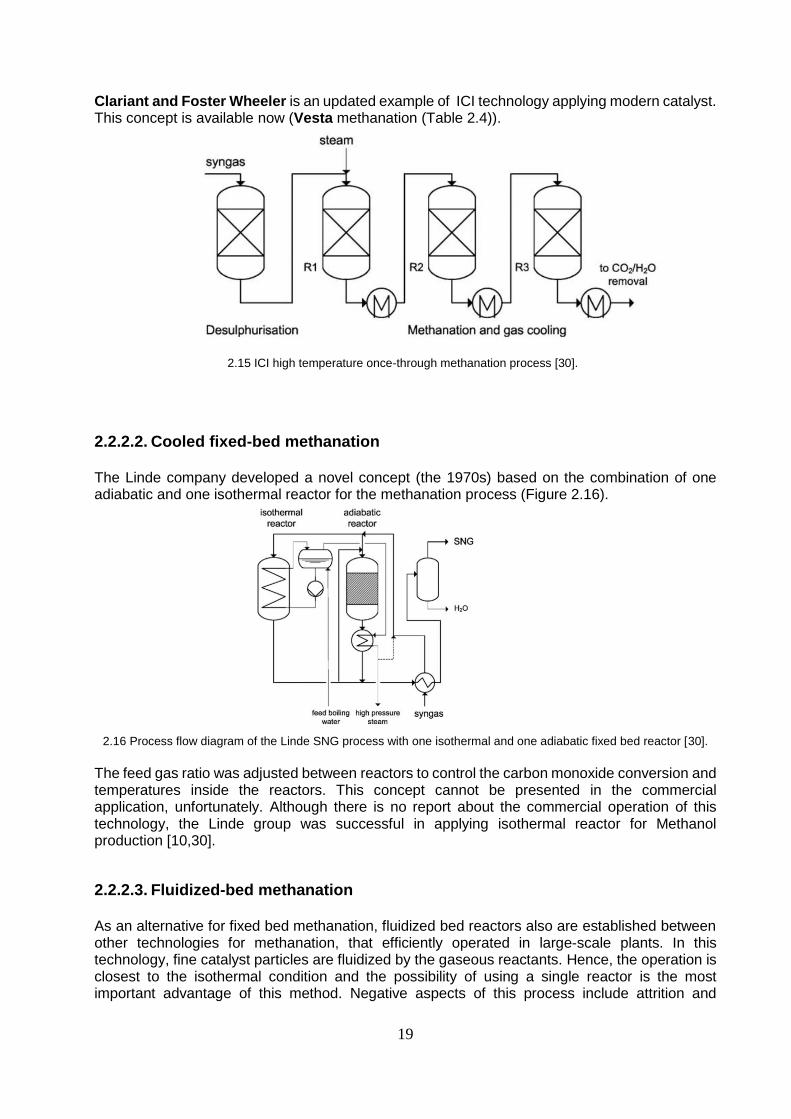
Clariant and Foster Wheeler is an updated example of ICI technology applying modern catalyst. This concept is available now (Vesta methanation (Table 2.4)).
2.15 ICI high temperature once-through methanation process [30].
2.2.2.2. Cooled fixed-bed methanation The Linde company developed a novel concept (the 1970s) based on the combination of one adiabatic and one isothermal reactor for the methanation process (Figure 2.16).
2.16 Process flow diagram of the Linde SNG process with one isothermal and one adiabatic fixed bed reactor [30].
The feed gas ratio was adjusted between reactors to control the carbon monoxide conversion and temperatures inside the reactors. This concept cannot be presented in the commercial application, unfortunately. Although there is no report about the commercial operation of this technology, the Linde group was successful in applying isothermal reactor for Methanol production [10,30].
2.2.2.3. Fluidized-bed methanation As an alternative for fixed bed methanation, fluidized bed reactors also are established between other technologies for methanation, that efficiently operated in large-scale plants. In this technology, fine catalyst particles are fluidized by the gaseous reactants. Hence, the operation is closest to the isothermal condition and the possibility of using a single reactor is the most important advantage of this method. Negative aspects of this process include attrition and

20
breakage of the catalyst due to the high physical stresses between catalyst particles and reactor walls. Incomplete conversion because of bubbling is also an issue [8].
2.2.2.3.1. Bituminous Coal Research Inc.
Due to the sophisticated process control, fluidized-bed methanation processes were primarily investigated by research institutions (e.g. the Synthase process of the Bureau of Mines’s Fuel Technology Division). One of the first fluidized-bed methanation processes developed by industry was the Bi-Gas-Process of Bituminous Coal Research Inc. (Figure 2.17). The reactor contained two internal heat exchangers in the bed. The development started in 1963 and the reactor was tested at the laboratory for several thousand hours [30].
2.17 Bi-gas process flow diagram, adapted from [30].
2.2.2.3.2. Thyssengas
Another fluidized-bed reactor concept with internal heat exchanger was developed by Thyssengas GmbH (Figure 2.18), Didier Engineering GmbH, and the DVGW-Forschungsstelle in Karlsruhe (Germany). A first test plant of this COMFLUX process was constructed in 1977, and a pilot plant was commercially operated at the Ruhrchemie plant site in Oberhausen (Germany) [10,30].
2.18 Thyssengas process flow diagram [30].

21
The Comflux process was developed by Engler-Bunte-Institut in conjunction with Thyssengas GmbH from which a demonstration plant was built to produce 2,000 m3/h SNG. In 2009, the Comflux process was used to produce SNG from solid biomass in a 1 MW plant in Güssing, Austria [8].
2.2.2.4. Three-phase methanation
In three-phase methanation (Figure 2.19), a solid catalyst (powder < 100 µm) is fluidized in a temperature stable inert liquid (mineral oil, due to its high heat capacity (Cp)) such as dibenzyltoluene. The first three-phase methanation concept was developed by Chem Systems Inc., from 1975 – 1981. The concept was based on a single three-phase fluidized bed reactor operated up to 70 bar.
Figure 2.19 Schematic diagram of the three-phase reactor concept [8].
Currently, the three-phase methanation in a slurry bubble column reactor is under verifying at laboratory scale at the Engler-Bunte-Institut, Germany and at the Institute of Coal Chemistry, China. Good heat rejection of the reaction is a remarkable advantage for this method, as it allows for good heat control of the reaction. This is particularly important in the PtG process since the high heat capacity of the liquid phase makes it easier for the methanation process to handle the fluctuations/downtime. Moreover, the catalyst can be replaced during operation. However, a major disadvantage of the three-phase methanation is the liquid side mass transfer limitation, which reduces the effective reaction rate. In the same way with the CO methanation, the recent CO2 methanation process innovations (last decades) are based on methanation concepts from the 1970s and 1980s. Nevertheless, some vital adaptations regarding e.g. temperature controlling of the reactor and dynamic operation
behavior had to be exerted [8].
2.2.2.5. Market availability As explained, methanation research and its developed concepts look back on a history of more than 100 years, nevertheless, not all concepts are commercially available now. Here is given an overview of commercially available technologies for the CO2 and CO-methanation in Tables (2.3) and (2.4) respectively. The technologies listed in (Table 2.4) can be practically employed at CO2 methanation plants [10].
22
Supplier Concept Technology name
Outotec
Staged fixed-bed reactor with
intermediate cooling
Outotec methanation
Etogas
Fixed-bed reactor or plate reactor with
steam cooling
Etogas methanation
MAN One isothermal fixed-bed reactor with
molten salt cooling
MAN methanation
Table 2.3 CO2-Methanation technologies available on the market [10].
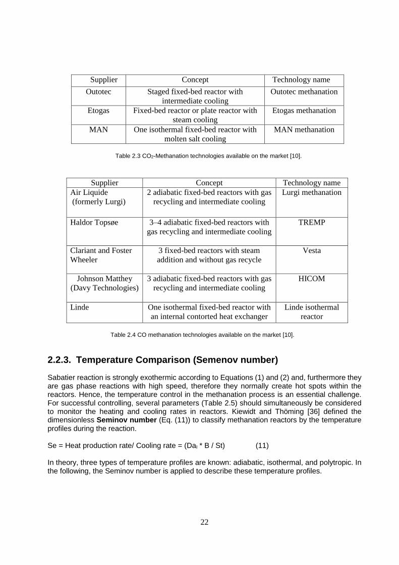
Supplier Concept Technology name
Air Liquide
(formerly Lurgi)
2 adiabatic fixed-bed reactors with gas
recycling and intermediate cooling
Lurgi methanation
Haldor Topsøe 3–4 adiabatic fixed-bed reactors with
gas recycling and intermediate cooling
TREMP
Clariant and Foster
Wheeler
3 fixed-bed reactors with steam
addition and without gas recycle
Vesta
Johnson Matthey
(Davy Technologies)
3 adiabatic fixed-bed reactors with gas
recycling and intermediate cooling
HICOM
Linde One isothermal fixed-bed reactor with
an internal contorted heat exchanger
Linde isothermal
reactor
Table 2.4 CO methanation technologies available on the market [10].
2.2.3. Temperature Comparison (Semenov number)
Sabatier reaction is strongly exothermic according to Equations (1) and (2) and, furthermore they are gas phase reactions with high speed, therefore they normally create hot spots within the reactors. Hence, the temperature control in the methanation process is an essential challenge. For successful controlling, several parameters (Table 2.5) should simultaneously be considered to monitor the heating and cooling rates in reactors. Kiewidt and Thöming [36] defined the dimensionless Seminov number (Eq. (11)) to classify methanation reactors by the temperature profiles during the reaction. Se = Heat production rate/ Cooling rate = (DaI * B / St) (11) In theory, three types of temperature profiles are known: adiabatic, isothermal, and polytropic. In the following, the Seminov number is applied to describe these temperature profiles.

23
Parameter Symbol Definition Interpretation/ratio
Arrhenius number γ Ea/(Ru T0 ) Activation energy/thermal energy Heat production potential B -∆HR,0 γ / (M0 cp,0T0 ) Heat production/thermal storage capacity
1st Damköhler number DaI M0η0 r0(V)
LR / G0 Reaction rate/convective transport rate
Stanton number St 4UW,0(eff)
LR / (G0 cp,0Dt) Cooling rate/convective transport rate
Reynolds number Re GK / (µ0 cF ) Convective momentum transport rate/viscous momentum transport rate
Semenov number Se DaIB / St Heat production rate/cooling rate
Table 2.5 Summary of dimensionless parameters used within Semenov number [36].
Adiabatic reactors (Se ---> ∞) Fixed bed reactors without heat exchanging and high rate of the produced heat due to the reaction, typically display adiabatic temperature profile with a distributed hot spot in the bed and high-temperature levels.
Isothermal reactors (Se ---> 0) When the cooling rate is extremely bigger than produced reaction heat, then the isothermal temperature profile will be indicated. Fluidized-bed reactors and three-phase reactors ideally are isothermal reactors.
Polytropic reactors (0 < Se < ∞) If the cooling rate and produced heat rate have been well-balanced during the reaction process, the polytropic temperature profile will be recorded. Cooled fixed-bed and structured reactors (e.g. microchannel, honeycomb) are the best examples of these reactors.
2.3. Catalysts, activation, and deactivation
The catalyst is the place where the reaction occurs, hence, its material and shape directly effect on the design and operation of the reactor and its up- and downstream equipment and they should be coordinated with catalyst specification (such as activation, deactivation, and selectivity). In the following, an overview of methanation catalysts and its specifications is presented.
2.3.1. Catalysts
2.3.1.1. Active compound Sabatier and Senderens introduced nickel as the catalyzer for the methanation reaction (Eqs. (1) and (2)) [29]. It is very interesting that after more than 100 years many metals have been identified as an active material for the methanation reaction, but still due to its activity, selectivity and price in comparison with other materials the researchers are suggesting nickel as the optimal option for commercial applications [37]. For example, Vannice et al. [38] considered activity and selectivity of (Ru, Fe, Ni, Co, Rh, Pd, Pt, Ir) and published the following order:

24
Activity: Ru > Fe > Ni > Co > Rh > Pd > Pt > Ir Selectivity: Pd > Pt > Ir > Ni > Rh > Co > Fe > Ru In terms of metals important for methanation, Mills and Steffgen [37] limited the candidates for the investigation to Ru, Ni, Co, Fe, and Mo.
Activity: Ru > Fe > Ni > Co > Mo Selectivity: Ni > Co > Fe > Ru
2.3.1.2. Support Beside the active metal also other parts of a catalyst such as support, promoter and the skill of their preparation and conditions of putting them together are very important for a catalyst to be formed that promises high selectivity and activity [37]. The active metals are normally dispersed on metal-oxide supports (e.g. Al2O3, SiO2, TiO2, ZrO2, CeO2), however, Al2O3 is more frequently applied than others [39]. Beside the supported catalysts, also unsupported catalysts such as Raney-Nickel [40] are known.
2.3.1.3. Promoters The promoters are the materials (e.g. MgO, La2O3, V2O3, CeO2, K), which based on its structures are able to create positive or negative effects on the performance of the catalyst in a particular reaction (e.g. methanation) [10]. For example, the addition of (MgO) to Ni/Al2O3 improves the interaction between nickel atoms and the neighboring cations and support of the MgNiO2 though the particle size of NiO is constant [41]. But potassium (K) decreases the formation of methane and increases the formation of heavy hydrocarbons on pure Ni (100) catalysts and Ni/Al2O3 with high nickel concentration [42].
2.3.2. Reduction and activation
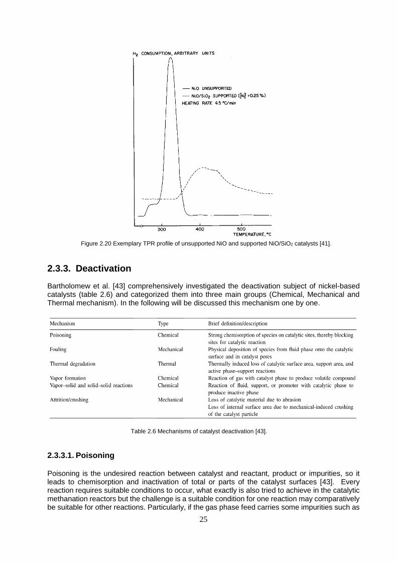
The nickel-based methanation catalysts, in contrast to many other catalytic processes (e.g. Fischer–Tropsch-Synthesis) do not need any separate activation step instead of reduction step. The reduction of nickel-based methanation catalysts requires floating in hydrogen at temperatures ranging from 300 to 600 °C [10]. The TPR (temperature-programmed reduction) measurements are applied monitoring the behavior of a catalyst under reductive conditions (increased temperature and hydrogen atmosphere) [41]. For example, TPR-profile of unsupported NiO and supported NiO/SiO2 catalysts are given in the Figure 2.20. The H2 consumption (Y-axis) is displayed as a function of temperature (X-axis). The considerable H2 consumption in the Figure 2.20 is indicating, where main reduction process takes place. Each mutation on the profile of H2 consumption can probably be related to a portion of the catalyst that is reduced at the specific temperature.
25
Figure 2.20 Exemplary TPR profile of unsupported NiO and supported NiO/SiO2 catalysts [41].
2.3.3. Deactivation
Bartholomew et al. [43] comprehensively investigated the deactivation subject of nickel-based catalysts (table 2.6) and categorized them into three main groups (Chemical, Mechanical and Thermal mechanism). In the following will be discussed this mechanism one by one.
Table 2.6 Mechanisms of catalyst deactivation [43].
2.3.3.1. Poisoning Poisoning is the undesired reaction between catalyst and reactant, product or impurities, so it leads to chemisorption and inactivation of total or parts of the catalyst surfaces [43]. Every reaction requires suitable conditions to occur, what exactly is also tried to achieve in the catalytic methanation reactors but the challenge is a suitable condition for one reaction may comparatively be suitable for other reactions. Particularly, if the gas phase feed carries some impurities such as

26
chlorine compounds, tars, particles, ammonia, sulfur compounds or alkalis. Nickel-based catalysts are prone to poisoning by sulfur compounds and must be considered by designers [44,45]. Rönsch S. [46,10] suggests Rectisol washing and adsorption with Zinc Oxide methods in methanation plants to protect them against catalyst poisoning by sulfur compositions. Hydrogen sulfide by the chemical reaction equation (Eq. (11)) converts nickel oxide to nickel sulfide that shows no activity for the methanation reaction [10]. H2S (g) + NiO (s) <------------> NiS (s) + H2O (g) (11)
2.3.3.2. Vapor–solid reactions Vapor-solid reaction (Eq. (12)) transfers applied solid nickel in the catalyst to gas phase nickel carbonyls in methanation plant at low temperature. Hence, it is an undesired reaction [47]. Then at startup and shutdown phases (dynamically or periodically operation) of the methanation plant, any contact between catalyst and carbon monoxide should be avoided because of this reaction [48,10]. Ni (s) + 4CO (g) <------------> Ni(CO)4 (g) (12)
2.3.3.3. Thermal degradation Sintering of the active catalyst causes loss of area and finally a reduction of catalyst efficiency. The temperature threshold of catalysts depends on their materials, but they must normally be kept away from temperatures above 500 °C. However, some catalysts for high-temperature between 600 and 700 °C are available on the market [49].
2.3.3.4. Fouling Against vapor-solid reaction, catalyst fouling means transferring some species from the gas phase onto catalyst material (solid phase) due to the chemical or physical transactions during operation. In methanation plants, especially the deposition of carbon and coke must be avoided. Carbon deposits are formed by the Boudouard reaction (Eq. (13)). Adding steam or rising the H2/CO-ratio is applied in methanation plants to prevent catalyst fouling by carbon or coke [10]. 2CO (g) <--------> CO2 (g) + C (s) (13)
2.3.3.5. Attrition The attrition of active catalyst material by abrasion is a troublous drawback reported often in operation of moving-bed, slurry-bed, or fluidized-bed reactors [79]. That is a harmful subject because it leads to financial expenditures for make-up catalysts and shouts down the operation. To prevent any failures on downstream equipment (e.g. pumps and compressors), it is vital to separate the abraded catalyst from the product gas [10].

27
2.3.3.6. Crushing The crushing of catalyst particles is also one of a number of different mechanical deactivation mechanisms. Crushing can be created either by sudden thermal stresses (due to very fast heating or cooling) or by mechanical stresses (due to pressure fluctuations in the reactor) [43]. Simultaneously, both situations can be accompanied by a startup and shutdown and as well as during operation of the plant. In addition, feed rate fluctuation by flexible methanation operation particularly of Power-To-Gas or poly-generation plants (an interdependent chain production plant), i.e. inconstancy of the syngas flow rate, may result in mechanical stressing crushing [10].

28
Chapter 3
Review of commercial plants and pilot projects

29
3. Review of commercial plants and pilot projects
This chapter is dedicated to the power-to-gas demonstration projects that particularly are operational or planned at this moment. According to the fact that power to gas is very young technology (Figure 3.3), prototype plant (Japan, 1996) and first commercial plant (Germany, 2013), during the investigation the pilot plants are considered also. Due to the subject of this article is limited to the catalytic CO2 methanation within the power to gas plants, here I focus on the investigation of Thermochemical (catalytic) methanation plants, nevertheless, the other power to gas projects including hydrogen-methane and hydrogen plants are briefly mentioned in separated parts. As a preliminary overview of the information that is going to be presented in the following, Figures 3.1 and 3.2 clearly illustrate the distribution of the projects between worldwide and European Union countries classified by type of process, respectively [50,51]. Germany is the leader of nations in applying and propounding PtG systems, due to an increasing requirement for chemical storage of produced electricity by fluctuating wind and solar energy sources. The projects in Germany mostly concentrate on CO2 catalytic methanation [50].
Figure 3.1 Existing PtG projects distributed by country and technology (2017) [50].
Figure 3.2 Power-to-gas (demonstration) projects in Europe, the symbols (□, ○, ӿ, ◊) represent the type of PtG plant
(Methane, Hydrogen, Hydrogen&Methane, Methanol) and the color of these symbols (Green, Gray, Red, Deep yellow, Light yellow) indicate the life cycle of project (Operational okt. 2016, Unknown okt. 2016, Finished okt. 2016, Planned feb. 2017, Nieuw planned.xlsx) respectively (2017) [51].
30
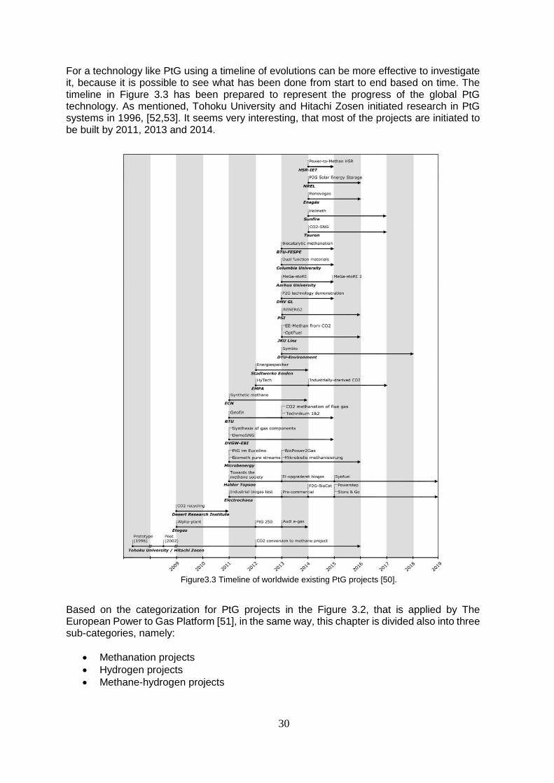
For a technology like PtG using a timeline of evolutions can be more effective to investigate it, because it is possible to see what has been done from start to end based on time. The timeline in Figure 3.3 has been prepared to represent the progress of the global PtG technology. As mentioned, Tohoku University and Hitachi Zosen initiated research in PtG systems in 1996, [52,53]. It seems very interesting, that most of the projects are initiated to be built by 2011, 2013 and 2014.
Figure3.3 Timeline of worldwide existing PtG projects [50].
Based on the categorization for PtG projects in the Figure 3.2, that is applied by The European Power to Gas Platform [51], in the same way, this chapter is divided also into three sub-categories, namely:
Methanation projects
Hydrogen projects
Methane-hydrogen projects
31
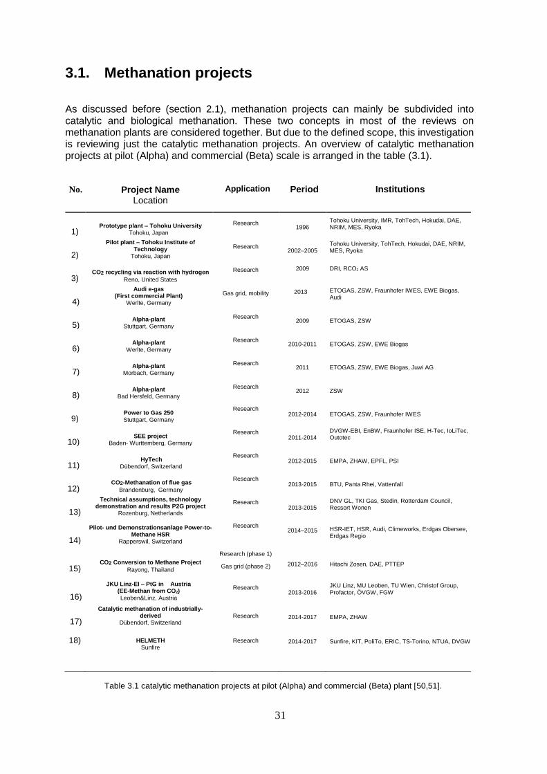
3.1. Methanation projects
As discussed before (section 2.1), methanation projects can mainly be subdivided into catalytic and biological methanation. These two concepts in most of the reviews on methanation plants are considered together. But due to the defined scope, this investigation is reviewing just the catalytic methanation projects. An overview of catalytic methanation projects at pilot (Alpha) and commercial (Beta) scale is arranged in the table (3.1).
No. Project Name
Location
Application Period Institutions
1) Prototype plant – Tohoku University
Tohoku, Japan
Research
1996 Tohoku University, IMR, TohTech, Hokudai, DAE, NRIM, MES, Ryoka
2)
Pilot plant – Tohoku Institute of Technology
Tohoku, Japan
Research
2002–2005 Tohoku University, TohTech, Hokudai, DAE, NRIM, MES, Ryoka
3) CO2 recycling via reaction with hydrogen
Reno, United States
Research 2009 DRI, RCO2 AS
4)
Audi e-gas (First commercial Plant)
Werlte, Germany
Gas grid, mobility 2013 ETOGAS, ZSW, Fraunhofer IWES, EWE Biogas,
Audi
5) Alpha-plant
Stuttgart, Germany
Research
2009 ETOGAS, ZSW
6) Alpha-plant
Werlte, Germany
Research
2010-2011 ETOGAS, ZSW, EWE Biogas
7) Alpha-plant
Morbach, Germany
Research
2011 ETOGAS, ZSW, EWE Biogas, Juwi AG
8) Alpha-plant
Bad Hersfeld, Germany
Research
2012 ZSW
9) Power to Gas 250 Stuttgart, Germany
Research 2012-2014 ETOGAS, ZSW, Fraunhofer IWES
10) SEE project
Baden- Wurttemberg, Germany
Research 2011-2014
DVGW-EBI, EnBW, Fraunhofer ISE, H-Tec, IoLiTec, Outotec
11) HyTech
Dübendorf, Switzerland
Research 2012-2015 EMPA, ZHAW, EPFL, PSI
12) CO2-Methanation of flue gas
Brandenburg, Germany
Research 2013-2015 BTU, Panta Rhei, Vattenfall
13)
Technical assumptions, technology demonstration and results P2G project
Rozenburg, Netherlands
Research 2013-2015
DNV GL, TKI Gas, Stedin, Rotterdam Council, Ressort Wonen
14)
Pilot- und Demonstrationsanlage Power-to- Methane HSR
Rapperswil, Switzerland
Research 2014–2015 HSR-IET, HSR, Audi, Climeworks, Erdgas Obersee,
Erdgas Regio
15) CO2 Conversion to Methane Project
Rayong, Thailand
Research (phase 1)
Gas grid (phase 2) 2012–2016 Hitachi Zosen, DAE, PTTEP
16)
JKU Linz-EI – PtG in Austria (EE-Methan from CO2)
Leoben&Linz, Austria
Research 2013-2016
JKU Linz, MU Leoben, TU Wien, Christof Group, Profactor, ÖVGW, FGW
17)
Catalytic methanation of industrially-derived
Dübendorf, Switzerland Research 2014-2017 EMPA, ZHAW
18) HELMETH Sunfire
Research 2014-2017 Sunfire, KIT, PoliTo, ERIC, TS-Torino, NTUA, DVGW
Table 3.1 catalytic methanation projects at pilot (Alpha) and commercial (Beta) plant [50,51].
32
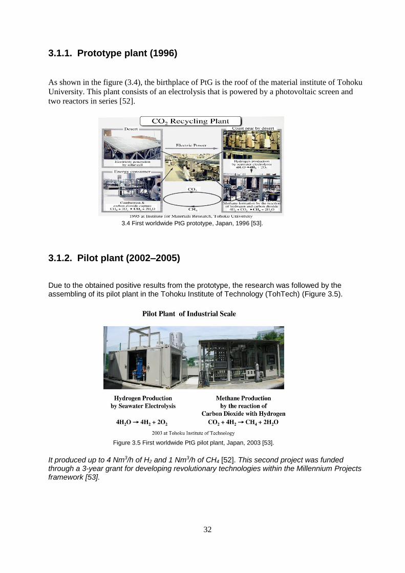
3.1.1. Prototype plant (1996)
As shown in the figure (3.4), the birthplace of PtG is the roof of the material institute of Tohoku
University. This plant consists of an electrolysis that is powered by a photovoltaic screen and
two reactors in series [52].
3.4 First worldwide PtG prototype, Japan, 1996 [53].
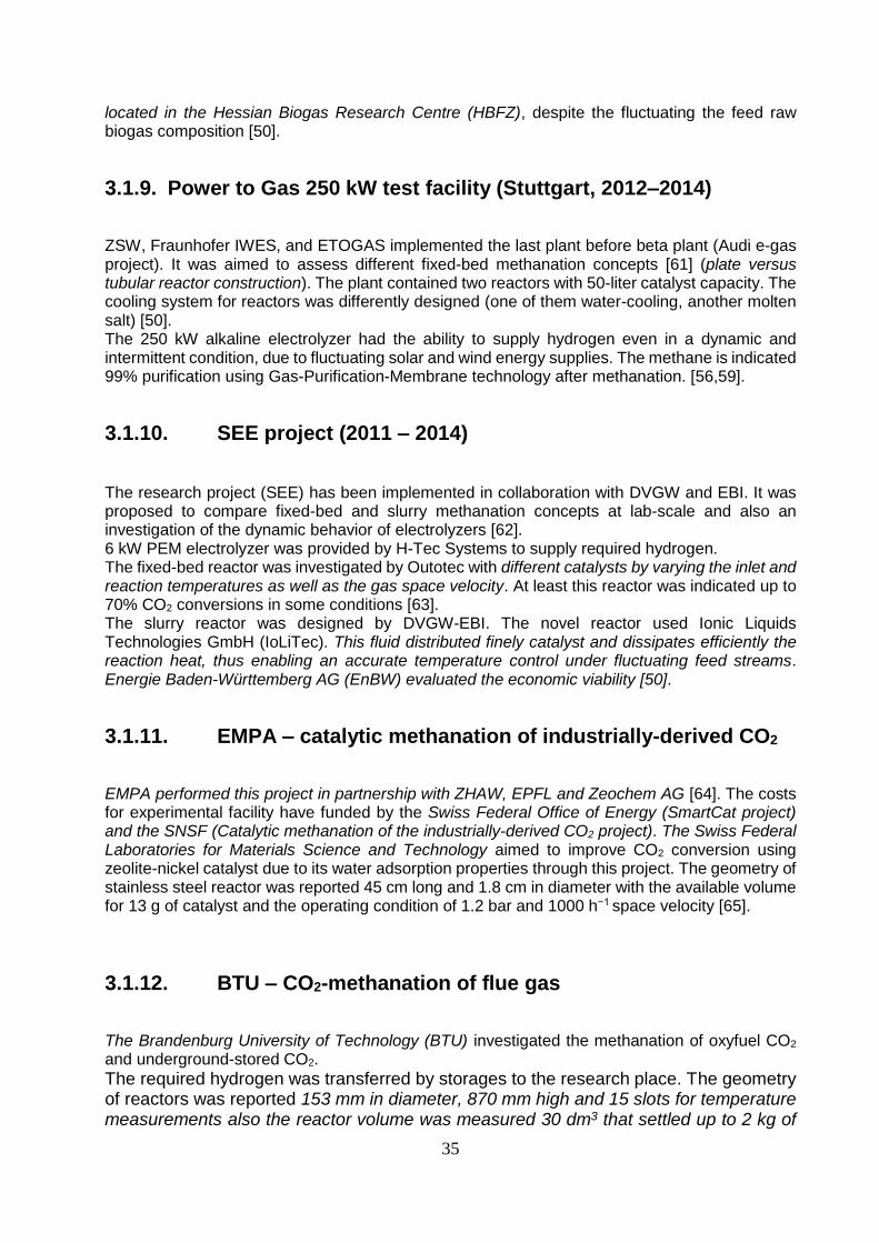
3.1.2. Pilot plant (2002–2005)
Due to the obtained positive results from the prototype, the research was followed by the assembling of its pilot plant in the Tohoku Institute of Technology (TohTech) (Figure 3.5).
Figure 3.5 First worldwide PtG pilot plant, Japan, 2003 [53].
It produced up to 4 Nm3/h of H2 and 1 Nm3/h of CH4 [52]. This second project was funded through a 3-year grant for developing revolutionary technologies within the Millennium Projects framework [53].

33
3.1.3. Desert Research Institute – CO2 recycling via reaction with hydrogen
The Desert Research Institute (DRI), in 2009, started a pilot PtG project to estimate its limitations and challenges against benefits of catalytic methanation (foundation by RCO2 AS). The system was installed in a portable trailer in Reno, United States. The pure hydrogen (99.999%) was supplied by a 5kW PEM electrolyzer, which was powered by a 1.0kW Siemens PV array and located in a trailer. This unit was able to supply H2 up to 600 cm3/h at 200 psi. The carbon dioxide was fed to the reactor via a mixture of 2% CO2 and N2, due to achieving various experimental operation with maximal temperature controlling.
Figure 3.6 The portable pilot plant of PtG structured by DRI into a trailer [54].
The feed gas after preheating flowed through the reactor (with Heat Guard) from top to bottom. The temperature of reactor was monitored by three transmitters, two transmitters checked the top and bottom of catalyst temperature and the third transmitter checked combustion chamber (Figure 3.6). During the operation the feed ratio 4/1 between H2/CO2 was kept constant and the feed total flow rate was varied. The baseline parameters for experiments were considered as the reactor temperature of 300 °C and the space velocity approximately 9000 h-1, but the Space velocities were changed in steps of 25% of the baseline during experiments. The maximum conversion of CO2 recorded 60% in the temperature range of 300–350 °C and 10,000 h−1 space velocity [54].
3.1.4. ETOGAS – Audi e-gas plant
The Audi e-gas plant is located in Werlte (Germany) and is the first and biggest (6 MW) commercial PtG plant. It was the result of a successful collaboration between Audi AG, ETOGAS GmbH (formerly known Solar Fuel GmbH), the Centre for Solar Power and Hydrogen Research Baden-Württemberg (ZSW), the Fraunhofer Institute for Wind Energy and Energy System Technology (Fraunhofer IWES) and EWE Biogas GmbH & Co. KG (2009-2013) [55]. As a manufacturer in this collaboration, ETOGAS designed the research plant of this project in Stuttgart and ZSW was the chief developer [56]. The required hydrogen is supplied by 3×2.0 MW alkaline electrolyzers that are powered by generated electricity from an offshore wind park in the North Sea. The required CO2 is supplied by EWE Biogas GmbH & Co. KG. Amine scrubbing technology was applied to separate CO2 from raw biogas [57]. A single Isothermal fixed-bed reactor was recruited for the catalytic methanation [58,50].

34
3.1.5. Power to Gas α-plant with air purification (Stuttgart, 2009)
The first research (α-plant) step of Audi e-gas project was done by ZSW (Figure 3.7). It was aimed at the basic feasibility of the PtG process. Hence, a 25 kW electrolyzer and a CO2 ambient air purification system was installed as a mobile plant in a container [59].
Figure 3.7 The 25kW α-plant shows the feasibility of the P2G process [59].
3.1.6. Power to Gas α-plant with CO2 from biogas purification (Werlte,2010–2011)
The second research (α-plant) step of Audi e-gas project was supposed to investigate the methanation using carbon dioxide that was produced by pressure swing adsorption (PSA) from the EWE Biogas plant. Hence, in this research phase Audi AG, ETOGAS GmbH, EWE Biogas GmbH & Co. KG cooperated at Werlte, Germany [60,50].
3.1.7. Power to Gas α-plant with raw biogas (Morbach, 2011)
The third research (α-plant) step of Audi e-gas project was aimed to determine the feasibility of methanation using raw biogas instead of pure CO2. With joining Juwi AG to the previous partners at Werlte, it was proved that direct methanation of biogas is technically possible in a PtG plant [60,50].
3.1.8. Power to Gas α-plant in long period operation with raw biogas (Bad Hersfeld, 2012)
The fourth research (α-plant) step of Audi e-gas project was in collaboration with ZSW. It was aimed to test locally long period methanations with raw biogas from an agricultural biogas plant
35
located in the Hessian Biogas Research Centre (HBFZ), despite the fluctuating the feed raw biogas composition [50].
3.1.9. Power to Gas 250 kW test facility (Stuttgart, 2012–2014)
ZSW, Fraunhofer IWES, and ETOGAS implemented the last plant before beta plant (Audi e-gas project). It was aimed to assess different fixed-bed methanation concepts [61] (plate versus tubular reactor construction). The plant contained two reactors with 50-liter catalyst capacity. The cooling system for reactors was differently designed (one of them water-cooling, another molten salt) [50]. The 250 kW alkaline electrolyzer had the ability to supply hydrogen even in a dynamic and intermittent condition, due to fluctuating solar and wind energy supplies. The methane is indicated 99% purification using Gas-Purification-Membrane technology after methanation. [56,59].
3.1.10. SEE project (2011 – 2014)
The research project (SEE) has been implemented in collaboration with DVGW and EBI. It was proposed to compare fixed-bed and slurry methanation concepts at lab-scale and also an investigation of the dynamic behavior of electrolyzers [62]. 6 kW PEM electrolyzer was provided by H-Tec Systems to supply required hydrogen. The fixed-bed reactor was investigated by Outotec with different catalysts by varying the inlet and reaction temperatures as well as the gas space velocity. At least this reactor was indicated up to 70% CO2 conversions in some conditions [63]. The slurry reactor was designed by DVGW-EBI. The novel reactor used Ionic Liquids Technologies GmbH (IoLiTec). This fluid distributed finely catalyst and dissipates efficiently the reaction heat, thus enabling an accurate temperature control under fluctuating feed streams. Energie Baden-Württemberg AG (EnBW) evaluated the economic viability [50].
3.1.11. EMPA – catalytic methanation of industrially-derived CO2
EMPA performed this project in partnership with ZHAW, EPFL and Zeochem AG [64]. The costs for experimental facility have funded by the Swiss Federal Office of Energy (SmartCat project) and the SNSF (Catalytic methanation of the industrially-derived CO2 project). The Swiss Federal Laboratories for Materials Science and Technology aimed to improve CO2 conversion using zeolite-nickel catalyst due to its water adsorption properties through this project. The geometry of stainless steel reactor was reported 45 cm long and 1.8 cm in diameter with the available volume for 13 g of catalyst and the operating condition of 1.2 bar and 1000 h−1 space velocity [65].
3.1.12. BTU – CO2-methanation of flue gas
The Brandenburg University of Technology (BTU) investigated the methanation of oxyfuel CO2 and underground-stored CO2.
The required hydrogen was transferred by storages to the research place. The geometry of reactors was reported 153 mm in diameter, 870 mm high and 15 slots for temperature measurements also the reactor volume was measured 30 dm3 that settled up to 2 kg of
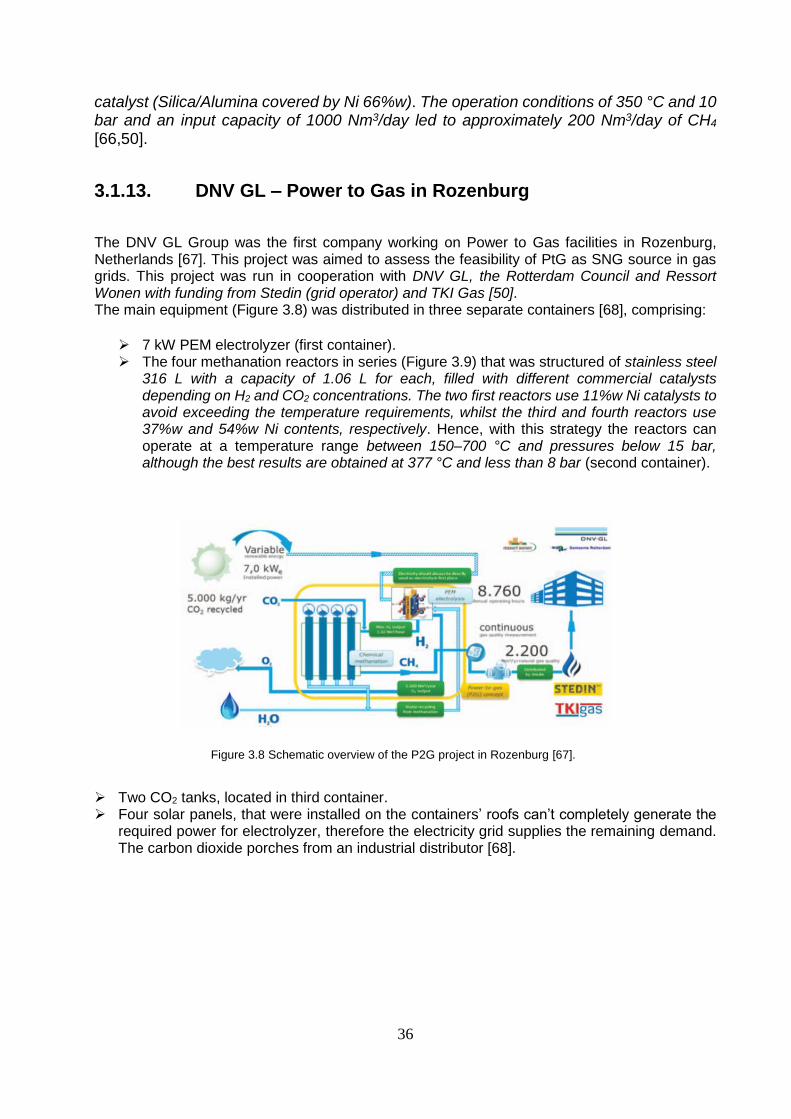
36
catalyst (Silica/Alumina covered by Ni 66%w). The operation conditions of 350 °C and 10 bar and an input capacity of 1000 Nm3/day led to approximately 200 Nm3/day of CH4 [66,50].
3.1.13. DNV GL – Power to Gas in Rozenburg
The DNV GL Group was the first company working on Power to Gas facilities in Rozenburg, Netherlands [67]. This project was aimed to assess the feasibility of PtG as SNG source in gas grids. This project was run in cooperation with DNV GL, the Rotterdam Council and Ressort Wonen with funding from Stedin (grid operator) and TKI Gas [50]. The main equipment (Figure 3.8) was distributed in three separate containers [68], comprising:
7 kW PEM electrolyzer (first container). The four methanation reactors in series (Figure 3.9) that was structured of stainless steel
316 L with a capacity of 1.06 L for each, filled with different commercial catalysts depending on H2 and CO2 concentrations. The two first reactors use 11%w Ni catalysts to avoid exceeding the temperature requirements, whilst the third and fourth reactors use 37%w and 54%w Ni contents, respectively. Hence, with this strategy the reactors can operate at a temperature range between 150–700 °C and pressures below 15 bar, although the best results are obtained at 377 °C and less than 8 bar (second container).
Figure 3.8 Schematic overview of the P2G project in Rozenburg [67].
Two CO2 tanks, located in third container. Four solar panels, that were installed on the containers’ roofs can’t completely generate the
required power for electrolyzer, therefore the electricity grid supplies the remaining demand. The carbon dioxide porches from an industrial distributor [68].

37
Figure 3.9 Reactors of methanation [68].
3.1.14. HSR-IET – Power-to-Methane HSR
The Institute for Energy Technology of the Hochschule für Technik Rapperswil (HSR-IET) defined and developed the first Power to Gas plants in Swiss, Rapperswil (Figure 3.10). The pilot project was aimed for developing simulation models to estimate the future role of Power to Gas in the Swiss energy supply. In this project, for the first time within PtG plants, the methanation heat was conducted and applied in an ambient-CO2 absorption process [69]. The hydrogen was provided by the local power company Elektrizitätswerk Jona-Rapperswil AG (EWJR) and the CO2 was separated from the air and collected up to 4 kg/day [70].
Figure 3.10 The pilot and demonstration Power-to-Methane plant HSR [69].
3.1.15. Hitachi Zosen – CO2 Conversion to Methane Project
The first facility in Thailand approaching CO2 Conversion to Methane launched in 2012. The results were supposed to apply in the simulation and design of the main plant with a methane production of 1000 Nm3/h. The partner’s group in this research were Hitachi Zosen Corporation, Daiki Ataka Engineering Co. and PTT Exploration and Production Public Company Limited (PTTEP). The CO2 generated during extraction of natural gas from natural reservoirs was considered as the main source for this project [71]. The required hydrogen was supplied by alkaline electrolyzers fed with desalinated seawater. The first phase of the project was designed using tubular reactors that operated at 200 °C. The catalyst based on zirconia-samarium, with nickel as an active material, which was developed by Hashimoto et al. [72].
38
3.1.16. JKU Linz-EI – PtG in Austria
The Energy Institute of the Johannes Kepler University Linz (JKU Linz-EI) took part in four connected projects for developing a complete chain of Power to Gas systems in Austria. These projects have been running in cooperating with the Vienna University of Technology (TU Wien), the Austrian Association for Gas and Water (ÖVGW), the Association of Gas and District Heating Supply Companies (FGW), Montan University of Leoben and the Christof Group.
Wind2Hydrogen (2014– 2016) built a 100 kW pilot plant with 12 PEM electrolyzers (section Hydrogen projects, Table 3.2) [73].
EE-Methan aus CO2 (2013–2016) develops catalytic methanation [74]. OptFuel (2013–2016) focuses on hydrogen production through fermentation and on the
purification requirements for its later conversion into methane (partly biological methanation, so it won’t investigate more) [75].
Underground Sun Storage (2013–2016) studies the storage of the generated gas (section methane-hydrogen projects, Table 3.3).
The main goal of EE-Methan project is to develop a ceramic honeycomb catalyst adapted to industrial CO2 sources for increasing the lifetime about 10% with respect to commercial catalysts [74].
3.1.17. Paul Scherrer Institute – RENERG2
The RENERG2 project (Renewable Energies for Future Energy Supply) was defined to investigate electrolysis, methanation, combustion fundamentals, refueling and economics for using renewable energy surplus in mobility sector [76]. The project’s partners included EMPA, the Swiss Federal Institute of Technology Zurich (ETH Zurich), the Zurich University of Applied Sciences (ZHAW), and EPFL. This project was funded by the Competence Centre for Energy and Mobility (CCEM) [76,50]. The methanation research was dedicated to the Paul Scherrer Institute using its bubbling fluidized bed methanation process (GanyMeth) [50].
3.1.18. Sunfire – HELMETH
The HELMETH project (Integrated High-Temperature Electrolysis and Methanation for Effective Power to Gas Conversion) was in cooperating with Sunfire GmbH (administrative), KIT (project conductor), Politecnico di Torino (PoliTo), the European Research Institute of Catalysis AISBL (ERIC), Turbo Service Torino spa (TS-Torino), National Technical University of Athens (NTUA), DVGW. This project was aimed to reach efficiencies above 85% in Power to Gas technologies by uniting high-temperature electrolysis and CO2 methanation [77]. The electrolysis research was supposed to be done by the ERIC using a 15 kW SOEC, working at 800 °C and 15 bar [50]. The methanation process consisted of two reactors in series at 300 °C and 30 bar and intermediate water removal and also adding composite oxides to the γ-Al2O3 substrate, as catalyst stabilizer [78,79].

39
3.2. Hydrogen projects
The hydrogen plants have from efficiency aspect (Figure 3.4) more advantages than methanation plants. This fact has created enough motivation for energy suppliers. Therefore, they have been structuring also many hydrogen plants beside the methanation plants. The following presents an overview of hydrogen plants in European Union countries (Table 3.2), [51].
Project Name
Location Application
H2production (Nm3/h)
Installed power
(kW)
Electrolysis
technique Involved parties
Auersthal (AT) - Wind2Hydrogen
Auersthal, Austria
Mobility
Gas grid
Unknown 100 PEM OMV Gas & Power, Fronius, EVN AG, HyCentA Research GmbH und das
Energieinstitut der Johannes Kepler Universität Linz
Brugg (CH) - PostBus Hydrogen Bus
Stuttgart, Germany
Mobility 60 315 Alkaline Carbagas (Swiss sibsidiary of Air Liquide), Hydrogenics, PostBus
Aragon (E) – ITHER Brugg, Switzerland
Aragon, Spain
Mobility Unknown 4070
Alkaline & PEM
unknown
Corsica (F) - MYRTE Ajaccio, Corsica, France
Power generation, Power storage
23 150 PEM AREVA, CEA, University of Corsica, CNRS
Abalone Energie Nantes (F) Nantes, France
Power generation, Power storage
Unknown 0 unknown Regio Pays de la Loire
Don Quichote (BE) - Colruyt Halle, Belgium
Mobility (forklifts)
30 150 PEM WaterstofNet, Colruyt, Hydrogenics, Thinkstep, Icelandic New Energy, FAST, TÜV Rheinland
Leicestershire (UK) – Hari
project Leicestershire, United Kingdom
Power generation, Power storage
Unknown
36 Alkaline Loughborough University
Rotherham (UK) - hydrogen
mini-grid project Rotherham, United Kingdom
Power generation, Power storage
Unknown 30 unknown Unknown
Fife (UK) - Levenmouth
Community Energy Project Fife, Scotland
Mobility 370 Alkaline & PEM
Bright Green Hydrogen Ltd,Fife Council, Toshiba, Leven Valley Development Trust, Fife College, BOC (for hydrogen transport), Green Business Fife, Community Energy Scotland and the Scottish Hydrogen and Fuel Cell
Association (SHFCA).
Aberdeen (UK) - Hydrogen Bus
Project Aberdeen, Scotland
Mobility 180 1000 Alkaline
BOC, Scottish & Southern Energy Power Distribution (SSEPD), Scotland Gas Networks (SGC), Van Hool, Ballard Power Systems, Dantherm, First,
Stagecoach, Scottish Government, Scottish Enterprise, Element Energy, Planter Energie, Innovate UK, Aberdeen City Council
SamsØ (DK) SamsØ, Denmark
Mobility
Unknown
20
Alkaline
SamsØ Energy Academy
Freiburg (D) – H2Move Freiburg, Germany
Mobility 6
40
PEM Fraunhofer ISE, Ministerium für Umwelt, Klima und Energiewirtschaft Baden-Württemberg, Stadt Freiburg, badenova, NOW GmbH
Mainz (D) Mainz, Germany
Mobility, Power generation, Power storage, Industry
1000 3900 PEM Stadtwerke Mainz AG, Linde AG, Siemens AG, Hochschule RheinMain
Frankfurt am Main (D) - Thuga Frankfurt am Main, Germany
60 315 PEM
Hanau (D) Hanau, Germany
Power generation
4 35 PEM SolviCore GmbH & Co. KG, Mainova AG, Stadtwerke Hanau GmbH, Hochschule RheinMain aus Rüsselsheim
Ibbenburen (D) – RWE Ibbenbüren, Germany
Gas grid, heat
30 150 PEM WESTNETZ GmbH
Hamburg-Schnackenburgallee
(D) Hamburg-Schnackenburgallee, Germany
Mobility 30 185 PEM Shell, NOW GmbH, CEP-Clean-Energy-Partnership
Hamburg-Hafencity (D) –
Vattenfall Hafencity, Hamburg, Germany
Mobility 120 630 Alkaline Bundesministerium für Verkehr, Bau und Stadtentwicklung, CEP-Clean Energy Partnership, NOW GmbH, Shell
Hamburg-Reitbrook (D) –
WindGas Hamburg Reitbrook, Hamburg, Germany
Gas grid
290 1000 PEM
Uniper, Hydrogenics, GmbH, SolviCore GmbH & Co. KG, Fraunhofer Institute for Solar Energy, Systems ISE and German Aerospace Center (DLR), NOW
GmbH, Greenerity
Grapzow (D) – RH2 WIND Grapzow, Germany
CHP & gas grid 210
1000 Alkaline NOW GmbH, Haas Engineering, Architekturbüro Karsten Klünder. Hydrogenics, Senergie
Prenzlau (D) – ENERTRAG
AG Prenzlau, Germany
Mobility & power generation / storage
120 600 Alkaline
Vattenfall Europe Innovation GmbH, Total, DB Mobilty Network Logistics, Bundesministerium für Verkehr, Bau und Stadtentwicklung, European Union,
Land Brandenburg, PTJ, Investitionsbank des Landes Brandenburg, Fachhochschule Stalsund, Brandenburgischer Technischer Universität
Berlin Airport (D) - H2BER Berlin Airport, Germany
Mobility, Power generation, Power storage, anticipates CHP(combined heat and
power plant)
90 500 Alkaline Total Deutschland GmbH, Enertrag AG, Linde AG, McPhy Energy, 2G Energy
Cottbus (D) Cottbus, Germany
Unknown 20-30
150 Alkaline Wassertoff-Forschungszentrum Brandenburgische Technische Universität Cottbus
Table 3.2 The operating hydrogen PtG plants in European Union countries [51].

40
Figure 3.4 Sankey diagram of the PtG process efficiency, [11].
3.3. Methane-hydrogen projects
As expressed before, some of the plants are designed by engineers in a way, which can simultaneously provide methane and hydrogen as products for customers (Figure 3.2). In the following, the methane-hydrogen plants (Table 3.3) in European Union countries [51] are listed.
Project
Location
Target
H2/SNG production (Nm3/h)
Electrolysis technique Installed power (kW)
Methanation principle CO2 Source
Involved parties
Vienna (AT) - Underground Sun Storage [108] Vienna, Austria
Storage
120 /Unknown
Alkaline 600
Chemical Atmosphere, biogas or industrial plant
RAG, University of Leoben, University of Natural Resources and Life Siences Vienna, Energy Institute at Johannes Kepler University Linz, Verbund, Axiom Angewandte Prozesstechnik, Nafta, Etogas, German Technical and Scientific Association for Gas and Water or DVGW, Hychico
Puglia region (I) - INGRID Project Troia, Pulgia, Italy
Gas grid (Regional distribution)
Unknown/Unknown
Alkaline 1000
Chemical (Modular mili-structured catalytic methanation reactors) atmosphere
McPhy Energy S.A. Hydrogenics, Tecnalia, RSE, Enel Distribuzione, Arti
Dunkerque (F) - GRHYD project Dunkerque, France
Mobility, Gas grid
10-15/Unknown Unknown Unknown
n/a Unknown
GrDF, NVERT, AREVA Hydrogène et Stockage de l’énergie, CEA, McPhy Energy, INERIS, CETIAT and CETH2
Kirchheimbolanden (D) - RegEnKibo Kirchheimbolanden, Germany
Gas grid
Unknown/Unknown Unknown Unknown Unknown Unknown
e-rp GmbH, KIT, DVGW-Forschungstelle am Engler-Bunte-Institut des KIT, Transferstelle für Rationelle und Regenerative Energienutzung Bingen (TSB), Viessman Gruppe, Stadt Kirchheimbolanden
Allendorf, Eder (D) - BioPower2Gas Allendorf, Eder, Germany
Gas grid
60-220/15-55
PEM 1100
Biological Unknown
MicrobEnergy GmbH, EnergieNetz Mitte GmbH, EAM EnergiePlus GmbH, CUBE Engineering GmbH
Table 3.3 The operating methane-hydrogen PtG plants in European Union countries [51].

41
Chapter 4
Modeling and simulation
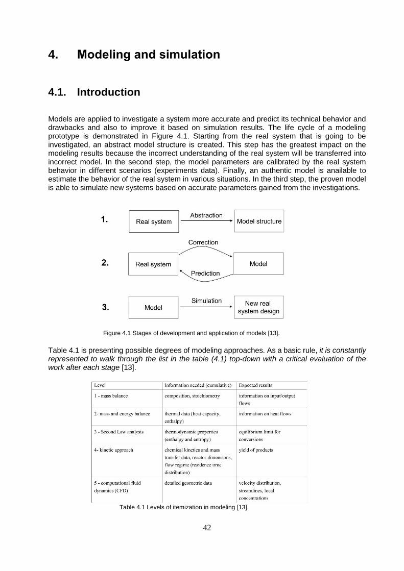
42
4. Modeling and simulation
4.1. Introduction
Models are applied to investigate a system more accurate and predict its technical behavior and drawbacks and also to improve it based on simulation results. The life cycle of a modeling prototype is demonstrated in Figure 4.1. Starting from the real system that is going to be investigated, an abstract model structure is created. This step has the greatest impact on the modeling results because the incorrect understanding of the real system will be transferred into incorrect model. In the second step, the model parameters are calibrated by the real system behavior in different scenarios (experiments data). Finally, an authentic model is anailable to estimate the behavior of the real system in various situations. In the third step, the proven model is able to simulate new systems based on accurate parameters gained from the investigations.
Figure 4.1 Stages of development and application of models [13].
Table 4.1 is presenting possible degrees of modeling approaches. As a basic rule, it is constantly represented to walk through the list in the table (4.1) top-down with a critical evaluation of the work after each stage [13].
Table 4.1 Levels of itemization in modeling [13].

43
4.2. Modeling and simulation in methanation
Today, modeling and simulation are an essential phase of research and development not only in methanation concepts, even all chemical engineering branch and science. Practically, modeling and simulation works apply in the four scopes including process design, process evaluation, process optimization, and process adaptation [10].
Process design
The computer-aided process design is a major task of engineers in chemical engineering. As discussed in chapter 2, the exothermal identity of the methanation reactions causes the reactor temperature to be especially noteworthy. The temperature behavior of a designed reactor is depending on reactor design (e.g. diameter, length, cooling, and insulation), process design (residence time, the composition of the feed gas), and the catalyst (activity, dilution) [10].
Process evaluation
The evaluation of an equipment like methanation reactor is quantitatively translated to the performance of reaction from different aspects (e.g. selectivity [80]). The simulation-based evaluation studies require process parameters such as temperature profile, production rate, composition, and transferred heat rates of reactor and exchangers. Also, these evaluations can be done for a whole process (e.g. PtG plant). In section 4.4 a novel simulation-based evaluation (Distance of Equilibrium State) for a sample methanation reactor using programming capabilities in Microsoft ® Excel ® is presented.
Process optimization
As mentioned before, with increasing demand for applying methanation concepts as a chemical storage of renewably-generated power (Power to Gas), simulation studies try to optimize the reactor dynamic performances. Hence, simulation models are used to predict the consequences caused by power or feed fluctuations [81,82]) and also to improve control strategies [83].
Process adaptation
This subject has practically been applied within the recent CO2 methanation processes (Power to Gas plants). Therefore, the past methanation concepts (particularly CO-methanation) is adapted to the customized CO2-methanation processes, which are adequated for applying in PtG plants by modeling and simulation developments [84,85].
4.3. Reactor modeling
The industrial methanation reactor is known as a complex process because of the simultaneous occurrences of gas phase reaction that happen very quickly. Hence, simulation and modeling of such a process before the industrial plant designing seems to be vital. According to Table 4.1, to simulate a reactor system, its issues like mass transfer, heat transfer (exothermic reaction), the occurrence of secondary reactions such as water gas shift reaction, the kinetic approach, etc. must be considered. Therefore, the characteristics of models very clearly depend on the purposes of modeling and simulation task. Main characteristics are known to be the time resolution of the model, the reactor dimension, the phase modeling, the temperature characteristics, the kinetic approach, and the software [10]. In Tables 4.2, 4.3, and 4.4 a selection of the models is presented

44
with respect to their main characteristics concerned to the fixed-bed, the three-phase, fluidized-bed, the fixed-bed tube bundle, and the fixed-bed structured methanation reactors respectively.
4.3.1. Time analysis
Due to defined requirements, steady state (S.S.) or dynamic reactor models can be approached. The dynamic reactor models include also derivations of time instead of spatial derivatives equations only in the stationary models. Accordingly, these models can be applied to analyze the methanation reaction.
4.3.2. Reactor dimensions
Briefly, reactor models may be considered with zero to three spatial dimensions.
If designers create situations within reactors that mentioned specifications are just a function of time, not geometry, then they can apply zero-dimensional models to describe the real system, such as continuous stirred tank reactors when being perfectly mixed. However, a chain of zero-dimensional models can be placed in series to obtain a one-dimensional (axial) profile.
For fixed-bed reactors particularly, the one-dimensional reactor models are normally implemented. It is clear, that the axial profile of gas species and temperature will especially be investigated as the only geometrical characteristic in case of plug flow reactors. The radial property changes are often neglected because the plug flow reactors assumption of constant radial temperature and concentrations will practically be acceptable.
Two-dimensional models require much more computational effort for solving the differential equations. The one-dimensional models are more efficient to evaluate qualitative attitudes of the real system. However, the two-dimensional models reflect more detailed picture that is more suitable for quantitative evaluations [86].
To solve the equations of three-dimensional models highest level of computational calculations has to be applied. They are vital especially for detailed optimization and design. But there are not necessarily big differences between two and three-dimensional simulations in some cases [87,88].
4.3.3. Phase modeling
The conventional fixed bed methanation reactors and three phase reactors are categorized as heterogeneous reactors in this science because they contain gas phase (reactants and products) solid phase (catalyst) and a liquid phase (just for three-phase reactors) that usually are inert heat transfer fluids. But in contrast, fluidized-bed reactors with some assumption and estimations (e.g. effect of external mass transfer and pore diffusion are negligible [10]) can suppose as a two or even one continuum (pseudo-homogeneous) phase because these assumptions have the advantages of easier modeling process, however it will include certainly the inaccuracy in the outputs from model. The criteria of Mears [90] are usually considered by engineers to realize the acceptable assumptions for each system [89].

45
4.3.4. Temperature characteristic
As discussed before, control of the temperature due to a high-exothermic heat of the reactions is a very significant issue that must be considered from the designing phase of the methanation processes and reactors. For methanation modeling, the temperature profile often is estimated by an ideal temperature profile. Ideal fixed-bed reactors without cooling typically display adiabatic temperature profiles, also, ideal fluidized-bed and three-phase reactors with cooling mechanisms are demonstrated isothermal temperature profiles (section 2.2.3) [10,8].
4.3.5. Kinetics approach
As mentioned in section (2.1.1), because processes cannot practically fulfill the equilibrium states during the reaction (requirement of infinite time or very slow interactions progress), kinetics descriptions have been developed to describe the system through the non-equilibrium states. Additionally, there are infinite non-equilibrium states that every reaction with a particular catalyst and condition (i.e. temperature, pressure, composition, etc.) is able to show. There are several methanation kinetics in the literature that useing a particular mechanism and method (e.g. power law, Langmuir-Hinshelwood etc.) developed by researchers. For example, in Figure 4.2 the developed CO2-hydrogenation kinetic by Weatherbee and Bartholomew [12] (1982) is illustrated. As described in section 2.1.2, this kinetic was developed based on their mechanism (Figure 2.8) to fit the determined experimental data. Also, useful overviews about different kinetic approaches are presented by Kopyscinski [91], Mills and Steffgen [49], and Vannice [38]. Xu and Froment kinetic [92] for FB-reactors and Kopyscinski kinetic [91] for fluidized and three phase reactors seems to be the best chooses, according to Tables 4.2, 4.3 and 4.4. Franz Koschany et al. [93] developed several kinetics as rate equations using power law and Langmuir–Hinshelwood–Hougen–Watson (LHHW) approaches for a series of NiAl(O)x catalysts with varying Ni/Al ratio.
4.3.6. Software
As it is observable from tables 4.2, 4.3 and 4.4 a group of simulation and modeling software is available to be applied for solving the differential equations due to methanation reactor modeling. These tools include Aspen Plus, Aspen Dynamics, Modelica Fluid, Femlab, Fortran, ACM, Matlab, etc. Matlab is the most common software for this purpose.
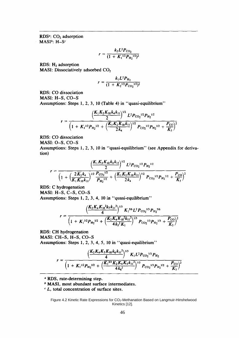
46
Figure 4.2 Kinetic Rate Expressions for CO2-Methanation Based on Langmuir-Hinshelwood
Kinetics [12].

47
Time Reactor Phase modeling Temperature Kinetic approach Software Authors
resolution dimensions characteristic
dyn. 1D Heterogeneous (therm.)
Adiabatic (supposed) – (equilibrium)
Modelica Fluid Bader et al.
stat. 3D Pseudo-homogeneous Polytropic Measured (1st order) Femlab Cao et al.
dyn. 1D Pseudo-homogeneous Adiabatic n.s. Fortran Dissinger et al.
dyn. 1D Pseudo-homogeneous Adiabatic van Herwijnen et al. n.s. van Doesburg et al.
stat. 1D Pseudo-homogeneous Isothermal Kopyscinski Aspen Plus Er-rbib et al.
dyn. 1D Pseudo-homogeneous Isothermal Kopyscinski ACM Güttel
stat. 1D Heterogeneous (cat. isoth.) Adiabatic Xu and Froment Matlab Khorsand et al.
dyn. 1D Pseudo-homogeneous Polytropic Xu and Froment
Aspen Dynamics Li et al.
dyn. 1D Heterogeneous (therm.) Polytropic Measured n.s. Lunde
dyn. 1D Heterogeneous (therm.) Adiabatic Xu and Froment Matlab Matthischke and Rönsch
stat. 1D Heterogeneousa Adiabatic Xu and Froment (refit) n.s. Parlikkad et al.
dyn. 0D Heterogeneous (therm.) Adiabatic – (equilibrium) Matlab Rönsch et al.
stat. 1D Heterogeneous Polytropic Xu and Froment Matlab Schlereth and Hinrichsen
stat. 2D Pseudo-homogeneous Polytropic Xu and Froment Matlab Schlereth and Hinrichsen
stat. 1D Pseudo-homogeneous Adiabatic van Doesburg. (refit) – Wedel and Luss
Table 4.2 Model characteristics of fixed-bed methanation reactors [10].
Time Reactor Phase modeling Temperature Kinetic approach Software Authors
resolution dimensions characteristic
stat. 1D Three phases, pseudo-homogeneous Isothermal Measured Matlab Götz
(1st
order)
stat. 1D (0D i.s.) Two phases, pseudo-homogeneous dense phase Isothermal (supposed) Measured n.s. Cobb and
Streeter
(1st
order)
stat. 1D Two phases, pseudo-homogeneous dense phase Defined profile Kopyscinski Athena Kopyscinsk
i et al.
dyn. 2D/3Da Two phases, heterogeneous dense phase Isothermal Kopyscinski Open FOAM
Liu and
Hinrichsen
Table 4.3 Model characteristics of three-phase and fluidized-bed methanation reactors [10].
Time Reactor Phase modeling Temperature Kinetic approach Software Authors
resolution dimensions characteristic
stat. 1D Pseudo-homogeneous Polytropic Xu and Froment AMPL El Sibai et al.
stat./dyn. 1D Pseudo-homogeneous Polytropic Kopyscinski Aspen
Dynamics Jürgensen et al.
dyn. 1D (0D i.s.) Pseudo-homogeneous Polytropic Xu and Froment Matlab Kang and Lee
dyn. 1D Heterogeneous
(cat. isoth.) Defined profile Lunde (refit) LIMEX Brooks et al.
dyn. 1D Heterogeneous Polytropic Sughrue and Bartholomew and
Weatherbee and Bartholo- mew gProms Sudiro et al.
Table 4.4 Model characteristics of the fixed-bed tube bundle and structured methanation reactors [10].
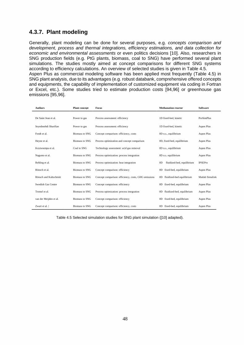
48
4.3.7. Plant modeling
Generally, plant modeling can be done for several purposes, e.g. concepts comparison and development, process and thermal integrations, efficiency estimations, and data collection for economic and environmental assessments or even politics decisions [10]. Also, researchers in SNG production fields (e.g. PtG plants, biomass, coal to SNG) have performed several plant simulations. The studies mostly aimed at concept comparisons for different SNG systems according to efficiency calculations. An overview of selected studies is given in Table 4.5. Aspen Plus as commercial modeling software has been applied most frequently (Table 4.5) in SNG plant analysis, due to its advantages (e.g. robust databank, comprehensive offered concepts and equipments, the capability of implementation of customized equipment via coding in Fortran or Excel, etc.). Some studies tried to estimate production costs [94,96] or greenhouse gas emissions [95,96].
Authors Plant concept Focus Methanation reactor Software
De Saint Jean et al. Power to gas Process assessment: efficiency 1D fixed-bed, kinetic ProSimPlus
Seyedmehdi Sharifian Power to gas Process assessment: efficiency 1D fixed-bed, kinetic Aspen Plus
Fendt et al. Biomass to SNG Concept comparison: efficiency, costs 0D n.s., equilibrium Aspen Plus
Heyne et al. Biomass to SNG Process optimization and concept comparison 0D, fixed-bed, equilibrium Aspen Plus
Koytsoumpa et al. Coal to SNG Technology assessment: acid gas removal 0D n.s., equilibrium Aspen Plus
Nagumo et al. Biomass to SNG Process optimization: process integration 0D n.s. equilibrium Aspen Plus
Rehling et al. Biomass to SNG Process optimization: heat integration 0D fluidized-bed, equilibrium IPSEPro
Rönsch et al. Biomass to SNG Concept comparison: efficiency 0D fixed-bed, equilibrium Aspen Plus
Rönsch and Kaltschmitt Biomass to SNG Concept comparison: efficiency, costs, GHG emissions 0D fluidized-bed equilibrium Matlab Simulink
Swedish Gas Centre Biomass to SNG Concept comparison: efficiency 0D fixed-bed, equilibrium Aspen Plus
Tremel et al. Biomass to SNG Process optimization: process integration 0D fluidized-bed, equilibrium Aspen Plus
van der Meijden et al. Biomass to SNG Concept comparison: efficiency 0D fixed-bed, equilibrium Aspen Plus
Zwart et al. [ Biomass to SNG Concept comparison: efficiency, costs 0D fixed-bed, equilibrium Aspen Plus
Table 4.5 Selected simulation studies for SNG plant simulation ([10] adapted).

49
4.4. Basic simulation of the methanation reactor in Excel
4.4.1. System introduction
The final purpose of this novel simulation-based work is the evaluation of the reactor working state and comparison with equilibrium state using the Distance to Equilibrium State (DES) parameter (pδ_eq(p_i,T)). This kind of simulation is able to evaluate the working reaction’s state that in concept development or catalyst and mechanism investigation is very important. The catalytic methanation reactor which is going to be investigated is an adiabatic reactor (Figure 4.3) with one feed (S2) and product (S3) stream that operates in a steady state profile and isobaric process. Also, the components comprising CO2, CH4, CO, H2, and H2O are reported as the substances in the gas form that ideal gas mixture theories can well define their properties during the reaction process.
S2 = 0.745 (mole/min), Xi
REACTOR
---------->
T2=617.15 K S3=? , Yi
P2=P3= 1013250 Pa (Isobaric)
-----------> T3=?
Figure 4.3 The catalytic adiabatic methanation reactor.
The composition of substances in the feed stream (H2/CO2=11.6952) is presented in Table 4.6.
Species
xi (mole/mole)
Xi(kg/kg)
CO2 0,0771 0,6060 CH4 0,0058 0,01662 CO 0,0018 0,009004 H2 0,9017 0,3246 H2O 0,0136 0,04376 Sum 1,0000 1,0000
Table 4.6 composition of the feed stream of the sample reactor, (Experimental Data) [109].
4.4.2. Thermodynamic property
The thermodynamic properties (e.g. molecular weights (M), conventional enthalpy H*, conventional entropy (S*)) of the component in this modeling will be calculated by NASA polynomial macro in Excel based on International Standard Temperature 25 °C and SI unit system. The generated properties by excel for the feed stream (S2) are collected in Table 4.7. The advantage of conventional properties (Eq. (14)&(15)) is the easier calculations without entering the reaction enthalpy in the heat balance and equilibrium constant (Kp) equations [13,97].
h* (p,T) = ∆h°f,298 + h (p,T) – h (p0,T0) , T0=298°C (14)

50
h* (p,T) = ∆h°f,298 + ∫ 𝐶𝑝(𝑇) 𝑑𝑇 𝑇
𝑇0, T0=298°C (15)
Species
M [kg/mol] h*_i(J/mol)
CO2 0,04401
-29280,3941
CH4 0,0160
-352,8637
CO 0,0280
-181,9018
H2 0,002016
8407,2513
H2O 0,01802 -3137,3751
SUM (S2) M_gas (S2) = 0,005599
-24545,2834
Conv. Enthalpy S2 (J/min)
-18286,23617
Table 4.7 Calculated property for the feed stream by Microsoft ® Excel ®.
4.4.3. Mass Balance
After comparisons between the unknown parameters (S3, YCO2, YCH4, YCO, YH2, YH2O) and the available balance equations (Total, C, H, and O mass balances) it can be concluded that the freedom degree of this system is +2, hence, to reach a solvable system with the freedom degree of zero, there are two required assumptions about the compositions of the methane and carbon monoxide in product stream (YCH4, YCO).
Working point number (Wpn)
1 2 3
Component Balance Data
Yi (kg/kg)
No
reaction
point
Operation
point
Almost
Ideal Point
CO2 Mass
Balance C kg/kg 0,6060 0,1166 0,1261
CH4 Set Point kg/kg 0,01662 0,1982 0,195
CO Set Point kg/kg 0,009004 0,003495 0,003
H2 Mass
Balance H kg/kg 0,3246 0,2338 0,2354
H2O Mass
Balance O kg/kg 0,04376 0,4480 0,4405
Sum Y_i kg/kg 1,00 1,00 1,00
M_gas (S3) kg/mol 0,005560 0,006412 0,006396
Mole Flow (S3) mol/min 0,7450 0,6506 0,6522
Mass Flow (S3)
Total Mass Balance
kg/min 0,004172 0,004172 0,004172
Table 4.8 The results of the system mass balances in three point. In the Wpn (1) the set-point is chosen same as their feed stream amounts, also Wpn (3) have the set points of normal operation amounts, and the Wpn (5) has the best
results based on calculated DES parameter.

51
In fact, when the assumption in the system are changed, consequently other parameters will be
calculated differently and actually, the working state of the system has been changed. The table
(4.8) display the calculated parameters in this progress for three interested set points or working
point of the methanation reactor.
4.4.4. Energy Balance
The temperature of the operating reactor (TS3) is the most important property, which will be obtained from energy balance. Due to the adiabatic reactor operation (ΔQ = 0), the principle of conservation energy (H*_S2 = H*_S3 ± ΔQ) is arranged according to equation (16).
H*_S2 = H*_S3 (16)
Where:
H* = ∑ yi . H*i(T) (17)
The temperature will be calculated using the solver extension of excel if the error function of
equation (16) is limited to zero. The table (4.9) is represented the calculated temperatures for the
mentioned three working point (Wpn) in the table (4.8).
Working point number (Wpn)
Unit 1 2 3
Conv. Enthalpy S2 J/min -18286,23617 -18286,23617 -18286,23617 Conv. Enthalpy S3 J/min -18286,23617 -18286,25303 -18286,23627 Energy balance error J/min -9,62E-07 -1,69E-02 -1,01E-04
Temperature K 617,15 1000,395 993,74 Table 4.9 The resulted temperatures using the system energy balances around the three working point.
4.4.5. Distance to Equilibrium State (DES)
According to the subjects, which were investigated in section (2.1.1.1) the equilibrium constant for Sabatier reaction (Eq. (2)) using the equation (9) and (10) is achievable. Therefore, with the definition, the distance to equilibrium state (DES) according to the equation (18), the comparisons between different operating conditions and the equilibrium operation point in the methanation reactor will be possible.
DES [13]: pδ_eq(p_i,T) = Log10 [ ∏(P_i/P°) vi / KP (T) ] =
Log10 [ (X2H2O * XCH4) (XCO2 * X
4H2)
-1(p/p0)-2 / Exp (- ∆Go
T / R. T)] (18)

52
The Table (4.10) summarizes the calculations and results for the considered three working points
(Wpn), also, was drawn the figure (4.4) for analyzing these results.
Methanation Reaction
X_CH4 x_CH4 DES Reactor Temperature
(kg/kg) (mole/mole) pδ_eq(p_i,T) T(K)
0 0
0,01662 0,005800 -11,0909 617,1500
0,195 0,07774 -0,03186 993,7411
0,1982 0,0792 0,1578 1000,3951
0,3 0,1 Table 4.10 The calculated DES parameter for the considered three working point.
Figure 4.4 the drawn plot based on the calculated DES for three considered the Working point.
According to the Equation (18) the best working point will be the nearest one to the equilibrium (DES = 0), therefore, the green point in the chart with the DES-parameter’s amount of (- 0.03186≈ 0.00) has advantages than other points to be approached.

53
Chapter 5
Research activities

54
5. Research activities
Although methanation technologies have been applied in several commercial plants during last decades, new applications and requirements (e.g. PtG) lead to the continuous optimization and development of methanation technologies. Current research efforts relating to CO and CO2 methanation primarily focus particularly on temperature control, limiting process costs (efficiency) and increasing the process flexibility in the possible fluctuation due to syngas feed and renewably generated power.
A list of research groups that work on a section of methanation concepts can be observed in table 5.1, where almost 30 groups were identified by Götz et al. [11] in methanation field.
Fixed-bed Fluidized-bed Three-phase methanation Structured reactor
Montan Universität, Leoben, Austria Beijing University of Chemical
Technology, China Chinese Academy of Sciences,
Taiyuan, China Montan Universität, Leoben, Austria Unite de Catalyse et de Chimie du Solide, Villeneuve
d’Ascq, France Chinese Academy of Sciences,
Beijing, China DVGW and KIT, Karlsruhe,
Germany Tsinghua University, China Deutsches Biomasseforschungszentrum, Leipzig,
Germany Engie SA (former GDF Suez), Paris,
France Brandenburg University of Technology,
Cottbus, Germany
DVGW and KIT, Karlsruhe, Germany Paul Scherrer Institute, Villigen,
Switzerland DVGW and KIT, Karlsruhe, Germany Friedrich-Alexander-Universität, Erlangen-Nürnberg,
Germany Karlsruhe Institute of Technology
(KIT),Germany
TU Clausthal, Germany Energy Research Centre of the Netherlands,
Petten, Netherlands
TU München, Germany Instituto Superior Tecnico,Portugal
Zentrum für Sonnenenergie-und Wasserstoff-
Forschung, Stuttgart, Germany
Zurich University of Applied Sciences with
Laboratory for Hydrogen & Energy,
Switzerland
Tokyo Institute of Technology, Japan Colorado School of Mines, Golden, USA Energy Research Centre of the Netherlands, Petten,
Netherlands Columbia University, USA HSR Hochschule für Technik Rapperswil,
Switzerland Pacific Northwest National Laboratory,
Richland, USA Pacific Northwest National Laboratory, Richland,
USA
Table 5.1 Overview of research groups working on catalytic methanation reactor concepts (sorted by country in alphabetical order) [11].
5.1. Fixed-bed reactors
The particular research field in the fixed-bed methanation reactor is related to improve the reactor temperature control and development of new catalysts with high-temperature resistance specifications (heat cracking, sintering). Due to the temperature control flexibility is directly related to a cost-justification in the process design by type, number or size of applied equipment (e.g. recycle compressor, heat exchanger, reactor etc.), hence, there are a number of useful simulation works (Chapter 4.4), that investigated these issues together (e.g. [98]).
5.2. Fluidized-bed reactors
Also, some research groups concentrate on fluidized bed reactors (Table 5.1). The main advantage of fluidized-bed reactors is operating with effective heat removal, hence in this plant, just one single reactor is applied. But these reactor concepts have also disadvantages, e.g. fluidization of catalyst particles lead to a strong mechanical clash between the particles and
55
reactor walls and cause destructed catalyst and reactor walls corrosion and consequently shorter life period for both. To reduce this problem, the Chinese Academy of Sciences tries to develop a specially designed catalyst for fluidized-bed reactor conditions [99,100]. In these works, syngas methanation over Ni-W/TiO2-SiO2 and Ni–Mg/Al2O3 catalysts were investigated in a fluidized-bed reactor (FBR).
5.3. Three-phase reactors
In three-phase methanation, the liquid phase due to high heat capacity (cp) has the capability to create isothermal process conditions even at high load variations (against what is a disaster in FB reactors). Particular drawbacks about this kind of reactor concept are high gas-liquid mass transfer resistance and the decomposition and evaporation of the heat transfer fluids. Hence, Götz et al. [11] study on the hydrodynamics and heat transfer fluid stability within three-phase reactor concepts [101]. Additionally, the Key Laboratory of Coal Science and Technology of Taiyuan (China) focus on the improvement of catalyst specifications for three-phase methanation processes [102].
5.4. Structured reactors
There are some new approaches such as monolith reactors to solve high-temperature spots and high-pressure drops in adiabatic fixed-bed reactors using structured reactor concepts. These novel reactor concepts develop in an away to have better heat transfer and less pressure drop. In fact, their structure improves radial heat transport by two to three orders of magnitude due to heat conduction through the metallic structure (depending on the metallic material), [103,104,105]. Examples of these reactors are:
Honeycomb reactors with catalyst coating [106].
Thermo-oil cooling [106].
One special research topic of structured honeycomb reactors is the improvement of reactor partial load behavior. Significant research in this field is performed by Montan University Leoben [74,75]. The sorption-enhanced reactor concept is another structured reactor [107]. The innovation matter about these reactors is water (liquid) adsorption ability of the catalyst support.

56
Chapter 6
Summary and conclusions

57
6. Summary and conclusions
Methanation looks back on a history of more than 100 years and is presently attracting new attention because of climate change, finiteness of fossil fuels, and a changing energy system with a high share of renewables. Two different catalytic methanation processes are fundamentally discussed: CO methanation for the production of natural gas substitutes in combination with coal or biomass gasification and CO2 methanation for the chemical storage of electric energy (Power to Gas). CO methanation projects in Europe primarily focus on the use of gases from biomass gasification. Additionally, a significant increase in methanation activities in Asia (mainly China) can be reported. These activities basically concentrate on large-scale (>500 MW fuel input) coal-to-SNG plants to complement China’s limited natural gas resources [10]. CO2 methanation projects generally focus on Europe and especially Germany, the objective being to contribute to a flexible energy system. For this reason, they are combined with electrolysis units for the production of hydrogen [51]. A remarkable increase in technology deployment in terms of ongoing projects PtG processes started after 2010. Power to Gas was like a child, however, it was born in Japan, but it has well been developed in Europe and today it is a strong man, hence, the current leadership holds in Europe, mainly thanks to the support of the governments of Germany, Denmark, and Switzerland. The USA has also contributed to the deployment of the technology with up to four projects since 2009. Data show that the average budgets for demo-plants projects are around one million Euro per year in most cases [50].
6.1. Methanation concepts and research
A multitude of methanation concepts was produced in the pilot and commercial scale in the past. But only a few of them are currently available on the market (section 2.2.2.5). All of those commercially available concepts are fixed-bed reactor concepts that are predominantly equipped with gas recycling and intermediate cooling (TREMP, HICOM, Lurgi methanation). However, to reduce investment and operational efforts, there is the trend to avoid recycle gas compressors in future applications (e.g. Vesta, TREMP modified) [50]. Table 6.1 introduces obviously different methanation concepts and their specifications.
Concept Adiabatic FB
reactors Cooled FB reactors Micro-reactors Fluidized-bed reactors Three-phase reactors
Operation mode Adiabatic Polytropic Polytropic Isothermal Isothermal
Reactor stages 2–7 1–2 1–2 1–2 1–2
Gas recycling Usually Sometimes No Sometimes No
Temperature range 250–700 250–500 250–500 300–400 300–350
Arrangement/State of cat. Packing Packing Coated Fluidized Fluidized or suspended
Particle size Millimeters Millimeters <200 lm 100–500 lm <100 lm
Mechanical stress of cat. Low Low Low High Moderate
Thermal stress of cat. High Moderate Moderate Low Low
Complexity of process setup High Low Low Low Low
Reactor costs Medium High Very high Low Low–medium
GHSV Medium–high High High Medium–high Low–medium
Technology readiness level 9 7 4–5 7 4–5
Table 6.1 Comparison of different methanation concepts [10].
58
Although methanation processes are commercially operating now, there is still research demand to understand the mechanism of reaction for new catalysts and varying educt gas compositions, to improve methanation catalysts (especially for fluidized reactor concepts) and to develop reactor as well as process models. This is, in particular, true for future methanation concepts with dynamic operating conditions. Process temperature control, improvement of cost efficiency and flexibility, i.e. dynamic operation scenarios, are in the focus of research.
6.2. Catalysts
The price, activity, and selectivity have been considered as a most important criterion to choose catalyst. Hence, nickel catalysts are commonly applied in commercial methanation plants, as Sabatier had early introduced. Current research is focused on the improvement of the thermal and sulfur resistance specifications of methanation catalysts.
6.3. Mechanism
The dissociation of carbon on the catalyst surface (surface carbon) and its hydrogenation has mostly been reported by the researchers as RDS reaction intermediate in the catalytic CO and CO2 methanation reaction. These reactions in the investigated mechanisms are formulated as below (Figure 2.7) and (Figure 2.8). For CO-Reaction: CO + 2-Cat. ↔ C-Cat. + O-Cat. (surface reaction) C-Cat. + H-Cat. ↔ CH-Cat. + - Cat. (hydrogenation) For CO2-Reaction: CO2 + 2-Cat. ↔ CO-Cat. + O-Cat. (surface reaction) C-Cat. + H-Cat. ↔ CH-Cat. + -Cat. (hydrogenation)
6.4. Modeling
Design, evaluation, optimization, and adaptation are known as the main fields of the modeling and simulation works in the methanation technology. Matlab ® and Aspen Plus ® have mostly been applied by researchers in the investigations about methanation concepts. The simulation-based investigations about FB-reactor are recently focused on improving the control flexibly of the process using dynamic-models and increasing the efficiency of methanation process (cost, heat, environmental aspect, etc.) using plant-simulations works. Aspen Plus seems to be the best option for this purpose. For fluidized-bed and three phase reactors, the investigations are mostly attempted to optimize the hydrodynamic behavior of the fluids inside the reactors (fluidization progress).

59
References
[1] The industrial revolution, Wikipedia; 2017, tps://en.wikipedia.org/wiki/Industrial_Revolution.
[2] Meinshausen et al. Greenhouse-gas emission targets for limiting global warming to 2 degrees C;
2009.
[3] T.A. Boden, G. Marland, and R.J. Andres, Carbon Dioxide Information Analysis Center,
Environmental Sciences Division, Oak Ridge National Laboratory, Oak Ridge, Tennessee 37831-
6290, U.S.A.; 2009
[4] Communication from the Commission to the European Parliament, the Council, the European
Economic and Social Committee and the Committee of the Regions - a Roadmap for moving to a
competitive low carbon economy in 2050; Brussels, 11 March 2011.
[5] Sharifian, Seyedmehdi, Process simulation of Power-to-Gas System. Ph.D. thesis, Technical
University of Vienna; 2016.
[6] T.A. Napp, A. Gambhir, T.P. Hills, N. Florin, P.S. Fennell, A review of the technologies, economics
and policy instruments for decarbonising energy intensive manufacturing industries, Renew.
Sustain. Energy Rev. 30 (2014) 616e640, http://dx.doi.org/10.1016/j.rser.2013.10.036.
[7] Sterner, Michael, Renewable Energies and Energy Efficiency. Universität Kassel; 2009.
[8] Götz Manuel, McDaniel Koch Amy, Frank Graf, State of the Art and Perspectives of CO2
Methanation Process Concepts for Power-to-Gas Applications; 2014.
[9] Boll W, Hochgesand G, Müller W-D. Methanation and methane synthesis. In: Ullmann’s
encyclopedia of industrial chemistry. Weinheim: Wiley-VCH Verlag GmbH & Co. KGaA; 2006. p.
85.
[10] Rönsch, Stefan et al., Review on methanation – From fundamentals to current projects, DBFZ –
Deutsches Biomasseforschungszentrum gGmbH; 2015.
[11] Götz, Manuel et al., Renewable Power-to-Gas: A technological and economic review;
Renewable Energy 85; 2016.
[12] Weatherbee GD, Bartholomew CH. Hydrogenation of CO2 on group VIII metals: II. Kinetics and
mechanism of CO2 hydrogenation on nickel. J Catal; 1982,77:460–72.
[13] Tobias Pröll, applied modeling in process engineering and energy technology, lecture note;
2016.
[14] Turns, Stephen, An Introduction to Combustion: Concepts and Applications, Book; 2011.
[15] Jonatan, Agersborg, Emil Lingehed, Integration of Power-to-Gas in Gasendal and GoBiGas,
Thesis, 2013.
[16] Le Chatelier's principle,From Wikipedia, the free encyclopedia,
https://en.wikipedia.org/wiki/Le_Chatelier%27s_principle.
[17] Gao, Jiajian et al, A thermodynamic analysis of methanation reactions of carbon oxides for the
production of synthetic natural gas; 2011.
[18] Karla Herrera Delgado et al., Surface Reaction Kinetics of Steam- and CO2-Reforming as Well as
Oxidation of Methane over Nickel-Based Catalysts; 2015.
[19] Gao J, Jia C, Li J, Zhang M, Gu F, Xu G, et al. Ni/Al2O3 catalysts for CO methanation: effect of
Al2O3 supports calcined at different temperatures. J Energy Chem 2013; 22:919–27.
[20] Tada S, Kikuchi R. Mechanistic study and catalyst development for selective carbon monoxide
methanation. Catal Sci Technol 2015;5:3061–70.
[21] van Meerten RZC, Vollenbroek JG, de Croon MHJM, van Nisselrooy PFMT, Coenen JWE. The
kinetics and mechanism of the methanation of carbon monoxide on a nickel–silica catalyst. Appl
Catal 1982;3:29–56.
60
[22] Hayes RE, Thomas WJ, Hayes KE. A study of the nickel-catalyzed methanation reaction. J Catal
1985;92:312–26.
[23] Sehested J, Dahl S, Jacobsen J, Rostrup-Nielsen JR. Methanation of CO over nickel: mechanism
and kinetics at high H2/CO ratios. J Phys Chem B 2005;109:2432–8.
[24] Falconer JL, Zagli AE. Adsorption and methanation of carbon dioxide on a nickel/silica catalyst. J
Catal 1980;62:280–5.
[25] Fujita S-I, Nakamura M, Doi T, Takezawa N. Mechanisms of methanation of carbon dioxide and
carbon monoxide over nickel/alumina catalysts. Appl Catal A 1993;104:87–100.
[26] Dagle RA, Wang Y, Xia G-G, Strohm JJ, Holladay J, Palo DR. Selective CO methanation catalysts
for fuel processing applications. Appl Catal A 2007;326:213–8.
[27] Liu Q, Gu F, Lu X, Liu Y, Li H, Zhong Z, et al. Enhanced catalytic performances of Ni/Al2O3
catalyst via addition of V2O3 for CO methanation. Appl Catal A 2014;488:37–47.
[28] Miyao T, Sakurabayashi S, Shen W, Higashiyama K, Watanabe M. Preparation and catalytic
activity of a mesoporous silica-coated Ni-alumina-based catalyst for selective CO methanation.
Catal Commun 2015;58:93–6.
[29] Sabatier P, Senderens J-B. Comptes Rendus Des Séances De L‘Académie Des Sciences, Section VI
– Chimie. Paris: Imprimerie Gauthier-Villars; 1902.
[30] Kopyscinski J, Schildhauer TJ, Biollaz SMA. Production of synthetic natural gas (SNG) from coal
and dry biomass – a technology review from 1950 to 2009. Fuel 2010;89:1763–83.
[31] Weatherbee GD, Bartholomew CH. Hydrogenation of CO2 on group VIII metals: I. Specific
activity of Ni/SiO2. J Catal 1981;68:67–76.
[32] Hiller H, Reimert R. Types of gases. In: Ullmann’s encyclopedia of industrial chemistry.
Weinheim: Wiley-VCH Verlag GmbH & Co. KGaA; 2006. p. 10.
[33] Hashimoto K, Yamasaki M, Fujimura K, Matsui T, Izumiya K, Komori M, et al. Global CO2
recycling – novel materials and prospect for prevention of global warming and abundant energy
supply. Mater Sci Eng A 1999;267:200–6.
[34] Sterner M. Bioenergy and renewable power methane in integrated 100% renewable energy
systems – limiting global warming by transforming energy systems. PhD thesis. University of
Kassel; 2009.
[35] Haynes WP, Forney AJ. High BTU gas from coal: status and prospects, report. Pittsburgh Energy
Research Center; 1976.
[36] Kiewidt L, Thöming J. Predicting optimal temperature profiles in single-stage fixed-bed reactors
for CO2-methanation. Chem Eng Sci 2015;132:59–71.
[37] Mills GA, Steffgen FW. Catalytic methanation. Catal Rev 1974;8:159–210.
[38] Vannice MA. The catalytic synthesis of hydrocarbons from carbon monoxide and hydrogen.
Catal Rev 1976;14:153–91.
[39] Gao J, Liu Q, Gu F, Liu B, Zhong Z, Su F. Recent advances in methanation catalysts for the
production of synthetic natural gas. RSC Adv 2015;5:22759–76.
[40] Lee GD, Moon MJ, Park JH, Park SS, Hong SS. Raney Ni catalysts derived from different alloy
precursors, Part II. CO and CO2 methanation activity. Korean J Chem Eng 2005;22:541–6.
[41] Robertson SD, McNicol BD, De Baas JH, Kloet SC, Jenkins JW. Determination of reducibility and
identification of alloying in copper–nickel-on-silica catalysts by temperature-programmed
reduction. J Catal 1975;37:424–31.
[42] Campbell CT, Goodman DW. A surface science investigation of the role of potassium promoters
in nickel catalysts for CO hydrogenation. Surf Sci 1982;123:413–26.
[43] Morris D. Argyle and Calvin H. Bartholomew, Heterogeneous Catalyst Deactivation and
Regeneration:A Review; 2015.
61
[44] Struis RPWJ, Schildhauer TJ, Czekaj I, Janousch M, Biollaz SMA, Ludwig C. Sulphur poisoning of
Ni catalysts in the SNG production from biomass: a TPO/ XPS/XAS study. Appl Catal A
2009;362:121–8.
[45] Argyle MD, Bartholomew CH. Heterogeneous catalyst deactivation and regeneration: a review.
Catalysts 2015;5:145–269.
[46] Rönsch S. Anlagenbilanzierung in der Energietechnik – Grundlagen, Gleichungen und Modelle
für die Ingenieurpraxis. 1st ed. Wiesbaden: Springer Vieweg; 2015.
[47] Jakob Engbæk, Ole Lytken, Jane H. Nielsen, Ib Chorkendorff, CO dissociation on Ni: The effect
of steps and of nickel carbonyl; 2007.
[48] Mutz B, Carvalho HWP, Mangold S, Kleist W, Grunwaldt J-D. Methanation of CO2: structural
response of a Ni-based catalyst under fluctuating reaction conditions unraveled by operando
spectroscopy. J Catal 2015;327:48–53.
[49] Rostrup-Nielsen JR, Pedersen K, Sehested J. High temperature methanation – sintering and
structure sensitivity. Appl Catal A 2007;330:134–8.
[50] Bailera et al., Power to Gas projects review: Lab, pilot and demo plants for storing renewable
energy and CO2;2017, p. 295.
[51] The European Power to Gas Platform is a joint body, based on an integrated network of
stakeholders, which aims to explore the viability of power-to-gas in European countries,
www.europeanpowertogas.com/demonstrations; 2017.
[52] Hashimoto K, Kumagai N, Izumiya K, Takano H, Kato Z. The production of renewable energy in
the form of methane using electrolytic hydrogen generation. Energy Sustain Soc 2014;4:17.
[53] Hashimoto K, Yamasaki M, Meguro S, Sasaki T, Katagari H, Izumiya K, et al. Materials for global
carbon dioxide recycling. Corros Sci 2002;44:371–86.
[54] Hoekman SK, Broch A, Robbins C, Purcell R. CO2 recycling by reaction with renewably-
generated hydrogen. Int J Greenh Gas Control 2010;4:44–50.
[55] Persson T, Baxter D, editors. IEA Bioenergy Task 37 - Country Reports Summary 2014. IEA
Bioenergy; 2014.
[56] Bosa T, Brusdeylins C, Regno A Del, Scherg G, Zimmer U. Anual Report 2013. Zentrum für
Sonnenenergie- und Wasserstoff-Forschung Baden-Württemberg (ZSW); 2013.
[57] Corporate Responsibility Report. Audi e-gas-project - Life Cycle Assessment. Audi AG; 2014;
2014.
[58] Benjaminsson G, Benjaminsson J, Rudberg RB. Power-to-Gas - A technical review. Svenskt
Gastekniskt Center AB; 2013.
[59] Power to Gas: Smart energy conversion and storage. Company presentation,Stuttgart,
Germany: ETOGAS; 2013.
[60] Specht M. Power-to-Gas - speicherung erneuerbarer energie im Erdgasnetz. Fachsymposium
“Erneuerbare Energien” - Inst. für Solarenergieforsch. Hameln, Emmerthal, Germany: Zentrum
für Sonnenenergie- und Wasserstoff-Forschung Baden-Württemberg (ZSW); 2012.
[61] Rieke S. Catalytic methanation – the Audi e-gas project as an example of industrialized
technology for Power to gas. REGATEC 2015, Barcelona, Spain; 2015.
[62] Technologies for Sustainability and Climate Protection - Chemical Processes and Use of CO2
(Funding Programme Information Brochure). Federal Ministry of Education and Research
(BMBF); 2014.
[63] Schaaf T, Grünig J, Schuster MR, Rothenfluh T, Orth A. Methanation of CO2 - storage of
renewable energy in a gas distribution system. Energy Sustain Soc 2014;4:29.
[64] Gassmann F, Lutz P, Elber U. Annual Activity Report 2014. Competence Center
Energy and Mobility CCEM; 2014.
[65] Borgschulte A, Callini E, Stadie N, Arroyo Y, Rossell MD, Erni R, et al.
62
[66] K. Müller, M. Fleige, F. Rachow, and D. Schmeißer, Sabatier based CO2-methanation of flue gas
emitted by conventional power plants; 2013.
[67] Holstein J, Vlap H, van der Steen A, Grond L, Bos K. Experiences with one year operation of
power-to-gas in Rozenburg, NL. In: Held J, Scholwin F, editors. Conference Proceedings of the
2nd International Conference on Renewable Energy Gas Technology, Barcelona, Spain:
Renewable Energy Technology International AB; 2015.
[68] Vlap H, van der Steen A, Knijp J, Holstein J, Grond L. Power-to-Gas project in Rozenburg, The
Netherlands (Report No.; GCS.15.R24613, Rev. 0). DNV GL Oil & Gas; 2015.
[69] Friedl M. Pilot- und Demonstrationsanlage Power-to-Methane HSR. Hochschule für Technik
Rapperswil; 2015.
[70] Frank E. Aktivitäten Power-to-Gas am IET/HSR. Power-to-Gas Expert., Hochschule für Technik
Rapperswil; 2015.
[71] Weerawong A. CO2 Conversion to Methane Project. PTT Exploration and Production PCL; 2015.
[72] Amouroux J, Siffert P, Pierre Massué J, Cavadias S, Trujillo B, Hashimoto K, et al. Carbon
dioxide: a new material for energy storage. Prog Nat Sci Mater Int 2014; 24:295–304.
[73] Factsheet Forschungsprojekt wind2hydrogen. OMV Aktiengesellschaft; 2015.
[74] EE-Methan from CO2 - Development of a catalytic process for the methanation of CO2 from
industrial sources 2015. http://www.vt.tuwien.ac.at/thermal process.
[75] Florian Kirchbacher, Philipp Biegger, Martin Miltner, Markus Lehner, Michael Harasek, a new
methanation and membrane based power-to-gas process for the direct integration of raw
biogas Feasibility and comparison.
[76] Gassmann F, Lutz P, Elber U. Annual Activity Report 2014. Competence Center
Energy and Mobility CCEM; 2014
[77] The objective of the HELMETH project is the proof of concept of a highly efficient Power-to-Gas
(P2G) technology with methane as a chemical storage and by thermally integrating high
temperature electrolysis (SOEC technology) with methanation.2017.
[78] Karlsruher Institut für Technologie; 2015; http://vbt.ebi.kit.edu/index.pl/proj/steckb/HELMETH.
[79] Abate S, Mebrahtu C, Perathoner S, Gentiluomo S, Giorgianni G, Centi G., Catalytic
Performance of Ni-based Catalysts Supported on γ-Al2O3-ZrO2-TiO2-CeO2 Composite Oxide for
CO2 Methanation. Proceedings of the 12th European Congress on Catalysis - EuropaCat-XI,
Kazan, Russia; 2015.
[80] Shin-Ichiro Fujita, Nobutsune Takezawa, Difference in the selectivity of CO and CO2
methanation reactions; 1997.
[81] van Doesburg H, De Jong WA. Transient behaviour of an adiabatic fixed-bed
methanator – I: experiments with binary feeds of CO or CO2 in hydrogen. Chem Eng Sci
1976;31:45–51.
[82] M. Farsi, Dynamic modeling and controllability analysis of DME production in an isothermal
fixed bed reactor; 2015.
[83] Kao YL, Lee PH, Tseng YT, Chien IL, Ward JD. Design, control and comparison of fixed-bed
methanation reactor systems for the production of substitute natural gas. J Taiwan Inst Chem
Eng 2014;45:2346–57.
[84] Jürgensen L, Ehimen EA, Born J, Holm-Nielsen JB. Dynamic biogas upgrading based on the
Sabatier process: thermodynamic and dynamic process simulation. Bioresour Technol
2015;178:323–9.
[85] Er-rbib H, Bouallou C. Modelling and Simulation of Methanation Catalytic Reactor
for Renewable Electricity Storage; 2013. CR Chim 2014;17:701–6.
[86] David Schlereth, Kinetic and Reactor Modeling for the Methanation of Carbon Dioxide, Thesis;
2015.
63
[87] Liu Y, Hinrichsen O. CFD simulation of hydrodynamic and methanation reactions in a fluidized-
bed reactor for the production of synthetic natural gas. Ind Eng Chem Res 2014;53:9348–56.
[88] Wetter M, Haugstetter C. Modelica versus TRNSYS – a comparison between an equation-based
and a procedural modeling language for building energy simulation. In: Proceedings, 2nd
SimBuild conference, Cambridge; 2006.
[89] Jakobsen HA. Chemical reactor modeling – multiphase reactive flows. 2nd ed. Cham: Springer;
2014. p. 1061.
[90] Mears DE. Tests for transport limitations in experimental catalytic reactors. Ind Eng Chem
Process Des Dev 1971;10:541–7.
[91] Kopyscinski J. Production of synthetic natural gas in a fluidized bed reactor. PhD thesis. ETH
Zurich; 2010.
[92] Xu J, Froment GF. Methane steam reforming, methanation and water–gas shift: 1. Intrinsic
kinetics. AIChE J 1989;35:88–96.
[93] Franz Koschany, David Schlereth, Olaf Hinrichsen. On the kinetics of the methanation of carbon
dioxide on coprecipitated NiAl(O)x, Applied Catalysis B: Environmental; 2015.
[94] Zwart RWR, Boerrigter H, Deurwaarder EP, van der Meijden CM, van Paasen SVB. Production of
synthetic natural gas (SNG) from biomass, ECN-E-06-018, report. Energy research Centre of the
Netherlands; 2006.
[95] Rönsch S, Zeymer M, Majer S. Treibhausgasvermeidungskosten von synthetischem Methan und
Methanol aus Biomasse und Kohle. Chem Ing Tech 2014;86:1678–89.
[96] Rönsch S, Kaltschmitt M. Bio-SNG – concepts and their assessment. Biomass Conv Bioref
2012;2:285.
[97] Baehr, H.D. Thermodynamik – Grundlagen und technische Anwendungen, 10. Auflage, Berlin,
Heidelberg, New York: Springer; 2000 (written in German).
[98] Parlikkad NR, Chambrey S, Fongarland P, Fatah N, Khodakov A, Capela S, et al. Modeling of
fixed bed methanation reactor for syngas production: operating window and performance
characteristics. Fuel 2013;107:254–60.
[99] Liu B, Ji S. Comparative study of fluidized-bed and fixed-bed reactor for syngas methanation
over Ni–W/TiO2–SiO2 catalyst. J Energy Chem 2013;22:740–6.
[100] Liu J, Cui D, Yu J, Su F, Xu G. Performance characteristics offluidized bed syngas ethanation over Ni–Mg/Al2O3 catalyst. Chin J Chem Eng 2015;23:86–92.
[101] Manuel Götz, Jonathan Lefebvre , Friedemann Mörs , Felix Ortloff , Rainer Reimert , Siegfried Bajohr ,Thomas Kolb, Novel gas holdup correlation for slurry bubble column reactors operated in the homogeneous regime; 2017.
[102] Zhang J, Bai Y, Zhang Q, Wang X, Zhang T, Tan Y, et al. Low-temperature methanation of syngas in slurry phase over Zr-doped Ni/c-Al2O3 catalysts prepared using different methods. Fuel 2014;132:211–8.
[103] Müller K, Städter M, Rachow F, Hoffmannbeck D, Schmeißer D. Sabatierbased CO2-methanation by catalytic conversion. Environ Earth Sci 2013;70:3771–8.
[104] Görke O, Pfeifer P, Schubert K. Highly selective methanation by the use of a microchannel reactor. Catal Today 2005;110:132–9.
[105] C. Janke, M.S. Duyar, M. Hoskins, R. Farrauto, Catalytic and adsorption studies for the hydrogenation of CO2 to methane, Appl. Catal. B Environ. 152e153 (2014) 184e191.
[106] Bajohr S, Schollenberger D. Kopplung der PtG-Technologie mit thermochemischer Biomassevergasung: Das KIC-Projekt ‘‘DemoSNG”. GWF – Gas|Erdgas 2014;155:470–5.
[107] S. Walspurger, G.D. Elzinga, J.W. Dijkstra, M. Saric, W.G. Haije, Sorption enhanced methanation for substitute natural gas production: experimental results and thermodynamic considerations, Chem. Eng. J. 242 (2014), http://dx.doi.org/10.1016/j.cej.2013.12.045.

64
[108] Vienna (AT) - Underground Sun Storage; 2017, http://www.underground-sun-
conversion.at/en/general-information-power2gas.html. [109] The sample reactor Experimental Data, technical university of Vienna, Institute of
Thermal Process Engineering; 2016.


![Zeolite-Supported Ni Catalysts for CO2 Methanation: ect of ... · Common supports for CO2 methanation catalysts are oxides such as Al2O3, CeO2, ZrO2, TiO2 or SiO2, among others [9–12].](https://static.fdocuments.in/doc/165x107/613147fd1ecc51586944a30f/zeolite-supported-ni-catalysts-for-co2-methanation-ect-of-common-supports-for.jpg)