Leading Hadron PID Effects in Di-hadron Angular Correlations in STAR
Upload
truongliemCategory
view
224download
0
Nuclear Instruments and Methods in Physics Research A 666 (2012) 80–97
Contents lists available at SciVerse ScienceDirect
Nuclear Instruments and Methods inPhysics Research A
0168-90
doi:10.1
n Corr
E-m
journal homepage: www.elsevier.com/locate/nima
Review
Hadron Calorimetry
Nural Akchurin n, Richard Wigmans
Texas Tech University, Department of Physics, Lubbock, TX 79409, USA
a r t i c l e i n f o
Available online 7 November 2011
Keywords:
Hadron calorimetry
Hadron cascades
Sampling calorimetry
02/$ - see front matter & 2011 Elsevier B.V. A
016/j.nima.2011.10.035
esponding author.
ail address: [email protected] (N. Akchu
a b s t r a c t
Hadron calorimetry has been a rapidly developing field in the past few decades. Perhaps not too far in
the future, a realistic calorimeter will be capable of measuring the energies of all the fundamental
particles with � 1% precision. Currently, calorimeters with unprecedented complexity attest to the
knowledge and experience that have been accumulated in high energy physics. In this review, we touch
on fundamental concepts and explain new developments that we expect to be important in the future.
In addition to describing applications in accelerator-based high energy physics, we briefly mention the
use of hadron calorimeters in other fields.
& 2011 Elsevier B.V. All rights reserved.
Contents
1. Introduction . . . . . . . . . . . . . . . . . . . . . . . . . . . . . . . . . . . . . . . . . . . . . . . . . . . . . . . . . . . . . . . . . . . . . . . . . . . . . . . . . . . . . . . . . . . . . . . . . . . . . . . 80
2. Hadronic shower development in dense matter. . . . . . . . . . . . . . . . . . . . . . . . . . . . . . . . . . . . . . . . . . . . . . . . . . . . . . . . . . . . . . . . . . . . . . . . . . . 81
2.1. Differences with electromagnetic showers . . . . . . . . . . . . . . . . . . . . . . . . . . . . . . . . . . . . . . . . . . . . . . . . . . . . . . . . . . . . . . . . . . . . . . . . . 81
2.2. Hadronic shower profiles. . . . . . . . . . . . . . . . . . . . . . . . . . . . . . . . . . . . . . . . . . . . . . . . . . . . . . . . . . . . . . . . . . . . . . . . . . . . . . . . . . . . . . . 81
2.3. Characteristics of the em shower component. . . . . . . . . . . . . . . . . . . . . . . . . . . . . . . . . . . . . . . . . . . . . . . . . . . . . . . . . . . . . . . . . . . . . . . 81
2.4. Effects of nuclear interactions . . . . . . . . . . . . . . . . . . . . . . . . . . . . . . . . . . . . . . . . . . . . . . . . . . . . . . . . . . . . . . . . . . . . . . . . . . . . . . . . . . . 82
3. Effects of non-compensation . . . . . . . . . . . . . . . . . . . . . . . . . . . . . . . . . . . . . . . . . . . . . . . . . . . . . . . . . . . . . . . . . . . . . . . . . . . . . . . . . . . . . . . . . . 83
4. Calibration of calorimetry systems . . . . . . . . . . . . . . . . . . . . . . . . . . . . . . . . . . . . . . . . . . . . . . . . . . . . . . . . . . . . . . . . . . . . . . . . . . . . . . . . . . . . . 83
4.1. Unsegmented calorimeters . . . . . . . . . . . . . . . . . . . . . . . . . . . . . . . . . . . . . . . . . . . . . . . . . . . . . . . . . . . . . . . . . . . . . . . . . . . . . . . . . . . . . 84
4.2. Segmented calorimeters. . . . . . . . . . . . . . . . . . . . . . . . . . . . . . . . . . . . . . . . . . . . . . . . . . . . . . . . . . . . . . . . . . . . . . . . . . . . . . . . . . . . . . . . 84
4.3. Calibration and hadronic signal linearity . . . . . . . . . . . . . . . . . . . . . . . . . . . . . . . . . . . . . . . . . . . . . . . . . . . . . . . . . . . . . . . . . . . . . . . . . . 84
4.4. Electromagnetic showers in segmented calorimeters. . . . . . . . . . . . . . . . . . . . . . . . . . . . . . . . . . . . . . . . . . . . . . . . . . . . . . . . . . . . . . . . . 85
5. Calorimeters at the LHC. . . . . . . . . . . . . . . . . . . . . . . . . . . . . . . . . . . . . . . . . . . . . . . . . . . . . . . . . . . . . . . . . . . . . . . . . . . . . . . . . . . . . . . . . . . . . . 86
5.1. ATLAS . . . . . . . . . . . . . . . . . . . . . . . . . . . . . . . . . . . . . . . . . . . . . . . . . . . . . . . . . . . . . . . . . . . . . . . . . . . . . . . . . . . . . . . . . . . . . . . . . . . . . . 86
5.2. CMS . . . . . . . . . . . . . . . . . . . . . . . . . . . . . . . . . . . . . . . . . . . . . . . . . . . . . . . . . . . . . . . . . . . . . . . . . . . . . . . . . . . . . . . . . . . . . . . . . . . . . . . 86
6. Simulations . . . . . . . . . . . . . . . . . . . . . . . . . . . . . . . . . . . . . . . . . . . . . . . . . . . . . . . . . . . . . . . . . . . . . . . . . . . . . . . . . . . . . . . . . . . . . . . . . . . . . . . 90
7. New developments in calorimetry . . . . . . . . . . . . . . . . . . . . . . . . . . . . . . . . . . . . . . . . . . . . . . . . . . . . . . . . . . . . . . . . . . . . . . . . . . . . . . . . . . . . . 91
7.1. Particle flow analysis . . . . . . . . . . . . . . . . . . . . . . . . . . . . . . . . . . . . . . . . . . . . . . . . . . . . . . . . . . . . . . . . . . . . . . . . . . . . . . . . . . . . . . . . . . 91
7.2. Dual-readout calorimetry. . . . . . . . . . . . . . . . . . . . . . . . . . . . . . . . . . . . . . . . . . . . . . . . . . . . . . . . . . . . . . . . . . . . . . . . . . . . . . . . . . . . . . . 92
7.3. Challenges . . . . . . . . . . . . . . . . . . . . . . . . . . . . . . . . . . . . . . . . . . . . . . . . . . . . . . . . . . . . . . . . . . . . . . . . . . . . . . . . . . . . . . . . . . . . . . . . . . 94
8. Non-accelerator applications of hadron calorimetry . . . . . . . . . . . . . . . . . . . . . . . . . . . . . . . . . . . . . . . . . . . . . . . . . . . . . . . . . . . . . . . . . . . . . . . 94
9. Summary . . . . . . . . . . . . . . . . . . . . . . . . . . . . . . . . . . . . . . . . . . . . . . . . . . . . . . . . . . . . . . . . . . . . . . . . . . . . . . . . . . . . . . . . . . . . . . . . . . . . . . . . . 96
References . . . . . . . . . . . . . . . . . . . . . . . . . . . . . . . . . . . . . . . . . . . . . . . . . . . . . . . . . . . . . . . . . . . . . . . . . . . . . . . . . . . . . . . . . . . . . . . . . . . . . . . . 96
1. Introduction
The term hadron calorimetry is strongly linked to experimentsat particle accelerators, where detector systems typically contain
ll rights reserved.
rin).
an electromagnetic (em) and a hadronic calorimeter section.Elsewhere, e.g., in cosmic-ray experiments, detectors based ontotal absorption of the entering particles (calorimeters) do notmake this distinction. We would like to stress that the distinctionbetween em and hadron calorimeters is largely artificial. In atypical experiment at the Large Hadron Collider (LHC) or itspredecessors, high-energy hadrons deposit one to two thirds oftheir energy in the em section. Therefore, the properties of the em

Fig. 1. Two different methods to distinguish electrons from pions in a calorimeter. Histograms in (a) show the signal distributions in a 2X0 thick preshower detector
(PSD) [8]. In (b), the distributions of the duration of the pulse (defined as the full width at one-fifth of the maximum amplitude) are plotted [9]. In both figures, the left
hand scale refers to the narrow distribution, the right hand scale to the broad one.
N. Akchurin, R. Wigmans / Nuclear Instruments and Methods in Physics Research A 666 (2012) 80–97 81
calorimeter section should be an integral part of any discussionabout hadron calorimetry in these experiments. Stand-alone emcalorimeters are discussed elsewhere in this volume [1].
Calorimetric techniques are used to detect hadrons cover avery wide energy range, from thermal neutrons, which havekinetic energies of a small fraction of 1 eV, to the highest-energyparticles observed in nature, which reach the Earth from outerspace as cosmic rays carrying 1020 eV or more. In accelerator-based particle physics experiments, hadron calorimeters aretypically used to detect protons, pions, kaons and fragmentingquarks and gluons (jets) with energies in the GeV–TeV range. Inthis review, we mainly discuss the latter instruments and focuson relatively recent developments. For a more extensive intro-duction to this field, the reader is referred to Refs. [2–6].
2. Hadronic shower development in dense matter
2.1. Differences with electromagnetic showers
The development of hadronic cascades in dense matter differsin essential ways from that of electromagnetic ones, with impor-tant consequences for calorimetry. Hadronic showers consist oftwo distinctly different components:
1.
An electromagnetic component: p0s, Zs and other mesonsgenerated in the absorption process decay into gs whichdevelop em showers.2.
1 Fig. 2a is based on data from the CDHS experiment [10]. More recent data
[12] suggest that iron-based calorimeters have to be significantly deeper to
contain 99% of the shower energy. However, the (ATLAS) detector used for the
latter studies had a much coarser longitudinal sampling (1:5lint vs 0:3�0:7lint for
CDHS) and was mainly focused on leakage beyond great depths.
A non-electromagnetic component, which combines essentiallyeverything else that takes place in the absorption process.
For the purpose of calorimetry, the main difference between thesecomponents is that some fraction of the energy contained in thenon-em component does not contribute to the measured signals.This invisible energy, which mainly consists of the binding energyof nucleons released in the numerous nuclear reactions, mayrepresent up to 40% of the total non-em energy, with large event-to-event fluctuations. These fluctuations, which have no equiva-lent in em showers, determine the ultimate limit on the precisionwith which the energy of showering hadrons can be measured. Inpractice, fluctuations in the energy sharing between the twomentioned shower components also play an important role,especially in non-compensating calorimeters (see Section 3).
Another aspect of the nuclear reactions through which muchof the non-em shower energy is deposited in the absorber
structure with consequences for calorimetry is the production ofvery densely ionizing particles. These may either be measuredwith very low efficiency, or lead to anomalously large signals insome calorimeters (Section 2.4).
2.2. Hadronic shower profiles
The appropriate length scale of hadronic showers is thenuclear interaction length (lint), which is typically much largerthan the radiation length (X0) [7]. Many experiments make use ofthis fact to distinguish between electrons and hadrons on thebasis of the energy deposit profile and signal shape in theircalorimeter system. This is illustrated in Fig. 1. Since the ratiolint=X0 is proportional to Z, particle identification on this basisworks best for high-Z absorber materials. Lead and depleteduranium, for which this ratio reaches values of 30, are thereforepopular choices for the absorber material in preshower detectorsand the em section of a longitudinally segmented calorimeter.
Just as for the detection of em showers, high-resolution hadroncalorimetry requires an average longitudinal containment betterthan 99%. In iron and materials with similar Z, which are mostfrequently used for hadron calorimeters, 99% longitudinal con-tainment requires a thickness ranging from 3:5lint at 10 GeV to7lint at 100 GeV. Fig. 2a shows how these numbers change whenthe containment requirement is relaxed to 95%.1 Fig. 2b showsthat 95% lateral containment requires a radius of 1:5�2lint.Interestingly, the average lateral shower leakage fraction from agiven calorimeter decreases at increasing energy. This is the resultof increased p0 production. The large event-to-event fluctuationsin p0 production are also responsible for the fact that the hadronicenergy resolution is more sensitive to the effects of side leakagethan the em energy resolution. Hadronic energy resolutions of 1%require not only longitudinal shower containment at the 99%level, but also lateral containment of 98% or better.
2.3. Characteristics of the em shower component
Energetic p0s and other mesons that decay into photons maybe produced throughout the absorber volume, and not exclusively

Fig. 3. Event-to-event fluctuations in the em fraction of 150 GeV p� showers in lead [18] (a). Signal distributions for 300 GeV pion (b) and proton showers (c) in a copper-
based calorimeter [21].
Fig. 2. Size requirements for hadronic shower containment. The depth of an iron-based calorimeter needed to contain pion showers, on average, at the 95% or 99% level, as
a function of the pion energy (a) [10]. Average lateral containment of pion-induced showers in a lead-based calorimeter as a function of the radius of an infinitely deep
cylinder around the shower axis, for three different pion energies (b) [11].
N. Akchurin, R. Wigmans / Nuclear Instruments and Methods in Physics Research A 666 (2012) 80–9782
in the em calorimeter section. They lead to local regions of highlyconcentrated energy deposits (see Fig. 22). Therefore, there is nosuch thing as a ‘‘typical hadronic shower profile’’ [13]. Thisfeature affects not only the shower containment requirements,but also the calibration of longitudinally segmented calorimeters[14,15], and the applicability of particle flow analysis (PFA)techniques [16,17] in which one tries to improve the quality ofcalorimetric energy measurements of jets with a precision tracker(see Section 7).
The characteristics of the em shower component have alsoimportant consequences for the energy resolution, the signallinearity and the response function. These consequences arediscussed in Section 3. The average fraction of the total showerenergy contained in the em component has been measured toincrease with energy following a power law [18,19], confirmingan induction argument made to that effect [20]:
/f emS¼ 1�ðE=E0Þk�1
ð1Þ
where E0 is a material dependent constant related to the averagemultiplicity in hadronic interactions (varying from 0.7 GeV to1.3 GeV for p-induced reactions on Cu and Pb, respectively), andk� 0:82. For proton-induced reactions, /f emS is typically signifi-cantly smaller, as a result of baryon number conservation in theshower development (Section 5.2) [21]. In addition, event-to-
event fluctuations are smaller and more symmetrically distribu-ted around the average value, as illustrated in Fig. 3.
2.4. Effects of nuclear interactions
In commonly used absorbers, such as iron, copper or steel,typically � 80% of the non-em energy is deposited throughnuclear reactions. Apart from the nuclear binding energy losses,which constitute the invisible energy discussed above, thesereactions produce densely ionizing particles, mainly protons, butalso nucleon aggregates such as a particles. In addition, largenumbers of evaporation neutrons are released with typical kineticenergies of a few MeV.
Fig. 4 shows an example of such a reaction, made visible in anuclear emulsion. The reaction is induced by a proton with akinetic energy of 160 MeV. In total, eight densely ionizingparticles are released, as well as an unknown number of neutrons,which of course did not leave tracks. Based on the range of thecharged particles, they are most likely protons with kineticenergies of a few MeV. The specific ionization of such protons isthree orders of magnitude larger than for minimum ionizingparticles.
In calorimeters, such nuclear reactions may have profoundeffects. In scintillating crystals, an event such as the one shown

Fig. 4. Nuclear interaction induced in an emulsion by a proton with a kinetic
energy of 160 MeV. Photo courtesy CERN.
N. Akchurin, R. Wigmans / Nuclear Instruments and Methods in Physics Research A 666 (2012) 80–97 83
in Fig. 4 would produce almost no signal, because of the satura-tion effects for densely ionizing particles (Birks’ constant [22]).However, in other types of calorimeters such events may give riseto signals that are interpreted as energy deposits of tens of GeV ormore. For example, in sampling calorimeters based on gas asactive medium, e.g., in wire chambers, the sampling fraction istypically of the order 10�5. This means that when a 100 GeVhadron is absorbed in this structure, only of the order of 1 MeV ofenergy is deposited in the form of gas ionization by all thecharged shower particles combined. This sets the energy scaleof the calorimeter. A particle for which the charged showercomponents generate a total ionization of 0.5 MeV in this calori-meter will thus be attributed an energy of 50 GeV. If now a MeV-type neutron produced in the shower development underwentelastic scattering off a hydrogen nucleus in the gas (which maycontain isobutane or some other hydrocarbon compound) andtransferred 0.2 MeV of kinetic energy to that proton, then theionization of the gas caused by this recoil proton would generatea signal equivalent to that of a 20 GeV showering hadron,assuming that the recoil proton stopped in the gas. This is areasonable assumption since the range of a 0.2 MeV proton in thegas mixtures used in wire chambers is typically 2.0–2.5 mm, lessthan the typical gap width of such chambers. Since elasticneutron–proton scattering is a local event, the result would be alarge signal in only one calorimeter cell. And since showerneutrons usually undergo many elastic scattering processesbefore being captured, the scattering process taking place in thegas may occur anywhere in the calorimeter. In other words, leadto hot spots anywhere in the detector. This phenomenon, firstobserved by L3 [23], was known as the ‘‘Texas Tower effect’’, andit greatly complicated the experiments in which it played animportant role, e.g., CDF [24,25].
Densely ionizing particles such as those shown in Fig. 4 mayalso produce signals that are five orders of magnitude larger thanthose from scintillation photons in photosensors such as ava-lanche photodiodes. The resulting signal from the nuclear frag-ments could then be interpreted as an energy deposit of the orderof 100 GeV.2 Whereas events such as those shown in Fig. 4 aretypically associated with hadronic shower development in or near
2 The scintillation light produced by em showers developing in PbWO4
crystals read out by APDs generates typically a few thousand photoelectrons per
GeV deposited energy.
the detector cell (e.g., crystal) where the hot spot occurs, elasticneutron scattering in close proximity of an APD may causeanomalously large signals that are not at all associated withhadronic shower development in the crystal where it is observed.Such signals may even be caused by neutrons produced in eventsthat occurred in previous bunch crossings in collider experiments,since it may take hundreds of nanoseconds before a neutron haslost enough energy in a series of elastic collisions to be harmless.
3. Effects of non-compensation
Let us define the calorimeter response as the average conver-sion efficiency from deposited energy to generated signal, andnormalize it to electrons. The responses of a given calorimeter tothe em and non-em hadronic shower components, e and h, areusually not the same, as a result of invisible energy loss and avariety of other effects. Such calorimeters are called non-compen-
sating, i.e. their e/h ratio, a constant characteristic for the calori-meter in question, differs from unity. Since their response topions, /f emSþð1�/f emSÞh=e, is energy dependent (Eq. (1)), theyare intrinsically non-linear.
Event-to-event fluctuations in f em are large and non-Poisso-nian. If e=ha1, these fluctuations tend to dominate the hadronicenergy resolution as reflected in the signal distributions (Figs. 3and 23a). It is often assumed that the effect of non-compensationon the energy resolution is energy independent (‘‘constant term’’).This is incorrect. The effects of fluctuations in f em on the energyresolution (Fig. 5a) can be described by a term that is very similarto the one used for the energy dependence of its average value(Eq. (1)). This term should be added in quadrature to the E�1=2
scaling term which accounts for all Poissonian fluctuations:
sE¼
a1ffiffiffiEp � a2
E
E0
� �l�1" #
ð2Þ
where the parameter a2 ¼ 91�h=e9 is determined by the degree ofnon-compensation [26]. Eq. (2) is represented by the solid curvein Fig. 5b, for parameter values that are typical for manycalorimeters. In the energy range covered by the current genera-tion of test beams, i.e. up to 400 GeV, it runs almost parallel to thedotted line, which represents a single stochastic term with asomewhat larger coefficient (a1 ¼ 0:55 instead of 0.50). Thissolves an old mystery, since it means that experimental datamight also be described by an expression of the type:
sE¼
a1ffiffiffiEp þa2 ð3Þ
i.e. a linear sum of a stochastic term and a constant term. Manysets of experimental hadronic energy resolution data exhibitexactly this characteristic.
4. Calibration of calorimetry systems
The energy resolution of calorimeters is usually determinedfrom the width of the signal distribution for monoenergetic beamparticles. However, this is only correct if the mean value of thatdistribution reproduces the beam energy for all energies. Meetingthis requirement, which is the purpose of the calibration proce-dure, is highly non-trivial. As we enter the TeV domain and expectresolutions at the level of a few percent, meeting this requirementis correspondingly harder. Calibration problems are often grosslyunderestimated [15]. In this review, we only highlight someaspects using examples taken from practice. The problemsbecome rapidly worse as the calorimeter is subdivided into more

Fig. 6. The response to pions as a function of energy, for the CMS barrel
calorimeter. The events are subdivided into two samples according to the
starting point of the shower, and the response is also shown separately for
these two samples [27]. The normalization is based on the response to electrons
(see Section 5.2).
Fig. 5. Energy dependence of the fractional width of the f em distribution. Shown are the results of measurements [19] and the expected dependence for fluctuations
governed by Poisson statistics (a). The hadronic energy resolution calculated for a typical non-compensating calorimeter in the energy regime up to 400 GeV (the solid
line), and calculated with only a sole stochastic term, with a slightly larger scaling constant (b) [2].
N. Akchurin, R. Wigmans / Nuclear Instruments and Methods in Physics Research A 666 (2012) 80–9784
and more longitudinal segments. However, unsegmented calori-meters are not without calibration problems either.
4.1. Unsegmented calorimeters
One of the advantages of such a calorimeter system is thatthere is only one section to calibrate. The energy scale is set withelectrons. Measurements with pions of different, known energies,covering preferably as large an energy range as possible, make itpossible to determine e/h and /f emS. With this information, thesignal from an arbitrary pion (Eem) can be converted into its, onaverage correct, energy (EpÞ:
Ep ¼ Eem½h=eþ/f emSð1�h=eÞ��1 ð4Þ
in a few iterations in which /f emS is adjusted.A similar procedure can provide the tools for reconstructing jet
energies. In the absence of ‘‘jet test beams’’ of known energy, theonly way to determine /f emS for jets is by means of a suitablefragmentation function (which gives the fraction of the jet energycarried by photons and other fragments developing em showers)and the energy dependence of /f emS for the individual chargedjet fragments.
A fundamental problem arises from the fact that not allhadrons have the same /f emS values. For example, in highlynon-compensating calorimeters, differences in excess of 10% havebeen measured between the /f emS values for 0.3 TeV proton andpion-induced showers. Unless one has another way to establishthe particle type, this phenomenon will inevitably lead to sys-tematic energy mismeasurements. Fortunately, the importance ofsuch effects rapidly decreases as the e/h value gets less extreme,or the number of particles in a jet increases.
4.2. Segmented calorimeters
Most calorimeters consist of separate em and hadronic sec-tions. Previous studies have indicated the importance of calibrat-ing both sections in the same way [14,15]. However, even in thatcase, problems arise when the two sections have different e/hvalues. This became very clear in studies of the hadronic perfor-mance of the CMS barrel calorimeter, which consists of an emsection made of PbWO4 crystals (e=h� 2:5), and a brass/plastic-scintillator hadronic section (e=h� 1:4). Also the em and hadronicsections of ATLAS have different e/h values, but the differences aremuch smaller in that case.
The hadronic performance of the CMS calorimeter system wassystematically studied (see Section 5.2) where both sections werecalibrated with 50 GeV electrons [27]. Fig. 6 shows that the
response to pions, represented by the black dots, is non-linear.This non-linearity is especially evident below 10 GeV, which isimportant since pions in this energy range carry a large fraction ofthe energy of jets at the LHC. More troublesome is the fact thatthe response depends on the starting point of the showers. Thefigure shows results for two event samples, selected on that basis:showers starting in the em section (red) or in the hadronic section(blue). At low energies, the response is more than 50% larger forthe latter (penetrating) events. In practice, in an experiment, it isoften hard/impossible to determine where the shower starts,especially if these pions are traveling in close proximity to otherjet fragments (e.g., photons from p0 decay) which developshowers in the em section.
4.3. Calibration and hadronic signal linearity
Hadronic signal non-linearities and starting point dependenceof the response are a general characteristic of non-compensatingcalorimeter systems, although the effects are usually not as largeas shown in Fig. 6. Many calibration schemes used in practice setthe energy scale of the em calorimeter section with electrons,while the hadronic section is calibrated with pions that penetrate

Fig. 7. Evolution of the sampling fraction for electron showers of different
energies in the three longitudinal segments of the ATLAS em calorimeter [32].
Fig. 8. Average signals for 100 GeV electrons in the 18 longitudinal sections of the
AMS lead/scintillating fiber calorimeter (a). Average difference between the
measured energy and the beam energy, after leakage corrections based on
extrapolation of the fitted shower profile (b). Data from Ref. [29].
N. Akchurin, R. Wigmans / Nuclear Instruments and Methods in Physics Research A 666 (2012) 80–97 85
the em section without a nuclear interaction and deposit their(almost) entire energy in the hadronic section. Other schemeschoose the calibration constants for the hadronic section on thebasis of a minimization of the width of the total signal distribu-tion. It has been demonstrated experimentally that one of theconsequences of these schemes is an increase in the hadronicsignal non-linearity, over and above the non-linearity that wouldresult from a correct calibration scheme [14,28] and such calibra-tion procedures need to be critically evaluated in each case.
Hadronic signal non-linearity is bad, especially when it comesto jet detection. It is bad because it makes the reconstructedenergy dependent on the jet topology: A jet with a leadingparticle that carries a large fraction of the energy of the fragment-ing object will be reconstructed with a different energy than a jetwhose energy is more evenly divided among the different con-stituent particles. This phenomenon will, for example, lead todifferent calorimeter responses to gluon and quark jets of thesame energy, because of the different composition of such jets.Calibration schemes that increase such differences should beavoided, but in practice this is not the case since one is usuallyfocused on the energy resolution. However, it should be realizedthat the width of a signal distribution is only an indication of theresolution (i.e. the precision with which the energy of an eventcan be determined) if the central value of the distribution has thecorrect energy. The effects of signal non-linearity invalidate thispresumption.
4.4. Electromagnetic showers in segmented calorimeters
Response non-uniformity is not only a problem for hadronshowers, it also affects electrons and photons that develop showersin a longitudinally segmented em (sampling) calorimeter. The basicreason is that the response of a given calorimeter structure dependson the stage of the developing showers. For example, in calorimetersconsisting of high-Z absorber material (e.g., lead) and low-Z activematerial (plastic, liquid argon), the response may vary by as much as25–30% over the volume in which the absorption takes place. In theearly stage of its development, the shower still resembles a collec-tion of mips, but especially beyond the shower maximum, theenergy is predominantly deposited by soft ðo1 MeVÞgs. The latterare much less efficiently sampled than mips in this type of structure,where dominant processes such as photo-electric effect and Comp-ton scattering strongly favor the high-Z absorber material [2].
The fact that the em shower sampling fraction decreases as theshower develops may have very important practical conse-quences. These include:
�
Systematic mismeasurement of energy [29]; � Electromagnetic signal non-linearity [30], and � Differences in response to showers induced by electrons,photons and p0s [31].
These issues are especially relevant in longitudinally segmentedcalorimeters, where one has to decide which calibration constantsto assign to the different segments.
A recent example of an experiment that has to deal with thisintercalibration issue is ATLAS, whose Pb/LAr ECAL consists ofthree longitudinal segments. Fig. 7 shows how the samplingfraction evolves as a function of depth, in an energy dependentway. Elaborate Monte Carlo simulations played a crucial role inATLAS’ solution of the intercalibration problems, for which theydeveloped a very sophisticated procedure, based on a variety ofenergy-dependent parameters. This procedure was tested indetail with Monte Carlo events and yielded both excellent signallinearity and good energy resolution [32]. Typically, in moreempirical approaches to this problem, only one of these
performance characteristics is pursued in isolation, and theresults are far from optimal [2,15].
The (inter) calibration problems get rapidly more complicatedas the number of longitudinal calorimeter segments increases.Fig. 8 shows data from the AMS em calorimeter, which consists of18 Pb layers (each � 1X0 thick), interleaved with plastic scintil-lating fibers. All 18 longitudinal segments of this detector are thusidentical in structure. They are also calibrated in exactly the sameway, with minimum-ionizing particles (mips), which deposit onaverage 11.7 MeV in each layer. Fig. 8a shows the average signalsfrom 100 GeV electron showers developing in this calorimeter.These signals were translated into energy deposits based on themip calibration. The measured data were fitted to a G-functionand at high energies, where the showers were not fully contained,the average leakage was estimated by extrapolating this fit toinfinity. As shown in Fig. 8b, this procedure systematically under-estimated the leakage fraction, more so as the energy (and thusthe leakage) increased. The reason for this is clear. Since thesampling fraction decreases as the shower develops, a procedurein which the relationship between measured signals and the

N. Akchurin, R. Wigmans / Nuclear Instruments and Methods in Physics Research A 666 (2012) 80–9786
corresponding deposited energy is the same for each segment willcause the energy leakage to be systematically underestimated,more so if that leakage increases. What is not so clear is how tosolve this complicated problem.
5. Calorimeters at the LHC
The ATLAS and CMS calorimeters started to take useful data forphysics analyses as the LHC began stable operations at a center ofmass energy of 7 TeV in 2010. These calorimeters are quitedifferent in technical aspects, but the performance requirementsderiving from the physics that is pursued are very similar.We concentrate on these two, especially on the performancecharacteristics of the combined em and hadronic calorimeters.
5.1. ATLAS
The hadronic section of the ATLAS calorimeter (TileCal) is asampling iron/plastic-scintillator detector, located in the region9Z9o1:7. This hadronic calorimeter extends from an inner radiusof 2.28 m to an outer radius of 4.25 m. Each section is segmentedinto 64 azimuthal sections, referred to as modules, subtendingDf¼ 2p=64� 0:1. The scintillator plates are oriented perpendi-cularly to the colliding beam axis, and are radially staggered indepth as schematically shown in Fig. 9. By the grouping of WLSfibers to specific PMTs, modules are segmented in Z and in radialdepth. In the direction perpendicular to the beam axis, the threeradial segments span 1.5, 4.1 and 1.8 lint in the barrel and 1.5, 2.6,3.3 lint in the extended barrels. The resulting typical cell dimen-sions are DZ� Df¼ 0:1� 0:1 (0:1� 0:2 in the last segment). Thissegmentation defines a quasi-projective tower structure, wherethe deviations from perfect projectivity are small compared to thetypical angular extent of hadronic jets. Altogether, TileCal
Fig. 9. The mechanical structure of the ATLAS TileCal module. The plastic
scintillator tiles are read out from both sides with wavelength shifting fibers into
separate PMTs. The staggered absorber/scintillator and the radioactive source
tubes are shown on the right.
comprises 4672 readout cells, each equipped with two PMTs thatreceive light from opposite sides of every tile (see Refs. [33,11] fordetailed description). The end-cap and forward hadronic calori-meters (1:5rZr4:9) are based on LAr technology.
Motivated by the fact that a large fraction of the jet energy iscarried by particles of a few GeV, the ATLAS collaboration testedtheir electromagnetic (Pb/LAr) and hadronic calorimeter systemswith low momentum (3–9 GeV/c) particle beams [34] and in aseparate series of measurements with particles of highermomenta (20–350 GeV/c) [35]. Both sections were calibratedusing electrons to set a common energy scale and the showerenergy in the calorimeter was determined as the sum of rawsignals from these two sections, Eraw ¼ ErawðemÞþErawðhadÞ. TheErawðemÞ term comprised the sum of the energy deposited in thefront, middle, and back samples of the em section, and theErawðhadÞ represented the sum of signals from the first and secondsamples of the hadronic section for low energies. In reconstruct-ing the energy of the event, several conditions were applied: nopre-sampler contribution was added to the em signal, and onlycalorimeter cells with energy depositions larger than twice thestandard deviation of the electronic noise were included in thesum. No corrections due to shower containment, non-compensa-tion, or dead material were applied. The signal distributions forlow energies are shown in Fig. 10, and Fig. 11 shows the responseto hadrons as a function of energy. Both figures also contain theresults of GEANT MC simulations. Fig. 11 reveals a strong signalnon-linearity. The relative response difference between themeasured and simulated data depends on the beam energy andthe impact point on the calorimeter (Zbeam). The simulationoverestimates the signal by 5–10% at low momenta (3–9 GeV/c),while the energy resolution is underestimated by 15% at 3 GeVand 5% at 9 GeV. In general, the agreement is somewhat better athigher energies but degrades at higher Zbeam.
Beam tests with TileCal alone provided some interestingresults [11]. In Fig. 12a, the responses are plotted without leakagecorrections, and in Fig. 12b with longitudinal and transverseleakage corrections. The response of the TileCal to pions wasparametrized as EðpÞ=Ebeam ¼ ð1�f hÞþðh=eÞf h and fitted to experi-mental data. When Figs. 11 and 12 are compared, it becomes clearthat most of the signal non-linearity is induced by the Pb/LArECAL calorimeter: in the 20–350 GeV range, � 10% non-linearityof TileCal alone increases to � 20% in the combined system. Atlow energies, the non-linearity is even more dominated bythe ECAL.
When the TileCal hadronic energy resolution is parametrizedin the customary fashion s=E¼ a=
ffiffiffiEp� b, the stochastic term
a¼ ð52:970:9Þ% GeV�1=2 and the constant term b¼ 5:770:2%.The noise level is small at all energies and is not considered in theparametrization. There is a good agreement at higher energiesbetween the GEANT4 simulation and measurements.
Another interesting result that emerged from the TileCal beamtests is the response difference between pions and protons. As theparticle energy increases, the response ratio decreases in thetested energy range (Fig. 13a); however, the energy resolution forprotons is 15–20% better (Fig. 13b). This is a result of the fact thatp0 production fluctuates less from event to event as a conse-quence of baryon number conservation. This effect was firstobserved in a quartz fiber calorimeter prototype for the CMSforward calorimeter [21] and was also measured for the CMScalorimeter systems [36].
5.2. CMS
The CMS barrel calorimeter system consists of a fully active emsection, made of PbWO4 crystals, while the hadronic section is asampling structure consisting of alternating brass and scintillator

Fig. 12. The response of TileCal (at Zbeam ¼ 0:35) to pions as a function of pion
energy before (a) and after (b) corrections for the effect of shower leakage. The
squares represent GEANT4 predictions. The curve shows the result of a fit to Eqs.
(1) and (4) with e=h¼ 1:33, E0 ¼ 1 GeV and k¼0.85 [11].
Fig. 11. The measured Ep=Ebeam ratio (for Zbeam ¼ 0:35) for the combined ATLAS system at low (a) [34] and high energies (b) [35]. The error bars include statistical as well as
systematic errors added in quadrature. The GEANT4 prediction is represented by the black circles.
Fig. 10. Distribution of the reconstructed energy (Eraw) for the combined ATLAS emþhad system for (a) 3 GeV, (b) 5 GeV, (c) 7 GeV and (d) 9 GeV pions at Zbeam ¼ 0:35 [34]. The
full points represent the measured data. The dashed curves correspond to a fit to the data in a region 72s around the mean value where the electron and muon contaminations
in the beam are taken into account. The solid curve represents the expected contribution of the electron contamination in the beam. At 3 GeV, the long-dashed curve shows the
expected contribution from the decay muons. The histograms correspond to the prediction of the GEANT4 v9.1 simulation with the QGSP_BERT physics list.
N. Akchurin, R. Wigmans / Nuclear Instruments and Methods in Physics Research A 666 (2012) 80–97 87
plates. These sections have e/h ratios of 2.5 and 1.4, respectively.Because of this large difference between the e/h values of the emand hadronic sections, the combined CMS calorimeter systemposes interesting challenges [36]. The CMS HCAL covers thepseudorapidity range �1:3oZo1:3 and consists of 36 identical
azimuthal brass wedges (Df¼ 201), which form two half-barrels.Each wedge is further segmented into four azimuthal (Df¼ 51)sectors. The plates are bolted together in a staggered geometryresulting in a configuration that contains no projective passivematerial for the full radial extent of a wedge. The interleavedscintillator plates are divided into 16 Z sectors, resulting in asegmentation of ðDZ,DfÞ ¼ ð0:087,0:087Þ. The total absorberthickness at 901 is 5.82 lint. The effective thickness increaseswith the polar angle to 10.6 lint at 9Z9¼ 1:3. The PbWO4 ECAL infront adds � 1:1lint independent of Z. Technical details of theCMS HCAL can be found in Refs. [37,38].
The signal distributions for 5 and 100 GeV/c p� beam particlesare displayed in Fig. 14. A sizable fraction of pions interact in theem section. This can be concluded from the signal distributions inFig. 14a and d which exhibit a clear mip-peak caused by particlesthat penetrate the ECAL without starting a shower, as well as abroad distribution of larger signals caused by pions that did starta shower. The signals in the HCAL show complementary distribu-tions, i.e. small signals for the early showering particles and largersignals for the ones that penetrated the ECAL.
CMS has performed a detailed study of the response of theircalorimeter system to particles in the energy range below 10 GeV.

Fig. 14. The signal distributions for 5 and 100 GeV/c negative pions are shown for the CMS em calorimeter section (a and d), the hadronic calorimeter section (b and e), and
the combined system (c and f), which also includes longitudinal energy leakage [27].
Fig. 13. The energy dependence of the p=p ratio (a) and ratio of the energy resolutions for pions/protons (b). Experimental data are shown with full triangles. The
simulation results GEANT4 (version 5.2, with the QGSP model but without the Bertini intranuclear cascade model) are represented by stars [11].
N. Akchurin, R. Wigmans / Nuclear Instruments and Methods in Physics Research A 666 (2012) 80–9788
Because of the importance of these particles for jet response, weelaborate in the following the results of these studies. Fig. 15shows the response of the CMS calorimeters to a variety ofparticles. The data are normalized to the electron response, forboth sections of the calorimeter. In Fig. 15a where the calorimeterresponse is plotted as a function of beam momentum, largedifferences between the different particles are apparent, espe-cially at low momenta. For example, at 5 GeV/c, the antiprotonresponse is � 70% of the electron response while the responses tocharged pions and protons are 62% and 47% of the electronresponse, respectively. However, we want to emphasize that acalorimeter responds to available energy, which is different fordifferent particles carrying the same momentum. For pions andkaons, the available energy is their kinetic energy plus their mass.For protons, it is the kinetic energy, and for antiprotons, theavailable energy for a calorimetric signal equals the kinetic energyplus twice the proton rest mass. In Fig. 15b, the same data areplotted as a function of available energy. In first approximation,one would expect the response to be independent of the hadron
type when the data are represented this way. However, this is notthe case.
For example, the response to pþ is systematically larger thanthe p� response, more so as the energy decreases. This can beunderstood from the characteristics of the charge exchangereactions, pþ þn-p0þp (I) and p�þp-p0þn (II). In thesereactions, a large fraction of the pion energy is carried by thefinal-state p0, which develops electromagnetic showers. There-fore, the calorimeter response to pions interacting this way isclose to 1. Since the target material (PbWO4) contains about 50%more neutrons than protons, the relative effect of reaction (I) willbe larger than that of reaction (II), and therefore, the calorimeterresponse to pþ should be expected to be larger than the p�response.
The response to protons is systematically smaller than thepion response. We already discussed this effect in the context ofthe ATLAS measurement (Fig. 13). In the CMS quartz fibercalorimeter this effect caused a response difference in excess of10% [21]. Since the e/h values of ECALþHCAL are smaller than for
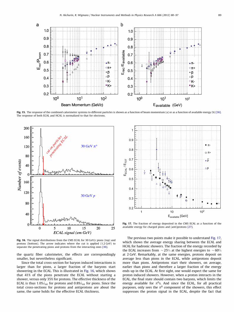
Fig. 16. The signal distributions from the CMS ECAL for 30 GeV/c pions (top) and
protons (bottom). The arrow indicates where the cut is applied (1.2 GeV) to
separate the penetrating pions and protons from the interacting ones [36].
Fig. 15. The response of the combined calorimeter systems to different particles is shown as a function of beam momentum (a) or as a function of available energy (b) [36].
The response of both ECAL and HCAL is normalized to that for electrons.
Eavailable [GeV]1 10 102
EE
CA
L / E
TOT
0.2
0.3
0.4
0.5
0.6
0.7
0.8
0.9
1
p
p
π-
π+
Fig. 17. The fraction of energy deposited in the CMS ECAL as a function of the
available energy for charged pions and (anti)protons [27].
N. Akchurin, R. Wigmans / Nuclear Instruments and Methods in Physics Research A 666 (2012) 80–97 89
the quartz fiber calorimeter, the effects are correspondinglysmaller, but nevertheless significant.
Since the total cross-section for baryon induced interactions islarger than for pions, a larger fraction of the baryons startshowering in the ECAL. This is illustrated in Fig. 16, which showsthat 41% of the pions penetrate the ECAL without starting ashower, versus only 35% for protons. The effective thickness of theECAL is thus 1:05lint for protons and 0:89lint for pions. Since thetotal cross-sections for protons and antiprotons are about thesame, the same holds for the effective ECAL thickness.
The previous two points make it possible to understand Fig. 17,which shows the average energy sharing between the ECAL andHCAL for hadronic showers. The fraction of the energy recorded bythe ECAL increases from � 25% at the highest energies to � 60%at 2 GeV. Remarkably, at the same energies, protons deposit onaverage less than pions in the ECAL, while antiprotons depositmore than pions. Antiprotons start their showers, on average,earlier than pions and therefore a larger fraction of the energyends up in the ECAL. At first sight, one would expect the same forproton induced showers. However, when a proton interacts in theECAL, the final state should contain two baryons, which limits theenergy available for p0s. And since the ECAL, for all practicalpurposes, only sees the p0 component of the showers, this effectsuppresses the proton signal in the ECAL, despite the fact that

N. Akchurin, R. Wigmans / Nuclear Instruments and Methods in Physics Research A 666 (2012) 80–9790
protons are more likely to start their showers in the ECALcompared to pions. The requirements of baryon number conserva-tion do not limit p0 production for antiproton induced showers. Infirst approximation, there is in this respect no difference with pioninduced showers. Therefore, the ECAL/HCAL energy sharing prop-erly reflects the difference in interaction length in this case.
The effects described above also explain why the antiprotonresponse is systematically smaller than the pion response(Fig. 15b). Antiprotons are more likely to start showering in theECAL compared to the pions. Pions deposit, on average a largerfraction of their energy in the HCAL. And since the e/h value of theHCAL is smaller than for the ECAL, the pions benefit more fromthe increased response to the non-em shower components.
In order to study the effects of the very different e/h values ofthe ECAL and HCAL, the pion event samples were grouped into‘‘early’’ and ‘‘late’’ starting showers. The distinction was made onthe basis of the energy fraction observed in the ECAL. For latestarting showers, this energy fraction was chosen such that eventsin the mip peak in the ECAL were selected. These pions thus onlylost some energy by ionization in the ECAL and underwent the firstnuclear interaction in the HCAL. In early starting events, the pionsdeposited a larger fraction of their energy in the ECAL. The pionresponse for these two classes of events is shown as a function ofavailable energy in Fig. 6, together with the overall pion response.For the lowest energies it was not possible to select a clean sampleof ‘‘late’’ events, since the mip peak was not clearly resolved in theECAL distribution (see Fig. 14a). Fig. 6 shows an increasingdiscrepancy between the calorimeter responses to early and lateshowers as the particle energy decreases. The discrepancy itselfreflects the different e/h values. Late showers deposit almost noenergy in the ECAL, and therefore their response is determined bythe (more compensating) HCAL. Early showers experience thestrong (by a factor 2.5) reduction in the response to the non-emshower component deposited in the ECAL. The fact that thediscrepancy increases at lower energy reflects the changes in thelongitudinal shower profile also observed in the energy sharingplot (Fig. 17). The larger the average fraction of the shower energydeposited in the ECAL, the larger the response discrepancybetween showers that start in the ECAL and those that do not.
CMS applies corrections to the signals from the considerablydifferent ECAL and HCAL in reconstructing the energies of hadrons asdescribed in detail in Ref. [36]. Above 5 GeV/c, these corrections leadto an energy resolution of the combined system where the stochasticterm equals 84.771.6% GeV�1/2 and the constant term is 7.470.8%.The corrected mean response remains constant within 1.3% rms.
At the lowest particle energies, the downward trend in thepion response is observed to reverse for early developing showers(see Fig. 6). The minimum response is observed at 4 GeV.A similar effect was observed by the ZEUS Collaboration [39],who also saw the response of their uranium/scintillator calori-meter increase for energies below 5 GeV. The explanation for thisphenomenon is the fact that at lower energies, a graduallyincreasing fraction of the particles range out without inducingany nuclear reaction. Nuclear reactions are responsible for theinvisible energy losses that increase e/h and thus reduce thehadronic response. The calorimeter responds to such non-inter-acting particles in the same way as it responds to muons. Below2 GeV, where almost all particles are completely stopped in thecalorimeter, the response is equal to that of electrons in the ECALand even larger than that (by a factor mip/e) in the HCAL.
3 http://geant4.cern.ch/support/proc_mod_catalog/physics_lists/physicsLists.
shtml4 This disagreement seems to be alleviated in V9.3 with physics list
FTFP_BERT.
6. Simulations
Hadronic shower simulations have been gradually improvingas a result of a better understanding of the underlying physics
processes and the availability of more powerful computingresources. One of the most common tools in this regard is GEANT4[40]. Several different physics lists3 that describe the variousphysics processes in shower development are now available forGEANT4 V9.2 (currently used in ATLAS and CMS) and V9.3. In thelast decade, an extensive validation program has been carried outfor the simulation of the LHC detectors [41]. We want to makesome general observations for GEANT4 V9.2 with the QGSP_BERTphysics list.
1.
The calorimeter response is a few percent larger than forexperimental data with an unphysical discontinuity between9.5 and 9.9 GeV due to a transition between two models forcharged pions (LEP and BERT models).2.
The simulated energy resolution is slightly (� 10%) betterthan in reality.3.
The longitudinal shower profile is also more compact (� 10%)compared to experimental data.4.
Laterally, the simulation results in showers that are � 15%narrower than in reality.5.
For protons, the discrepancy between the simulation andexperimental data seems worse than for pions, e.g. the simula-tion suggests a � 30% shorter shower profile.4Recently, a new physics list called CHIPS (Chiral InvariantPhase Space decay) [42–44] is being recommended by theGEANT4 developers. It gives reasonable shower shapes and asmooth response as a function of particle energy. It may poten-tially offer the best description of kaon, hyperon and anti-baryonhadronic interactions available in GEANT4. Fig. 18 shows acomparison between the predictions of the energy dependenceof a generic Cu/LAr calorimeter’s hadronic response. At lowenergies, the results vary by as much as 50%.
The data from ATLAS and CMS beam tests with the combinedem and hadronic calorimeters (thick-target) as well as stand-alone hadronic calorimeters have proven crucial for validation ofthe recent physics lists. Two different domains (thin- and thick-target) appear critical for further testing of hadronic showersimulations. Measurements of low energy hadronic interactionsin tracker detectors (thin-target) may prove useful to further tunethe inelastic hadronic cross-sections and final state models. Thisregion is typically the most difficult to simulate correctly. Hope-fully, the collision data from the LHC will shed further light andprovide useful input for simulations.
Other test material for hadronic shower simulations has beenprovided by the CALICE collaboration, which has been exploringcalorimeters with high granularity, intended for experimentsat a future linear collider. It might be possible to study detailsof the first interaction, correlations between longitudinal andlateral shower shapes and other features of the hadronic showersin these finely segmented systems. In Fig. 19, experimentallongitudinal shower profile data are compared with the predic-tions of various physics lists for 10 GeV p�s. The hadroniccalorimeter in this case consists of 3 cm thick steel platesinterleaved by small scintillator tiles of different sizes [45]. TheQGSP_BERT list seems to do the best job in describing theseexperimental data. The other lists either overestimate the energydensity at the shower maximum or underestimate the extend ofthe shower.

Fig. 18. The ratio of visible to beam energy as a function of the beam energy for
p�s showering in a simplified Cu/LAr calorimeter, as simulated in GEANT4
V9.3.p01 for different physics lists [41]. QGSP_BERT and LHEP show clear
discontinuities near 10 GeV, which seem to be absent in CHIPS.
Fig. 19. The longitudinal shower profile measurement with 10 GeV p�s is
contrasted against several physics lists. See Ref. [45] for details.
N. Akchurin, R. Wigmans / Nuclear Instruments and Methods in Physics Research A 666 (2012) 80–97 91
7. New developments in calorimetry
An often mentioned design criterion for calorimeters at afuture high-energy linear eþ e� collider is the need to distinguishbetween hadronically decaying W and Z bosons.5 The require-ment that the di-jet masses of W-qq and Z-qq events areseparable by at least one Rayleigh criterion implies that oneshould be able to detect 80–90 GeV jets with a resolution of3–3.5 GeV. This goal can be, and has been achieved with com-pensating calorimeters, as illustrated in Fig. 20 [46,47]. However,because of the small sampling fraction required for compensation,
5 An important reaction to be studied is eþ e�-H0Z0. By using the hadronic
decay modes of the Z0 (in addition to ‘þ ‘� decays), an important gain in event
rates can be obtained. However, more abundant processes such as eþ e�-W þW�
will obscure the signal unless the calorimeter is able to distinguish efficiently
between hadronic decay of W and Z bosons.
the em energy resolution is somewhat limited in such devices.Also, because of the crucial role of neutrons produced in theshower development, the signals would have to be integratedover relatively large volumes and time intervals to achieve thisresolution. This is not always possible in practice. In the follow-ing, we discuss some other methods that are currently beingpursued to circumvent these limitations.
7.1. Particle flow analysis
One method that has been proposed in this context, the so-called Particle Flow Analysis (PFA), is based on the combined use ofa precision tracker and a highly granular calorimeter. The idea isthat the charged jet particles can be precisely measured with thetracker, while the energy of the neutral particles is measured withthe calorimeter. Such methods have indeed successfully beenused to improve the mass resolution of hadronically decaying Z0sat LEP, to � 7 GeV=c2 [48]. Several detector concepts studied forthe ILC experimental program are based on this method aswell [49].
The problem that limits the success of this method is of coursethat the calorimeter does not know whether the particles itabsorbs are electrically charged. Therefore, one will have tocorrect the calorimeter signals for the contributions of thecharged jet particles. Proponents of this method have advocateda fine granularity as the key to the solution of this ‘‘double-counting’’ problem [16].
In order to increase the spatial separation between showersinduced by the various jet particles, and thus alleviate the double-counting problem, all concept detectors for the ILC that are basedon the PFA principle count on strong solenoidal magnetic fields(4–5 T). Such fields may indeed improve the validity of PFAalgorithms, especially at large distances from the vertex, sincethey open up a collimated beam of particles. After having traveleda typical distance of one meter in a 4 T magnetic field, thetrajectory of a 10 GeV pion deviates 6 cm from that of a straightline, i.e. less than one third of a nuclear interaction length intypical calorimeters. The field is also not always beneficial, since itmay have the effect of bending some jet particles with a relativelylarge transverse momentum with respect to jet axis into thejet core.
In the absence of reliable Monte Carlo simulations for hadronicshower development [50], the only way to prove or disprove theadvocated merits of the proposed PFA methods is by means ofdedicated experiments in realistic prototype studies.
The CALICE collaboration has set out to test the viability ofthese ideas. They have constructed a large calorimeter system,containing about 14,000 readout channels. For the electromag-netic section, silicon pads are used, while the hadronic section isequipped with plastic scintillator tiles or resistive plate chambers.The em section uses tungsten as absorber material, which limitsthe radial size of em showers. Iron, the absorber material used inthe hadronic section, has a Moliere radius that is twice that oftungsten, and a radiation length that is five times larger. Thismeans that the detector volume occupied by an em showercomponent differs by a factor of 20 in these two sections. Thiscalorimeter has been tested extensively since 2005 in testbeamsof electrons, muons and pions.
Technical aspects are elaborated in Refs. [17,51]. A detaileddiscussion on the performance of the instrument is yet to bepublished. Fig. 21 shows an event display of a hadronic showerdeveloping in the em/had calorimeter structure. Several single-track elements can be recognized and such track elements wereused for the mip calibration of this instrument. The figure alsoshows the hadronic energy resolution that was achieved on thebasis of such a calibration. Around 80 GeV, the energy at which

Fig. 21. Event display of a hadron shower in the CALICE calorimeter with identified track segments used for in situ mip calibration (left). Hadron energy resolution of the
CALICE calorimeter obtained with mip calibration from the same and from a different test beam site, transported with in situ methods (right) [51].
Fig. 20. Signal distributions for pions of 10, 40 and 150 GeV measured with the compensating Pb/plastic-scintillator SPACAL calorimeter [46].
N. Akchurin, R. Wigmans / Nuclear Instruments and Methods in Physics Research A 666 (2012) 80–9792
the crucial hadronic W/Z separation has to be performed, themeasured resolution is about 9%, i.e. more than a factor of twolarger than needed.
As indicated in Section 4, calibration is a crucial task in acalorimeter system of this type. The mip calibration used forobtaining the results from Fig. 21 is a good starting point.However, the real issue is of course how to translate these datainto particle, energy and position dependent numbers needed fordetermining the energy of showers developing in this structure.Given the complications described in Section 4.2, this will be adaunting task.
But even if this was successfully accomplished, one would stillbe faced with an even more challenging problem, namely how toavoid double counting, i.e. how to eliminate from the measuredcalorimetric energy deposit pattern the contributions fromcharged hadrons, whose momenta have been measured by thetracking system. There is no such thing as a ‘‘typical hadronicshower profile’’ that could be used for this purpose. This may beconcluded from detailed measurements of the energy depositprofiles in a finely segmented lead/iron/plastic-scintillator calori-meter [13]. Fig. 22 shows the longitudinal profiles of 12 randomlyselected events. The peaks in these profiles, which characterizethe large event-to-event differences, are caused by em showercomponents. The figure demonstrates that such components areabundantly produced beyond the first nuclear interaction length,i.e. in the hadronic section of typical calorimeter systems. Thisfeature is also the origin of calibration problems in segmentednon-compensating calorimeters (see Section 4). Even more pro-blematic for PFA purposes are the fluctuations in the planeperpendicular to the shower axis. These are similarly diverse. Itis possible that a very fine calorimeter segmentation could helpidentifying the precise energy deposit patterns of individualshowers developed by the charged jet fragments. However, thishas yet to be proven in practice.
One of the concept ILC detectors that plan to use Particle FlowAnalysis (GLD, one of the four concept detectors proposed for theILC) does not rely entirely on the advocated PFA merits, but haschosen a compensating lead/plastic-scintillator hadronic calori-meter section. Measurements of hadronic showers developing inprototypes of this detector gave a resolution of � 4:5 GeV in themost relevant 80–90 GeV region [52], in good agreement withearlier measurements for a similar structure [47].
7.2. Dual-readout calorimetry
A completely different approach is followed by the DREAMCollaboration, which tries to meet the mentioned performancerequirements by developing a calorimeter that can measure thejet energy sufficiently precisely by itself, i.e. without momentuminformation from the tracking system. Since the resolution isdetermined by fluctuations, eliminating or reducing the (effects ofthe) dominant fluctuations is the key to improving it.
In non-compensating calorimeters, the hadronic energy reso-lution is dominated by fluctuations in f em. The mentioned effectsof non-compensation on resolution, linearity and line shape, aswell as the associated calibration problems are absent in com-pensating calorimeters (e=h¼ 1:0). Compensation can be achievedin sampling calorimeters with high-Z absorber material andhydrogenous active material. It requires a very specific samplingfraction, so that the response to shower neutrons is boosted bythe precise factor needed to equalize e and h. For example, inPb/scintillating-plastic structures, this sampling fraction is � 2%for showers [46,53,54]. This small sampling fraction sets a lowerlimit on the contribution of sampling fluctuations, while the needto efficiently detect MeV-type neutrons requires signal integra-tion over a relatively large volume during at least 30 ns. Yet,calorimeters of this type currently hold the world record forhadronic energy resolution (s=E� 30%=
ffiffiffiEp
[46]).

Fig. 23. Cherenkov signal distribution for 100 GeV p� (a) and distributions for subsamples of events selected on the basis of the measured f em value (b). Signal
distributions for high-multiplicity 200 GeV ‘‘jets’’ in the DREAM calorimeter before (c) and after (d) corrections as described in the text were applied. In diagram (e), energy
constraints were used, which eliminated the effects of lateral shower leakage fluctuations that dominate the resolution in (d).
Fig. 22. Longitudinal energy deposit profiles for 270 GeV p� showers in a lead/iron/plastic-scintillator calorimeter [13]. Shown are the longitudinal profiles for 12
randomly chosen events. For each event, the horizontal scale spans a total depth of six nuclear interaction lengths.
N. Akchurin, R. Wigmans / Nuclear Instruments and Methods in Physics Research A 666 (2012) 80–97 93
The dual-readout approach aims to achieve the advantagesof compensation without these disadvantages. The energy carriedby the non-em shower component is mostly deposited bynon-relativistic shower particles (protons), and therefore doesnot contribute to the signals of a Cherenkov calorimeter. Bymeasuring simultaneously dE=dx and the Cherenkov light gener-ated in the shower absorption process, one can determine f em
event by event and thus eliminate (the effects of) its fluctuations.The correct hadron energy can be determined from a combinationof both signals.
This principle was first experimentally demonstrated by theDREAM Collaboration [55], with a Cu/fiber calorimeter. Scintillat-ing fibers measured dE=dx, quartz fibers the Cherenkov light. Theresponse ratio of these two signals, Q from clear and S from
scintillating fibers, is related to f em as
Q
S¼
f emþ0:21ð1�f emÞ
f emþ0:77ð1�f emÞð5Þ
where 0.21 and 0.77 represent the h/e ratios of the Cherenkov andscintillator calorimeter structures, respectively. The hadronenergy can be derived directly from the two signals:
E¼w� ðS�Q Þ
w�1, with w¼
½1�ðh=eÞQ �
½1�ðh=eÞS�¼ 3:43 ð6Þ
The merits of this method are illustrated in Fig. 23, whichshows that the energy resolution improved, the signal distribu-tion became much more Gaussian and, most importantly, the

Fig. 24. The time structure of a typical shower signal measured in the BGO
calorimeter equipped with a UV filter. These signals were measured with a
sampling oscilloscope, which took a sample every 0.8 ns. The signals were used
to measure the relative contributions of scintillation light (gate 2) and Cherenkov
light (gate 1) [58].
N. Akchurin, R. Wigmans / Nuclear Instruments and Methods in Physics Research A 666 (2012) 80–9794
hadronic energy was correctly reproduced in this way. This wastrue both for single pions and for multiparticle ‘‘jets.’’
It was shown that similar results can also be obtained withhigh-Z crystal calorimeters (PbWO4, BGO), whose signals can beseparated into scintillation and Cherenkov components [56–58].This was achieved by making use of differences between the timestructure and the photon spectra of both signal components.
Fig. 24 shows the time structure of BGO signals recorded witha UV filter. The ‘‘prompt’’ component observed in the ultravioletsignal is due to Cherenkov light. A small fraction of the scintilla-tion light also passes through the UV filter, and is responsible forthe tail in the time structure. This offers the possibility to obtainall needed information from that one signal. An external triggeropens two gates: one narrow (16 ns) gate covers the promptcomponent, the second gate (delayed by 30 ns and 65 ns wide)only contains scintillation light. The latter signal can also be usedto determine the contribution of scintillation to the light collectedin the narrow gate. In this way, the Cherenkov/scintillation ratiocan be measured event-by-event on the basis of one signal only.
Detailed measurements of the time structure of the signalsalso make it possible to clear another important hurdle towardultimate performance of hadron calorimeters, i.e. fluctuations inthe energy fraction used to break up atomic nuclei.6 It has beendemonstrated that the kinetic energy carried by the neutronsproduced in the shower development process is correlated to thisinvisible energy loss [2]. Efficient neutron detection, a keyingredient for compensating calorimeters, not only brings e/h to1.0, but also greatly reduces the contribution of fluctuations ininvisible energy to the hadronic energy resolution. It has beendemonstrated that this reduces the ultimate limit on this resolu-tion to � 13%=
ffiffiffiEp
[60], in compensating lead/plastic-scintillatorcalorimeters. This would translate into mass resolutions of� 1:5% for hadronically decaying W and Z bosons.
6 The elimination of fluctuations in f em takes care of the effects of the average
contribution of invisible energy. However, for a given value of f em, the invisible
energy fluctuates around this average.
Fig. 25 shows the average time structure of Cherenkov andscintillator signals measured for 100 GeV pþ showers developingin the DREAM fiber calorimeter. The scintillator signals exhibit anexponential tail with a time constant of � 20 ns. This tail has allthe characteristics expected of a (nonrelativistic) neutron signaland is thus absent in the time structure of the Cherenkov signals.Event-by-event analysis of the contribution of neutrons to thecalorimeter signals showed that this contribution is anti-corre-lated to f em, and makes it possible to further improve the energyresolution beyond the levels made possible by the dual-readoutmethod [61].
7.3. Challenges
Many years of experience have shown that detectors based onlight as the source of experimental information have their owncharacteristic problems. Among these, we mention the effects oflight attenuation, short-term instabilities arising from tempera-ture and other environmental effects, and long-term effects ofradiation damage and other aging phenomena. Perhaps the mostdaunting challenges should be expected from light attenuation.The scale for fluctuations in hadronic shower development is setby the nuclear interaction length, typically � 20 cm in realisticdetector structures. A typical characteristic of a dual-readoutcalorimeter is its longitudinally unsegmented structure, chosendeliberately to avoid the problems discussed in Section 4. If onewants to limit the effects of spatial shower fluctuations on thesignals in such an unsegmented calorimeter to 1%, then the lightattenuation length of the readout elements thus has to be� 20 m.7 This requirement will be extremely hard to achievewith active media other than optical fibers. On the other hand, itmay be very hard to make a 4p detector structure with long-itudinal optical fibers.
A second set of problems for light-based calorimeters arisesfrom the need to operate in a magnetic field. Not only does thisfield affect the light production characteristics of some media, italso limits the choice of light detectors. New types of lightdetectors developed to deal with these problems (HPD, APD,SiPM) exhibit encouraging, but by no means ideal characteristics.
8. Non-accelerator applications of hadron calorimetry
All calorimeters discussed in the previous sections were man-made. In this section, we look into efforts to use our naturalenvironment as a calorimeter. The driving force behind theseefforts is the opportunity to create a very large instrument in thisway. Typical detector volumes are measured in units of km3, i.e. atleast four orders of magnitude larger than SuperKamiokande [63],which has one of the largest instrumented volumes of any man-made calorimeter. Such large volumes are needed to achieve thescientific goals of the experiments, which usually focus on thestudy of very rare natural phenomena. Examples of such phe-nomena include the absorption of extremely high-energy protons,as or heavier atomic nuclei of extraterrestrial origin in the Earth’satmosphere and interactions of extra-galactic neutrinos in theEarth itself.
Almost all natural calorimeters are based on light as the sourceof experimental information. In one noteworthy exception, radiosignals are exploited. Usually, the Cherenkov mechanism is thesource of the signals, especially in detectors where sea water or
7 This number applies to single hadrons. The requirements are much less
stringent for the detection of jets, since the depth fluctuations in light production
decrease considerably for a number of particles that simultaneously develop
showers in the same structure [62,55].

Fig. 25. The average time structure of the Cherenkov (a) and scintillator (b) signals measured for 100 GeV pþ showers in a tower located on the shower axis. The shown
PMT signals have been inverted to positive for convenience. The lines represent exponential fits to (parts of) the trailing edge of the signal shapes [59] (see text for details).
Fig. 26. One of the Digital Optical Modules used in the IceCube experiment. Shown are a schematic drawing of this module (left), the real thing assembled (center) and
being lowered to its final position in the ice (right).
N. Akchurin, R. Wigmans / Nuclear Instruments and Methods in Physics Research A 666 (2012) 80–97 95
Arctic ice serve as the absorber medium. Cherenkov light isusually also an important source of experimental information indetectors using the Earth’s atmosphere as a calorimeter. In someexperiments of the latter type, scintillation light is used as well.
The technique to measure the Cherenkov light produced byextremely high-energy neutrinos of cosmic origin in water waspioneered in Lake Baikal (Siberia) by a consortium of Russian andGerman scientists [64]. A telescope consisting of a lattice of 200large PMTs spread over a large open volume at a depth of � 1 kmlooks for upward traveling muons produced in neutrino interac-tions in water in the vicinity of the detector. Since the anglebetween the parent neutrino and the muon produced in theinteraction is very small, high-resolution astronomy is in princi-ple possible. The direction of the particle can be inferred from themeasured arrival times and amplitudes of the Cherenkov photonsobserved in the various PMTs. The same technique is applied, on amuch larger scale, in the Antarctic ice near the Amundsen-ScottSouth Pole station. The IceCube experiment [65,66] has currentlyinstalled 4740 PMTs covering a volume of � 1 km3 at a depthranging from 1450 to 2450 m below the surface (Fig. 26).
Another structure of similar dimensions is planned for instal-lation somewhere in the Mediterranean. Exploratory work in that
context has been carried out by the ANTARES [67], NEMO [68]and NESTOR [69] Collaborations. Some advantages of ice overwater in a lake or sea include the absence of light emittingorganisms and underwater currents that may jeopardize theintegrity of the detector structure. On the other hand, lightscattering by air bubbles trapped in ice may limit the possibilitiesto reconstruct the direction of the incoming particles.
The operation of detectors of this type is of course verydifferent from those in accelerator laboratories. Whereas muonsare usually referred to as ‘‘minimum ionizing particles’’ (mips) inaccelerator based experiments, IceCube uses the non-mip natureof these particles to calibrate the energy scale of their detector,exploiting the fact that the specific energy loss (dE=dx) dependslogarithmically on the muon energy in the region of interest(TeV–EeV). The angular resolution of their instrument (o0:51) ismeasured using the shadow of the Moon, which measurablyaffects the rate of down-going atmospheric muons. With thiskind of resolution one might hope to detect point sources ofextraterrestrial neutrinos.
The Antarctic ice cap is also the source of signals for the ANITAexperiment [70], which aims to detect the radio component of thecoherent Cherenkov signals produced as a result of the charge

Fig. 27. One of the Cherenkov telescopes used in the HEGRA experiment at La
Palma. Photo courtesy K. Bernlohr.
N. Akchurin, R. Wigmans / Nuclear Instruments and Methods in Physics Research A 666 (2012) 80–9796
asymmetry in high-energy em showers, the so-called Askaryaneffect [71]. This mechanism may also be exploited in other mediathat are transparent to such radio signals, for example large rocksalt formations [72].
Experiments using the Earth’s atmosphere as a calorimeter areprimarily looking for extensive air showers caused by very-high-energy charged cosmic particles. At sea level, the atmosphererepresents an absorber with a total thickness of � 11lint, or� 28X0, enough to absorb even the highest energy particles to avery large extent. The Cherenkov light produced in the absorptionprocess is relatively easy to detect, provided that it is emitted inthe direction of the telescope that is looking for it (Fig. 27).Because of the very small refraction index of air, the Cherenkovangle is very small and only energetic shower particles producedin the early stages of the shower development emit Cherenkovlight. As a result, this light is highly collimated, a shower startingat the typical altitude of 10 km produces a light cone at groundlevel with a radius of only � 100 m. Therefore, modern experi-ments looking for hadronic showers complement the Cherenkovtelescopes with additional detectors, looking for (isotropicallyemitted) fluorescent light (produced by transitions in molecularnitrogen and in Nþ2 ions), for muons from decaying showerparticles (p,K), and/or shower particles themselves. Examples ofsuch experiments include AUGER [73] and KASKADE-Grande [74](hadronic showers) and VERITAS [75] and HESS [76] (emshowers). The angular resolutions of these experiments are evenbetter than those obtained with IceCube. Apart from the shadow-ing effect of the Moon [77], one can also use the signals fromsome known point sources of g rays for this purpose. The signalsfrom the strongest of these sources, the Crab nebula, is also avaluable tool for the energy calibration. Variations of the order of20% between the different experiments that use this technique[78] are indicative for the relative uncertainty in the energy scale.More information about this exciting field and the role played byhadron calorimeters in advancing it can be found in Ref. [79].
9. Summary
We would like to finish this review with some concludingremarks that we expect will serve the developers of futuredetectors, as well as users of present ones.
�
If a dedicated hadron calorimeter is equipped with a separate emsection that has the purpose to measure em showers with betterprecision, then the hadronic energy resolution of the combinedsystem is worse than that of the hadronic section alone,especially at high energies. In cases like ATLAS and CMS, theperformance of the combined calorimeters is what matters.
� Longitudinal segmentation of a calorimeter system greatlycomplicates the calibration of the calorimeter system, andmay in fact make a correct calibration impossible in practice.
� Positioning readout elements inside the absorber structure(between the em and hadronic sections, for example) shouldbe avoided because this introduces spurious signals due tointeractions in the photosensors. The hadronic shower max-imum takes place roughly after one interaction length, com-parable with the depth of typical em sections.
� Energy resolution is determined by event-to-event fluctua-tions, not by average values. This means that attempts toimprove the energy resolution of a longitudinally segmentedcalorimeter by applying different global weight factors tosignals from different segments are not meaningful. For thesame reason, the presumed advantage of Particle Flow Analy-sis is doubtful. If only the charged jet fragments were mea-sured, the jet energy resolution would not be better than� 20%, at any energy [80]. ffiffiffip
� Quoting hadronic energy resolutions in terms of x%= E istypically not very meaningful. Especially when the instrumentis intended for measurements at high energies, its resolutiontends to be dominated by deviations from E�1=2 scaling. Inaddition, statements about energy resolution are only mean-ingful if they include the effects of non-linearity, which applyto almost all calorimeter systems currently in use or planned.Signal non-linearity introduces additional uncertainties in themean value of the response function for jets, which have to betaken into account if one wants to address the precision withwhich the energy of individual jets can be measured.
� Monte Carlo simulations have been improving both in physicscontent and in precision over the last decade, but the ultimatetruth lies in experimental data, often obtained in well exe-cuted beam tests.
References
[1] R. Brown, D. Cockerill, Nuclear Instrumentation and Methods in PhysicsResearch Section A, doi:10.1016/j.nima.2011.03.017, this issue.
[2] R. Wigmans, Calorimetry: Energy measurement in particle physics, in:International Series of Monographs on Physics, vol. 107, 2000, pp. 1–726.
[3] D. Green, Cambridge Monographs on Particle Physics, Nuclear Physics andCosmology 12 (2000) 1.
[4] C. Grupen, B. Schwartz, Particle Detectors, Cambridge University Press,Cambridge, UK, 2008, p. 651.
[5] C. Leroy, P.-G. Rancoita, Principles Of Radiation Interaction in Matter andDetection, ISBN-13-9789812389091.
[6] C.W. Fabjan, F. Gianotti, Reviews of Modern Physics 75 (2003) 1243.doi:10.1103/RevModPhys.75.1243.
[7] C. Amsler, et al., Physics Letters B 667 (2008) 1. doi:10.1016/j.physletb.2008.07.018.
[8] M.G. Albrow, et al., Nuclear Instrumentation and Methods in PhysicsResearch Section A 431 (1999) 104. doi:10.1016/S0168-9002(99)00250-8.
[9] D. Acosta, et al., Nuclear Instrumentation and Methods in Physics ResearchSection A 302 (1991) 36. doi:10.1016/0168-9002(91)90489-D.
[10] H. Abramowicz, et al., Nuclear Instrumentation and Methods in PhysicsResearch Section A 180 (1981) 429. doi:10.1016/0029-554X(81)90083-5.
[11] P. Adragna, et al., Nuclear Instrumentation and Methods in Physics ResearchSection A 606 (2009) 362. doi:10.1016/j.nima.2009.04.009.
[12] P. Adragna, et al., Nuclear Instrumentation and Methods in Physics ResearchSection A 615 (2010) 158. doi:10.1016/j.nima.2010.01.037.
[13] D. Green, Selected topics in sampling calorimetry, Prepared for 4th Interna-tional Conference on Calorimetry in High-energy Physics, La Biodola, Italy,19–25 September 1993.
[14] M.G. Albrow, et al., Nuclear Instrumentation and Methods in PhysicsResearch Section A 487 (2002) 381. doi:10.1016/S0168-9002(01)02190-8.
[15] R. Wigmans, AIP Conference Proceeding 867 (2006) 90. doi:10.1063/1.2396942.
[16] TESLA Technical Design Report, Report DESY 2001-011.

N. Akchurin, R. Wigmans / Nuclear Instruments and Methods in Physics Research A 666 (2012) 80–97 97
[17] C. Adloff, et al., CALICE Report to the Calorimeter R&D Review Panel,arxiv:0707.1245.
[18] D. Acosta, et al., Nuclear Instrumentation and Methods in Physics ResearchSection A 316 (1992) 184. doi:10.1016/0168-9002(92)90901-F.
[19] N. Akchurin, et al., Nuclear Instrumentation and Methods in Physics ResearchSection A 399 (1997) 202. doi:10.1016/S0168-9002(97)00789-4.
[20] T. Gabriel, et al., Nuclear Instrumentation and Methods in Physics ResearchSection A 338 (1994) 336.
[21] N. Akchurin, et al., Nuclear Instrumentation and Methods in Physics ResearchSection A 408 (1998) 380. doi:10.1016/S0168-9002(98)00021-7.
[22] J.B. Birks, The Theory and practice of scintillation counting, in: Internationalseries of Monographs on Electronics and Instrumentation, vol. 27, Macmillan,New York.
[23] I. Galaktionov, et al., Nuclear Instrumentation and Methods in PhysicsResearch Section A 251 (1986) 258. doi:10.1016/0168-9002(86)90790-4.
[24] S. Cihangir, F. Marchetto, P. McIntyre, T. Meyer, R. Webb, Nuclear Instru-mentation and Methods in Physics Research Section A 267 (1988) 249.doi:10.1016/0168-9002(88)90472-X.
[25] S. Cihangir, et al., IEEE Transactions on Nuclear Science NS-36 (1989) 347.doi:10.1109/23.34462.
[26] D.E. Groom, Nuclear Instruments and Methods in Physics Research Section A:Accelerators, Spectrometers, Detectors and Associated Equipment 572 (2)(2007) 633. doi:10.1016/j.nima.2006.11.070.
[27] N. Akchurin, et al., The response of CMS combined calorimeters to singlehadrons, electrons and muons, CERN-CMS-NOTE-2007-012.
[28] O. Ganel, R. Wigmans, Nuclear Instrumentation and Methods in PhysicsResearch Section A 409 (1998) 621. doi:10.1016/S0168-9002(97)01337-5.
[29] F. Cervelli, et al., Nuclear Instrumentation and Methods in Physics ResearchSection A 490 (2002) 132. doi:10.1016/S0168-9002(02)00915-4.
[30] T. Akesson, et al., Nuclear Instrumentation and Methods in Physics ResearchSection A 262 (1987) 243. doi:10.1016/0168-9002(87)90862-X.
[31] R. Wigmans, M.T. Zeyrek, Nuclear Instrumentation and Methods in PhysicsResearch Section A 485 (2002) 385. doi:10.1016/S0168-9002(01)02141-6.
[32] M. Aharrouche, et al., Nuclear Instrumentation and Methods in PhysicsResearch Section A 568 (2006) 601. doi:10.1016/j.nima.2006.07.053 arxiv:physics/0608012.
[33] ATLAS-Collaboration, ATLAS Tile calorimeter: Technical Design Report, CERN-LHCC-96-42, 1996, p. 347.
[34] E. Abat, et al., Nuclear Instrumentation and Methods in Physics ResearchSection A 607 (2009) 372. doi:10.1016/j.nima.2009.05.158.
[35] E. Abat, et al., Nuclear Instrumentation and Methods in Physics ResearchSection A 621 (2010) 134. doi:10.1016/j.nima.2010.04.054.
[36] S. Abdullin, et al., European Physical Journal C 60 (2009) 359. doi:10.1140/epjc/s10052-009-0959-5.
[37] S. Abdullin, et al., European Physical Journal C 55 (2008) 159. doi:10.1140/epjc/s10052-008-0573-y.
[38] S. Abdullin, et al., European Physical Journal C 57 (2008) 653. doi:10.1140/epjc/s10052-008-0756-6.
[39] A. Andresen, et al., Nuclear Instrumentation and Methods in Physics ResearchSection A 290 (1990) 95. doi:10.1016/0168-9002(90)90347-9.
[40] S. Agostinelli, et al., Nuclear Instrumentation and Methods in PhysicsResearch Section A 506 (2003) 250. doi:10.1016/S0168-9002(03)01368-8.
[41] A. Ribon, et al., Status of GEANT4 Hadronic Physics for the Simulation of LHCExperiments at the Start of LHC Physics Program, CERN-LCGAPP-2010-02.
[42] P.V. Degtyarenko, M.V. Kosov, H.P. Wellisch, European Physical Journal A 8(2000) 217. doi:10.1007/s100500070108.
[43] P.V. Degtyarenko, M.V. Kossov, H.P. Wellisch, European Physical Journal A 9(2000) 411. doi:10.1007/s100500070025.
[44] P.V. Degtyarenko, M.V. Kossov, H.P. Wellisch, European Physical Journal A 9(2000) 421. doi:10.1007/s100500070026.
[45] K. Seidel, et al., Particle Showers in a Highly Granular Hadron Calorimeterarxiv:1004.2587v1.
[46] D. Acosta, et al., Nuclear Instrumentation and Methods in Physics ResearchSection A 308 (1991) 481. doi:10.1016/0168-9002(91)90062-U.
[47] U. Behrens, et al., Nuclear Instrumentation and Methods in Physics ResearchSection A 289 (1990) 115. doi:10.1016/0168-9002(90)90253-3.
[48] D. Buskulic, et al., Nuclear Instrumentation and Methods in Physics ResearchSection A 360 (1995) 481. doi:10.1016/0168-9002(95)00138-7.
[49] /http://physics.uoregon.edu/� lc/wwstudy/concepts/S.[50] M. Albrow, R. Raja, (Eds.), Hadronic shower simulation, in: Proceedings,
Workshop, Batavia, USA, September 6–8, 2006, Prepared for HadronicShower Simulations Workshop, Batavia, Illinois, 6–8 September 2006.
[51] Report to the DESY PRC arxiv:1003.1394v1.[52] S. Uozumi, et al., Nuclear Instrumentation and Methods in Physics Research
Section A 487 (2002) 291. doi:10.1016/S0168-9002(01)00891-9.[53] E. Bernardi, et al., Nuclear Instrumentation and Methods in Physics Research
Section A 262 (1987) 229. doi:10.1016/0168-9002(87)90861-8.[54] T. Suzuki, et al., Nuclear Instrumentation and Methods in Physics Research
Section A 432 (1999) 48. doi:10.1016/S0168-9002(99)00394-0.[55] N. Akchurin, et al., Nuclear Instrumentation and Methods in Physics Research
Section A 537 (2005) 537. doi:10.1016/j.nima.2004.07.285.[56] N. Akchurin, et al., Nuclear Instrumentation and Methods in Physics Research
Section A 595 (2008) 359. doi:10.1016/j.nima.2008.07.136.[57] N. Akchurin, et al., Nuclear Instrumentation and Methods in Physics Research
Section A 584 (2008) 273. doi:10.1016/j.nima.2007.09.035 arxiv:0707.4021.[58] N. Akchurin, et al., Nuclear Instrumentation and Methods in Physics Research
Section A 598 (2009) 710. doi:10.1016/j.nima.2008.10.010.[59] N. Akchurin, et al., Nuclear Instrumentation and Methods in Physics Research
Section A 581 (2007) 643. doi:10.1016/j.nima.2007.08.049 arxiv:0707.4019.[60] G. Drews, et al., Nuclear Instrumentation and Methods in Physics Research
Section A 290 (1990) 335. doi:10.1016/0168-9002(90)90549-L.[61] N. Akchurin, et al., Nuclear Instrumentation and Methods in Physics Research
Section A 598 (2009) 422. doi:10.1016/j.nima.2008.09.045.[62] D. Acosta, et al., Nuclear Instrumentation and Methods in Physics Research
Section A 309 (1991) 143. doi:10.1016/0168-9002(91)90096-9.[63] S. Fukuda, et al., Nuclear Instrumentation and Methods in Physics Research
Section A 501 (2003) 418. doi:10.1016/S0168-9002(03)00425-X.[64] /http://baikalweb.jinr.ru/S.[65] S.R. Klein, IEEE Transactions on Nuclear Science NS-56 (2009) 1141.
doi:10.1109/TNS.2009.2015300 arxiv:0807.0034.[66] F. Halzen, S.R. Klein, Review of Scientific Instruments 81 (2010) 081101.
doi:10.1063/1.3480478 arxiv:1007.1247.[67] /http://antares.in2p3.fr/S.[68] /http://nemoweb.lns.infn.it/S.[69] /http://www.nestor.noa.gr/S.[70] /http://www.phys.hawaii.edu/anita/web/index.html/S.[71] G. Askaryan, Soviet Physics JETP 14 (1961) 441.[72] P. Gorham, et al., Nuclear Instrumentation and Methods in Physics Research
Section A 490 (2002) 476. doi:10.1016/S0168-9002(02)01077-X arxiv:hep-ex/0108027.
[73] /http://www.auger.org/S.[74] /http://www-ik.fzk.de/KASCADE/S.[75] /http://veritas.sao.arizona.edu/S.[76] /http://www.mpi-hd.mpg.de/hfm/HESS/S.[77] C.M. Hoffman, C. Sinnis, P. Fleury, M. Punch, Review in Modern Physics 71
(1999) 897. doi:10.1103/RevModPhys.71.897.[78] F.A. Aharonian, et al., Astrophysics Journal 539 (2000) 317. doi:10.1086/
309225 arxiv:astro-ph/0003182.[79] R. Clay, B.R. Dawson, Cosmic Bullets: High Energy Particles in Astrophysics,
Allen and Unwin, St Leonards, N.S.W., 1997.[80] O. Lobban, A. Sriharan, R. Wigmans, Nuclear Instrumentation and Methods
in Physics Research Section A 495 (2002) 107. doi:10.1016/S0168-9002(02)01615-7.