Review Fabrication of Functionally Graded Materials under a
20
7 Review Fabrication of Functionally Graded Materials under a Centrifugal Force Yoshimi Watanabe and Hisashi Sato Nagoya Institute of Technology Japan 1. Introduction The formation of gradients of chemical composition, phase distribution or microstructure represents a now fervently pursued concept in the design of advanced engineering components. In light of this concept, a significant progress has been made in the area of functionally graded materials (FGMs). FGMs are of practical interest because a wide gradation of physical and/or chemical properties can be achieved across a given material depending on the material design (Suresh & Mortensen, 1998, Miyamoto et al., 1999, Uemura et al., 2010). Thus, FGM holds continuous changes of the microstructure, the composition and the properties in some specific directions, i.e., inhomogeneous on both macroscopic and microscopic scales. On the other hand, particle-, fibre- or platelet-dispersed composites are regarded as macroscopically homogeneous and microscopically inhomogeneous. There are two types of graded structures of the FGMs, namely continuous structure shown in Fig. 1 (a), and stepwise structure shown in Fig. 1 (b). In the first type, the change in composition and/or microstructure occurs continuously with position. On the other hand in the second type, the microstructure feature changes in a stepwise manner, giving rise to a multilayered structure with interfaces existing between discrete layers (Miyamoto et al., 1999). As will be described in more detail below, the continuous graded structure can be created by a centrifugal force. Fig. 1. Two types of graded structures. (a) Continuous structure, and (b) stepwise structure. In the past, many kinds of processing methods for FGM have been proposed (Suresh & Mortensen, 1998, Miyamoto et al., 1999, Uemura et al., 2010). Powder metallurgy is one of www.intechopen.com
Transcript of Review Fabrication of Functionally Graded Materials under a
7
Review Fabrication of Functionally Graded Materials under a Centrifugal Force
Yoshimi Watanabe and Hisashi Sato Nagoya Institute of Technology
Japan
1. Introduction
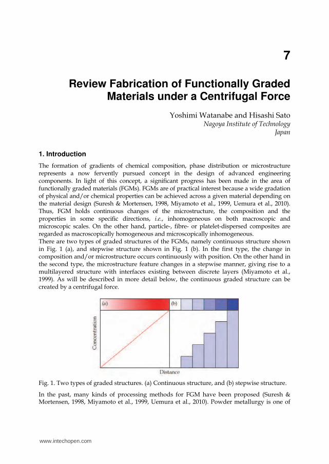
The formation of gradients of chemical composition, phase distribution or microstructure represents a now fervently pursued concept in the design of advanced engineering components. In light of this concept, a significant progress has been made in the area of functionally graded materials (FGMs). FGMs are of practical interest because a wide gradation of physical and/or chemical properties can be achieved across a given material depending on the material design (Suresh & Mortensen, 1998, Miyamoto et al., 1999, Uemura et al., 2010). Thus, FGM holds continuous changes of the microstructure, the composition and the properties in some specific directions, i.e., inhomogeneous on both macroscopic and microscopic scales. On the other hand, particle-, fibre- or platelet-dispersed composites are regarded as macroscopically homogeneous and microscopically inhomogeneous. There are two types of graded structures of the FGMs, namely continuous structure shown in Fig. 1 (a), and stepwise structure shown in Fig. 1 (b). In the first type, the change in composition and/or microstructure occurs continuously with position. On the other hand in the second type, the microstructure feature changes in a stepwise manner, giving rise to a multilayered structure with interfaces existing between discrete layers (Miyamoto et al., 1999). As will be described in more detail below, the continuous graded structure can be created by a centrifugal force.
Fig. 1. Two types of graded structures. (a) Continuous structure, and (b) stepwise structure.
In the past, many kinds of processing methods for FGM have been proposed (Suresh & Mortensen, 1998, Miyamoto et al., 1999, Uemura et al., 2010). Powder metallurgy is one of
www.intechopen.com

Nanocomposites with Unique Properties and Applications in Medicine and Industry 134
the most important methods of producing FGMs. An example of a typical fabrication process by the powder metallurgy is schematically illustrated in Fig. 2. At first, material A and material B are weighed and mixed, as shown in Fig. 2 (a). The each mixed-powder is mixed uniformly by a V-shape mill, as shown in Fig. 2 (b). Next step is stepwise staking of premixed powder according to a predesigned spatial distribution of the composition (Fig. 2 (c)). Last step is a sintering. Spark plasma sintering (SPS), shown in Fig. 2 (d), is one of the more advanced sintering methods, and it makes possible sintering high quality materials in short periods by charging the intervals between powder particles with electrical energy and high sintering pressure. However, usually the FGM fabricated by this method should have the stepwise structure, and it is difficult to produce the FGMs with continuous gradients.
Fig. 2. Example of typical fabrication process of the FGMs by powder metallurgy method.
FGMs can be also fabricated under a centrifugal force, by which it is possible to produce the FGMs with continuous gradients. Fabrication methods of FGMs under the centrifugal force are classified into three categories, as shown in Fig. 3, namely centrifugal method (application of centrifugal casting, and shown in Fig. 3 (a)), centrifugal slurry method (centrifugal sedimentation, and shown in Fig. 3 (b)) and centrifugal pressurization method (simple pressurization by the centrifugal force, and one example is shown in Fig. 3 (c)). In case of centrifugal method shown in Fig. 3 (a), a centrifugal force applied to a homogeneous molten metal, dispersed with ceramics particles or intermetallic compound particles, drives the formation of the desired gradation. The composition gradient is then achieved primarily by the difference in the centrifugal force produced by the difference in density between the molten metal and solid particles (Fukui, 1991, Watanabe et al., 1998). It is known that the motion of particles in a viscous liquid under a centrifugal force obeys the Stokes' law (Kang & Rohatgi, 1996, Watanabe et al., 1998, Ogawa et al., 2006)
18
- 2
pmp GgD
dt
dx (1)
www.intechopen.com

Review Fabrication of Functionally GradedMaterials under a Centrifugal Force 135
where dx/dt, , G, g, D and are velocity, density, G number (the ratio of the centrifugal
force to the gravity), gravitational acceleration, particle diameter and viscosity of the molten
metal, respectively. The subscripts 'p' and 'm' denote particle and matrix, respectively. When
the desired gradation is achieved, motion of solid particles will be stopped by solidification
of molten metal, and the solidified metal becomes a matrix of the FGM.
In contrast, slurry with two types of solid particles, high-velocity particle and low-velocity
particle, is subjected to the centrifugal force during the fabrication of FGMs by the
centrifugal slurry method (Watanabe et al., 2010), as shown in Fig. 3 (b). After complete
sedimentation occurs, liquid part of the slurry will be removed, and therefore, it does not
become a part of FGM.
Third one is the centrifugal pressurization method, by which the centrifugal force is only
used for simple pressurization. In this method, compositional gradation should be formed
prior the application of centrifugal force. Watanabe et al. are developing a centrifugal
mixed-powder method, shown in Fig. 3 (c) (Watanabe et al., 2009), and a reactive centrifugal
casting method (Watanabe et al., 2004a), which belong this category. In this chapter, some
results from the centrifugal method, centrifugal slurry method, centrifugal mixed-powder
method and reactive centrifugal casting method will be described.
Fig. 3. Three types of fabrication methods of FGMs under the centrifugal force. (a) centrifugal method, (b) centrifugal slurry method, and (c) centrifugal pressurization method (Watanabe et al., 2010).
2. Centrifugal method
Centrifugal casting is a pressure casting, in which the force of gravity is enhanced by
spinning the mould. Generally, the segregation, caused by the density-difference between
particles and molten metal, must be avoided. However, it is possible to create a
compositional gradient due to the difference in material density (Fukui, 1991, Watanabe et
al., 1998). Figure 4 shows the apparatus used for the centrifugal method. The ingot is melted and then
the plug is pulled out to cast the molten metal directly into the spinning mould through the
inlet. The spinning mould is preheated before the casting. The magnitude of the centrifugal
force is expressed in G number, which is the ratio of the centrifugal force to the gravity, g, as
given by the following equation:
G = 2DN2 (2)
www.intechopen.com

Nanocomposites with Unique Properties and Applications in Medicine and Industry 136
where D is the diameter of the cast ring (m) and N is the rotation speed of the mould (s-1). After casting, the mould-preheating furnace is removed and the mould is cooled until complete solidification occurs.
Fig. 4. The apparatus for the centrifugal method.
The composition gradient formed by the centrifugal method is affected by the difference in
density between particles and a molten metal, the applied G number, the particle size, the
viscosity of the melt, the mean volume fraction of particles, the thickness of manufactured
ring and the solidification time (Watanabe et al., 1998). It is obvious that both density and
viscosity are the materials’ constants and both the volume fraction and thickness are the
constants of products. Moreover, applied G number and solidification time show a mutual
relation. One of the easily changeable parameters for the control of graded composition is
the particle size.
2.1 Ceramic-particle dispersed FGMs fabricated by the centrifugal method
The typical microstructure of the Al/SiC FGM fabricated by the centrifugal method is
shown in Fig. 5 (Fukui & Watanabe, 1996), where the applied G number is 129. Figs. 5 (a)
and (b) are taken at different positions, namely they are 4.1 mm and 0.5 mm from outer
periphery of the ring, respectively. As can be seen, the amount of SiC particles changes from
place to place. The moving direction of the particle under the centrifugal force is determined
by the relative magnitudes of densities. Since the densities of SiC and molten Al at 700 oC
are 3.15 Mg/m3 and 2.37 Mg/m3, respectively, the SiC particles move toward the outer
periphery of the ring under the centrifugal force.
Figure 6 shows the histogram of the ceramic-particle volume fraction of the Al/SiC FGM
fabricated by the centrifugal method (Fukui & Watanabe, 1996). In this figure, the abscissa
represents the position in the thickness direction of the ring, normalized by the thickness,
i.e., 0.0 and 1.0 correspond to the inner and outer peripheries, respectively. It is clear that the
distributions of the particles in both specimens are graded, suggesting that the ceramic-
dispersed FGMs can successfully be fabricated by the centrifugal method.
www.intechopen.com

Review Fabrication of Functionally GradedMaterials under a Centrifugal Force 137
Fig. 5. Typical microstructure of the Al/SiC FGM fabricated by the centrifugal method (Fukui & Watanabe, 1996). Black and white are SiC and Al matrix, respectively.
Fig. 6. Distribution of the volume fraction of SiC particles in the FGM fabricated by the centrifugal method (Fukui & Watanabe, 1996).
Fig. 7. The particle distribution in the FGM fabricated by the centrifugal solid-particle method under G=15 (Watanabe et al., 2002).
www.intechopen.com

Nanocomposites with Unique Properties and Applications in Medicine and Industry 138
As described in introduction, the motion of ceramic particles in a viscous liquid under a centrifugal force can be estimated using Stokes' law. Therefore, in the FGMs fabricated by the centrifugal method, the mean particle size is distributed gradually along the applied centrifugal force. Figure 7 shows the particle distributions in the FGM fabricated by the centrifugal method (Watanabe et al., 2002). Note that the volume fraction of particles gradually increases towards the outer region. The most remarkable result shown in this figure is that the average particle size at the outer region is larger than that at the inner region, and the average particle size is gradually distributed in the FGMs. Although the data are not presented here, it has also been found that the particle size gradient in the FGM becomes steeper with increasing the G number or with decreasing the mean volume fraction of particles (Watanabe et al., 2002). These results are in agreement with the Stokes' law; the migration distance is greater for larger particles.
2.2 Intermetallic-particle dispersed FGMs fabricated by the centrifugal method Intermetallic compound particles could be also applicable for the centrifugal method as dispersed particles. The fabrication of the intermetallic compound particles dispersed FGMs by the centrifugal method can be classified into two categories based on the relation between the processing temperature and the liquidus temperature of master alloy (Watanabe et al., 2005). If the liquidus temperature of the master alloy is significantly higher than the processing temperature, as shown in Fig. 8 (a), the dispersed phase remains solid in a liquid matrix during the centrifugal casting. Alternatively, if the liquidus temperature of the master alloy is lower than the processing temperature, as shown in Fig. 8 (b), centrifugal force can be applied during the solidification both to the dispersed phase and to the matrix. These methods are referred to as a centrifugal solid-particle method and a centrifugal in-situ method, respectively (Watanabe et al., 2005).
2.2.1 Centrifugal solid-particle method Since the liquidus temperature of Al-5mass%Ti alloy, containing 11vol% Al3Ti platelets in the Al matrix, is about 1160 oC and the processing temperature is 840 oC of a liquid-solid coexisting temperature, the Al3Ti platelets remain solid in the liquid Al matrix and a centrifugal force is worked directly to platelets during the casting process. Figure 9 shows typical microstructures of an Al/Al3Ti FGM fabricated under G = 30 (Watanabe et al., 2001). It is found that the volume fraction of the Al3Ti platelets increases towards the outer region of the ring. The steeper distribution profile of the Al3Ti platelets is formed in case of larger applied G specimen. It is worthwhile to notice that the Al3Ti particles are oriented with their platelet planes nearly perpendicular to the radial direction of the ring. The graded distribution of orientation becomes steeper as the platelet size and mean volume fraction increases (Sequeira et al., 2007). In this way, the orientation of the Al3Ti platelets, as well as the mean volume fraction of the particles, was found to be gradually distributed in the Al/Al3Ti FGMs (Watanabe et al., 2001). It is known that volume fraction, size, shape and orientation of reinforcements in composite play an important role in improving the mechanical properties of the materials. Therefore, the Al/Al3Ti FGMs with oriented Al3Ti platelets should have an anisotropic wear resistance (Watanabe et al., 1999). The anisotropic wear resistances in the Al/Al3Ti FGMs were measured in three directions, namely along the longitudinal direction on outer surface of the ring (A), along the radial direction on the radial plane (B), and along the hoop direction on the radial plane (C), and results are shown in Fig. 10 (Watanabe et al., 2008). The result for a pure Al specimen made by the same process is also shown in the figure for comparison. The
www.intechopen.com

Review Fabrication of Functionally GradedMaterials under a Centrifugal Force 139
Fig. 8. (a) Centrifugal solid-particle method and (b) a centrifugal in-situ method (Watanabe et al., 2005) .
www.intechopen.com

Nanocomposites with Unique Properties and Applications in Medicine and Industry 140
wear volumes in the Al/Al3Ti FGM are much smaller than that of pure Al. Anisotropic wear resistance was found to be dependent on the direction of the test wear relative to the Al3Ti platelet orientation. Specimen tested along the Al3Ti platelets thickness direction shows the smallest wear resistance among the three orientations due to the ease with which the Al3Ti platelets broke. Although the data is not presented here, a greater anisotropy in wear resistance was found for specimens with larger orientation parameters (Watanabe et al., 2008).
Fig. 9. Typical microstructures of an Al/Al3Ti FGM fabricated under G = 30 (Watanabe et al.,
2001). The arrows and ◎ mark within the photographs indicate the direction of the centrifugal force.
Fig. 10. Wear volumes of the FGM fabricated under G = 50. The result for a pure Al specimen made by the same process is also shown for comparison (Watanabe et al., 2008).
2.3 Centrifugal in-situ method
The master alloy ingot used for the fabrication of the Al/Al3Ni FGMs contains 20mass%Ni. The liquidus temperature of Al-20mass%Ni is about 780 oC, whereas the processing temperature is 900 oC. Therefore, the centrifugal force is applied directly to a liquid phase. Figures 11 (a), (b) and (c) show typical microstructures of an Al/Al3Ni FGM taken at the
www.intechopen.com

Review Fabrication of Functionally GradedMaterials under a Centrifugal Force 141
inner, the interior, and the outer regions of the ring, respectively (Watanabe et al., 2004b). As can be seen, the Al3Ni primary crystals are distributed graded manner in the specimen. Moreover, there is remarkable position dependence in the particle size, namely the smaller particles are found at the outer region of the ring, and vice versa, as shown in Fig. 12. Since the motion of solid particles in a viscous liquid obeys Stokes' law, the particle size at the outer region is larger than that at the inner region by the centrifugal solid-particle method, as shown in Fig. 7. Such results are contradictory to the present observation. Therefore, the mechanisms to form the graded composition by the centrifugal solid-particle method and the centrifugal in-situ method are different each other. It is also found that as the G number becomes larger, the particle size at the ring’s outer region becomes smaller (Watanabe et al., 2004b). It has been accepted in general that the crystallized particle size is varied depending on the solidification process. In case of the centrifugal method, it is reported that the cooling rate at the outer region of the ring is larger than that at the inner region (Kang & Rohatgi, 1996, Hattori et al., 2010). Moreover, the larger cooling rate for larger G-number specimens is found. Therefore, it is concluded that the difference in the particle size distributions of the Al/Al3Ni FGM fabricated by the centrifugal in-situ method should be mainly originated from a gradation of the cooling rate (Watanabe et al., 2004b).
Fig. 11. Typical microstructures of an Al/Al3Ni FGM fabricated under G = 50 (Watanabe et al., 2004b).
To discuss the formation mechanism of the graded composition during the centrifugal in-
situ method, this method is employed for Al-33mass%Cu eutectic alloy, which do not have
any primary crystals. The results are shown in Fig. 13 (Watanabe and Oike. 2005).
Noteworthy, it has been observed that the graded composition is appeared in the Al-
33mass%Cu eutectic alloy sample. The origin of the graded structure could, therefore, not be
explained by migration of the primary crystals under the centrifugal force.
The formation mechanism of the graded composition in the A–B alloy by the centrifugal in-
site method could be summarized as follows (Watanabe and Oike. 2005). First, due to the
density difference, partial separation of A and B elements in the liquid state occurs. Then, a
chemical composition gradient is formed before the crystallization of the primary crystal.
The primary crystal in the matrix appears to depend on local chemical composition. The
primary crystal migrates according to density difference, and a further compositional
gradient is formed.
www.intechopen.com

Nanocomposites with Unique Properties and Applications in Medicine and Industry 142
Fig. 12. The particle distribution in the Al/Al3Ni FGM fabricated by the centrifugal in-situ method under G=50 (Watanabe et al. 2004b).
Fig. 13. Microstructures of a centrifugal cast Al/Al2Cu sample (Watanabe and Oike. 2005). White parts are Al2Cu phase.
In the case of FGMs fabricated by the centrifugal in-situ method, the size of the primary
crystal particles was smaller at the outer ring region, where the volume fraction of the
particles is increased. Therefore, the particle size gradient emphasizes the gradients in
mechanical properties. This may be one of the advantages of the FGMs fabricated by the
centrifugal in-situ method.
3. Centrifugal slurry method
Although the powder metallurgy has many advantages to fabricate the FGMs, it is difficult to produce the FGMs with continuous gradients. By combination of the powder metallurgy and a centrifugal slurry method, this shortcoming can be overcome. For the centrifugal slurry method, slurry with two types of solid particles will be used, namely high-velocity
www.intechopen.com
Review Fabrication of Functionally GradedMaterials under a Centrifugal Force 143
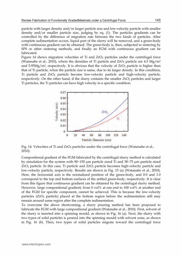
particle with larger density and/or larger particle size and low-velocity particle with smaller density and/or smaller particle size, judging by eq. (1). The particles gradients can be controlled by the difference of migration rate between the two kinds of particles. After complete sedimentation occurs, liquid part of the slurry will be removed, and a green-body with continuous gradient can be obtained. The green-body is, then, subjected to sintering by SPS or other sintering methods, and finally an FGM with continuous gradient can be fabricated. Figure 14 shows migration velocities of Ti and ZrO2 particles under the centrifugal force
(Watanabe et al., 2010), where the densities of Ti particle and ZrO2 particle are 4.5 Mg/m3
and 5.95Mg/m3, respectively. It is obvious that the velocity of ZrO2 particle is higher than
that of Ti particle, when the particle size is same, due to its larger density. In this condition,
Ti particle and ZrO2 particle become low-velocity particle and high-velocity particle,
respectively. On the other hand, if the slurry contains the smaller ZrO2 particles and larger
Ti particles, the Ti particles can have high velocity in a specific condition.
Fig. 14. Velocities of Ti and ZrO2 particles under the centrifugal force (Watanabe et al., 2010).
Compositional gradient of the FGM fabricated by the centrifugal slurry method is calculated
by simulation for the system with 90~150 µm particle sized Ti and 38~75 µm particle sized
ZrO2 particle. In this case, Ti particle and ZrO2 particle becomes high-velocity particle and
low-velocity particle, respectively. Results are shown in Fig. 15 (a) (Watanabe et al., 2010).
Here, the horizontal axis is the normalized position of the green-body, and 0.0 and 1.0
correspond to the top and bottom surfaces of the settled green-body, respectively. It is clear
from this figure that continuous gradient can be obtained by the centrifugal slurry method.
However, large compositional gradient, from 0 vol% at one end to 100 vol% at another end
of the FGM for specific component, cannot be achieved. This is because the low-velocity
particles (ZrO2 particle) placed at the bottom region before the sedimentation still may
remain around same region after the complete sedimentation.
To overcome the above shortcoming, a slurry pouring method has been proposed to
fabricate the FGM with large compositional gradient (Watanabe et al., 2010). First, solvent of
the slurry is inserted into a spinning mould, as shown in Fig. 16 (a). Next, the slurry with
two types of solid particles is poured into the spinning mould with solvent zone, as shown
in Fig. 16 (b). Then, two types of solid particles migrate toward the centrifugal force
www.intechopen.com

Nanocomposites with Unique Properties and Applications in Medicine and Industry 144
direction, as shown in Fig. 16 (c). The existence of solvent zone increases the sedimentation
period. As a result, large compositional gradient, for example from 0vol% at one end to
100vol% at another end, can be fabricated.
Fig. 15. Volume fraction distributions of Ti and ZrO2 particles within the FGMs by the centrifugal slurry method (a) and by the centrifugal slurry-pouring method (b) obtained by the computer simulation (Watanabe et al., 2010). Width of solvent zone is 100mm.
Fig. 16. Schematic illustrations of the centrifugal slurry-pouring method.
The computer simulation is conducted for the centrifugal slurry-pouring method, and
results are shown in Fig. 15 (b), here the width of solvent zone is 100mm (Watanabe et al.,
2010). It is clear from this figure that the FGM has a continuous gradient. It should be
pointed out that the volume fraction of Ti at the normalized position of 0.0 is 0%, while
100% at 1.0 position. Thus, a large compositional gradient can be achieved by the centrifugal
slurry-pouring method.
In order to verify and confirm the above simulation results, experiments were also
conducted without and with the solvent zone. For simplicity, centrifugal force is not applied
and particles were allowed to settle by gravity. After complete settlement of the particles,
liquid is removed and the green-body is dried. The green-body was sintered by SPS method
www.intechopen.com

Review Fabrication of Functionally GradedMaterials under a Centrifugal Force 145
at 1300 oC for 5 minutes under applied stress of 30 MPa. FGMs obtained by SPS method
have cylindrical shape with 20 mm in diameter.
Figures 17 (a) and (b) show experimental results of volume fractional gradients within the FGMs fabricated by the centrifugal slurry method (width of solvent zone is 0mm) and centrifugal slurry-pouring method (width of solvent zone: 100mm), respectively (Watanabe et al., 2010). Without the solvent zone, compositional gradient is limited as shown in Fig. 17 (a), whereas large compositional gradient, the range is between 0vol% and 100vol%, is achieved by the centrifugal slurry method with the solvent zone (the centrifugal slurry-pouring method). Good agreement is found between the experimental and calculated profile.
Fig. 17. Experimental results of volume fractional gradients within the FGMs fabricated by (a) the centrifugal slurry method (Width of solvent zone: 0mm) and (b) centrifugal slurry-pouring method (Width of solvent zone: 100mm), (Watanabe et al., 2010).
4. Centrifugal pressurization method
4.1 Centrifugal mixed-powder method
As a more developed fabrication method of FGMs under the centrifugal force, the
centrifugal mixed-powder method was recently proposed by Watanabe et al. (Watanabe et
al., 2009). As a first step of the process, a powder mixture of matrix metal particles, A, and
dispersion-particles, B, is inserted into a spinning mould, as shown in Fig. 18 (a). Then,
matrix metal ingot, A, is melted and poured into the spinning mould with powder mixture
A + B, as shown in Fig. 18 (b). As a result, the molten matrix metal, A, penetrates into the
space between the particles by the centrifugal force pressure, as shown in Fig. 18 (c). At the
same time, powder of matrix metal, A, is melted by the heat from the molten matrix poured
from a crucible, as shown in Fig. 18 (d). Finally, an FGM ring with dispersion-particles, B,
distributed on its surface, can be obtained, as shown in Fig. 18 (e).
www.intechopen.com

Nanocomposites with Unique Properties and Applications in Medicine and Industry 146
Fig. 18. The schematic description of the centrifugal mixed-powder method (Watanabe et al., 2010).
Cu-30vol%SiC mixed-powder was fabricated using pure Cu particles (99.9%, 1 mm and < 45m in diameter) and SiC particles (150 m). Using this mixed-powder, Cu/SiC FGM was fabricated by the centrifugal mixed-powder method using vertical-type centrifugal casting machine. The applied centrifugal force was G = 100, and the spinning mould containing the powder mixture was heated up to 800 oC. Then, molten Cu with purity of 99.9% was poured into the spinning mould (Watanabe et al., 2009).
Fig. 19. Microstructures of a Cu/SiC FGM fabricated by the centrifugal mixed-powder method (Watanabe et al., 2009).
When the Cu/SiC FGM was removed from the mould, no powders dropped out. Therefore, it is considered that all of the SiC particles in the powder mixture remained in the Cu/SiC FGM. SiC particles are observed on the outer surface of the specimen, as shown in Fig. 19 (a) (Watanabe et al., 2009). Moreover, the SiC particles are embedded in Cu matrix, as shown in Figs. 19 (b) and (c). It is found that SiC particles are successfully distributed on the surface of the FGMs by the centrifugal mixed-powder method, and the SiC particles are homogeneously distributed on the surface
www.intechopen.com

Review Fabrication of Functionally GradedMaterials under a Centrifugal Force 147
4.2 Reactive centrifugal casting method Matsuura et al. developed a new technique named reactive casting, which involves an exothermic reaction between elemental liquids, and enables one to produce the liquid of a high melting point intermetallic compound without the need for external heating (Matsuura et al., 2000). A combination of the reactive casting and centrifugal casting can be applied to the fabrication of a Ni-aluminide / steel clad pipe having an excellent resistance to corrosion and oxidation as well as a considerable level of toughness. This novel method is named as a reactive centrifugal casting method (Watanabe et al., 2004a, Watanabe et al., 2011). Ni powder was placed on a spinning steel pipe, as shown in Fig. 19 (a), and molten Al was poured into the steel pipe, as shown in Fig. 19 (b). The molten Al and Ni powder exothermically reacted and produced a composite layer consisting of Ni-aluminides on the inner surface of the steel pipe, as shown in Fig. 19 (c). The heat generated by the exothermic reaction melted the inner surface of the steel pipe and bonded the composite layer to the steel. Since inexperience Al ingots are used instead of the experienced Al powder, this process will reduce the production cost.
Fig. 20. Schematic illustrations of the reactive centrifugal casting method.
Figure 20 shows the SEM photograph of specimen fabricated under G = 80. The pouring
temperature of the Al liquid and the preheating temperature of nickel powder were 1200 oC
and 700 oC, respectively. A wide region having homogeneous microstructures can be
observed in the composite layer of the sample. In a region away from the joint interface,
however, the graded microstructure was formed. It was shown that the reaction is
remarkably promoted by increasing the pouring temperature of Al, the preheating
temperature of the nickel and the centrifugal force. It is also found that the amounts of
initial Al and Ni play an important role in the control of the microstructure.
Fig. 21. Typical SEM photograph of the Ni-aluminide/steel clad pipe fabricated by the reactive centrifugal casting method (Watanabe et al., 2004a).
www.intechopen.com

Nanocomposites with Unique Properties and Applications in Medicine and Industry 148
5. Conclusion
Functionally graded materials (FGMs) can be fabricated under a centrifugal force, by which it is possible to produce the FGMs with continuous gradients. Fabrication methods of FGMs under the centrifugal force are classified into three categories, namely centrifugal method, centrifugal slurry method and centrifugal pressurization method. We have emphasized the use of the FGM fabrication methods under the centrifugal force as ones of the practical methods, since it has the feasibility of scaling up to mass production at a low cost. Although this chapter is mainly based on the studies by the authors, some other investigators have also fabricated FGMs using a similar method. The research activity in this field is continually increasing.
6. Acknowledgments
This work is supported by “Tokai Region Nanotechnology Manufacturing Cluster in KNOWLEDGE CLUSTER INITIATIVE” by the Ministry of Education, Culture, Sports, Science and Technology of Japan. One of the authors (YW) gratefully acknowledges the financial support from “The Light Metal Educational Foundation Inc. of Japan”.
7. References
Fukui, Y. (1991). Fundamental Investigation of Functionally Gradient Material Manufacturing System using Centrifugal Force. JSME Int. J. Series III, Vol.34, No. 1, (March, 1991), pp. 144-148, ISSN 0914-8825.
Fukui, Y. & Watanabe, Y. (1996). Analysis of Thermal Residual Stress in a Thick-Walled Ring of Duralcan Base Al-SiC Functionally Graded Material, Metal. Mater. Trans. A, Vol. 27A, No. 12, (December, 1996), pp. 4145-4151, ISSN 1073-5623 (Print), 1543-1940 (Online).
Hattori, Y.; Sato, H.; Miura-Fujiwara, E. & Watanabe, Y. (2010). Estimation of the Cooling Rate Distribution by means of Lamellar Spacing of Al-Al2Cu Eutectic Structure during Fabrication of FGM under Centrifugal Force, Functionally Graded Materials, Vol. 24, (2010), pp. 17-22, ISBN 978-4-9901902-6-2.
Kang, C. G. & Rohatgi, P. K. (1996). Transient Thermal Analysis of Solidification in a Centrifugal Casting for Composite Materials Containing Particle Segregation. Metall Mater Trans B, Vol. 27B, No. 2 (April, 1996), pp. 277-285, ISSN 1073-5615 (Print) 1543-1916 (Online).
Matsuura, K.; Jinmon H.; Hirashima, Y.; Khan, T. I. & Kudoh, M. (2000). Reactive Casting of Ni-Al-Fe Ternary Intermetallic Alloys. ISIJ Int., Vol. 40, No. 2 (February, 2000), pp. 161-166, ISSN 0915-1559
Miyamoto, Y.; Kaysser, W. A.; Rabin, B. H.; Kawasaki, A. & Ford, R. G. (Edts.), (1999). Functionally Graded Materials: Design, Processing and Applications, Kluwer Academic Publishers, ISBN 0-412-60760-3, Boston, USA.
Ogawa, T.; Watanabe, Y.; Sato, H., Kim, I-S & Fukui, Y. (2006). Theoretical Study on Fabrication of Functionally Graded Material with Density Gradient by a Centrifugal Solid-Particle Method, Composites Part A, Vol. 37, No. 12, (December, 2006), pp. 2194-2200, ISSN 1359-835X.
www.intechopen.com

Review Fabrication of Functionally GradedMaterials under a Centrifugal Force 149
Sequeira, P. D.; Watanabe, Y.; Eryu, H.; Yamamoto, T. & Matsuura, K. (2007). Effects of Platelet Size and Mean Volume Fraction on Platelet Orientation and Volume Fraction Distributions in Functionally Graded Material Fabricated by a Centrifugal Solid-Particle Method. Trans. ASME, Journal of Engineering Materials and Technology, Vol. 129, No. 2, (April, 2007), pp. 304-312, ISSN 0094-4289.
Suresh, S. & Mortensen, A. (1998). Fundamentals of Functionally Graded Materials, Processing and Thermomechanical Behaviour of Graded Metals and Metal-Ceramic Composites, Communications Ltd., ISBN 1-86125-063-0, London, UK.
Uemura, S.; Noda, Y.; Shinohara, Y. & Watanabe, Y. (ed.) (2010). Development and Technology of Functionally Graded Materials (in Japanese), CMC Publishing Co.,Ltd., ISBN 978-4-7813-0123-5, Tokyo, Japan.
Watanabe, Y.; Yamanaka, N. & Fukui, Y. (1998). Control of Composition Gradient in a Metal-Ceramic Functionally Graded Material Manufactured by the Centrifugal Method. Composites Part A, Vol. 29A, No. 5-6, (1998), pp. 595-601, ISSN 1359-835X.
Watanabe, Y.; Yamanaka, N. & Fukui, Y. (1999). Wear Behavior of Al-Al3Ti Composite Manufactured by Centrifugal Method. Metall. Mater. Trans. A, Vol. 30A, No. 12, (December, 1999), pp. 3253-3261, ISSN 1073-5623.
Watanabe, Y.; Eryu, H. & Matsuura, K. (2001). Evaluation of Three-Dimensional Orientation of Al3Ti Platelet in Al based FGMs Fabricated by a Centrifugal Casting Technique. Acta Mater., Vol. 49, No. 5, (March, 2001), pp. 775-783, ISSN 1359-6454.
Watanabe, Y.; Kawamoto, A. & Matsuda, K. (2002). Particle Size Distributions of Functionally Graded Materials Fabricated by Centrifugal Solid-Particle Method. Comp. Sci. Tech., Vol. 62, No. 6, (May, 2002), pp. 881-888, ISSN 0266-3538.
Watanabe, Y.; Watanabe, S. & Matsuura, K. (2004a). Nickel-Aluminides/Steel Clad Pipe Fabricated by Reactive Centrifugal Casting Method from Liquid Aluminum and Solid Nickel. Metall. Mater. Trans. A, Vol. 35A, No. 5, (May, 2004), pp. 1517-1524, ISSN 1073-5623.
Watanabe, Y.; Sato, R.; Matsuda, K. & Fukui, Y. (2004b). Evaluation of Particle Size and Particle Shape Distributions in Al-Al3Ni FGMs Fabricated by a Centrifugal in-situ Method. Science and Engineering of Composite Materials, Vol. 11, No. 2-3, (2004), pp. 185-199, ISSN 0334-181X.
Watanabe, Y.; Kim, I-S. & Fukui, Y. (2005). Microstructures of Functionally Graded Materials Fabricated by Centrifugal Solid-Particle and in-situ Methods. Metals and Materials International, Vol. 11, No. 5, (October, 2005), pp. 391-399, ISSN 1598-9623.
Watanabe, Y. & Oike, S. (2005). Formation Mechanism of Graded Composition in Al-Al2Cu Functionally Graded Materials Fabricated by a Centrifugal in situ Method. Acta Mater., Vol. 53, No. 6, (April, 2005), pp. 1631-1641, ISSN 1359-6454.
Watanabe, Y.; Sato, H. & Fukui, Y. (2008). Wear Properties of Intermetallic Compound Reinforced Functionally Graded Materials Fabricated by Centrifugal Solid-particle and In-Situ Methods. Journal of Solid Mechanics and Materials Engineering, Vol. 2, No. 7, (July, 2008), pp. 842-853, EISSN 1880-9871.
Watanabe, Y.; Inaguma, Y.; Sato, H. & Miura-Fujiwara, E. (2009). A Novel Fabrication Method for Functionally Graded Materials under Centrifugal Force: The Centrifugal Mixed-Powder Method. Materials, Vol. 2, No. 4, (December, 2009), pp. 2510-2525, EISSN 1996-1944.
www.intechopen.com

Nanocomposites with Unique Properties and Applications in Medicine and Industry 150
Watanabe, Y.; Miura-Fujiwara, E. & Sato, H. (2010). Fabrication of Functionally Graded Materials by Centrifugal Slurry-Pouring Method and Centrifugal Mixed-Powder Method. J. Jpn. Soc. Powder Powder Metallurgy, Vol. 57, No. 5, (May, 2010), pp. 321-326, ISSN 0532-8799.
Watanabe, Y.; Inaguma, Y. & Sato, H. (2011). Cold Model for Process of a Ni-aluminide/Steel Clad Pipe by a Reactive Centrifugal Casting Method. Mater. Lett., Vol. 65, No. 3, (February 2011), pp. 467–470, ISSN 0167-577X.
www.intechopen.com

Nanocomposites with Unique Properties and Applications inMedicine and IndustryEdited by Dr. John Cuppoletti
ISBN 978-953-307-351-4Hard cover, 360 pagesPublisher InTechPublished online 23, August, 2011Published in print edition August, 2011
InTech EuropeUniversity Campus STeP Ri Slavka Krautzeka 83/A 51000 Rijeka, Croatia Phone: +385 (51) 770 447 Fax: +385 (51) 686 166www.intechopen.com
InTech ChinaUnit 405, Office Block, Hotel Equatorial Shanghai No.65, Yan An Road (West), Shanghai, 200040, China
Phone: +86-21-62489820 Fax: +86-21-62489821
This book contains chapters on nanocomposites for engineering hard materials for high performance aircraft,rocket and automobile use, using laser pulses to form metal coatings on glass and quartz, and also tungstencarbide-cobalt nanoparticles using high voltage discharges. A major section of this book is largely devoted tochapters outlining and applying analytic methods needed for studies of nanocomposites. As such, this book willserve as good resource for such analytic methods.
How to referenceIn order to correctly reference this scholarly work, feel free to copy and paste the following:
Yoshimi Watanabe and Hisashi Sato (2011). Review Fabrication of Functionally Graded Materials under aCentrifugal Force, Nanocomposites with Unique Properties and Applications in Medicine and Industry, Dr. JohnCuppoletti (Ed.), ISBN: 978-953-307-351-4, InTech, Available from:http://www.intechopen.com/books/nanocomposites-with-unique-properties-and-applications-in-medicine-and-industry/review-fabrication-of-functionally-graded-materials-under-a-centrifugal-force

© 2011 The Author(s). Licensee IntechOpen. This chapter is distributedunder the terms of the Creative Commons Attribution-NonCommercial-ShareAlike-3.0 License, which permits use, distribution and reproduction fornon-commercial purposes, provided the original is properly cited andderivative works building on this content are distributed under the samelicense.