Review Exam III. Chapter 10 Sinusoidally Driven Oscillations.
37
Review Exam III
-
Upload
anthony-franklin -
Category
Documents
-
view
221 -
download
1
Transcript of Review Exam III. Chapter 10 Sinusoidally Driven Oscillations.

Review
Exam III

Chapter 10
Sinusoidally Driven Oscillations

A Simple Driving System• The door starts with
complex motions (transient) that settle down to sinusoidal, no matter the motor rate.
• The final frequency is always the driving frequency of the motor ().
• The amplitude of the oscillations depends on how far from the natural frequency the motor is.

Amplitude vs. Frequency
Observed Motions
/o Door Lags
<< 1 0
< 1 Small
= 1 ¼-cycle
>> 1 ½-cycle

Nature of the Transient
• Damped Harmonic Oscillator
– Small Damping
Driven Oscillator - Lightly Damped
-0.3
-0.2
-0.1
0
0.1
0.2
0.3
0.4
0 1 2 3 4 5
Time
Am
plit
ud
e
Driven Oscillator - Heavier Damping
-0.2
-0.1
0
0.1
0.2
0.3
0 1 2 3 4 5
Time
Am
plit
ud
e– Heavier Damping

Properties of a Sinusoidally Driven System
• At startup there is a transient that is made up of the damped sinusoids of all of the natural frequencies.
• Once the transient is gone the steady state is at the driving frequency. When the driving frequency is close to one of the natural frequencies, the amplitude is a maximum and resembles that natural mode.

Damping and the Steady State
• As long as we are far from natural frequency, damping doesn’t affect the steady state.
• Near the natural frequency, damping does have an effect.

Damping and the Steady State
Small damping
Large damping
Am
plit
ude
Frequency
W½

Trends with Damping
• Oscillations die out quicker for larger damping.
• As damping increases the maximum amplitude decreases
• Larger damping means a broader curve.

Simple Two Mass Model

Driving Point Response Function or Resonance Curve
Am
plit
ude
Frequency

A Two-Dimensional Oscillator
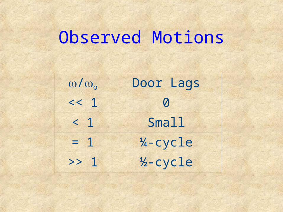
The tray is clamped at three places. Sensors ( )and drivers ( )are used as pairs in the locations indicated.
Drivers Ability to Excite ModesSensors Ability to Detect Modes
• If a driver/sensor falls on the nodal line of a mode, that mode will not be excited
• If a driver/sensor falls between nodal lines of a mode, that mode will be excited

Superposing Two Modes

Summary
• Altering the location of either the driver or the detector will greatly alter what the transfer response curve will be.
• Altering the driver frequency will also change the response.

Chapter 11
Room Acoustics I:
Excitation of the Modes
and the Transmission of Impulses
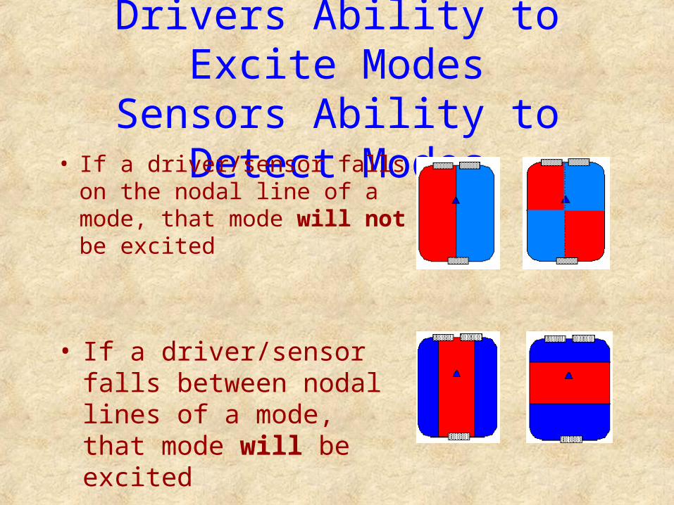
Observations
• Air has elasticity ("stiffness")
• Air has mass
• Air must support modes of vibration
stiffness coefficientfrequency =
moving mass

Simple Source
• Aperture for the source (size of the speaker) is small compared to the wavelength.– Loudspeakers are wide enough to not qualify as simple
sources at high frequency, when the wavelength is short.
• Locate at antinode to stimulate a room mode• Locate at node to suppress room mode
– Large numbers of modes stimulated together
– Hard to isolate one mode

Room Modes
• Room modes are approximately sinusoidal regardless of the driving frequency.
• There is a transient at the natural frequency and a steady state frequency at the driving frequency.
• Number of modes Room Volume
• Number of modes Frequency2

Observations
• Simple decay behavior is observed when the modes are strongly excited
• When modes are weakly excited transients come in irregular bursts

Impulsive Excitation - Changes in Response with Distance
Source Impulse
Nearby Response
Farther Away
And Farther Still

Room Response to Impulse
• Speed of Sound Delay
• Damped Harmonic Oscillator

Reverberation
• Trev is defined to be the time for the sound to decay to 0.001 its initial amplitude.– Trev = 9.97 T½

Room Reflections• Wave shape is preserved in reflections
• Superposition of all these gives the background, irregular signal.
• There is a time delay for the reflected wave as well as a smaller amplitude
a 1/d Absorption by wall

Flat Wall Reflections

Reflections and Scattering
• Reflection off of large, flat objects (walls) does not distort the signal. Follows the same Law of Reflection as light.
• Small, compact objects act as new sources of sound, emanating a modified signal uniformly in all directions.
• Large Objects (furniture) act intermediate between the walls and the small objects.

Chapter 12
Room Acoustics II:
The Listener and the Room

Acoustical Extremes
• Anechoic Chamber– Suppress all room reflections and scattering
• Real Room– Human ears are much better in discriminating
small changes in pitch, loudness, and tone color in a real room.

Human Hearing Response
• The human nervous system makes a running average amplitude (loudness) of the partials based on information received from the two ears.
• Waveforms will be correlated if the separation of ears is less than one-half wavelength– If your ears have waveform that are too similar,
less information is available

Gathering More Information
• Move your head
• Walk around

Precedence Effect
• The ear will combine a set of reduplicated sounds (echoes) and hear them as one provided…– that they arrive within about 35 ms of each
other, and– that the waveforms are sufficiently similar.
• The one tone is heard without any delay.

More Precedence Effect
• The perceived time of arrival is that of the first sound.
• The apparent position of the sound is the position of the first sound.
• The effect is present even when the later arrivals have more amplitude.– but less than about three times the amplitude of
the first

Loudspeaker Response Regions
• Below speaker resonance response falls rapidly– This is the frequency that the cone oscillates at
if displaced from rest
• Mid-range is approximately constant
• High frequency cut-off– Cone is larger than a few wavelengths of the
sound
High Frequency Cutoff
• If wavelength of sound is shorter than half the circumference of the speaker cone, then the response is poor ( < ½C = ½D, D = diamter of cone)
• The beam pattern is less homogeneous above the high frequency cut off

Typical Speaker Arrangement
Woofer
Tweeter
Mid-range
Lows
Middles
Highs
From Amplifier
D

Crossover
• Consider frequencies near where one speaker hands off to another– We can have a situation of two sources of
almost equal strength– Speaker separations by D = ½ , 3/2 , 5/2 ,
etc. will lead to total destructive interference for most room modes