Review Exam 1 - Electrical Engineering at New Mexico Techerives/308_11/Review1.pdf ·...
21
EE 308 Spring 2011 Review Exam 1 • Numbers – Decimal to Hex (signed and unsigned) – Hex to Decimal (signed and unsigned) – Binary to Hex – Hex to Binary – Addition and subtraction of fixed-length hex numbers – Overflow, Carry, Zero, Negative bits of CCR • Programming Model – Internal registers – A, B, (D = AB), X, Y, SP, PC, CCR • Addressing Modes and Effective Addresses – INH, IMM, DIR, EXT, REL, IDX (Not Indexed Indirect) – How to determine effective address • Instructions – What they do - Core Users Guide – What machine code is generated – How many cycles to execute – Effect on CCR – Branch instructions – which to use with signed and which with unsigned • Machine Code – Reverse Assembly • Stack and Stack Pointer – What happens to stack and SP for instructions (e.g., PSHX, JSR) – How the SP is used in getting to and leaving subroutines • Assembly Language – Be able to read and write simple assembly language program – Know basic assembler directives – e.g., equ, dc.b, ds.w Flow charts
Transcript of Review Exam 1 - Electrical Engineering at New Mexico Techerives/308_11/Review1.pdf ·...

EE 308 Spring 2011
Review Exam 1
• Numbers
– Decimal to Hex (signed and unsigned) – Hex to Decimal (signed and unsigned) – Binary to Hex – Hex to Binary – Addition and subtraction of fixed-length hex numbers – Overflow, Carry, Zero, Negative bits of CCR
• Programming Model
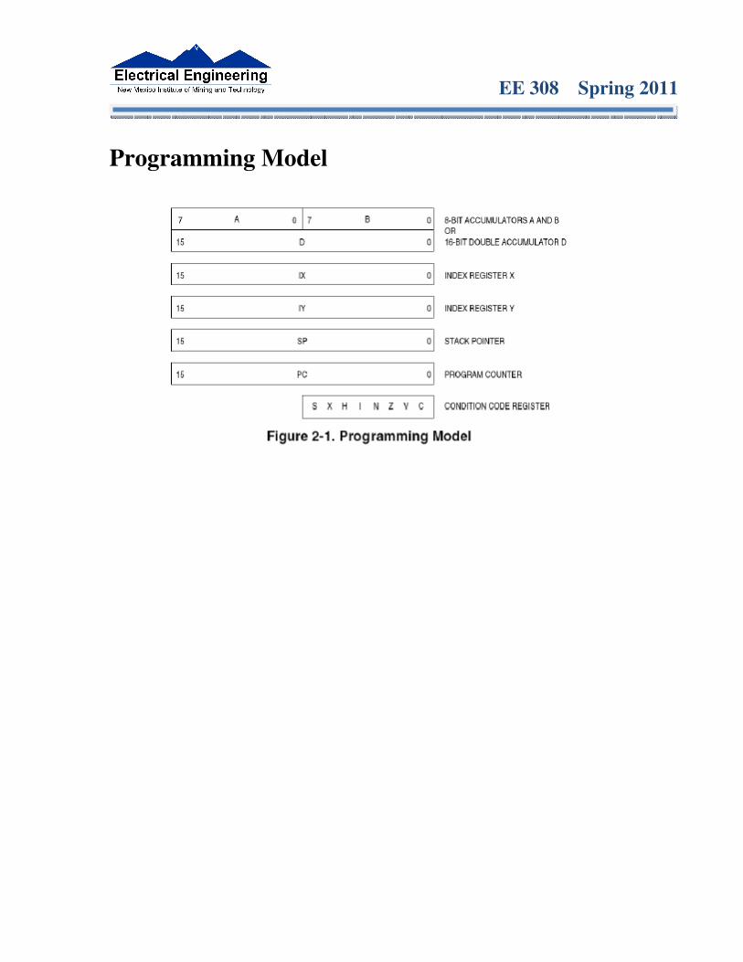
– Internal registers – A, B, (D = AB), X, Y, SP, PC, CCR • Addressing Modes and Effective Addresses
– INH, IMM, DIR, EXT, REL, IDX (Not Indexed Indirect) – How to determine effective address
• Instructions
– What they do - Core Users Guide – What machine code is generated – How many cycles to execute – Effect on CCR – Branch instructions – which to use with signed and which with unsigned
• Machine Code
– Reverse Assembly • Stack and Stack Pointer
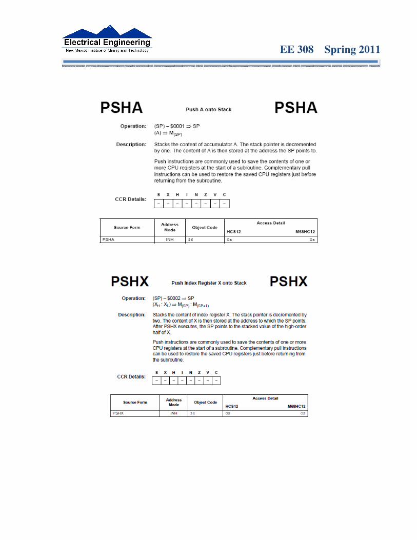
– What happens to stack and SP for instructions (e.g., PSHX, JSR) – How the SP is used in getting to and leaving subroutines
• Assembly Language
– Be able to read and write simple assembly language program – Know basic assembler directives – e.g., equ, dc.b, ds.w Flow charts

EE 308 Spring 2011
Binary, Hex and Decimal Numbers (4-bit representation)
Binary
Hex
Decimal
0000 0001 0010 0011 0100 0101 0110 0111 1000 1001 1010 1011 1100 1101 1110 1111
0 1 2 3 4 5 6 7 8 9 A B C D E F
0 1 2 3 4 5 6 7 8 9
10 11 12 13 14 15
Binary to Unsigned Decimal: Convert Binary to Unsigned Decimal 1111011 2
1 x 26 + 1 x 2 5 + 1 x 2 4 + 1 x 2 3 + 0 x 2 2 + 1 x 2 1 + 1 x 2 0
1 x 64 + 1 x 32 + 1 x 16 + 1 x 8 + 0 x 4 + 1 x 2 + 1 x 1 123 10
Hex to Unsigned Decimal Convert Hex to Unsigned Decimal 82D6 16 8 x 163 + 2 x 162 + 13 x 161 + 6 x 160
8 x 4096 + 2 x 256 + 13 x 16 + 6 x 1 33494 10
EE 308 Spring 2011
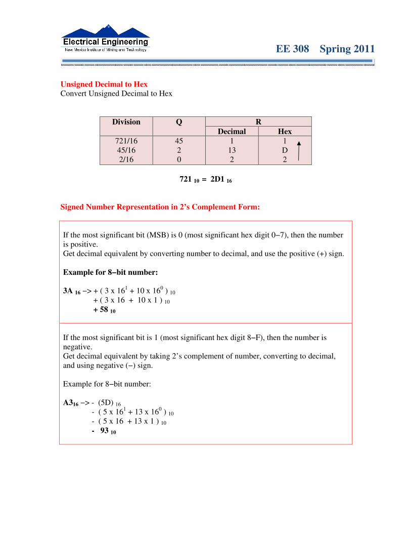
Unsigned Decimal to Hex Convert Unsigned Decimal to Hex
Division Q R Decimal Hex
721/16 45/16 2/16
45 2 0
1 13 2
1 D 2
721 10 = 2D1 16
Signed Number Representation in 2’s Complement Form:
If the most significant bit (MSB) is 0 (most significant hex digit 0−7), then the number is positive. Get decimal equivalent by converting number to decimal, and use the positive (+) sign. Example for 8−bit number: 3A 16 −> + ( 3 x 161 + 10 x 160 ) 10 + ( 3 x 16 + 10 x 1 ) 10 + 58 10
If the most significant bit is 1 (most significant hex digit 8−F), then the number is negative. Get decimal equivalent by taking 2’s complement of number, converting to decimal, and using negative (−) sign. Example for 8−bit number: A316 −> - (5D) 16
- ( 5 x 161 + 13 x 160 ) 10 - ( 5 x 16 + 13 x 1 ) 10 - 93 10

EE 308 Spring 2011
One’s complement table makes it simple to finding 2’s complements
To take two’s complement, add one to one’s complement. Take two’s complement of D0C3:
2F3C + 1 = 2F3D
One’s complement
One’s complement

EE 308 Spring 2011
Addition and Subtraction of Binary and Hexadecimal Numbers Setting the C (Carry), V (Overflow), N (Negative) and Z (Zero) bits How the C, V, N and Z bits of the CCR are changed N bit is set if result of operation is negative (MSB = 1) Z bit is set if result of operation is zero (All bits = 0) V bit is set if operation produced an overflow C bit is set if operation produced a carry (borrow on subtraction) Note: Not all instructions change these bits of the CCR Addition of Hexadecimal Numbers ADDITION: C bit set when result does not fit in word V bit set when P + P = N or N + N = P N bit set when MSB of result is 1 Z bit set when result is 0 7A AC +52 +72 ----- ------ CC 1E C: 0 C: 1 V: 1 V: 0 N: 1 N: 0 Z: 0 Z: 0

EE 308 Spring 2011
Subtraction of Hexadecimal Numbers SUBTRACTION: C bit set on borrow (when the magnitude of the subtrahend is greater than the minuend V bit set when N - P = P or P - N = N N bit set when MSB is 1
Z bit set when result is 0 7A 2C -5C -72 ----- ------ 1E BA C: 0 C: 1 V: 0 V: 0 N: 0 N: 1 Z: 0 Z: 0
EE 308 Spring 2011
Programming Model

EE 308 Spring 2011
Addressing Modes and Effective Addresses The Inherent (INH) addressing mode Instructions which work only with registers inside ALU
ABA ; Add B to A (A) + (B) → A 18 06
CLRA ; Clear A 0 → A 87 The HC12 does not access memory - There is no effective address
The Extended (EXT) addressing mode Instructions which give the 16−bit address to be accessed
LDAA $1000 ; ($1000) → A B6 10 00 Effective Address: $1000
STAB $1003 ; (B) → $1003 7B 10 03 Effective Address: $1003 Effective address is specified by the two bytes following op code
EE 308 Spring 2011
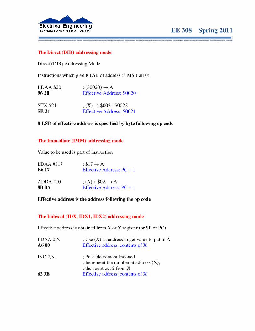
The Direct (DIR) addressing mode Direct (DIR) Addressing Mode Instructions which give 8 LSB of address (8 MSB all 0)
LDAA $20 ; ($0020) → A 96 20 Effective Address: $0020
STX $21 ; (X) → $0021:$0022 5E 21 Effective Address: $0021 8-LSB of effective address is specified by byte following op code
The Immediate (IMM) addressing mode Value to be used is part of instruction
LDAA #$17 ; $17 → A B6 17 Effective Address: PC + 1
ADDA #10 ; (A) + $0A → A 8B 0A Effective Address: PC + 1 Effective address is the address following the op code The Indexed (IDX, IDX1, IDX2) addressing mode Effective address is obtained from X or Y register (or SP or PC) LDAA 0,X ; Use (X) as address to get value to put in A A6 00 Effective address: contents of X INC 2,X− ; Post−decrement Indexed
; Increment the number at address (X), ; then subtract 2 from X
62 3E Effective address: contents of X

EE 308 Spring 2011
INDEXED ADDRESSING MODES
EE 308 Spring 2011
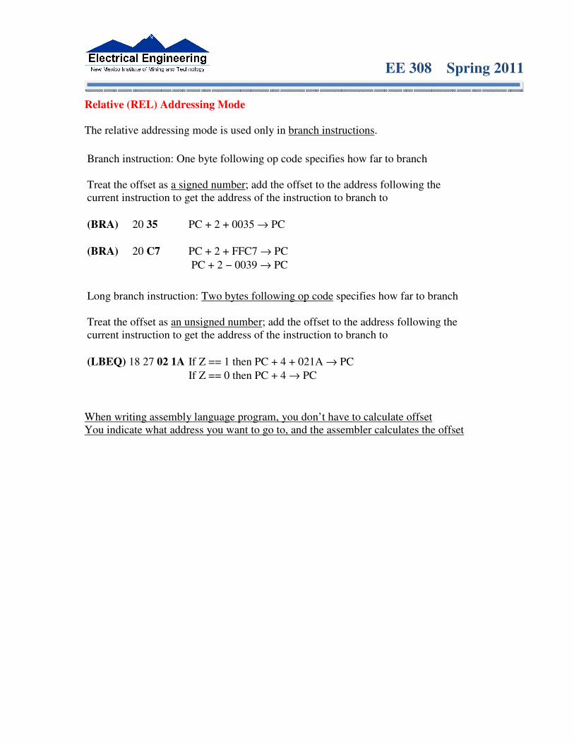
Relative (REL) Addressing Mode
The relative addressing mode is used only in branch instructions.
Branch instruction: One byte following op code specifies how far to branch Treat the offset as a signed number; add the offset to the address following the current instruction to get the address of the instruction to branch to
(BRA) 20 35 PC + 2 + 0035 → PC
(BRA) 20 C7 PC + 2 + FFC7 → PC
PC + 2 − 0039 → PC
Long branch instruction: Two bytes following op code specifies how far to branch Treat the offset as an unsigned number; add the offset to the address following the current instruction to get the address of the instruction to branch to
(LBEQ) 18 27 02 1A If Z == 1 then PC + 4 + 021A → PC
If Z == 0 then PC + 4 → PC
When writing assembly language program, you don’t have to calculate offset You indicate what address you want to go to, and the assembler calculates the offset

EE 308 Spring 2011
Instructions: Machine code, how many cycles to execute, effect on CCR, and branch instructions CPU cycles of the 68HC12 • 68HC12 works on 48 MHz clock • Each processor cycle takes 41.7 ns (1/24 MHz) to execute • You can determine how many cycles an instruction takes by looking up the CPU cycles for that instruction in the Core Users Guide.
2000 org $2000 ; Inst Mode Cycles 2000 C6 0A ldab #10 ; LDAB (IMM) 1 2002 87 loop: clra ; CLRA (INH) 1 2003 04 31 FC dbne b,loop ; DBNE (REL) 3 2006 3F swi ; SWI 9
The program executes the ldab #10 instruction once (which takes one cycle). It then goes through loop 10 times (which has two instructions, on with one cycle and one with three cycles), and finishes with the swi instruction (which takes 9 cycles). Total number of cycles: 1 + 10 × (1 + 3) + 9 = 50 50 cycles = 50 × 41.7 ns/cycle = 2.08 µs

EE 308 Spring 2011
Effects of instructions on CCR during execution of program.
EE 308 Spring 2011
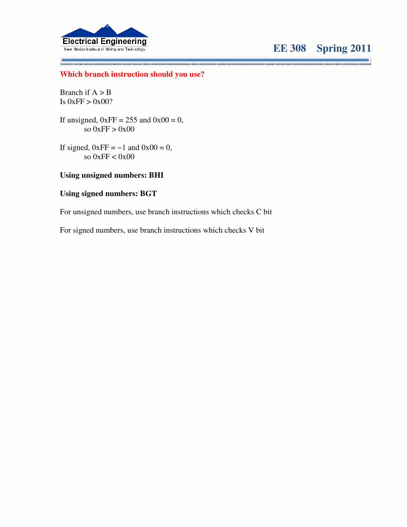
Which branch instruction should you use? Branch if A > B Is 0xFF > 0x00? If unsigned, 0xFF = 255 and 0x00 = 0,
so 0xFF > 0x00 If signed, 0xFF = −1 and 0x00 = 0,
so 0xFF < 0x00 Using unsigned numbers: BHI Using signed numbers: BGT For unsigned numbers, use branch instructions which checks C bit For signed numbers, use branch instructions which checks V bit

EE 308 Spring 2011
Reverse Assembly
Disassembly of an HC12 Program • It is sometimes useful to be able to convert HC12 op codes into mnemonics. For example, consider the hex code:
ADDR DATA --------------------------------------------------------- 2000 C6 05 CE 20 00 E6 01 18 06 04 35 EE 3F
• To determine the instructions, use: Table A-2 of the HCS12 Core Users Guide to start with. Table A-3 for indexed addressing mode Table A-5 for transfer and exchange instructions Table A-6 for postbyte encoding.
• Use up all the bytes for one instruction, then go on to the next instruction.
C6 05 ⇒⇒⇒⇒ LDAA #$05 two-byte LDAA, IMM addressing mode
CE 20 00 ⇒⇒⇒⇒ LDX #$2000 three-byte LDX, IMM addressing mode
E6 01 ⇒⇒⇒⇒ LDAB 1,X two to four-byte LDAB, IDX addressing mode. Operand 01 => 1,X, a 5b constant offset which uses only one postbyte
18 06 ⇒⇒⇒⇒ ABA two-byte ABA, INH addressing mode
04 35 EE ⇒⇒⇒⇒ DBNE X,(-18) three-byte loop instruction Postbyte 35 indicates DBNE X, negative
3F ⇒⇒⇒⇒ SWI one-byte SWI, INH addressing mode

EE 308 Spring 2011
Stack and Stack Pointer THE STACK AND THE STACK POINTER • When we use subroutines and interrupts it is essential to have such a storage region. • Such a region is called a Stack. • The Stack Pointer (SP) register is used to indicate the location of the last item put onto the stack. • When you put something onto the stack (push onto the stack), the SP is decremented before the item is placed on the stack. • When you take something off of the stack (pull from the stack), the SP is incremented after the item is pulled from the stack. • Before you can use a stack you have to initialize the Stack Pointer to point to one value higher than the highest memory location in the stack. • Use the LDS (Load Stack Pointer) instruction to initialize the stack point. • The LDS instruction is usually the first instruction of a program which uses the stack. • The stack pointer is initialized only one time in the program.
EE 308 Spring 2011

EE 308 Spring 2011

EE 308 Spring 2011
Subroutines • A subroutine is a section of code which performs a specific task, usually a task which needs to be executed by different parts of a program. • Example:
– Math functions, such as square root • Because a subroutine can be called from different places in a program, you cannot get out of a subroutine with an instruction such as jmp label because you would need to jump to different places depending upon which section of code called the subroutine. • When you want to call the subroutine your code has to save the address where the subroutine should return to. It does this by saving the return address on the stack.
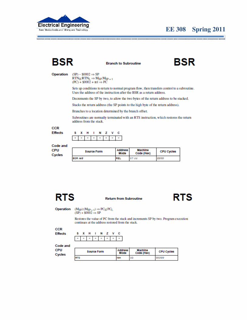
– This is done automatically for you when you get to the subroutine by using the JSR (Jump to Subroutine) or BSR (Branch to Subroutine) instruction. This instruction pushes the address of the instruction following the JSR/BSR instruction on the stack.
• After the subroutine is done executing its code it needs to return to the address saved on the stack.
– This is done automatically for you when you return from the subroutine by using the RTS (Return from Subroutine) instruction. This instruction pulls the return address off of the stack and loads it into the program counter, so the program resumes execution of the program with the instruction following that which called the subroutine.
The subroutine will probably need to use some MC9S12 registers to do its work. However, the calling code may be using its registers for some reason - the calling code may not work correctly if the subroutine changes the values of the HC12 registers.
– To avoid this problem, the subroutine should save the MC9S12 registers before it uses them, and restore the MC9S12 registers after it is done with them.
EE 308 Spring 2011

EE 308 Spring 2011
Example of a subroutine to delay for a certain amount of time ; Subroutine to wait for 100 ms
delay: ldaa #100 ; execute outer loop 100 times loop2: ldx #8000 ; want inner loop to last 1ms
loop1: dbne x,loop1 ; inner loop – 3 cycles x 8000 times
dbne a,loop2 rts
• Want inner loop to last for 1 ms. MC9S12 runs at 24,000,000 cycles/second, so 1 ms is 24,000 cycles. • Inner loop should be 24,000 cycles/ (3 cycles/loop) = 8,000 loops (times)
• Problem: The subroutine changes the values of registers A and X • To solve this problem, save the values of A and X on the stack before using them, and restore them before returning. ; Subroutine to wait for 100 ms
delay: psha ; save registers pshx
ldaa #100 ; execute outer loop 100 times loop2: ldx #8000 ; want inner loop to last 1ms
loop1: dbne x,loop1 ; inner loop – 3 cycles x 8000 times
dbne a,loop2 pulx ; restore registers pula rts