Reverse-Flow Combustor - NASAcauses heat transfer problems to more severe in ... investigated for a...
41
December 1981 Reverse-Flow Combustor I . . . https://ntrs.nasa.gov/search.jsp?R=19820007167 2018-06-08T01:08:10+00:00Z
Transcript of Reverse-Flow Combustor - NASAcauses heat transfer problems to more severe in ... investigated for a...

December 1981
Reverse-Flow Combustor I .
. .
https://ntrs.nasa.gov/search.jsp?R=19820007167 2018-06-08T01:08:10+00:00Z

TECH LIBRARY KAFB, NM
NASA Technical Paper 1945
1981
Natlonal Aeronautlcs and Space Admlnlstratlon
Scientific and Technical Information Branch
0067702
Effect of Fuel Injector Type on Performance and Emissions of Reverse-Flow Combustor
Carl T. Norgren and Stephen M. Riddlebaugh Lewis Research Center Cleueland, Ohio

Summary The combustion process in a reverse-flow
combustor suitable for a small gas turbine engine was investigated to evaluate the effect of fuel injector type on performance and emissions. Fuel injector configurations using pressure-atomizing, spill-flow, air-blast, and air-assist techniques were compared and evaluated on the basis of performance obtained in a full-scale experimental combustor operated at inlet conditions corresponding to takeoff, cruise, low power, and idle and typical of a 16:l-pressure-ratio turbine engine. The combustor was operated over a range of fuel injector spacing. However, fuel injector comparisons are reported primarily for the basic design configuration, which had 18 injectors. A limited comparison at low-power conditions is presented for nine symmetrically spaced injectors.
Major differences in combustor performance and emissions characteristics were experienced with each injector type even though the aerodynamic configuration was common to most combustor models. The fuel injectors evaluated were pressure- atomizing (simplex, duplex, spill-flow return, and fan spray), splash-cone air-blast, multiple-fuel- impingement air-blast, and air-assist injectors. With the basic combustor configuration the spill-flow return injector gave good performance and emission characteristics. Also, if a fuel injector sequencing scheme was incorporated for low-power conditions and idle, high performance and low emissions could be obtained with the splash-cone air-blast injector.
Performance and emissions characteristics obtained with various fuel injector types could not have been predicted from bench-test injector spray characteristics. Reducing the number of fuel injectors generally improved combustion efficiency at low power and idle. Reducing the number of simplex pressure-atomizing fuel injectors from 18 to 6 improved low-power efficiency, but outlet temperature distortions, as indicated by pattern factor, increased.
Introduction Combustor programs are being conducted at the
NASA Lewis Research Center to provide the technology required to improve the reliability and performance of small gas turbine engines. As part of
this effort the effect of various fuel injection techniques on performance has been investigated in a reverse-flow combustor configuration. Performance and emission characteristics are documented for pressure-atomizing, spill-flow, air-blast, and air- assist fuel injectors. The results are compared with those from previous simplex pressure-atomizing fuel injector studies made with the same combustor configuration.
The small gas turbine engine, as designed for general-aviation applications, offers higher power- weight ratios, lower vibrational levels, lower noise and emissions, higher reliability, less maintenance, and easier and more efficient installation than comparable reciprocating engines. Consequently a large potential demand exists in general-aviation applications as well as in the existing and growing market for helicopters. In addition, small gas turbine engines designed for commuter aircraft applications have the potential to conserve fuel and natural resources through optimization of mission, payload, and performance. The predicted economic growth will depend greatly on the ability of small gas turbines to operate efficiently with lower quality fuel over higher cycle efficiencies. Higher cycle efficiency results from increased turbine inlet temperatures and increased operating pressure. Requirements for reliable operation of small combustors under such severe conditions are even more demanding because of size considerations (ref. 1). For example, surface- volume ratio as compared with larger combustors causes heat transfer problems to be more severe in small combustors.
As an approach to investigating the technology involved in small combustor design, a reverse-flow combustor was fabricated by using existing design techniques (ref. 2). The reverse-flow configuration was selected on the basis of an evaluation of performance parameters, manufacturing tolerances, and engine considerations, particularly as applied to rotorcraft.
Fuel dispersion and mixing with the airflow is more critical in the small reverse-flow combustor than in its larger counterpart because a greater number of fuel injectors are required in the small combustor to uniformly disperse the fuel in the primary zone and to provide a satisfactory temperature distribution at the turbine. In addition, the physical passage size of the fuel injector is so small that fouling of the injector due to fuel
I l l111l1l l l - 111ll1ll

t
contamination, gumming, or carbonizing could seriously affect nozzle performance. Consequently the method of fuel injection and the type of fuel distribution selected are major design factors that are more determinative of performance for small combustor configurations than for larger combustors. The reverse-flow combustor system is particularly well adapted to interchanging fuel injectors and evaluating the effect of various fuel injector types since the injector is readily accessible without disturbing the combustor installation.
In this investigation the combustor geometry was fixed and only variations in the fuel injection system were studied. Six fuel injector types encompassing the pressure-atomizing, spill-flow, air-blast, and air- assist techniques were used, and the results are compared with the commercial simplex pressure- atomizing configuration results reported in refer- ence 2. Two additional tests were also conducted with the simplex pressure-atomizing technique to investigate the design problem of fuel injector spacing. Thus the effect of the type of fuel injection system on combustion efficiency, total pressure loss, outlet temperature profile, and pattern factor was investigated for a simulated range of gas turbine
Preheater Exhaust gases from four exhaust J47 combustor cans
1 n r I nd i rec t l y f i r ed
engine conditions for a 16:l compression ratio with Jet A fuel. Performance data for a parametric variation of combustor reference velocity were also obtained as well as data for the emissions of unburned hydrocarbons, carbon monoxide, oxides of nitrogen, and smoke.
Apparatus Test Facility
The test combustor was mounted in the closed- duct facility shown schematically in figure 1. Although the laboratory air supply can maintain airflow rates to 15 kilograms per second (kglsec) at pressure levels to 3000 kilopascals (kPa), tests were conducted to an inlet air pressure of 1600 kPa. Combustion air drawn from the laboratory high- pressure supply was indirectly heated to a temperature of about 720 K in a counterflow-tube heat exchanger. The temperature of the air flowing out of the heat exchanger was automatically controlled by mixing the heated air with varying amounts of cold bypassed air. Airflow through the heat exchanger and bypass flow system and the total
Air f low contro l va lve
r i , i ,- A i r o r i f i c e
/
Laboratory heat exchanger a i r supply
+ I Automat ic a i r temperature control valve
Test i i l L Water sprays J
combustor 1 7.. ̂ I ,’ L TemRerature.
A tmospher ic o r a l t i tude exhaust
rue! I
i n jec to rs J emi;sions. and smoke sample probes
Figure 1. - Schematic of test facil i ty.
2

I
Inst rumentat ion L, station 3 I 0 Liner thermocouple locat ions
b- Ins t rumen ta t i on I stat ion 5
~- - Combustor center l ine
-~
(a) Cross section.
Airflow
(b) Isometric view.
F igure 2 - Reverse-flow combustor. (All d imens ions a re in centimeters. 1
3
I I I1 I I I I lllllll1111llllIIl

pressure of the combustor inlet airflow were regulated by remotely controlled valves, as shown in figure 1.
Combustor
A cross section of the reverse-flow combustor used in this investigation is shown in figure 2(a). An isometric sketch of the reverse-flow combustor is shown in figure 2(b). The combustor is a full-scale, experimental NASA design with a maximum diameter of 38.5 centimeters. The design stresses versatility so that interchanging fuel injectors and modifying or replacing the swirlers, faceplate, liner, and turning sections can be readily accomplished.The design liner isothermal pressure loss is 1.5 percent, and the diffuser dump loss is 0.24 percent. A symmetrical fuel injector spacing in the housing, based on 36 circumferential locations, is used so that 6, 9, 12, or 18 fuel injectors can be flow staged in the combustor by modifying the injector faceplate to maintain symmetry. The airflow distribution and hole sizes in the liner are based on 36 primary and dilution holes. Total mass flows for each air entry location are tabulated in table I. The reverse-flow combustor and housing are shown in figure 3. In figure 3(a) an aft view of the combustor is shown before assembly. In figure 3(b) the combustor is shown partly assembled, and in figure 3(c) it is shown completely assembled in the housing.
Fuel Injectors
The fuel injectors for this program were selected on the basis of a survey of atomization methods. Pressure-atomizing, spill-flow, air-blast, and air- assist methods were considered. A brief review of commercially available injectors indicated that very few injectors would be suitable for small combustor application. A small, commercially available injector was selected for the baseline configuration of this study; two injectors were selected on the basis of availability from outside sources; and four fuel injectors were obtained from an Army-sponsored program to assist in the development of small-scale, high-performance combustors. From this program four different injectors were selected in a multiphase program in which 11 injector configurations were originally considered. A set of fuel injectors was fabricated for each of the four injector types in order to provide 18 injectors in a set. Cross-sectional views of the fuel injectors fabricated especially for this program are shown in figures 4(a) to (d), and the sprays produced by the injectors with liquid MIL- F-7024 used for Jet A simulation are shown in figure 5 . Details of the test procedure are presented in the appendix. In figure 4(e) a cross-sectional view of the air-assist injector is also shown. Fuel injector characteristics are summarized in table 11.
Six of the seven fuel injectors and the mounting struts used in this program are shown in figure 6 . The
TABLE I. - LINER AIRFLOW DISTRIBUTION
A i r entry
Faceplate
P r i m a r y
Dilution
Concentric around fuel injector
Liner cooling
Outer 180'
Inner 180'
Type of entry
Swir ler
Pr imary ho les
Dilution holes
Annulus
Film cooling
Film cooling
Film cooling
~~
Mass f low, percent of total
-
24.8
18 .6
24.1
3.2
13.2
13 .1
3.0
" - .~
Comments
~~ ~ ~~
2.54 cm f rom f i rewal l , 36 holes in outer wall and 36 holes in inner wall
5.72 cm from f i rewal l , 36 holes in outer wall and 36 holes in inner wall
""""""""""""""""""- "
4

la) A f l view of combustor. (b) Combustor l iners.
( c ) Housing.
F igu re 3. - Reverse-f low combustor.
external appearances of the duplex and spill-flow injectors are identical; consequently only one assembly is shown for reference.
Simplex pressure-atomizing injector. -This commercially available injector was selected to establish a reference base as determined by operational limits, performance, and emission levels of the combustor configuration. The injector was 1.1 centimeters (7/16 in.) long with a 0.8centimeter- diameter (5/16 in.) NEF-32-3A thread. All injectors used in this study were sized to provide most of the
fuel flow range required for simulated test conditions and parametric variations as indicated in the section Procedure under Test Conditions. The flow number was 4.8, and the spray angle was 75 O f 5 O . The Sauter mean diameter (SMD) was estimated to be 100 micrometers, as shown in table 11.
Duplex fuel injector. -The duplex injector uses pressure atomization and spin slots to break up the fuel. A variable-area effect is achieved by using two coaxial simplex injectors within the same envelope. The primary flow passage was sized to maintain

Primary __
Return flow -
- Fuel flow -
7 Fuel flow
I I I t " 1 9 m m 7
(b) Spill flow.
a- I diam
(cl Splash cone.
t" .19 mmI
(dl Impingement
Nitrogen iam
(e) Air assist
Figure 4 - Fuel injector schematic.
6

t
(e) Splash cone: supply pressure, 13 kPa differential; (0 Splash cone: supply pressure, 1360 kPa differential; air pressure, 5.5 kPa differential. air pressure, 5.5 kPa differential.
Figure 5. - Spray characteristics of selected fuel injectors.
7

(g) Impingement: supply pressure, 13 k t 3 differentlal; air (h) Impingement: supply pressure, 2040 k b differential; air pressure, 5.5 kPd differential. uressure, 5.5 kPa differential.
Figure 5. - Concluded.
TABLE 11. - FUEL INJECTOR CHARACTERISTICS
Fuel injector
Simplex
Duplex P r i m a r y Secondary
Spill flow
Fan
Splash cone
rmpingement
Air a s s i s t
?low number Wf/.4P1'2
~~
4.8
.67 2.38
3 .1
2.7
6 .4
4.2
2.2
Estimated drop s ize ,
SMD
?loo
130 75
100 - 75
- - - - - - - -
150 - 350
Spray angle
deg
- ~~
75
60 75
90 - 120
50 - 130
200
20 0
- - - - - - - -
.. . ..
""
7 .9 2.7
9 .1
23.6
22.5
""
Patternation, percent
""
1 2 . 6 7 . 3
4 . 4
75.7
16 .1
"" 1
""
1 2 . 3 3.8
7.0
""
54.3
21.4
-
""
1 5 . 6 5 . 3
11 .9
""
19.7
32.8
""
-
aCalculated (ref. 7) . bUniformity of the injector spray pattern measured by use of a six-segment patternator. The
flow into each 60' segment is collected in a glass tube until one is filled. The reading is obtained by measuring the percentage difference of each tube from the filled tube. (An empty tube is indicated by a high percentage reading.) The l isted results were obtained from the average of the 18 injectors. The duplex and spill-flow values were obtained at a fue l p ressure of 300 psia and the splash and impingement values of 50 psia.
8

Impingement \ \ \ \ \
Splash cone ,- Simplex r Fan I- Sprll flow or A i r assist
\ I I \ duplex (identical
I I I
C-79-3152
Figure 6. - Assembled fuel in~ectors.
pressure in order to ensure atomization at the minimum flow rate; the secondary passage was large enough to limit the maximum pressure to a reasonable value. A cross-sectional view of this injector is shown in figure 4(a).
The flow number of the smaller orifice is 0.67 and that of the larger is 2.38. At the cut-in point of the secondary spray the Sauter mean diameter was 130 micrometers. At high flows the spray SMD was of the order of 75 micrometers. The spray pattern was a well-defined hollow cone with a cone angle of about 60" from the primary and increasing to 75" at high secondary pressure, as shown in figures 5(a) and (b). Some problems were encountered with maintaining the desired primary spray angle and a uniform pattern -probably because the small size exaggerated the effect of any orifice imperfections. Patternator readings are shown and defined in table 11.
Spill-flow return injector. -The spill-flow return injector is a pressure-atomizing type that uses spin slots to achieve a tangential fuel velocity in the single discharge orifice. It is in effect a variable-area injector because the incorporation of a spill port allows fuel to be returned from the spin chamber. This spill flow reduces the apparent flow area of the spin slots so that the fuel supply pressure can be maintained high enough for good atomization and spray characteristics. A cross-sectional view of the injector is shown in figure 4(b).
The flow number for the spill-flow return injector was 3.1 with maximum spill flow. The Sauter mean diameter was approximately 100 micrometers
throughout most of the flow range and decreased to about 75 micrometers at the maximum flow point. The spray angle was a well-defined hollow cone with an included angle of about 90" that increased to 120" as the spill-flow valve was opened, as shown in figures 5(c) and (d).The increase in cone angle with spill flow was expected and was caused by the apparent reduction of spin-slot flow area. The patternator readings were relatively uniform over the spill-flow range; however, when the spill flow was reduced to zero, the pattern deteriorated.
The injectors were easily assembled and produced good consistency with few brazing problems. Of the four injectors specially built for this study the spill- flow injector had the lowest manufacturing cost.
Fan spray pressure-atomizing injector. -The fan- spray injector was obtained from a manufacturer of small gas turbine engines and was included to determine the effect of a fan rather than a hollow cone spray. Flow rates were similar to those for the selected injectors so that a well-developed spray was obtained.
Splash-cone injector. -The splash-cone injector was selected on the basis of mechanical simplicity, large flow passages, and low fuel pressure requirements. This concept has shown promising potential as applied to large, high-pressure combustors (ref. 3). The injector is an air-blast type that uses simple orifices to distribute low-pressure fuel into an airstream with subsequent atomization by a blast of swirling air. The splash cone consists of a concave surface around a central fuel tube. The
P

tube has four radial jets impinging on the concave surface to deliver a uniform sheet of fuel into the airstream. A cross-sectional view of the injector is shown in figure 4(c).
The flow number for the splash-cone injector is 6.4. The atomization characteristics of the splash cone were very difficult to determine except by direct observation. Problems were caused by the need to contain the fuel in the visual-flow test stand. The cone angle ranged to 200" over most of the operating range, with four dense areas located radially from each orifice (figs. 5(e) and (f)). Thus all determinations of Sauter mean diameter and cone angle were distorted. Mean drop size ranged over 150 micrometers with patternator readings from 70 to 80 percent. At low fuel pressure the Sauter mean diameter increased to 350 micrometers, and patternator readings deviated by as much as 100 percent.
Based on Sauter mean diameter, cone angle, and patternator reading the splash cone was the poorest of the special injectors fabricated for this program. However, the splash-cone injectors had the least variation of flow between individual nozzles in an injector configuration.
Impingement injector. -This design of the impingement injector was based on unpublished data obtained in the high-pressure test rig of reference 3, which indicated that impinging jets can be effective in the breakup of fuel into droplets. Multiple injection points should improve emission characteristics because they promote more rapid mixing. The impinging jets were located in a swirling airblast to improve atomization and to assist in flame stabilization. In this configuration the fuel is delivered through three sets of two opposing tubes aimed at each other. The impinging jets are sprayed out as flat sheets around each of the three tube sets. The swirling air then shatters these sheets. A cross- sectional view of the injector is shown in figure 4(d).
The flow number for the impingement injector is 4.2. The multitube injector has atomization characteristics rather similar to those of the splash- cone injector. The cone angle was in excess of 200" as shown in figures 5(g) and (h). The Sauter mean diameter was about 120 micrometers, and the patternator readings were of the order of 30 percent. The spray was divided into three separate areas located radially outward from each of the tube sets.
The impingement injectors were the most difficult to fabricate. Every stage of the manufacture was beset by problems. The final set had the largest variation in individual flow rates of any of the injectors fabricated.
Air-assist injector. -The air-assist injector was used in one of the early contractual programs of the 1960's to investigate multiple burning zones. The
individual swirl components were obtained and assembled in a fuel strut that was compatible with test rig requirements. The injector has a flow number of 2.2. A redesign of the injector passages for this program was not considered because the flow range required for simulated engine operation could be covered. However, some parametric comparisons are limited. The injector was operated with an external nitrogen supply to simulate the required air-assist feature of the injector. Without air assist the Sauter mean diameter of the injector was estimated to be 50 to 75 micrometers. A cross-sectional view of the injector is shown in figure 4(e).
Combustor Model Designation
The basic combustor build was designated as model A. The combustor model, the fuel injector type, and the number of fuel injectors were each designated by a code. For example, model A-S-18 refers to combustor geometry A, the S refers to simplex injectors, and 18 refers to the number of injectors. Each test configuration is described in table 111. The reverse-flow combustor was evaluated with 6,9, 12, or 18 evenly spaced fuel injectors except for model A-SC-4, which used four adjacent splash- cone injectors. To maintain symmetry, two different faceplates were fabricated: one with provision for 18 injectors, and the other with provision for 12 injectors. To halve the number of injectors, the fuel supply to every other injector was shut off. A third faceplate was also fabricated for testing the fan-spray injector designated as model A-FS-9. In this fan- spray faceplate the swirlers were eliminated and provision was made for nine injectors. The same liner geometry was used in all configurations.
Instrumentation
The combustor instrumentation stations are shown in figure 7. Five total pressure probes, two static pressure taps, and f ive Chromel-Alumel thermocouples were located at station 2 to measure the inlet temperature and pressure. A series of 18 total pressure probes were installed at station 3 to determine the inlet air profile and the extent of any flow disturbance behind the struts that support the centerbody diffuser. Six Pitot-static probes were positioned at station 4 in the cold-air passages between the combustor liner and the combustor housing to determine passage velocity and distribution. Outlet temperature and pressure measurements were obtained at station 5 . Twelve evenly spaced rakes each with five Chromel-Alumel thermocouples spaced on centers of equal area were used to determine outlet temperature distribution, and five total pressure probes evenly spaced on the circumference and two static pressure taps were used
10

TABLE III. - COMBUSTOR MODEL DESIGNATION
Model
AS-18
A S - 9
A S-12
A S - 6
A-D-18
A-D-9
A S F -18
A S F -9
A-FS-18
A-FS-9
A -SC -18
ASC-9
A -SC -4
A-1-18
A-AA-1E
A -AA -9 -
1 Station: 2
____.
Number and type of injector " "
18 Simplex pressure atomizing
9 Simplex pressure atomizing
12 Simplex pressure atomizing
6 Simplex pressure atomizing
18 Duplex pressure atomizing
9 Duplex pressure atomizing
18 Spill-flow return
9 Spill-flow return
18 Fan-spray pressure atomizin:
9 Fan-spray pressure atomizin:
18 Splash-cone air blast
9 Splash-cone air blast
4 Splash-cone air blast
18 Impingement air blast
18 A i r assist
9 A i r assist - . . .
- Comments
"" ~
Reference
3eference """_"""""~""""""""- _""""""""""""""""" """""""""""""""""~
"""""_"""""""""""" _""""""""""""""""" "~""""""""""""""""
18-Injector symmetry faceplate
Special 9-injector-symmetry faceplate """""""""""""""""- """""_"""""""""""" I Adjacent injectors in 18-injector-
symmetry faceplate _""""""""""""""""" """"""_""""""""""" """""""""""""""""- -__
0 Total p ressure 0 Stat ic pressure C3 Temperature
3 5 4 0 Gas sample probe
- ~ r - - I
- Flow i "_ _ _ - _
Centerline 12 Temperature rakes
Station 2 Viewing upstream
Station 3 Station 4 Station 5 - combustor exit Viewing upstream Viewing upstream Viewing upstream
Gas sample ?robes (4)
Figure 7. - Research instrumentation.

for pressure measurements. Four gas sample probes evenly spaced on the circumference were also located at station 5.
Procedure Test Conditions
The experimental reverse-flow combustor was operated at test conditions based on a gas turbine engine cycle with a compressor pressure ratio of 16. The test conditions simulated in this study are given in table IV.
Data were obtained at combustor inlet conditions simulating sea-level takeoff, cruise, and idle. Data were obtained over a range of fuel-air ratios from about 0.008 to 0.016. However, because of thermocouple limitations the overall fuel-air ratio was limited to approximately 0.014 at sea-level takeoff. At the idle condition the fuel-air ratio was 0.008. The simulated combustor test conditions are based on a reference velocity of 5.49 meters per second (m/sec). Parametric variations in velocity of 5.49, 7.32, and 9.14 m/sec were also obtained during the experimental testing. The reference velocity quoted is based on the assumption of unidirectional total mass flow and on the maximum cross-sectional area of the housing before the reverse turn, as shown in figure 2(a). The combustor was also operated at simulated reduced power at a constant fuel-air ratio of 0.014. For the reduced-power conditions a pressure level lower than cruise was selected, and the corresponding inlet temperature was calculated by using a compressor efficiency of 80 percent. Also presented in table IV are the simulated compressor pressure ratios. These ratios as presented are referenced to sea-level pressure. Jet A fuel was used in the tests.
Emission Measurements
Exhaust gas samples were obtained according to the procedures recommended in references 4 and 5 . Exhaust gases were withdrawn through four air- cooled stationary probes mounted approximately in the stator plane and in the center of the exhaust duct at station 5 (fig. 7). Concentrations of oxides of nitrogen, carbon monoxide, and unburned hydrocarbons were determined with the gas analysis system described in reference 3. The gas sample temperature was held at approximately 423 K in the electrically heated sampling line. Most of the gas sample entered the analyzer oven; the excess flow was bypassed to the exhaust system. To prevent fuel accumulation in the sample line, a nitrogen purge was used just before and during combustor ignition.
After passing through the analyzer oven, the gas sample was divided into three parts and each part was analyzed. Concentrations of oxides of nitrogen, carbon monoxide and carbon dioxide, and hydrocarbons were measured by the chemiluminescence, nondispersed-infrared, and flame-ionization methods, respectively.
Gas samples used to determine oxides of nitrogen and carbon monoxide were passed through a refrigerated dryer and analyzed on a dry basis. Readings of oxides of nitrogen and carbon monoxide were then corrected so that they could be reported on a wet basis, as were those for unburned hydrocarbons.
Fuel-air ratios calculated from a carbon balance of the gas sample data agreed to within 10 percent with values obtained from fuel-flow and airflow measurements. The combustion efficiency data presented in this report were based on stoichiometry determined by gas analysis.
TABLE IV. - REVERSE-mOW-COMBUSTOR TEST CONDITIONS
condi- airflow T tion
kg/sec
1.23
1.83 1.51
H 1.23
12
Ib/sec
5 6.71 8 2.70 4.66 4.02 3.33 2.70
T - kPa -
10 14 1358 1620 40 5 8 62 68 9 517 414 -
581 585 526 486 474 394
Reference velocity
~ ~
m /s __ ~~
5.5 5.5 5.5 5.2 5.5 ”_
”_
”-
~
_ _ ~
t/sec
18 18 18 16.9 18 ””
””
””
~ ~ ~~
Simulated :ompressor pressure
ratio
10 13.4 16 4 8.5 6.8 5.1 4.1
Comments
~~
High-altitude cruise Low-altitude cruise Sea-level takeoff Idle: f/a = 0.008 Simulated reduced power

Model I / Model 0 A-S-12 0 A-5-6
0 A-D-18 0 A-D-9
I l a 1 I 1 Idle
la1 Simplex fuel injectors, Ibl Duplex fuel injectors.
0 A-SF-18 0 A-SF-9
! U IC) Spill-flow fuel injectors.
0 A-SC-18 0 A-SC-9 A A-SC-4
Model 0 A-FS-18 0 A-6 -9
1 I d (dl Fan-spray fuel injectors.
I I 4w 8w 400
Pressure, kPa
50 I If-! b 4 -% Pressure. psia
le) Splash-cone fuel injectors. 100
111 Impingement fuel injector (model A-1-18).
- Model Combustor
mle pressure ratio,
Pin/PT
._ 0 A-AA-18 1.2 e 1. 1 E 0 idle
e mle
o mle
1.05
._
-= = e
- 2 70 1 .n
0 A-AA-9 1. 1
V
600 m Pressure, kPa
l I I 100 l k " 4 m 0
Pressure, atm
lgl Air-assist fuel injectors.
Figure a - Combustion efficiency obtained with reverse-flow combustor operating with various fuel injectors at simulated gas turbine conditions with Jet A fuel and nominal fuel-air ratio of a014
13

I Model
0 A-D-18 0 A-SF-I8
Results and Discussion The following data were obtained by using the
reverse-flow combustor to investigate the effect of fuel injector configuration on combustor performance and emissions. Data were obtained for simulated inlet conditions typical of a 16:l-pressure- ratio turbine engine. The simulated-flight and low- power conditions are tabulated in table IV. The outlet temperature level was limited to approximately 1350 K because of instrumentation constraints. The combustor was operated with 18 or 9 evenly spaced fuel injectors for most of the tests. Data are compared with the simplex injector results presented in reference 2. Three configurations in addition to the 18- and 9-injector spacings were also tested: (1) a 12- or 6-injector symmetry with the simplex injector, (2) a 9-injector symmetry without swirlers with the fan injector, and (3) a 4-injector cluster with splash cones. The performance and emissions data are presented in figures 8 to 15 for the simulated test conditions and Jet A fuel.
Performance
Combustion efficiency. - Combustion efficiency data are presented in figure 8 for the experimental models (described in table 111) for the simulated- flight and reduced-power conditions shown in table IV. At simulated-flight conditions A, B, and C the combustion efficiency was greater than 99 percent for all types of fuel injectors. At the low-power conditions, however, efficiency decreased as the operating pressure was reduced. All injectors except the splash-cone model A-SC-18 were able to sustain combustion at an operating pressure of 4.1 atmospheres. The idle test condition D corresponds to a pressure ratio of 4 and a fuel-air ratio of 0.008. Idle test condition D could not be achieved with the 12- or 6-injector symmetry simplex, the 18- or 9-injector symmetry splash cone, or the 18-injector symmetry impingement fuel injector configurations, (i.e., combustor models A-S-12, A-S-6, A-SC-18, A-SC-9, and A-1-18, respectively).
The combustor configurations were also operated with increased airflow loading (increased reference velocity). A parametric variation of increased mass flow rate corresponding to increases in reference velocity from 5.5 m/sec to 7.32 or 9.14 m/sec had no appreciable effect on combustor efficiency.
Pressure loss. -The reverse-flow combustor pressure loss data are shown in figure 9. Data are presented for models A-D-18 and A-SF-18. Since the basic geometry remained unchanged throughout the experiment, the pressure losses reported are representative of all configurations. The total pressure loss for the design mass loading at a
Di f fuse r i n le t Mach number
F igure 9. - Reverse-f low combustor total isothermal pressure loss over a range o f in le t d i f fuser Mach numbers.
reference velocity of 5.5 m/sec (diffuser inlet Mach number, 0.054) was about 1.3 percent. (With heat addition the pressure loss increased by approximately 0.4 percent.) A 67 percent increase in reference velocity increased the pressure loss to about 3.5 percent.
Outlet temperature distribution. -The data obtained for the pattern factor are shown in figure 10. Over the simulated flight conditions most of the injectors could be operated within a pattern factor range of 0.2 to 0.3. At the lower power conditions degradation of the pattern factor occurred. At idle, only the spill-flow configuration still operated with a 0.27 pattern factor; the other injectors produced pattern factors upward of 0.5. For all configurations operation with nine injectors degraded the pattern factor.
The effect on pattern factor of a parametric increase in reference velocity is presented in table V. In general no specific trends were observed with increased reference velocity. The pressure-atomizing and air-assist injectors produced somewhat erratic values, and the air-blast injectors (splash-cone model A-SC-18 and impingement model A-1-18) produced uniformly low pattern factors as the reference velocity was increased.
Typical radial profile data are shown in figure 11 for simulated takeoff conditions. Included in the figure are typical profiles based on consideration of fatigue, creep, and erosion of the turbine blades. In general the average circumferential root and tip temperatures were low, and the midspan temperatures were satisfactory.
Emissions
Unburned hydrocarbons. -The emission index data for unburned hydrocarbons (UHC) are shown in figure 12. Comparing the injector configurations
14

0 1 I (a) Simplex fuel injector (model A-S-12).
(c) Spil l-f low fuel injector (model A-SF-18).
(bl Duplex fuel injectors.
24
0 A-FS-9
1.6
1.2
(dl Fan-spray fuel injectors.
Pressure, kPa - 50 100 1% 200
Pressure. psia
(el Splash-cone fuel injectors. (f) Impingement fuel in jector (model A-1-18),
0 0
Model
0 dM) 8w 12w 16W 2wO Pressure, kPa
1 I I I I I 0 R) 1w 1% ' "0 250
Pressure. psia
lgl A i r a s s i s t fuel injectors.
Figure la - Outlet pattern factor obtained with reverse-flow combustor operating with MriOUS fuel injectors at simulated gas turb ine condi t ions wi th Jet A fuel at nominal fuel-air rat io of a 014

TABLE V. - EFFECT OF PARAMETRIC VARIATION OF COMBUSTOR REFERENCE
VELOCITY ON PATTERN FACTOR, EMISSIONS OF NITROGEN
OXIDES, AND SMOKE NUMBER
[Nominal fuel-air ratio, 0.014.1
Fuel injector type and model
Simplex, b
model A-S-18
Simplex, model A-S-12
Duplex, model A-D-18
Spill return, model A -SF -18
Splash cone, model A-SC-18
Impingement, model A-1-18
Air-assist, model A-AA-18
Reference velocity, a
m/sec
5 .5 7 . 3 9 . 1
5 . 5 7 . 3 9 .1
5 . 5 7 . 3 9 . 1
5.5 7 .3 9 . 1
5 . 5 7 . 3 9 . 1
5.5 7 . 3 9 . 1
5 .5 7 .3 9 . 1
In1 et p re s su re ,
k P a
1 IO
1014
In1 et tempera-
t u re , K
1 '0 c
690 690 690
667 667 667
672 67 2 67 2
Pattern fac tor
0 .24 .22 .41
.39
.32
.33
.20
.30
.28
* 23 .36 .29
.20
.19
.19
.24
.24
.26
.37
.26
.31
Oxides of nitrogen,
g /kg of fue:
14 .1 13.2 1 2 . 4
16 .5 1 4 12
_"_ 16.4 13.9
16.8 13 .9 10 .7
14 .1 10.7
9.8
13.2 12 .3 11.8
4 .2 3 .3 2 .6
Smoke number
17.0 16.0 1 9 . 3
22.0 13 .7 10.9
43.0 _"_ ""
27.5 31.0 24.0
3.8 9.0 5.0
13 .0 20.0
7 . 5
11.2 10 .5 7 .5
aReference velocity based on maximum c ross -sec t iona l a rea of housing (fig. 2) bRtef. 2. 'Air-assist to combustor p ressure ra t io , 1 .2 .
16

Tip 100
40
Hub 0 1 (ai Simplex fuel injectors. (bi Duplex fuel injectors.
Tip 100
r
40
20
Hub 0 ~
(c ) Spill-f low fuel iniectors. (dl Fan-spray fuel injectors. Tip 100
Hub :I 40 20 0 . a
) I /' I
. 9 1.0
Ucdel
0 A-SC-18 "" Reference
J 1.1 .a 1 . 9 1.0 1.1
Secondary plus
Secondaty only pr imary
Reference
Model
Reference 0 A-FS-18
Model 0 A-1-18 "" Reference
A-D-18
Ratio of circumferential average temperature to total average temperature
(el Splash-cone fuel injectors. (f) I mpingement fuel injector (model A-I -181.
Tip 100 Model Combustor
a/ ) pressure rat io, 'injl'T
Ei i 0 A-AA-9 0 A-AA-18 1. 2
.- zz - 60 1. 1
.gs 2 z 40
. m -
""
S - Reference
m - CL
20 I I
I I
Hub 0 I ' I I . 8 . 9 LO 1.1
Ratio of Circumferential average temperature to
total average temperature
lg i Air-assist fuel in jec- tors.
Figure 11. -Outlet radial profi le for simulated sea-level takeoff inlet conditions for var ious fuel in jectors at nominal fuel-air rat ios of a 0 1 4
17

(a) Simplex fuel injector (model A-S-12). Q Idle Model
0 A-SF-18 0 A-SF-9
c 0 ._ (c) Spi l l - f low fuel in jectors.
Model 0 A-SC-18 0 A-SC-9 A A-SC-4
(b) Duplex fuel in jectors.
Model o A-FS-18 0 A-FS-9 L
! - I _ I "
(dl Fan-spray fuel injectors.
0 400 800 1200 1600 0 400 boo 1200 1600 2000 Pressure, kPa
1 0 50 100 150 200 250 0 50 100 150 200 250
-
Pressure, psia
(e) Splash-cone fuel injectors. ( f l Impingement fuel injector (model A-1-18).
'igz Lu ~ gl r A - 1 ;
a .E D
0 400 800 1200 1600 Pressure, kPa
v1 M2del
.- A-AA-9
2 7 % Y
3 "
-1 0 50 100 150 200 250
Pressure, psia
(g) Air-assist fuel injectors.
F igure 12. - Emiss ion index o f unburned hydrocarbons wi th reverse- f low combustor operat ing wi th var ious fue l in jectors a t simlated gas tu rb ine cond i t ions w i th Je t A fue l and nominal fue l -a i r ra t io o f 0.014.
18

shown in figures 12@) to (g) at the simulated flight condition showed that the emission index for hydrocarbons was less than 1 gram per kilogram (g/kg) of fuel except that for the fan-spray injector, which was higher. At the low-power conditions the emission levels remained relatively low until some critical pressure level was reached, at which point a rapid increase in unburned hydrocarbon emissions occurred. In general, differences in the unburned hydrocarbon emission index were apparent at test condition F (6.8 atm). At higher reference velocities UHC emissions were lower.
Carbon monoxide. -The emission index data for carbon monoxide (CO) are shown in figure 13. At the simulated flight conditions the emission index for carbon monoxide was low (less than 2 g/kg of fuel) except that for the fan-spray injector, which was about 35 with model A-FS-18 and 3 with model A-FS-9. At the low-power 'conditions a gradual increase in carbon monoxide was experienced. Carbon monoxide indications were limited when the saturation level of the instrumentation was exceeded with combustor models A-D-18, A-SC-18, A-SC-9, and A-AA-18 at test condition H. At higher reference velocities CO emissions were lower.
Oxides of nitrogen. -The emission index data for the oxides of nitrogen (NO,) are shown in figure 14 over a range of test conditions. At the simulated sea- level takeoff condition (test condition C; pressure, 16 atm) the emission index was relatively high and of the order of 13 to 18 g/kg fuel for most of the fuel injectors except the air-assist configuration, which was about 7.8 g/kg of fuel at an air-assist to combustor pressure ratio of 1.1, and the fan spray, which was low because of poor combustion characteristics. Increasing the combustor reference velocity decreased the NO, levels for all injectors tested (table V).
Smoke number. -Smoke number data are presented in figure 15 over a limited range of test conditions. A relatively wide range of smoke numbers was obtained. Smoke numbers from 43 to 38 were obtained with models A-D-18, A-SF-18, and A-AA-18 and numbers of about 20 with models A-S-12, A-SC-18, and A-1-18 at the simulated takeoff condition (test condition C).
Increasing the combustor reference velocity to 9.1 m/s in general decreased the smoke number reading for all injectors. A peaking of the smoke number at a reference velocity of 7.3 m/s was observed for models A-SF-18, A-SC-18, and A-1-18 (table V).
Comparison of Performance and Emissions With Fuel Injector Type
The comparisons of the performance and emissions data include the baseline data from
reference 2, in which the reverse-flow combustor was operated with simplex fuel injectors in 18-injector (model A-S-18) and 9-injector (model A-S-9) symmetry. The combustion efficiency achieved with each fuel injector at reduced-power levels is presented in figure 16 for test conditions F, G , H, and D as defined in table IV. Four levels of inlet pressure, corresponding to 6.8, 5.1, and 4.1 atmospheres and idle, are represented. At the higher operating pressures differences in performance levels were not readily apparent between different fuel injector types.
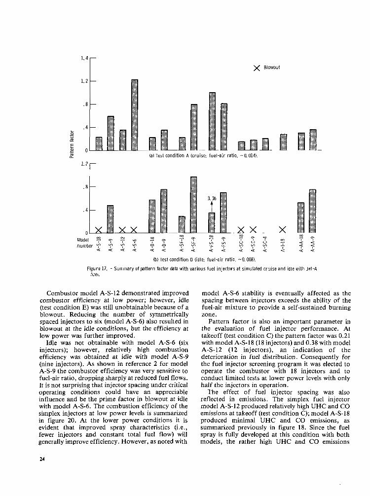
A summary of the pattern factor at cruise and idle (test conditions A and D, respectively) is presented in figure 17. In general the pattern factors at cruise (test condition A) and at takeoff (test condition C) were similar; therefore, since it was not always possible to obtain the required fuel flow with only nine injectors, comparison at cruise is presented for consistency.
The emissions index levels of UHC, CO, NO,, and smoke are summarized for each injector configuration in figure 18 for the two simulated flight conditions of takeoff and cruise (test conditions C and A, respectively). In figure 19 the emissions levels of UHC, CO, and NO, are summarized for each injector configuration at the lower power conditions and idle (test conditions F, G , H, and D, respectively).
The combustor performance and emissions characteristics are compared for each injector.
Exfect of simplex injector spacing (models A-S-18, A-S-9, A-S-12, and A - S - 6 ) . -As previously discussed in reference 2 and summarized in figure 16, operation with 18 injectors showed a marked deterioration in combustion efficiency as the operating pressure was reduced. The reduction in efficiency and stability was presumed to be due to the deterioration of the fuel spray at low injection pressure. Reducing the number of injectors resulted in a higher fuel pressure for each injector accompanied by improved spray characteristics and increased combustion efficiency. Reducing the number of injectors, however, caused an increase in the pattern factor, as shown in figure 17.
To investigate further the effect of fuel injector spacing, a new combustor faceplate was installed to accommodate 12 symmetrically spaced fuel injectors; it was designated model A-S-12. Combustor models A-S-18 and A-S-12 are similar except for fuel injector spacing. Combustor models A-S-9 and A-S-6 are also similar to A-S-18 and A-S-12, respectively, except that the fuel source is cut off from every other injector. Consequently models A-S-9 and A-S-6 are not directly comparable to models A-S-18 and A-S-12 since the inlet air swirlers concentric with the injector were not blmked and this resulted in a rich- lean sequence for models A-S-9 and A-S-6.
19
I I l l I l l I 1 I l l l l l l l l I

100 - Model 121 0 A-AA-I2
80 -
60 -
40- 2 0 - ;\;- o1 0 (a) Simplex fuel injectors.
Idle = 112 7 Model
8
(c) Spill-flow fuel injectors. 80 - a. Model
0 A-SC-18 0 A-SC-9 A A-SC-4 60 -
40-
20 -
J 0 4w 8W 1200 lX00
n
Model 0 A-D-18 0 A-D-9
c (bl Duplex fuel injectors.
Model
0 A-FS-9 0 A-FS-18
(d) Fan-spray fuel injectors.
r-
Pressure, kPa
I 1 I 0 M
I I 1w 1x) 2oi, 0 50 rob 1M 2w I I
Pressure, psia le) Splash-cone fuel injectors. l f i Impingement fuel injector (model A-1-18).
0 4w 800 1200 16CU Pressure, atm
I I I" I I 0 M loo 150 m
Pressure, psia
(g) Air-assist fuel injectors.
Figure 13. - Emission index of carbon monoxide with reverse-flow combustor operating with various fuel injectors at simulated gas turbine condi t ions wi th Jet A fuel and a nominal fuel-air ratio of ClO14.

20
1 1 5
~~ 5
0
20
0
20
5
0
I 0
Model 0 A-S-12 CI A-S-6
- / Model
0 A-D-18
(a) Simplex fuel injectors. Ib) Duplex fuel injectors.
/o
- - Model
-
-
P I I I (cl Spill-flow fuel injectors. (d) Fan-spray fuel injectors.
Model -
0 A-SC-18
//-o 0 A-SC-9 400 800 1200 1600 0 400 800 1200 1600
- / -
-
u I I I I
Pressure, kPa
u I I I I I % 100 150 200 0 M 1W 1% 200
Pressure, psia ( e ) Splash-cone fuel injectors. (fl Impingement fuel injector (model A-1-18).
-
1 5 1
0 A-AA-18 A-AA-9
r ol
Pressure, kPa
I I I d 0 M 1W 1% 2W
Pressure, psia
(g) Air-assist fuel injectors.
Figure 14 -Emission index of oxides of nitrogen with reverse-flow combustor operating with various fuel injectors at simulated gas turbine conditions with Jet A fuel and a nominal fuel-air rat io of a 014
21

0 I (a) Simplex fuel injectors. Ibl Duplex injector (model A-D-18).
40
r i( 0 / , 1
VI
10
IL, 1 _II I
(cl Spill-flow fuel injector (model A-SF-181. (d) Fan-spray fuel injector (model A-FS-91.
10
%O I I
8M) 12W 16W 400 8W 1200 Pressure, kPa
1600
I I I I I I 50 100 150 2W M 100 150 2W
Pressure, psia
(el Splash-cone fuel injector (model I f ) Impingement fuel injector (model A-SC-18). A-1-18),
0 A-AA-18 0 A-AA-9
1
VI p 20
$00 800 I
1 2 w 16W Pressure, kPa
U! 50 100 150 200
Pressure, psia
(9) Air-assist fuel injectors.
Figure 15. - Smoke number obtained with reverse-flow combustor operating with various fuel injectors at simulated gas turbine condit ions with Jet A fuel and a nominal fuel-air ratio of a OM.
22

x Blowout
(a) Test condition F.
(b) Test condition G.
(c) Test condition H. 100 r-
(d) Test condition 0 (idle; fuel-air
Figure 16. - Summary of combustor efficiency data with various fu wi th Jet A fuel and a nominal fuel-air ratio of 0.014.
ratio, -0.008).
el injectors at simulated gas turbine conditions
.
3
1.2
. a
. 4 0 L c u E c L
g o m a (a) Test condition A (cruise; fuel-air rat io, -0.014).
.8 -
X x x -
[ ........ =$ ,$* <.:.:.::
.:.:.:. ....:.:. :w y.....:
........ .> ..... .= :.:x.:. ..... ~
...... :::::::: ........ ........ ,~ $$$ x<: .:.x: :w: $2 x.:..
........ @ @
x 9 % :.:.:e .*^ ........ "'..
(b) Test cond i t ion D ( id le; fuel-air rat io, -0.008).
F igure 17. - S u m m a r y of pat tern factor data with var ious fue l in jectors a t s imulated cru ise and id le wi th Jet -A fuel.
Combustor model A-S-12 demonstrated improved combustor efficiency at low power; however, idle (test condition E) was still unobtainable because of a blowout. Reducing the number of symmetrically spaced injectors to six (model A-S-6) also resulted in blowout at the idle conditions, but the efficiency at low power was further improved.
Idle was not obtainable with model A-S-6 (six injectors); however, relatively high combustion efficiency was obtained at idle with model A-S-9 (nine injectors). As shown in reference 2 for model A-S-9 the combustor efficiency was very sensitive to fuel-air ratio, dropping sharply at reduced fuel flows. It is not surprising that injector spacing under critical operating conditions could have an appreciable influence and be the prime factor in blowout at idle with model A-S-6. The combustion efficiency of the simplex injectors at Iow power levels is summarized in figure 20. At the lower power conditions it is evident that improved spray characteristics (i.e., fewer injectors and constant total fuel flow) will generally improve efficiency. However, as noted with
model A-S-6 stability is eventually affected as the spacing between injectors exceeds the ability of the fuel-air mixture to provide a self-sustained burning zone.
Pattern factor is also an important parameter in the evaluation of fuel injector performance. At takeoff (test condition C) the pattern factor was 0.21 with model A-S-18 (18 injectors) and 0.38 with model A-S-12 (12 injectors), an indication of the deterioration in fuel distribution. Consequently for the fuel injector screening program it was elected to operate the combustor with 18 iqjectors and to conduct limited tests at lower power levels with only half the injectors in operation.
The effect of fuel injector spacing was also reflected in emissions. The simplex fuel injector model A-S-12 produced relatively high UHC and CO emissions at takeoff (test condition C); model A-S-18 produced minimal UHC and CO emissions, as summarized previously in figure 18. Since the fuel spray is fully developed at this condition with both models, the rather high UHC and CO emissions
24

la1 Test condition C Ilakeoffl.
lbl Test condition A (cruise). Figure 18, - Summary of emissions data with various fuel inieciors ai sa-level takeoff
and cruise inlet conditions with Jet A fuel and a nominal fuel-air ratio of a 014
25

I
(a) Test condition F (low power). 100
x ; a0
.E 4 E y 20
.- S 60 " .-
3
0
120
g loo .- .- E a0
E s a m
60
20 0
147 t
(b) Test condition G (low power).
Figure 19. - Summary of emissions data with various fuel injectors at simulated IOW-POWer conditions (nominal fuel-air ratio, 0.014) and at idle with Jet A fuel.
26

r 100
.:.:.:.
.:.> :.= .:.= 40
20
x:x
.....,. :.:.= ........ ;<<*
8r
120 r
X x
424
f x Blowout
(c) Test condition H (low Dower).
....... 0 .))" .:.:.x * :a .:.:.:, w
....... ;<x :$*
.:.:x.: ........ = z<
x x
(d) Test condition D (idle).
Figure 19. - Concluded.
27

I
lT 90 T
t Model
o A-S-18 0 A-S-12
0 A-S-6 A A-S-9
i 40
400 800 1200 1600 Pressure, kPa
I I 100 1% 200
Pressure, psia
F igure 20. - Summary o f e f fect of s implex pressure- a tomiz ing fue l in jector number densi ty on combus- t ion eff iciency.
indicate that quenching was probably occurring between fuel injectors. This is also evident at cruise (fig. 18(b)). Although the CO level was somewhat higher for model A-S-18, the UHC level was considerably higher for model A-S-12 and would account for the combustion efficiency being lower with model A-S-12 than with A-S-18. At the lower power conditions the effect of fuel injector spray characteristics became dominant as previously discussed (fig. 20). The liner geometry air-entry pattern was established on a 36-injector symmetry to allow for repetitive patterns when operated with 6, 9, 12, or 18 injectors. Consequently a steeper gradient exists between the circumferential lean and rich zones with fewer injectors. A slightly higher NO, emission level was also noted with model A-S-12 than with A-S-18. The smoke produced with models A-S-18 and A-S-12 was moderate, as summarized in fig- ure 18.
Duplex injector models A-D-18 and A-D-9. -A duplex fuel injector improves the spray pattern at low fuel flows by diverting the flow to a smaller orifice for improved atomization. The 18 duplex-injector configuration operated at a higher combustion efficiency than the fixed-orifice model A-S-18, as summarized in figure 16. The efficiency level was 78
percent at 4.1 atmospheres, and at the idle fuel-air ratio of 0.008 (test condition D) the efficiency was reduced to 50 percent. The simplex configuration was inoperable at both of these conditions. With nine injectors (model A-D-9) the combustion efficiency was lower with the duplex than with the simplex.
The pattern factor of 0.22 with duplex injector model A-D-18 was satisfactory at cruise (test condition A), and with only half the injectors the pattern factor increased to 0.36, as summarized in figure 17. As the fuel flow was reduced to represent idle, the pattern factor more than doubled for each of the combustor configurations.
It would have been expected that the combustion efficiency level and the pattern factor would have been somewhat better at idle with the duplex injector. Apparently a well-defined spray could not be obtained with the primary orifice. A poor primary spray could have caused problems. That is, interference with the high-flow spray could have resulted in the reduced combustion efficiency experienced. The potential gains inherent with this technique were not achieved in the program. The difficulty was probably due to the fabrication of the primary orifice and the associated small passages, which also resulted in a rather poor pattern factor, as indicated in table 11.
injectors was also reflected in emissions, as summarized in figures 18 and 19. The emissions characteristics of UHC and CO were similar to the results obtained with the simplex injector configuration. Since both injector types are pressure atomizing, this would be considered reasonable. At takeoff (test condition C) NO, emissions levels with the simplex and duplex injectors were similar; however, at cruise and reduced-power levels the NO, emissions were considerably lower with the duplex injector. In general, improvement in NO, with a two- injector site for the same fuel flow should result in a more uniform spatial fuel distribution and hence a lower NO, emission level. At cruise the NO, emission index was 5 g/kg of fuel for model A-D-18 and 12 g/kg of fuel for model A-S-18.
The smoke number was much higher with the duplex than with the similar configuration with simplex injectors, as shown in figure 18. At cruise the smoke number was 42 with model A-D-18 and 14 with model A-S-18. This increase in smoke, however, can be also attributed to the richer core inherent with the duplex configuration.
Spill-flow fuel injector models A-SF-18 and A-SF-9. -The spill-flow injector was selected to provide good spray characteristics at low fuel flows. The spray is maintained by admitting excessive fuel to the spin chamber in order to maintain the pressure required for atomization and spray characteristics
The relatively poor performance with the duplex .

I
and then bypassing the excess fuel back to the fuel supply. In this manner operating characteristics can be selected to provide a constant fuel pressure over a wide range of fuel flows. As shown in figure 16 a relatively high level of combustion efficiency can be maintained at low-power conditions. An efficiency level of 92 percent was obtained at idle with 18 injectors, and reducing the number to nine resulted in only slight improvement.
The pattern factor with the spill-flow injector (model A-SF-18) was relatively uniform over the entire test range. At cruise (test condition A) a pattern factor of 0.22 was obtained. Even as the fuel flow was reduced to the idle condition the pattern factor did not deteriorate appreciably, and a pattern factor of 0.28 was obtained. With the nine-injector configuration (model A-SF-9) pattern factors from 0.8 to 0.96 were noted. The relative uniform tem- perature distribution over the operating range is attributed to the improved spray characteristics of the injector design for low fuel flows. The magnitude of the poorer temperature distribution with model A-SF-9 as indicated by the pattern factor was somewhat surprising but can in part be attributed to insufficient fuel injector density.
The spill-flow injector can be operated over a fairly wide range of spin chamber pressures for a constant-output fuel flow. However, the combustion efficiency and the pattern factor were relatively insensitive to spin chamber pressure level.
As reflected by high efficiency levels with the spill- flow injector (model A-SF-18) UHC and CO emissions were low, as summarized in figures 18 and 19. The NO, emissions with the spill-flow injector were higher at takeoff (test condition C) than those for the simplex injector (i.e., 16.4 g/kg of fuel as compared with 10 g/kg of fuel). Comparing models A-S-9 and A-SF-9 at the lower power conditions shows that NO, emissions were somewhat less with the spill-flow injector than those obtained with the simplex injector; at idle the index was 2.8 g/kg of fuel with the spill-flow injector and 4 g/kg of fuel with the simplex injector. The lower NO, at idle is probably due to the larger spray angle and smaller droplet size resulting in improved mixing.
The emissions levels were dependent on the fuel injection chamber pressure. The effect on CO and NO, emissions at the simulated cruise values of pressure and temperature are shown for a range of fuel manifold pressures for several values of fuel-air ratio in figure 21 for model A-SF-18.
The CO emission index doubled from about 17.5 g/kg to 35 g/kg of fuel as the fuel manifold pressure was increased from 1379 kPa to 2069 kPa differential for a fuel-air ratio of 0.01. The CO emission index also doubled from about 3 g/kg to 6 g/kg of fuel for a fuel-air ratio of 0.014 as shown in figure 21(a) for
Fuel-air ra t i o
0 0.010 40 0 .012
A .014
x 3 0 ' 0) D c .- c 0 VI VI
.-
.- 5 8
(a) Effect on CO emissions. 15 r
1300 1500 1700 1900 21 00 Spi l l chamber pressure, kPa
I 200 225 250 275 300
Spill chamber pressure, psia
(b) Effect on NOx emissions.
F igure 21. - Effect of spi l l -chamber pressure on emissions character is t ics wi th sp i l l - f low fuel injector model A-SF-18 at test condi t ion A.
cruise inlet temperature and pressure (test condition A). The characteristic trade-off between CO and NO, was evident in the NO, emission index in that NO, was reduced as fuel manifold pressure was increased. However, the NO, emission index was not dramatically reduced at the higher fuel flows (13.4 g/kg to 12 g/kg of fuel at a fuel-air ratio of 0.14, fig.
The emissions levels obtained with the spill-flow injector indicate that an optimum operating curve can be selected for minimum emissions at low fuel flows and that it may be unnecessary to regulate spin- chamber pressure at the higher fuel requirements.
The smoke levels obtained with spill-flow injector model A-SF-18 were rather high (33 at takeoff and 24 at cruise). There was also a tendency for the injector to coke. Coking was first noted after operation at
21(b)).
29

low-power conditions. The comparatively large amount of fuel directed through the injector body probably lowered fuel and metal temperatures and this could have influenced coking. A protective shield could probably be used to wash the surface of the injector with a small amount of combustion air to prevent carbon buildup. In this program, however, the outlet temperature distribution was not affected by coke buildup distorting the fuel spray, as reflected in the observed pattern factor.
Fan-spray fuel injector models A-FS-18 and A-FS-9. -The fan-spray fuel injector as installed in the reference configuration (model A-SF-18) performed poorly at simulated-cruise and low-power conditions. These injectors were designed for a different type of combustor configuration and did not function well with the swirl-stabilized configuration.
It was anticipated that the combustor faceplate should be modified for a fan-spray injection system. Consequently one modification was tested with a redesigned faceplate and designated as model A-FS-9. In this configuration the inlet swirlers were omitted. Provision was made for nine symmetrically spaced injectors in order to take advantage of the potential reduction in fuel system complexity inherent with this injector design. As shown in figure 16 the stability and combustion efficiency were greatly improved at all test conditions, and at idle (test condition D) an efficiency level of 96.5 percent was achieved.
The pattern factor obtained with model 9 was unsatisfactory, as shown in figure 17. With a direct substitution of the fuel injectors in the reference combustor, pattern factors of 0.93 to 3.36 were experienced. With the modified faceplate (model A-FS-9) the pattern factor was reduced to 0.8 at cruise (test condition A) and to 0.71 at idle (test condition D). The combustor liner geometry was fixed for all tests in this program and did not account for a radical change in the fuel injection pattern. It would be expected that improvements in pattern factor could be achieved by considering the unique capabilities and requirements of the fan-spray system in designing the liner.
The emissions levels of model A-FS-18 were very high because of the poor combustion efficiency. With model A-FS-9 a marked improvement was achieved through the redesign of the fuel injector faceplate, as summarized in figure 19(d). A UHC emission index of 22 g/kg of fuel and a CO emission index of 79 g/kg of fuel were obtained at the idle condition. The NO, emission index was about 6 g/kg of fuel at idle, which was higher than that for any other injector tested. The high level of N0,indicates that some additional combustion air should have been admitted in the primary zone. The potential of
30
the fan-spray injector in meeting performance requirements with low emission levels appears to be very good, provided allowance is made for air introduction and mixing.
Splash-cone fuel injector models A-SC-18, A-SC-9, and A-SC-4. -The splash cone is an air- blast type of injector that uses the momentum of the incoming air to aid atomization. The injector was adapted from a configuration used in an experimental combustor reported in reference 3. Combustor model A-SC-18 operated with essentially 100 percent efficiency at high pressure. However, at reduced power levels a marked deterioration in performance was evident, as shown in the summary figure 16. At 4.1 atmospheres (test condition H) combustion could not be maintained. With model A-SC-9 operation at 4.1 atmospheres was improved somewhat, but idle (test condition D) could not be operated because of a blowout.
For this configuration one additional fuel injector grouping was also tested (model A-SC-4). Four adjacent injectors were manifolded together to improve the local burning zone and to aid in a more uniform fuel distribution to each injector while keeping injector spacing constant. With this arrangement a combustion efficiency of 98 percent was achieved at the idle condition (test condition D), as shown in figure 16.
The pattern factor obtained with the splash-cone fuel injectors was very good, as summarized in figure 17. At cruise (test condition A) with model A-SC-18 a pattern factor of 0.17 was obtained.
The high combustion efficiency and low pattern factor achieved with this injector system were somewhat surprising. Based on the Sauter mean diameter and the pattern factor, as discussed in the section Fuel Injectors, the splash cone was one of the poorest documented (i.e., Sauter mean diameter to 350 prn and patternator reading deviation to almost 100 percent). At the low fuel flows the pressure drop across the injector was only of the order of 3 kPa. As noted by the drop in combustion efficiency the injector would not function below a minimal fuel flow. However, once this critical flow was exceeded, the characteristics of the system were favorable over the entire range investigated.
The emissions index levels of the splash cone were among the best for the injectors tested. At the takeoff condition with model A-SC-18 the UHC emission index was essentially zero, the CO emission index was 1.6 g/kg of fuel, the NO, emission index was about 13 g/kg of fuel, and the smoke number was about 15 (dropping to 2 at the cruise condition), as summarized in figures 18 and 19. The major problem as previously noted with this injector scheme was lack of stability at low fuel flows, but this deficiency could be eliminated by fuel

manifolding. With model A-SC-4 at idle the UHC emission index was 9 g/kg of fuel, the CO emission index was 68 g/kg of fuel, and the resulting NO, emission index was 2.4 g/kg of fuel. The technique employed to improve efficiency at low power could possibly be adapted to a flight engine without severely jeopardizing reliability or increasing complexity or cost.
The splash-cone injectors were subject to some coking on the back side of the injector cone. As previously noted this injector was adapted from a high-pressure, full-scale combustor (ref. 3). This report also indicated that coking was a problem in the original concept, however, it was shown that it was possible to contour the injector to prevent carbon buildup (ref. 6). It would not seem unreasonable that a similar technique could be used to prevent coking with the model A-SC-18 splash- cone injector. It may also be possible to improve the performance and extend the operating range with 18 injectors by investigating size, number of orifices, air-blast vortex intensity, and the quantity of air used for the air-blast system.
Fuel-impingement fuel injector model A-I-18. -The fuel-impingement injectors used in these tests direct three sets of opposing fuel jets toward each other in an air-blast stream. The combustion efficiency was relatively high over the operating range, as shown in the summary figure 16. At the low-power test condition H the efficiency was 92.5 percent, but as the fuel flow was reduced to idle, blowout occurred. The combustor was not operated in the nine-injector configuration. The pattern factor for model A-1-18 at cruise (test condition A) was 0.27, as indicated in figure 17.
The emissions characteristics of the fuel- impingement injector at the takeoff condition were quite low, a sign of high efficiency, as summarized in figures 18 and 19. The NO, level was somewhat greater than that of many injectors (emission index, 15 g/kg of fuel). The smoke number was 25 at takeoff and dropped to 12.5 at the cruise condition.
The particular technique investigated with this injector was to provide two opposing fuel streams for impingement. In this case three sets of impinging tubes were selected to more widely disperse the fuel. The fuel flow in each tube was intended to provide cooling in order to prevent burning of the injector. In this configuration the injector tip coked because it was too cool. Observation of the injector after operation showed that the coke either broke off or burned off, and thus large chunks did not accumulate. Even so, coking is undesirable. However, because of the demonstrated .high performance, simplicity in design, and low emissions of the impinging jet principle, additional effort may be warranted in its further application. As with the
splash cone the high-performance capability could not have been predicted from simple bench tests because of the poor patternator reading and the large Sauter mean diameter.
Air-assist fuel injector models A-AA-I8 and A-AA-9. -The air-assist injector was not specifically designed for this application; however, the fuel flow range was compatible with the reverse-flow combustor requirements. Air assist is expressed as the ratio of the pressure in the injector to the pressure in the combustor. Pressure ratios from 1.0 to 1.2 were investigated. Combustion efficiency data, as summarized in figure 16, are presented for a ratio of 1.1. The combustion efficiency of model A-AA-18 at 4.1 atmospheres (test condition H) was 94 percent. As the fuel flow was reduced to represent idle (test condition D), the efficiency dropped to 75 percent. For combustor model A-AA-9 an efficiency of 88 percent was obtained at idle.
In general the effect of air-assist pressure ratio on combustion efficiency was insignificant except at the lower power conditions. The combustion efficiencies at idle conditions for combustor model A-AA-I8 were 68, 80, and 75 percent for air-assist pressure ratios of 1.2, I.. 1, and 1.05, respectively.
The pattern factors for the air-assist injectors with combustor models A-AA-18 and A-AA-9 were 0.30 and 0.38, respectively, at cruise (test condition A), as summarized in figure 17. At idle (test condition D) the pattern factor increased to 0.52 for model A-AA-18 and to 0.75 for model A-AA-9, an indication of a deterioration in fuel preparation. A relatively strong dependence on the degree of air assist at low power levels was noted. In figure 22 the effect of various degrees of air-assist pressure ratio on pattern factor is presented. As shown at the higher operating pressure (i.e., greater than 1014 kPa
I - \
Test condit ion O H O G A F OE D A
. 2 Q I I 1 1 0 5 10 15 20
Ni t rogen pressure ra t io , (P in j /p t - 1) 100, percent
F igure 22. -Ef fect o f a i r -ass is t pressure ra t io o n pattern factor for selected test cond i t ions a t nomina l fue l -a i r ra t io of 0.014 w i t h model A-AA-18.
31

differential) the degree of air assist did not appreciably affect pattern factor. As the power level was reduced, the pattern factor had a tendency to peak at a pressure ratio of 1.1 and to decrease as the pressure ratio was further increased.
The degree of air assist also influenced the exhaust emissions levels. In figure 23 the effect of various degrees of air-assist pressure ratio on the emission indices of UHC, CO, and NO, is presented. As shown in figure 23 increasing the air-assist level at the higher operating pressure did not appreciably affect the UHC or CO level. At low pressure (below 8.6
0 5 10 15 20 Nitrogen pressure rat io, (Pinj /Pt - 1) 100,
percent
F igure 23. - Effect of air-assist pressure rat io on emission index for selected test condit ions a t nomina l fue l -a i r ra t io o f 0.014 with node l A-AA-18.
atm) an appreciable effect on CO was noted. It was not possible to determine if a consistent trend of the CO emission index to peak at a pressure ratio of 1.05 would continue at pressures down to 4.1 atmospheres because the CO meter saturated. The UHC index was relatively unaffected by pressure ratio except at 4.1 atmospheres.
The NO, emission index was dramatically affected by air-assist pressure ratio. At the cruise condition the NO, emission index was reduced from 14 g/kg of fuel with no air assist to 3.6 g/kg of fuel for a pressure ratio of 1.2. The reduction in NO, emission was probably due to improved mixing of the fuel and air. For this series of tests the overall fuel-air ratio was less than 0.016; in comparison the design fuel-air ratio was 0.025 for a stoichiometric primary. If insufficient mixing occurs, locally rich zones produce high NO,; more uniform mixing results in a lower equivalence ratio and less NO,. The air-assist fuel injector demonstrated the potential for improved mixing of fuel and air. However, it is doubtful that the complexity involved with the air-assist injector would be warranted except for unique applications.
Concluding Remarks The reverse-flow combustor geometry for this
series was similar for all the injectors tested, so differences in performance can primarily be attributed to injector type. It was shown that even with different injectors fuel-flow range was one of the more important factors influencing performance. To effectively achieve a good fuel spray pattern over a wider fuel-flow range, the number of injectors was varied over the operational range by fuel manifolding. The complexity of fuel manifolding in a practical system could possibly be tolerated if only the idle mode were required. But even €or this case not all injector types performed satisfactorily, as demonstrated.
From an overall standpoint the spill-flow return injector performed fairly well without manifolding. The performance at idle (92 percent combustion efficiency) could possibly be increased by means of improved mixing through geometric changes. One problem that arose during testing was excessive coking on the tip of the injector with a high spill flow, caused by extra cooling of the injector body. Provision can probably be made to prevent or alleviate the recirculation of fuel droplets to the cool tip even with the inherent increase in spray angle at low flows.
The air-blast injector as exemplified by the splash- cone configuration performed very well at simulated inlet engine operating conditions. However, performance was seriously affected at low power. By
32

taking advantage of a fuel manifolding system in which four adjacent injectors supplied the fuel requirements for low power and idle, high performance and low emissions were achieved.
Summary of Results A reverse-flow combustor suitable for a small gas
turbine engine was used to evaluate the effects of fuel injector type and the number density of injectors on combustor performance and emissions. Data were obtained for the following types of injectors: pressure-atomizing, spill-flow, air-blast, and air- assist injectors at pressure and inlet air temperature levels corresponding to simulated idle, cruise, and takeoff conditions of a 16: 1-pressure-ratio engine. The outlet temperature was limited to approximately 1350 K because of the instrumentation. The following results were obtained in this screening program:
1. Major differences in combustor performance and emissions characteristics were experienced with each injector even though the aerodynamic configuration was essentially common to all combustor models except for the fan-spray configuration model A-FS-9. Each injector configuration is summarized as follows:
a. Simplex pressure-atomizing injectors performed well over a limited range, but blowout was encountered at low-power conditions.
b. Duplex pressure-atomizing injectors maintained combustion at all test conditions, but at reduced power and idle the efficiency was low. As a result the unburned hydrocarbon and carbon monoxide levels were high. The system smoked excessively at simulated cruise and takeoff conditions.
c. Spill-flow return injectors performed well over the entire range of test conditions. A 92 percent efficiency was achieved at idle with 18 injectors. The outlet temperature profile was quite good and did not deteriorate as the fuel flow was reduced (i.e., pattern factors of 0.22 at cruise and 0.28 at idle). However, the injector produced a relatively smoky exhaust (i.e., a smoke number of 33 at takeoff).
d. Fan-spray pressure-atomizing injectors were not satisfactory in the reference geometry. A modified combustor faceplate was required. With the
modified geometry, high combustion efficiencies were obtained at low power levels. An idle efficiency of 96.5 percent was demonstrated. However, the fan injector produced a rather high pattern factor - an indication of a need for more extensive modification of the combustor geometry.
e. Splash-cone air-blast injectors performed well over a limited range, but blowout was encountered at low-power conditions. When selective fuel injection manifolding was used to provide for low-power requirements, the splash-cone system performed very well. An idle efficiency greater than 98 percent was demonstrated, pattern factors were the best of those for all injectors (i.e., 0.18 at cruise), and the system produced low smoke (i.e., a smoke number of less than 2 at cruise).
f. Impingement air-blast injectors performed very well over a limited range although blowout was encountered at low-power conditions.
g. Air-assist injectors performed fairly well over the entire operating range, but efficiency was down to 73 percent at idle. The pattern factor was aiso a little high (of the order of 0.3 at cruise). The performance and emissions levels were dependent on the degree of air-assist pressure ratio.
2. The performance obtained with the various fuel injector types could not have been predicted from characteristics obtained by bench testing of air-blast fuel injectors since high performance and low emissions levels were obtained even though high Sauter mean diameter and poor patternation were indicated.
3. Reducing the number of injectors from 18 to 9 generally improved the combustion efficiency at low- power conditions and idle (except for the spill-flow injector), but pattern factor increased.
4. The effect of fuel injector number density was investigated with simplex injectors. As the fuel injector density was decreased from 18- to 6-injector symmetry, low-power combustion efficiency improved. However, the resultant pattern factor at high-power conditions would be intolerable. In addition, stability was affected and resulted in limited operation because of lean blowout.
Lewis Research Center National Aeronautics and Space Administration Cleveland, Ohio, October 31, 1980
33

Appendix - Test Procedure
To assist in the development of small, high- performance combustors, the flow and atomization characteristics of various types of small fuel injectors were investigated. The study was initiated by preparing conceptual design layouts and analytical evaluations of each of 11 different types of pressure- and air-atomizing injectors. Six injectors were selected for experimental study, and from this phase of the program four sets of injectors were fabricated.
The following procedure and calibration were obtained from unpublished data performed under contract NAS3-16817 (Research, Development, and Testing of Small Fuel Atomizers, 1973) by the Lee Company (R. D. Ingebo, NASA Project Manager). A test stand was designed and constructed for testing the injectors. Each injector was experimentally evaluated during the bench testing to determine if the injector fell within a 5 percent flow tolerance limit. All tests were conducted with MIL-F-7204 to simulate jet fuel with a viscosity of about 1.3 centistokes.
In figure 24(a) a schematic of the test stand arrangement is shown for the duplex pressure- atomizing injector. Provision was made to monitor each of the fuel supply lines individually. Tests were conducted over a flow range from 0.38 to 9.45 grams per second (g/sec) of fuel flow for each injector. The duplex injector had a crossover point between the primary and secondary flows at 1.26 g/sec. A typical calibration curve is shown in figure 25(a).
In figure 24(b) a schematic of the test stand arrangement is shown for the spill-flow pressure- atomi&.ng injector. Tests were conducted over a flow range from 0.38 to 9.45 g/sec with varying spill flow selected at 1035 kPa differential. A typical flow calibration curve for the spill-flow injector is shown in figure 25(b).
In figure 24(c) a schematic of the test stand arrangement is shown for the spash-cone and impingement air-blast injectors. Air for the air-blast injector was supplied at 5.5 kPa differential in the ambient test chamber. Fuel flow characteristics are shown in figures 25(c) and (d) for the spash-cone and impingement injectors, respectively.
The fuel spray characteristics as reported in the main text (table 11) were obtained by means of photographs and a patternator. The fuel spray photographs were used to determine cone and droplet size. A high-speed stroboscope with a flash duration of 3 microseconds was used to illuminate the spray. The cone angle was determined by direct measurement, and the Sauter mean diameter was obtained from the following approximation: DSMD= 1 /3 Dm,
where
DSMD Sauter mean drop diameter Dm, size of largest drop in spray photograph
The SMD was approximated by assuming that the droplets were 25 percent larger than the measured size to allow for lack of illumination of the droplet edges. The mathematical definition of Sauter mean diameter defines a size of particle that will have the same surface-volume ratio as the particles in the spray.
Uniformity of the injector spray pattern was measured by using a six-segment patternator. The flow into each segment was collected in a glass tube until one was filled. The reading is obtained by measuring the difference of each tube from the filled tube (an empty tube is indicated by a high-percentage reading).
34

I
fixture Temperature range, 278 to 330 K
(a) Duplex pressure-atomizing injector.
690 kPa 6900 kPa 2069 kPa
7==r-r+ Spill valve
Temperature range, 278 to 330 K
fixture
Bypass valve
Drain reservoir
Reservoir! ~, w, .U r"= Heat exchanger \ , (water cooled)
, -,"""""A .,
(b) Spill-flow pressure-atomizing injector.
5.5 kPa 2069 kPa 3.4 kPa 207 kPa o r n a n o m e t e r 0 gage Q manometer @gage
fixture
278 to 330 K I 8270 kPa
Supply valve
Pressure relief valve
n m
(c) Air-blast injectors.
Figure 24. - Flow schematic of fuel-spray test stand.

loo!”
150
100
50,- -
0 L
(a1 Duplex pressure-atomizing injector. 6 r
5- Spill-port pressure,
4- kPa (psidl
Ib l Spill-flow pressure-atomlzing Injector.
5r
( c ) Splash-cone air-blast injector.
I I 0 2 4 6 8 10 12
Fuel flow. g i s
1 1 1 1 1 1 1 1 1 1 1 0 10 20 30 40 50 60 70 80 90 100
Fuel flow. pph
( d l impingement air-blast injector.
Figure 25. -Typical fuel flow calibration using MIL-F-7024.
36

References
1. Demetri, E. P.; Topping, R. F.; and Wilson, R. P., Jr.: Study of Research and Development Requirements of Small Gas- Turbine Combustors. (ADL-83381-2, A. D. Little, Inc.; NASA Contract NAS3-21980.) NASA CR-1597%, 1980.
2. Norgren, Carl T.; Mularz, Edward J.; and Riddlebaugh, Stephen M.: Reverse-Flow Combustor for Small Gas Turbines with Pressure-Atomizing Fuel Injectors. NASA
3. Ingebo, Robert D.; and Norgren, Carl T.: High Pressure Com- bustor Exhaust Emissions with Improved Air-Atomizing and Conventional Pressure-Atomizing Fuel Nozzles. NASA TN
4. Control of Air Pollution from Aircraft Engines-Emission
TP-1260, 1978.
D-7154, 1973.
Standards and Test Procedures for Aircraft. Federal Register, vol. 38, no. 136, pt. 2, Tues., July 17, 1973, pp.
5 . Procedure for the Continuous Sampling and Measurement of Gaseous Emissions from Aircraft Turbine Engines. Society of Automotive Engineers, Aerospace Recommended Practice 1256, Oct. 1971.
6. Ingebo, Robert D.; and Norgren, Carl T.: Performance and
Nozzles. NASA TM X-3156, 1974. Durability of Improved Air-Atomizing Spash-Cone Fuel
7. Simmons, H. C.: The Prediction of Sauter Mean Diameter for Gas Turbine Fuel Nozzles of Different Types. ASME Paper 79-WA/GT-5, Dec. 1979.
19088-19103.
37

1. Report No. 2. Goverriment Accession No.
NASA TP -1945 4. Title and Subtit le
EFFECT OF FUEL INJECTOR TYPE ON PERFORMANCE AND EMISSIONS OF REVERSE -FLOW COMBUSTOR
7. Author(s)
Carl T. Norgren and Stephen M. Riddlebaugh
9. Performing Organization Name and Address
National Aeronautics and Space Administration Lewis Research Center Cleveland, Ohio 44135
2. Sponsoring Agency Name and Address ~~
National Aeronautics and Space Administration Washington, D. C. 20546
5. Supplementary Notes
a
i 1 1
c 3. Recipient's Catalog No
5. Report Date December 1981
6. Performing Organization Code
505-32-32 8. Performing Organization Report No.
E -556 10. Work Uni t No
11. Contract or Grant No.
13. Type of Report and Period Covered
Technical Paper 14. Sponsoring Agency Code
6. Abstract
The combustion process in a reverse-flow combustor suitable for a small gas turbine engine was investigated to evaluate the effect of fuel injector type on performance and emissions. Fuel injector configurations using pressure-atomizing, spill-flow, air -blast, and air -assist techniques were compared and evaluated on the basis of performance obtained in a full -scale experimental combustor operated at inlet conditions corresponding to takeoff, cruise, low power, and idle and typical of a 16:l-pressure-ratio turbine engine. Major differences in combustor performance and emissions characteristics were experienced with each injector type even though the aerodynamic configuration was common to most combustor models. Performance characteristics obtained with the various fuel injector types could not have been predicted from bench-test injector spray characteristics. The effect of the number of operating fuel injectors on performance and emissions is also presented.
7. Key Words (Suggested by Author(s))
Combustion Helicopter General aviation Fuel injectors
18. Distribution Statement
Unclassified - unlimited STAR Category 07
3. Security Classif. (of this report)
Unclassified 20. Security Classif. (o f this page)
Unclassified 1 I
For sale by the National Technical Information Service, Springfield, Virginia 22161
NASA-Lanpley, 1981

National Aeronautics a‘nd THIRD-CLASS BULK RATE . Postage and Fees Paid
Space Administration . . Space Administration
Washington,. D.C. 20546 / .
. National Aeronautics and
NASA451
. .
Official Business ,
Penalty for Private Use, $300
. .