
Revealing Prior Austenite Grain Boundaries of 4340 Steel
54
Revealing Prior Austenite Grain Boundaries of 4340 Steel Submitted by: Ryan Barrows June 9, 2014 Department of Materials Engineering California Polytechnic State University, San Luis Obispo Conducted in Accordance with Chevron 2014 Ryan Barrows
Transcript of Revealing Prior Austenite Grain Boundaries of 4340 Steel

Revealing Prior Austenite Grain Boundaries of 4340 Steel
Submitted by: Ryan Barrows
June 9, 2014
Department of Materials Engineering
California Polytechnic State University, San Luis Obispo
Conducted in Accordance with Chevron
2014 Ryan Barrows

II
Abstract
Grain growth during austenitization has a negative effect on fatigue strength.
Several methods have been investigated in order to determine an accurate method
of measuring the austenite grain size of 4340 steel. The McQuaid-Ehn method, an
industry standard for evaluating austenite grain size, has been recognized to
produce inaccurate results due to the coarsening of grains during extended
austenitizing. A method utilized for hypoeutectoid steels, outlined by the ASTM-
E112 standard, is investigated to potentially obtain more accurate results by
reducing the duration of austenitizing. Studies regarding effective etching
procedures for revealing austenite grains without austenitizing are also addressed.
Samples are prepared by heat treating to induce temper embrittlement in order to
improve etching at these grain boundaries. Although temper embrittlement is
undesirable for components in service, the process proved to effectively delineate
austenite grain boundaries when etched with a picric acid based reagent. This
method may be utilized to acquire an accurate measurement of austenite grain size
during processing. The picric acid reagent was unsuccessful when applied to the
McQuaid-Ehn and Hypoeutectoid samples. The use of a nital etchant also proved to
be ineffective for the McQuaid-Ehn, Hypoeutectoid and temper embrittlement
methods utilized by this investigation.

III
Acknowledgements
I would like to thank Dr. Trevor Harding for his guidance and consulting throughout
my entire project. I would also like to thank Dr. Blair London for granting me access
to the furnaces. Lastly I would like to thank Christine Ghent and Lisa Rutherford for
helping me acquire the materials utilized within this investigation. I am very
grateful that Chevron has given me the opportunity to conduct this investigation. I
am also thankful for the support I received from my Chevron contact, Sam Mishael.

IV
Table of Contents
Abstract......................................................................................................................................................... II
Acknowledgements................................................................................................................................ III
1 Motivation................................................................................................................................................. 1
2 Introduction............................................................................................................................................. 1
3 Literature Review.................................................................................................................................. 2
3.1 AISI 4340 steel…................................................................................................................................. 2
3.2 Heat Treatment..…………………………………................................................................................. 3
3.2.1 Austenitizing.................................................................................................................................... 3
3.2.1.1 Austenitizing from Pearlite.................................................................................................... 4
3.2.1.2 Austenitizing from Bainite/Tempered Martensite...................................................... 6
3.3 Austenite Grain Size…………………................................................................................................ 7
3.4 Exposing Grain Boundaries........................................................................................................... 7
3.4.1 Etchants.............................................................................................................................................. 8
3.4.2 Tempered-Martensite Embrittlement................................................................................... 9
3.5 Revealing Prior Austenite Grain Boundaries...................................................................... 11
3.5.1 ASTM Methods of Exposing Prior Austenite Grain Boundaries.............................. 11
3.5.1.1 McQuaid-Ehn Procedure....................................................................................................... 11
3.5.1.2 Hypoeutectoid Procedure.................................................................................................... 12
3.5.2 Non-ASTM Methods for Exposing Austenite Grains..................................................... 12
4 Methodology......................................................................................................................................... 13
4.1 Sectioning….............................................................................................................. .......................... 14
4.2 Heat Treating.................................................................................................................................... 15
V
4.2.1 McQuaid-Ehn Treatment.......................................................................................................... 16
4.2.2 Hypoeutectoid Treatment........................................................................................................ 17
4.2.3 Temper Emrittlement………………………............................................................................... 17
4.3 Sample Preparation…………......................................................................................................... 18
4.3.1 Mounting………………………........................................................................................................ 18
4.3.2 Grinding…………………………...................................................................................................... 19
4.3.3 Polishing…………………………..................................................................................................... 19
4.4 Etching…..…………………………....................................................................................................... 20
4.4.1 Nital................................................................................................................................................... 20
4.4.2 Vilella’s Reagent (with Wetting Agent).............................................................................. 20
4.5 Optical Microscopy………………................................................................................................... 21
5 Conclusion and Recomendations................................................................................................. 21
5.1 Results………………………………...................................................................................................... 21
5.2 Discussion…………………………...................................................................................................... 23
5.3 Suggestions.................................................................................................................. ...................... 23
References………………………………………………………………………………………………………... 25
Appendix 1: Thermocouple Data of Applied Heat Treatments……..…………………….... 27
Appendix 2: Sample Preparation Procedures………………………………..........…………….... 29
Appendix 3: Etching Procedures and Safety Precautions…………….…………………….... 33
Appendix 4: Micrographs………………………………………………………………………………...... 40

1 Motivation
The recent failure of a 4340 steel injector quill at Chevron’s facility instigated an
investigation to determine the cause of failure. Analysis revealed that the failed
component was the result of a fatigue-induced fracture. Chevron collected several
injector quills from service to determine if fatigue failure should be a common
concern for these components. Magnetic particle examination and optical
microscopy were utilized to inspect for fatigue cracks. These tests revealed no
presence of cracks. Speculation of fatigue fracture origin shifted towards a potential
variation in austenite grain size.
Austenite grain size contributes to the strength and fatigue life of steel. A
larger austenite grain size is correlated to a decrease in fatigue strength. Therefore,
uncharacteristically large prior austenite grains may exist within the failed
component. In order to determine the optimal grain size for this application,
Chevron must first establish an effective procedure for revealing and measuring
austenite grains of 4340 steel. The ability to precisely determine austenite grain size
will enable Chevron to manipulate the manufacturing processes to generate a
greater level of fatigue strength for 4340 components. Several methods of revealing
prior austenite grain boundaries, PAGB’s, are to be investigated to determine their
accuracy.
2 Introduction
Low alloy medium carbon steels are widely utilized for structural components as a
result of their high strength and toughness. The incorporation of alloying elements

2
provides superior mechanical properties compared to that of plain carbon steel.
Although alloying elements are important, the microstructure is the most significant
factor in establishing mechanical properties of 4340 steel. The major contribution of
these alloying elements is their increased ability to form martensite upon quenching
from the austenite phase.
The final microstructure of steel is determined by the heat treatments
applied during production. Low alloy medium carbon steels are quenched and
tempered for structural materials that require high strength and toughness.
Tempering the martensite microstructure, formed upon quenching, results in the
transformation of the supersaturated phase to ferrite and cementite constituents.
The austenite grain size also contributes to the final microstructure and mechanical
properties of the alloy because martensite formation occurs along these grain
boundaries. Therefore, austenitizing procedures are important to consider in order
to optimize mechanical properties. The decomposition from austenite is well
documented but characterizing the morphology of austenite grains is more difficult.
3 Literature Review
3.1 AISI 4340 steel
4340 steel is a low alloy medium carbon steel, containing 0.38 – 0.43% C, that is
predominantly utilized for structural components. Several common applications of
4340 steel are power transmission pipes, gears and aircraft landing equipment. The
primary alloying elements that are characteristic of 4340 steel are molybdenum,
nickel, and chromium (Table 1). This alloy is selected for structural applications

3
because it features high strength coupled with exceptional resistance to fatigue
when under the heat-treated condition.1
Table I: Chemistry of 4340 alloy steel.1
3.2 Heat treatment
The high strength and fatigue properties of 4340 steel are derived from the applied
quench and temper treatment. The heat treatment procedure that is performed
begins with austenitizing. The alloy is held above the austenitization temperature
(830°C or 1525°F) to obtain a homogenous austenite structure and is then water
quenched to form martensite.1 The super saturated martensite is too brittle for
structural applications so tempering is required to improve toughness.
3.2.1 Austenitization
Studies regarding the austenitization of steels during processing are scarce in
comparison to the investigations concerning the decomposition of austenite.
Information pertaining to the final microstructures and their contributing
characteristics is much more accessible than microstructural properties prior to

4
austenite decomposition. Analysis of the austenite microstructure is difficult
because this phase is only stable at temperatures above 1525°F. The austenitization
procedure is important when considering processing because the final
microstructures nucleate from austenite grain boundaries upon cooling. The grain
size of the final product is heavily influenced by the morphology of austenite grains.
3.2.1.1 Austenitizing from Pearlite
Austenitizing 4340 steel is generally a process that involves transformation from
proeutectoid ferrite and pearlite because the steel obtained is typically air cooled
from austenite during the manufacturing process. Nucleation of austenite takes
place at three locations; the interface of ferrite/cementite structures, line
intersections between platelets and surfaces of pearlite colonies, and points of
intersection between platelets and edges of pearlite colonies (Figure 1).2 These sites
are preferential for nucleation because they do not require as much energy to
achieve the critical radius for nucleation.2

5
Figure 1: Austenite nucleation sites in a plane section of pearlite colonies. (A)
ferrite/cementite interface, (B) intersection between platelets and surfaces of
pearlite colonies, (C) points of intersection between platelets and edges of pearlite
colonies.2
Upon reaching the transformation temperature, ferrite bordering the
cementite plates quickly transforms to austenite. The dissolution of these cementite
plates within the austenite requires a longer period of time. After complete
austenitization, further holding enables diffusion of carbon and substitutional
alloying elements from areas of high concentration to ensure homogenized
austenite grains.3 The duration of hold times are heavily dependent upon the
temperature and starting microstructure (Figure 2). At 925°C, 1700°F, a martensite
microstructure will fully austenitize in ten seconds, while a ferrite microstructure
requires twenty seconds.2

6
Figure 2: Austenitization TTT curves from ferrite, martensite, and bainite
microstructures for 0.25% C low alloy steel.2
3.2.1.2 Austenitizing from Bainite/Tempered Martensite
In the case that the sample is austenitized subsequent to rapid cooling, austenite
will transform from a bainite and/or martensite structure. Heating to the austenite
temperature will allow the diffusion of carbon from the supersaturated martensite.
The carbon bonds with iron forming cementite precipitates. At the austenitizing
temperature austenite grain nucleation will primarily take place along the carbide
and PAGB’s. Austenitizing steels from bainite or tempered martensite produces
acicular and globular austenite grain morphologies. Acicular austenite formation is a
product of an acicular starting microstructure that is heated at a low austenitizing
temperature with slow heating rates. Acicular nuclei also quickly develop to a
globular morphology when heated above the upper critical limit. Initial globular
austenite grain formation is amplified by utilizing elevated austenitizing
temperatures and high heating rates.2

7
3.3 Austenite Grain Size
Austenite grain size directly correlates to the grain size of the final microstructure,
affecting the strength and toughness of the material. Austenite grain boundaries act
as sites for nucleation of ferrite and carbide microstructures during decomposition.
Fine grained ferrite, pearlite, bainite or martensite nucleates from the
decomposition of fine grained austenite.2 When steels initially reach a homogenous
austenitic structure they generally possess a grain size of 0.02 to 0.06 mm in
diameter. Austenite grains with diameters in this range are considered to be “fine”.4
The continuous heating of the homogenous austenite stimulates the kinematic
process of diffusion, creating larger “coarse” grains.
3.4 Exposing Grain Boundaries
Corrosive etching reagents are utilized to reveal steel microstructures. Grain
boundaries are a concentrated source of alloying elements and dislocations that
present a dissimilar chemical potential than the bulk material. The etchant
preferentially attacks these regions, generating fine defects that deflect light
differently. These defects provide a visible contrast at grain boundaries when
conducting optical microscopy.
Although exposing grain boundaries is simple when analyzing the end
microstructure of steel, it is difficult to reveal PAGB’s. Grain boundaries of the newly
formed pearlite, bainite and/or martensite structures interfere when attempting to

8
distinguish the austenite grains. Unique etchants and processes must be utilized in
order to clearly delineate PAGB’s.
3.4.1 Etchants
The most common etchant used for steel is nital, a combination of nitric acid and
ethanol. Nital is effective when revealing the end microstructure of steel but not
PAGB’s. In determining austenite grain boundaries the most common type of
etchant is picric acid. Various modifications of picric acid are utilized to reveal
PAGB’s because etchant selection is unique to the alloy being analyzed. Several
investigations report positive results etching quenched and tempered 4340 steel
with a reagent of 100mL of saturated aqueous picric acid, 6 drops of HCl and 0.5%
of a suitable wetting agent (sodium alkylsulfonate, sodium tridecylbenzene
sulfonate or sodium dodecylbenzene sulfonate).5 This etching reagent is a slightly
modified version of Vilella’s Reagent. Investigations utilizing several variations of
etchants, confirm that PAGB’s in 4340 steel are not effectively exposed without the
addition of HCl and a wetting agent.6 The conclusion of the investigation states that
the sodium tridecylbenzene sulfonate wetting agent is most effective but is costly
and has poor biodegradability. Therefore, it is suggested that the cheaper and
readily biodegradable sodium dodecylbenzene sulfonate be used.5
One study successfully revealed the PAGB’s of quench and tempered 4340
steel with the use of this modified Vilella’s Reagent. The picric acid based etch
visibly displayed the austenite grain boundaries among the final tempered
martensite structure (Figure 3).5 Numerous studies specifically attribute the success

9
of picric acid etchant use for quenched and tempered steels to the preferential
attack of phosphides at the austenite grain boundaries. The concentration of
impurities, including phosphorus, at the PAGB’s is particularly high when samples
are tempered within the embrittlement range.5
Figure 3: Quenched and tempered 4340 steel etched with an aqueous picric acid
solution containing HCl and a wetting agent.5
3.4.2 Tempered-Martensite Embrittlement
Tempered-martensite embrittlement is a diffusion-controlled process regulated by
both the temperature and time of heating. The embrittlement temperature range is
generally avoided during tempering but slow cooling through this region may also
be detrimental to toughness. Tempered-martensite embrittlement is acknowledged
to affect HSLA steels within the temperature range of 200 to 370 °C.7 However, this
range is subject to variation because the embrittlement process is largely dependant
upon the concentration of impurities. Tempering within this region results in a
decreased ductility due to the nucleation of cementite and segregation of impurities
to PAGB’s. Phosphorous and sulfur are considered to be particularly important to

10
the development of embrittlement. Although temper embrittlement negatively
influences the mechanical properties, these heat treatments may be utilized to
increase PAGB delineation. By purposefully inducing temper embrittlement,
accumulation of phosphorus inclusions will increase the vulnerability of PAGB’s to
the picric acid reagent.5 Two temperatures were selected for the tempering process
to account for any potential fluctuation in the temper embrittlement range.
Temperatures of 260°C and 370°C (500°F and 700°F) were selected based upon the
results of 4340 temper embrittlement range investigations (Figure 4).8
Figure 4: Toughness as a function of tempering temperature. The dip in toughness
displays the range of temper embrittlement.8

11
3.5 Revealing Prior Austenite Grain Boundaries
3.5.1 ASTM Methods of Exposing Prior Austenite Grain Boundaries
The ASTM standard E112 outlines several procedures to establish the austenite
grain size of various plain carbon and low alloy steels. The standard provides values
of carbon content to assist in the selection of appropriate testing methods. However,
these values are merely suggestions and may not always expose PAGB’s. Knowledge
of previous heat treatments and present microstructures are important in the
selection of the appropriate method.
3.5.1.1 McQuaid-Ehn Procedure
The McQuaid-Ehn Test, recognized as the general standard for revealing prior
austenite grains, is suggested for steels intended for carburizing and containing less
than 0.25% carbon. However, the standard states it is frequently utilized to evaluate
the microstructure of higher carbon steels that are not subject to carburizing as
well. The test entails carburizing the steel sample at 1700 25 °F (927 14 °C) for a
period of 8 hours or until a hypereutectoid case of approximately 0.050” is formed
on the surface. Slow furnace cooling the sample to or below the austenitizing
temperature is then necessary to enable the precipitation of cementite within the
austenite grain boundaries of the hypereutectoid casing. The surface of the sample
is polished and properly etched to reveal the microstructure.9
12
3.5.1.2 Hypoeutectoid Procedure
This method is recommended for use when investigating low alloy steels of 0.25 to
60% C. Steels of less than 0.35% C are to be heated at 1625 25 °F (885 14 °C) for
30 minutes, while steels above this concentration are treated at 1575 25 °F (957
14 °C). Steels of over 0.40% C are advised to be held at 1340 25 °F (727 14 °C),
subsequent to the initial heating for a period of 10 minutes. Samples are quenched
in water or oil after heating and suitably polished and etched.9
3.5.2 Non-ASTM Method of Exposing Austenite Grains
An investigation of fractured quenched and tempered 4340 steel nut insertions from
the riser of an oil rig attempted to reveal prior austenite grains boundaries without
re-austenitizing.5 Samples were etched in a saturated aqueous picric acid solution
with the addition of HCl (6 drops per 100mL of picric acid solution) and a trademark
wetting agent Nacconol 90G (Chemical composition: 90-93% sodium
dodecylbenzene sulfonate, 5% sodium sulfate, 1% sodium chloride and 1.5%
water). Etching was conducted for seven minutes within an ultrasonic cleaner to
promote agitation. Results from this test displayed definitive austenite grain
boundaries (Figure 3).5 This method is to be replicated to potentially reveal the
actual austenite grain size of the as-received component. This sample may be
utilized as a comparison to establish the accuracy of the ASTM McQuaid-Ehn and
Hypoeutectoid methods.
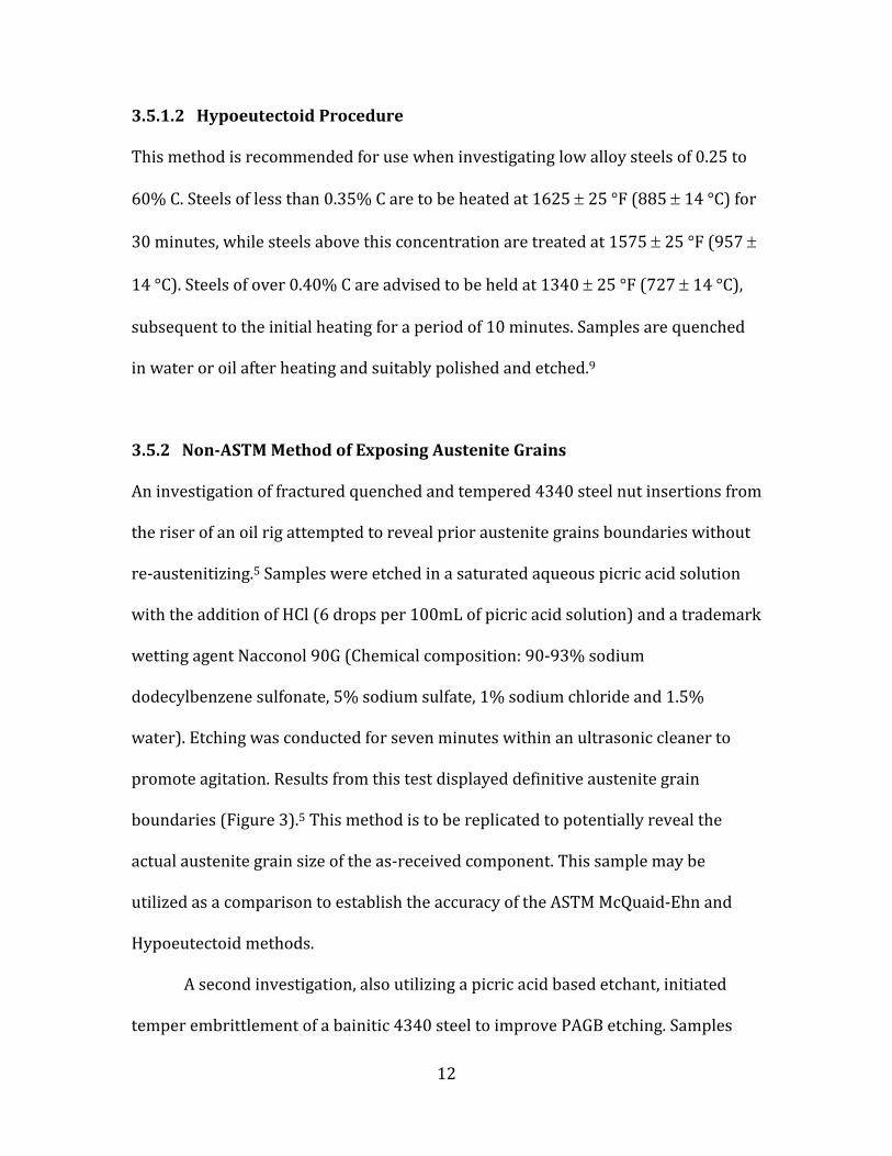
A second investigation, also utilizing a picric acid based etchant, initiated
temper embrittlement of a bainitic 4340 steel to improve PAGB etching. Samples
13
were tempered at 300, 500, 700 and 900°F and etched using the picric solution
containing HCl and Nacconol 90G. Clarity of austenite grains were similar for each of
the established temper treatments (Figure 5). 5
Figure 5: 4340 austenite grains revealed from tempering a bainite microstructure at
300°F.5
4 Methodology
The focus of this project is to determine the accuracy and precision of the McQuaid-
Ehn and Hypoeutectoid methods. Although the McQuaid-Ehn test is regarded as the
industry standard, the ASTM standard recommends a different procedure for low
alloy steels between 0.25-0.6% C. The McQuaid-Ehn procedure has also been
considered inaccurate in many cases.2 Many metallurgists even oppose the use of
the McQuaid-Ehn procedure for determining austenite grain size of quenched and
tempered components. The designated procedure for hypoeutectoid low alloy steels
may be a better alternative to obtain an accurate estimate of austenite grain size.
Another method that may be beneficial is to follow the successful etching
procedures documented by other published investigations. Simply etching with the
modified Vilella’s Reagent may establish a simple procedure for revealing PAGB’s.

14
Etching of the as-received sample would also reveal the actual austenite grain size.
This would eliminate the inaccuracies of produced by the ASTM standard methods.
If etching of the as-received sample is not successful, the effects of tempered-
martensite embrittlement will be investigated. The increased concentration of
phosphorus at the grain boundaries may greatly improve the delineation of
austenite grains. However, this method may only be applied during processing to
accurately measure grain size. The heat treatment applied to induce temper
embrittlement must be conducted on a quenched steel to be effective. The
austenitizing procedure applied before quenching effectively changes the actual
austenite grain size. Although this sample does not reflect the grain size of the
component, it may establish a procedure to reveal PAGB’s during processing.
Accurately determining the austenite grain size of components before they are put
in service would greatly reduce the occurrence of future fatigue fracture.
4.1 Sectioning
The 4340 bar stock, 3.125” in length and 1.125” diameter, obtained from Chevron
was sectioned to produce a sufficient number of samples for the testing procedures
selected. It was determined that each section be cut to 0.2” in length to obtain the
ten samples necessary. A 30-45 HRC rated aluminum oxide rubber bond abrasive
cut off blade was utilized to section one sample for as-tempered, McQuaid-Ehn, and
Hypoeutectoid analysis. The as-received specimen is preserved to establish the
actual austenite grain size of the steel component in service. After sectioning these
three samples, the remaining bar stock was austenitized and quenched to prepare
15
samples for the temper embrittlement method. The rod was austenitized in bulk,
before sectioning 7 individual samples, to ensure a consistent heat treatment for all
specimen subject to temper embrittlement. An aluminum oxide rubber bond
abrasive cut off blade, 45-60 HRC rated, was utilized to section samples for temper
treatments from the bulk quenched bar stock. One quenched sample will also be
preserved to determine whether the temper treatments are necessary. Subsequent
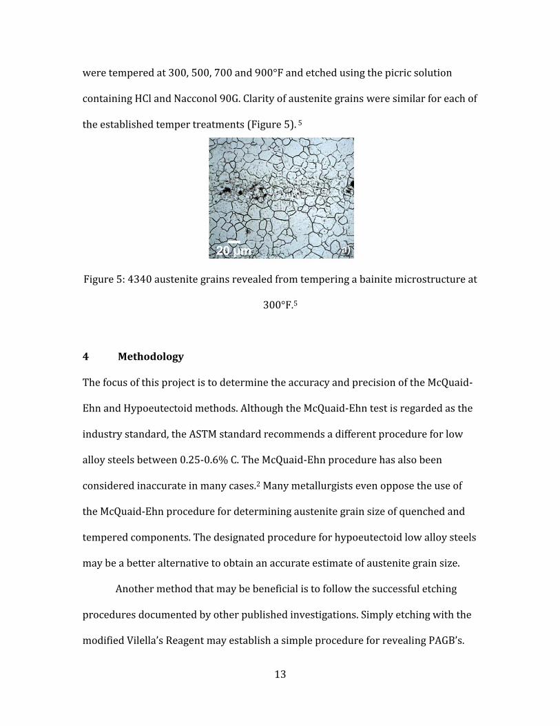
to the heat treatments, each circular sample was sectioned in half, using the 30-45
HRC rated cut off blade, to obtain one sample for nital etching and one for Vilella’s
Reagent etching (Figure 6).
Figure 6: Conformation of sectioning to mount samples for both nital and Vilella’s
Reagent etching.
4.2 Heat Treating
Samples prepared according to the ASTM standard and temper embrittlement
method require a heat treatment process prior to mounting. Thermocouple probes
were utilized to monitor the sample temperature during heat treatments.
Thermocouple data is provided in Appendix 1.

16
4.2.1 McQuaid-Ehn Treatment
This procedure was outsourced to ThermoFusion Inc. because the Cal Poly furnaces
are not capable of providing a carburizing atmosphere. The sample was grinded
following a sequence of 240, 320, 400 and 600 silicon carbide grit grinding sheets
prior to heat-treating. The steel was then austenitized at a temperature of 925C for
9 hours within a carburizing atmosphere to form the 0.05” carburized layer. A
furnace cool was applied to lower the temperature to 775C, just above the
austenitization temperature. Referencing the TTT diagram of 4340 steel, a
controlled cool from 775C to 730C over the period of one hour was specified in
order to nucleate a significant amount of cementite (Figure 7).10 The sample is then
returned to room temperature by a furnace cool. The specified controlled cooling is
crucial for nital to reveal prior austenite grains. Nital preferentially attacks the
cementite regions along the austenite grain boundaries.
Figure 7: TTT curves for 4340 steel.10

17
4.2.2 Hypoeutectoid Treatment
The Hypoeutectoid sample was prepared by austenitizing for 30 minutes at 855C
followed by a furnace cool to 725C. The sample was held at 725C for ten minutes
to allow for significant ferrite nucleation along austenite grain boundaries. Ferrite
enables nital to attack these regions and reveal PAGB’s. The temperature hold was
then followed by a water quench. A high temperature inconel overbraided ceramic
fiber insulated K-type flat probe was attached to the 0.2” thick sample with the use
of a stainless steel fastener. Thermocouple measurements ensured the sample reach
each desired temperature and eliminated any potential disparity due to localized
heat zones within the furnace.
4.2.3 Temper Embrittlement
The temper embrittlement investigation required a total of 7 samples. The
remaining bulk rod, 2.375” in length and 1.125” diameter, was austenitized and
quenched before sectioning to reduce possible heat treatment variation. A high
temperature inconel overbraided ceramic fiber insulated K-type sheathed
thermocouple probe was utilized to verify complete austenitization of the entire
4340 rod. The probe was press fit through the center hole in the rod to establish
reliable contact with the sample. Graphite powder was utilized to fill the center hole
and prevent air from interfering with steel temperature readings. The sample was
austenitized at 845C for 10 minutes and water quenched. Seven samples (0.2” long
and 1.125” diameter) were obtained by sectioning with a rubber bonded Al2O3
abrasive cutoff blade. Three samples were tempered for durations of 30, 60, and 90

18
minutes at 260C and 370C to potentially induce temper embrittlement. One
sample was also preserved as quenched for etching.
The high temperature inconel overbraided ceramic fiber insulated K-type flat
probe was utilized to ensure proper heating during temper treatments. All three
samples were loaded closely together to reduce temperature variation as a result of
furnace location. One sample was removed every 30 minutes and allowed to air
cool.
4.3 Sample Preparation
Subsequent to the applied heat treatments, each sample is identically prepared for
etching and optical microscopy. Standard operating procedures regarding sample
preparation are provided within Appendix 2.
4.3.1 Mounting
Each circular specimen was sectioned to attain two semi-circular samples for both
etching reagents. Samples were mounted in a black glass epoxy powder using the
Buehler Simplimet 2 mounting press. The press is pressurized to 4.2 ksi and heated
for the duration of 10 minutes to cure the epoxy powder. Samples were positioned
to display the semi-circular face, providing the largest surface area for optical
microscopy (Figure 8). However, the McQuaid-Ehn sample is mounted to display the
surface transverse to the carburized layer. This conformation eliminates the
possibility of removing the carburized layer during grinding and polishing.

19
Figure 8: Mounted sample conformation (Left). McQuaid-Ehn Sample (Right).
4.3.2 Grinding
Each mounted sample is subject to a 240, 320, 400, 600 grit grinding sequence
before conducting the polishing steps. The initial grinding step is utilized to remove
all scratches and flaws from sectioning. Samples were advanced to the next grinding
step once all residual abrasions from previous steps were removed. It is necessary
to wash all samples with water between steps to prevent the contamination of
successive grinding papers. Samples were rotated between each step to ensure that
all scratches from previous steps were removed. Grinding was conducted at each
step until all scratches maintain the same directionality.
4.3.3 Polishing
Prior to polishing, each sample must be thoroughly washed to prohibit from
contaminating polishing pads with SiC particles from the grinding papers. The
polishing sequence is composed of two steps. Samples were initially polished on a
gold label polishing cloth with a 6-micron glycol based monocrystalline diamond
20
suspension. Final polish was conducted on a Vel-Cloth polishing pad with a 1-
micron glycol based monocrystalline diamond suspension. Samples are washed with
water and rinsed in ethanol between steps to remove any polishing particles. A blow
dryer is utilized to quickly dry ethanol from the sample face to prevent the
formation of water stains.
4.4 Etching
Safety precautions and procedures for mixing and sample etching are discussed in
detail within Appendix 3. Caution must be taken when handling the hazardous
chemicals utilized in this investigation.
4.4.1 Nital
To produce the 2% nital etchant selected for this investigation, 10mL of 5% nital
was diluted by 15mL of ethanol within a 100mL beaker. Nital etching was conducted
by immerging the sample face in the glass container for 5-10 seconds. The sample is
immediately washed in water after the nital exposure to cease the etching reaction.
An ethanol wash is then utilized to remove excess water from the surface and
provide for a quick dry to prohibit watermarks from forming.
4.4.2 Vilella’s Reagent (with wetting agent)
To prepare this etchant a saturated aqueous picric acid was utilized along with a
small amount of hydrochloric acid and sodium dodecylbenzene sulfonate. The
typical quantity of HCl required for Vilella’s reagent was reduced to reflect the
21
etchant utilized in several other successful reports of PAGB etching.5 The reagent
was mixed by adding 0.1mL of HCl and 0.25g of the powder sodium dodecylbenzene
sulfonate to 25mL of saturated aqueous picric acid.
The etching reagent was poured into a 100mL beaker and placed within an
ultrasonic cleaner. The ultrasonic cleaner agitates the sample, removing corrosive
buildup that may protect the sample surface from the etchant. Samples were
immersed within the etching reagent for 7 minutes. The samples are washed with
water upon removal to cease the etchant attack. Samples are then lightly polished
with the 1-micron solution to remove corrosive buildup and final microstructures
that may distract from the austenite grain boundaries. The etching and back
polishing cycle was conducted 3 times to further establish these grain boundaries
before capturing micrograph images.
4.5 Optical Microscopy
Micrograph images of each sample were taken by a Leica optical microscope.
Micrographs were obtained at magnifications of 1000X to provide an accurate
representation of the grain size in each sample.
5 Conclusion and Recommendations
5.1 Results
The micrographs obtained from the ASTM E112 standard samples of both etchants
did not effectively reveal the prior austenite grains. Etchings of the as-received and
quenched samples were also unsuccessful. The only procedure that effectively
22
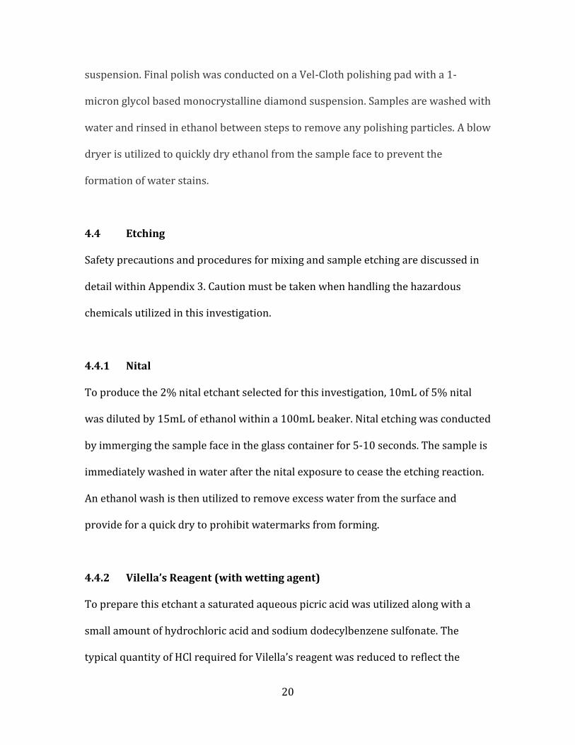
delineated austenite grain boundaries was the modified Vilella’s Reagent etching of
the temper embrittled samples (Figure 9). All temper embrittled samples, both heat
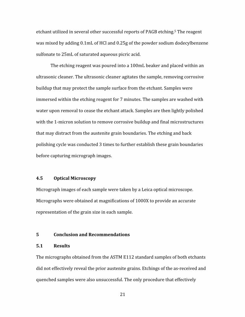
treated at 260C and 370C, successfully revealed the austenite grains. The light 1-
micron back polish also proved to be crucial after etching with the picric acid based
reagent (Figure 10). Micrographs obtained at 1000X magnification for each etching
procedure may be seen in Appendix 4.
Figure 9: Quenched and tempered samples etched with modified Vilella’s Reagent.
60 minute temper at 260C (left) and 370C (right).
Figure 10: Pre-back polished (left) and post-back polished (right) Vilella’s Reagent
etched micrographs.

23
5.2 Discussion
Without being able to quantify the grain size of the ASTM standard samples, no
comparison could be made to establish the accuracy of these methods. The failed
etching of the as-received sample also did not allow for measurement of the actual
austenite grain size. Although the temper embrittlement method effectively
displayed the austenite grain boundaries, quantifying the size of these grains would
not contribute to this investigation. The re-austenitizing step required during the
preparation of these samples effectively changed the austenite grain size from the
sample as it was received. Determining the variation of grain size resulting from this
austenitizing step was also not capable because the austenite grains of the as-
received sample were not visible.
5.3 Suggestions
The temper embrittlement method is not capable of determining the austenite grain
size of components in service but it may be utilized to reveal PAGB’s during
processing as a method of quality assurance. Preparation of 4340 steel components
begins by austenitizing and water quenching. Following the water quench, the steel
is tempered to increase the toughness and resistance to fatigue. To optimize these
mechanical properties it is necessary to closely monitor the growth of austenite
grains during the austenitizing process.
Incorporating the temper embrittlement method during manufacturing
would provide a system to evaluate and optimize austenite grain size and fatigue
strength of injector quills. This process would involve sectioning a small sample

24
from the quenched bulk rod stock before applying the final temper for service. This
sample would be tempered within the embrittlement range, 260-370C, verified by
this investigation. The sample would then be etched by the modified Vilella’s
Reagent that was confirmed effective for revealing PAGB’s. If the austenite grains
are within specification, the quenched steel rod may be tempered for service. If
austenite grains are larger than desired for the application, the 4340 rod may be re-
austenitized under a revised austenitizing procedure to obtain finer grains.
Reducing the temperature or time of the austenitizing procedure will reduce the
amount of growth exhibited by the newly nucleated austenite grains.

25
References
1. "AISI 4340 Alloy Steel." The A to Z of Materials. AZoM, 7 Sept. 2012. 20 Nov. 2013.
<http://www.azom.com/article.aspx?ArticleID=6772>.
2. Sinha, Anil Kumar. "Chapter 8: Austenite." Ferrous Physical Metallurgy. Boston:
Butterworths, 1989. Page: 309-314.
3. Totten, George E. "Hardening by Formation of Martensite." Steel Heat Treatment:
Metallurgy and Technologies. Boca Raton, FL: Taylor & Francis, 2007. Page: 355-58.
4. Brooks, Charlie R. "Austenization of Steels." Principles of the Heat Treatment of Plain
Carbon and Low Alloy Steels. Materials Park, OH: ASM International, 1996. Page: 216.
5. Vander Voort, George F. "Revealing Prior-Austenite Grain Boundaries in Heat
Treated Steels." Failure Analysis & Archeometallography Consulting. Vander Voort
Metallography, 27 Nov. 2013.
<http://www.georgevandervoort.com/metallography/specific/iron-and-steel-
specific/20001306-revealing-prior-austenite-grain-boundaries-in-heat-treated-
steels-article.html>.
6. Vander Voort, George F. "Microstructure." Metallography, Principles and Practice.
Materials Park, OH: ASM International, 1999. 218-23.
7. Hochgraf, Fred. "Embrittlement of Steels." Embrittlement of Steels. New Hampshire
Materials Laboratory Inc., 1 Apr. 2007. Web. 3 Feb. 2014.
<http://www.nhml.com/embrittlement-of-steels.cfm>.
8. Herring, Daniel H. "Toughness." Industrial Heating. BNP Media, 3 Dec. 2010. Web. 24
May 2014.
<http://www.industrialheating.com/articles/89754-toughness>

26
9. ASTM Standard E112-12, January 2013, "Standard Test Methods for Determining
Average Grain Size," ASTM International, West Conshohocken, PA, 2013, DOI:
10.1520/E0112-12, www.ASTM.org
10. De Lima, Andre, Luiz S. Gambaro, Milton V. Junior, and Elesandro A. Baptista. "The
Use of Cylindrical Grinding to Produce a Martensitic Structure on the Surface of
4340 Steel." Journal of the Brazilian Society of Mechanical Sciences and Engineering.
Scientific Electronic Library Online, Aug. 2012. Web. 24 May 2014.
<http://www.scielo.br/scielo.php?script=sci_arttext&pid=S1678-
58782011000100005>

27
0
200
400
600
800
1000
1200
1400
1600
1800
21
:41
21
:46
21
:51
21
:56
22
:01
22
:06
22
:11
22
:16
22
:21
22
:26
22
:31
22
:36
22
:41
22
:46
22
:51
Te
mp
era
ture
(°F
)
Time (Hour:Minute)
Hypoeutectoid Method Heat Treatment
0
200
400
600
800
1000
1200
1400
1600
18001
8:5
3
18
:58
19
:03
19
:08
19
:13
19
:18
19
:23
Te
mp
era
ture
(°F
)
Time (Hour:Minute)
Austenitize and Quench Heat Treatment
Appendix 1: Thermocouple Data of Applied Heat Treatments

28
0
100
200
300
400
500
600
21
:26
21
:31
21
:36
21
:41
21
:46
21
:51
21
:56
22
:01
22
:06
22
:11
22
:16
22
:21
22
:26
22
:31
22
:36
22
:41
22
:46
22
:51
22
:56
23
:01
23
:06
23
:11
23
:16
23
:21
23
:26
23
:31
23
:36
23
:41
Te
mp
era
ture
(°F
)
Time (Hour:Minute)
500°F Temper Heat Treatment
0
100
200
300
400
500
600
700
800
22
:22
22
:27
22
:32
22
:37
22
:42
22
:47
22
:52
22
:57
23
:02
23
:07
23
:12
23
:17
23
:22
23
:27
23
:32
23
:37
23
:42
23
:47
23
:52
23
:57
0:0
2
0:0
7
0:1
2
0:1
7
0:2
2
0:2
7
0:3
2
0:3
7
0:4
2
Te
mp
era
ture
(°F
)
Time (Hour:Minute)
700°F Temper Heat Treatment

29
Appendix 2: Sample Preparation Procedures Sectioning - LECO MSX-250A
1. Place the work piece onto the table and lock in place by pushing the clamp up
against the sample and push the rods down to secure the work.
2. Adjust the sprayers so that they shoot water onto the tip of the blade, but far up
enough that water still hits the blade while the blade wears down during cutting.
3. While the MACHINE IS OFF, leave the safeguard up and bring the blade down, as if
making the cut, to make sure that the blade is aligned correctly.
4. Lower the safeguard and turn the main power switch to the | position.
5. Push the CONTROL ON button.
6. Push the BLADE ON button.
7. Make sure that the machine speed is slower than that of the established cut-off
blade speed by checking the gauge labeled BLADE SPEED.
8. Once the blade speed is set, turn the PUMP OFF/ON switch to the right to turn on
the water.
9. Slowly bring down the handle to the work and begin cutting.
10. If the motor slows down noticeably during cutting, ease up on the handle and slow
your cutting speed.
11. When finished cutting, turn off the coolant before stopping the wheel by switching
the PUMP OFF/ON switch to the left.
12. Turn off the blade by pushing the BLADE ON button.
13. Push the CONTROL OFF button.
14. Open the safe guard, remove your work, turn off the main power switch if done and
leave the guard up. Wipe down the table and clamps.

30
Furnace
1. Ensure that all safety components of the furnace, such as automatic shut-off valves,
air switches, and exhaust fans are functional before heating.
2. Check that the quench bath contains enough water to effectively quench the sample.
3. Properly attach the thermocouple probe to the sample to monitor the temperature
of the sample.
4. Set up the data logger to record temperature readings.
5. Program the furnace to the desired temperature.
6. When the furnace reaches the set temperature insert the samples.
Always wear a face shield, safety glasses, gloves and heat-resistant protective
clothing when opening the furnace.
Use the proper tongs to insert and remove samples from the furnace.
7. When the heat treatment is complete, remove the sample and submerge it within
the water bath and stir vigorously.
Mounting - SimpliMet2s
1. Use the lever to raise the shaft.
2. Place sample on the stage.
3. Lower the stage using the release pressure valve located at the base of the machine
and tighten the release pressure valve again.
4. Place the sample into the shaft of the machine followed by a scoop of epoxy powder.
5. Screw the top onto the shaft.
6. Raise pressure to the red 1.25” marker on the pressure gauge.

31
7. Turn on the heating element and place it onto the shaft. Wait 10 minutes for the
epoxy powder to set.
8. With hand protection, remove the heating element from the shaft and place the
cooling element over the shaft for fastest removal of sample. Wait 10 more minutes.
9. Release the pressure using the release pressure valve. Unscrew and remove the top.
If you can unscrew the top but cannot remove it then use the stage to push the top
out of the machine.
Grinding – Kalamazoo belt grinder and abrasive strips
1. To change the abrasive belt of the grinder release the clasps on both sides of the
grinder.
2. Using a 9/16” hex nut ratchet, loosen the bolt that lies on the inside of the right
wheel until the bolt no longer rests upon the flat surface above. Do NOT remove the
used belt yet.
3. Apply pressure to the bottom of the loop of the used belt in order to bring the
wheels closer together and lock into place by rotating the small metal tab 90.
4. Remove the used belt and throw it away. Replace with the new abrasive belt.
Abrasive belts will be selected specifically for each sample.
5. Press down to release the tab and allow the wheels to move apart so that the belt is
taut.
6. Tighten the bolt until the top nut is up against the plate above.
7. Quickly turn the grinder on to ensure that the belt does not drift during operation. If
the belt drifts towards you while standing in front of the open grinder, tighten the

32
nut. If the belt drifts away from you loosen the nut. Close the grinder when finished
and return any tools used.
8. Before touching the sample to the abrasive belt, turn the belt grinder and the water
valve on.
9. Tightly hold the sample while applying light pressure to the abrasive belt.
10. Clear the metal surface of any overlaying phenolic mounting material before moving
to the abrasive strips.
11. Turn on the water to dampen the abrasive strips.
12. The grinding strip sequence should start on the lowest grit abrasive, higher than the
grit used on the belt grinder, and continue towards the finest grit available.
13. Apply light pressure and push the sample upwards on the abrasive strip, keeping
the sample as flat as possible.
14. Wash the sample with water between strips to reduce contamination.
15. The sample should be rotated 90 between strips to visibly demonstrate that the
present grinding has removed all prior abrasions.
16. After the abrasive strip sequence is finished, wash the sample with ethanol to
minimize the effects of corrosion from the water lubricant used during grinding.
Polishing
1. Place the adhesive polishing pad on to the platen.
2. Turn polishing device on.
3. Apply the desired suspension solution to the pad.
4. Holding tightly, place the sample face down on the rotating polishing pad and apply
light pressure.

33
5. Slowly rotate the sample around the polishing pad, counter to the wheel rotation.
6. Wash the sample with ethanol before moving to another pad to avoid contamination
of polishing cloths.
Appendix 3: Etching Procedures and Safety Precautions
Etching Safety Protocols
1. Always wear splash goggles, nitrile gloves, lab coat, long pants and closed toed shoes
while handling etching reagents.
Avoid physical contact with reagent components.
o If chemicals contact skin or eyes continuously flush eyes with water for at
least 15 minutes, seek medical attention.
o If gloves become soiled remove immediately and discard in garbage. Wash
any exposed skin thoroughly for at least 15 minutes, seek medical attention.
o Wash soiled clothing prior to reuse.
2. Mix all etching reagent chemicals within a 100mL glass beaker under the fume hood.
Avoid inhaling the toxic vapors from etching components.
Utilize a 10mL and 50mL glass graduated cylinder for accurate measurement of
solutions.
Utilize a plastic measuring boat to properly measure solid components.
Add measured solutions to the 100mL glass beaker selected for etching samples.
Always add reagents to the solvent.

34
o When mixing the picric acid etching reagent always add saturated
aqueous picric acid before concentrated hydrochloric acid and sodium
dodecylbenzene sulfonate.
Clearly label all etchants and store in a sealed glass container at room
temperature away from humidity, direct sunlight and environments that may
vary in temperature.
o Utilize an ethanol squirt bottle to clean all glassware before Nital etching.
o Utilize a water squirt bottle to clean all glassware before picric acid etching.
Use squirt bottle to also dissolve any solid picric particulates that may form
during mixing and etching.
Note: Dry picric acid is shock sensitive and may detonate.
Avoid placing caps on soiled surfaces during mixing. Reseal reagent containers
quickly after use to minimize exposure to air and humidity.
Etchants should be used as soon as possible and should never be used past the
estimated shelf life.
3. Conduct picric acid etching procedures behind a blast shield that will be placed
within the fume hood.
4. After etching, pour the remaining reagent mixture in the etchant’s respective waste
container.
A polyethylene funnel will be utilized to effectively pour waste into the waste
container.
The Nital and picric acid reagents will be stored in separate waste containers.
Chemical Hazards

35
1. Nital (Nitric acid and ethanol)
Must be stored in solution of less than 2% nitric acid.
o Corrosive: Liquid and vapor may cause burns to body tissue.
o Avoid exposing Nital to other chemical agents. Contact with other materials
may cause fire.
o Nital is harmful and potentially fatal if swallowed or inhaled.
2. Ethanol
Flammable: keep away from heat, sparks and open flame.
o Ethanol is highly flammable and vapor may form combustible mixtures
within the air.
3. Picric acid
Potentially explosive if dry: The greatest concern regarding the picric acid
solution is the drying and formation of solid particles. Picric acid may explode
under shock in the solid state.
o Solid crystals are most likely to form on the threads of the container. If solid
picric acid is encountered, carefully spray the affected area with the water
squirt bottle or submerge in water to dissolve the solid. Promptly notify the
Environmental Health and Safety department of the presence of the
detonable substance.
Picric acid solution and vapor may cause severe burns to body tissue.
Avoid exposing picric acid to other chemical agents.
Picric acid is harmful and potentially fatal if swallowed, inhaled, or absorbed
through the skin.

36
4. Hydrochloric acid (HCl)
Corrosive: HCl liquid and vapor may cause severe burns to body tissue.
Avoid exposing hydrochloric acid to other chemical agents.
HCl is harmful and potentially fatal if swallowed, inhaled, or absorbed through
the skin.
5. Sodium dodecylbenzene sulfonate
Avoid swallowing, inhaling and contact with skin.
o Ingesting the powder may be harmful.
o Contact with skin will cause minor irritation.
Materials List
100mL beaker
50mL graduated cylinder
10mL graduated cylinder
Polyethylene funnel
Polyethylene rinsate vessel
Nitrile gloves
Tongs
Hot air blow dryer
Fume hood
Ultrasonic cleaner
10mL Nital etchant (5% concentrated nitric acid in ethanol)
1L Ethanol squirt bottle
1 Nital waste container

37
25mL Saturated picric aqueous solution
0.1mL Hydrochloric acid
0.25g Sodium dodecylbenzene sulfonate
1L water squirt bottle
1 Picric acid waster container
Etching Procedures
1. Preparing Nital
Place all components of the Nital etching reagent along with an ethanol squirt
bottle under the fume hood.
Clean the rinsate vessel, 50mL graduated cylinder and 100mL beaker before use.
o Cleaning will be conducted with the ethanol squirt bottle.
o Soiled ethanol will be poured into the Nital waste container with the use of
the polyethylene funnel.
Measure 15mL of ethanol in the 50mL graduated cylinder and pour into the
100mL beaker.
Measure 10mL of 5% Nital in the 50mL graduated cylinder and add to the
beaker, diluting the solution to 2% nitric acid.
2. Nital etching
Immerse one of the 10 samples in the beaker of Nital for 5-10 seconds.
Upon removal, clean the sample with ethanol over the rinsate vessel and blow
dry.
o Each sample will be cleaned with 10mL of ethanol from the ethanol squirt
bottle.

38
Repeat for each of the 10 samples.
Transfer the soiled ethanol from the rinsate vessel and the remaining reagent
from the 100mL beaker to the Nital waste container.
o Utilize the polyethylene funnel to pour the waste into the waste container.
3. Preparing picric acid reagent
Place all components of the picric acid etching reagent along with a water squirt
bottle under the fume hood.
o Ensure that the ethanol squirt bottle is removed from the fume hood.
Label the picric acid container with the date opened and record the amount used
during each etching process.
The rinsate vessel, 100mL beaker, 50mL and 10mL graduated cylinder will be
cleaned with water from the water squirt bottle.
o Soiled water will be transferred to the picric acid waste container with the
use of the polyethylene funnel.
Measure 25mL of 1.2% saturated aqueous picric acid in the 50mL graduated
cylinder and transfer to the 100mL beaker.
Measure 0.1mL of hydrochloric acid in the 10mL graduated cylinder and add to
the beaker.
Measure 0.25g of powder sodium dodecylbenzene sulfonate in a plastic
measuring boat and add to the beaker.
o Dispose of the plastic measuring boat in the garbage.
4. Picric acid etching
Add water to the ultrasonic cleaner.

39
Place the 100mL beaker containing the picric acid reagent within the ultrasonic
cleaner.
o Ensure that the water is well below the top of the beaker so water does not
dilute the reagent.
o Observe the picric acid solution to monitor the formation of any solid picric
acid.
Douse any solid picric acid with water from the water squirt bottle to
dissolve the particles.
Utilize tongs to insert one sample into the 100mL beaker.
o Tongs will reduce the possible physical exposure to the picric acid reagent.
Etch each sample individually for 7 minutes.
Tongs will also be used to remove the sample from the etchant.
Wash the sample with 10mL of water from the water squirt bottle above the
rinsate vessel.
Blow-dry the sample.
Repeat the picric acid etching procedure for each of the 10 samples.
Transfer remaining etching reagent from the 100mL beaker, and fluid utilized
for washing to the Picric acid waste container using the polyethylene funnel.
When the project is complete Tom Featherstone (Environmental Health and
Safety) will be contacted to arrange for the proper disposal of the remaining
picric acid aqueous solution and the picric acid etchant waste container.

40
Appendix 4: Micrographs
Nital Etched Samples (1000X magnification)
Microstructure of as-received sample.
Microstructure of McQuaid-Ehn sample.

41
Microstructure of Hypoeutectoid sample.
Microstructure of quenched sample.

42
Microstructure of quenched and tempered sample (260C for 30 minutes).
Microstructure of quenched and tempered sample (260C for 60 minutes).

43
Microstructure of quenched and tempered sample (260C for 90 minutes).
Microstructure of quenched and tempered sample (370C for 30 minutes).

44
Microstructure of quenched and tempered sample (370C for 60 minutes).
Microstructure of quenched and tempered sample (370C for 90 minutes).
45
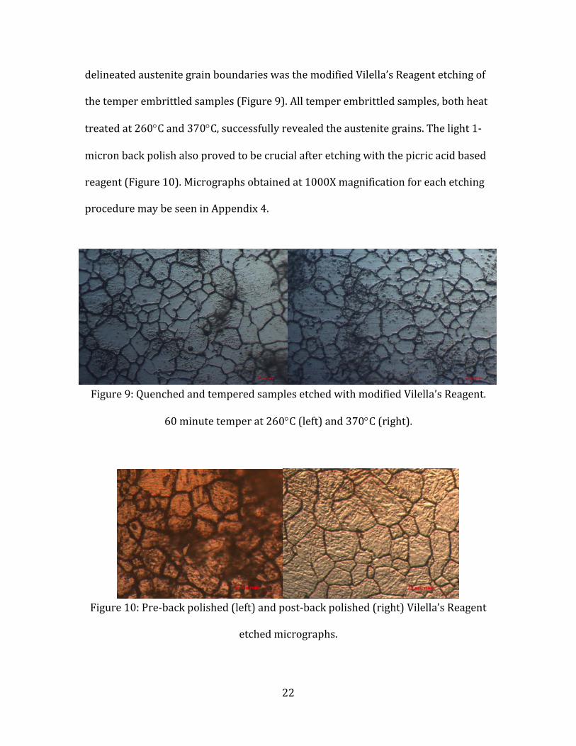
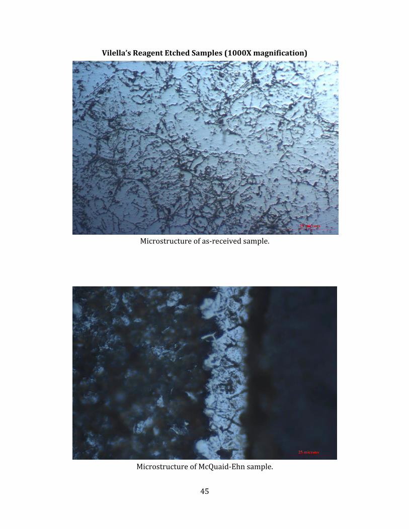
Vilella’s Reagent Etched Samples (1000X magnification)
Microstructure of as-received sample.
Microstructure of McQuaid-Ehn sample.

46
Microstructure of Hypoeutectoid sample.
Microstructure of quenched sample.

47
Microstructure of quenched and tempered sample (260C for 30 minutes).
Microstructure of quenched and tempered sample (260C for 60 minutes).

48
Microstructure of quenched and tempered sample (260C for 90 minutes).
Microstructure of quenched and tempered sample (370C for 30 minutes).

49
Microstructure of quenched and tempered sample (370C for 60 minutes).
Microstructure of quenched and tempered sample (370C for 90 minutes).