Water Solutions for Downstream Oil & · PDF fileCPI (Corrugated Plate Interceptor Systems)
Upload
truonghanhCategory
view
215download
0
Trabajo técnico presentado en el congreso CHISA 2000, Agosto ’00 – PRAGA – Rep. CHECA.
REVAMPING OF A TOPPING WITH
STRUCTURED PACKING
SPEKULJAK(*), Zvonko, MONELLA, Horacio(*), CAROSIO, Eduardo(#), LARA, César Javier(#).
(*) SIT Ingeniería SRL, San José 2832, 3000 Santa Fe. Argentina. TE/Fax 0054 342 4551637. Email [email protected] (#) REPSOL YPF S.A., Refinería Luján de Cuyo. Mendoza. Argentina. 1.- INTRODUCTION. The revamped Topping (Topping III at the Distillery) processes 6,500 m3/d. The column is 3,57 m. in diameter, and it was originally designed with conventional gas-liquid plates. The Plant was shutdown in December ’98 to make the modifications. The fractionation capacity of the Column was poor. The Reduced Crude contains too much light fractions (35 % at 360 ºC). The Virgin Gas Oil was a black product, + 8 ASTM 1500, even without steam injection.
Live steam was not possible to inject at the bottom, because of the presence of black color in the superior distillates (Gas Oil, Kerosene), which was produced by the entrainment of asphalt particles from flash chamber. The poor gas wash in the Slop Wash zone was not so effective to retain the carbon. 2.- TARGET OF THE REVAMP. The targets proposed for the Revamp were, a) Reduce the light components at the bottom stream, so that the Reduced Crude improves its distillation curve, and consequently, the Vacuum Tower and the Isomax unit operations improve. b) Increase the distillate rates, specially the Gas Oil,
Pag. 1 de 1

c) Reduce the asphalt content in the middle distillates, in a significant amount.
Pag. 2 de 2
Pag. 3 de 3
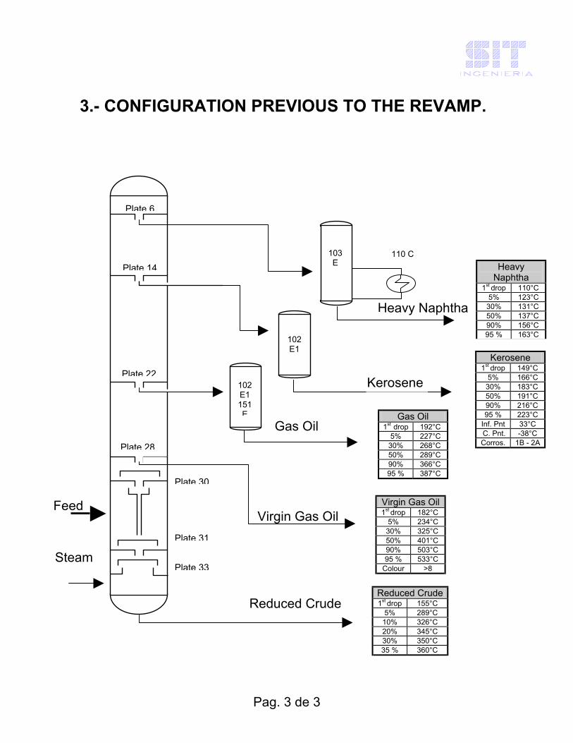
3.- CONFIGURATION PREVIOUS TO THE REVAMP.
Virgin Gas Oil
Heavy Naphtha
Heavy Naphtha
1st drop 110°C 5% 123°C
30% 131°C 50% 137°C 90% 156°C 95 % 163°C
Gas Oil
103 E
Plate 6
Plate 14
Plate 22
Plate 33
Plate 30
Plate 31
Plate 28
Reduced Crude
110 C
102 E1 151 E
102 E1
Kerosene
Virgin Gas Oil 1st drop 182°C
5% 234°C 30% 325°C 50% 401°C 90% 503°C 95 % 533°C
Colour >8
Gas Oil 1st drop 192°C
5% 227°C 30% 268°C 50% 289°C 90% 366°C 95 % 387°C
Kerosene 1st drop 149°C
5% 166°C 30% 183°C 50% 191°C 90% 216°C 95 % 223°C
Inf. Pnt 33°C C. Pnt. -38°C Corros. 1B - 2A
Feed
Steam
Reduced Crude 1st drop 155°C
5% 289°C 10% 326°C 20% 345°C 30% 350°C 35 % 360°C
4. THE NEW CONFIGURATION. The Revamping made involves the Column Flash zone, the Slop-wash bed and the Bottom section.
An appropriate flow distributor, to segregate and to spread the liquid and the vapor phases, was arranged in the Flash zone.
In the Slop-wash a composed bed was installed, part of it a
conventional Structured Packing and part of it an inertial drop capture proprietary Structured Geometry.
A suitable liquid distributor was installed above this bed. The column bottom was filled with a proprietary Structured Grid. A chimneys tray was the actual liquid distributor above the grid bed. The live steam was injected in the bottom by mean of a gas distributor.
Pag. 4 de 4

Pag. 5 de 5
4.2.- AFTER REVAMP.
Gas Oil
Virgin Gas Oil
Plate 6
Plate 14
Plate 22
Structured Grid Bed
Chimney Tray Liquid Collector
Feed stream Distributor
Weir Liquid Distributor Structured Packing Bed
Steam Distributor Steam
Feed
Plate 28
Reduced Crude
102 E1 151 E
110 C 103 E
Kerosene
Heavy Naphtha
Reduced Crude 1st drop 180°C
5% 332°C 10% 360°C
Virgin Gas Oil 1st drop 179°C
5% 275°C 30% 400°C 50% 450°C 90% 517°C 95 % 549°C colour < 3
Gas Oíl 1st drop 215°C
5% 244°C 30% 272°C 50% 294°C 90% 354°C 95 % 389°C
Heavy Naphtha
1st drop 107°C 5% 123°C
30% 132°C 50% 139°C 90% 158°C 95 % 188°C
Kerosene 1rst drop 155°C
5% 178°C 30% 188/°C 50% 195°C 90% 216°C 95 % 240°C
Inf. Pnt 48°C C. Pnt. -53°C Corros. 1A
PROJECT “BOTTOM REVAMPING”
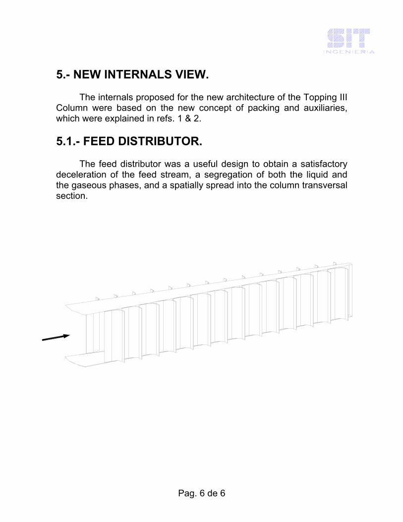
5.- NEW INTERNALS VIEW. The internals proposed for the new architecture of the Topping III Column were based on the new concept of packing and auxiliaries, which were explained in refs. 1 & 2. 5.1.- FEED DISTRIBUTOR. The feed distributor was a useful design to obtain a satisfactory deceleration of the feed stream, a segregation of both the liquid and the gaseous phases, and a spatially spread into the column transversal section.
Pag. 6 de 6
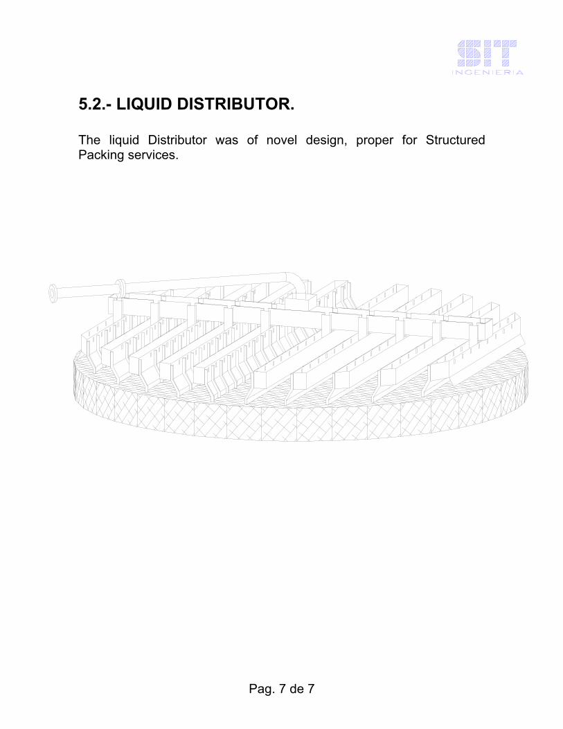
5.2.- LIQUID DISTRIBUTOR. The liquid Distributor was of novel design, proper for Structured Packing services.
Pag. 7 de 7
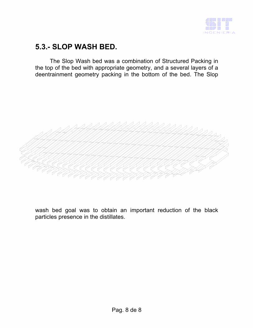
5.3.- SLOP WASH BED. The Slop Wash bed was a combination of Structured Packing in the top of the bed with appropriate geometry, and a several layers of a deentrainment geometry packing in the bottom of the bed. The Slop
wash bed goal was to obtain an important reduction of the black particles presence in the distillates.
Pag. 8 de 8

5.4.- STRUCTURED GRID. The stripping section of the Column was filled with a bed of Structured Grid, which was designed to produce an efficient gas liquid contact, avoiding the solid deposition by cocking. This grid was successfully used in different bottom Vacuum Column services.
Pag. 9 de 9
6.- RESULTS.
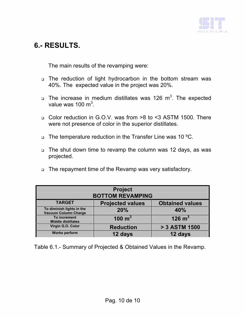
The main results of the revamping were:
The reduction of light hydrocarbon in the bottom stream was 40%. The expected value in the project was 20%.
The increase in medium distillates was 126 m3. The expected
value was 100 m3.
Color reduction in G.O.V. was from >8 to <3 ASTM 1500. There were not presence of color in the superior distillates.
The temperature reduction in the Transfer Line was 10 ºC.
The shut down time to revamp the column was 12 days, as was
projected.
The repayment time of the Revamp was very satisfactory.
Project BOTTOM REVAMPING
TARGET Projected values Obtained values To diminish lights in the Vacuum Column Charge 20% 40%
To increment Middle distillates 100 m3 126 m3
Virgin G.O. Color Reduction > 3 ASTM 1500 Works perform 12 days 12 days
Table 6.1.- Summary of Projected & Obtained Values in the Revamp.
Pag. 10 de 10

Pag. 11 de 11
YIELDS JAN. 1997 Gases & gasoline
1.5%
RC51.9%
HN6.7% LN
7.5%K
9.9%
GOL21.0%
GOV1.4%
YIELDS JAN. 1998 LN
8.9% HN 7.7%
K 7.5%
GOL 27.3% GOV
0.1%
RC 47.1%
Gases & gasoline 1.5%
YIELDS JAN. 1999
HN 8.3%
K 7.3%
GOL 29.4% GOV
0.8%
RC 42.9%
Gases & gasoline 1.5%
LN 8.1%
Graph 6.1.- Compared values of the Products Yield. Previous Revamp, January 1997 and January 1998, and after Revamp, January 1999.

(The seasonal influences on the yields are avoided selecting the same month in order to compare)
Pag. 12 de 12

TOTAL YIELD – CRUDE DENSITY
30.0
35.0
40.0
45.0
50.0
55.0
60.0
%Yield
0.8400
0.8600
0.8800
0.9000
0.9200
0.9400 0.9600
0.9800
1.0000
Density
Yield (%) ´97 Yield (%) ´98 Yield (%) ´99 Crude Dens. (ton/m3) ´97 Crude Dens. (ton/m3) ´98 Crude Dens. (ton/m3) ´99
January
Graph 6.2.- Total Yield Distillates and Crude Density in the different cases.
TOTAL YIELD - TRANSFER LINE TEMPERATURE
20.0 25.0
30.0
35.0
40.0
45.0
50.0
55.0
60.0
4/1 AM 4/1 PM 5/1 AM 5/1 PM 6/1 AM 6/1 PM 7/1 AM 7/1 PM 8/1 AM 8/1 PM
% yield
350
360
370
380
390
400
°C
Yield (%) ´97 Yield (%) ´98 Yield (%) ´99 Transfer Line Temp. (°C) ´97 Transfer Line Temp.(°C) ´98 Transfer Line Temp. (°C) ´99
Graph 6.3.- Total Yield Distillates and Transfer Line Temperature in the different cases.
Pag. 13 de 13

Reduced Crude
Distillation curves, ASTM D86 Without steam injection
at column bottom With steam injection
at column bottom 1st. drop 155 °C 190 °C
5% 289 °C 332 °C 10% 326 °C 360 °C 20% 345 °C 30% 350 °C 35% 360 °C
Table 6.2.- Reduced Crude Curves, according to stripping steam injection (previous and after Revamp).
∆ (previous vs. actual)
Transfer line Temperature (∆ °C) -10 Light Naphtha (∆ m3) -30 Heavy Naphtha (∆ m3) +36 Kerosene (∆ m3) -16 GOL (∆ m3) +142 GOV (∆ m3) +38 Reduced Crude (∆ m3) -170 Yield K+GOL (∆ m3) +126 Yield LN+HN+K+GOL+GOV (∆m3) +170
Table 6.2.- Comparative values, Previous Revamp operation vs. Actual operation (after Revamp).
Pag. 14 de 14
7.- CONCLUSIONS. The Topping Revamp was satisfactory in the different aspects. The Topping operation since the Plant started up was absent of problems. 8.- REFERENCES. 8.1.- Spekuljak, Zvonko & Monella, H., "Reingeniería de Columnas de Vacío con Rellenos Estructurados", Congreso COEXPO ARPEL '96, 5to. Latinoamericano de Hidrocarburos, Rio de Janeiro, oct. 1996. 8.2.- Spekuljak, Zvonko & Monella, H., "Fluid Distributors for Structured Packing Columns", AIChE 1998 Annual Meeting, Miami, Fl. 8.3.- “A new Concept of Structured Packing Column Auxiliaries”, Chem. Eng. Technol., 17, 1994, p. 61. 8.4.- “The Effects of some Constructive Details on Structured Packing Columns Performance”, Latin American Appl. Research, 26., 1996, p. 107.
Pag. 15 de 15