
REV08 TOMAHAWK 1025 & 1538 - Lincoln Electric
14
IM2014 03/2021 REV08 TOMAHAWK 1025 & 1538 OPERATOR’S MANUAL ENGLISH Lincoln Electric Bester Sp. z o.o. ul. Jana III Sobieskiego 19A, 58-260 Bielawa, Poland www.lincolnelectric.eu
Transcript of REV08 TOMAHAWK 1025 & 1538 - Lincoln Electric
IM2014 03/2021 REV08
TOMAHAWK 1025 & 1538
OPERATOR’S MANUAL
ENGLISH
Lincoln Electric Bester Sp. z o.o.
ul. Jana III Sobieskiego 19A, 58-260 Bielawa, Poland www.lincolnelectric.eu
English English I
12/05
THANKS! For having choosen the QUALITY of the Lincoln Electric products. Please Examine Package and Equipment for Damage. Claims for material damaged in shipment must be notified
immediately to the dealer. For future reference record in the table below your equipment identification information. Model Name, Code &
Serial Number can be found on the machine rating plate.
Model Name:
………………...…………………………….………………………………………………………………………………………….. Code & Serial number:
………………….……………………………………………….. …………………………………………………….……………..
Date & Where Purchased:
…………………………………………………………………... ……………………….…………………………………………..
ENGLISH INDEX Technical Specifications ...................................................................................................................................................... 1 ECO design information ...................................................................................................................................................... 2 Electromagnetic Compatibility (EMC) .................................................................................................................................. 4 Safety .................................................................................................................................................................................. 5 Installation and Operator Instructions .................................................................................................................................. 7 WEEE ............................................................................................................................................................................... 12 Spare Parts ....................................................................................................................................................................... 12 REACh .............................................................................................................................................................................. 12 Authorized Service Shops Location .................................................................................................................................. 12 Electrical Schematic .......................................................................................................................................................... 12

English 1 English
Technical Specifications
NAME INDEX
TOMAHAWK 1025 K12048-1
TOMAHAWK 1538 K12039-1
INPUT
Input Voltage Input Power at Rated Output EMC Class Frequency
400V ±15% Three Phase
TH1025 4.3kW @ 100% Duty Cycle
A 50/60Hz 7.1kW @ 40% Duty Cycle
TH1538 7.1kW @ 100% Duty Cycle
13.7kW @ 40% Duty Cycle
RATED OUTPUT AT 40°C
Duty Cycle (Based on a 10 min. period) Output Current Output Voltage
TH1025
100% 40A 96VDC
60% 50A 100VDC
40% 60A 104VDC
TH1538
100% 60A 104VDC
60% 85A 114VDC
40% 100A 120VDC
OUTPUT RANGE
Cutting Current Range Maximum Open Circuit Voltage Pilot Arc Current
TH1025 20 - 60A 320VDC 20A
TH1538 20 - 100A 320VDC 20A
COMPRESSED AIR or GAS
Required Flow Rate Required Inlet Pressure
TH1025 130 ±20% l/min @ 5.5bar 6.0bar ÷ 7.5bar
TH1538 280 ±20% l/min @ 5.5bar
RECOMMENDED INPUT CABLE AND FUSE SIZES
Fuse (delayed) or Circuit Breaker (“D”
characteristic) Size Input Power Cable
TH1025 20A 4 x 2.5mm2
TH1538 32A 4 x 4mm2
PHYSICAL DIMENSIONS
Height Width Length Weight
TH1025 389mm 247mm 510mm 22kg
TH1538 455mm 301mm 640mm 34kg
Operating Temperature Storage Temperature
-10°C to +40°C -25°C to +55°C
English 2 English
ECO design information The equipment has been designed in order to be compliant with the Directive 2009/125/EC and the Regulation 2019/1784/EU. Efficiency and idle power consumption:
Index Name Efficiency when max power
consumption / Idle power consumption Equivalent model
K12048-1 TOMAHAWK 1025 87,6% / 21W No equivalent model
K12039-1 TOMAHAWK 1538 86,8% / 21W No equivalent model
Idle state occurs under the condition specified in below table
IDLE STATE
Condition Presence
MIG mode
TIG mode
STICK mode
After 30 minutes of non-working
Fan off X
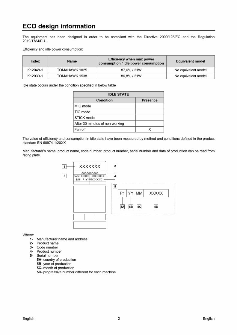
The value of efficiency and consumption in idle state have been measured by method and conditions defined in the product standard EN 60974-1:20XX Manufacturer’s name, product name, code number, product number, serial number and date of production can be read from rating plate.
XXXXXXXXXXCode: XXXXX XXXXXX-X
S/N: P1YYMMXXXXX
1 2
3 4
5
P1 YY MM XXXXX
5A5A 5B 5D5C
XXXXXXX
Where:
1- Manufacturer name and address 2- Product name 3- Code number 4- Product number 5- Serial number
5A- country of production 5B- year of production 5C- month of production 5D- progressive number different for each machine
English 3 English
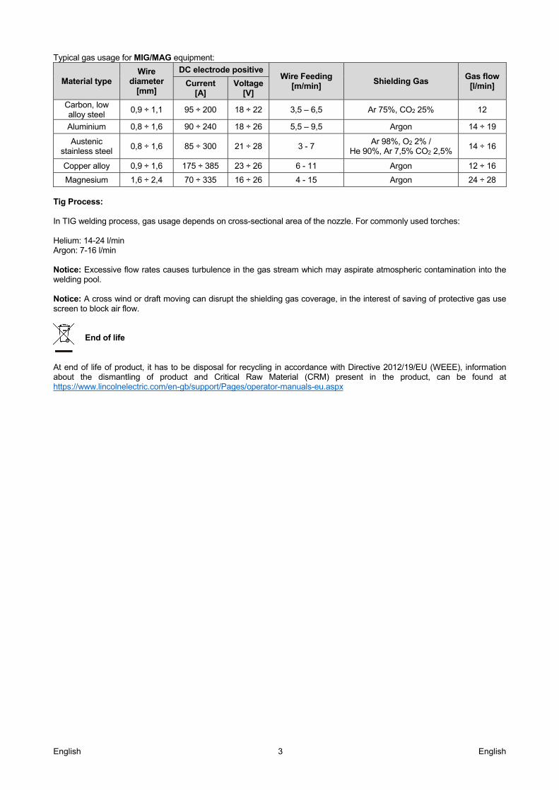
Typical gas usage for MIG/MAG equipment:
Material type Wire
diameter [mm]
DC electrode positive Wire Feeding
[m/min] Shielding Gas
Gas flow [l/min] Current
[A] Voltage
[V] Carbon, low alloy steel
0,9 ÷ 1,1 95 ÷ 200 18 ÷ 22 3,5 – 6,5 Ar 75%, CO2 25% 12
Aluminium 0,8 ÷ 1,6 90 ÷ 240 18 ÷ 26 5,5 – 9,5 Argon 14 ÷ 19
Austenic stainless steel
0,8 ÷ 1,6 85 ÷ 300 21 ÷ 28 3 - 7 Ar 98%, O2 2% /
He 90%, Ar 7,5% CO2 2,5% 14 ÷ 16
Copper alloy 0,9 ÷ 1,6 175 ÷ 385 23 ÷ 26 6 - 11 Argon 12 ÷ 16
Magnesium 1,6 ÷ 2,4 70 ÷ 335 16 ÷ 26 4 - 15 Argon 24 ÷ 28
Tig Process: In TIG welding process, gas usage depends on cross-sectional area of the nozzle. For commonly used torches: Helium: 14-24 l/min Argon: 7-16 l/min Notice: Excessive flow rates causes turbulence in the gas stream which may aspirate atmospheric contamination into the welding pool. Notice: A cross wind or draft moving can disrupt the shielding gas coverage, in the interest of saving of protective gas use screen to block air flow.
End of life
At end of life of product, it has to be disposal for recycling in accordance with Directive 2012/19/EU (WEEE), information about the dismantling of product and Critical Raw Material (CRM) present in the product, can be found at https://www.lincolnelectric.com/en-gb/support/Pages/operator-manuals-eu.aspx
English 4 English
Electromagnetic Compatibility (EMC) 01/11
This machine has been designed in accordance with all relevant directives and standards. However, it may still generate electromagnetic disturbances that can affect other systems like telecommunications (telephone, radio, and television) or other safety systems. These disturbances can cause safety problems in the affected systems. Read and understand this section to eliminate or reduce the amount of electromagnetic disturbance generated by this machine.
This machine has been designed to operate in an industrial area. The operator must install and operate this equipment as described in this manual. If any electromagnetic disturbances are detected the operator must put in place corrective actions to eliminate these disturbances with, if necessary, assistance from Lincoln Electric. This equipment does not comply with IEC 61000-3-12. If it is connected to a public low-voltage
system, it is responsibility of the installer or user of the equipment to ensure, by consultation with the distribution network operator if necessary, that the equipment may be connected. Before installing the machine, the operator must check the work area for any devices that may malfunction because of electromagnetic disturbances. Consider the following. Input and output cables, control cables, and telephone cables that are in or adjacent to the work area and the
machine. Radio and/or television transmitters and receivers. Computers or computer controlled equipment. Safety and control equipment for industrial processes. Equipment for calibration and measurement. Personal medical devices like pacemakers and hearing aids. Check the electromagnetic immunity for equipment operating in or near the work area. The operator must be sure
that all equipment in the area is compatible. This may require additional protection measures. The dimensions of the work area to consider will depend on the construction of the area and other activities that are
taking place. Consider the following guidelines to reduce electromagnetic emissions from the machine. Connect the machine to the input supply according to this manual. If disturbances occur if may be necessary to take
additional precautions such as filtering the input supply. The output cables should be kept as short as possible and should be positioned together. If possible connect the
work piece to ground in order to reduce the electromagnetic emissions. The operator must check that connecting the work piece to ground does not cause problems or unsafe operating conditions for personnel and equipment.
Shielding of cables in the work area can reduce electromagnetic emissions. This may be necessary for special applications.
WARNING The Class A equipment is not intended for use in residential locations where the electrical power is provided by the public low-voltage supply system. There can be potential difficulties in ensuring electromagnetic compatibility in those locations, due to conducted as well as radio-frequency disturbances.

English 5 English
Safety 01/11
WARNING This equipment must be used by qualified personnel. Be sure that all installation, operation, maintenance and repair procedures are performed only by qualified person. Read and understand this manual before operating this equipment. Failure to follow the instructions in this manual could cause serious personal injury, loss of life, or damage to this equipment. Read and understand the following explanations of the warning symbols. Lincoln Electric is not responsible for damages caused by improper installation, improper care or abnormal operation.
WARNING: This symbol indicates that instructions must be followed to avoid serious personal injury, loss of life, or damage to this equipment. Protect yourself and others from possible serious injury or death.
READ AND UNDERSTAND INSTRUCTIONS: Read and understand this manual before operating this equipment. Plasma cutting or gouging can be hazardous. Failure to follow the instructions in this manual could cause serious personal injury, loss of life, or damage to this equipment.
ELECTRICALLY POWERED EQUIPMENT: Turn off input power using the disconnect switch at the fuse box before working on this equipment. Ground this equipment in accordance with local electrical regulations.
ELECTRIC AND MAGNETIC FIELDS MAY BE DANGEROUS: Electric current flowing through any conductor creates electric and magnetic fields (EMF). EMF fields may interfere with some pacemakers, and welders having a pacemaker shall consult their physician before operating this equipment.
CE COMPLIANCE: This equipment complies with the European Community Directives.
ARTIFICIAL OPTICAL RADIATION: According with the requirements in 2006/25/EC Directive and EN 12198 Standard, the equipment is a category 2. It makes mandatory the adoption of Personal Protective Equipments (PPE) having filter with a protection degree up to a maximum of 15, as required by EN169 Standard.
WORK MATERIALS CAN BURN: Cutting generates a large amount of heat. Hot surfaces and materials in work area can cause serious burns. Use gloves and pliers when touching or moving materials in the work area.
EQUIPMENT WEIGHT OVER 30kg: Move this equipment with care and with the help of another person. Lifting may be dangerous for your physical health.
CYLINDER MAY EXPLODE IF DAMAGED: Use only compressed gas cylinders containing the correct shielding gas for the process used and properly operating regulators designed for the gas and pressure used. Always keep cylinders in an upright position securely chained to a fixed support. Do not move or transport gas cylinders with the protection cap removed. Do not allow the torch, work clamp or any other electrically live part to touch a gas cylinder. Gas cylinders must be located away from areas where they may be subjected to physical damage or the cutting process including sparks and heat sources.
Cutting sparks can cause explosion or fire. Keep flammables away from cutting. Do not cut near flammables. Have a fire extinguisher nearby, and have a watch person ready to use it. Do not cut on drums or any closed container.
English 6 English
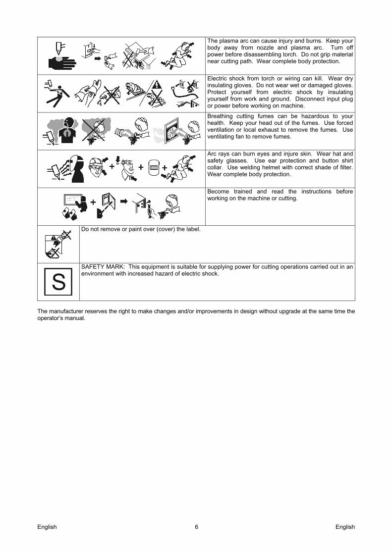
The plasma arc can cause injury and burns. Keep your body away from nozzle and plasma arc. Turn off power before disassembling torch. Do not grip material near cutting path. Wear complete body protection.
Electric shock from torch or wiring can kill. Wear dry insulating gloves. Do not wear wet or damaged gloves. Protect yourself from electric shock by insulating yourself from work and ground. Disconnect input plug or power before working on machine.
Breathing cutting fumes can be hazardous to your health. Keep your head out of the fumes. Use forced ventilation or local exhaust to remove the fumes. Use ventilating fan to remove fumes.
Arc rays can burn eyes and injure skin. Wear hat and safety glasses. Use ear protection and button shirt collar. Use welding helmet with correct shade of filter. Wear complete body protection.
Become trained and read the instructions before working on the machine or cutting.
Do not remove or paint over (cover) the label.
SAFETY MARK: This equipment is suitable for supplying power for cutting operations carried out in an environment with increased hazard of electric shock.
The manufacturer reserves the right to make changes and/or improvements in design without upgrade at the same time the operator’s manual.
English 7 English
Installation and Operator Instructions Read this entire section before installation or operation of the machine.
Location and Environment This machine can operate in harsh environments. However, it is important that simple preventative measures are followed to assure long life and reliable operation: Do not place or operate this machine on a surface
with an incline greater than 15° from horizontal. Do not use this machine for pipe thawing. This machine must be located where there is free
circulation of clean air without restrictions for air movement to and from the air vents. Do not cover the machine with paper, cloth or rags when switched on.
Dirt and dust that can be drawn into the machine should be kept to a minimum.
This machine has a protection rating of IP23. Keep it dry when possible and do not place it on wet ground or in puddles.
Locate the machine away from radio controlled machinery. Normal operation may adversely affect the operation of nearby radio controlled machinery, which may result in injury or equipment damage. Read the section on electromagnetic compatibility in this manual.
Do not operate in areas with an ambient temperature greater than 40°C.
Duty Cycle The duty cycle of a plasma machine is the percentage of time in a 10 minute cycle at which the operator can operate the machine at rated cutting current. Example: 60% duty cycle means that is possible cut for 6 minutes, then the machine stops for 4 minutes. Refer to the Technical Specification section for more information about the machine rated duty cycles.
Input Supply Connection Check the input voltage, phase, and frequency supplied to this machine before turning it on. The allowable input voltage is indicated in the technical specification section of this manual and on the rating plate of the machine. Be sure that the machine is grounded. Make sure the amount of power available from the input connection is adequate for normal operation of the machine. The fuse rating and cable sizes are both indicated in the technical specification section of this manual. This machine is designed to operate on engine driven generators as long as the 400Vac auxiliary can supply adequate power as indicated in the technical specification section of this manual. The auxiliary supply of the generator must also meet the following conditions. The AC waveform peak voltage is below 700V. The AC waveform frequency is between 50 and 60
Hz. The RMS voltage of the AC waveform is always
equal to 400Vac ±15%.
It is important to check these conditions because many engine driven generators produce high voltage spikes. Operation of this machine on engine driven generators not conforming to these conditions is not recommended and may damage the machine.
Output Connections
WARNING Use ONLY the torch supplied with this machine. For a replacement refer to the Maintenance section of this manual.
WARNING TORCH PROTECTION: The torch delivered with the power source is equipped with a safety device that prevents the operator from accidental contact with electrically live parts.
WARNING Always turn OFF the machine when working on the torch.
WARNING Do not remove the work clamp during cutting, plasma cutting generates high voltages that can kill.
WARNING Open Circuit Voltage U0 > 100VDC. For more information refer to the Technical Specification section.
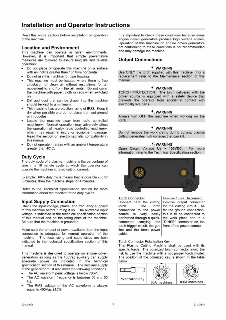
Torch Connector: Connect here the cutting torch. The torch connection to the power source is very easily performed through a quick-connector carrying the torch trigger circuit, the gas line and the torch power cable.
Positive Quick Disconnect: Positive output connector for the cutting circuit. As far the ground connection, this is to be connected to the work piece and to a "DINSE" connector on the front of the power source.
Torch Connector Polarization Key: This Plasma Cutting Machine shall be used with its specific torch. The polarized torch connector avoid the risk to use the machine with a not proper torch model. The position of the polarized key is shown in the table below.
Polarization Key 60A machines
100A machines
English 8 English
Controls and Operational Features Machine Auto-Test: When the machine is turned ON, an auto-test is executed; during this test all of the LEDs of the Commands Front Panel lights up. If one or some LED remains OFF, contact the nearest technical service center or Lincoln Electric and report the LED Status found on the machine Front Panel. Front Panel Controls
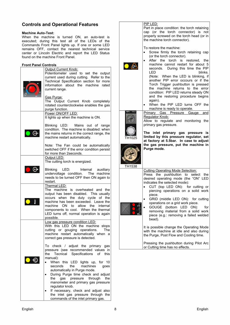
Output Current Knob: Potentiometer used to set the output current used during cutting. Refer to the Technical Specification section for more information about the machine rated current range. Gas Purge: The Output Current Knob completely rotated counterclockwise enables the gas purge function.
Power ON/OFF LED: It lights up when the machine is ON. Blinking LED: Mains out of range condition. The machine is disabled: when the mains returns in the correct range, the machine restart automatically. Note: The Fan could be automatically switched OFF if the error condition persist for more than 2seconds.
Output LED: The cutting torch is energized. Blinking LED: Internal auxiliary undervoltage condition. The machine needs to be turned OFF then ON again to restart.
Thermal LED: The machine is overheated and the output has been disabled. This usually occurs when the duty cycle of the machine has been exceeded. Leave the machine ON to allow the internal components to cool. When the thermal LED turns off, normal operation is again possible.
Low gas pressure condition LED: With this LED ON the machine stops cutting or gouging operations. The machine restart automatically when a correct gas pressure is detected. To check / adjust the primary gas pressure (see recommended values in the Tecnical Specifications of this manual): When this LED lights up, for 10
seconds the machines goes automatically in Purge mode.
During Purge time check and adjust the gas pressure through the manometer and primary gas pressure regulator knob.
If necessary, check and adjust also the inlet gas pressure through the commands of the inlet primary gas.
PIP LED: Part in place condition: the torch retaining cap (or the torch connector) is not properly screwed on the torch head (or in the machine torch connector). To restore the machine: Screw firmly the torch retaining cap
(or the torch connector). After the torch is restored, the
machine cannot restart for about 5 seconds. During this time the PIP LED blinks. (Note: When the LED is blinking, if another PIP error occours or if the Torch Trigger pushbutton is pressed the machine returns to the error condition: PIP LED returns steady ON and the restoring procedure begins again).
When the PIP LED turns OFF the machine is ready to operate.
TH1025
TH1538
Primary Gas Pressure Gauge and Regulator Knob: Allow to regulate and monitoring the primary gas pressure. The inlet primary gas pressure is limited by this pressure regulator, set at factory at 5.5bar. In case to adjust the gas pressure, put the machine in Purge mode.
Cutting Operating Mode Selection: Press the pushbutton to select the desired operating mode (the “ON” LED indicates the selected mode): CUT (top LED ON): for cutting or
piercing operations on a solid work piece.
GRID (middle LED ON): for cutting operations on a grid work piece.
GOUGE (bottom LED ON): for removing material from a solid work piece (e.g.: removing a failed welded bead).
It is possible change the Operating Mode with the machine at idle and also during the Purge, Post Flow and Cooling time. Pressing the pushbutton during Pilot Arc or Cutting time has no effects.
English 9 English
Error condition list If occurs, try to turn Off the machine, wait for a few seconds, then turn ON again. If the error remains, a maintenance is required. Please contact the nearest technical service center or Lincoln Electric and report the LED Status found on the machine Front Panel.
Head Torch
On Blink Blink This occurs if after 4seconds the Pilot Arc isn’t transfered to the workpiece. The machine stops the pilot arc to avoid overheating on the Torch Head. To restore the machine: Release the Torch Trigger
pushbutton. The blinking LEDs are now permanently ON
Press again the release the Torch Trigger pushbutton.
No pilot arc estabilished
On On On The Torch Trigger pushbutton is pressed. During this period the machine try to start the pilot arc for 4 times. If the pilot arc doesn’t start the machine automatically goes in a safe condition that allow to check as necessary. To restore the machine: Turn OFF the Power switch. Check the correct placement of the
Torch Head consumables and parts. Check the Torch electrical
connections. Turn ON again the machine.
Trigger Pushed
On On On On This occurs if the machine is switched ON (or if it restart after cooling time) with the Torch Trigger pushbutton hold. This status avoids unsafe operating conditions: manual cutting or gouging processes must be started ONLY under the direct control of the operator. To restore the machine: Release the Torch Trigger
pushbutton. Press again the Torch Trigger
pushbutton. If this error condition persist check for eventual malfunctions of the the Torch Trigger pushbutton.
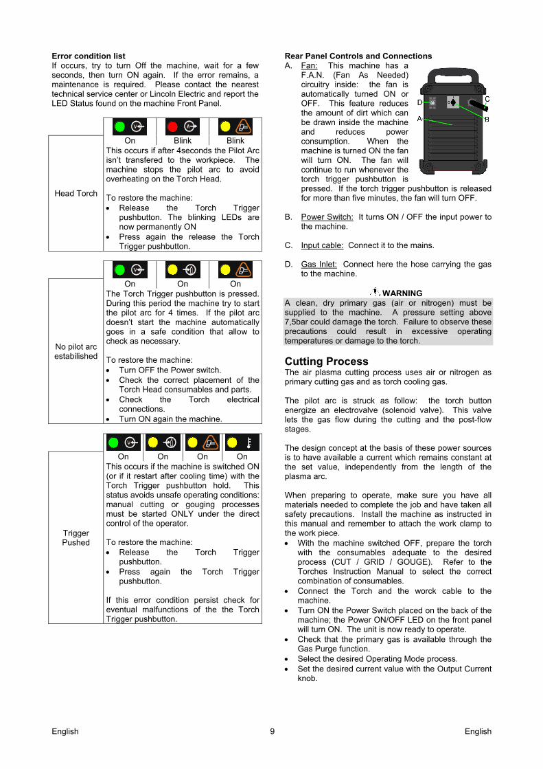
Rear Panel Controls and Connections A. Fan: This machine has a
F.A.N. (Fan As Needed) circuitry inside: the fan is automatically turned ON or OFF. This feature reduces the amount of dirt which can be drawn inside the machine and reduces power consumption. When the machine is turned ON the fan will turn ON. The fan will continue to run whenever the torch trigger pushbutton is pressed. If the torch trigger pushbutton is released for more than five minutes, the fan will turn OFF.
B. Power Switch: It turns ON / OFF the input power to
the machine. C. Input cable: Connect it to the mains. D. Gas Inlet: Connect here the hose carrying the gas
to the machine.
WARNING A clean, dry primary gas (air or nitrogen) must be supplied to the machine. A pressure setting above 7,5bar could damage the torch. Failure to observe these precautions could result in excessive operating temperatures or damage to the torch.
Cutting Process The air plasma cutting process uses air or nitrogen as primary cutting gas and as torch cooling gas. The pilot arc is struck as follow: the torch button energize an electrovalve (solenoid valve). This valve lets the gas flow during the cutting and the post-flow stages. The design concept at the basis of these power sources is to have available a current which remains constant at the set value, independently from the length of the plasma arc. When preparing to operate, make sure you have all materials needed to complete the job and have taken all safety precautions. Install the machine as instructed in this manual and remember to attach the work clamp to the work piece. With the machine switched OFF, prepare the torch
with the consumables adequate to the desired process (CUT / GRID / GOUGE). Refer to the Torches Instruction Manual to select the correct combination of consumables.
Connect the Torch and the worck cable to the machine.
Turn ON the Power Switch placed on the back of the machine; the Power ON/OFF LED on the front panel will turn ON. The unit is now ready to operate.
Check that the primary gas is available through the Gas Purge function.
Select the desired Operating Mode process. Set the desired current value with the Output Current
knob.

English 10 English
To start the selected process just press the torch button, making sure you are not aiming the torch gas blow towards people or foreign objects. During the process it is possible to hold the torch away from the work piece for an extended period of time. Once the process is terminated releasing off the torch button will cause the plasma arc to be turned off; the gas flow will continue to allow the cooling down of the torch. The Post Flow time is proportional to the selected cutting current and it is divided into 4 time ranges:
Selected Cutting Current Post Flow Time
Less than 30A 15seconds
Between 30A and 40A 20seconds
Between 40A and 50A 25seconds
Greater than 50A 30seconds
Maintenance
WARNING For any maintenance or repair operations it is recommended to contact the nearest technical service center or Lincoln Electric. Maintenance or repairs performed by unauthorized service centers or personnel will null and void the manufacturers warranty. The frequency of the maintenance operations may vary in accordance with the working environment. Any noticeable damage should be reported immediately. Check cables and connections integrity. Replace, if
necessary. Regularly clean the torch head, check its
consumables and if necessary replace them.
WARNING Refer to the torch instructions before changing or servicing the torch. Keep clean the machine. Use a soft dry cloth to
clean the enclosing case, especially the airflow inlet / outlet louvers.
WARNING
Do not open this machine and do not introduce anything into its openings. Power supply must be disconnected from the machine before maintenance and service. After each repair, perform proper tests to check safety requirements.
Customer Assistance Policy The business of The Lincoln Electric Company is manufacturing and selling high quality welding equipment, consumables, and cutting equipment. Our challenge is to meet the needs of our customers and to exceed their expectations. On occasion, purchasers may ask Lincoln Electric for advice or information about their use of our products. We respond to our customers based on the best information in our possession at that time. Lincoln Electric is not in a position to warrant or guarantee such advice, and assumes no liability, with respect to such information or advice. We expressly disclaim any warranty of any kind, including any warranty of fitness for any customer’s particular purpose, with respect to such information or advice. As a matter of practical consideration, we also cannot assume any responsibility for updating or correcting any such information or advice once it has been given, nor does the provision of information or advice create, expand or alter any warranty with respect to the sale of our products Lincoln Electric is a responsive manufacturer, but the selection and use of specific products sold by Lincoln Electric is solely within the control of, and remains the sole responsibility of the customer. Many variables beyond the control of Lincoln Electric affect the results obtained in applying these types of fabrication methods and service requirements. Subject to Change – This information is accurate to the best of our knowledge at the time of printing. Please refer to www.lincolnelectric.com for any updated information.
English 11 English
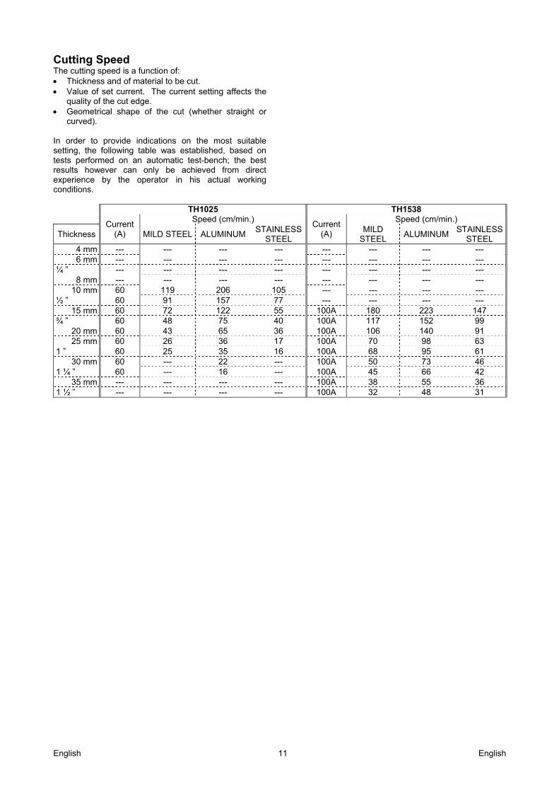
Cutting Speed The cutting speed is a function of: Thickness and of material to be cut. Value of set current. The current setting affects the
quality of the cut edge. Geometrical shape of the cut (whether straight or
curved). In order to provide indications on the most suitable setting, the following table was established, based on tests performed on an automatic test-bench; the best results however can only be achieved from direct experience by the operator in his actual working conditions.
TH1025 TH1538
Current (A)
Speed (cm/min.) Current
(A)
Speed (cm/min.)
Thickness MILD STEEL ALUMINUM STAINLESS
STEEL MILD
STEEL ALUMINUM
STAINLESS STEEL
4 mm --- --- --- --- --- --- --- --- 6 mm --- --- --- --- --- --- --- ---
¼ ” --- --- --- --- --- --- --- --- 8 mm --- --- --- --- --- --- --- ---
10 mm 60 119 206 105 --- --- --- --- ½ ” 60 91 157 77 --- --- --- ---
15 mm 60 72 122 55 100A 180 223 147 ¾ ” 60 48 75 40 100A 117 152 99
20 mm 60 43 65 36 100A 106 140 91 25 mm 60 26 36 17 100A 70 98 63
1 ” 60 25 35 16 100A 68 95 61 30 mm 60 --- 22 --- 100A 50 73 46
1 ¼ ” 60 --- 16 --- 100A 45 66 42 35 mm --- --- --- --- 100A 38 55 36
1 ½ ” --- --- --- --- 100A 32 48 31
English 12 English
WEEE 07/06
Do not dispose of electrical equipment together with normal waste! In observance of European Directive 2012/19/EC on Waste Electrical and Electronic Equipment (WEEE) and its implementation in accordance with national law, electrical equipment that has reached the end of its life must be collected separately and returned to an environmentally compatible recycling facility. As the owner of the equipment, you should get information on approved collection systems from our local representative. By applying this European Directive you will protect the environment and human health!
Spare Parts 12/05
Part List reading instructions Do not use this part list for a machine if its code number is not listed. Contact the Lincoln Electric Service
Department for any code number not listed. Use the illustration of assembly page and the table below to determine where the part is located for your particular
code machine. Use only the parts marked "X" in the column under the heading number called for in the assembly page (# indicate
a change in this printing).
First, read the Part List reading instructions above, then refer to the "Spare Part" manual supplied with the machine, that contains a picture-descriptive part number cross-reference.
REACh 11/19
Communication in accordance with Article 33.1 of Regulation (EC) No 1907/2006 – REACh. Some parts inside this product contain: Bisphenol A, BPA, EC 201-245-8, CAS 80-05-7 Cadmium, EC 231-152-8, CAS 7440-43-9 Lead, EC 231-100-4, CAS 7439-92-1 Phenol, 4-nonyl-, branched, EC 284-325-5, CAS 84852-15-3 in more than 0,1% w/w in homogeneous material. These substances are included in the “Candidate List of Substances of Very High Concern for Authorisation” of REACh. Your particular product may contain one or more of the listed substances. Instructions for safe use: use according to Manufacturer instructions, wash hands after use; keep out of reach of children, do not put in mouth, dispose in accordance with local regulations.
Authorized Service Shops Location 09/16
The purchaser must contact a Lincoln Authorized Service Facility (LASF) about any defect claimed under Lincoln's warranty period.
Contact your local Lincoln Sales Representative for assistance in locating a LASF or go to www.lincolnelectric.com/en-gb/Support/Locator.
Electrical Schematic Refer to the "Spare Part" manual supplied with the machine.


