rev. BX-A / BX-B - Vartutechnika.ltvartutechnika.lt/assets/PDF_instrukcijos/nustumiami/C2-BX.pdf ·...
45
Documentazione Tecnica S17 rev. 2.1 07/2002 © CAME CANCELLI AUTOMATICI CANCELLI AUTOMATICI BX-A / BX-B ITALIANO / ENGLISH / ESPAÑOL 119BS17-1 SERIE BX | BX SERIES | SERIE BX 3 x 1.5 / 230V 2 x 1 - TX 2 x 1 2 x 1.5 RG58 6 5 9 3 1 2 4 9 10 10 4 x 1 - RX 11 3 x 1.5 / 230V 2 x 1 - TX 3 x 1 2 x 1.5 RG58 4 7 6 5 9 3 1 2 4 10 2 x 1 - TX 4 x 1 - RX 11 4 x 1 - RX 8 12 Automazioni per cancelli scorrevoli Automation systems for sliding gates Automatización para puertas correderas 1 - BX unit 2 - Control board 3 - Radio receiver 4 - Limit-switch tabs 5 - Rack 6 - Key-operated selector switch 7 - Flashing light indicating door movement 8 - Antenna 9 - Safety photocells 10 - Photocell column 11 - Closure stop 12 - Radio transmitter Standard installation 1 - Gruppo BX 2 - Scheda comando 3 - Ricevitore radio 4 - Alette finecorsa 5 - Cremagliera 6 - Selettore a chiave 7 - Lampeggiatore di movimento 8 - Antenna di ricezione 9 - Fotocellule di sicurezza 10 - Colonnina per fotocellula 11 - Fermo anta 12 - trasmettitore radio Impianto tipo Instalación tipo 1 - Conjunto BX 2 - Tarjeta de mando 3 - Radiorreceptor 4 - Aletas de tope 5 - Cremallera 6 - Selector mediante llave 7 - Lámpara intermitente de movimiento 8 - Antena receptora 9 - Fotocélulas de seguridad 10 - Columna para fotocélula 11 - Tope puerta 12 - transmisor
Transcript of rev. BX-A / BX-B - Vartutechnika.ltvartutechnika.lt/assets/PDF_instrukcijos/nustumiami/C2-BX.pdf ·...
DocumentazioneTecnica
S17rev. 2.107/2002© CAME
CANCELLIAUTOMATICI
CANCELLI AUTOMATICI
BX-A / BX-B
ITA
LIA
NO
/EN
GL
ISH
/ES
PA
ÑO
L
119BS17-1
SERIE BX | BX SERIES | SERIE BX
3 x 1.5 / 230V
2 x 1 - TX
2 x 1
2 x 1.5
RG58
6
5
9
31 2
4
9
10
10
4 x 1 - RX
11
3 x 1.5 / 230V
2 x 1 - TX
3 x 1
2 x 1.5
RG58
4
76
5
9
31 2
410
2 x 1 - TX
4 x 1 - RX
11
4 x 1 - RX
8
12
Automazioni per cancelli scorrevoliAutomation systems for sliding gates
Automatización para puertas correderas
1 - BX unit2 - Control board3 - Radio receiver4 - Limit-switch tabs5 - Rack6 - Key-operated selector switch7 - Flashing light indicating door movement8 - Antenna9 - Safety photocells10 - Photocell column11 - Closure stop12 - Radio transmitter
Standard installation
1 - Gruppo BX2 - Scheda comando3 - Ricevitore radio4 - Alette finecorsa5 - Cremagliera6 - Selettore a chiave7 - Lampeggiatore di movimento8 - Antenna di ricezione9 - Fotocellule di sicurezza10 - Colonnina per fotocellula11 - Fermo anta12 - trasmettitore radio
Impianto tipo Instalación tipo
1 - Conjunto BX2 - Tarjeta de mando3 - Radiorreceptor4 - Aletas de tope5 - Cremallera6 - Selector mediante llave7 - Lámpara intermitente de movimiento8 - Antena receptora9 - Fotocélulas de seguridad10 - Columna para fotocélula11 - Tope puerta12 - transmisor
-2-
ITA
LIA
NO
•
EN
GLI
SH
•
ES
PAÑ
OL CARATTERISTICHE GENERALI - GENERAL SPECIFICATIONS - CARACTERÍSTICAS GENERALES
- Progettato e costruito interamentedalla CAME Cancelli automatici S.p.A.
- Grado di protezione IP54.
- Garantito 24 mesi salvo manomissio-ni.
- Designed and constructed entirely byCAME Cancelli automatici S.p.A.
- IP 54 protection rating.
-24 mounth guarantee; guarantee void ifunit is tampered with.
- Diseñado y construido totalmente porCAME Cancelli Automatici S.p.A.
- Grado de protección IP54.
-Garantia de 24 meses salvo manipula-ciones.
CARATTERISTICHE TECNICHE - TECHNICAL CHARACTERISTICS - CARACTERISTICAS TECNICAS
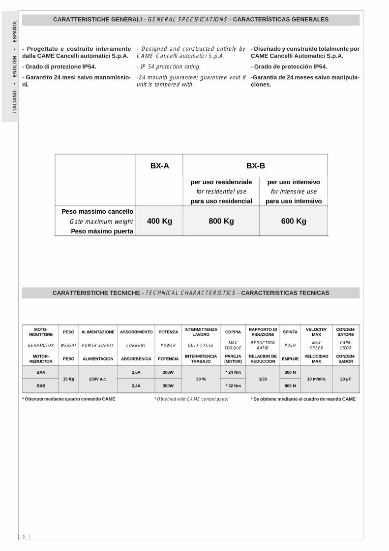
* Ottenuta mediante quadro comando CAME * Se obtiene mediante el cuadro de mando CAME* Obtained with CAME control panel
MOTO-RIDUTTORE
PESO ALIMENTAZIONE ASSORBIMENTO POTENZAINTERMITTENZA
LAVOROCOPPIA
RAPPORTO DIRIDUZIONE
SPINTAVELOCITA'
MAXCONDEN-SATORE
GEARMOTOR WEIGHT POWER SUPPLY CURRENT POWER DUTY CYCLEMAX
TORQUEREDUCTION
RATIOPUSH
MAXSPEED
CAPA-CITOR
MOTOR-REDUCTOR
PESO ALIMENTACION ABSORBENCIA POTENCIAINTERMITENCIA
TRABAJOPAREJA(MOTOR)
RELACION DEREDUCCION
EMPUJEVELOCIDAD
MAXCONDEN-SADOR
BXA
15 Kg 230V a.c.
2,6A 200W
30 %
* 24 Nm
1/33
300 N
10 m/min. 20 µF
BXB 2,4A 300W * 32 Nm 800 N
BX-A BX-B
per uso residenziale per uso intensivofor residential use for intensive use
para uso residencial para uso intensivo
Peso massimo cancello
400 Kg 800 Kg 600 KgGate maximum weight
Peso máximo puerta
-3-
ITA
LIA
NO
•
EN
GLI
SH
•
ES
PAÑ
OL
���
���
������
������
���
���
��
��
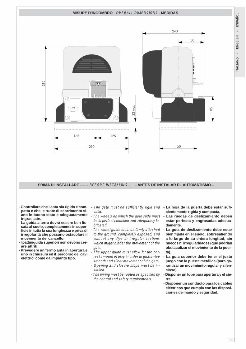
MISURE D'INGOMBRO - OVERALL DIMENSIONS - MEDIDAS
PRIMA DI INSTALLARE ...... - BEFORE INSTALLING ..... - ANTES DE INSTALAR EL AUTOMATISMO...
- Controllare che l'anta sia rigida e com-patta e che le ruote di scorrimento si-ano in buono stato e adeguatamenteingrassate.
- La guida a terra dovrà essere ben fis-sata al suolo, completamente in super-ficie in tutta la sua lunghezza e priva diirregolarità che possano ostacolare ilmovimento del cancello.
- I pattiniguida superiori non devono cre-are attriti.
- Prevedere un fermo anta in apertura euno in chiusura ed il percorso dei cavielettrici come da impianto tipo.
- The gate must be sufficiently rigid andsolid.
- The wheels on which the gate slide mustbe in perfect condition and adequately lu-bricated.
- The wheel guide must be firmly attachedto the ground, completely exposed, andwithout any dips or irregular sectionswhich might hinder the movement of thegate.
- The upper guide must allow for the cor-rect amount of play in order to guaranteesmooth and silent movement of the gate.
- Opening and closure stops must be in-stalled.
- The wiring must be routed as specified bythe control and safety requirements.
- La hoja de la puerta debe estar sufi-cientemente rigida y compacta.
- Las ruedas de deslizamiento debenestar perfecta y engrasadas adecua-damente.
- La guia de deslizamiento debe estarbien fijada en el suelo, sobresaliendoa lo largo de su entera longitud, sinhuecos ni irregularidades (que podrianobstaculizar el movimiento de la puer-ta).
- La guia superior debe tener el justojuego con la puerta metálica (para ga-rantizar un movimiento regular y silen-cioso).
- Disponer un tope para apertura y el cie-rre.
- Disponer un conducto para los cableseléctricos que cumpla con las disposi-ciones de mando y seguridad.
-4-
ITA
LIA
NO
•
EN
GLI
SH
•
ES
PAÑ
OL
75 mm.
105
mm
.
50 m
m.
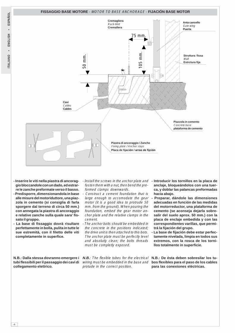
FISSAGGIO BASE MOTORE - MOTOR TO BASE ANCHORAGE - FIJACIÓN BASE MOTOR
- Inserire le viti nella piastra di ancorag-gio bloccandole con un dado, ed estrar-re le zanche preformate verso il basso.
- Predisporre, dimensionandola in basealle misure del motoriduttore, una piaz-zola in cemento (si consiglia di farlasporgere dal terreno di circa 50 mm.)con annegata la piastra di ancoraggioe relative zanche sulla quale sara' fis-sato il gruppo.
- La base di fissaggio dovrà risultareperfettamente in bolla, pulita in tutte lesue estremità, con il filetto delle viticompletamente in superfice.
N.B.: Dalla stessa dovranno emergere itubi flessibili per il passaggio dei cavi dicollegamento elettrico.
- Install the screws in the anchor plate andfasten them with a nut, then bend the pre-formed clamps downwards.
- Construct a cement foundation that islarge enough to accomodate the gearmotor (it is a good idea to protrude 50mm. from the ground). When pouring thefoundation, embed the gear motor an-chor plate and the relative clamps in thecement.
- The anchor bolts should be embedded inthe concrete in the positions indicated;the drive unit is then attached to this bots.The anchor plate must be perfectly leveland absolutly clean; the bolts threadsmust be completly exposed.
N.B.: The flexible tubes for the electricalwiring must be embedded in the base andprotude in the correct position.
- Introducir los tornillos en la placa deanclaje, bloqueándolos con una tuer-ca, y doblar las palancas preformadashacia abajo.
- Preparar, dándole las dimensionesadecuadas en función de las medidasdel motorreductor, una plataforma decemento (se aconseja dejarla sobre-salir del suelo aprox. 50 mm.) con laplaca de enclaje embedida y con lascorrespondientes varillas, que permi-trá la fijación del grupo.
- La base de fijación debe estar perfec-tamente nivelada, limpia en todos susextremos, con la rosca de los torni-llos totalmente in superficie.
N.B.: De ésta deben sobresilar los tu-bos flexibles para el paso de los cablespara las conexiones eléctricas.
Anta cancelloGate wingPuerta
CremaglieraRack-limitCremallera
Struttura fissaWallEstrctura fija
Piazzola in cementoConcrete baseplataforma de cemento
Piastra di ancoraggio / ZancheFixing plate / Anchor staysPlaca de fijación / arras de fijción
CaviCablesCables
-5-
ITA
LIA
NO
•
EN
GLI
SH
•
ES
PAÑ
OL
5÷10
mm
.
1÷2
mm
.
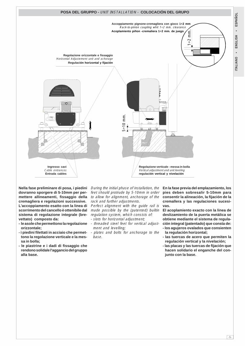
POSA DEL GRUPPO - UNIT INSTALLATION - COLOCACIÓN DEL GRUPO
Nella fase preliminare di posa, i piedinidovranno sporgere di 5-10mm per per-mettere allineamenti, fissaggio dellacremagliera e regolazioni successive.L'accoppiamento esatto con la linea discorrimento del cancello è ottenibile dalsistema di regolazione integrale (bre-vettato) composto da:- le asole che permettono la regolazione
orizzontale;- i piedini filettati in acciaio che permet-
tono la regolazione verticale e la mes-sa in bolla;
- le piastrine e i dadi di fissaggio cherendono solidale l'aggancio del gruppoalla base.
During the initial phase of installation, thefeet should protrude by 5-10mm in orderto allow for alignment, anchorage of therack and further adjustments.Perfect alignment with the guide rail ismade possible by the (patented) builtinregulation system, which consists of:- slots for horizontal adjustment;- threaded steel feet for vertical adjust-
ment and levelling;- plates and bolts for anchorage to the
base.
En la fase previa del emplazamiento, lospies deben sobresalir 5-10mm paraconsentir la alineación, la fijación de lacremallera y las regulaciones sucesi-vas.El acoplamiento exacto con la linea dedeslizamiento de la puerta metálica seobtiene mediante el sistema de regula-ción integral (patentado) que consta de:- los agujeros ovalados que consienten
la regulación horizontal;- las tuercas de acero que permiten la
regulación vertical y la nivelación;- las placas y las tuercas de fijación que
hacen solidario el enganche del con-junto con la base.
Regolazione orizzontale e fissaggioHorizontal Adjustement unit and achorage
Regulación horizontal y fijación
Accoppiamento pignone-cremagliera con gioco 1÷2 mmRack-to-pinion coupling whit 1÷2 mm. clearance
Acoplamiento piñon -cremaliera 1÷2 mm. de juego
Regolazione verticale - messa in bollaVertical adjustment and unit levelingregulación vertical y nivelación
Ingresso caviCable entrancesEntrada cables
-6-
ITA
LIA
NO
•
EN
GLI
SH
•
ES
PAÑ
OL FISSAGGIO CREMAGLIERA - ATTACHING THE RACK/LIMIT - FIJACIÓN DE LA CREMALLERA
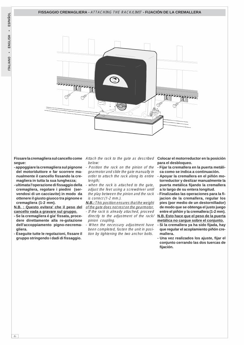
Fissare la cremagliera sul cancello comesegue:- appoggiare la cremagliera sul pignone
del motoriduttore e far scorrere ma-nualmente il cancello fissando la cre-magliera in tutta la sua lunghezza;
- ultimata l'operazione di fissaggio dellacremagliera, regolare i piedini (ser-vendosi di un cacciavite) in modo daottenere il giusto giuoco tra pignone ecremagliera (1-2 mm).
N.B. : Questo evitera' che il peso delcancello vada a gravare sul gruppo.- Se la cremagliera é gia' fissata, proce-
dere direttamente alla re-golazionedell'accoppiamento pigno-necrema-gliera.
- Eseguite tutte le regolazioni, fissare ilgruppo stringendo i dadi di fissaggio.
Attach the rack to the gate as describedbelow:
- Position the rack on the pinion of thegearmotor and slide the gate manually inorder to attach the rack along its entirelength;
- when the rack is attached to the gate,adjust the feet using a screwdriver untilthe play between the pinion and the rackis correct (1-2 mm.).
N.B.: This position ensures that the weightof the gate does not rest on the gearmotor.- If the rack is already attached, proceed
directly to the adjustment of the rack/pinion coupling.
- When the necessary adjustment havebeen completed, fasten the unit in posi-tion by tightening the two anchor bolts.
Colocar el motorreductor en la posiciónpara el desbloqueo.- Fijar la cremallera en la puerta metáli-
ca como se indica a continuación.- Apoyar la cremallera en el piñón mo-
torreductor y deslizar manualmente lapuerta metálica fijando la cremalleraa lo largo de su entera longitud.
- Finalizadas las operaciones para la fi-jacion de la cremallera, regular lospies (por medio de un destornillador)de modo que se obtenga el justo juegoentre el piñón y la cremallera (1-2 mm).
N.B. Esto hace que el peso de la puertametálica no cargue sobre el conjunto.- Si la cremallera ya ha sido fijada, hay
que regular el acoplamiento piñón cre-mallera.
- Una vez realizados los ajuste, fijar elconjunto cerrando las dos tuercas defijación.
-7-
ITA
LIA
NO
•
EN
GLI
SH
•
ES
PAÑ
OL
����
����
FISSAGGIO FINECORSA - ATTACHING THE SWITCH TABS - FIJACIÓN DE LA ALETAS DE TOPE
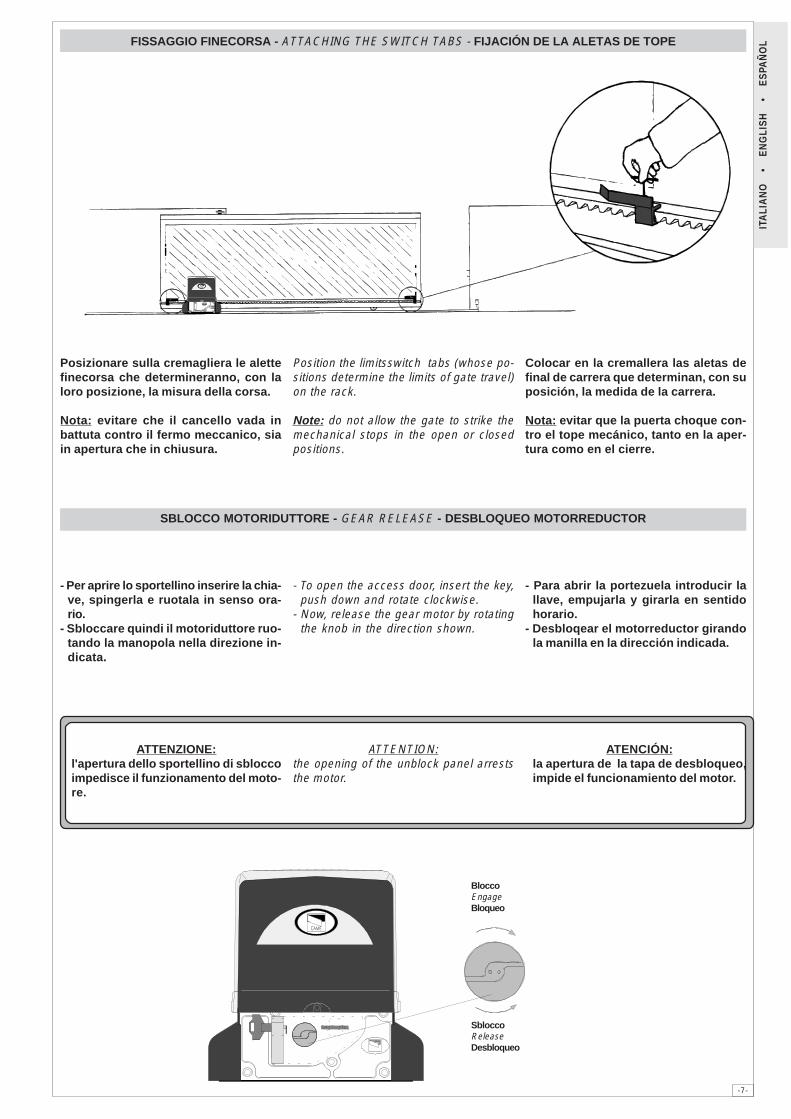
Posizionare sulla cremagliera le alettefinecorsa che determineranno, con laloro posizione, la misura della corsa.
Nota: evitare che il cancello vada inbattuta contro il fermo meccanico, siain apertura che in chiusura.
Position the limitsswitch tabs (whose po-sitions determine the limits of gate travel)on the rack.
Note: do not allow the gate to strike themechanical stops in the open or closedpositions.
Colocar en la cremallera las aletas definal de carrera que determinan, con suposición, la medida de la carrera.
Nota: evitar que la puerta choque con-tro el tope mecánico, tanto en la aper-tura como en el cierre.
SBLOCCO MOTORIDUTTORE - GEAR RELEASE - DESBLOQUEO MOTORREDUCTOR
- Per aprire lo sportellino inserire la chia-ve, spingerla e ruotala in senso ora-rio.
- Sbloccare quindi il motoriduttore ruo-tando la manopola nella direzione in-dicata.
- To open the access door, insert the key,push down and rotate clockwise.
- Now, release the gear motor by rotatingthe knob in the direction shown.
- Para abrir la portezuela introducir lallave, empujarla y girarla en sentidohorario.
- Desbloqear el motorreductor girandola manilla en la dirección indicada.
ATTENZIONE:l'apertura dello sportellino di sbloccoimpedisce il funzionamento del moto-re.
ATTENTION:the opening of the unblock panel arreststhe motor.
ATENCIÓN:la apertura de la tapa de desbloqueo,impide el funcionamiento del motor.
BloccoEngageBloqueo
SbloccoReleaseDesbloqueo
CANCELLI AUTOMATICI
CAME LOMBARDIA S.R.L.______COLOGNO M. (MI) (+39) 02 26708293 (+39) 02 25490288
CAME SUD S.R.L. ___________________NAPOLI (+39) 081 7524455 (+39) 081 7529109
CAME (AMERICA) L.L.C.____________MIAMI (FL) (+1) 305 5930227 (+1) 305 5939823
CAME AUTOMATISMOS S.A__________MADRID (+34) 091 5285009 (+34) 091 4685442
CAMEBELGIUM NU-SA_______________LESSINES (+32) 068 333014 (+32) 068 338019
CAME FRANCE S.A.____NANTERRE CEDEX (PARIS) (+33) 01 46130505 (+33) 01 46130500
CAME GMBH________KORNTAL BEI (STUTTGART) (+49) 07 11839590 (+49) 07 118395925
CAME GMBH____________SEEFELD BEI (BERLIN) (+49) 03 33988390 (+49) 03 339885508
CAME PL SP.ZO.O______________WARSZAWA (+48) 022 8365076 (+48) 022 8369920
CAME UNITED KINGDOM LTD___NOTTINGHAM (+44) 01159 210430 (+44) 01159 210431
CAME CANCELLI AUTOMATICI S.P.A.DOSSON DI CASIER (TREVISO)
(+39) 0422 4940 (+39) 0422 4941
SISTEMA QUALITÀCERTIFICATO
ASSISTENZA TECNICA
NUMERO VERDE
800 295830
WEB
www.came.it E-MAIL
Tutti i dati sono stati controllati con la massima cura. Non ci assumiamo comunquealcuna responsabilità per eventuali errori od omissioni.
All data checked with the maximum care. However, no liability is accepted for anyerror or omission.
Todos los datos se han controlado con la máxima atención. No obstante no nosresponsabilizamos de los posibles errores u omisiones.
DICHIARAZIONE DEL FABBRICANTEAi sensi dell’Allegato II B della Direttiva Macchine 98/37/CE
I Rappresentanti della
CAME Cancelli Automatici S.p.A.via Martiri della Libertà, 1531030Dosson di Casier - Treviso - ITALYtel(+39) 0422 4940 - fax (+39) 0422 4941internet: www.came.it - e-mail: [email protected]
Dichiarano sotto la propria responsabilità che i/il prodotto/i denominato/i ...
… sono conformi alle disposizioni legislative Nazionali che traspongono le seguenti DirettiveComunitarie (dove specificatamente applicabili):
DIRETTIVA MACCHINE 98/37/CEDIRETTIVA BASSA TENSIONE 73/23/CEE - 93/68/CEEDIRETTIVA COMPATIBILITÀ ELETTROMAGNETICA 89/336/CEE - 92/31/CEEDIRETTIVA R&TTE 1999/5/CE
Inoltre, dichiara che il/i prodotto/i, oggetto della presente dichiarazione, sono costruiti nel rispettodelle seguenti principali norme armonizzate:
EN 292 PARTE 1ª E 2ª SICUREZZA DEL MACCHINARIO.EN 12453 CHIUSURE INDUSTRIALI, COMMERCIALI …EN 12445 CHIUSURE INDUSTRIALI, COMMERCIALI …EN 60335 - 1 SICUREZZA NEGLI APPARECCHI AD USO DOMESTICO ...EN 60204 - 1 SICUREZZA DEL MACCHINARIO.EN 50081 - 1 E 2 COMPATIBILITÀ ELETTROMAGNETICA.EN 50082 - 1 E 2 COMPATIBILITÀ ELETTROMAGNETICA.
AVVERTENZA IMPORTANTE!È vietato mettere in servizio il/i prodotto/i, oggetto della presente dichiarazione, prima delcompletamento e/o incorporamento, in totale conformità alle disposizioni della DirettivaMacchine 98/37/CE
Firma dei Rappresentanti
Documentazioni tecniche specifiche dei prodotti sono disponibili a richiesta!
Data della presente dichiarazione 07/12/2001
Also, they furthermore represent and warrant that the product/s that are the subject of the presentDeclaration are manufactured in the respect of the following main harmonized provisions:
EN 292 PART 1 AND 2 MACHINERY SAFETY.EN 12453 INDUSTRIAL, COMMERCIAL AND OTHER CLOSING MECHANISMS.EN 12445 INDUSTRIAL, COMMERCIAL AND OTHER CLOSING MECHANISMS.EN 60335 - 1 SAFETY IN APPARATUSES FOR HOME USE.EN 60204 - 1 MACHINERY SAFETY.EN 50081 - 1 AND 2 ELECTROMAGNETIC COMPATIBILITY.EN 50082 - 1 AND 2 ELECTROMAGNETIC COMPATIBILITY.
IMPORTANT CAUTION!It is forbidden to market/use product/s that are the subject of this declaration before completing and/or incorporating them in total compliance with the provisions of Machinery Directive 98/37/CE
Signatures of the Representatives
Specific technical documentation on the products is available on request!
Date of the present declaration 07/12/2001
MANUFACTURER’S DECLARATION As per Enclosure II B of Machinery Directive 98/37/CE
The representatives of
CAME Cancelli Automatici S.p.A.via Martiri della Libertà, 1531030 Dosson di Casier - Treviso - ITALYtel (+39) 0422 4940 - fax (+39) 0422 4941internet: www.came.it - e-mail: [email protected]
Hereby declare, under their own respons ibility, that the product/s called ...
… comply with the Italian National Legal Provisions that transpose thefollowing Community Directives (where specifically applicable):
MACHINERY DIRECTIVE 98/37/CELOW VOLTAGE DIRECTIVE 73/23/EEC - 93/68/EECLECTROMAGNETIC COMPATIBILITY DIRECTIVE 89/336/EEC - 92/31/EECR&TTE DIRECTIVE 1999/5/CE
DECLARACION DEL FABRICANTEDe conformidad con el Anexo II B de la Directiva de Máquinas 98/37/CE
Fecha de la presente declaración 07/12/2001Adjunta a la documentación técnica (el original de la Declaración está disponible previa petición)
Los Representantes de la compañía
CAME Cancelli Automatici S.p.A.via Martiri della Libertà, 1531030 Dosson di Casier - Treviso - ITALYtel (+39) 0422 4940 - fax (+39) 0422 4941internet: www.came.it - e-mail: [email protected] bajo su responsabilidad que el/los producto/s denominado/s ...
… cumplen con las disposiciones legislativas nacionales que trasponen las siguientesDirectivas Comunitarias (donde específicamente aplicables):
DIRECTIVA DE MÁQUINAS 98/37/CEDIRECTIVA DE BAJA TENSIÓN 73/23/CEE - 93/68/CEEDIRECTIVA DE COMPATIBILIDAD ELECTROMAGNÉTICA 89/336/CEE - 92/31/CEEDIRECTIVA R&TTE 1999/5/CE
Los productos objeto de esta declaración están fabricados respetando las siguientes normasarmonizadas:
EN 292 PARTE 1ª Y 2ª SEGURIDAD DE LAS MÁQUINAS.EN 12453 CIERRES INDUSTRIALES, COMERCIALES …EN 12445 CIERRES INDUSTRIALES, COMERCIALES …EN 60335 - 1 SEGURIDAD DE LOS APARATOS PARA USO DOMÉSTICO...EN 60204 - 1 SEGURIDAD DE LAS MÁQUINAS.EN 50081 - 1 E 2 COMPATIBILIDAD ELECTROMAGNÉTICA.EN 50082 - 1 E 2 COMPATIBILIDAD ELECTROMAGNÉTICA.
AVVERTENZA IMPORTANTE!Está prohibido hacer uso de el/los producto/s, objeto de la presente declaración antes de completarlo/s y/o incorporarlo/s en total conformidad a las disposiciones de la Directiva de Máquinas 98/37/CE.
Firma de los Representantes
Documentación técnica específica de los productos está disponible previa petición
Enclosed with the technical documentation (the original copy of the Declaration is available on request)
Allegata alla documentazione tecnica (l’originale della Dichiarazione è disponibile a richiesta)
RESPONSABILE TECNICOSig. Gianni Michielan
PRESIDENTESig. Paolo Menuzzo
TECHNICAL MANAGERMr. Gianni Michielan
MANAGING DIRECTORMr. Paolo Menuzzo
RESPONSABLE TÉCNICOSr. Gianni Michielan
PRESIDENTESr. Paolo Menuzzo
BXA • BXB
B4336 • B4337 • CCT • CGIU • CGZ • CGZF • CGZSBRC5 • BRC10 • BRC15 • BRCP • BSF • R001
BXA • BXB
B4336 • B4337 • CCT • CGIU • CGZ • CGZF • CGZSBRC5 • BRC10 • BRC15 • BRCP • BSF • R001
BXA • BXB
B4336 • B4337 • CCT • CGIU • CGZ • CGZF • CGZSBRC5 • BRC10 • BRC15 • BRCP • BSF • R001
-1-
DocumentazioneTecnica
S18rev. 1.102/2001
© CAMECANCELLI
AUTOMATICI
319S18
SCHEDA COMANDOCONTROL BOARDCARTE DE COMMANDESTEUERPLATINETARJETA DE MANDO
SERIE Z | Z SERIES / SÉRIE Z | BAUREIHE Z | SERIE Z
ZBX6CANCELLI AUTOMATICI
CARATTERISTICHE GENERALIITALIANO
� � � � � � � � � � � � � � � � � � � � � � � � � � � �
� � � �
� �
��������
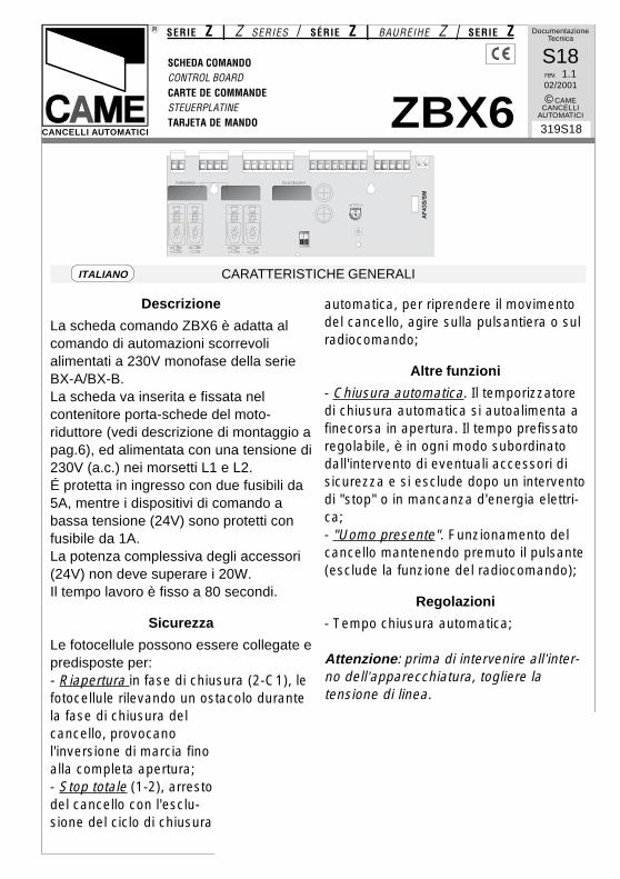
Descrizione
La scheda comando ZBX6 è adatta alcomando di automazioni scorrevolialimentati a 230V monofase della serieBX-A/BX-B.La scheda va inserita e fissata nelcontenitore porta-schede del moto-riduttore (vedi descrizione di montaggio apag.6), ed alimentata con una tensione di230V (a.c.) nei morsetti L1 e L2.É protetta in ingresso con due fusibili da5A, mentre i dispositivi di comando abassa tensione (24V) sono protetti confusibile da 1A.La potenza complessiva degli accessori(24V) non deve superare i 20W.Il tempo lavoro è fisso a 80 secondi.
Sicurezza
Le fotocellule possono essere collegate epredisposte per:- Riapertura in fase di chiusura (2-C1), lefotocellule rilevando un ostacolo durantela fase di chiusura delcancello, provocanol'inversione di marcia finoalla completa apertura;- Stop totale (1-2), arrestodel cancello con l'esclu-sione del ciclo di chiusura
automatica, per riprendere il movimentodel cancello, agire sulla pulsantiera o sulradiocomando;
Altre funzioni
- Chiusura automatica. Il temporizzatoredi chiusura automatica si autoalimenta afinecorsa in apertura. Il tempo prefissatoregolabile, è in ogni modo subordinatodall'intervento di eventuali accessori disicurezza e si esclude dopo un interventodi "stop" o in mancanza d'energia elettri-ca;- "Uomo presente". Funzionamento delcancello mantenendo premuto il pulsante(esclude la funzione del radiocomando);
Regolazioni
- Tempo chiusura automatica;
Attenzione: prima di intervenire all’inter-no dell’apparecchiatura, togliere latensione di linea.
-2-
GENERAL CHARACTERISTICSENGLISH
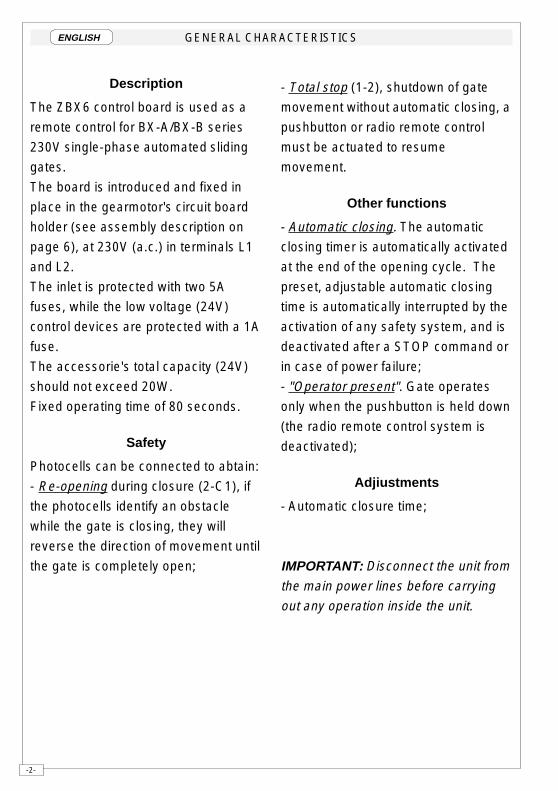
Description
The ZBX6 control board is used as a
remote control for BX-A/BX-B series
230V single-phase automated sliding
gates.
The board is introduced and fixed in
place in the gearmotor's circuit board
holder (see assembly description on
page 6), at 230V (a.c.) in terminals L1
and L2.
The inlet is protected with two 5A
fuses, while the low voltage (24V)
control devices are protected with a 1A
fuse.
The accessorie's total capacity (24V)
should not exceed 20W.
Fixed operating time of 80 seconds.
Safety
Photocells can be connected to abtain:
- Re-opening during closure (2-C1), if
the photocells identify an obstacle
while the gate is closing, they will
reverse the direction of movement until
the gate is completely open;
- Total stop (1-2), shutdown of gate
movement without automatic closing, a
pushbutton or radio remote control
must be actuated to resume
movement.
Other functions
- Automatic closing. The automatic
closing timer is automatically activated
at the end of the opening cycle. The
preset, adjustable automatic closing
time is automatically interrupted by the
activation of any safety system, and is
deactivated after a STOP command or
in case of power failure;
- "Operator present". Gate operates
only when the pushbutton is held down
(the radio remote control system is
deactivated);
Adjiustments
- Automatic closure time;
IMPORTANT: Disconnect the unit from
the main power lines before carrying
out any operation inside the unit.
-6-
DESCRIZIONE DI MONTAGGIO - ASSEMBLY DESCRIPTION - DESCRIPTION DU MONTAGEMONTAGEANLEITUNG - DESCRIPTIÓN DEL MONTAJE
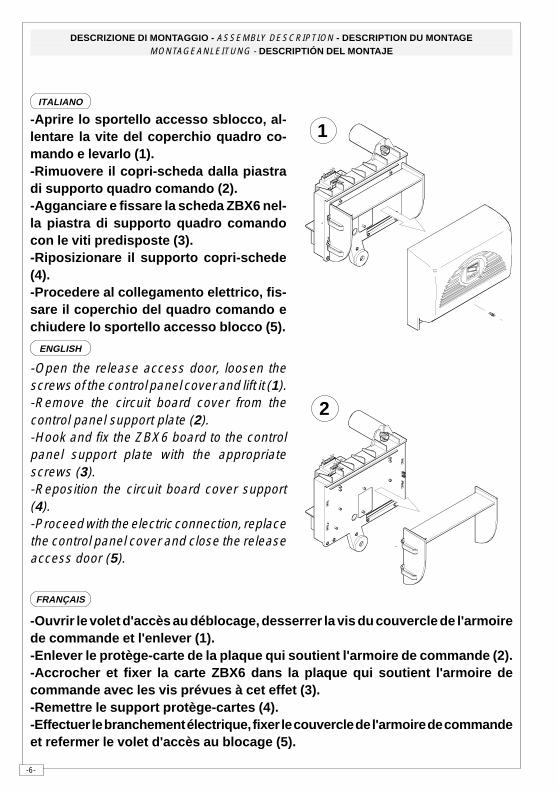
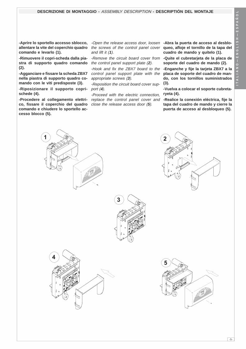
-Aprire lo sportello accesso sblocco, al-lentare la vite del coperchio quadro co-mando e levarlo (1).-Rimuovere il copri-scheda dalla piastradi supporto quadro comando (2).-Agganciare e fissare la scheda ZBX6 nel-la piastra di supporto quadro comandocon le viti predisposte (3).-Riposizionare il supporto copri-schede(4).-Procedere al collegamento elettrico, fis-sare il coperchio del quadro comando echiudere lo sportello accesso blocco (5).
-Open the release access door, loosen thescrews of the control panel cover and lift it (1).-Remove the circuit board cover from thecontrol panel support plate (2).-Hook and fix the ZBX6 board to the controlpanel support plate with the appropriatescrews (3).-Reposition the circuit board cover support(4).-Proceed with the electric connection, replacethe control panel cover and close the releaseaccess door (5).
-Ouvrir le volet d'accès au déblocage, desserrer la vis du couvercle de l'armoirede commande et l'enlever (1).-Enlever le protège-carte de la plaque qui soutient l'armoire de commande (2).-Accrocher et fixer la carte ZBX6 dans la plaque qui soutient l'armoire decommande avec les vis prévues à cet effet (3).-Remettre le support protège-cartes (4).-Effectuer le branchement électrique, fixer le couvercle de l'armoire de commandeet refermer le volet d'accès au blocage (5).
ITALIANO
ENGLISH
FRANÇAIS
1
2
-7-
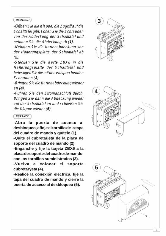
3-Öffnen Sie die Klappe, die Zugriff auf dieSchalttafel gibt. Lösen Sie die Schraubenvon der Abdeckung der Schalttafel undnehmen Sie die Abdeckung ab (1).-Nehmen Sie die Kartenabdeckung vonder Halterungsplatte der Schalttafel ab(2).-Stecken Sie die Karte ZBX6 in dieHalterungsplatte der Schalttafel undbefestigen Sie die mit den entsprechendenSchrauben (3).-Bringen Sie die Kartenabdeckung wiederan (4).-Führen Sie den Stromanschluß durch.Bringen Sie dann die Abdeckung wiederauf der Schalttafel an und schließen Siedie Klappe wieder (5).
-Abra la puerta de acceso aldesbloqueo, afloje el tornillo de la tapadel cuadro de mando y quítelo (1).-Quite el cubretarjeta de la placa desoporte del cuadro de mando (2).-Enganche y fije la tarjeta ZBX6 a laplaca de soporte del cuadro de mando,con los tornillos suministrados (3).-Vuelva a colocar el soportecubretaryeta (4).-Realice la conexión eléctrica, fije latapa del cuadro de mando y cierre lapuerta de acceso al desbloqueo (5).
4
5
ESPANOL
DEUTSCH
-8-
SCHEDA BASE - MOTHERBOARD - CARTE BASE - GRUNDPLATINE - TARJETA BASE
� � � � � � � � � � � � � � � � � � � � � � � � � � � �
� � � �
� �
��������
�
� �
�
�
� �
�
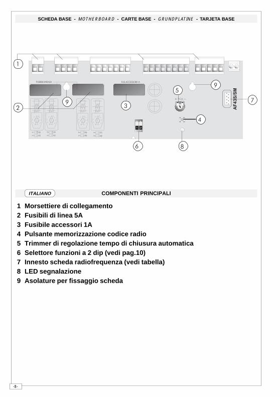
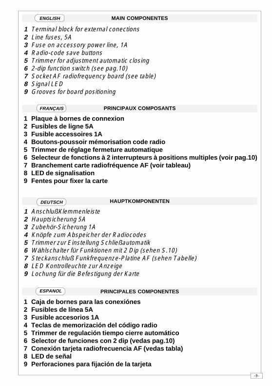
COMPONENTI PRINCIPALI
1 Morsettiere di collegamento 2 Fusibili di linea 5A 3 Fusibile accessori 1A 4 Pulsante memorizzazione codice radio 5 Trimmer di regolazione tempo di chiusura automatica 6 Selettore funzioni a 2 dip (vedi pag.10) 7 Innesto scheda radiofrequenza (vedi tabella) 8 LED segnalazione 9 Asolature per fissaggio scheda
ITALIANO
-9-
HAUPTKOMPONENTEN
1 AnschlußKlemmenleiste 2 Hauptsicherung 5A 3 Zubehör-Sicherung 1A 4 Knöpfe zum Abspeicher der Radiocodes 5 Trimmer zur Einstellung Schließautomatik 6 Wählschalter für Funktionen mit 2 Dip (sehen S.10) 7 Steckanschluß Funkfrequenze-Platine AF (sehen Tabelle) 8 LED Kontrolleuchte zur Anzeige 9 Lochung für die Befestigung der Karte
PRINCIPALES COMPONENTES
1 Caja de bornes para las conexiónes 2 Fusibles de línea 5A 3 Fusible accesorios 1A 4 Teclas de memorización del código radio 5 Trimmer de regulación tiempo cierre automático 6 Selector de funciones con 2 dip (vedas pag.10) 7 Conexión tarjeta radiofrecuencia AF (vedas tabla) 8 LED de señal 9 Perforaciones para fijación de la tarjeta
MAIN COMPONENTES
1 Terminal block for external conections 2 Line fuses, 5A 3 Fuse on accessory power line, 1A 4 Radio-code save buttons 5 Trimmer for adjustment automatic closing 6 2-dip function switch (see pag.10) 7 Socket AF radiofrequency board (see table) 8 Signal LED 9 Grooves for board positioning
PRINCIPAUX COMPOSANTS
1 Plaque à bornes de connexion 2 Fusibles de ligne 5A 3 Fusible accessoires 1A 4 Boutons-poussoir mémorisation code radio 5 Trimmer de réglage fermeture automatique 6 Selecteur de fonctions à 2 interrupteurs à positions multiples (voir pag.10) 7 Branchement carte radiofréquence AF (voir tableau) 8 LED de signalisation 9 Fentes pour fixer la carte
ENGLISH
FRANÇAIS
ESPANOL
DEUTSCH
-10-
�� � � ��� ������ ������������ �� ����
������
1 2
AF
43S
/SM
L1 L2 U V W E1 11 1 2 7 C110 FA FC F
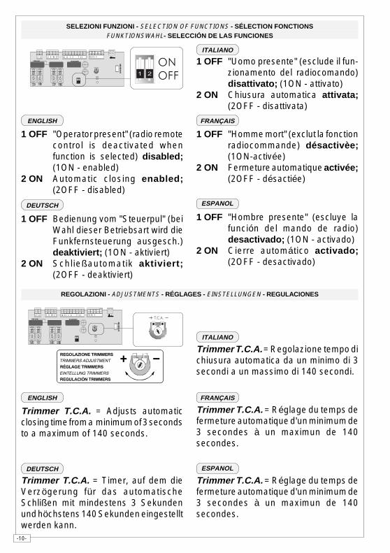
1 OFF "Uomo presente" (esclude il fun-zionamento del radiocomando)disattivato; (1ON - attivato)
2 ON Chiusura automatica attivata;(2OFF - disattivata)
REGOLAZIONI - ADJUSTMENTS - RÉGLAGES - EINSTELLUNGEN - REGULACIONES
Trimmer T.C.A. = Regolazione tempo dichiusura automatica da un minimo di 3secondi a un massimo di 140 secondi.
SELEZIONI FUNZIONI - SELECTION OF FUNCTIONS - SÉLECTION FONCTIONSFUNKTIONSWAHL- SELECCIÓN DE LAS FUNCIONES
1 OFF "Operator present" (radio remotecontrol is deactivated whenfunction is selected) disabled;(1ON - enabled)
2 ON Automatic closing enabled;(2OFF - disabled)
1 OFF "Homme mort" (exclut la fonctionradiocommande) désactivèe;(1ON-activée)
2 ON Fermeture automatique activée;(2OFF - désactiée)
1 OFF Bedienung vom "Steuerpul" (beiWahl dieser Betriebsart wird dieFunkfernsteuerung ausgesch.)deaktiviert; (1ON - aktiviert)
2 ON Schließautomatik aktiviert;(2OFF - deaktiviert)
1 OFF "Hombre presente" (escluye lafunción del mando de radio)desactivado; (1ON - activado)
2 ON Cierre automático activado;(2OFF - desactivado)
Trimmer T.C.A. = Adjusts automaticclosing time from a minimum of 3 secondsto a maximum of 140 seconds.
Trimmer T.C.A. = Timer, auf dem dieVerzögerung für das automatischeSchlißen mit mindestens 3 Sekundenund höchstens 140 Sekunden eingestelltwerden kann.
Trimmer T.C.A. = Réglage du temps defermeture automatique d'un minimum de3 secondes à un maximun de 140secondes.
Trimmer T.C.A. = Réglage du temps defermeture automatique d'un minimum de3 secondes à un maximun de 140secondes.
��
�� �
�� � � ��� ������ ������������ �� ����
������
1 2
AF
43S
/SM
L1 L2 U V W E1 11 1 2 7 C110 FA FC F
������������ ���
���������������
����������� ���
������ �������
�������������� ���
� � � �
ENGLISH FRANÇAIS
ESPANOL
ITALIANO
DEUTSCH
ENGLISH FRANÇAIS
ESPANOL
ITALIANO
DEUTSCH
-11-
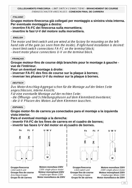
Gruppo motore-finecorsa già collegati per montaggio a sinistra vista interna.Per eventuale montaggio a destra:- invertire FA-FC dei finecorsa sulla morsettiera;- invertire le fasi U-V del motore sulla morsettiera.
The motor and limit switch unit are wired at the factory for mounting on the left-hand side of the gate (as seen from the inside). If right-hand installation is desired:- invert limit switch connections FA-FC on the terminal block;- invert motor phase connections U-V on the terminal block.
Groupe moteur-fins de course déjà branchés pour le montage à gauche -vue de l'intérieur.Pour un éventuel montage à droite:- inverser FA-FC des fins de course sur la plaque à bornes;- inverser les phases U-V du moteur sur la plaque à bornes.
Das Motor-Anschlag-Aggregat schon für die Montage auf der linken Seiteangeschlossen, interne Ansicht.Für eine eventuelle Montage auf der rechten Seite:- die Öffnungs- und Schließungsphasen auf dem Klemmbrett invertieren;- die U-V Phasen des Motors auf dem Klemmen tauschen.
Grupo motor-fin de carrera ya conectados para el montaje a la izquierdavista interior.Para el eventual montaje a la derecha:- invertir FA-FC de los fines de carrera en el cuadro de bornes;- invertir las fases U-V del motor en el cuadro de bornes.
COLLEGAMENTO FINECORSA - LIMIT SWITCH CONNECTIONS - BRANCHEMENT DE COURSEENDAUSSCHALTER-ANSCHLUSS - CONEXION FINAL DE CARRERA
Gruppo finecorsaLimit switch unitGroupe fins de courseAnschlag-GruppeGrupo fin de carrera
Motore monofase 230V230V single-phase motor
Moteur monophasé 230VEinphasiger Motor 230V
Motor monofásico de 230V
Motore monofase 230V230V single-phase motor
Moteur monophasé 230VEinphasiger Motor 230V
Motor monofásico de 230V
Gruppo finecorsaLimit switch unit
Groupe fins de courseAnschlag-Gruppe
Grupo fin de carrera
NC NC
U W V
CO
M
FCFA F
M
NC
NC
U W VFCFA F
M
CO
M
ENGLISH
FRANÇAIS
ESPANOL
ITALIANO
DEUTSCH
-12-
COLLEGAMENTI ELETTRICI - ELECTRICAL CONNECTIONS - BRANCHEMENTS ÉLECTRIQUES ELEKRISCHE ANSCHLÜSSE - CONEXIONES ELÉCTRICAS
�
��
�
�
�
��
��
��
��
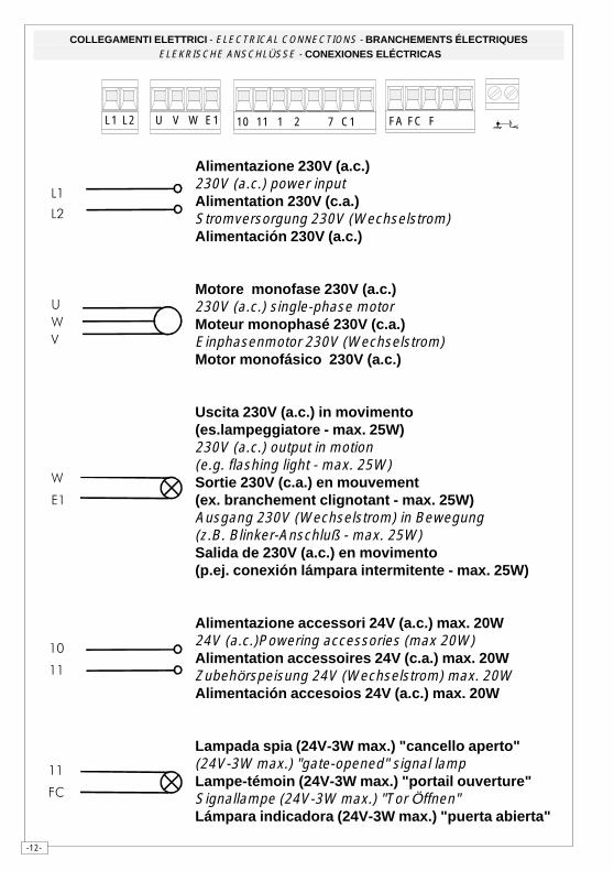
Alimentazione 230V (a.c.)230V (a.c.) power inputAlimentation 230V (c.a.)Stromversorgung 230V (Wechselstrom)Alimentación 230V (a.c.)
Motore monofase 230V (a.c.)230V (a.c.) single-phase motorMoteur monophasé 230V (c.a.)Einphasenmotor 230V (Wechselstrom)Motor monofásico 230V (a.c.)
Uscita 230V (a.c.) in movimento(es.lampeggiatore - max. 25W)230V (a.c.) output in motion(e.g. flashing light - max. 25W)Sortie 230V (c.a.) en mouvement(ex. branchement clignotant - max. 25W)Ausgang 230V (Wechselstrom) in Bewegung(z.B. Blinker-Anschluß - max. 25W)Salida de 230V (a.c.) en movimento(p.ej. conexión lámpara intermitente - max. 25W)
Alimentazione accessori 24V (a.c.) max. 20W24V (a.c.)Powering accessories (max 20W)Alimentation accessoires 24V (c.a.) max. 20WZubehörspeisung 24V (Wechselstrom) max. 20WAlimentación accesoios 24V (a.c.) max. 20W
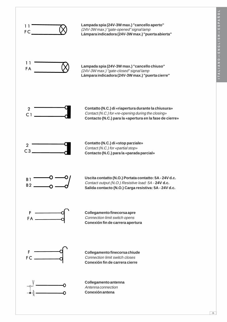
Lampada spia (24V-3W max.) "cancello aperto"(24V-3W max.) "gate-opened" signal lampLampe-témoin (24V-3W max.) "portail ouverture"Signallampe (24V-3W max.) "Tor Öffnen"Lámpara indicadora (24V-3W max.) "puerta abierta"
��
�
L1 L2 U V W E1 11 1 2 7 C110 FA FC F
-13-
��
�
��
��
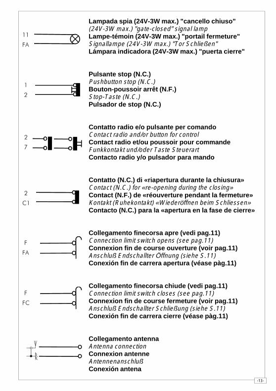
Lampada spia (24V-3W max.) "cancello chiuso"(24V-3W max.) "gate-closed" signal lampLampe-témoin (24V-3W max.) "portail fermeture"Signallampe (24V-3W max.) "Tor Schließen"Lámpara indicadora (24V-3W max.) "puerta cierre"
Pulsante stop (N.C.)Pushbutton stop (N.C.)Bouton-poussoir arrêt (N.F.)Stop-Taste (N.C.)Pulsador de stop (N.C.)
Contatto radio e/o pulsante per comandoContact radio and/or button for controlContact radio et/ou poussoir pour commandeFunkkontakt und/oder Taste SteuerartContacto radio y/o pulsador para mando
Contatto (N.C.) di «riapertura durante la chiusura»Contact (N.C.) for «re-opening during the closing»Contact (N.F.) de «réouverture pendant la fermeture»Kontakt (Ruhekontakt) «Wiederöffnen beim Schliessen»Contacto (N.C.) para la «apertura en la fase de cierre»
Collegamento finecorsa apre (vedi pag.11)Connection limit switch opens (see pag.11)Connexion fin de course ouverture (voir pag.11)Anschluß Endschallter Öffnung (siehe S.11)Conexión fin de carrera apertura (véase pàg.11)
Collegamento finecorsa chiude (vedi pag.11)Connection limit switch closes (see pag.11)Connexion fin de course fermeture (voir pag.11)Anschluß Endschallter Schließung (siehe S.11)Conexión fin de carrera cierre (véase pàg.11)
Collegamento antennaAntenna connectionConnexion antenneAntennenanschlußConexión antena
��
��
�
�
��
��
�
�
-14-
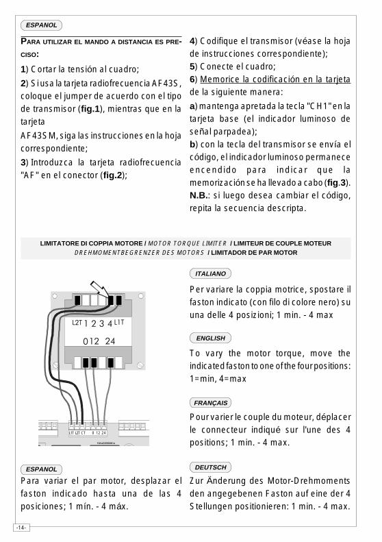
PARA UTILIZAR EL MANDO A DISTANCIA ES PRE-CISO:
1) Cortar la tensión al cuadro;
2) Si usa la tarjeta radiofrecuencia AF43S,coloque el jumper de acuerdo con el tipode transmisor (fig.1), mientras que en latarjeta
AF43SM, siga las instrucciones en la hojacorrespondiente;
3) Introduzca la tarjeta radiofrecuencia"AF" en el conector (fig.2);
LIMITATORE DI COPPIA MOTORE / MOTOR TORQUE LIMITER / LIMITEUR DE COUPLE MOTEURDREHMOMENTBEGRENZER DES MOTORS / LIMITADOR DE PAR MOTOR
Per variare la coppia motrice, spostare ilfaston indicato (con filo di colore nero) suuna delle 4 posizioni; 1 min. - 4 max
To vary the motor torque, move theindicated faston to one of the four positions:1=min, 4=max
Pour varier le couple du moteur, déplacerle connecteur indiqué sur l'une des 4positions; 1 min. - 4 max.
Zur Änderung des Motor-Drehmomentsden angegebenen Faston auf eine der 4Stellungen positionieren: 1 min. - 4 max.
Para variar el par motor, desplazar elfaston indicado hasta una de las 4posiciones; 1 mín. - 4 máx.
� � � ���� ���
� ����
������������ ����
L1T 0 12 24L2T CT
4) Codifique el transmisor (véase la hojade instrucciones correspondiente);5) Conecte el cuadro;6) Memorice la codificación en la tarjetade la siguiente manera:
a) mantenga apretada la tecla "CH1" en latarjeta base (el indicador luminoso deseñal parpadea);b) con la tecla del transmisor se envía elcódigo, el indicador luminoso permaneceencendido para indicar que lamemorización se ha llevado a cabo (fig.3).N.B.: si luego desea cambiar el código,repita la secuencia descripta.
ENGLISH
FRANÇAIS
ESPANOL
ITALIANO
DEUTSCH
ESPANOL
-15-
BA
COLLEGAMENTO PER 2 MOTORI ABBINATI - CONNECTIONS FOR 2 COMBINED MOTORSCONNEXIONS POUR 2 MOTEURS ACCOUPLÉS
ANSCHLUSSE FÜR 2 PARALLELGESCHALTETEN MOTOREN - CONEXIÓN PARA 2 MOTORES ACOPLADOS
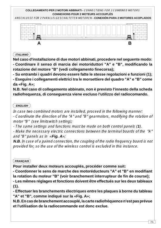
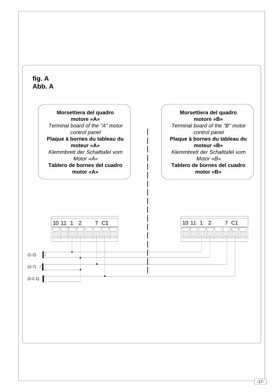
Nel caso d'installazione di due motori abbinati, procedere nel seguente modo:- Coordinare il senso di marcia dei motoriduttori "A" e "B", modificando larotazione del motore "B" (vedi collegamento finecorsa);- Su entrambi i quadri devono essere fatte le stesse regolazioni e funzioni (1);- Eseguire i collegamenti elettrici tra le morsettiere del quadro "A" e "B" comeda «Fig. A»;N.B. Nel caso di collegamento abbinato, non è previsto l'innesto della schedaradiofrequenza, di conseguenza viene escluso l'utilizzo del radiocomando.
In case two combined motors are installed, proceed in the following manner:- Coordinate the direction of the "A" and "B" gearmotors, modifying the rotation ofmotor "B" (see limitswitch setting);- The same settings and functions must be made on both control panels (1).- Make the necessary electric connections between the terminal boards of the "A"and "B" panels as in «Fig. A»;N.B. In case of a paired connection, the coupling of the radio frequency board is notprovided for, so the use of the wireless control is excluded in this instance.
Pour installer deux moteurs accouplés, procéder comme suit:- Coordonner le sens de marche des motoréducteurs "A" et "B" en modifiantla rotation du moteur "B" (voir branchement interrupteur de fin de course);- Les mêmes réglages et fonctions doivent être effectués sur les deux tableaux(1).- Effectuer les branchements électriques entre les plaques à borne du tableau"A" et "B", comme indiqué sur la «Fig. A»;N.B. En cas de branchement accouplé, la carte radiofréquence n'est pas prévueet l'utilisation de la radiocommande est donc exclue.
ITALIANO
ENGLISH
FRANÇAIS
-16-
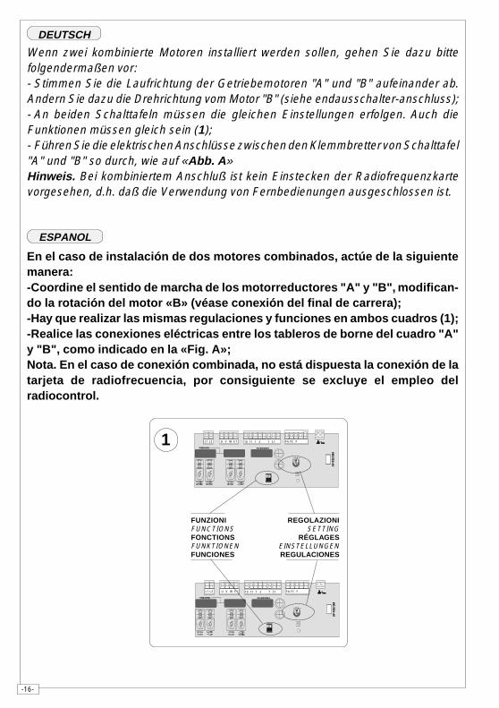
En el caso de instalación de dos motores combinados, actúe de la siguientemanera:-Coordine el sentido de marcha de los motorreductores "A" y "B", modifican-do la rotación del motor «B» (véase conexión del final de carrera);-Hay que realizar las mismas regulaciones y funciones en ambos cuadros (1);-Realice las conexiones eléctricas entre los tableros de borne del cuadro "A"y "B", como indicado en la «Fig. A»;Nota. En el caso de conexión combinada, no está dispuesta la conexión de latarjeta de radiofrecuencia, por consiguiente se excluye el empleo delradiocontrol.
Wenn zwei kombinierte Motoren installiert werden sollen, gehen Sie dazu bittefolgendermaßen vor:- Stimmen Sie die Laufrichtung der Getriebemotoren "A" und "B" aufeinander ab.Andern Sie dazu die Drehrichtung vom Motor "B" (siehe endausschalter-anschluss);- An beiden Schalttafeln müssen die gleichen Einstellungen erfolgen. Auch dieFunktionen müssen gleich sein (1);- Führen Sie die elektrischen Anschlüsse zwischen den Klemmbretter von Schalttafel"A" und "B" so durch, wie auf «Abb. A»Hinweis. Bei kombiniertem Anschluß ist kein Einstecken der Radiofrequenzkartevorgesehen, d.h. daß die Verwendung von Fernbedienungen ausgeschlossen ist.
DEUTSCH
ESPANOL
�� � � ��� ������ ������������ �� ����
������
1 2
AF
43S
/SM
L1 L2 U V W E1 11 1 2 7 C110 FA FC F
�� � � ��� ������ ������������ �� ����
������
1 2
AF
43S
/SM
L1 L2 U V W E1 11 1 2 7 C110 FA FC F
FUNZIONIFUNCTIONSFONCTIONSFUNKTIONENFUNCIONES
REGOLAZIONISETTING
RÉGLAGESEINSTELLUNGENREGULACIONES
1
-17-
fig. AAbb. A
10 11 1 2 7 C1 10 11 1 2 7 C1
(1-2)
(2-7)
(2-C1)
Morsettiera del quadromotore «A»
Terminal board of the "A" motorcontrol panel
Plaque à bornes du tableau dumoteur «A»
Klemmbrett der Schalttafel vomMotor «A»
Tablero de bornes del cuadromotor «A»
Morsettiera del quadromotore «B»
Terminal board of the "B" motorcontrol panel
Plaque à bornes du tableau dumoteur «B»
Klemmbrett der Schalttafel vomMotor «B»
Tablero de bornes del cuadromotor «B»
-18-
ZA5
ENGLISH
PROCEDURE
A. insert an
AF card **.
B. encodetransmitter/s.
C. store code inthemotherboard.
FRANÇAIS
PROCEDURE
A. placer unecarte AF **.
B. codifier le/sémetteur/s.
C. mémoriser lacodificationsur la cartebase.
DEUTSCH
PROZEDUR
A. Stecken Sieeine Karte
AF **.
B. Codieren Sieden/dieSender.
C. Speichern Siedie Codierungauf derGrundplatine.
ITALIANO
PROCEDURA
A. inserire una
scheda AF **.
B. codificare il/i
trasmettitore/i.
C. memorizzare la
codifica sulla
scheda base.
INSTALLAZIONE DEL RADIOCOMANDO - RADIO CONTROL INSTALLATION - INSTALLATION DE LA RADIOCOMMANDE
INSTALLATION DER RADIOSTEUERUNG - INSTALACIÓN DEL RADIOMANDO
ESPANOL
PROCEDIMIENTO
A. introduciruna tarjetaAF **.
B. codificar el/lostransmisor/es.
C. memorizar lacodificaciónen la tarjetabase.
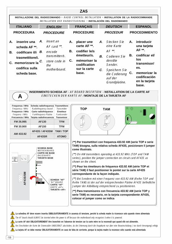
(**) Per trasmettitori con frequenza 433.92 AM (serie TOP e serieTAM) bisogna, sulla relativa scheda AF43S, posizionare il jumpercome illustrato.
(**) On AM transmitters operating at 433.92 MHz (TOP and TAMseries), position the jumper connection on circuit card AF43S asshown on the sheet.
(**) Pour les émetteurs de fréquence 433.92 AM (série TOP etsérie TAM) il faut positionner le pontet sur la carte AF43Scorrespondante de la façon indiquée.
(**) Bei Sendern mit einer Frequenz von 433.92 AM (Reihe TOP undReihe TAM) ist der auf der entsprechenden Platine AF43S befindlicheJumper der Abbildung entsprechend zu positionieren.
(**) Para transmisores con frecuencia 433.92 AM (serie TOP yserie TAM) es necesario, en la tarjeta corespondiente AF43S,colocar el jumper como se indica
TOP TAM
SCHEDA BASEMOTHERBOARDCARTE DE BASEBASISKARTETARJETA BASE
SCHEDA "AF""AF" BOARDCARTE "AF"KARTE «AF»TARJETA «AF»
La schedina AF deve essere inserita OBBLIGATORIAMENTE in assenza di tensione, perché la scheda madre la riconosce solo quando viene alimentata
The AF board should ALWAYS be inserted when the power is off because the motherboard only recognises it when it is powered.
La carte AF doit OBLIGATOIREMENT être branchée en l’absence de tension car la carte mère ne la reconnaît que quand elle est alimentée.
Vor Einschieben der Karte die Stromzufuhr UNBEDINGT abschalten, da die Erkennung durch die Hauptkarte nur über eine Neueinschaltung ( nur durch Versorgung) erfolgt.
La tarjeta AF se debe montar OBLIGATORIAMENTE en caso de falta de corriente, porque la tarjeta madre la reconoce sólo cuando está alimentada
zHM/azneuqerFzHM/ycneuqerFzHM/ecneuqerF
zHM/zneuqerFzHM/aicneucerF
azneuqerfoidaradehcSdraobycneuqerfoidaRecneuqérfoidaretraC
enitalP-zneuqerfknuFaicneucerfoidaratejraT
erotittemsarTrettimsnarT
ruettemErednesknuFrosimsnarT
599.62MF 031FA MFT
009.03MF 051FA MFT
29.334MAMS34FA/S34FA POT/MAT
RS34FA OMOTA
INSERIMENTO SCHEDA AF - AF BOARD INSERTION - NSTALLATION DE LA CARTE AFEINSTECKEN DER KARTE AF / MONTAJE DE LA TARJETA AFA
��������
-19-
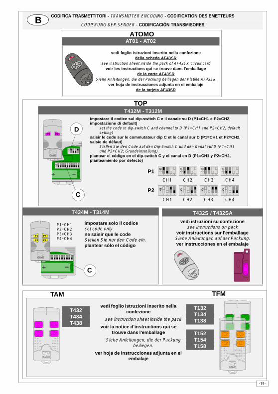
AT01 - AT02
vedi foglio istruzioni inserito nella confezionedella scheda AF43SR
see instruction sheet inside the pack of AF43SR circuit cardvoir les instructions qui se trouve dans l'emballage
de la carte AF43SRSiehe Anleitungen, die der Packung beiliegen der Platine AF43SR
ver hoja de instrucciones adjunta en el embalajede la tarjeta AF43SR
ATOMO
CODIFICA TRASMETTITORI - TRANSMITTER ENCODING - CODIFICATION DES EMETTEURS
CODIERUNG DER SENDER - CODIFICACIÓN TRANSMISORESB
vedi istruzioni su confezionesee instructions on pack
voir instructions sur l'emballageSiehe Anleitungen auf der Packung.ver instrucciones en el embalaje
T432S / T432SAT434M - T314M
impostare solo il codiceset code onlyne saisir que le codeStellen Sie nur den Code ein.plantear sólo el código
P1=CH1P2=CH2P3=CH3P4=CH4
1 2 3 4 5 6 7 8 9 10
C
P1 P2
P3 P4
TOP
impostare il codice sul dip-switch C e il canale su D (P1=CH1 e P2=CH2,impostazione di default)
set the code to dip-switch C and channel to D (P1=CH1 and P2=CH2, defaultsetting)
saisir le code sur le commutateur dip C et le canal sur D (P1=CH1 et P2=CH2,saisie de défaut)
Stellen Sie den Code auf den Dip-Switch C und den Kanal auf D (P1=CH1und P2=CH2; Grundeinstellung).
plantear el código en el dip-switch C y el canal en D (P1=CH1 y P2=CH2,planteamiento por defecto)
T432M - T312M
1 2 3 4 5 6 7 8 9 10
1 2 3 4
C
DP1 P2
P2
CH1 CH2 CH3 CH4
P1
CH1 CH2 CH3 CH41 2 3 4 1 2 3 4 1 2 3 41 2 3 4
1 2 3 4 1 2 3 4 1 2 3 4 1 2 3 4
vedi foglio istruzioni inserito nellaconfezione
see instruction sheet inside the pack
voir la notice d'instructions qui setrouve dans l'emballage
Siehe Anleitungen, die der Packungbeiliegen.
ver hoja de instrucciones adjunta en elembalaje
TAM
T132T134T138
T152T154T158
T432T434T438
TFM
-20-
CAME LOMBARDIA S.R.L.___COLOGNO M. (MI)(+39) 02 26708293 (+39) 02 25490288
CAME SUD S.R.L. _________________NAPOLI(+39) 081 752445 (+39) 081 7529109
CAME (AMERICA) L.L.C._________MIAMI (FL)(+1) 305 5930227 (+1) 305 5939823
CAME AUTOMATISMOS S.A_________MADRID(+34) 091 5285009 (+34) 091 4685442
CAME BELGIUM____________LESSINES(+32) 068 333014 (+32) 068 338019
CAME CANCELLI AUTOMATICI S.P.A.DOSSON DI CASIER (TREVISO)
(+39) 0422 (+39) 0422 490944
CANCELLI AUTOMATICI
CAME FRANCE S.A.___NANTERRE CEDEX (PARIS)(+33) 01 46130505 (+33) 01 46130500
CAME GMBH____KORNTAL BEI (STUTTGART)(+49) 07 11839590 (+49) 07 118395925
CAME GMBH________SEEFELD BEI (BERLIN)(+49) 03 33988390 (+49) 03 339885508
CAME PL SP.ZO.O_________WARSZAWA(+48) 022 8699933 (+48) 022 6399933
CAME UNITED KINGDOM LTD___NOTTINGHAM(+44) 01159 387200 (+44) 01159 382694
ASSISTENZA TECNICA
NUMERO VERDE
800 295830
WEBwww.came.it
SISTEMA QUALITÀCERTIFICATO
ITALIANO
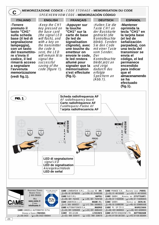
-Tenerepremuto iltasto "CH1"sulla schedabase (il led disegnalazionelampeggia),con un tastodel trasmettito-re s'invia ilcodice, il ledrimarrà accesoa segnalarel'avvenutamemorizzazione(vedi fig.1).
DEUTSCH
-Halten Sie dieTaste CH1 ander Basiskartegedrückt (dieKontrolleuchteblinkt). SendenSie den Codemit einer Tastevom Sender.DerKontrolleuchtebleibt jetzt anund zeigtdadurch daserfolgteSpeichern an(Abb.1).
ESPANOL
-Manteneroprimida latecla "CH1" enla tarjeta base(el led deseñalizaciónparpadea), conuna tecla deltransmisor seenvía elcódigo, el ledpermaneceencendidopara indicarque elalmacenamendose haefectuado(fig.1).
ENGLISH
-Keep the CH1key pressed onthe base card(the signal LEDwill flash), andwith a key onthe transmitterthe code issent, the LEDwill remain lit tosignal thesuccessfulsaving of thecode (figure 1).
FRANÇAIS
-Appuyer surla touche"CH1" sur lacarte de base(le led designalisationclignote), avecune touche duemetteur onenvoie le code,le led resteraallumé poursignaler que lamémorisations'est effectuèe(fig.1).
MEMORIZZAZIONE CODICE - CODE STORAGE - MEMORISATION DU CODESPEICHERN VOM CODE - MEMORIZACIÓN CÓDIGOC
� � � � � � � �
��������
PROG
CH1
LED di segnalazione signal LEDLED de signalisationAnzeigeleuchtdiodeLED de señal
Scheda radiofrequenza AFAF radiofrequency boardCarte radiofrèquence AFFunkfrequenz-Platine AFTarjeta radiofrecuencia AF
� � � � � � � �
��������
PROG
CH1
FIG. 1FIG. 1FIG. 1FIG. 1FIG. 1
DocumentazioneTecnica
S19rev. 2.111/2005
© CAMECANCELLI
AUTOMATICIZBX7
SERIE Z | Z SERIES / SERIE Z
SCHEDA COMANDOCONTROL BOARDTARJETA DE MANDO
ITA
LIA
NO
/EN
GL
ISH
/ES
PA
ÑO
L
319S19-1
IT
AL
IA
NO
—E
NG
LI
SH
—E
SP
AÑ
OL
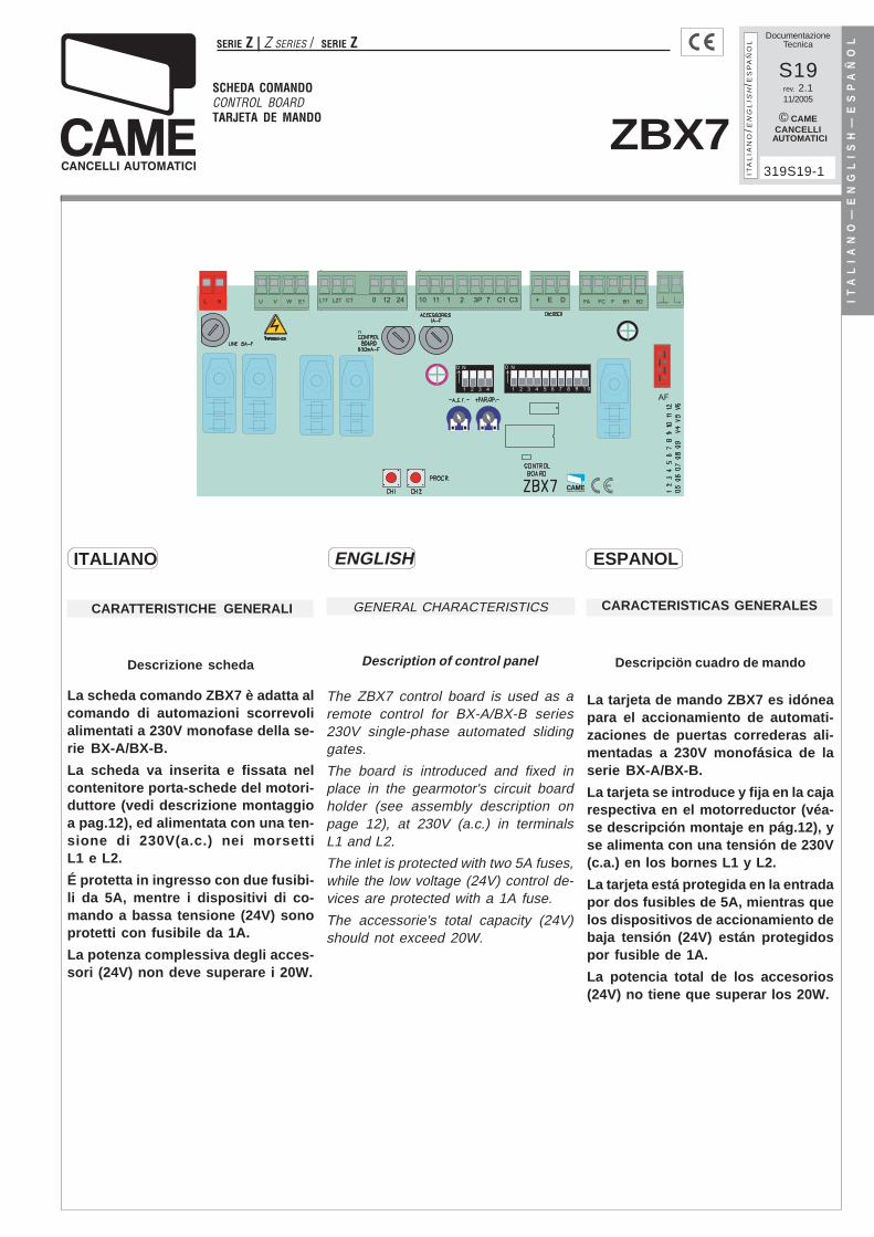
CARACTERISTICAS GENERALES
Descripciön cuadro de mando
La tarjeta de mando ZBX7 es idóneapara el accionamiento de automati-zaciones de puertas correderas ali-mentadas a 230V monofásica de laserie BX-A/BX-B.
La tarjeta se introduce y fija en la cajarespectiva en el motorreductor (véa-se descripción montaje en pág.12), yse alimenta con una tensión de 230V(c.a.) en los bornes L1 y L2.
La tarjeta está protegida en la entradapor dos fusibles de 5A, mientras quelos dispositivos de accionamiento debaja tensión (24V) están protegidospor fusible de 1A.
La potencia total de los accesorios(24V) no tiene que superar los 20W.
GENERAL CHARACTERISTICS
Description of control panel
The ZBX7 control board is used as aremote control for BX-A/BX-B series230V single-phase automated slidinggates.
The board is introduced and fixed inplace in the gearmotor's circuit boardholder (see assembly description onpage 12), at 230V (a.c.) in terminalsL1 and L2.
The inlet is protected with two 5A fuses,while the low voltage (24V) control de-vices are protected with a 1A fuse.
The accessorie's total capacity (24V)should not exceed 20W.
�CARATTERISTICHE GENERALI
Descrizione scheda
La scheda comando ZBX7 è adatta alcomando di automazioni scorrevolialimentati a 230V monofase della se-rie BX-A/BX-B.
La scheda va inserita e fissata nelcontenitore porta-schede del motori-duttore (vedi descrizione montaggioa pag.12), ed alimentata con una ten-sione di 230V(a.c.) nei morsettiL1 e L2.
É protetta in ingresso con due fusibi-li da 5A, mentre i dispositivi di co-mando a bassa tensione (24V) sonoprotetti con fusibile da 1A.
La potenza complessiva degli acces-sori (24V) non deve superare i 20W.
ENGLISH ESPANOLITALIANO
-2-
IT
AL
IA
NO
—E
NG
LI
SH
—E
SP
AÑ
OL Sicurezza
Le fotocellule possono essere col-legate e predisposte per:
- Riapertura in fase di chiusura (2-C1), le fotocellule rilevando un osta-colo durante la fase di chiusura delcancello, provocano l'inversione dimarcia fino alla completa apertura;
- Stop parziale, arresto del cancellose in movimento con conseguentepre disposizione alla chiusura auto-matica (2-C3);
- Stop totale (1-2), arresto del cancel-lo con l'esclusione del ciclo di chiu-sura automatica, per riprendere ilmovimento del cancello, agire sullapulsantiera o sul radiocomando;
Nota: Se un contatto di sicurezzanormalmente chiuso (2-C1, 2-C3, 1-2) si apre, viene segnalato dallampeggio del LED di segnalazio-ne (pag.14 - n°10);
- Rilevazione di presenza ostacolo.A motore fermo (cancello chiuso,aperto o dopo un comando di stoptotale), impedisce qualsiasi movi-mento se i dispositivi di sicurezza(es. fotocellule) rilevano un ostaco-lo;
Accessori collegabili
- Lettore ottico art.001B4336, rilevagli ostacoli durante i movimenti delcancello, nella fase di apertura ilcancello si ferma e riprende il movi-mento di chiusura dopo il conteggiodella chiusura automatica, mentrein chiusura inverte il senso di mar-cia.
Attenzione! Nella fase di chiusura,dopo tre rilevamenti consecutivi, ilcancello si fer ma in apertura e vieneesclusa la chiusura automatica, perriprendere il movimento del cancel-lo, agire sulla pulsantiera o sulradiocomando;
SafetyPhotocells can be connected to ob-
tain:
- Re-opening during closure (2-C1), ifthe photocells identify an obstacle whilethe gate is closing, they will reversethe direction of movement until the gateis completely open;
- Partial stop, shutdown of moving gate,with activation of an automatic closingcycle (2-C3);
- Total stop (1-2), shutdown of gatemovement without automatic closing;a pushbutton or radio remote controlmust be actuated to resume move-ment).
N.B: If an NC safety contact (2-C1, 2-C3, 1-2) is opened, the LED (pag.14 -n°10) will flash to indicate thisfact;
-Obstacle presencedetection. When themotor is stopped (gate is closed, openor half-open after an em ercency stopcommand), the transmitter and the con-trol pushbutton will be deactiv ated if anobstacle is detected by one of thesafety devices (for example, the photo-cells);
Accessories which can beconnected to this unit
- Item. 001B4336 optical reader, de-tects obstacles during the gate'smovement; during the opening phase,the gate stops and then begins a clos-ing movement after the automaticclosure count, whilst during closure thedirection of movement is inverted.
Warning: during closure, if obstaclesare detected three times consecutive-ly, the gate will remain open andautomatic closure will be discontinued.To resume the gate's movement, usethe push-button panel or the remotecontrol;
Seguridad
Il est possible de brancher des pho-tocellules et de les programmer pour:
- Réouverture en phase de fermeture(2-C1), les cellules photoélectriquesprovoquent l'inversion de marchejusqu'à l'ouverture complète si ellesrelèvent un obstacle durant la phasede fermeture du portail;
-Parada parcial, parada de la puertasi se encuentra en movimiento conla consiguiente predisposición alcierre automático (2-C3);
-Parada total (1-2), parada de la puer-ta excluyendo el posible ciclo de cie-rre automático, para reactivar el mo-vimiento es preciso actuar en el te-clado o en el mando a distancia;
Nota: La apertura de un contacto deseguridad normalmente cerrado (2-C1, 2-C3, 1-2) es señalada por mediodel destello LED de señalización(pàg. 14 - n° 10).
-Detección de presencia obstàculo.Con el motor parado (puerta cerra-da, abierta o en posición semi-abiertaobtenida a través de un comando destop total), anula cualquier funcióndel transmisor o del botòn en casode obstàculo detectado por los dis-positivos de seguridad (por ejem-plo: fotocélulas).
Accesorios conectables
- Lector óptico art. 001B4336, detectalos obstáculos durante los movimien-tos de la puerta; durante la aperturala puerta se detiene e inicia el movi-miento de cierre, después de la cuentadel cierre automático; mientras, quedurante el cierre, invierte la direc-ción del movimiento.
Atención: durante el cierre, tras tresdetecciones consecutivas, la puertase detiene en el movimiento de aper-tura y se desconecta el cierreautomático, para reactivar el movi-miento de la puerta, use el pulsadoro el radiocontrol;
-3-
IT
AL
IA
NO
—E
NG
LI
SH
—E
SP
AÑ
OL- Cycle lamp. The lamp which lights the
manoeuvring zone: it remains lit fromthe moment the doors begin to openuntil they are completely closed (in-cluding the time required for theautomatic closure). In case automaticclosure is not enabled, the lamp re-mains lit only during movement.
The function of the cycle lamp is ob-tained in output W-E1 only if dip switchnumbers: 1 “automatic closing” and No.6 “detect obstacle presence” are set toON (see page 16).
Other functions
- Automatic closing. The automatic clos-ing timer is automatically activated atthe end of the opening cycle. The pre-set, adjustable automatic closing timeis automatically interrupted by the acti-vation of any safety system, and isdeactivated after a STOP command orin case of power failure;
- Partial opening. Gate opening for pas-sage on foot is activated by connect-ing to the 2-3P terminal blocks and itcan be adjusted by the AP.PARZ. trim-mer. By using this function, automaticclosure varies as follows:
1) Dip 1 ON - Automatic closure acti-vated.
-after a partial opening, the closure timedoes depend on any adjustment of theTCA trimmer.
2) Dip 1 OFF - Automatic closure de-activated.
- If the TCA trimmer is set to the min-imum, after a partial opening, auto-matic closure counting does not begin;
- If the TCA trimmer is set to the max-imum, after a partial opening, closingtime is set to 8 seconds.
- "Operator present". Gate operatesonly when the pushbutton is held down(the radio remote control system isdeactivated);
-Slowing at the limit switch.
FUNCTION AVAIABLE ONLY FOR GATES WEIGH-ING UP TO 300 KG, OTHERWISE IT MUST BEDISACTIVATED
- Lámpara ciclo. Lámpara que alum-bra la zona de maniobra: se quedaencendida a partir del momento enque las hojas empiezan la aperturahasta el cierre completo (incluyendoel tiempo de cierre automático). Sino se habilita el cierre automático, elcierre permanece encendido sólo du-rante el movimiento.
El funcionamiento de la lámpara ci-clo se obtiene en la salida W-E1 sólosi los dips n°1 “cierre automático” yn°6 “detección presencia obstáculo”están colocados en ON, véasepágina 16.
Otras funciones
- Cierre automático. El temporizadorde cierre automático se autoalimen-ta en fin-de-tiempo carrera en fasede apertura. El tiempo prefijado re-gulable, sin embargo, está subordi-nado a la intervención de posiblesaccesorios de seguridad y se exclu-ye después de una intervención deparada o en caso de falta de energíaeléctrica;
- Apertura parcial. La apertura de laverja para el paso peatonal, se acti-va conectado los bprnes 2-3P y pue-de ser regulada por medio del trim-mer AP.PARZ.;
Con esta función, el cierre automá-tico se modifica de la siguiente ma-nera:
1) Dip 1 en ON «cierre automáticoactivo».
- Tras una apertura parcial, el tiem-po de cierre es dependiente de la re-gulación del trimmer TCA.
2) Dip 1 en OFF «cierre automáticodesactivado».
-Si el trimmer del TCA está regula-do al mínimo, tras una apertura par-cial no se acciona la cuenta de cie-rre automático;
- Si el trimmer del TCA está regula-do al máximo, tras una apertura par-cial, el tiempo de cierre queda fijoen 8".
- Función a "hombre presente". Fun-cionamiento de la puerta mantenien-do pulsada la tecla (excluye la fun-ción del mando a distancia);
-Desaceleraciòn en final de carrera.
FUNCIÓN DISPONIBLE SÓLO PARACANCELAS CON 300 KG DE PESO MÁXIMO,EN CASO CONTRARIO DEBE SERDESACTIVADA
- Lampada ciclo. Lampada che illu-mina la zona di manovra, rimaneaccesa dal momento in cui le anteiniziano l ’apertura fino alla comple-ta chiusura (compre so il tempo dichiusura automatica). Nel caso nonviene inserita la chiusura automati-ca, rimane accesa solo durante ilmovimento. La funzione della lam-pada ciclo se i dip n°1 “chiusuraautomati ca” e n°6 “rilevazione pre-senza ostacolo” sono posizioni inON, vedi pagina 16.
Altre funzioni
- Chiusura automatica. Il temporiz-zatore di chiusura automatica si au-toalimenta a finecorsa in apertura. Iltempo prefissato regolabile, è in ognimodo subordinato dall'intervento dieventuali accessori di sicurezza e siesclude dopo un intervento di "stop"o in mancanza d'energia elettrica.
- Apertura parziale. Apertura del can-cello per passaggio pedonale, vieneattivata collegandosi ai morsetti 2-3P ed è regolabile mediante trimmerAP.PARZ.. Con questa funzione, lachiusura automatica varia nel se-guente modo:
1) Dip 1 in ON «chiusura automaticaattivata».
- Dopo un'apertura parziale, il tem-po di chiusura è dipendente dallaregolazione del trimmer TCA.
2) Dip 1 in OFF «chiusura automati-ca disattivata».
- Se il trimmer del TCA è regolato alminimo, dopo un'apertura parzialenon parte il conteggio di chiusuraautomatica.;
- Se il trimmer del TCA è regolato almassimo, dopo un 'apertura parzia-le, il tempo di chiusura è fisso a 8secondi.
- "Uomo presente". Funzionamentodel cancello mantenendo premuto ilpulsante (esclude la funzione delradiocomando);
-Rallentamento a finecorsa.
FUNZIONE DISPONIBILE SOLO PER CANCELLICON PESO MASSIMO DI 300 KG, ALTRIMENTIDEVE ESSERE DISATTIVATA
-4-
IT
AL
IA
NO
—E
NG
LI
SH
—E
SP
AÑ
OL The gate slow down before the opening
or closing movement is completed.
Only works with the optical reader on.
After every opening and closing of thesafety door or after restoring the volt-age, the slowing function is active fromthe 2nd command onwards.
- Pre-flashing. After an opening or clos-ing command, the flasher connected tothe W-E1 flashes for 5 seconds beforebeginning the procedure;
- Closing command. Function of clos-ing the gate only, with a wire lesscontrol device connected to contact2-7, set dip 1 to ON (4- way module),see page 22;
- Opening command. Function of open-ing the gate only, with a wireless controldevice connect ed to contact 2-3P, setdip 2 to ON (4-way module), see page 22;
-Type of command:
-Open-stop-close-stop by button andtransmitter;
-Open-close by button and transmitter;
-Open only by transmitter.
Adjiustments
- Automatic closure time;
- Partial opening time.
ATTENZIONE: prima di interveni-re all'interno dell'apparecchiatu-ra, togliere la tensione di linea
IMPORTANT: Shut off the mainspower before servicing the insideof the unit.
ATENCION: antes de actuar den-tro del aparado, quitar la ten-sión de línea
Il cancello rallenta la corsa primadella completa apertura o chiusura.Funziona solo con lettore ottico in-serito.
Dopo ogni chiusura e apertura dellosportellino di sicurezza o dopo unripristino della tensione, la funzionedi rallentamento è attiva dal 2° co-mando in poi.
- Prelampeggio. Dopo un co mandodi apertura o di chiu sura, il lampeg-giatore collegato su W-E1, lampeg-gia per 5 secondi prima di iniziare lamanovra.
- Comando di chiusura. Funzione disola chiusura del can cello, con di-spositivo di co mando collegato sulcontatto 2-7, posizionare il dip 1 inON (modulo a 4 vie), vedi pagina 22;
- Comando di apertura. Funzione disola apertura del cancello, con di-spositivo collegato sul contatto 2-3P, posizionare il dip 2 in ON (modu-lo a 4 vie), vedi pagina 22;
-Tipo di comando:
-apre-stop-chiude-stop con pulsan-te e/o trasmettitore;
-apre-chiude con pulsante e/o tra-smettitore;
-solo apre per trasmettitore.
Regolazioni
- Tempo chiusura automatica;
- Tempo di apertura parziale.
La puerta desacelera la carrera antesde completar la apertura o el cierre.
Funciona sólo con lector óptico co-nectado.
Tras cada apertura o cierre de la tapade seguridad, o tras una reactiva-ción de la tensión, la función dedesaceleración está activa desde el2° mando en adelante.
- Intermitencia. Después de un man-do de apertura o cierre, la lámparaintermitente conectada en W-E1, par-padea por 5 segundos antes de co-menzar la maniobra;
- Mando de cierre. Función sólo decierre de la puerta, con dispositivode mando conectado en el contacto2-7, coloque el dip 1 en ON (módulode 4 vías), véase página 22;
- Mando de apertura. Función sólode apertura de la puerta, con dispo-sitivo de mando conectado en elcontacto 2-3P, coloque el dip 2 enON (módulo de 4 vías), véase página22;
-Tipo de mando:
-abrir-stop-cerrar-stop para botón ytransmisor;
-abrir-cerrar para botón y transmi-sor;
-sólo apertura para transmisor.
Regulaciones
- Tiempo de cierre automático;
- Tiempo de apertura parcial.
-5-
IT
AL
IA
NO
—E
NG
LI
SH
—E
SP
AÑ
OL
� �
�
�
�
DESCRIZIONE DI MONTAGGIO - ASSEMBLY DESCRIPTION - DESCRIPTIÓN DEL MONTAJE
-Abra la puerta de acceso al desblo-queo, afloje el tornillo de la tapa delcuadro de mando y quítelo (1).
-Quite el cubretarjeta de la placa desoporte del cuadro de mando (2).
-Enganche y fije la tarjeta ZBX7 a laplaca de soporte del cuadro de man-do, con los tornillos suministrados(3).
-Vuelva a colocar el soporte cubreta-ryeta (4).
-Realice la conexión eléctrica, fije latapa del cuadro de mando y cierre lapuerta de acceso al desbloqueo (5).
-Aprire lo sportello accesso sblocco,allentare la vite del coperchio quadrocomando e levarlo (1).
-Rimuovere il copri-scheda dalla pia-stra di supporto quadro comando(2).
-Agganciare e fissare la scheda ZBX7nella piastra di supporto quadro co-mando con le viti predisposte (3).
-Riposizionare il supporto copri-schede (4).
-Procedere al collegamento elettri-co, fissare il coperchio del quadrocomando e chiudere lo sportello ac-cesso blocco (5).
-Open the release access door, loosenthe screws of the control panel coverand lift it (1).
-Remove the circuit board cover fromthe control panel support plate (2).
-Hook and fix the ZBX7 board to thecontrol panel support plate with theappropriate screws (3).
-Reposition the circuit board cover sup-port (4).
-Proceed with the electric connection,replace the control panel cover andclose the release access door (5).
-6-
IT
AL
IA
NO
—E
NG
LI
SH
—E
SP
AÑ
OL
11111
1 01 01 01 01 0
1 11 11 11 11 1
3333322222
44444
55555
6666677777
88888 99999
SCHEDA BASE - MOTHERBOARD - TARJETA BASE
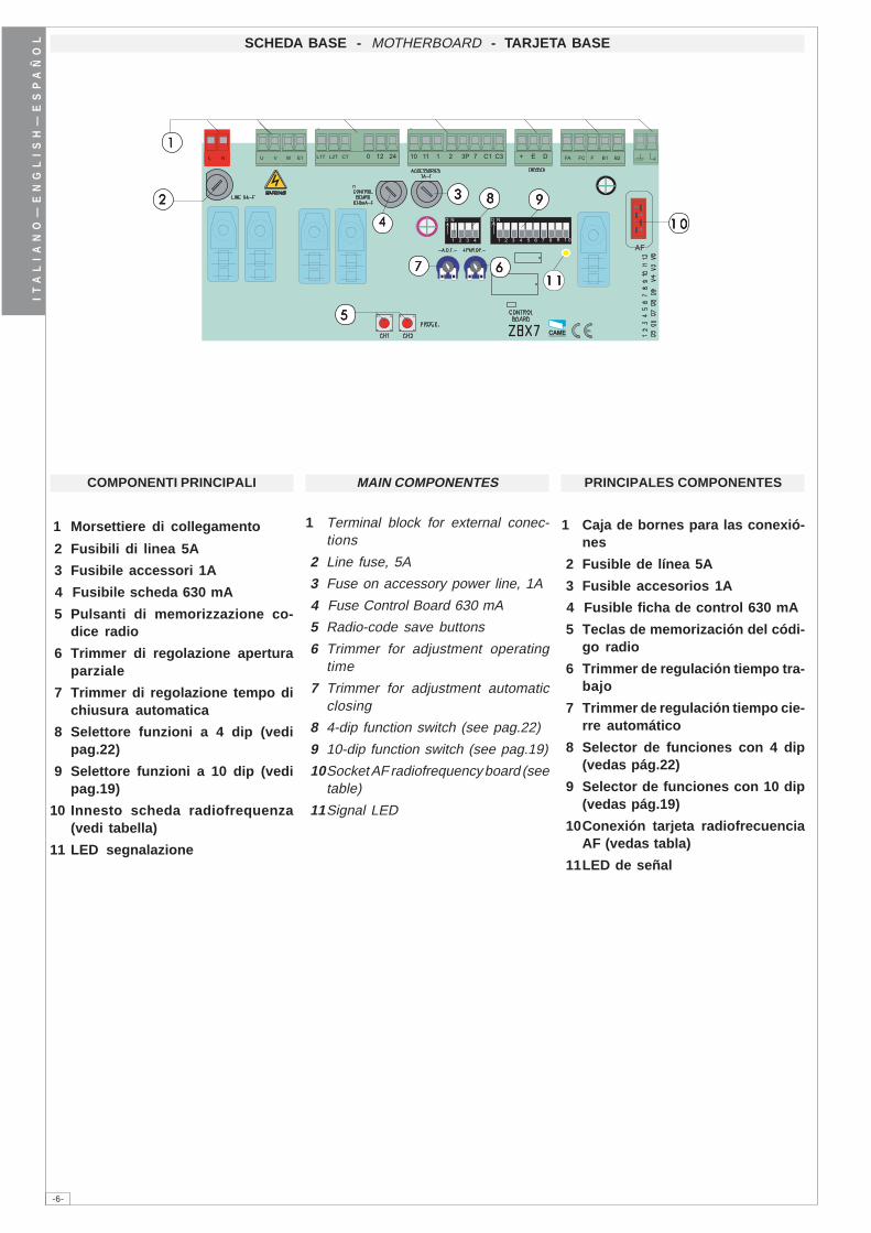
COMPONENTI PRINCIPALI
1 Morsettiere di collegamento
2 Fusibili di linea 5A
3 Fusibile accessori 1A
4 Fusibile scheda 630 mA
5 Pulsanti di memorizzazione co-dice radio
6 Trimmer di regolazione aperturaparziale
7 Trimmer di regolazione tempo dichiusura automatica
8 Selettore funzioni a 4 dip (vedipag.22)
9 Selettore funzioni a 10 dip (vedipag.19)
10 Innesto scheda radiofrequenza(vedi tabella)
11 LED segnalazione
MAIN COMPONENTES
1 Terminal block for external conec-tions
2 Line fuse, 5A
3 Fuse on accessory power line, 1A
4 Fuse Control Board 630 mA
5 Radio-code save buttons
6 Trimmer for adjustment operatingtime
7 Trimmer for adjustment automaticclosing
8 4-dip function switch (see pag.22)
9 10-dip function switch (see pag.19)
10Socket AF radiofrequency board (seetable)
11Signal LED
PRINCIPALES COMPONENTES
1 Caja de bornes para las conexió-nes
2 Fusible de línea 5A
3 Fusible accesorios 1A
4 Fusible ficha de control 630 mA
5 Teclas de memorización del códi-go radio
6 Trimmer de regulación tiempo tra-bajo
7 Trimmer de regulación tiempo cie-rre automático
8 Selector de funciones con 4 dip(vedas pág.22)
9 Selector de funciones con 10 dip(vedas pág.19)
10Conexión tarjeta radiofrecuenciaAF (vedas tabla)
11LED de señal
-7-
IT
AL
IA
NO
—E
NG
LI
SH
—E
SP
AÑ
OL
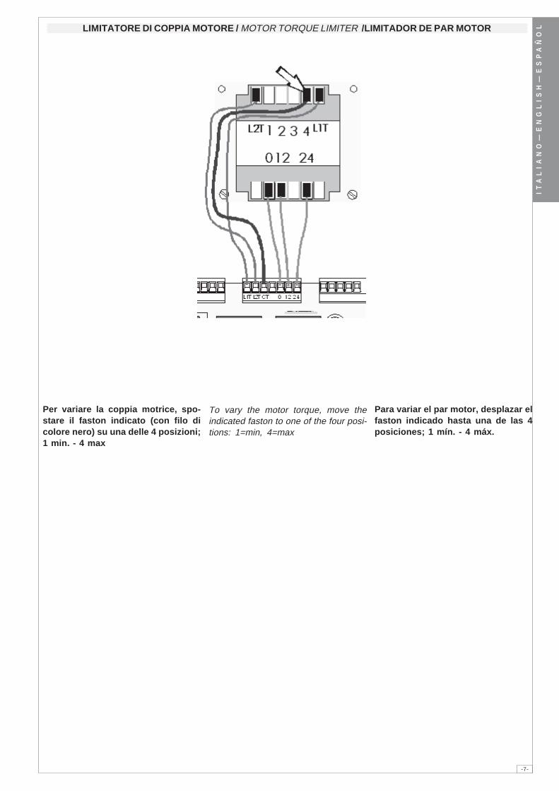
Per variare la coppia motrice, spo-stare il faston indicato (con filo dicolore nero) su una delle 4 posizioni;1 min. - 4 max
To vary the motor torque, move theindicated faston to one of the four posi-tions: 1=min, 4=max
Para variar el par motor, desplazar elfaston indicado hasta una de las 4posiciones; 1 mín. - 4 máx.
LIMITATORE DI COPPIA MOTORE / MOTOR TORQUE LIMITER /LIMITADOR DE PAR MOTOR
-8-
IT
AL
IA
NO
—E
NG
LI
SH
—E
SP
AÑ
OL
�� �� � � � ���� �� � �� � �� �� �� � �� ��� �
� ��
� ��
21 3 4 5 6 7 8 9 10
ON
L 1L 1L 1L 1L 1L 2L 2L 2L 2L 2
UUUUUWWWWWVVVVV
WWWWWE 1E 1E 1E 1E 1
1 1 1 1 1 2 2 2 2 2
22222 3P 3P 3P 3P 3P
1 01 01 01 01 01 11 11 11 11 1
2 2 2 2 2 7 7 7 7 7
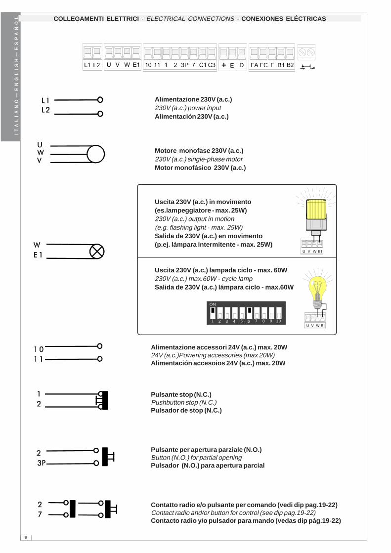
Alimentazione 230V (a.c.)230V (a.c.) power inputAlimentación 230V (a.c.)
Motore monofase 230V (a.c.)230V (a.c.) single-phase motorMotor monofásico 230V (a.c.)
Uscita 230V (a.c.) in movimento(es.lampeggiatore - max. 25W)230V (a.c.) output in motion(e.g. flashing light - max. 25W)Salida de 230V (a.c.) en movimento(p.ej. lámpara intermitente - max. 25W)
Uscita 230V (a.c.) lampada ciclo - max. 60W230V (a.c.) max.60W - cycle lampSalida de 230V (a.c.) lámpara ciclo - max.60W
COLLEGAMENTI ELETTRICI - ELECTRICAL CONNECTIONS - CONEXIONES ELÉCTRICAS
Alimentazione accessori 24V (a.c.) max. 20W24V (a.c.)Powering accessories (max 20W)Alimentación accesoios 24V (a.c.) max. 20W
Pulsante stop (N.C.)Pushbutton stop (N.C.)Pulsador de stop (N.C.)
Pulsante per apertura parziale (N.O.)Button (N.O.) for partial openingPulsador (N.O.) para apertura parcial
Contatto radio e/o pulsante per comando (vedi dip pag.19-22)Contact radio and/or button for control (see dip pag.19-22)Contacto radio y/o pulsador para mando (vedas dip pág.19-22)
-9-
IT
AL
IA
NO
—E
NG
LI
SH
—E
SP
AÑ
OL
1 11 11 11 11 1F CF CF CF CF C
1 11 11 11 11 1F AF AF AF AF A
22222C 1C 1C 1C 1C 1
FFFFFF AF AF AF AF A
FFFFFF CF CF CF CF C
22222C 3C 3C 3C 3C 3
B 1B 1B 1B 1B 1B 2B 2B 2B 2B 2
Lampada spia (24V-3W max.) "cancello aperto"(24V-3W max.) "gate-opened" signal lampLámpara indicadora (24V-3W max.) "puerta abierta"
Lampada spia (24V-3W max.) "cancello chiuso"(24V-3W max.) "gate-closed" signal lampLámpara indicadora (24V-3W max.) "puerta cierre"
Contatto (N.C.) di «riapertura durante la chiusura»Contact (N.C.) for «re-opening during the closing»Contacto (N.C.) para la «apertura en la fase de cierre»
Contatto (N.C.) di «stop parziale»Contact (N.C.) for «partial stop»Contacto (N.C.) para la «parada parcial»
Uscita contatto (N.O.) Portata contatto: 5A - 24V d.c.Contact output (N.O.) Resistive load: 5A - 24V d.c.Salida contacto (N.O.) Carga resistiva: 5A - 24V d.c.
Collegamento finecorsa apreConnection limit switch opensConexión fin de carrera apertura
Collegamento finecorsa chiudeConnection limit switch closesConexión fin de carrera cierre
Collegamento antennaAntenna connectionConexión antena
-10-
IT
AL
IA
NO
—E
NG
LI
SH
—E
SP
AÑ
OL
ONONONONONOFFOFFOFFOFFOFF
�� � � � � � � � ��
��
SELEZIONI FUNZIONI - SELECTION OF FUNCTIONS - SELECCIÓN DE LAS FUNCIONES
DIP-SWITCH 10 VIE / 10-WAY DIP-SWITCH / DIP-SWITCH 10 VÍAS
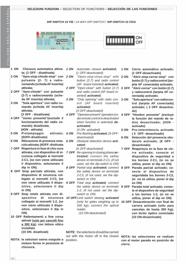
1 ON Cierre automático activado;(1 OFF-desactivado)
2 ON "Abrir-stop-cerrar-stop" conbotón (2-7) y radiocontrol (tar-jeta AF conectada) activado;
2 OFF "Abrir-cerrar" con botón (2-7)y radiocontrol (tarjeta AF co-nectada) activado;
3 ON "Solo apertura" con radiocon-trol (tarjeta AF conectada)activado; ( 3 OFF desactiva-do)
4 OFF "Hombre presente" (escluyela función del mando de ra-dio) desactivado; (4ON -activado)
5 ON Pre-intermitencia activado( 5 OFF- desactivado)
6 ON Detección del presencia obs-táculo activado; (6 OFF -desactivado)
7 OFF Reapertura en la fase de cie-rre activado; conecte eldispositivo de seguridad alos bornes 2-C1, (si no seutiliza, poner el dip en ON)
8 OFF Parada parcial activado; co-necte el dispositivo deseguridada los bornes 2-C3,(si no se utiliza, poner el dipen ON)
9 OFF Parada total activado; conec-te el dispositivo de seguridada los bornes 1-2, (si no seutiliza, poner el dip en ON)
10 OFF Desaceleración con final decarrera activado (sólo paracancelas de hasta 300 Kg);con lector óptico conectado(10 ON-desactivado)
NOTA: las selecciones se realizancon el motor parado en posición decierre.
1 ON Automatic closure activated; (1 OFF-deactivated)2 ON "Open-stop-close-stop" with
button (2-7) and radio control(AF board inserted) activated;
2 OFF "Open-close" with button (2-7)and radio control (AF board in-serted) activated;
3 ON "Only opening" with radio con-trol (AF board inserted)activated;
(3 OFF-deactivated)4 OFF "Operator present" operation (ra-
dio remote control is deactivatedwhen function is selected) de-activated;
(4 ON -activated)5 ON Pre-flashing activated; (5 OFF-
deactivated)6 ON Obstacle detection device acti-
vated; (6 OFF-deactivated)7 OFF Re-opening in closing phase ac-
tivated; connect the safetydevice on terminals 2-C1, (if notused, set the dip-switch to ON)
8 OFF Partial stop activated; connectthe safety device on terminals2-C3, (if not used, set the dip-switch to ON)
9 OFF Total stop activated; connectthe safety device on terminals1-2, (if not used, set the dip-switch to ON)
10 OFFLimit switch slowing activated(only for gates weighing up to300 kg); connect the opticalreader.
(10 ON-deactivated)
NOTE: the selections should be carriedout with the motor off in the closedposition.
1 ON Chiusura automatica attiva-ta; (1 OFF - disattivata)
2 ON "Apre-stop-chiude-stop" conpulsante (2- 7) e radio-comando (scheda AF inserita)attivata;
2 OFF "Apre-chiude" con pulsante(2-7) e radiocomando (sche-da AF inserita) attivata;
3 ON "Sola apertura" con radio co-mando (scheda AF inserita)attivata;
(3 OFF - disattivata)4 OFF "Uomo presente"(esclude il
funzionamento del radio co-mando) disattivata;
(4ON - attivata)5 ON Prelampeggio attivato;
(5OFF-disattivato)6 ON Rilevazione di presenza osta-
colo attivata; (6OFF- disttivata7 OFF Riapertura in fase di chiu sura
attivata; con dispositivo di si-curezza collegato ai morsetti2-C1, (se non viene utilizzatoil dispositivo, selezionare ildip in ON).
8 OFF Stop parziale attivata; condispositivo di sicurezza col-legato ai morsetti 2-C3, (senon viene utilizzato il dispo-sitivo, selezionare il dipin ON)
9 OFF Stop totale attivata con di-spositivo di sicurezzacollegato ai morsetti 1-2, (senon viene utilizzato il dispo-sitivo, selezionare il dip inON)
10 OFF Rallentamenti a fine corsaattivati (solo per cancelli finoa 300 Kg); con lettore otticoinstallato(10 ON- disattivati)
NOTA: le selezioni vanno eseguite amotore fermo in posizione dichiusura.
-11-
IT
AL
IA
NO
—E
NG
LI
SH
—E
SP
AÑ
OL
� � � � � � � �� � � � � �
������������ ���
���������������
����������� ���
������ �������
�������������� ���
ONONONONONOFFOFFOFFOFFOFF
�� ��
DIP-SWITCH 4 VIE / 4-WAY DIP-SWITCH / DIP-SWITCH 4 VÍAS
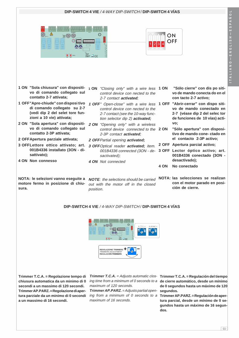
1 ON "Closing only" with a wire lesscontrol device con nected to the2-7 contact activated;
1 OFF" Open-close" with a wire lesscontrol device con nected to the2-7 contact (see the 10-way func-tion selector dip 2) activated;
2 ON "Opening only" with a wirelesscontrol device connected to the2-3P contact activated;
2 OFFPartial opening activated;
3 OFFOptical reader activated; item.001B4336 connected (3ON - de-sactivated);
4 ON Not connected
NOTE: the selections should be carriedout with the motor off in the closedposition.
1 ON "Sólo cierre" con dis po siti-vo de mando conecta do en elcon tacto 2-7 activo;
1 OFF "Abrir-cerrar" con dispo siti-vo de mando conectado en2-7 (véase dip 2 del selec torde funciones de 10 vías) acti-vo;
2 ON "Sólo apertura" con disposi-tivo de mando cone- ctado enel contacto 2-3P activo;
2 OFF Apertura parcial activo;
3 OFF Lector óptico activo; art.001B4336 conectado (3ON -desactivado);
4 ON No conectado
NOTA: las selecciones se realizancon el motor parado en posi-ción de cierre.
1 ON "Sola chiusura" con dispositi-vo di comando collegato sulcontatto 2-7 attivata;
1 OFF"Apre-chiude" con disposi tivodi comando collegato su 2-7(vedi dip 2 del selet tore fun-zioni a 10 vie) attivata;
2 ON "Sola apertura" con dispositi-vo di comando collegato sulcontatto 2-3P attivata;
2 OFFApertura parziale attivata;
3 OFFLettore ottico attivato; art.001B4336 installato (3ON - di-sattivato);
4 ON Non connesso
NOTA: le selezioni vanno eseguite amotore fermo in posizione di chiu-sura.
Trimmer T.C.A. = Regulación del tiempode cierre automático, desde un mínimode 0 segundos hasta un máximo de 120segundos.Trimmer AP.PARZ. = Regulación de aper-tura parcial, desde un mínimo de 0 se-gundos hasta un máximo de 16 segun-dos.
Trimmer T.C.A. = Regolazione tempo dichiusura automatica da un minimo di 0secondi a un massimo di 120 secondi.Trimmer AP.PARZ. = Regolazione di aper-tura parziale da un minimo di 0 secondia un massimo di 16 secondi.
Trimmer T.C.A. = Adjusts automatic clos-ing time from a minimum of 0 seconds to amaximum of 120 seconds.Trimmer AP.PARZ. = Adjusts partial open-ing from a minimum of 0 seconds to amaximum of 16 seconds.
DIP-SWITCH 4 VIE / 4-WAY DIP-SWITCH / DIP-SWITCH 4 VÍAS
REGOLAZIONE TRIMMERSTRIMMERS ADJUSTMENTREGULACIÓN TRIMMERS
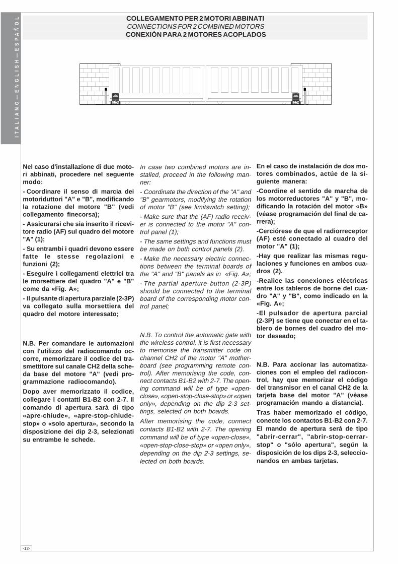
-12-
IT
AL
IA
NO
—E
NG
LI
SH
—E
SP
AÑ
OL COLLEGAMENTO PER 2 MOTORI ABBINATI
CONNECTIONS FOR 2 COMBINED MOTORS CONEXIÓN PARA 2 MOTORES ACOPLADOS
Nel caso d'installazione di due moto-ri abbinati, procedere nel seguentemodo:
- Coordinare il senso di marcia deimotoriduttori "A" e "B", modificandola rotazione del motore "B" (vedicollegamento finecorsa);
- Assicurarsi che sia inserito il ricevi-tore radio (AF) sul quadro del motore"A" (1);
- Su entrambi i quadri devono esserefatte le stesse regolazioni efunzioni (2);
- Eseguire i collegamenti elettrici trale morsettiere del quadro "A" e "B"come da «Fig. A»;
- Il pulsante di apertura parziale (2-3P)va collegato sulla morsettiera delquadro del motore interessato;
N.B. Per comandare le automazionicon l'utilizzo del radiocomando oc-corre, memorizzare il codice del tra-smettitore sul canale CH2 della sche-da base del motore "A" (vedi pro-grammazione radiocomando).
Dopo aver memorizzato il codice,collegare i contatti B1-B2 con 2-7. Ilcomando di apertura sarà di tipo«apre-chiude», «apre-stop-chiude-stop» o «solo apertura», secondo ladisposizione dei dip 2-3, selezionatisu entrambe le schede.
In case two combined motors are in-stalled, proceed in the following man-ner:
- Coordinate the direction of the "A" and"B" gearmotors, modifying the rotationof motor "B" (see limitswitch setting);
- Make sure that the (AF) radio receiv-er is connected to the motor "A" con-trol panel (1);
- The same settings and functions mustbe made on both control panels (2).
- Make the necessary electric connec-tions between the terminal boards ofthe "A" and "B" panels as in «Fig. A»;
- The partial aperture button (2-3P)should be connected to the terminalboard of the corresponding motor con-trol panel;
N.B. To control the automatic gate withthe wireless control, it is first necessaryto memorise the transmitter code onchannel CH2 of the motor "A" mother-board (see programming remote con-trol). After memorising the code, con-nect contacts B1-B2 with 2-7. The open-ing command will be of type «open-close», «open-stop-close-stop» or «openonly», depending on the dip 2-3 set-tings, selected on both boards.
After memorising the code, connectcontacts B1-B2 with 2-7. The openingcommand will be of type «open-close»,«open-stop-close-stop» or «open only»,depending on the dip 2-3 settings, se-lected on both boards.
En el caso de instalación de dos mo-tores combinados, actúe de la si-guiente manera:
-Coordine el sentido de marcha delos motorreductores "A" y "B", mo-dificando la rotación del motor «B»(véase programación del final de ca-rrera);
-Cerciórese de que el radiorreceptor(AF) esté conectado al cuadro delmotor "A" (1);
-Hay que realizar las mismas regu-laciones y funciones en ambos cua-dros (2).
-Realice las conexiones eléctricasentre los tableros de borne del cua-dro "A" y "B", como indicado en la«Fig. A»;
-El pulsador de apertura parcial(2-3P) se tiene que conectar en el ta-blero de bornes del cuadro del mo-tor deseado;
N.B. Para accionar las automatiza-ciones con el empleo del radiocon-trol, hay que memorizar el códigodel transmisor en el canal CH2 de latarjeta base del motor "A" (véaseprogramación mando a distancia).
Tras haber memorizado el código,conecte los contactos B1-B2 con 2-7.El mando de apertura será de tipo"abrir-cerrar", "abrir-stop-cerrar-stop" o "sólo apertura", según ladisposición de los dips 2-3, seleccio-nandos en ambas tarjetas.
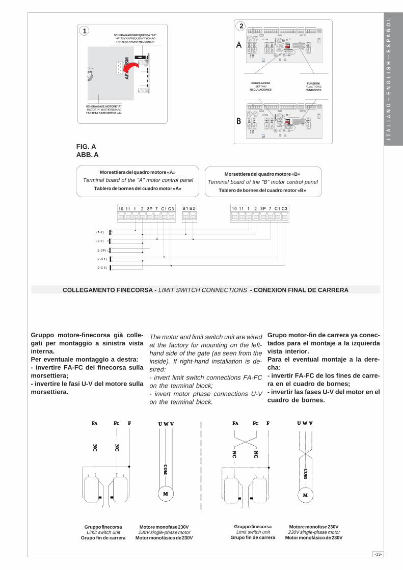
-13-
IT
AL
IA
NO
—E
NG
LI
SH
—E
SP
AÑ
OL
FIG. AABB. A
�� �� � � � ��� �� �� �� �� � � � ��� ����
�����
�����
���� �
���� ��
���� ��
FUS.
AC
CESS
ORI
1A
�� ��
FUS.
AC
CESS
ORI
1A
�� ��
AAAAA
BBBBB
2
� � � �
��������
1
CO
MC
OM
CO
MC
OM
CO
M
U W VU W VU W VU W VU W V
NC
NC
NC
NC
NC
NC
NC
NC
NC
NC
NC
NC
NC
NC
NC
NC
NC
NC
NC
NC
U W VU W VU W VU W VU W V
CO
MC
OM
CO
MC
OM
CO
M
FFFFFFFFFFCCCCCFFFFFAAAAA FFFFFCCCCCFFFFFAAAAA FFFFF
MMMMMMMMMM
Morsettiera del quadro motore «B»
Terminal board of the "B" motor control panel
Tablero de bornes del cuadro motor «B»
Morsettiera del quadro motore «A»
Terminal board of the "A" motor control panel
Tablero de bornes del cuadro motor «A»
FUNZIONIFUNCTIONSFUNCIONES
REGOLAZIONISETTING
REGULACIONES
SCHEDA RADIOFREQUENZA "AF""AF" RADIO FREQUENCY BOARDTARJETA RADIOFRECUENCIA
SCHEDA BASE MOTORE "A"MOTOR "A" MOTHERBOARDTARJETA BASE MOTOR «A»
COLLEGAMENTO FINECORSA - LIMIT SWITCH CONNECTIONS - CONEXION FINAL DE CARRERA
Gruppo motore-finecorsa già colle-gati per montaggio a sinistra vistainterna.Per eventuale montaggio a destra:- invertire FA-FC dei finecorsa sullamorsettiera;- invertire le fasi U-V del motore sullamorsettiera.
The motor and limit switch unit are wiredat the factory for mounting on the left-hand side of the gate (as seen from theinside). If right-hand installation is de-sired:- invert limit switch connections FA-FCon the terminal block;- invert motor phase connections U-Von the terminal block.
Grupo motor-fin de carrera ya conec-tados para el montaje a la izquierdavista interior.Para el eventual montaje a la dere-cha:- invertir FA-FC de los fines de carre-ra en el cuadro de bornes;- invertir las fases U-V del motor en elcuadro de bornes.
Gruppo finecorsaLimit switch unit
Grupo fin de carrera
Motore monofase 230V230V single-phase motor
Motor monofásico de 230V
Motore monofase 230V230V single-phase motor
Motor monofásico de 230V
Gruppo finecorsaLimit switch unit
Grupo fin de carrera
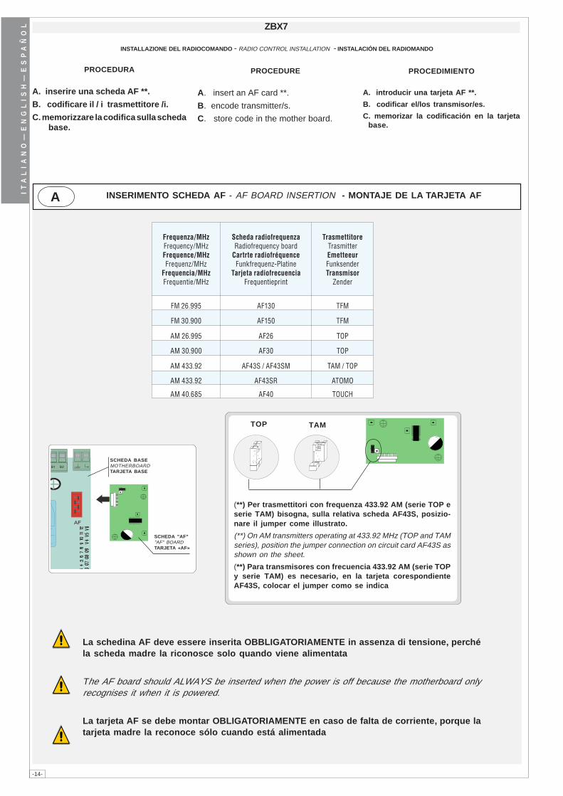
-14-
IT
AL
IA
NO
—E
NG
LI
SH
—E
SP
AÑ
OL ZBX7
TOP TAM
A
Frequenza/MHzFrequency/MHzFrequence/MHzFrequenz/MHz
Frequencia/MHzFrequentie/MHz
Scheda radiofrequenzaRadiofrequency board
Cartrte radiofréquenceFunkfrequenz-Platine
Tarjeta radiofrecuenciaFrequentieprint
TrasmettitoreTrasmitterEmetteeurFunksenderTransmisor
Zender
FM 26.995 AF130 TFM
FM 30.900 AF150 TFM
AM 26.995 AF26 TOP
AM 30.900 AF30 TOP
AM 433.92 AF43S / AF43SM TAM / TOP
AM 433.92 AF43SR ATOMO
AM 40.685 AF40 TOUCH
INSTALLAZIONE DEL RADIOCOMANDO - RADIO CONTROL INSTALLATION - INSTALACIÓN DEL RADIOMANDO
PROCEDURA
A. inserire una scheda AF **.
B. codificare il / i trasmettitore /i.
C. memorizzare la codifica sulla schedabase.
PROCEDURE
A. insert an AF card **.
B. encode transmitter/s.
C. store code in the mother board.
PROCEDIMIENTO
A. introducir una tarjeta AF **.
B. codificar el/los transmisor/es.
C. memorizar la codificación en la tarjetabase.
(**) Per trasmettitori con frequenza 433.92 AM (serie TOP eserie TAM) bisogna, sulla relativa scheda AF43S, posizio-nare il jumper come illustrato.
(**) On AM transmitters operating at 433.92 MHz (TOP and TAMseries), position the jumper connection on circuit card AF43S asshown on the sheet.
(**) Para transmisores con frecuencia 433.92 AM (serie TOPy serie TAM) es necesario, en la tarjeta corespondienteAF43S, colocar el jumper como se indica
INSERIMENTO SCHEDA AF - AF BOARD INSERTION - MONTAJE DE LA TARJETA AF
SCHEDA BASEMOTHERBOARDTARJETA BASE
SCHEDA "AF""AF" BOARDTARJETA «AF»
La schedina AF deve essere inserita OBBLIGATORIAMENTE in assenza di tensione, perchéla scheda madre la riconosce solo quando viene alimentata
The AF board should ALWAYS be inserted when the power is off because the motherboard onlyrecognises it when it is powered.
La tarjeta AF se debe montar OBLIGATORIAMENTE en caso de falta de corriente, porque latarjeta madre la reconoce sólo cuando está alimentada
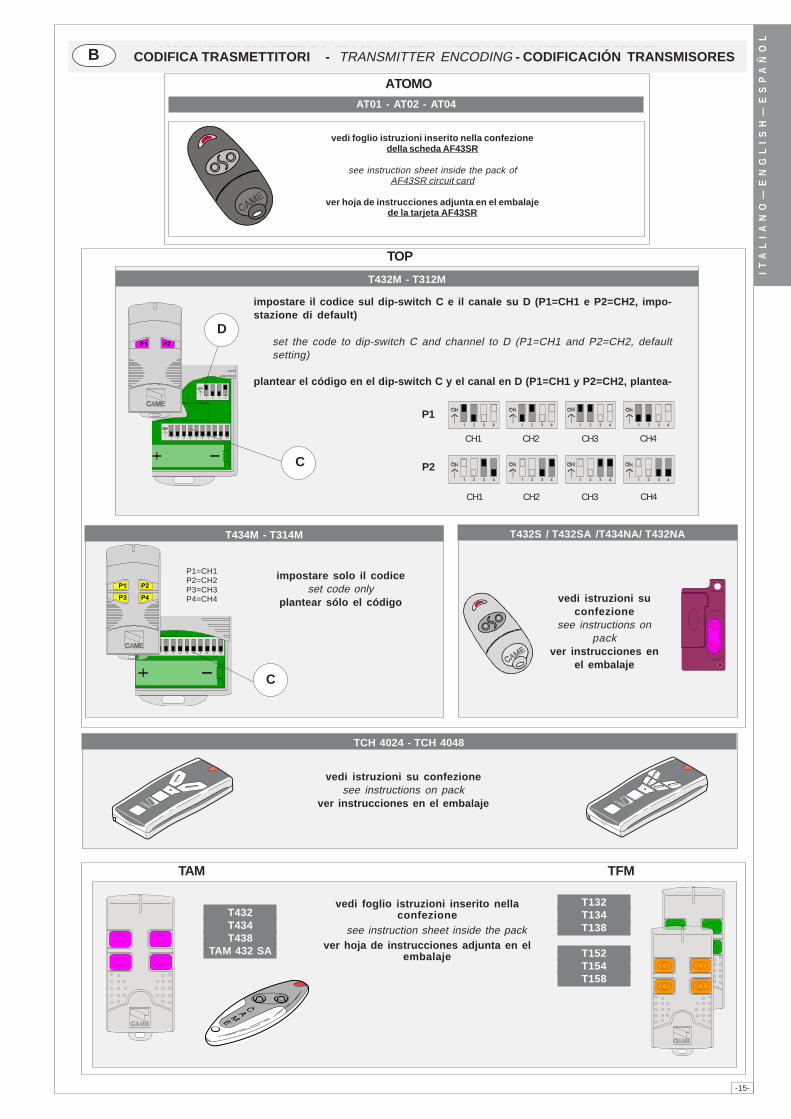
-15-
IT
AL
IA
NO
—E
NG
LI
SH
—E
SP
AÑ
OL
AT01 - AT02 - AT04
ATOMO
TAM
T132T134T138
T152T154T158
T432T434T438
TAM 432 SA
TFM
TOP
T432M - T312M
� � � � � � � � � ��
� � � �
C
D�� ��
P2
CH1 CH2 CH3 CH4
P1
CH1 CH2 CH3 CH4
� � � � � � � � � � � �� � � �
� � � � � � � � � � � � � � � �
T434M - T314M
P1=CH1P2=CH2P3=CH3P4=CH4
� � � � � � � � � ��
C
�� ��
�� ��
T432S / T432SA /T434NA/ T432NA
CODIFICATION DES EMETTEURS - PROGRAMMATIE VAN DE ZENDERS - CODIERUNG DER SENDERB
TCH 4024 - TCH 4048
vedi foglio istruzioni inserito nellaconfezione
see instruction sheet inside the packver hoja de instrucciones adjunta en el
embalaje
impostare solo il codiceset code only
plantear sólo el código vedi istruzioni suconfezione
see instructions onpack
ver instrucciones enel embalaje
impostare il codice sul dip-switch C e il canale su D (P1=CH1 e P2=CH2, impo-stazione di default)
set the code to dip-switch C and channel to D (P1=CH1 and P2=CH2, defaultsetting)
plantear el código en el dip-switch C y el canal en D (P1=CH1 y P2=CH2, plantea-
vedi foglio istruzioni inserito nella confezionedella scheda AF43SR
see instruction sheet inside the pack ofAF43SR circuit card
ver hoja de instrucciones adjunta en el embalajede la tarjeta AF43SR
CODIFICA TRASMETTITORI - TRANSMITTER ENCODING - CODIFICACIÓN TRANSMISORES
vedi istruzioni su confezionesee instructions on pack
ver instrucciones en el embalaje
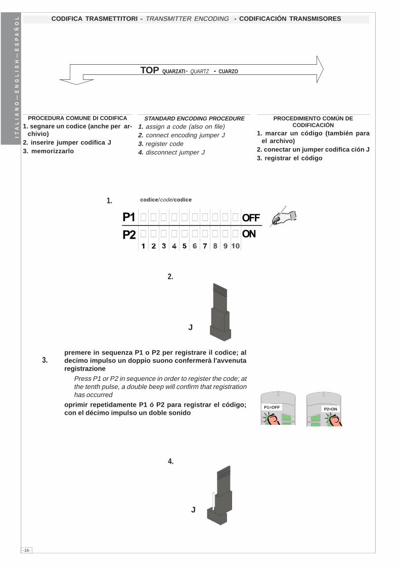
-16-
IT
AL
IA
NO
—E
NG
LI
SH
—E
SP
AÑ
OL
2.
J
P1=OFF P2=ON
3.
4.
J
��
���
��
codice/code/codice1.
CODIFICA TRASMETTITORI - TRANSMITTER ENCODING - CODIFICACIÓN TRANSMISORES
PROCEDURA COMUNE DI CODIFICA1. segnare un codice (anche per ar-
chivio)2. inserire jumper codifica J3. memorizzarlo
STANDARD ENCODING PROCEDURE1. assign a code (also on file)2. connect encoding jumper J3. register code4. disconnect jumper J
PROCEDIMIENTO COMÚN DECODIFICACIÓN
1. marcar un código (también parael archivo)
2. conectar un jumper codifica ción J3. registrar el código
TOP QUARZATI- QUARTZ - CUARZO
premere in sequenza P1 o P2 per registrare il codice; aldecimo impulso un doppio suono confermerà l'avvenutaregistrazione
Press P1 or P2 in sequence in order to register the code; atthe tenth pulse, a double beep will confirm that registrationhas occurred
oprimir repetidamente P1 ó P2 para registrar el código;con el décimo impulso un doble sonido
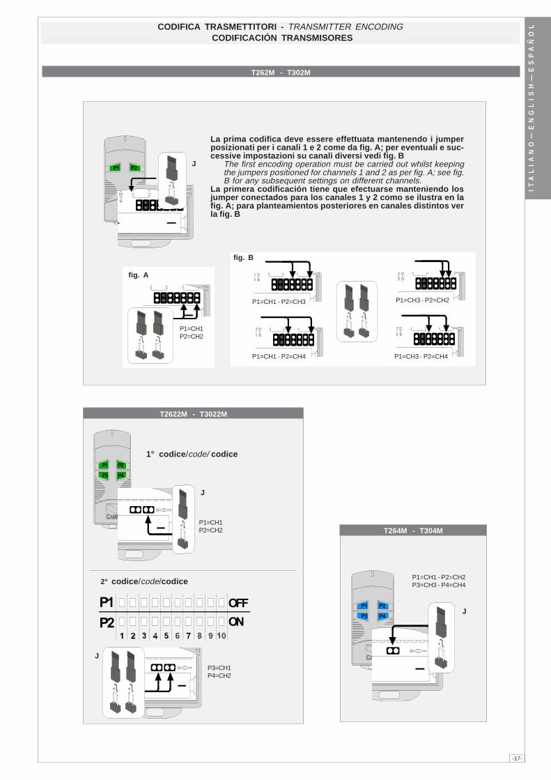
-17-
IT
AL
IA
NO
—E
NG
LI
SH
—E
SP
AÑ
OL
T262M - T302M
fig. B
P1=CH1 - P2=CH4
P1=CH1 - P2=CH3 P1=CH3 - P2=CH2
P1=CH3 - P2=CH4
P1=CH1P2=CH2
fig. A
T2622M - T3022M
2° codice/code/codice
��
���
��
P3=CH1P4=CH2
J
1° codice/code/ codice�� ��
�� ��
P1=CH1P2=CH2
J
�� ��
�� ��
P1=CH1 - P2=CH2P3=CH3 - P4=CH4
J
J�� ��
T264M - T304M
CODIFICA TRASMETTITORI - TRANSMITTER ENCODING CODIFICACIÓN TRANSMISORES
La prima codifica deve essere effettuata mantenendo i jumperposizionati per i canali 1 e 2 come da fig. A; per eventuali e suc-cessive impostazioni su canali diversi vedi fig. B
The first encoding operation must be carried out whilst keepingthe jumpers positioned for channels 1 and 2 as per fig. A; see fig.B for any subsequent settings on different channels.
La primera codificación tiene que efectuarse manteniendo losjumper conectados para los canales 1 y 2 como se ilustra en lafig. A; para planteamientos posteriores en canales distintos verla fig. B
-18-
IT
AL
IA
NO
—E
NG
LI
SH
—E
SP
AÑ
OL C MEMORIZZAZIONE CODICE - CODE STORAGE - MEMORIZACIÓN CÓDIGO
a) tenere premuto il tasto "CH1" sullascheda base, il led di segnalazionelampeggia;
b) con un tasto del trasmettitore s'in-via il codice, il led rimarrà acceso asegnalare l'avvenuta memorizzazio-ne (fig.1).
Eseguire la stessa procedura con iltasto "CH2" associandolo con un al-tro tasto del trasmettitore (fig.2).
CH1 = Canale per comandi diretti aduna funzione della centralina del mo-toriduttore (comando "solo apre" /"apre-chiude-inversione" oppure"apre-stop-chiude-stop", a secondadella selezione effetuata sui dip-switch 2 e 3).
CH2 = Canale per comandi diretti adun dispositivo accessorio, collegatosu B1-B2.
N.B.: se in seguito si vuol cambiarecodice, ripetere la sequenza descrit-ta.
a) press down and hold the "CH1" keyon the base board (the signal LED willflash);
b) send the code with a button on thetransmitter, the LED will remain lit toindicate that the data has been savedplace (fig.1).
Perform the same procedure with the"CH2" key, associating it with anothertransmitter key (fig.2).
CH1 = Channel for direct control of onefunction performed by the control uniton the gear motor ("open only" / "open-close-reverse" or "open-stop-close-stop", depending on the position of dipswitches 2 and 3).
CH2 = Channel for direct control of anaccessory connected across B1-B2.
N.B. If you wish to change the code onyour transmitters in the future, simplyrepeat the procedure described above.
a) mantenga apretada la tecla "CH1"en la tarjeta base (el indicador lumi-noso de señal parpadea);
b) con la tecla del transmisor se en-vía el código, el indicador luminosopermanece encendido para indicarque la memorización se ha llevado acabo (fig.1).
Efectuar el mismo procedimiento conla tecla "CH2" asociándola a otratecla del transmisor (fig.2).
CH1 = Canal para mando directo auna función de la central del moto-rreductor (mando "solo abre" / "abre-cierra-inversión" o "abre-stop-cierra-stop", según la selección efectuadaen los dip-switch 2 y 3).
CH2 = Canal para un mando directo aun dispositivo accesorio conectadoen B1-B2.
Nota: si posteriormente se quisieracambiar el código de los propiostransmisores, sólo hay que repetir lasecuencia descrita.
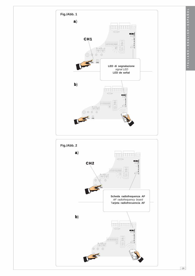
-19-
IT
AL
IA
NO
—E
NG
LI
SH
—E
SP
AÑ
OL
CH1 CH2
CH1 CH2
aaaaa)
bbbbb)
Fig./Abb. 1
aaaaa)
CH2CH2CH2CH2CH2
bbbbb)
Fig./Abb. 2
CH1 CH2
CH1CH1CH1CH1CH1
CH1 CH2
LED di segnalazione signal LED
LED de señal
Scheda radiofrequenza AFAF radiofrequency board
Tarjeta radiofrecuencia AF
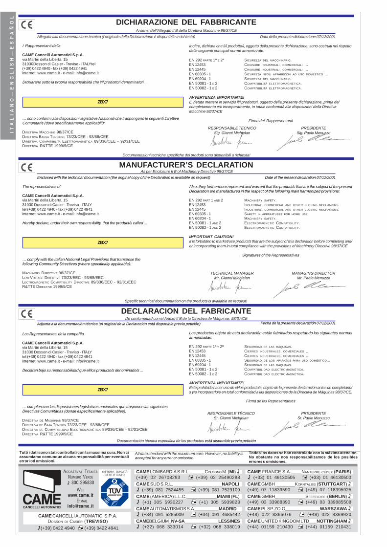
CAME LOMBARDIA S.R.L.______COLOGNO M. (MI) (+39) 02 26708293 (+39) 02 25490288
CAME SUD S.R.L. ___________________NAPOLI (+39) 081 7524455 (+39) 081 7529109
CAME (AMERICA) L.L.C.____________MIAMI (FL) (+1) 305 5930227 (+1) 305 5939823
CAME AUTOMATISMOS S.A__________MADRID (+34) 091 5285009 (+34) 091 4685442
CAMEBELGIUM_NV-SA______________LESSINES (+32) 068 333014 (+32) 068 338019
CAME FRANCE S.A.____NANTERRE CEDEX (PARIS) (+33) 01 46130505 (+33) 01 46130500
CAME GMBH________KORNTAL BEI (STUTTGART) (+49) 07 11839590 (+49) 07 118395925
CAME GMBH____________SEEFELD BEI (BERLIN) (+49) 03 33988390 (+49) 03 339885508
CAME PL SP.ZO.O______________WARSZAWA (+48) 022 8365076 (+48) 022 8369920
CAME UNITED KINGDOM LTD___NOTTINGHAM (+44) 01159 210430 (+44) 01159 210431
CAME CANCELLI AUTOMATICI S.P.A.DOSSON DI CASIER (TREVISO)
(+39) 0422 4940 (+39) 0422 4941
SISTEMA QUALITÀCERTIFICATO
ASSISTENZA TECNICA
NUMERO VERDE
800 295830
WEB
www.came.it E-MAIL
Tutti i dati sono stati controllati con la massima cura. Non ciassumiamo comunque alcuna responsabilità per eventualierrori od omissioni.
All data checked with the maximum care. However, no liability isaccepted for any error or omission.
Todos los datos se han controlado con la máxima atención.No obstante no nos responsabilizamos de los posibleserrores u omisiones.
IT
AL
IA
NO
—E
NG
LI
SH
—E
SP
AÑ
OL
DICHIARAZIONE DEL FABBRICANTEAi sensi dell’Allegato II B della Direttiva Macchine 98/37/CE
I Rappresentanti della
CAME Cancelli Automatici S.p.A.via Martiri della Libertà, 1531030Dosson di Casier - Treviso - ITALYtel(+39) 0422 4940 - fax (+39) 0422 4941internet: www.came.it - e-mail: [email protected]
Dichiarano sotto la propria responsabilità che i/il prodotto/i denominato/i ...
… sono conformi alle disposizioni legislative Nazionali che traspongono le seguenti DirettiveComunitarie (dove specificatamente applicabili):
DIRETTIVA MACCHINE 98/37/CEDIRETTIVA BASSA TENSIONE 73/23/CEE - 93/68/CEEDIRETTIVA COMPATIBILITÀ ELETTROMAGNETICA 89/336/CEE - 92/31/CEEDIRETTIVA R&TTE 1999/5/CE
Inoltre, dichiara che il/i prodotto/i, oggetto della presente dichiarazione, sono costruiti nel rispettodelle seguenti principali norme armonizzate:
EN 292 PARTE 1ª E 2ª SICUREZZA DEL MACCHINARIO.EN 12453 CHIUSURE INDUSTRIALI, COMMERCIALI …EN 12445 CHIUSURE INDUSTRIALI, COMMERCIALI …EN 60335 - 1 SICUREZZA NEGLI APPARECCHI AD USO DOMESTICO ...EN 60204 - 1 SICUREZZA DEL MACCHINARIO.EN 50081 - 1 E 2 COMPATIBILITÀ ELETTROMAGNETICA.EN 50082 - 1 E 2 COMPATIBILITÀ ELETTROMAGNETICA.
AVVERTENZA IMPORTANTE!È vietato mettere in servizio il/i prodotto/i, oggetto della presente dichiarazione, prima delcompletamento e/o incorporamento, in totale conformità alle disposizioni della DirettivaMacchine 98/37/CE
Firma dei Rappresentanti
Documentazioni tecniche specifiche dei prodotti sono disponibili a richiesta!
Data della presente dichiarazione 07/12/2001
Also, they furthermore represent and warrant that the product/s that are the subject of the presentDeclaration are manufactured in the respect of the following main harmonized provisions:
EN 292 PART 1 AND 2 MACHINERY SAFETY.EN 12453 INDUSTRIAL, COMMERCIAL AND OTHER CLOSING MECHANISMS.EN 12445 INDUSTRIAL, COMMERCIAL AND OTHER CLOSING MECHANISMS.EN 60335 - 1 SAFETY IN APPARATUSES FOR HOME USE.EN 60204 - 1 MACHINERY SAFETY.EN 50081 - 1 AND 2 ELECTROMAGNETIC COMPATIBILITY.EN 50082 - 1 AND 2 ELECTROMAGNETIC COMPATIBILITY.
IMPORTANT CAUTION!It is forbidden to market/use product/s that are the subject of this declaration before completing and/or incorporating them in total compliance with the provisions of Machinery Directive 98/37/CE
Signatures of the Representatives
Specific technical documentation on the products is available on request!
Date of the present declaration 07/12/2001
MANUFACTURER’S DECLARATION As per Enclosure II B of Machinery Directive 98/37/CE
The representatives of
CAME Cancelli Automatici S.p.A.via Martiri della Libertà, 1531030 Dosson di Casier - Treviso - ITALYtel (+39) 0422 4940 - fax (+39) 0422 4941internet: www.came.it - e-mail: [email protected]
Hereby declare, under their own respons ibility, that the product/s called ...
… comply with the Italian National Legal Provisions that transpose thefollowing Community Directives (where specifically applicable):
MACHINERY DIRECTIVE 98/37/CELOW VOLTAGE DIRECTIVE 73/23/EEC - 93/68/EECLECTROMAGNETIC COMPATIBILITY DIRECTIVE 89/336/EEC - 92/31/EECR&TTE DIRECTIVE 1999/5/CE
DECLARACION DEL FABRICANTEDe conformidad con el Anexo II B de la Directiva de Máquinas 98/37/CE
Fecha de la presente declaración 07/12/2001Adjunta a la documentación técnica (el original de la Declaración está disponible previa petición)
Los Representantes de la compañía
CAME Cancelli Automatici S.p.A.via Martiri della Libertà, 1531030 Dosson di Casier - Treviso - ITALYtel (+39) 0422 4940 - fax (+39) 0422 4941internet: www.came.it - e-mail: [email protected]
Declaran bajo su responsabilidad que el/los producto/s denominado/s ...
… cumplen con las disposiciones legislativas nacionales que trasponen las siguientesDirectivas Comunitarias (donde específicamente aplicables):
DIRECTIVA DE MÁQUINAS 98/37/CEDIRECTIVA DE BAJA TENSIÓN 73/23/CEE - 93/68/CEEDIRECTIVA DE COMPATIBILIDAD ELECTROMAGNÉTICA 89/336/CEE - 92/31/CEEDIRECTIVA R&TTE 1999/5/CE
Los productos objeto de esta declaración están fabricados respetando las siguientes normasarmonizadas:
EN 292 PARTE 1ª Y 2ª SEGURIDAD DE LAS MÁQUINAS.EN 12453 CIERRES INDUSTRIALES, COMERCIALES …EN 12445 CIERRES INDUSTRIALES, COMERCIALES …EN 60335 - 1 SEGURIDAD DE LOS APARATOS PARA USO DOMÉSTICO...EN 60204 - 1 SEGURIDAD DE LAS MÁQUINAS.EN 50081 - 1 E 2 COMPATIBILIDAD ELECTROMAGNÉTICA.EN 50082 - 1 E 2 COMPATIBILIDAD ELECTROMAGNÉTICA.
AVVERTENZA IMPORTANTE!Está prohibido hacer uso de el/los producto/s, objeto de la presente declaración antes de completarlo/s y/o incorporarlo/s en total conformidad a las disposiciones de la Directiva de Máquinas 98/37/CE.
Firma de los Representantes
Documentación técnica específica de los productos está disponible previa petición
Enclosed with the technical documentation (the original copy of the Declaration is available on request)
Allegata alla documentazione tecnica (l’originale della Dichiarazione è disponibile a richiesta)
RESPONSABILE TECNICOSig. Gianni Michielan
PRESIDENTESig. Paolo Menuzzo
TECHNICAL MANAGERMr. Gianni Michielan
MANAGING DIRECTORMr. Paolo Menuzzo
RESPONSABLE TÉCNICOSr. Gianni Michielan
PRESIDENTESr. Paolo Menuzzo
ZBX7
ZBX7
ZBX7