INDIAN SCHOOL WADI KABIR English Core (Code No.301) Examination Specifications.
Rev 1 08/02/2017
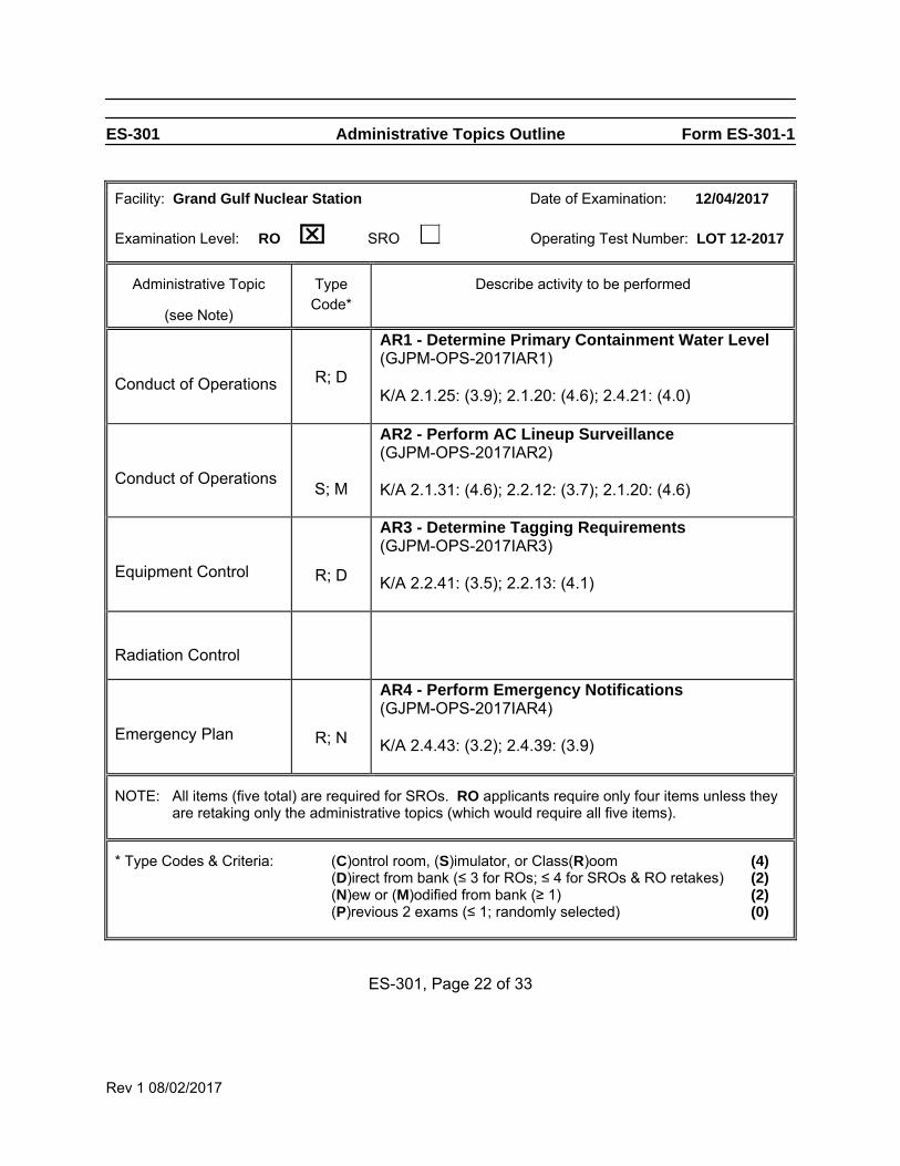
ES-301 Administrative Topics Outline Form ES-301-1
Facility: Grand Gulf Nuclear Station Date of Examination: 12/04/2017
Examination Level: RO SRO Operating Test Number: LOT 12-2017
Administrative Topic
(see Note)
Type Code*
Describe activity to be performed
Conduct of Operations
R; D
AR1 - Determine Primary Containment Water Level (GJPM-OPS-2017IAR1) K/A 2.1.25: (3.9); 2.1.20: (4.6); 2.4.21: (4.0)
Conduct of Operations
S; M
AR2 - Perform AC Lineup Surveillance (GJPM-OPS-2017IAR2) K/A 2.1.31: (4.6); 2.2.12: (3.7); 2.1.20: (4.6)
Equipment Control
R; D
AR3 - Determine Tagging Requirements (GJPM-OPS-2017IAR3) K/A 2.2.41: (3.5); 2.2.13: (4.1)
Radiation Control
Emergency Plan
R; N
AR4 - Perform Emergency Notifications (GJPM-OPS-2017IAR4) K/A 2.4.43: (3.2); 2.4.39: (3.9)
NOTE: All items (five total) are required for SROs. RO applicants require only four items unless they are retaking only the administrative topics (which would require all five items).
* Type Codes & Criteria: (C)ontrol room, (S)imulator, or Class(R)oom (4) (D)irect from bank (≤ 3 for ROs; ≤ 4 for SROs & RO retakes) (2) (N)ew or (M)odified from bank (≥ 1) (2) (P)revious 2 exams (≤ 1; randomly selected) (0)
ES-301, Page 22 of 33
Rev. 1 08/02/2017
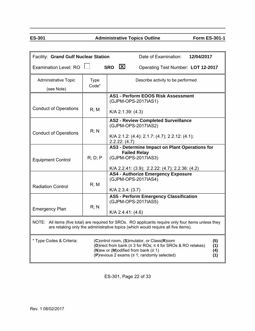
ES-301 Administrative Topics Outline Form ES-301-1
Facility: Grand Gulf Nuclear Station Date of Examination: 12/04/2017
Examination Level: RO SRO Operating Test Number: LOT 12-2017
Administrative Topic
(see Note)
Type Code*
Describe activity to be performed
Conduct of Operations
R; M
AS1 - Perform EOOS Risk Assessment (GJPM-OPS-2017IAS1) K/A 2.1.39: (4.3)
Conduct of Operations
R; N
AS2 - Review Completed Surveillance (GJPM-OPS-2017IAS2) K/A 2.1.2: (4.4); 2.1.7: (4.7); 2.2.12: (4.1); 2.2.22: (4.7)
Equipment Control
R; D; P
AS3 - Determine Impact on Plant Operations for Failed Relay
(GJPM-OPS-2017IAS3) K/A 2.2.41: (3.9); 2.2.22: (4.7); 2.2.36: (4.2)
Radiation Control
R; M
AS4 - Authorize Emergency Exposure (GJPM-OPS-2017IAS4) K/A 2.3.4: (3.7)
Emergency Plan
R; N
AS5 - Perform Emergency Classification (GJPM-OPS-2017IAS5) K/A 2.4.41: (4.6)
NOTE: All items (five total) are required for SROs. RO applicants require only four items unless they are retaking only the administrative topics (which would require all five items).
* Type Codes & Criteria: (C)ontrol room, (S)imulator, or Class(R)oom (5) (D)irect from bank (≤ 3 for ROs; ≤ 4 for SROs & RO retakes) (1) (N)ew or (M)odified from bank (≥ 1) (4) (P)revious 2 exams (≤ 1; randomly selected) (1)
ES-301, Page 22 of 33
Date of Examination: 12/04/2017
Operating Test Number: GGNS 12‐2017
Facility: Grand Gulf Nuclear Station
JPM Number: GJPM‐OPS‐2017IAR1
Rev. 01 11/06/2017 Page 1 of 11
2017I AR1
GGNS
2017I NRC Operating Test
Job Performance Measure
JPM Number: GJPM‐OPS‐2017IAR1 JPM Title: Determine Primary
Containment Water Level Facility Number: GJPM‐OPS‐AUDIT 2015AR2 (If Bank or Modified from Bank)
JPM Attributes:
New Modified Direct from bank
Time Critical Alternate Path Validation Time: 10 min
Prepared By: Michael Rasch 11/06/2017
Exam Developer Date
Ops Review: Robert Brinkman 11/06/2017
1st Validation by Ops Rep or Ops Validation Crew Date
Validated By: Benny White \ Chase Miller 11/06/2017
2nd Validation by Ops Validation Crew Date
Approved By: Ricky Liddell 11/06/2017
Project Lead or Exam Team Lead Date
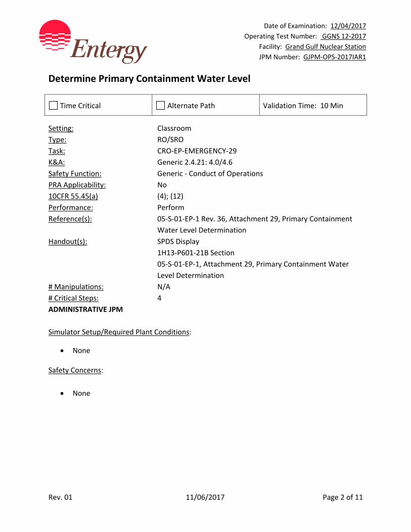
Date of Examination: 12/04/2017
Operating Test Number: GGNS 12‐2017
Facility: Grand Gulf Nuclear Station
JPM Number: GJPM‐OPS‐2017IAR1
Rev. 01 11/06/2017 Page 2 of 11
Determine Primary Containment Water Level
Time Critical Alternate Path Validation Time: 10 Min
Setting: Classroom
Type: RO/SRO
Task: CRO‐EP‐EMERGENCY‐29
K&A: Generic 2.4.21: 4.0/4.6
Safety Function: Generic ‐ Conduct of Operations
PRA Applicability: No
10CFR 55.45(a) (4); (12)
Performance: Perform
Reference(s): 05‐S‐01‐EP‐1 Rev. 36, Attachment 29, Primary Containment
Water Level Determination
Handout(s): SPDS Display
1H13‐P601‐21B Section
05‐S‐01‐EP‐1, Attachment 29, Primary Containment Water
Level Determination
# Manipulations: N/A
# Critical Steps: 4
ADMINISTRATIVE JPM
Simulator Setup/Required Plant Conditions:
None
Safety Concerns:
None

Date of Examination: 12/04/2017
Operating Test Number: GGNS 12‐2017
Facility: Grand Gulf Nuclear Station
JPM Number: GJPM‐OPS‐2017IAR1
Rev. 01 11/06/2017 Page 3 of 11
Name: ___________________________ Time Start: _______ Time Stop: _______
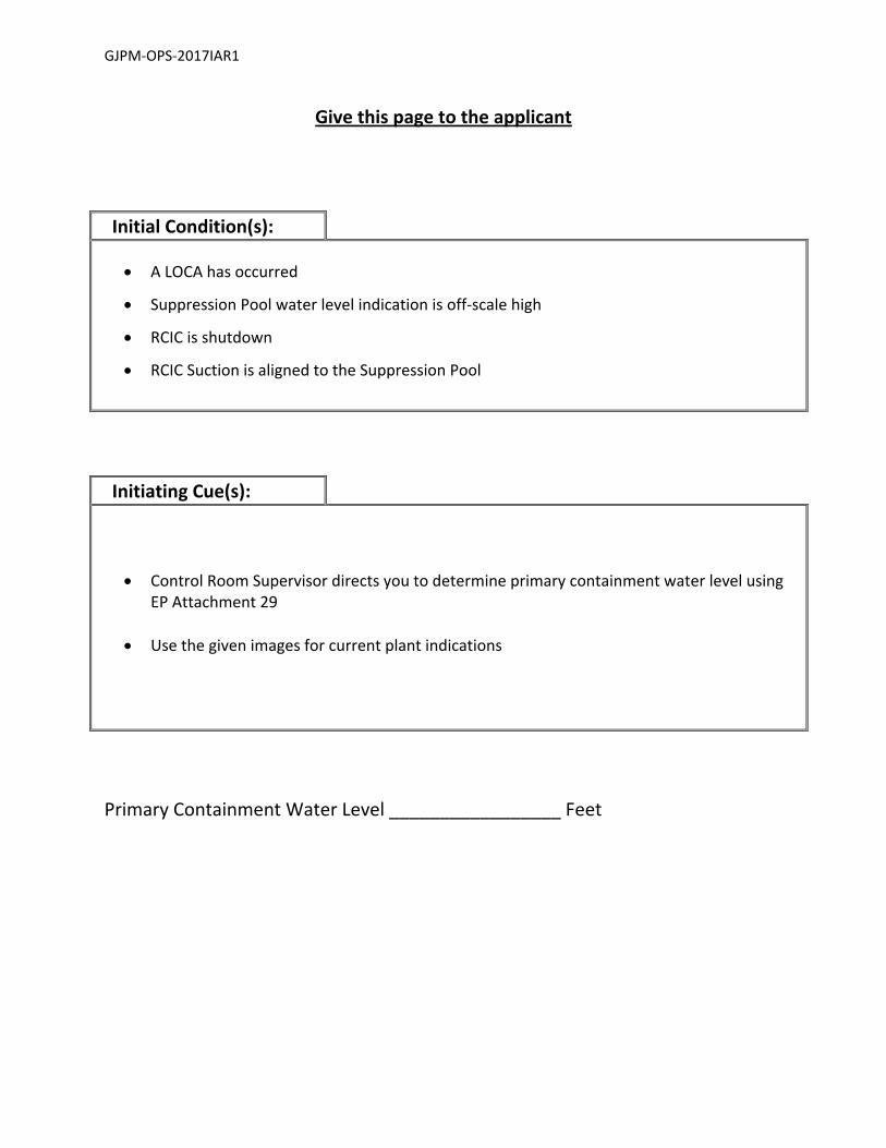
Initial Condition(s):
A LOCA has occurred
Suppression Pool water level indication is off‐scale high
RCIC is shutdown
RCIC Suction is aligned to the Suppression Pool
Initiating Cue(s):
Control Room Supervisor directs you to determine primary containment water level using EP Attachment 29
Use the given images for current plant indications
Date of Examination: 12/04/2017
Operating Test Number: GGNS 12‐2017
Facility: Grand Gulf Nuclear Station
JPM Number: GJPM‐OPS‐2017IAR1
Rev. 01 11/06/2017 Page 4 of 11
Determine Primary Containment Water Level Notes to Evaluator:
None
Task Overview: (Detailed description of task)
Using EP Attachment 29 and the attached images to obtain RCIC Suction Pressure and Containment Pressure, determine Primary Containment Water Level from the Delta Pressure to Ctmt Level Conversion Table, EP Attachment 29 Table 1. This task would be performed post event when Suppression Pool Level Instruments and Containment Water Level Instruments are not working to determine Primary Containment Water Level.
Tasks: Critical steps are shaded, bolded, italicized, and denoted by an (*) Note: Steps are not sequence critical. Applicant will have to obtain information and complete calculations. Step 1: 05‐S‐01‐EP‐1, Att. 29, Step 2.1 ‐ 2.3
Determines from turnover information that steps 2.1 through 2.3 are complete.
Standard: Determined from turnover information that steps 2.1 through 2.3 were able to be completed.
Cue: None
Notes: None
SAT / UNSAT
Date of Examination: 12/04/2017
Operating Test Number: GGNS 12‐2017
Facility: Grand Gulf Nuclear Station
JPM Number: GJPM‐OPS‐2017IAR1
Rev. 01 11/06/2017 Page 5 of 11
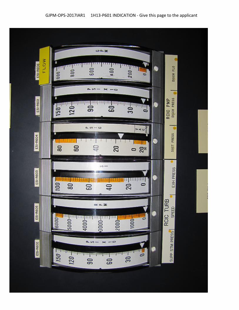
Step 2: 05‐S‐01‐EP‐1, Att. 29, Step 2.4
* Obtain RCIC PMP SUCT PRESS (E51‐R604 on 1H13‐P601).
Standard: Using the given photo of 1H13‐P601‐21B, applicant located the correct indicator (E51‐R604) and determined it was indicating 15 psig. Applicant also recorded 15 psig on Attachment 29 step 2.4.
Cue: None
Notes: None
SAT / UNSAT
Step 3: 05‐S‐01‐EP‐1, Att. 29, Step 2.5
* Obtain Containment pressure (psig) from SPDS or Post Accident recorders on 1H13‐P870.
Standard: Applicant determined Containment Pressure indicated on the SPDS
display from image 2 was 2.2 psig and recorded it on EP Attachment
29 step 2.5.
Cue: None
Notes: None
SAT / UNSAT
Date of Examination: 12/04/2017
Operating Test Number: GGNS 12‐2017
Facility: Grand Gulf Nuclear Station
JPM Number: GJPM‐OPS‐2017IAR1
Rev. 01 11/06/2017 Page 6 of 11
Step 4: 05‐S‐01‐EP‐1, Att. 29, Step 2.6
* Subtract Containment pressure from RCIC suction pressure (Delta Pressure).
Standard: Applicant determined Delta Pressure to be 12.8 psid by subtracting
Containment Pressure recorded in step 2.5 from RCIC Pump Suction
Pressure recorded in step 2.4 and records it in step 2.6
Cue: None
Notes: 15 psig ‐ 2.2 psig = 12.8 psid
SAT / UNSAT
Step 5: 05‐S‐01‐EP‐1, Att. 29, Step 2.7
* Determine Containment level, using pressure obtained in Step 2.6 and Table 1.
Standard: Applicant determined Primary Containment water level using EP
Attachment 29 Table 1 by moving down the Delta Pressure whole
number column to 12 and then to the right to the 0.8, Tenths of
Pound Delta Pressure column, which lists Containment Level as 35.5
feet.
Cue: None
Notes: None
SAT / UNSAT

Date of Examination: 12/04/2017
Operating Test Number: GGNS 12‐2017
Facility: Grand Gulf Nuclear Station
JPM Number: GJPM‐OPS‐2017IAR1
Rev. 01 11/06/2017 Page 7 of 11
Task Standard(s):
Determined RCIC Pump Suction Pressure was 15 psig
Determined Containment Pressure was 2.2 psig
Determined differential pressure between Containment and RCIC Pump Suction Pressure
was 12.8 psid
Primary Containment water level using containment pressure, RCIC suction pressure and
05‐S‐01‐EP‐1 Attachment 29 determined to be 35.5 Feet.
SAT / UNSAT
Remember to record stop time
Date of Examination: 12/04/2017
Operating Test Number: GGNS 12‐2017
Facility: Grand Gulf Nuclear Station
JPM Number: GJPM‐OPS‐2017IAR1
Rev. 01 11/06/2017 Page 8 of 11
Follow-Up Questions & Answers:
Comments:
GJPM‐OPS‐2017IAR1
Give this page to the applicant
Initial Condition(s):
A LOCA has occurred
Suppression Pool water level indication is off‐scale high
RCIC is shutdown
RCIC Suction is aligned to the Suppression Pool
Initiating Cue(s):
Control Room Supervisor directs you to determine primary containment water level using EP Attachment 29
Use the given images for current plant indications
Primary Containment Water Level _________________ Feet

GJPM‐OPS‐2017IAR1 SPDS Display ‐ Give this page to the applicant
GJPM‐OPS‐2017IAR1 1H13‐P601 INDICATION ‐ Give this page to the applicant
Date of Examination: 12/04/2017
Operating Test Number: GGNS 12‐2017
Facility: Grand Gulf Nuclear Station
JPM Number: GJPM‐OPS‐2017IAR2
Rev. 01 11/06/2017 Page 1 of 11
2017I AR2
GGNS
2017 NRC Operating Test
Job Performance Measure
JPM Number: GJPM‐OPS‐2017IAR2 JPM Title: Perform AC Lineup
Surveillance Facility Number: GJPM‐RO‐ADM‐1A (If Bank or Modified from Bank)
JPM Attributes:
New Modified Direct from bank
Time Critical Alternate Path Validation Time: 15 min
Prepared By: Michael Rasch 11/06/2017
Exam Developer Date
Ops Review: Robert Brinkman 11/06/2017
1st Validation by Ops Rep or Ops Validation Crew Date
Validated By: Benny White \ Chase Miller 11/06/2017
2nd Validation by Ops Validation Crew Date
Approved By: Ricky Liddell 11/06/2017
Project Lead or Exam Team Lead Date
Date of Examination: 12/04/2017
Operating Test Number: GGNS 12‐2017
Facility: Grand Gulf Nuclear Station
JPM Number: GJPM‐OPS‐2017IAR2
Rev. 01 11/06/2017 Page 2 of 11
Perform AC Lineup Surveillance
Time Critical Alternate Path Validation Time: 15 Min
Setting: Simulator
Type: RO/ SRO
Task: CRO‐R20/27‐NORMAL‐8
K&A: Generic 2.1.31 (4.6/4.3); 2.2.12 (3.7/4.1); 2.1.20 (4.6/4.6)
Safety Function: Generic ‐ Conduct of Operations
PRA Applicability: No
10 CFR 55.45(a) (12); (13)
Performance: Perform
Reference(s): 06‐OP‐1R20‐W‐0001 Rev. 109, Plant AC and DC Electrical
Power Distribution Weekly Lineup
Handout(s): 06‐OP‐1R20‐W‐0001 marked with Radiation Protection Review
Calculator
# Manipulations: N/A
# Critical Steps: 1
ADMINISTRATIVE JPM
Simulator Setup/Required Plant Conditions:
Setup Simulator in IC ‐ 1
Place Division 3 Diesel Generator in Maintenance remote function p81059
Safety Concerns:
None
Date of Examination: 12/04/2017
Operating Test Number: GGNS 12‐2017
Facility: Grand Gulf Nuclear Station
JPM Number: GJPM‐OPS‐2017IAR2
Rev. 01 11/06/2017 Page 3 of 11
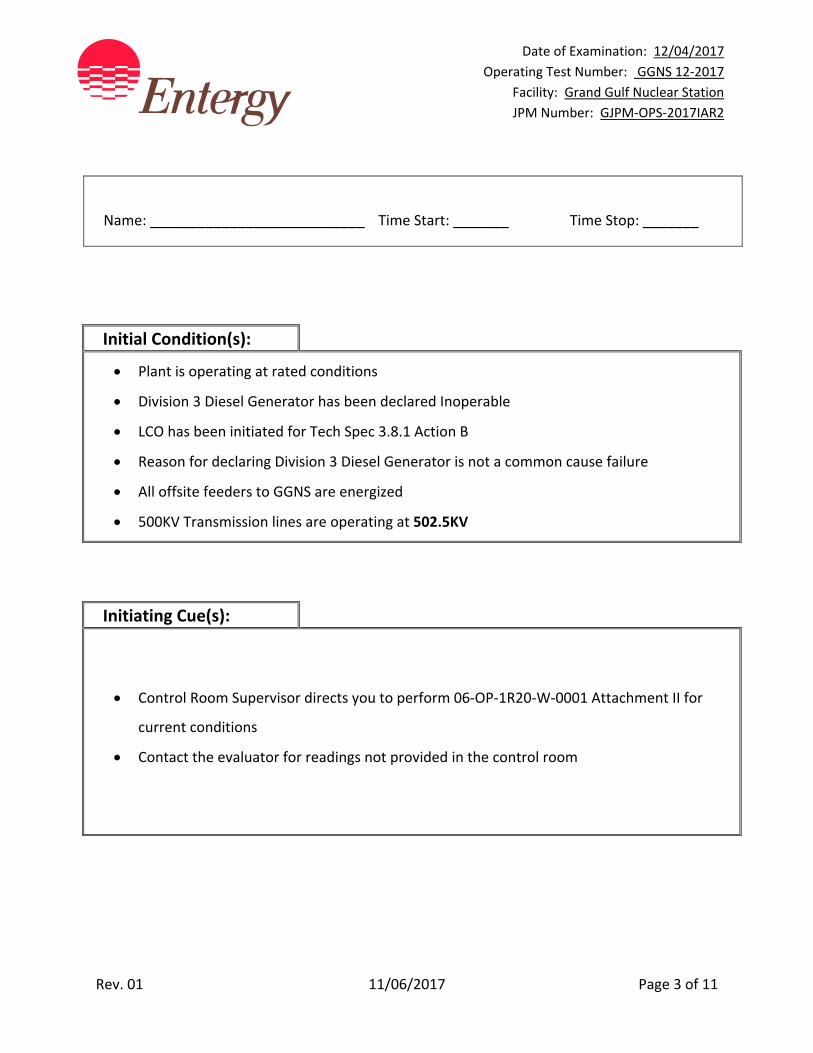
Name: ___________________________ Time Start: _______ Time Stop: _______
Initial Condition(s):
Plant is operating at rated conditions
Division 3 Diesel Generator has been declared Inoperable
LCO has been initiated for Tech Spec 3.8.1 Action B
Reason for declaring Division 3 Diesel Generator is not a common cause failure
All offsite feeders to GGNS are energized
500KV Transmission lines are operating at 502.5KV
Initiating Cue(s):
Control Room Supervisor directs you to perform 06‐OP‐1R20‐W‐0001 Attachment II for
current conditions
Contact the evaluator for readings not provided in the control room
Date of Examination: 12/04/2017
Operating Test Number: GGNS 12‐2017
Facility: Grand Gulf Nuclear Station
JPM Number: GJPM‐OPS‐2017IAR2
Rev. 01 11/06/2017 Page 4 of 11
Perform AC Lineup Surveillance Notes to Evaluator:
JPM should be performed in the Simulator which replicates plant conditions.
Task Overview: (Detailed description of task)
This task is performed any time a diesel generator is declared inoperable. Surveillance 06‐OP‐1R20‐W‐0001 Plant AC and DC Electrical Power Distribution Weekly Lineup is performed to verify electrical distribution for Tech Specs 3.8.1; 3.8.2; 3.8.7 and 3.8.8. Attachment I is the normal full surveillance. Attachment II is performed to meet Surveillance Requirement SR3.8.1.1.
Date of Examination: 12/04/2017
Operating Test Number: GGNS 12‐2017
Facility: Grand Gulf Nuclear Station
JPM Number: GJPM‐OPS‐2017IAR2
Rev. 01 11/06/2017 Page 5 of 11
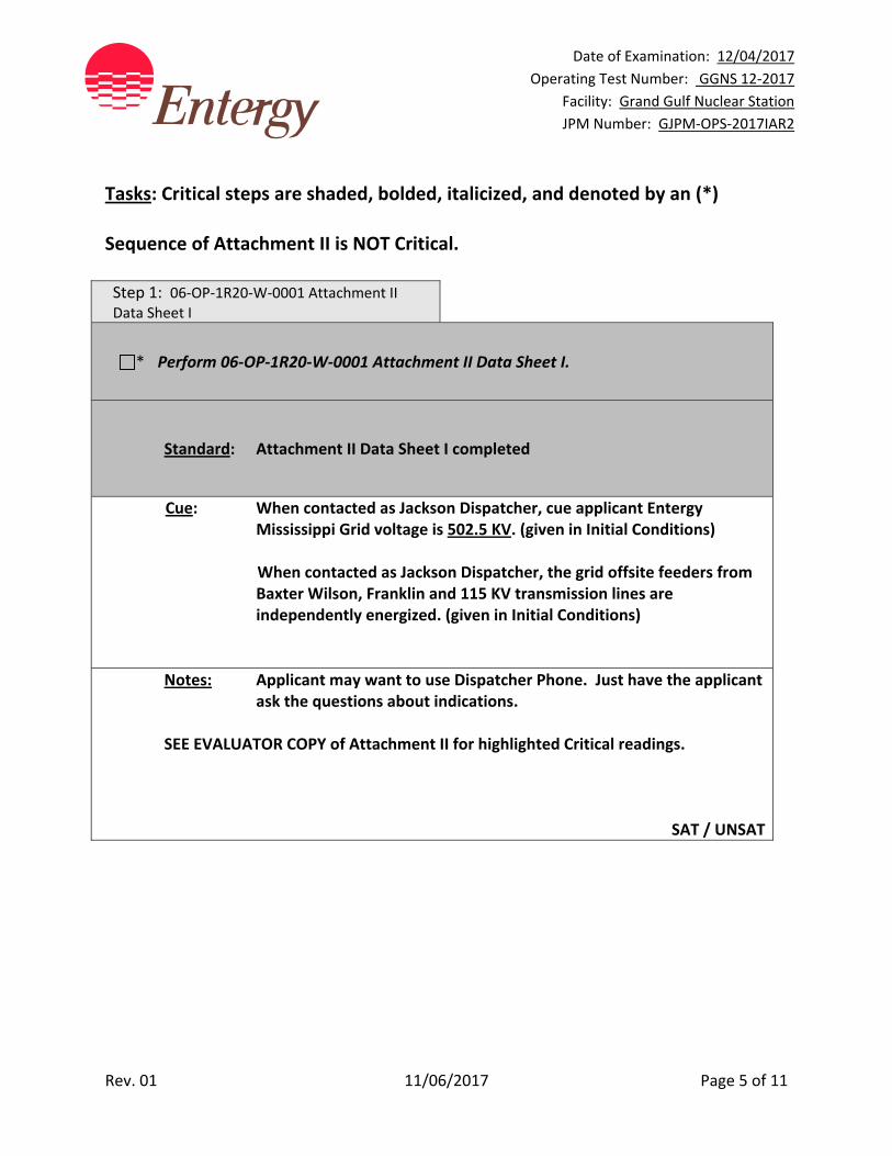
Tasks: Critical steps are shaded, bolded, italicized, and denoted by an (*) Sequence of Attachment II is NOT Critical. Step 1: 06‐OP‐1R20‐W‐0001 Attachment II Data Sheet I
* Perform 06‐OP‐1R20‐W‐0001 Attachment II Data Sheet I.
Standard: Attachment II Data Sheet I completed
Cue: When contacted as Jackson Dispatcher, cue applicant Entergy Mississippi Grid voltage is 502.5 KV. (given in Initial Conditions)
When contacted as Jackson Dispatcher, the grid offsite feeders from Baxter Wilson, Franklin and 115 KV transmission lines are independently energized. (given in Initial Conditions)
Notes: Applicant may want to use Dispatcher Phone. Just have the applicant ask the questions about indications.
SEE EVALUATOR COPY of Attachment II for highlighted Critical readings.
SAT / UNSAT
Date of Examination: 12/04/2017
Operating Test Number: GGNS 12‐2017
Facility: Grand Gulf Nuclear Station
JPM Number: GJPM‐OPS‐2017IAR2
Rev. 01 11/06/2017 Page 6 of 11
Task Standard(s):
Applicable portions of Plant AC Electrical Power Distribution Weekly Lineup Surveillance 06‐OP‐1R20‐W‐0001 Attachment II are completed and any discrepancies noted. (See Evaluator Copy Highlighted sections for critical items)
SAT / UNSAT
Remember to record stop time

Date of Examination: 12/04/2017
Operating Test Number: GGNS 12‐2017
Facility: Grand Gulf Nuclear Station
JPM Number: GJPM‐OPS‐2017IAR2
Rev. 01 11/06/2017 Page 7 of 11
Follow-Up Questions & Answers:
Comments:
GJPM‐OPS‐2017IAR2
Give this page to the applicant
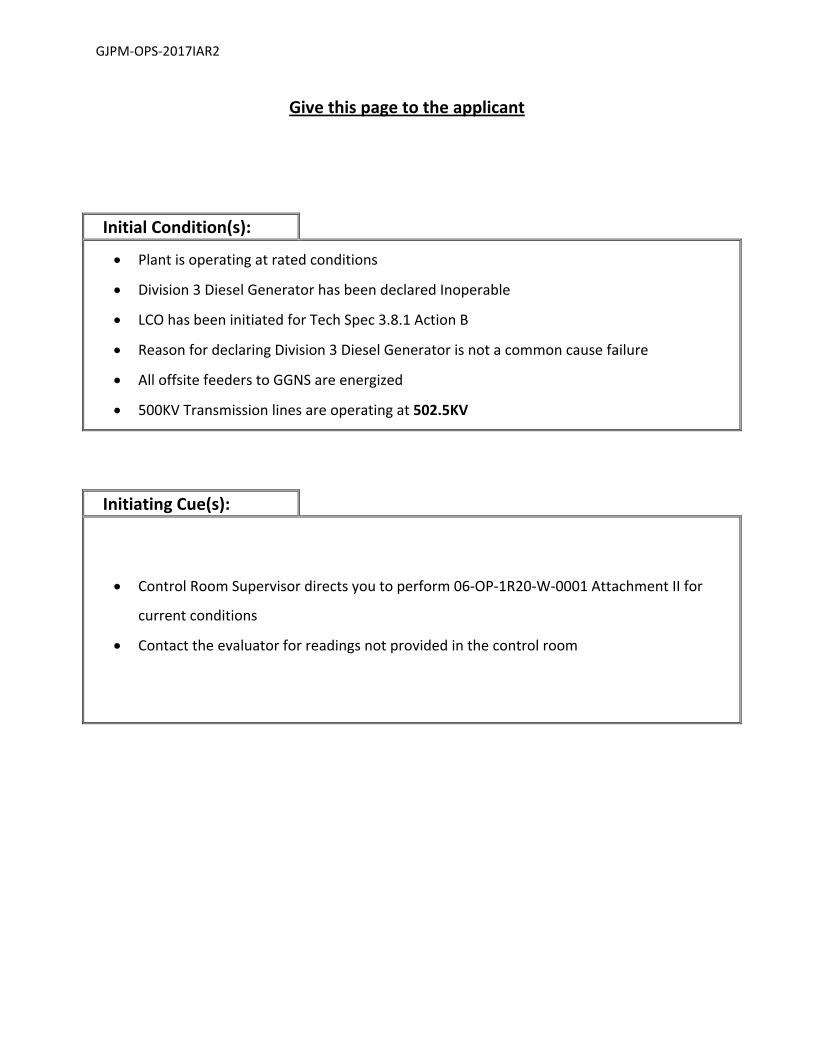
Initial Condition(s):
Plant is operating at rated conditions
Division 3 Diesel Generator has been declared Inoperable
LCO has been initiated for Tech Spec 3.8.1 Action B
Reason for declaring Division 3 Diesel Generator is not a common cause failure
All offsite feeders to GGNS are energized
500KV Transmission lines are operating at 502.5KV
Initiating Cue(s):
Control Room Supervisor directs you to perform 06‐OP‐1R20‐W‐0001 Attachment II for
current conditions
Contact the evaluator for readings not provided in the control room

GJPM‐OPS‐2017IAR2
GJPM‐OPS‐2017IAR2
GJPM‐OPS‐2017IAR2

J:\ADM_SRVS\TECH_PUB\REVISION\O\or20w01.doc
GRAND GULF NUCLEAR STATION SURVEILLANCE PROCEDURE 06-OP-1R20-W-0001 Revision 109 Attachment II Page 1 of 4 Model WO# 50289936 XRef
SURVEILLANCE PROCEDURE DATA PACKAGE COVER SHEET
SAFETY RELATED Title: Plant AC and DC Electrical Power Distribution Weekly Lineup Technical Specifications: SR 3.8.1.1 1.0 IMPACT STATEMENT 1.1 Performance of this procedure has no impact on plant operation. 2.0 PROCEDURE 2.1 Plant Mode is (circle one): 1 2 3 2.2 Test Start Time / / Performer / Date Time
2.3 Radiation Protection Review RWP # 3.0 TEST RESULTS 3.1 Test Completion: (CHECK one in each category.) Entire procedure completed [ ] Partial procedure completed [ ] Tech Spec Acceptance Criteria Acceptable [ ] Unacceptable [ ] All other steps/data Acceptable [ ] Unacceptable [ ] 3.2 Inop Electrical Equipment (include LCO #) 3.3 Comments: 3.4 Test performed by Date/Time / 4.0 DEFICIENCIES CR Issued # LCO Entered # WR Issued # 5.0 APPROVAL Tech Spec Operability Requirements Acceptable [ ] Unacceptable [ ] Shift Supervision Date CONCURRENCE Operations Management Date
GRAND GULF NUCLEAR STATION SURVEILLANCE PROCEDURE
06-OP-1R20-W-0001 Revision 109 Attachment II Page 2 of 4
Page XRef
J:\ADM_SRVS\TECH_PUB\REVISION\O\or20w01.doc
DATA SHEET I PLANT AC AND DC ELECTRICAL POWER DISTRIBUTION
WEEKLY LINEUP SAFETY RELATED
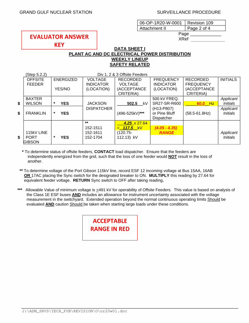
(Step 5.2.2) Div 1, 2 & 3 Offsite Feeders
OFFSITE ENERGIZED VOLTAGE RECORDED FREQUENCY RECORDED INITIALS FEEDER INDICATOR VOLTAGE INDICATOR FREQUENCY YES/NO (LOCATION) (ACCEPTANCE (LOCATION) (ACCEPTANCE CRITERIA) CRITERIA) BAXTER 500 kV FREQ. Applicant $ WILSON * YES JACKSON 502.5 kV SR27-SR-R600 60.0 Hz Initials DISPATCHER (H13-P807) Applicant $ FRANKLIN * YES (496-525kV)*** or Pine Bluff
Dispatcher (58.5-61.8Hz) Initials
** 4.25 x 27.64 152-1511 = 117.5 kV (4.05 - 4.35) 115kV LINE 152-1611 (120.75- RANGE Applicant $ PORT
GIBSON * YES 152-1704 112.13) kV Initials
* To determine status of offsite feeders, CONTACT load dispatcher. Ensure that the feeders are independently energized from the grid, such that the loss of one feeder would NOT result in the loss of another.
** To determine voltage of the Port Gibson 115kV line, record ESF 12 incoming voltage at Bus 15AA, 16AB OR 17AC placing the Sync switch for the designated breaker to ON. MULTIPLY this reading by 27.64 for equivalent feeder voltage. RETURN Sync switch to OFF after taking reading.
*** Allowable Value of minimum voltage is >491 kV for operability of Offsite Feeders. This value is based on analysis of
the Class 1E ESF buses AND includes an allowance for instrument uncertainty associated with the voltage measurement in the switchyard. Extended operation beyond the normal continuous operating limits Should be evaluated AND caution Should be taken when starting large loads under these conditions.
EVALUATOR ANSWER KEY
ACCEPTABLE RANGE IN RED
GRAND GULF NUCLEAR STATION SURVEILLANCE PROCEDURE
06-OP-1R20-W-0001 Revision 109 Attachment II Page 3 of 4
Page XRef
J:\ADM_SRVS\TECH_PUB\REVISION\O\or20w01.doc
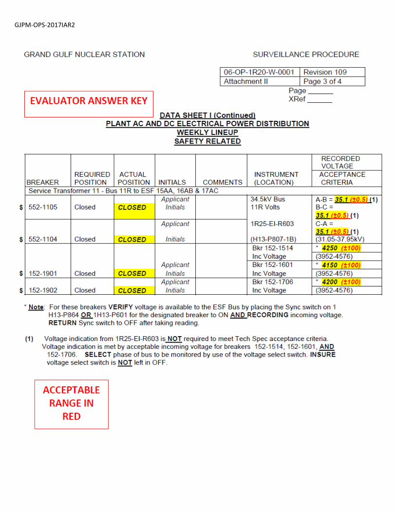
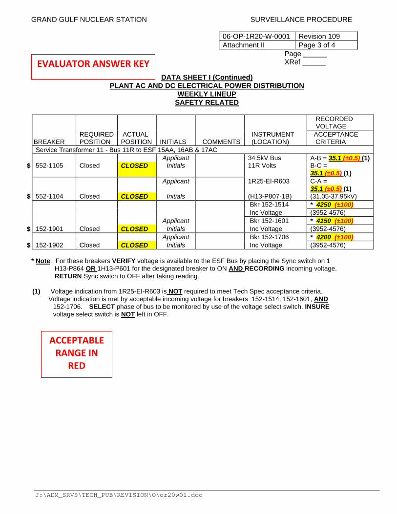
DATA SHEET I (Continued) PLANT AC AND DC ELECTRICAL POWER DISTRIBUTION
WEEKLY LINEUP SAFETY RELATED
RECORDED VOLTAGE REQUIRED ACTUAL INSTRUMENT ACCEPTANCE BREAKER POSITION POSITION INITIALS COMMENTS (LOCATION) CRITERIA Service Transformer 11 - Bus 11R to ESF 15AA, 16AB & 17AC Applicant 34.5kV Bus A-B = 35.1 (±0.5) (1)$ 552-1105 Closed CLOSED Initials 11R Volts B-C =
35.1 (±0.5) (1) Applicant 1R25-EI-R603 C-A =
35.1 (±0.5) (1) $ 552-1104 Closed CLOSED Initials (H13-P807-1B) (31.05-37.95kV) Bkr 152-1514 * 4250 (±100) Inc Voltage (3952-4576) Applicant Bkr 152-1601 * 4150 (±100) $ 152-1901 Closed CLOSED Initials Inc Voltage (3952-4576) Applicant Bkr 152-1706 * 4200 (±100) $ 152-1902 Closed CLOSED Initials Inc Voltage (3952-4576)
* Note: For these breakers VERIFY voltage is available to the ESF Bus by placing the Sync switch on 1 H13-P864 OR 1H13-P601 for the designated breaker to ON AND RECORDING incoming voltage. RETURN Sync switch to OFF after taking reading.
(1) Voltage indication from 1R25-EI-R603 is NOT required to meet Tech Spec acceptance criteria. Voltage indication is met by acceptable incoming voltage for breakers 152-1514, 152-1601, AND
152-1706. SELECT phase of bus to be monitored by use of the voltage select switch. INSURE voltage select switch is NOT left in OFF.
EVALUATOR ANSWER KEY
ACCEPTABLE RANGE IN
RED
GRAND GULF NUCLEAR STATION SURVEILLANCE PROCEDURE
06-OP-1R20-W-0001 Revision 109 Attachment II Page 4 of 4
Page XRef
J:\ADM_SRVS\TECH_PUB\REVISION\O\or20w01.doc
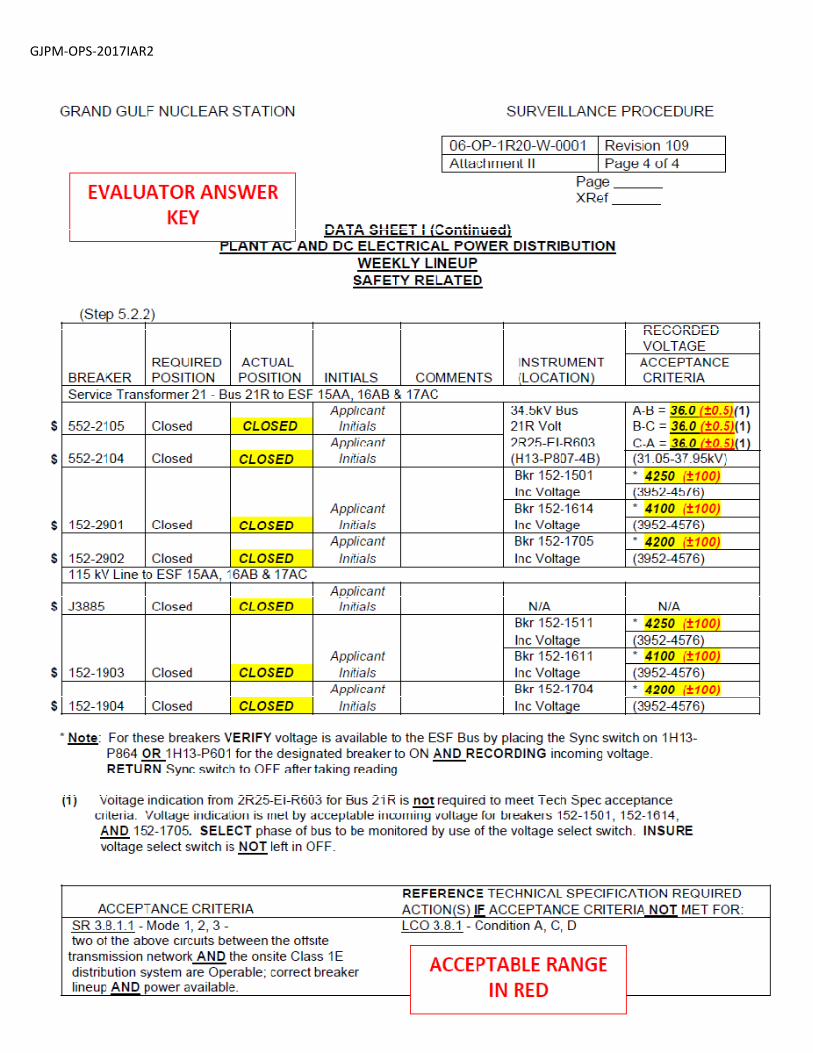
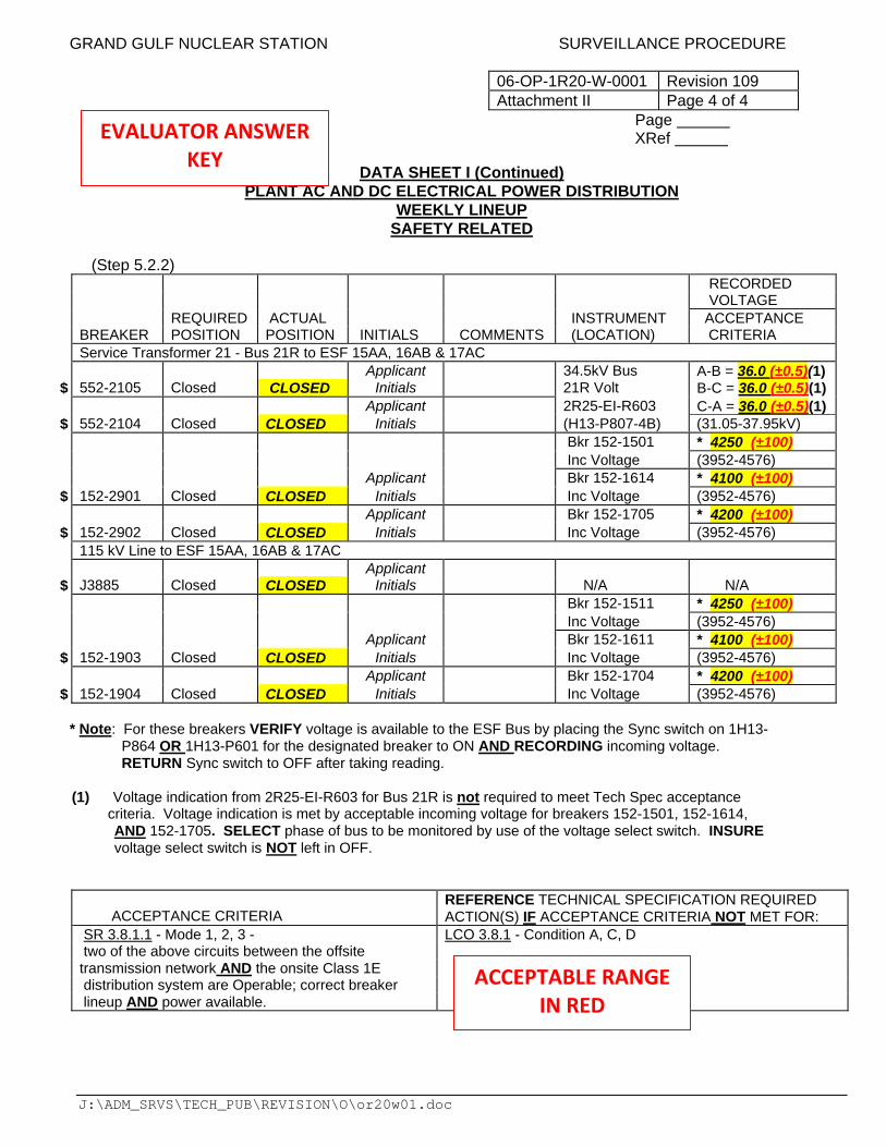
DATA SHEET I (Continued) PLANT AC AND DC ELECTRICAL POWER DISTRIBUTION
WEEKLY LINEUP SAFETY RELATED
(Step 5.2.2)
RECORDED VOLTAGE REQUIRED ACTUAL INSTRUMENT ACCEPTANCE BREAKER POSITION POSITION INITIALS COMMENTS (LOCATION) CRITERIA Service Transformer 21 - Bus 21R to ESF 15AA, 16AB & 17AC Applicant 34.5kV Bus A-B = 36.0 (±0.5)(1) $ 552-2105 Closed CLOSED Initials 21R Volt B-C = 36.0 (±0.5)(1) Applicant 2R25-EI-R603 C-A = 36.0 (±0.5)(1) $ 552-2104 Closed CLOSED Initials (H13-P807-4B) (31.05-37.95kV) Bkr 152-1501 * 4250 (±100) Inc Voltage (3952-4576) Applicant Bkr 152-1614 * 4100 (±100) $ 152-2901 Closed CLOSED Initials Inc Voltage (3952-4576) Applicant Bkr 152-1705 * 4200 (±100) $ 152-2902 Closed CLOSED Initials Inc Voltage (3952-4576) 115 kV Line to ESF 15AA, 16AB & 17AC Applicant $ J3885 Closed CLOSED Initials N/A N/A Bkr 152-1511 * 4250 (±100) Inc Voltage (3952-4576) Applicant Bkr 152-1611 * 4100 (±100) $ 152-1903 Closed CLOSED Initials Inc Voltage (3952-4576) Applicant Bkr 152-1704 * 4200 (±100) $ 152-1904 Closed CLOSED Initials Inc Voltage (3952-4576)
* Note: For these breakers VERIFY voltage is available to the ESF Bus by placing the Sync switch on 1H13- P864 OR 1H13-P601 for the designated breaker to ON AND RECORDING incoming voltage. RETURN Sync switch to OFF after taking reading. (1) Voltage indication from 2R25-EI-R603 for Bus 21R is not required to meet Tech Spec acceptance criteria. Voltage indication is met by acceptable incoming voltage for breakers 152-1501, 152-1614, AND 152-1705. SELECT phase of bus to be monitored by use of the voltage select switch. INSURE voltage select switch is NOT left in OFF.
ACCEPTANCE CRITERIA
REFERENCE TECHNICAL SPECIFICATION REQUIRED ACTION(S) IF ACCEPTANCE CRITERIA NOT MET FOR:
SR 3.8.1.1 - Mode 1, 2, 3 - LCO 3.8.1 - Condition A, C, D two of the above circuits between the offsite transmission network AND the onsite Class 1E distribution system are Operable; correct breaker lineup AND power available.
EVALUATOR ANSWER KEY
ACCEPTABLE RANGE IN RED
Date of Examination: 12/04/2017
Operating Test Number: GGNS 12‐2017
Facility: Grand Gulf Nuclear Station
JPM Number: GJPM‐OPS‐2017IAR3
Rev. 02 11/29/2017 Page 1 of 12
2017I AR3
GGNS
2017 NRC Operating Test
Job Performance Measure
JPM Number: GJPM‐OPS‐2017IAR3 JPM Title: Determine Tagging Requirements
Facility Number: _GJPM‐OPS‐AAD04_ (If Bank or Modified from Bank)
JPM Attributes:
New Modified Direct from bank
Time Critical Alternate Path Validation Time: 30 min
Prepared By: Michael Rasch 11/06/2017
Exam Developer Date
Ops Review: Robert Brinkman 11/06/2017
1st Validation by Ops Rep or Ops Validation Crew Date
Validated By: Benny White \ Chase Miller 11/06/2017
2nd Validation by Ops Validation Crew Date
Approved By: Ricky Liddell 11/06/2017
Project Lead or Exam Team Lead Date
Date of Examination: 12/04/2017
Operating Test Number: GGNS 12‐2017
Facility: Grand Gulf Nuclear Station
JPM Number: GJPM‐OPS‐2017IAR3
Rev. 02 11/29/2017 Page 2 of 12
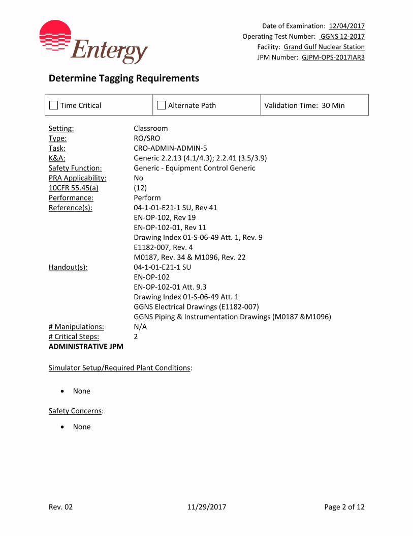
Determine Tagging Requirements
Time Critical Alternate Path Validation Time: 30 Min
Setting: Classroom Type: RO/SRO Task: CRO‐ADMIN‐ADMIN‐5 K&A: Generic 2.2.13 (4.1/4.3); 2.2.41 (3.5/3.9) Safety Function: Generic ‐ Equipment Control Generic PRA Applicability: No 10CFR 55.45(a) (12) Performance: Perform Reference(s): 04‐1‐01‐E21‐1 SU, Rev 41 EN‐OP‐102, Rev 19 EN‐OP‐102‐01, Rev 11 Drawing Index 01‐S‐06‐49 Att. 1, Rev. 9 E1182‐007, Rev. 4 M0187, Rev. 34 & M1096, Rev. 22 Handout(s): 04‐1‐01‐E21‐1 SU EN‐OP‐102 EN‐OP‐102‐01 Att. 9.3 Drawing Index 01‐S‐06‐49 Att. 1 GGNS Electrical Drawings (E1182‐007) GGNS Piping & Instrumentation Drawings (M0187 &M1096) # Manipulations: N/A # Critical Steps: 2 ADMINISTRATIVE JPM
Simulator Setup/Required Plant Conditions:
None
Safety Concerns:
None
Date of Examination: 12/04/2017
Operating Test Number: GGNS 12‐2017
Facility: Grand Gulf Nuclear Station
JPM Number: GJPM‐OPS‐2017IAR3
Rev. 02 11/29/2017 Page 3 of 12
Name: ___________________________ Time Start: _______ Time Stop: _______
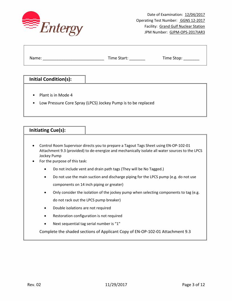
Initial Condition(s):
• Plant is in Mode 4
• Low Pressure Core Spray (LPCS) Jockey Pump is to be replaced
Initiating Cue(s):
Control Room Supervisor directs you to prepare a Tagout Tags Sheet using EN‐OP‐102‐01 Attachment 9.3 (provided) to de‐energize and mechanically isolate all water sources to the LPCS Jockey Pump
For the purpose of this task:
Do not include vent and drain path tags (They will be No Tagged.)
Do not use the main suction and discharge piping for the LPCS pump (e.g. do not use
components on 14 inch piping or greater)
Only consider the isolation of the jockey pump when selecting components to tag (e.g.
do not rack out the LPCS pump breaker)
Double isolations are not required
Restoration configuration is not required
Next sequential tag serial number is “1”
Complete the shaded sections of Applicant Copy of EN‐OP‐102‐01 Attachment 9.3
Date of Examination: 12/04/2017
Operating Test Number: GGNS 12‐2017
Facility: Grand Gulf Nuclear Station
JPM Number: GJPM‐OPS‐2017IAR3
Rev. 02 11/29/2017 Page 4 of 12
Determine Tagging Requirements
Notes to Evaluator:
This is an Administrative JPM and can be performed in a classroom.
Task Overview: (Detailed description of task)
This task is to use facility electrical and mechanical drawings to determine the protective tagging boundaries for a task. Reactor Operators perform the duties of tagout preparers to determine and review boundaries.
Date of Examination: 12/04/2017
Operating Test Number: GGNS 12‐2017
Facility: Grand Gulf Nuclear Station
JPM Number: GJPM‐OPS‐2017IAR3
Rev. 02 11/29/2017 Page 5 of 12
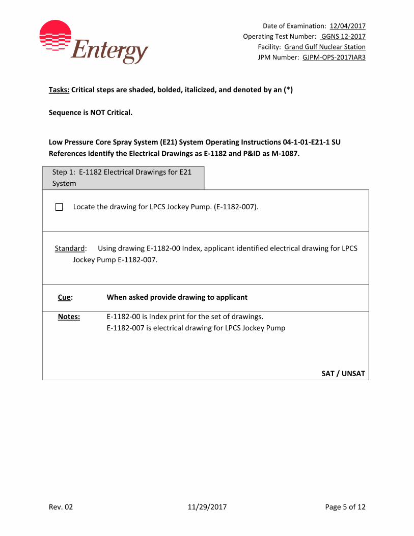
Tasks: Critical steps are shaded, bolded, italicized, and denoted by an (*)
Sequence is NOT Critical.
Low Pressure Core Spray System (E21) System Operating Instructions 04‐1‐01‐E21‐1 SU
References identify the Electrical Drawings as E‐1182 and P&ID as M‐1087.
Step 1: E‐1182 Electrical Drawings for E21
System
Locate the drawing for LPCS Jockey Pump. (E‐1182‐007).
Standard: Using drawing E‐1182‐00 Index, applicant identified electrical drawing for LPCS
Jockey Pump E‐1182‐007.
Cue: When asked provide drawing to applicant
Notes: E‐1182‐00 is Index print for the set of drawings.
E‐1182‐007 is electrical drawing for LPCS Jockey Pump
SAT / UNSAT

Date of Examination: 12/04/2017
Operating Test Number: GGNS 12‐2017
Facility: Grand Gulf Nuclear Station
JPM Number: GJPM‐OPS‐2017IAR3
Rev. 02 11/29/2017 Page 6 of 12
Step 2: M‐1087 Mechanical Drawings
(P&ID) for E21 System
Locate mechanical drawing for LPCS Jockey Pump P&ID M‐1087.
Standard: Applicant identified mechanical drawing for LPCS Jockey Pump P&ID M‐1087.
Cue: When asked provide drawing to applicant
Notes: M‐1087 is mechanical drawing for LPCS Jockey Pump
SAT / UNSAT
Date of Examination: 12/04/2017
Operating Test Number: GGNS 12‐2017
Facility: Grand Gulf Nuclear Station
JPM Number: GJPM‐OPS‐2017IAR3
Rev. 02 11/29/2017 Page 7 of 12
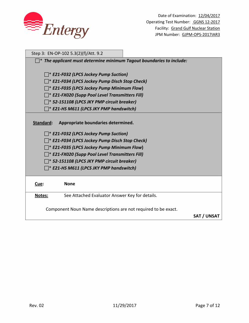
Step 3: EN‐OP‐102 5.3(2)(f)/Att. 9.2
* The applicant must determine minimum Tagout boundaries to include:
* E21‐F032 (LPCS Jockey Pump Suction)
* E21‐F034 (LPCS Jockey Pump Disch Stop Check)
* E21‐F035 (LPCS Jockey Pump Minimum Flow)
* E21‐FX020 (Supp Pool Level Transmitters Fill)
* 52‐151108 (LPCS JKY PMP circuit breaker)
* E21‐HS M611 (LPCS JKY PMP handswitch)
Standard: Appropriate boundaries determined.
* E21‐F032 (LPCS Jockey Pump Suction)
* E21‐F034 (LPCS Jockey Pump Disch Stop Check)
* E21‐F035 (LPCS Jockey Pump Minimum Flow)
* E21‐FX020 (Supp Pool Level Transmitters Fill)
* 52‐151108 (LPCS JKY PMP circuit breaker)
* E21‐HS M611 (LPCS JKY PMP handswitch)
Cue: None
Notes: See Attached Evaluator Answer Key for details.
Component Noun Name descriptions are not required to be exact.
SAT / UNSAT
Date of Examination: 12/04/2017
Operating Test Number: GGNS 12‐2017
Facility: Grand Gulf Nuclear Station
JPM Number: GJPM‐OPS‐2017IAR3
Rev. 02 11/29/2017 Page 8 of 12
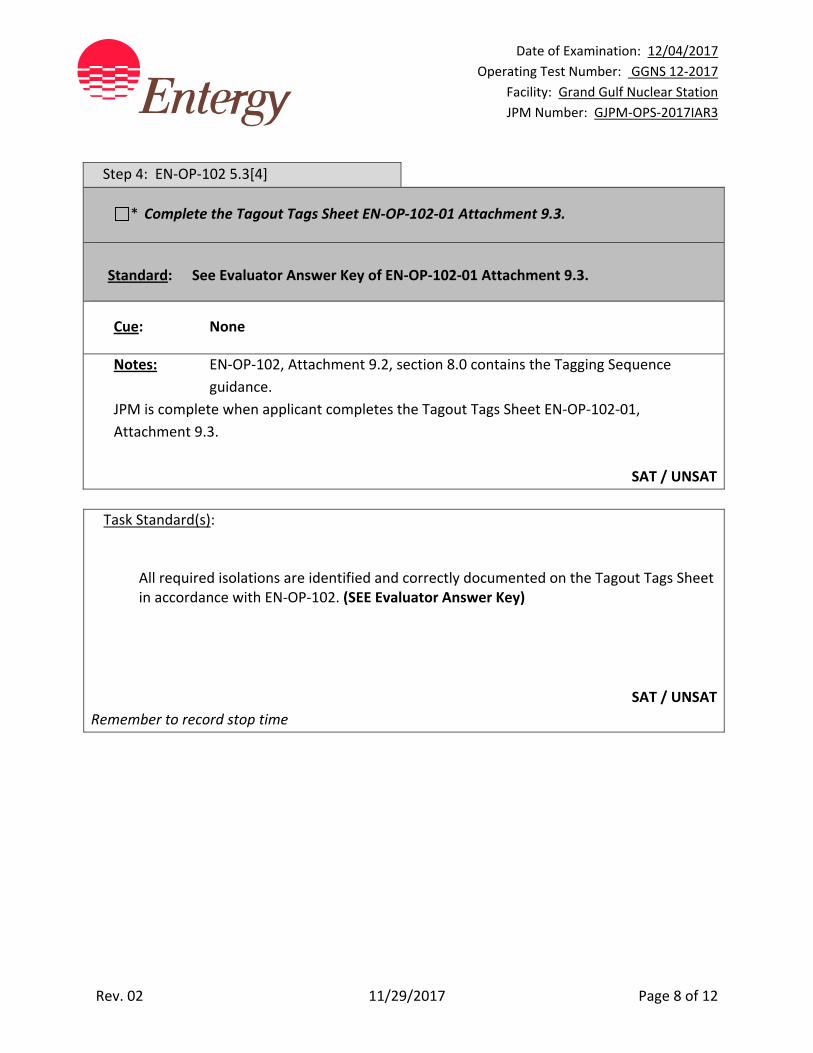
Step 4: EN‐OP‐102 5.3[4]
* Complete the Tagout Tags Sheet EN‐OP‐102‐01 Attachment 9.3.
Standard: See Evaluator Answer Key of EN‐OP‐102‐01 Attachment 9.3.
Cue: None
Notes: EN‐OP‐102, Attachment 9.2, section 8.0 contains the Tagging Sequence
guidance.
JPM is complete when applicant completes the Tagout Tags Sheet EN‐OP‐102‐01,
Attachment 9.3.
SAT / UNSAT
Task Standard(s):
All required isolations are identified and correctly documented on the Tagout Tags Sheet in accordance with EN‐OP‐102. (SEE Evaluator Answer Key)
SAT / UNSAT
Remember to record stop time

Date of Examination: 12/04/2017
Operating Test Number: GGNS 12‐2017
Facility: Grand Gulf Nuclear Station
JPM Number: GJPM‐OPS‐2017IAR3
Rev. 02 11/29/2017 Page 9 of 12
Follow-Up Questions & Answers:
Comments:

GJPM‐OPS‐2017IAR3
NUCLEAR MANAGEMENT
MANUAL NON‐QUALITY RELATED EN‐OP‐102‐01 REV. 11
INFORMATIONAL USE PAGE 10 OF 12
Protective and Caution Tagging Forms & Checklist
ATTACHMENT 9.3 TAGOUT TAGS SHEET
Clearance: ____MANUAL______________ Tagout: _____XXX_______
Tag
Serial
No.
Tag
Type
Equipment
Equipment Description
Equipment Location
Place.
Seq.
Placement
Configuration
Place.
1st Verif
Date/Time
Place.
2nd Verif
Date/Time
Rest.
Seq.
Restoration
Configuration
Rest. 1st
Verif
Date/Time
Rest. 2nd
Verif
Date/Time
Placement/
Removal
Tag Notes
1 Danger
*
* E21‐HS‐M611
LPCS JKY PMP Handswitch
1H13‐P601
*1 * NEUT after
STOP
2 Danger
*
* 52‐151108
LPCS JKY PMP Circuit breaker
E21‐C002
15B11
*2 * OPEN
3 Danger
*
* E21‐F034
LPCS Jockey Pump Disch Stop Check
Area 9 Elevation 93’
*3 * CLOSED
4 Danger
*
* E21‐F032
LPCS Jockey Pump Suction
Area 9 Elevation 93’
*4 * CLOSED
5 Danger
*
* E21‐F035
LPCS Jockey Pump Minimum Flow
Area 9 Elevation 93’
*5 * CLOSED
6 Danger
*
* E21‐FX020
Supp Pool Level Transmitters Fill
Area 9 Elevation 93’
*5 * CLOSED
EVALUATOR
ANSWER KEY

GJPM‐OPS‐2017IAR3
Give this page to the applicant
Initial Condition(s):
• Plant is in Mode 4
• Low Pressure Core Spray (LPCS) Jockey Pump is to be replaced
Initiating Cue(s):
Control Room Supervisor directs you to prepare a Tagout Tags Sheet using EN‐OP‐102‐01 Attachment 9.3 (provided) to de‐energize and mechanically isolate all water sources to the LPCS Jockey Pump
For the purpose of this task:
Do not include vent and drain path tags (They will be No Tagged.)
Do not use the main suction and discharge piping for the LPCS pump (e.g. do not use
components on 14 inch piping or greater)
Only consider the isolation of the jockey pump when selecting components to tag (e.g.
do not rack out the LPCS pump breaker)
Double isolations are not required
Restoration configuration is not required
Next sequential tag serial number is “1”
Complete the shaded sections of Applicant Copy of EN‐OP‐102‐01 Attachment 9.3
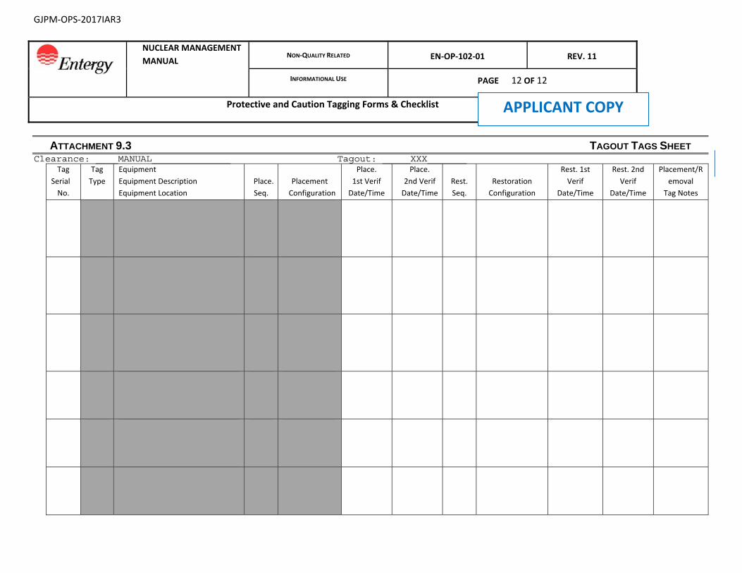
GJPM‐OPS‐2017IAR3
NUCLEAR MANAGEMENT
MANUAL NON‐QUALITY RELATED EN‐OP‐102‐01 REV. 11
INFORMATIONAL USE PAGE 12 OF 12
Protective and Caution Tagging Forms & Checklist
ATTACHMENT 9.3 TAGOUT TAGS SHEET Clearance: ____MANUAL______________ Tagout: _____XXX_______
Tag
Serial
No.
Tag
Type
Equipment
Equipment Description
Equipment Location
Place.
Seq.
Placement
Configuration
Place.
1st Verif
Date/Time
Place.
2nd Verif
Date/Time
Rest.
Seq.
Restoration
Configuration
Rest. 1st
Verif
Date/Time
Rest. 2nd
Verif
Date/Time
Placement/R
emoval
Tag Notes
APPLICANT COPY
Date of Examination: 12/04/2017
Operating Test Number: GGNS 12‐2017
Facility: Grand Gulf Nuclear Station
JPM Number: GJPM‐OPS‐2017IAR4
Rev. 01 11/06/2017 Page 1 of 15
2017I AR4
GGNS
2017 NRC Operating Test
Job Performance Measure
JPM Number: GJPM‐OPS‐2017AR4 JPM Title: Perform Emergency Notifications Facility Number: N/A _ (If Bank or Modified from Bank)
JPM Attributes:
New Modified Direct from bank
Time Critical Alternate Path Validation Time: 15 min
Prepared By: Michael Rasch 11/06/2017
Exam Developer Date
Ops Review: Robert Brinkman 11/06/2017
1st Validation by Ops Rep or Ops Validation Crew Date
Validated By: Benny White \ Chase Miller 11/06/2017
2nd Validation by Ops Validation Crew Date
Approved By: Ricky Liddell 11/06/2017
Project Lead or Exam Team Lead Date
Date of Examination: 12/04/2017
Operating Test Number: GGNS 12‐2017
Facility: Grand Gulf Nuclear Station
JPM Number: GJPM‐OPS‐2017IAR4
Rev. 01 11/06/2017 Page 2 of 15
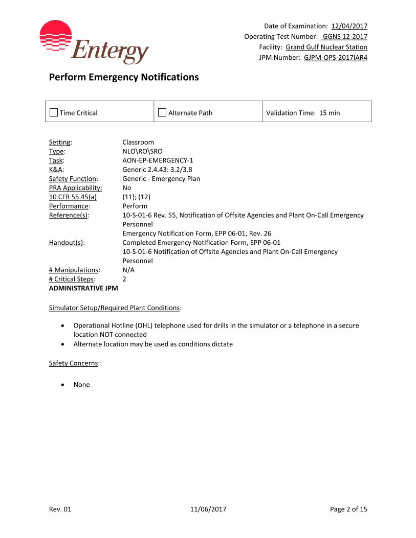
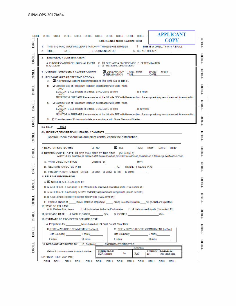
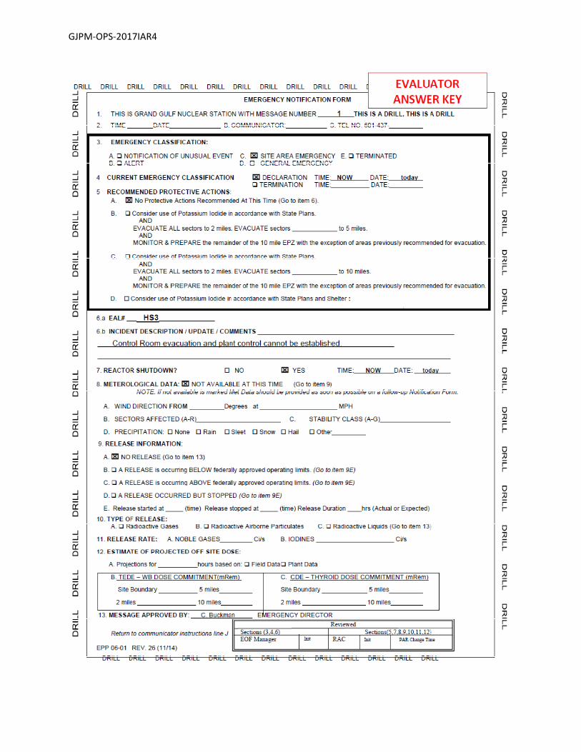
Perform Emergency Notifications
Time Critical Alternate Path Validation Time: 15 min
Setting: Classroom Type: NLO\RO\SRO Task: AON‐EP‐EMERGENCY‐1 K&A: Generic 2.4.43: 3.2/3.8 Safety Function: Generic ‐ Emergency Plan PRA Applicability: No 10 CFR 55.45(a) (11); (12) Performance: Perform Reference(s): 10‐S‐01‐6 Rev. 55, Notification of Offsite Agencies and Plant On‐Call Emergency
Personnel Emergency Notification Form, EPP 06‐01, Rev. 26 Handout(s): Completed Emergency Notification Form, EPP 06‐01 10‐S‐01‐6 Notification of Offsite Agencies and Plant On‐Call Emergency
Personnel # Manipulations: N/A # Critical Steps: 2 ADMINISTRATIVE JPM
Simulator Setup/Required Plant Conditions:
Operational Hotline (OHL) telephone used for drills in the simulator or a telephone in a secure location NOT connected
Alternate location may be used as conditions dictate
Safety Concerns:
None
Date of Examination: 12/04/2017
Operating Test Number: GGNS 12‐2017
Facility: Grand Gulf Nuclear Station
JPM Number: GJPM‐OPS‐2017IAR4
Rev. 01 11/06/2017 Page 3 of 15
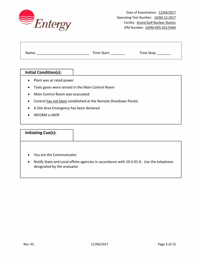
Name: ___________________________ Time Start: _______ Time Stop: _______
Initial Condition(s):
Plant was at rated power
Toxic gases were sensed in the Main Control Room
Main Control Room was evacuated
Control has not been established at the Remote Shutdown Panels
A Site Area Emergency has been declared
INFORM is INOP
Initiating Cue(s):
You are the Communicator
Notify State and Local offsite agencies in accordance with 10‐S‐01‐6. Use the telephone designated by the evaluator
Date of Examination: 12/04/2017
Operating Test Number: GGNS 12‐2017
Facility: Grand Gulf Nuclear Station
JPM Number: GJPM‐OPS‐2017IAR4
Rev. 01 11/06/2017 Page 4 of 15
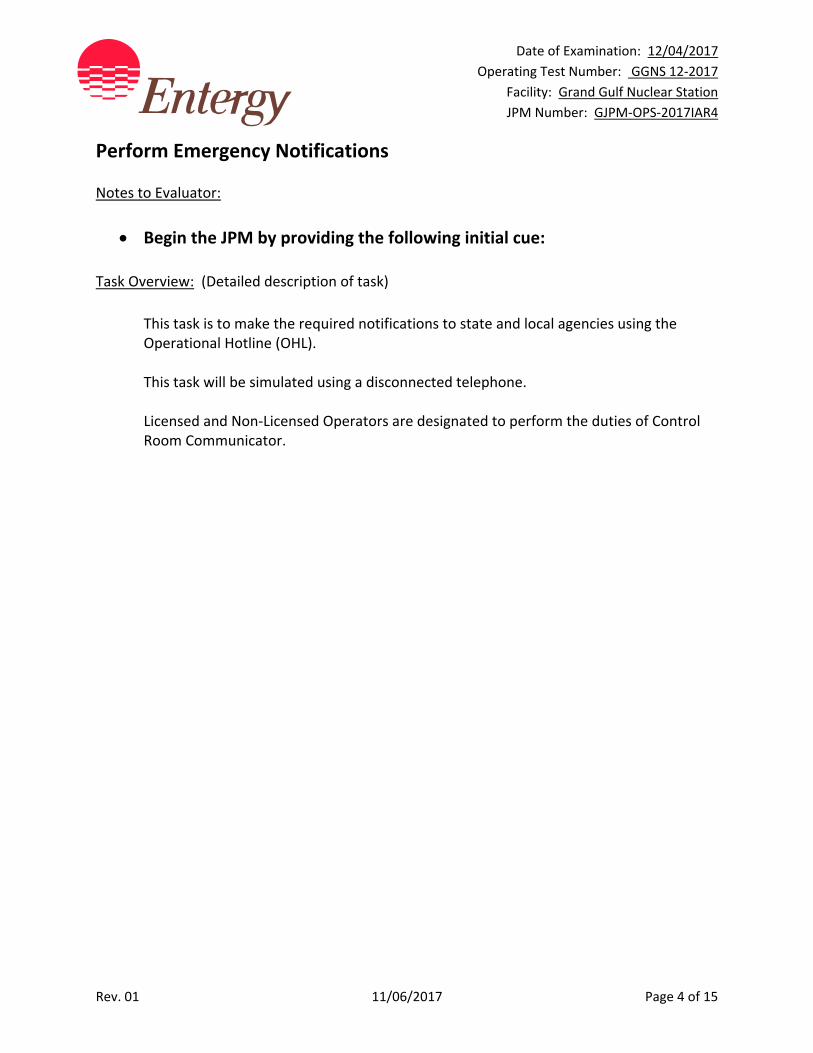
Perform Emergency Notifications Notes to Evaluator:
Begin the JPM by providing the following initial cue:
Task Overview: (Detailed description of task)
This task is to make the required notifications to state and local agencies using the Operational Hotline (OHL). This task will be simulated using a disconnected telephone. Licensed and Non‐Licensed Operators are designated to perform the duties of Control Room Communicator.
Date of Examination: 12/04/2017
Operating Test Number: GGNS 12‐2017
Facility: Grand Gulf Nuclear Station
JPM Number: GJPM‐OPS‐2017IAR4
Rev. 01 11/06/2017 Page 5 of 15
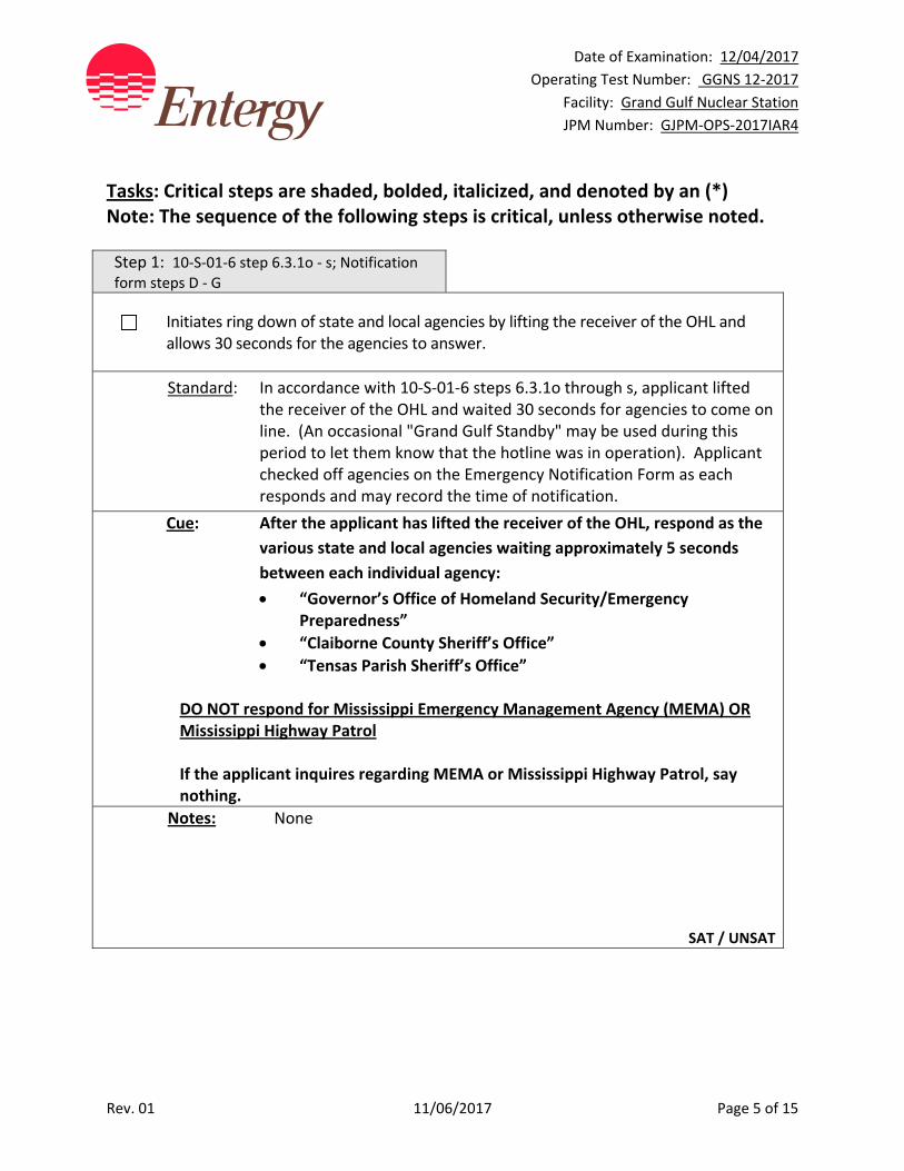
Tasks: Critical steps are shaded, bolded, italicized, and denoted by an (*) Note: The sequence of the following steps is critical, unless otherwise noted.
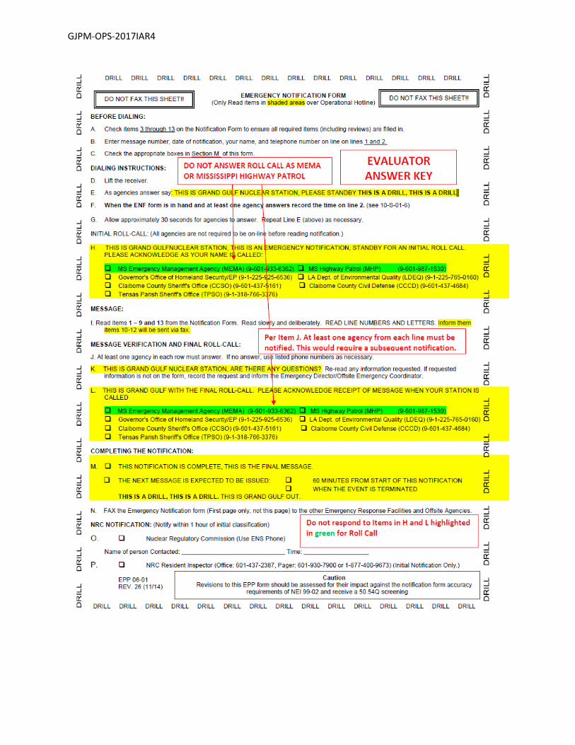
Step 1: 10‐S‐01‐6 step 6.3.1o ‐ s; Notification form steps D ‐ G
Initiates ring down of state and local agencies by lifting the receiver of the OHL and allows 30 seconds for the agencies to answer.
Standard: In accordance with 10‐S‐01‐6 steps 6.3.1o through s, applicant lifted the receiver of the OHL and waited 30 seconds for agencies to come on line. (An occasional "Grand Gulf Standby" may be used during this period to let them know that the hotline was in operation). Applicant checked off agencies on the Emergency Notification Form as each responds and may record the time of notification.
Cue: After the applicant has lifted the receiver of the OHL, respond as the
various state and local agencies waiting approximately 5 seconds
between each individual agency:
“Governor’s Office of Homeland Security/Emergency Preparedness”
“Claiborne County Sheriff’s Office”
“Tensas Parish Sheriff’s Office”
DO NOT respond for Mississippi Emergency Management Agency (MEMA) OR Mississippi Highway Patrol If the applicant inquires regarding MEMA or Mississippi Highway Patrol, say nothing.
Notes: None
SAT / UNSAT
Date of Examination: 12/04/2017
Operating Test Number: GGNS 12‐2017
Facility: Grand Gulf Nuclear Station
JPM Number: GJPM‐OPS‐2017IAR4
Rev. 01 11/06/2017 Page 6 of 15
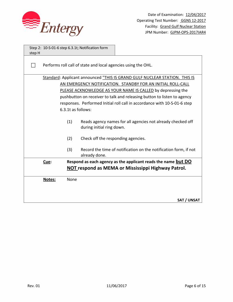
Step 2: 10‐S‐01‐6 step 6.3.1t; Notification form step H
Performs roll call of state and local agencies using the OHL.
Standard: Applicant announced "THIS IS GRAND GULF NUCLEAR STATION. THIS IS
AN EMERGENCY NOTIFICATION. STANDBY FOR AN INITIAL ROLL‐CALL
PLEASE ACKNOWLEDGE AS YOUR NAME IS CALLED by depressing the
pushbutton on receiver to talk and releasing button to listen to agency
responses. Performed Initial roll call in accordance with 10‐S‐01‐6 step
6.3.1t as follows:
(1) Reads agency names for all agencies not already checked off
during initial ring down. (2) Check off the responding agencies. (3) Record the time of notification on the notification form, if not
already done.
Cue: Respond as each agency as the applicant reads the name but DO NOT respond as MEMA or Mississippi Highway Patrol.
Notes: None
SAT / UNSAT
Date of Examination: 12/04/2017
Operating Test Number: GGNS 12‐2017
Facility: Grand Gulf Nuclear Station
JPM Number: GJPM‐OPS‐2017IAR4
Rev. 01 11/06/2017 Page 7 of 15
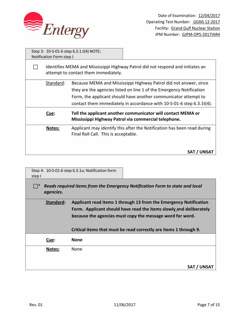
Step 3: 10‐S‐01‐6 step 6.3.1.t(4) NOTE; Notification Form step J
Identifies MEMA and Mississippi Highway Patrol did not respond and initiates an attempt to contact them immediately.
Standard: Because MEMA and Mississippi Highway Patrol did not answer, since
they are the agencies listed on line 1 of the Emergency Notification
Form, the applicant should have another communicator attempt to
contact them immediately in accordance with 10‐S‐01‐6 step 6.3.1t(4).
Cue: Tell the applicant another communicator will contact MEMA or Mississippi Highway Patrol via commercial telephone.
Notes: Applicant may identify this after the Notification has been read during Final Roll Call. This is acceptable.
SAT / UNSAT
Step 4: 10‐S‐01‐6 step 6.3.1u; Notification form step I
* Reads required items from the Emergency Notification Form to state and local agencies.
Standard: Applicant read items 1 through 13 from the Emergency Notification
Form. Applicant should have read the items slowly and deliberately
because the agencies must copy the message word for word.
Critical items that must be read correctly are items 1 through 9.
Cue: None
Notes: None
SAT / UNSAT
Date of Examination: 12/04/2017
Operating Test Number: GGNS 12‐2017
Facility: Grand Gulf Nuclear Station
JPM Number: GJPM‐OPS‐2017IAR4
Rev. 01 11/06/2017 Page 8 of 15
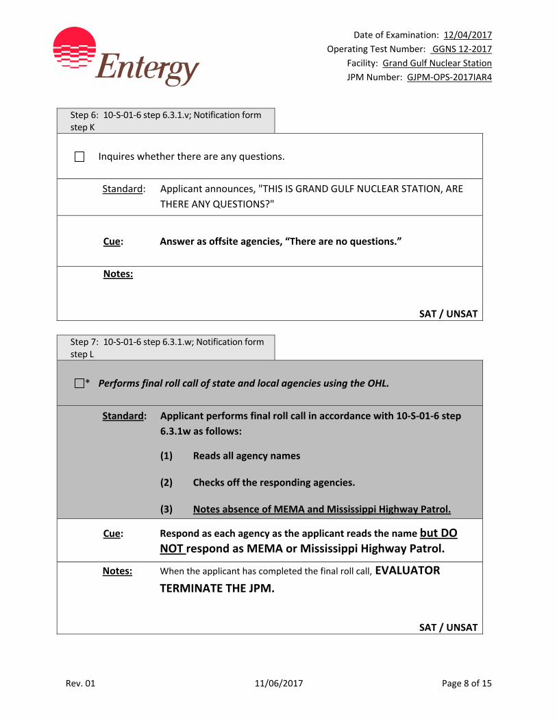
Step 6: 10‐S‐01‐6 step 6.3.1.v; Notification form step K
Inquires whether there are any questions.
Standard: Applicant announces, "THIS IS GRAND GULF NUCLEAR STATION, ARE
THERE ANY QUESTIONS?"
Cue: Answer as offsite agencies, “There are no questions.”
Notes:
SAT / UNSAT
Step 7: 10‐S‐01‐6 step 6.3.1.w; Notification form step L
* Performs final roll call of state and local agencies using the OHL.
Standard: Applicant performs final roll call in accordance with 10‐S‐01‐6 step
6.3.1w as follows:
(1) Reads all agency names (2) Checks off the responding agencies. (3) Notes absence of MEMA and Mississippi Highway Patrol.
Cue: Respond as each agency as the applicant reads the name but DO NOT respond as MEMA or Mississippi Highway Patrol.
Notes: When the applicant has completed the final roll call, EVALUATOR
TERMINATE THE JPM.
SAT / UNSAT
Date of Examination: 12/04/2017
Operating Test Number: GGNS 12‐2017
Facility: Grand Gulf Nuclear Station
JPM Number: GJPM‐OPS‐2017IAR4
Rev. 01 11/06/2017 Page 9 of 15
Task Standard(s):
Notification of the Offsite Agencies has been performed per 10‐S‐01‐6. Absence of the Mississippi Emergency Management (MEMA) and /or Mississippi Highway Patrol noted from final roll call.
SAT / UNSAT
Remember to record stop time

Date of Examination: 12/04/2017
Operating Test Number: GGNS 12‐2017
Facility: Grand Gulf Nuclear Station
JPM Number: GJPM‐OPS‐2017IAR4
Rev. 01 11/06/2017 Page 10 of 15
Follow‐Up Questions & Answers:
Comments:
GJPM‐OPS‐2017IAR4
Give this page to the applicant
Initial Condition(s):
Plant was at rated power
Toxic gases were sensed in the Main Control Room
Main Control Room was evacuated
Control has not been established at the Remote Shutdown Panels
A Site Area Emergency has been declared
INFORM is INOP
Initiating Cue(s):
You are the Communicator
Notify State and Local offsite agencies in accordance with 10‐S‐01‐6. Use the telephone designated by the evaluator
GJPM‐OPS‐2017IAR4

GJPM‐OPS‐2017IAR4
GJPM‐OPS‐2017IAR4
GJPM‐OPS‐2017IAR4

Date of Examination: 12/04/2017
Operating Test Number: GGNS 12‐2017
Facility: Grand Gulf Nuclear Station
JPM Number: GJPM‐OPS‐2017IAS1
Rev. 01 11/07/2017 Page 1 of 11
2017I AS1
GGNS
2017 NRC Operating Test
Job Performance Measure
JPM Number: GJPM‐OPS‐2017IAS1 JPM Title: Perform EOOS Risk Assessment
Facility Number: GJPM‐OPS‐AUDIT 2017AS1 (If Bank or Modified from Bank)
JPM Attributes:
New Modified Direct from bank
Time Critical Alternate Path Validation Time: 10 min
Prepared By: Michael Rasch 11/07/2017
Exam Developer Date
Ops Review: Robert Brinkman 11/07/2017
1st Validation by Ops Rep or Ops Validation Crew Date
Validated By: Billy Newman \ Gabriel Hargrove 11/07/2017
2nd Validation by Ops Validation Crew Date
Approved By: Ricky Liddell 11/07/2017
Project Lead or Exam Team Lead Date
Date of Examination: 12/04/2017
Operating Test Number: GGNS 12‐2017
Facility: Grand Gulf Nuclear Station
JPM Number: GJPM‐OPS‐2017IAS1
Rev. 01 11/07/2017 Page 2 of 11
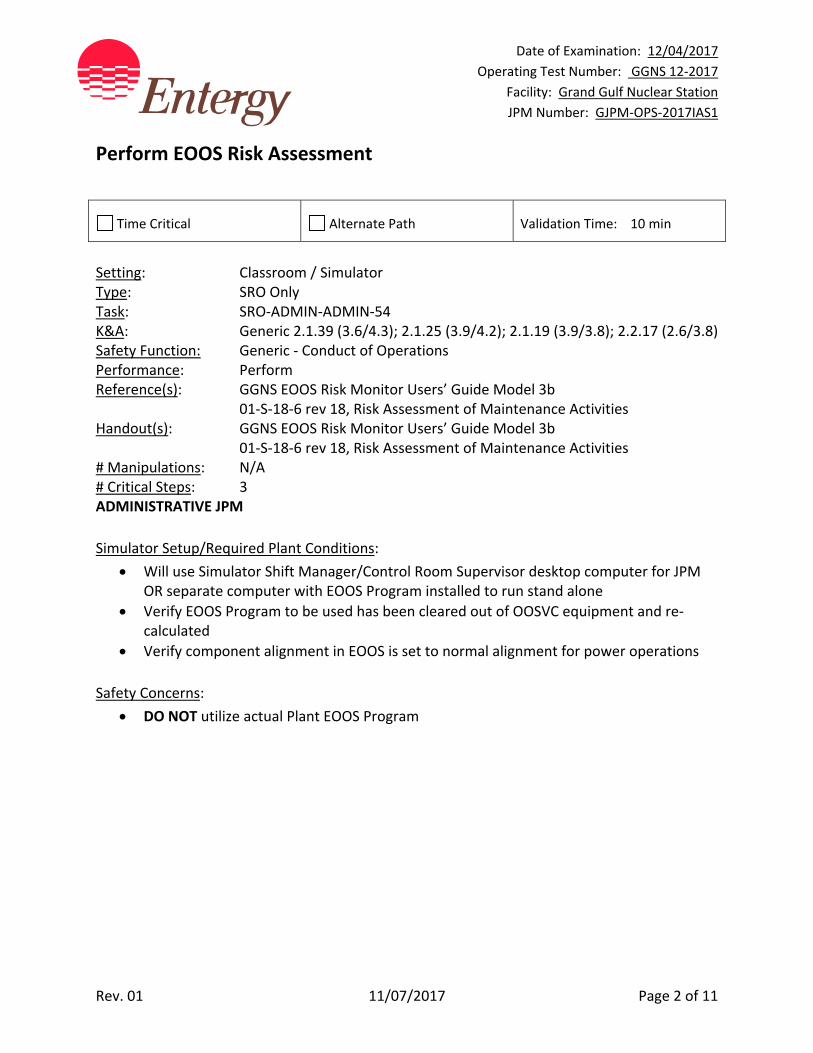
Perform EOOS Risk Assessment
Time Critical Alternate Path Validation Time: 10 min
Setting: Classroom / Simulator Type: SRO Only Task: SRO‐ADMIN‐ADMIN‐54 K&A: Generic 2.1.39 (3.6/4.3); 2.1.25 (3.9/4.2); 2.1.19 (3.9/3.8); 2.2.17 (2.6/3.8) Safety Function: Generic ‐ Conduct of Operations Performance: Perform Reference(s): GGNS EOOS Risk Monitor Users’ Guide Model 3b 01‐S‐18‐6 rev 18, Risk Assessment of Maintenance Activities Handout(s): GGNS EOOS Risk Monitor Users’ Guide Model 3b 01‐S‐18‐6 rev 18, Risk Assessment of Maintenance Activities # Manipulations: N/A # Critical Steps: 3 ADMINISTRATIVE JPM
Simulator Setup/Required Plant Conditions:
Will use Simulator Shift Manager/Control Room Supervisor desktop computer for JPM OR separate computer with EOOS Program installed to run stand alone
Verify EOOS Program to be used has been cleared out of OOSVC equipment and re‐calculated
Verify component alignment in EOOS is set to normal alignment for power operations
Safety Concerns:
DO NOT utilize actual Plant EOOS Program
Date of Examination: 12/04/2017
Operating Test Number: GGNS 12‐2017
Facility: Grand Gulf Nuclear Station
JPM Number: GJPM‐OPS‐2017IAS1
Rev. 01 11/07/2017 Page 3 of 11
Name: ___________________________ Time Start: _______ Time Stop: _______
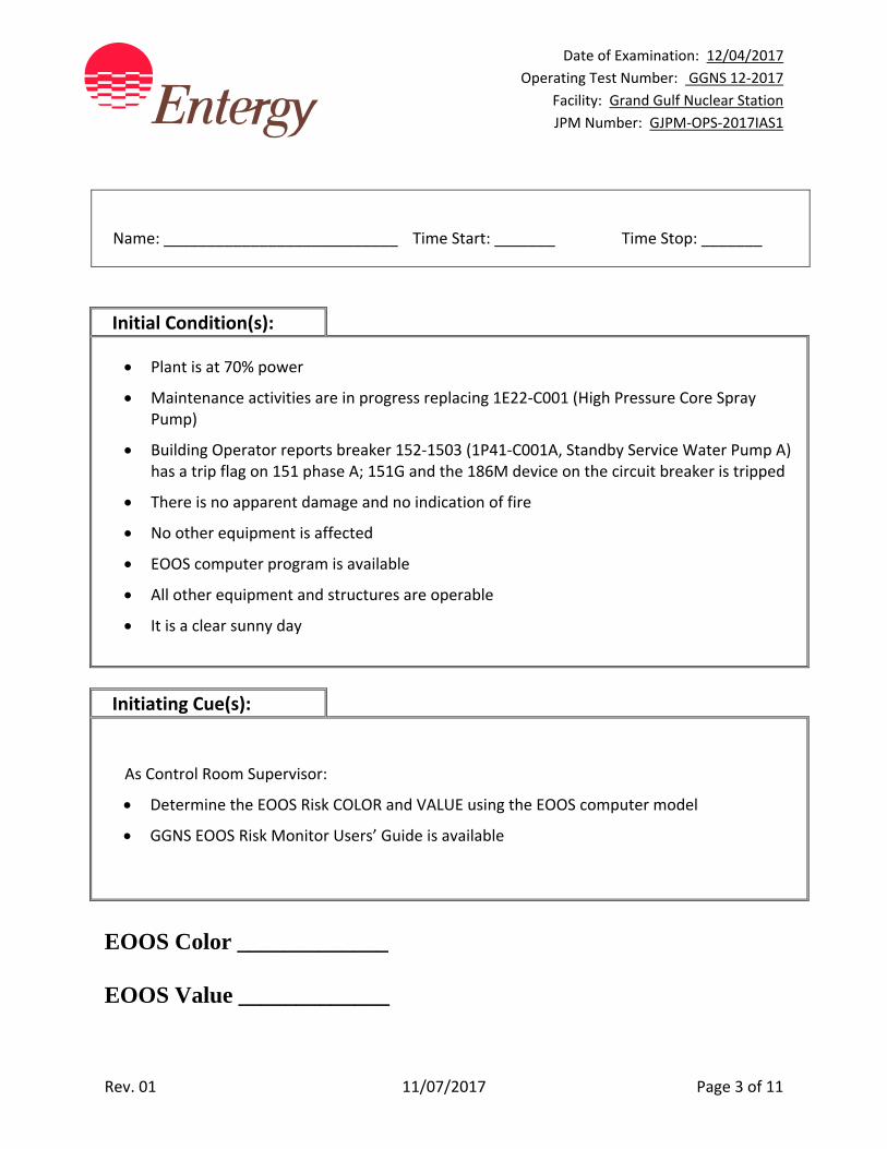
Initial Condition(s):
Plant is at 70% power
Maintenance activities are in progress replacing 1E22‐C001 (High Pressure Core Spray Pump)
Building Operator reports breaker 152‐1503 (1P41‐C001A, Standby Service Water Pump A) has a trip flag on 151 phase A; 151G and the 186M device on the circuit breaker is tripped
There is no apparent damage and no indication of fire
No other equipment is affected
EOOS computer program is available
All other equipment and structures are operable
It is a clear sunny day
Initiating Cue(s):
As Control Room Supervisor:
Determine the EOOS Risk COLOR and VALUE using the EOOS computer model
GGNS EOOS Risk Monitor Users’ Guide is available
EOOS Color _____________ EOOS Value _____________
Date of Examination: 12/04/2017
Operating Test Number: GGNS 12‐2017
Facility: Grand Gulf Nuclear Station
JPM Number: GJPM‐OPS‐2017IAS1
Rev. 01 11/07/2017 Page 4 of 11
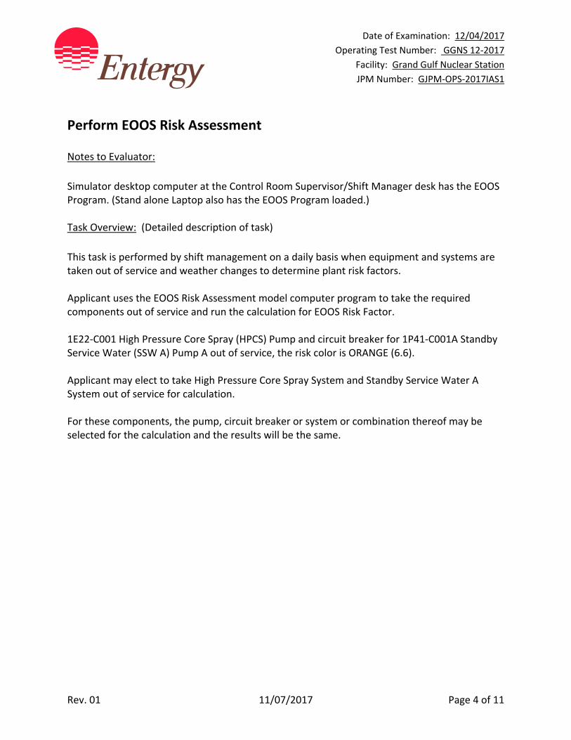
Perform EOOS Risk Assessment Notes to Evaluator:
Simulator desktop computer at the Control Room Supervisor/Shift Manager desk has the EOOS Program. (Stand alone Laptop also has the EOOS Program loaded.) Task Overview: (Detailed description of task)
This task is performed by shift management on a daily basis when equipment and systems are taken out of service and weather changes to determine plant risk factors. Applicant uses the EOOS Risk Assessment model computer program to take the required components out of service and run the calculation for EOOS Risk Factor. 1E22‐C001 High Pressure Core Spray (HPCS) Pump and circuit breaker for 1P41‐C001A Standby Service Water (SSW A) Pump A out of service, the risk color is ORANGE (6.6). Applicant may elect to take High Pressure Core Spray System and Standby Service Water A System out of service for calculation. For these components, the pump, circuit breaker or system or combination thereof may be selected for the calculation and the results will be the same.
Date of Examination: 12/04/2017
Operating Test Number: GGNS 12‐2017
Facility: Grand Gulf Nuclear Station
JPM Number: GJPM‐OPS‐2017IAS1
Rev. 01 11/07/2017 Page 5 of 11
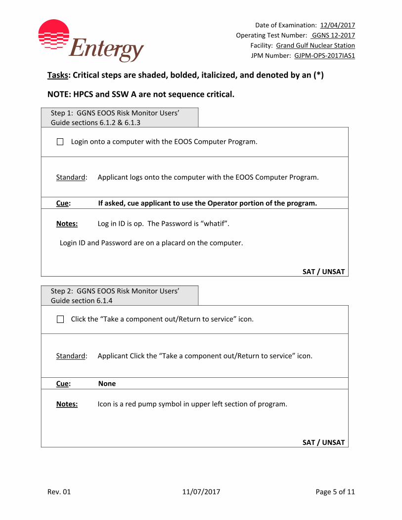
Tasks: Critical steps are shaded, bolded, italicized, and denoted by an (*)
NOTE: HPCS and SSW A are not sequence critical.
Step 1: GGNS EOOS Risk Monitor Users’ Guide sections 6.1.2 & 6.1.3
Login onto a computer with the EOOS Computer Program.
Standard: Applicant logs onto the computer with the EOOS Computer Program.
Cue: If asked, cue applicant to use the Operator portion of the program.
Notes: Log in ID is op. The Password is “whatif”. Login ID and Password are on a placard on the computer.
SAT / UNSAT
Step 2: GGNS EOOS Risk Monitor Users’ Guide section 6.1.4
Click the “Take a component out/Return to service” icon.
Standard: Applicant Click the “Take a component out/Return to service” icon.
Cue: None
Notes: Icon is a red pump symbol in upper left section of program.
SAT / UNSAT

Date of Examination: 12/04/2017
Operating Test Number: GGNS 12‐2017
Facility: Grand Gulf Nuclear Station
JPM Number: GJPM‐OPS‐2017IAS1
Rev. 01 11/07/2017 Page 6 of 11
Step 3: GGNS EOOS Risk Monitor Users’ Guide section 6.1.4
* Select the components to be taken out of service1E22‐C001 High Pressure Core
Spray Pump and click right arrow to add to Out of service list.
Standard: Applicant selects 1E22‐C001 and places in Out of service column.
Cue: None
Notes: Applicant may select HPCS System, circuit breaker 152‐1702 or pump 1E22‐
C001, any of these are acceptable.
SAT / UNSAT
Step 4: GGNS EOOS Risk Monitor Users’ Guide section 6.1.4
* Select the components to be taken out of service 1P41‐C001A Standby Service
Water Pump A and click right arrow to add to Out of service list.
Standard: Applicant selects 1P41‐C001A and places in Out of service column.
Cue: None
Notes: Applicant may select the SSW A System, circuit breaker 152‐1503 or pump
1P41‐C001A, any of these are acceptable. 152‐1503 supplies Standby Service Water Pump A
SAT / UNSAT
Date of Examination: 12/04/2017
Operating Test Number: GGNS 12‐2017
Facility: Grand Gulf Nuclear Station
JPM Number: GJPM‐OPS‐2017IAS1
Rev. 01 11/07/2017 Page 7 of 11
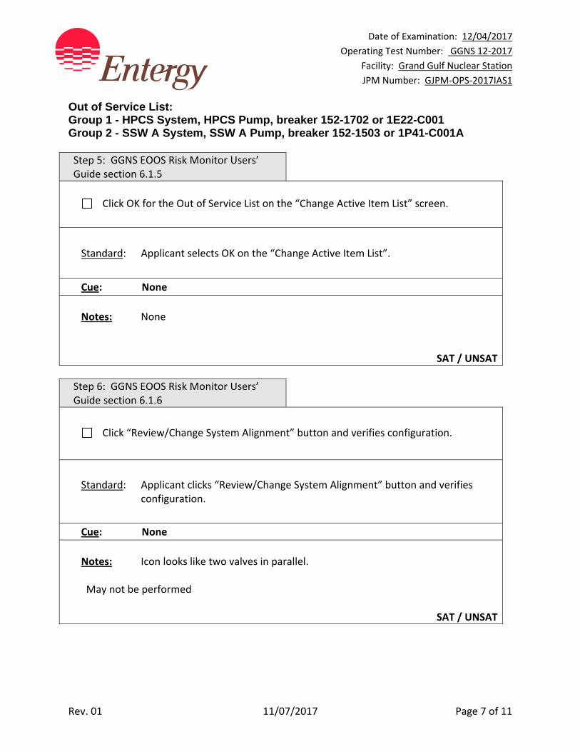
Out of Service List: Group 1 - HPCS System, HPCS Pump, breaker 152-1702 or 1E22-C001 Group 2 - SSW A System, SSW A Pump, breaker 152-1503 or 1P41-C001A Step 5: GGNS EOOS Risk Monitor Users’ Guide section 6.1.5
Click OK for the Out of Service List on the “Change Active Item List” screen.
Standard: Applicant selects OK on the “Change Active Item List”.
Cue: None
Notes: None
SAT / UNSAT
Step 6: GGNS EOOS Risk Monitor Users’ Guide section 6.1.6
Click “Review/Change System Alignment” button and verifies configuration.
Standard: Applicant clicks “Review/Change System Alignment” button and verifies configuration.
Cue: None
Notes: Icon looks like two valves in parallel. May not be performed
SAT / UNSAT
Date of Examination: 12/04/2017
Operating Test Number: GGNS 12‐2017
Facility: Grand Gulf Nuclear Station
JPM Number: GJPM‐OPS‐2017IAS1
Rev. 01 11/07/2017 Page 8 of 11
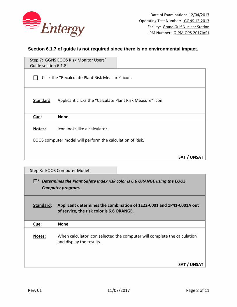
Section 6.1.7 of guide is not required since there is no environmental impact. Step 7: GGNS EOOS Risk Monitor Users’ Guide section 6.1.8
Click the “Recalculate Plant Risk Measure” icon.
Standard: Applicant clicks the “Calculate Plant Risk Measure” icon.
Cue: None
Notes: Icon looks like a calculator. EOOS computer model will perform the calculation of Risk.
SAT / UNSAT
Step 8: EOOS Computer Model
* Determines the Plant Safety Index risk color is 6.6 ORANGE using the EOOS
Computer program.
Standard: Applicant determines the combination of 1E22‐C001 and 1P41‐C001A out of service, the risk color is 6.6 ORANGE.
Cue: None
Notes: When calculator icon selected the computer will complete the calculation
and display the results.
SAT / UNSAT
Date of Examination: 12/04/2017
Operating Test Number: GGNS 12‐2017
Facility: Grand Gulf Nuclear Station
JPM Number: GJPM‐OPS‐2017IAS1
Rev. 01 11/07/2017 Page 9 of 11
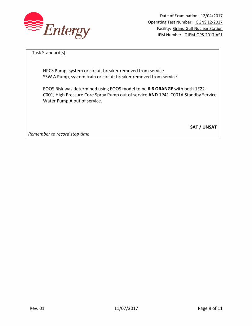
Task Standard(s):
HPCS Pump, system or circuit breaker removed from service SSW A Pump, system train or circuit breaker removed from service EOOS Risk was determined using EOOS model to be 6.6 ORANGE with both 1E22‐C001, High Pressure Core Spray Pump out of service AND 1P41‐C001A Standby Service Water Pump A out of service.
SAT / UNSAT
Remember to record stop time
Date of Examination: 12/04/2017
Operating Test Number: GGNS 12‐2017
Facility: Grand Gulf Nuclear Station
JPM Number: GJPM‐OPS‐2017IAS1
Rev. 01 11/07/2017 Page 10 of 11
Follow-Up Questions & Answers:
Comments:

GJPM‐OPS‐2017IAS1
Give this page to the applicant
Initial Condition(s):
Plant is at 70% power
Maintenance activities are in progress replacing 1E22‐C001 (High Pressure Core Spray Pump)
Building Operator reports breaker 152‐1503 (1P41‐C001A, Standby Service Water Pump A) has a trip flag on 151 phase A; 151G and the 186M device on the circuit breaker is tripped
There is no apparent damage and no indication of fire
No other equipment is affected
EOOS computer program is available
All other equipment and structures are operable
It is a clear sunny day
Initiating Cue(s):
As Control Room Supervisor:
Determine the EOOS Risk COLOR and VALUE using the EOOS computer model
GGNS EOOS Risk Monitor Users’ Guide is available
EOOS Color _____________ EOOS Value _____________
Date of Examination: 12/04/2017
Operating Test Number: GGNS 12‐2017
Facility: Grand Gulf Nuclear Station
JPM Number: GJPM‐OPS‐2017IAS2
Rev. 01 11/07/2017 Page 1 of 16
2017I AS2
GGNS
2017 NRC Operating Test
Job Performance Measure
JPM Number: GJPM‐OPS‐2017IAS2 JPM Title: Review Completed Surveillance
Facility Number: N/A (If Bank or Modified from Bank)
JPM Attributes:
New Modified Direct from bank
Time Critical Alternate Path Validation Time: 15 min
Prepared By: Michael Rasch 11/07/2017
Exam Developer Date
Ops Review: Robert Brinkman 11/07/2017
1st Validation by Ops Rep or Ops Validation Crew Date
Validated By: Billy Newman \ Gabriel Hargrove 11/07/2017
2nd Validation by Ops Validation Crew Date
Approved By: Ricky Liddell 11/07/2017
Project Lead or Exam Team Lead Date
Date of Examination: 12/04/2017
Operating Test Number: GGNS 12‐2017
Facility: Grand Gulf Nuclear Station
JPM Number: GJPM‐OPS‐2017IAS2
Rev. 01 11/07/2017 Page 2 of 16
Review Completed Surveillance
Time Critical Alternate Path Validation Time: 15 min
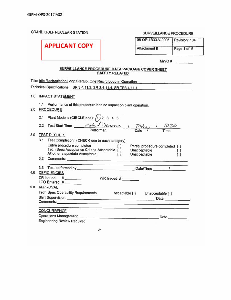
Setting: Classroom Type: SRO Only Task: SRO‐M&S‐ADMIN‐14 K&A: Generic 2.1.2 (4.4); 2.1.7 (4.7); 2.2.12 (4.1); 2.2.22 (4.7) Safety Function: Generic ‐ Conduct of Operations PRA Applicability: No 10CFR 55.45(a) (1); (12); (13) Performance: Perform Reference(s): 06‐OP‐1B33‐V‐0005 Rev. 104, Idle Recirculation Loop Startup Surveillance 01‐S‐06‐12 Rev. 112, Surveillance Program Procedure Handout(s): Completed Applicant copy 06‐OP‐1B33‐V‐0005, Attachment II and IV Calculator # Manipulations: N/A # Critical Steps: 1 ADMINISTRATIVE JPM
Simulator Setup/Required Plant Conditions:
None
Safety Concerns:
None
Date of Examination: 12/04/2017
Operating Test Number: GGNS 12‐2017
Facility: Grand Gulf Nuclear Station
JPM Number: GJPM‐OPS‐2017IAS2
Rev. 01 11/07/2017 Page 3 of 16
Name: ___________________________ Time Start: _______ Time Stop: _______
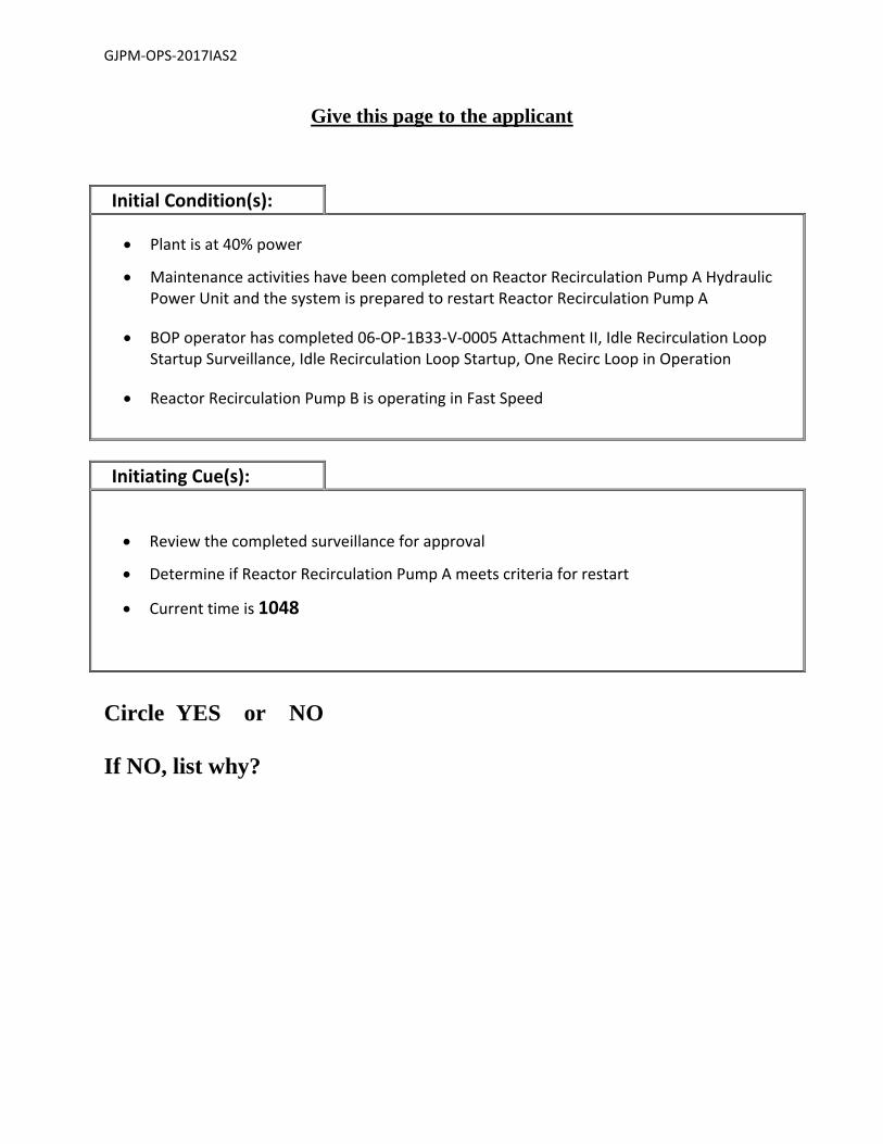
Initial Condition(s):
Plant is at 40% power
Maintenance activities have been completed on Reactor Recirculation Pump A Hydraulic Power Unit and the system is prepared to restart Reactor Recirculation Pump A
BOP operator has completed 06‐OP‐1B33‐V‐0005 Attachment II, Idle Recirculation Loop Startup Surveillance, Idle Recirculation Loop Startup, One Recirc Loop in Operation
Reactor Recirculation Pump B is operating in Fast Speed
Initiating Cue(s):
Review the completed surveillance for approval
Determine if Reactor Recirculation Pump A meets criteria for restart
Current time is 1048
Date of Examination: 12/04/2017
Operating Test Number: GGNS 12‐2017
Facility: Grand Gulf Nuclear Station
JPM Number: GJPM‐OPS‐2017IAS2
Rev. 01 11/07/2017 Page 4 of 16
Review Completed Surveillance Notes to Evaluator:
Applicant will have completed 06‐OP‐1B33‐V‐0005 Attachment II Data Sheets I and II for Reactor Recirculation Loop A startup. Task Overview: (Detailed description of task)
This task is performed to meet surveillance requirements for idle Reactor Recirculation Pump startup at various power levels. Senior Reactor Operators (Operations Shift Management) authorize and review completed surveillances to allow startup of idle Reactor Recirculation pumps.

Date of Examination: 12/04/2017
Operating Test Number: GGNS 12‐2017
Facility: Grand Gulf Nuclear Station
JPM Number: GJPM‐OPS‐2017IAS2
Rev. 01 11/07/2017 Page 5 of 16
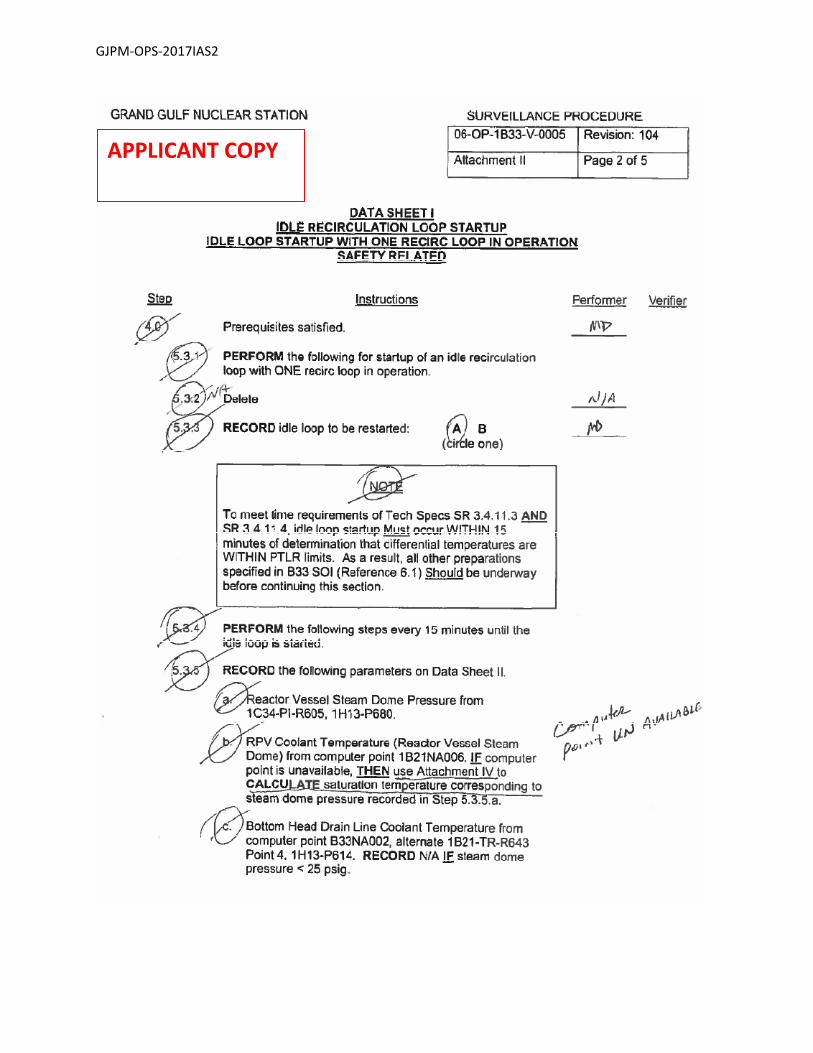
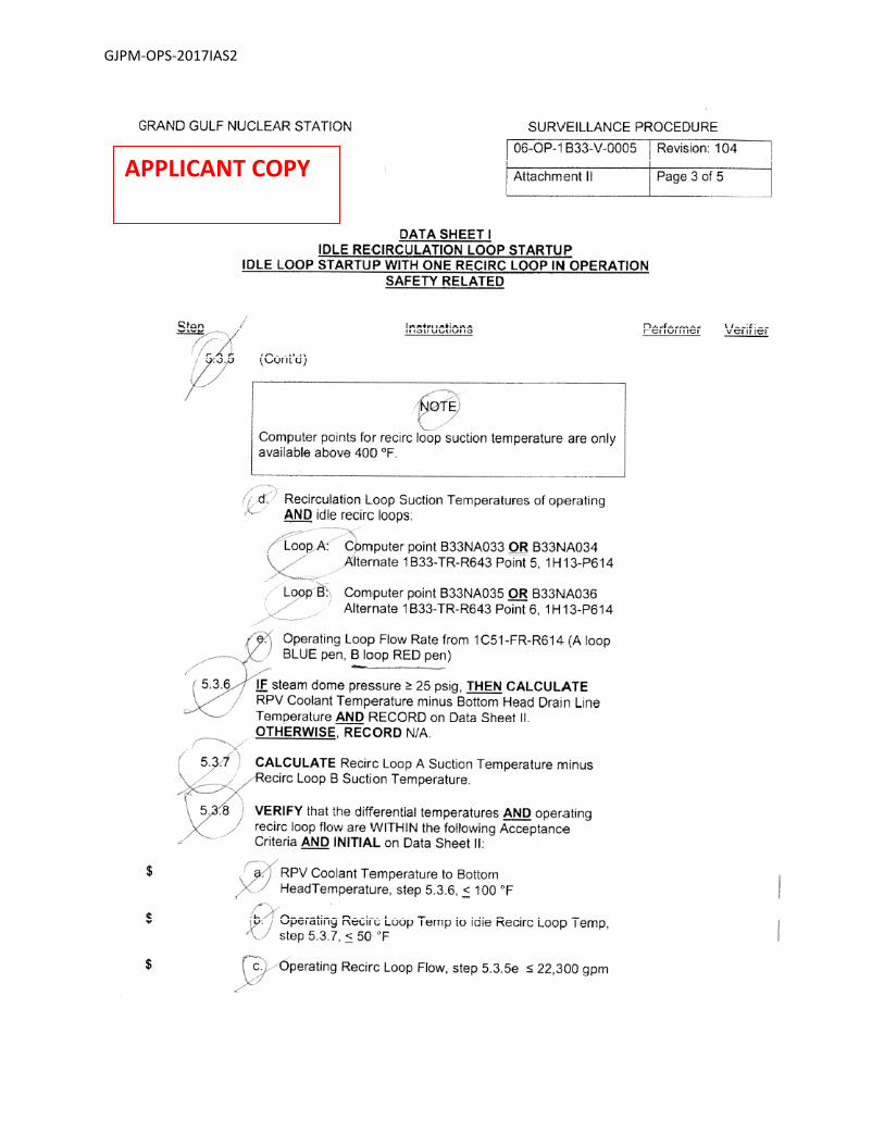
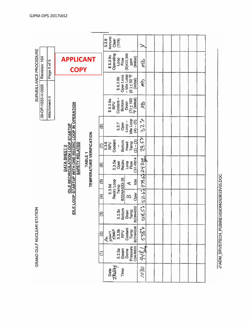
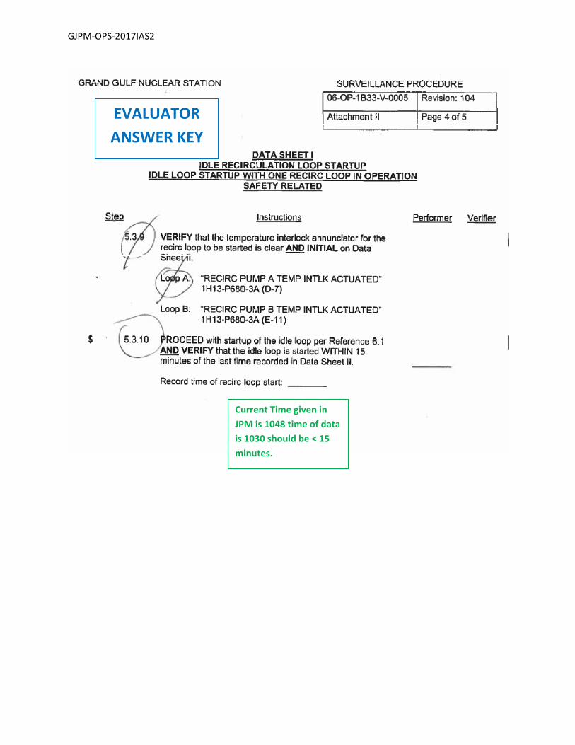
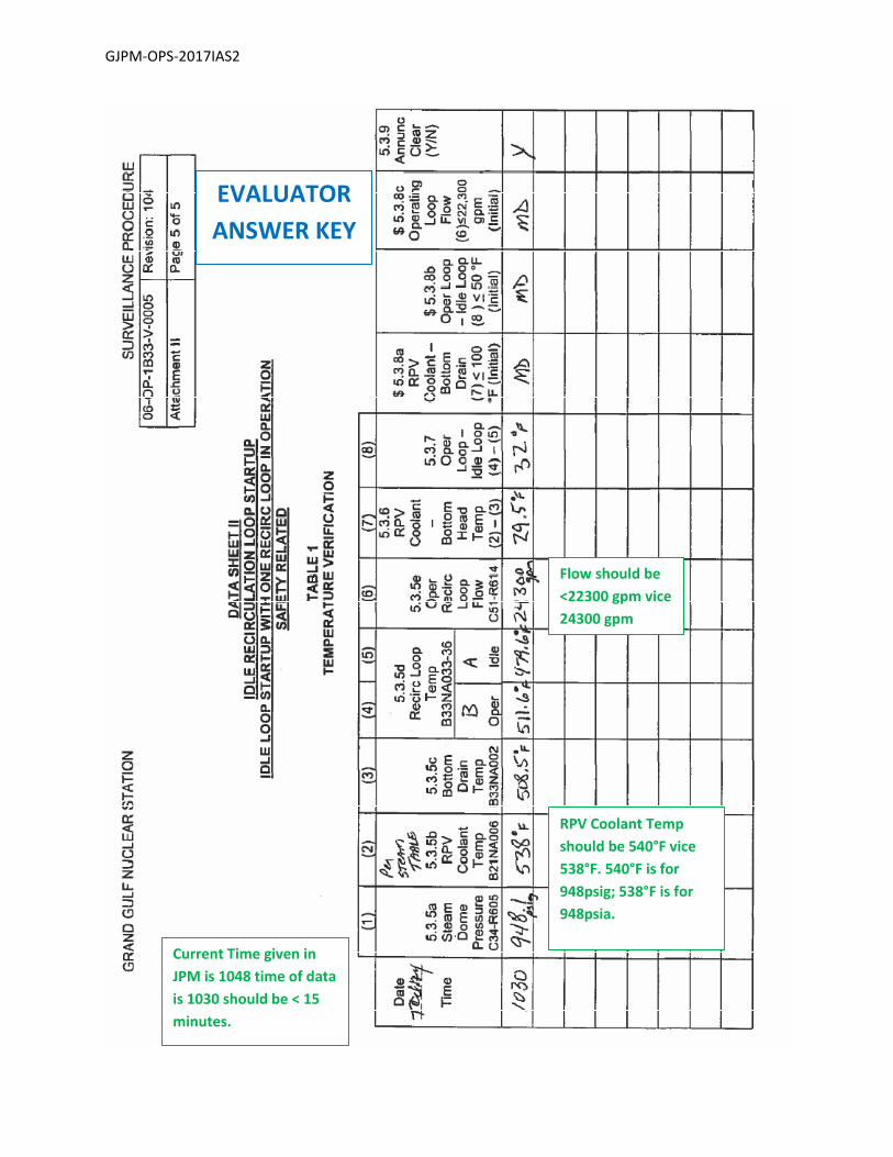
Tasks: Critical steps are shaded, bolded, italicized, and denoted by an (*) Note: The sequence of the following is NOT critical. Step 1: 06‐OP‐1B33‐V‐0005 Attachment II and 01‐S‐06‐12 section 5.8
* Review completed surveillance 06‐OP‐1B33‐V‐0005 Attachment II Data Sheets I and
II.
Standard: Applicant reviews data on surveillance Data Sheets and determines the following:
RPV Coolant temperature calculation from Steam Table is incorrect Value on surveillance is 538 degrees F should be 540 degrees F Operating Loop flow is above the flow rate value listed. Value should be < 22300 gpm vice 24300 gpm Elapsed time has exceeded the time from the last readings by greater
than 15 minutes Time of data 1030 current time 1048 > 15 minutes
Cue: None
Notes: The incorrect calculation of the RPV Coolant Temperature will alter the true
number for the calculation of RPV Coolant Temperature to Bottom Head Temperature.
Applicant must identify two of the three discrepancies for satisfactory completion of the JPM.
SAT / UNSAT
Date of Examination: 12/04/2017
Operating Test Number: GGNS 12‐2017
Facility: Grand Gulf Nuclear Station
JPM Number: GJPM‐OPS‐2017IAS2
Rev. 01 11/07/2017 Page 6 of 16
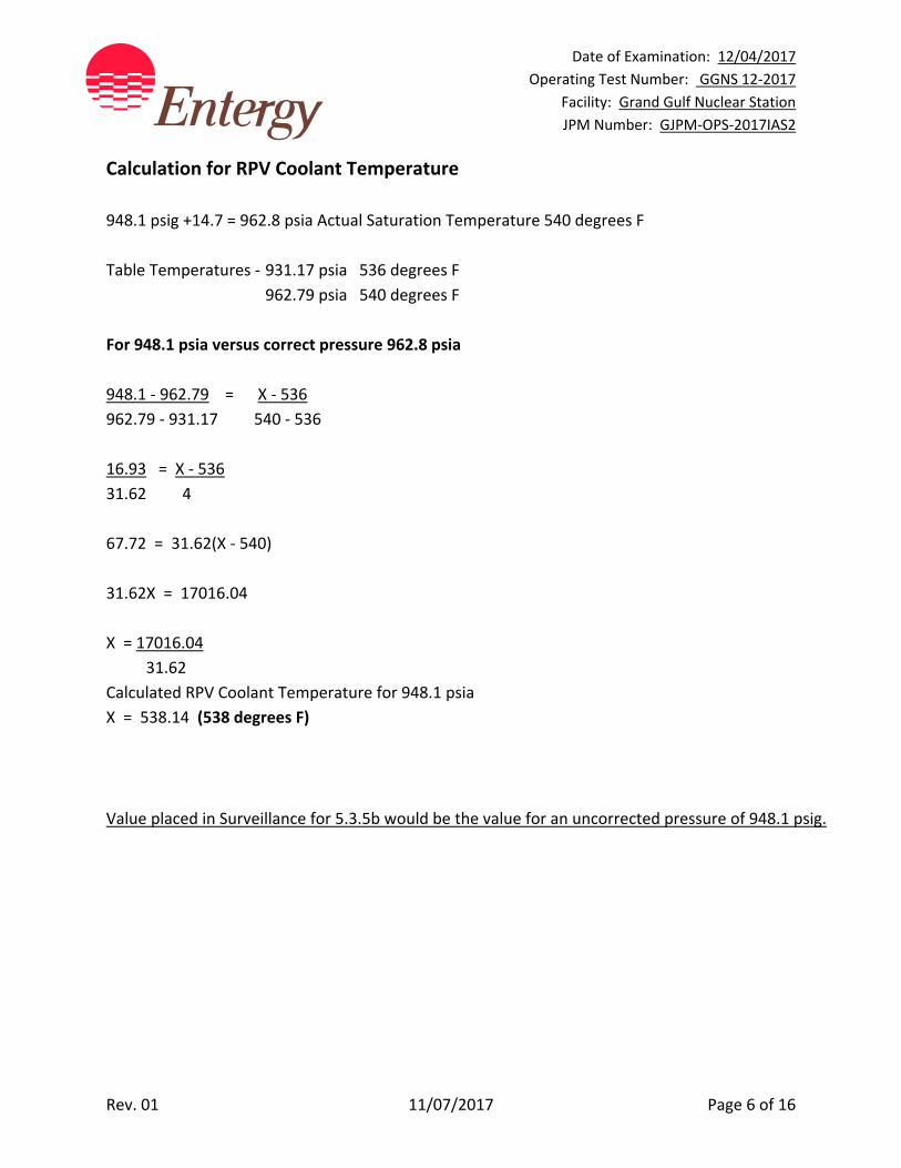
Calculation for RPV Coolant Temperature
948.1 psig +14.7 = 962.8 psia Actual Saturation Temperature 540 degrees F
Table Temperatures ‐ 931.17 psia 536 degrees F
962.79 psia 540 degrees F
For 948.1 psia versus correct pressure 962.8 psia
948.1 ‐ 962.79 = X ‐ 536
962.79 ‐ 931.17 540 ‐ 536
16.93 = X ‐ 536
31.62 4
67.72 = 31.62(X ‐ 540)
31.62X = 17016.04
X = 17016.04
31.62
Calculated RPV Coolant Temperature for 948.1 psia
X = 538.14 (538 degrees F)
Value placed in Surveillance for 5.3.5b would be the value for an uncorrected pressure of 948.1 psig.
Date of Examination: 12/04/2017
Operating Test Number: GGNS 12‐2017
Facility: Grand Gulf Nuclear Station
JPM Number: GJPM‐OPS‐2017IAS2
Rev. 01 11/07/2017 Page 7 of 16
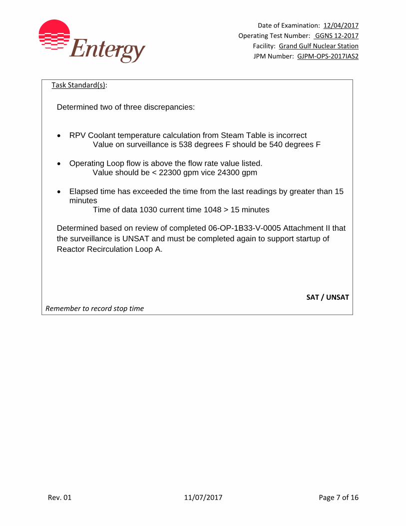
Task Standard(s):
Determined two of three discrepancies:
RPV Coolant temperature calculation from Steam Table is incorrect Value on surveillance is 538 degrees F should be 540 degrees F
Operating Loop flow is above the flow rate value listed.
Value should be < 22300 gpm vice 24300 gpm Elapsed time has exceeded the time from the last readings by greater than 15
minutes Time of data 1030 current time 1048 > 15 minutes
Determined based on review of completed 06-OP-1B33-V-0005 Attachment II that the surveillance is UNSAT and must be completed again to support startup of Reactor Recirculation Loop A.
SAT / UNSAT
Remember to record stop time

Date of Examination: 12/04/2017
Operating Test Number: GGNS 12‐2017
Facility: Grand Gulf Nuclear Station
JPM Number: GJPM‐OPS‐2017IAS2
Rev. 01 11/07/2017 Page 8 of 16
Follow-Up Questions & Answers:
Comments:
GJPM‐OPS‐2017IAS2
Give this page to the applicant
Initial Condition(s):
Plant is at 40% power
Maintenance activities have been completed on Reactor Recirculation Pump A Hydraulic Power Unit and the system is prepared to restart Reactor Recirculation Pump A
BOP operator has completed 06‐OP‐1B33‐V‐0005 Attachment II, Idle Recirculation Loop Startup Surveillance, Idle Recirculation Loop Startup, One Recirc Loop in Operation
Reactor Recirculation Pump B is operating in Fast Speed
Initiating Cue(s):
Review the completed surveillance for approval
Determine if Reactor Recirculation Pump A meets criteria for restart
Current time is 1048
Circle YES or NO If NO, list why?
GJPM‐OPS‐2017IAS2
APPLICANT COPY
GJPM‐OPS‐2017IAS2
APPLICANT COPY
GJPM‐OPS‐2017IAS2
APPLICANT COPY

GJPM‐OPS‐2017IAS2
APPLICANT COPY
GJPM‐OPS‐2017IAS2
APPLICANT
COPY
GJPM‐OPS‐2017IAS2
EVALUATOR
ANSWER KEY
Current Time given in
JPM is 1048 time of data
is 1030 should be < 15
minutes.
GJPM‐OPS‐2017IAS2
EVALUATOR
ANSWER KEY
RPV Coolant Temp
should be 540°F vice
538°F. 540°F is for
948psig; 538°F is for
948psia.
Flow should be
<22300 gpm vice
24300 gpm
Current Time given in
JPM is 1048 time of data
is 1030 should be < 15
minutes.
Date of Examination: 12/04/2017
Operating Test Number: GGNS 12‐2017
Facility: Grand Gulf Nuclear Station
JPM Number: GJPM‐OPS‐2017IAS3
Rev. 01 11/07/2017 Page 1 of 12
2017I AS3
GGNS
2017 NRC Operating Test
Job Performance Measure
JPM Number: GJPM‐OPS‐2017IAS3 JPM Title: Determine Impact on Plant
Operations for Failed Relay
Facility Number: _GJPM‐SRO‐2017AS33_ (If Bank or Modified from Bank)
JPM Attributes:
New Modified Direct from bank
Time Critical Alternate Path Validation Time: 15 min
Prepared By: Michael Rasch 11/07/2017
Exam Developer Date
Ops Review: Robert Brinkman 11/07/2017
1st Validation by Ops Rep or Ops Validation Crew Date
Validated By: Billy Newman \ Gabe Hargrove 11/07/2017
2nd Validation by Ops Validation Crew Date
Approved By: Ricky Liddell 11/07/2017
Project Lead or Exam Team Lead Date
Date of Examination: 12/04/2017
Operating Test Number: GGNS 12‐2017
Facility: Grand Gulf Nuclear Station
JPM Number: GJPM‐OPS‐2017IAS3
Rev. 01 11/07/2017 Page 2 of 12
Determine Impact on Plant Operations for Failed Relay
Time Critical Alternate Path Validation Time: 15 Min
Setting: Classroom Type: SRO Only Task: SRO‐NO‐NORMAL‐015 K&A: Generic 2.2.41 (3.9); 2.2.22 (4.7); 2.2.36 (4.2) Safety Function: Generic ‐ Equipment Control PRA Applicability: No 10CFR 55.45(a) (12) Performance: Perform Reference(s): 04‐1‐01‐E12‐1 SU, Rev. 147 17‐S‐06‐5, Rev. 11, Tech Spec Loop Logic GGNS Technical Specifications 3.3.6.3 & 3.6.1.7 E1181‐063; 067 additionally 026; 037; 041; 043 Handout(s): 04‐1‐01‐E12‐1 SU 17‐S‐06‐5, Tech Spec Loop Logic GGNS Electrical Drawings GGNS Technical Specifications # Manipulations: N/A # Critical Steps: 2 ADMINISTRATIVE JPM Previous 2 NRC Exams May 2017 SRO Upgrade randomly selected
Simulator Setup/Required Plant Conditions:
None
Safety Concerns:
None
Date of Examination: 12/04/2017
Operating Test Number: GGNS 12‐2017
Facility: Grand Gulf Nuclear Station
JPM Number: GJPM‐OPS‐2017IAS3
Rev. 01 11/07/2017 Page 3 of 12
Name: ___________________________ Time Start: _______ Time Stop: _______
Initial Condition(s):
• Plant is operating at rated conditions
• Electrical Maintenance has reported relay 1E12‐K93A has a burned up coil (failed)
• No replacement relay is available for 48 hours
Initiating Cue(s):
As Control Room Supervisor
Determine the primary impact of the failure on plant operations
Identify any associated Technical Specification/TRM impact
Date of Examination: 12/04/2017
Operating Test Number: GGNS 12‐2017
Facility: Grand Gulf Nuclear Station
JPM Number: GJPM‐OPS‐2017IAS3
Rev. 01 11/07/2017 Page 4 of 12
Determine Impact on Plant Operations for Failed Relay Notes to Evaluator:
This is an Administrative JPM and can be performed in a classroom.
Task Overview: (Detailed description of task)
This task is to use facility electrical drawings to determine the effects a failed relay will have on the plant and its associated systems. This is a required skill for an SRO. SROs use this skill in troubleshooting plant problems, determining proper plant operation, and assessing how a problem affects facility compliance with Tech Specs. This is an activity performed on a routine basis by SROs during Agastat relay replacement.
Date of Examination: 12/04/2017
Operating Test Number: GGNS 12‐2017
Facility: Grand Gulf Nuclear Station
JPM Number: GJPM‐OPS‐2017IAS3
Rev. 01 11/07/2017 Page 5 of 12
Critical steps are shaded, bolded, italicized, and denoted by an (*)
NOTE: The sequence of the following steps is not critical unless otherwise noted.
Applicant may elect to use the Technical Specification Instrumentation Loop Logic 17‐S‐06‐5.
Residual Heat Removal System (E12) System Operating Instructions 04‐1‐01‐E12‐1 SU
References identify the Electrical Drawings as E‐1181.
Step 1: E‐1181 Electrical Drawings for E12 System
Locate the Relay Tabulation Print. (E‐1181‐063).
Standard: Relay Tabulation Print located.
Cue: None
Notes: E‐1181‐00 is the Index print for the set of drawings.
E‐1181 ‐ 063 (GE sheet 2) coordinates F‐4
Applicant may reference other drawings than those listed that is acceptable.
SAT / UNSAT
Date of Examination: 12/04/2017
Operating Test Number: GGNS 12‐2017
Facility: Grand Gulf Nuclear Station
JPM Number: GJPM‐OPS‐2017IAS3
Rev. 01 11/07/2017 Page 6 of 12
Step 2: E‐1181 Electrical Drawings for E12
System
Identify which print E12‐K93A is located on E‐1181‐063 (GE sheet 3)
Standard: E12‐K93A relay located on drawing table.
Cue: None
Notes:
Relay tabulation lists relays associated with the system and identifies the print the
relay and associated contacts are located on.
SAT / UNSAT
Date of Examination: 12/04/2017
Operating Test Number: GGNS 12‐2017
Facility: Grand Gulf Nuclear Station
JPM Number: GJPM‐OPS‐2017IAS3
Rev. 01 11/07/2017 Page 7 of 12
Step 3: E‐1181 Electrical Drawings for E12
System
Identify other affected components associated with E12‐K93A.
Standard: E12‐K95A and E12‐K30A relays are associated with E12‐K93A and are located on
E‐1181 ‐067 (GE sheet 6).
Cue: None
Notes:
E12‐K95A is the timer relay associated with E12‐F048A RHR A Heat Exchanger Bypass Valve
which keeps E12‐F048A open for a time delay following a LOCA signal.
Relay E12‐K95A (4 minutes) eliminates the 10.85 minute time delay for closing E12‐F048A.
SAT / UNSAT
Date of Examination: 12/04/2017
Operating Test Number: GGNS 12‐2017
Facility: Grand Gulf Nuclear Station
JPM Number: GJPM‐OPS‐2017IAS3
Rev. 01 11/07/2017 Page 8 of 12
Step 4: E‐1181 Electrical Drawings for E12
System
* Identify the following affects of E12‐K93A remaining de‐energized (E‐1181‐067, GE
sheet 6)
E12‐K93A is the 10.85 minute timer for Containment Spray Automatic Initiation. E12‐
K93A energizes to initiate Containment Spray. The relay being failed will prevent
automatic initiation of RHR A in Containment Spray mode.
Standard: E12‐K93A failed will prevent RHR A Containment Spray from Automatically
initiating after 10.85 minutes.
Cue: None
Notes:
May be performed by looking at 17‐S‐06‐5, Att. II, page 41 of 81
SAT / UNSAT
Date of Examination: 12/04/2017
Operating Test Number: GGNS 12‐2017
Facility: Grand Gulf Nuclear Station
JPM Number: GJPM‐OPS‐2017IAS3
Rev. 01 11/07/2017 Page 9 of 12
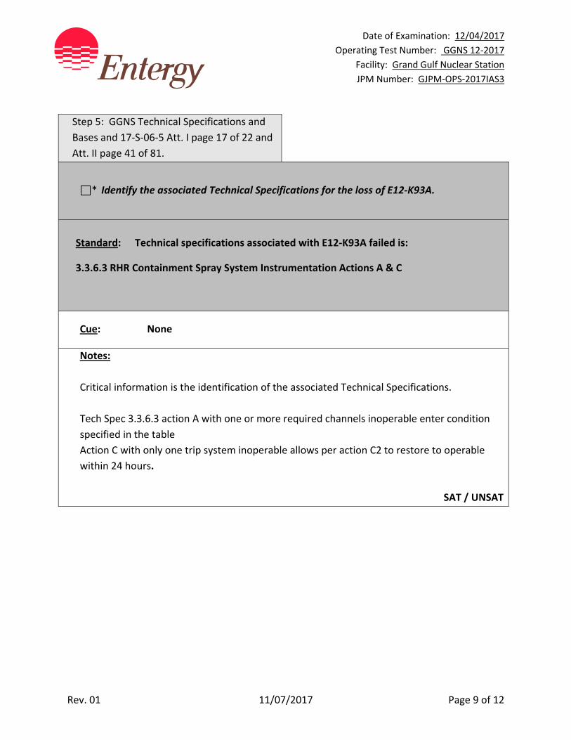
Step 5: GGNS Technical Specifications and
Bases and 17‐S‐06‐5 Att. I page 17 of 22 and
Att. II page 41 of 81.
* Identify the associated Technical Specifications for the loss of E12‐K93A.
Standard: Technical specifications associated with E12‐K93A failed is:
3.3.6.3 RHR Containment Spray System Instrumentation Actions A & C
Cue: None
Notes:
Critical information is the identification of the associated Technical Specifications.
Tech Spec 3.3.6.3 action A with one or more required channels inoperable enter condition
specified in the table
Action C with only one trip system inoperable allows per action C2 to restore to operable
within 24 hours.
SAT / UNSAT
Date of Examination: 12/04/2017
Operating Test Number: GGNS 12‐2017
Facility: Grand Gulf Nuclear Station
JPM Number: GJPM‐OPS‐2017IAS3
Rev. 01 11/07/2017 Page 10 of 12
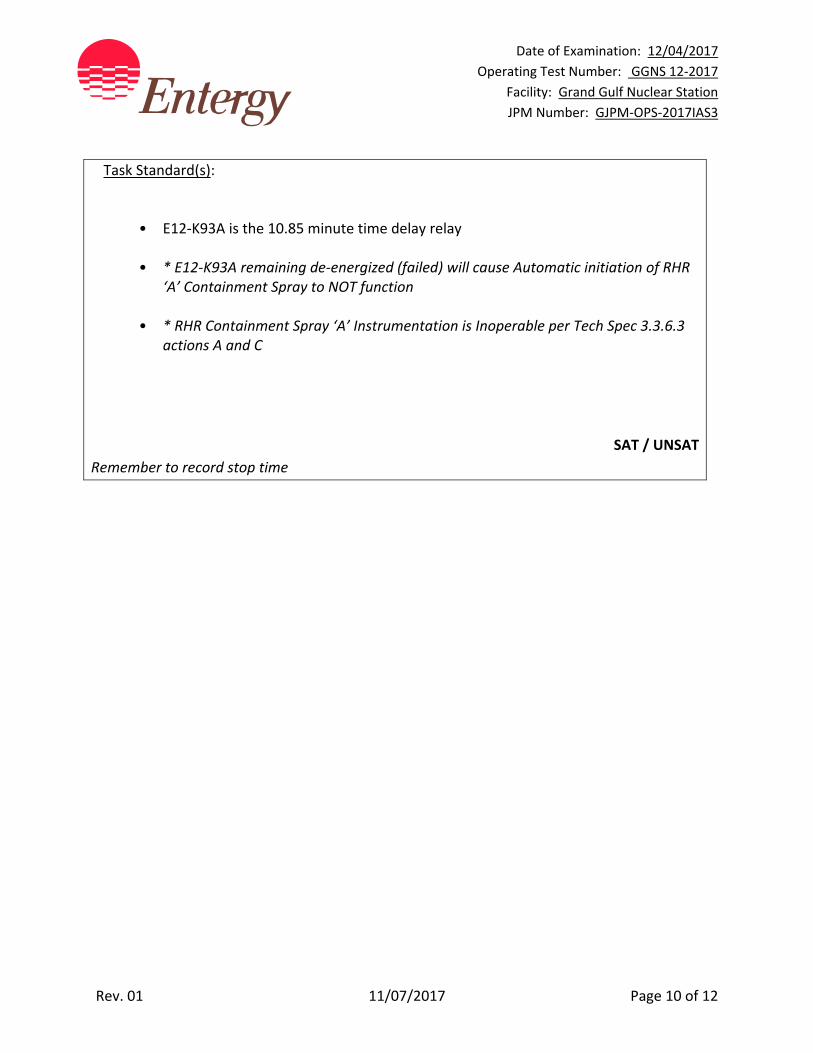
Task Standard(s):
• E12‐K93A is the 10.85 minute time delay relay
• * E12‐K93A remaining de‐energized (failed) will cause Automatic initiation of RHR ‘A’ Containment Spray to NOT function
• * RHR Containment Spray ‘A’ Instrumentation is Inoperable per Tech Spec 3.3.6.3 actions A and C
SAT / UNSAT
Remember to record stop time
Date of Examination: 12/04/2017
Operating Test Number: GGNS 12‐2017
Facility: Grand Gulf Nuclear Station
JPM Number: GJPM‐OPS‐2017IAS3
Rev. 01 11/07/2017 Page 11 of 12
Follow-Up Questions & Answers:
Comments:
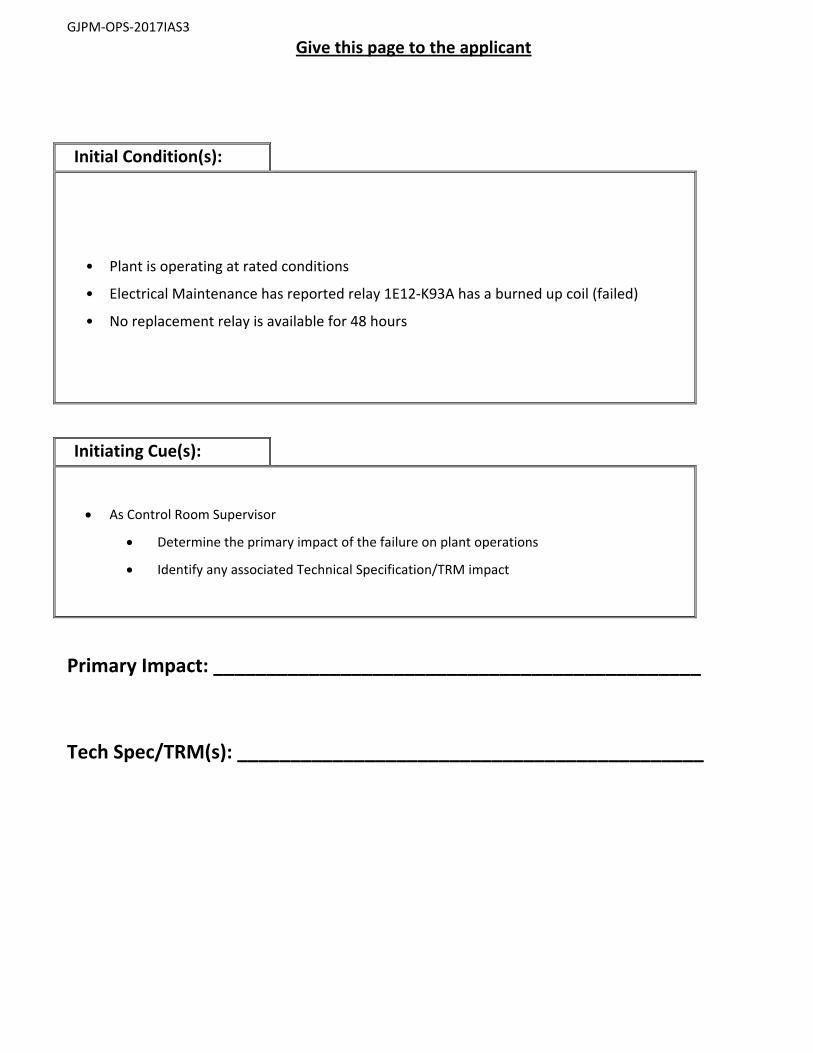
GJPM‐OPS‐2017IAS3
Give this page to the applicant
Initial Condition(s):
• Plant is operating at rated conditions
• Electrical Maintenance has reported relay 1E12‐K93A has a burned up coil (failed)
• No replacement relay is available for 48 hours
Initiating Cue(s):
As Control Room Supervisor
Determine the primary impact of the failure on plant operations
Identify any associated Technical Specification/TRM impact
Primary Impact: ______________________________________________
Tech Spec/TRM(s): ____________________________________________

Date of Examination: 12/04/2017
Operating Test Number: GGNS 12‐2017
Facility: Grand Gulf Nuclear Station
JPM Number: GJPM‐OPS‐2017IAS4
Rev. 01 11/07/2017 Page 1 of 10
2017I AS4
GGNS
2017 NRC Operating Test
Job Performance Measure
JPM Number: GJPM-OPS-2017IAS4 JPM Title: Authorize Emergency Exposure Facility Number: __GJPM-OPS-AUDIT2017AS4_ (If Bank or Modified from Bank)
JPM Attributes:
New Modified Direct from bank
Time Critical Alternate Path Validation Time: 15 min
Prepared By: Michael Rasch 11/07/2017 Exam Developer Date
Ops Review: Robert Brinkman 11/07/2017 1st Validation by Ops Rep or Ops Validation Crew Date
Validated By: Billy Newman \ Gabriel Hargrove 11/07/2017 2nd Validation by Ops Validation Crew Date
Approved By: Ricky Liddell 11/07/2017 Project Lead or Exam Team Lead Date

Date of Examination: 12/04/2017
Operating Test Number: GGNS 12‐2017
Facility: Grand Gulf Nuclear Station
JPM Number: GJPM‐OPS‐2017IAS4
Rev. 01 11/07/2017 Page 2 of 10
Authorize Emergency Exposure
Time Critical Alternate Path Validation Time: 15 Min
Setting: Classroom Type: SRO Only Task: SRO-A&E-EMERGENCY-022 K&A: Generic 2.3.4 (3.7) Safety Function: Generic - Radiation Control PRA Applicability: No 10CFR 55.45(a) (10); (11) Performance: Perform Reference(s): 10-S-01-17, Rev 19, Emergency Personnel Exposure Control EN-RP-201, Rev 5, Dosimetry Administration Handout(s): 10-S-01-17 EN-RP-201 Calculator # Manipulations: N/A # Critical Steps: 4 ADMINISTRATIVE JPM Simulator Setup/Required Plant Conditions:
o None
Safety Concerns:
o None
Date of Examination: 12/04/2017
Operating Test Number: GGNS 12‐2017
Facility: Grand Gulf Nuclear Station
JPM Number: GJPM‐OPS‐2017IAS4
Rev. 01 11/07/2017 Page 3 of 10
Name: _________________________ Time Start: _______ Time Stop: _______
Initial Condition(s):
Site Area Emergency has been declared
General area dose rate on elevation 161 ft. Containment is 6,000 mR/hr
Containment entry is required to manually open Suppression Pool Makeup Valves to protect the fuel
Task expected to take approximately 45 minutes to complete
Two qualified operators are available and required
Operator #1 current year-to-date exposure TEDE of 400 mrem Operator #2 current year-to-date exposure TEDE of 530 mrem
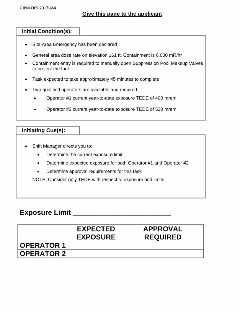
Initiating Cue(s):
Shift Manager directs you to:
Determine the current exposure limit
Determine expected exposure for both Operator #1 and Operator #2
Determine approval requirements for this task
NOTE: Consider only TEDE with respect to exposure and limits
Date of Examination: 12/04/2017
Operating Test Number: GGNS 12‐2017
Facility: Grand Gulf Nuclear Station
JPM Number: GJPM‐OPS‐2017IAS4
Rev. 01 11/07/2017 Page 4 of 10
Authorize Emergency Exposure Notes to Evaluator:
This is an Administrative JPM and can be performed in a classroom.
Task Overview: (Detailed description of task)
Applicant will evaluate a condition involving abnormally high radiological conditions and determine actions required to administratively control the dose received by determining who authorizes dose extensions in various situations.
Date of Examination: 12/04/2017
Operating Test Number: GGNS 12‐2017
Facility: Grand Gulf Nuclear Station
JPM Number: GJPM‐OPS‐2017IAS4
Rev. 01 11/07/2017 Page 5 of 10
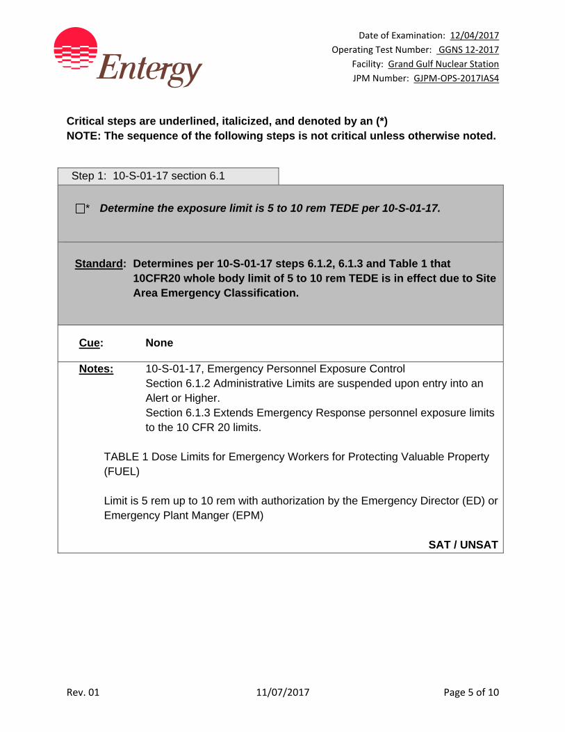
Critical steps are underlined, italicized, and denoted by an (*) NOTE: The sequence of the following steps is not critical unless otherwise noted.
Step 1: 10-S-01-17 section 6.1
* Determine the exposure limit is 5 to 10 rem TEDE per 10-S-01-17.
Standard: Determines per 10-S-01-17 steps 6.1.2, 6.1.3 and Table 1 that
10CFR20 whole body limit of 5 to 10 rem TEDE is in effect due to Site Area Emergency Classification.
Cue: None
Notes: 10-S-01-17, Emergency Personnel Exposure Control Section 6.1.2 Administrative Limits are suspended upon entry into an
Alert or Higher. Section 6.1.3 Extends Emergency Response personnel exposure limits
to the 10 CFR 20 limits.
TABLE 1 Dose Limits for Emergency Workers for Protecting Valuable Property (FUEL) Limit is 5 rem up to 10 rem with authorization by the Emergency Director (ED) or Emergency Plant Manger (EPM)
SAT / UNSAT
Date of Examination: 12/04/2017
Operating Test Number: GGNS 12‐2017
Facility: Grand Gulf Nuclear Station
JPM Number: GJPM‐OPS‐2017IAS4
Rev. 01 11/07/2017 Page 6 of 10
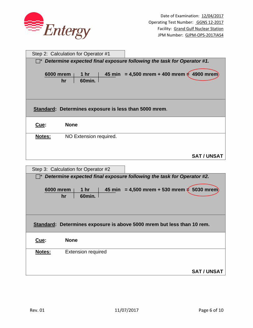
Step 2: Calculation for Operator #1
* Determine expected final exposure following the task for Operator #1. 6000 mrem 1 hr 45 min = 4,500 mrem + 400 mrem = 4900 mrem
hr 60min.
Standard: Determines exposure is less than 5000 mrem.
Cue: None
Notes: NO Extension required.
SAT / UNSAT
Step 3: Calculation for Operator #2
* Determine expected final exposure following the task for Operator #2. 6000 mrem 1 hr 45 min = 4,500 mrem + 530 mrem = 5030 mrem
hr 60min.
Standard: Determines exposure is above 5000 mrem but less than 10 rem.
Cue: None
Notes: Extension required
SAT / UNSAT
Date of Examination: 12/04/2017
Operating Test Number: GGNS 12‐2017
Facility: Grand Gulf Nuclear Station
JPM Number: GJPM‐OPS‐2017IAS4
Rev. 01 11/07/2017 Page 7 of 10
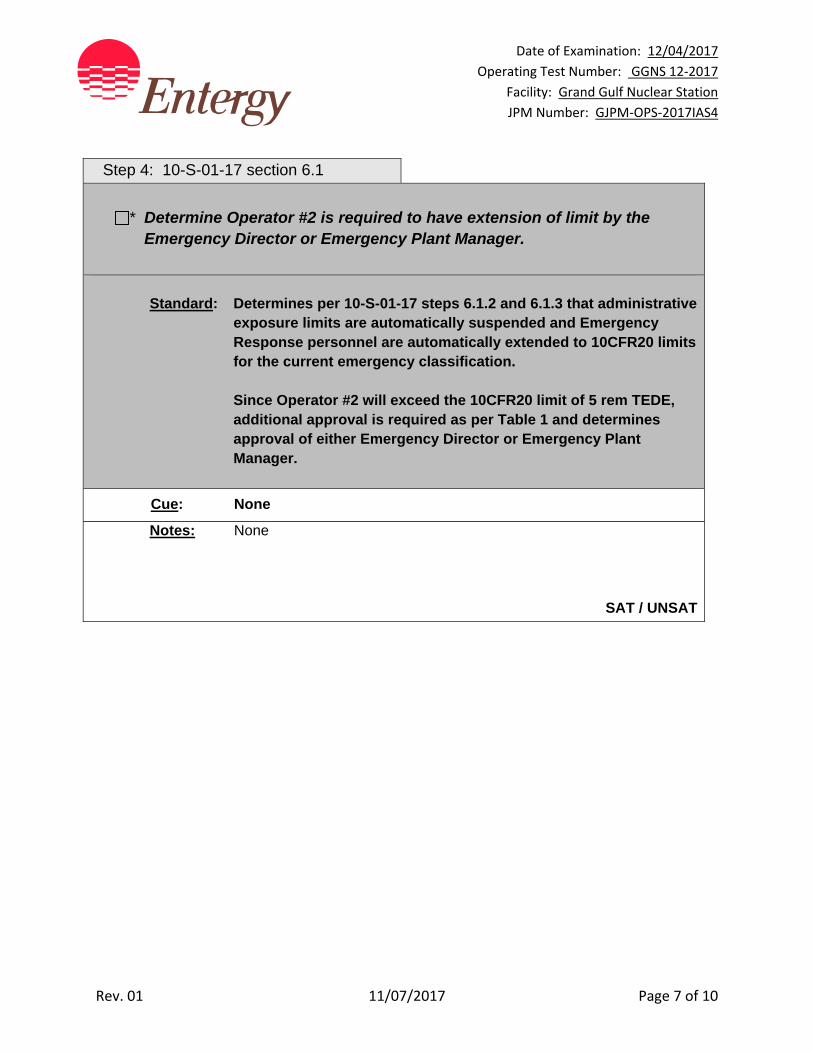
Step 4: 10-S-01-17 section 6.1
* Determine Operator #2 is required to have extension of limit by the Emergency Director or Emergency Plant Manager.
Standard: Determines per 10-S-01-17 steps 6.1.2 and 6.1.3 that administrative
exposure limits are automatically suspended and Emergency Response personnel are automatically extended to 10CFR20 limits for the current emergency classification.
Since Operator #2 will exceed the 10CFR20 limit of 5 rem TEDE, additional approval is required as per Table 1 and determines approval of either Emergency Director or Emergency Plant Manager.
Cue: None
Notes: None
SAT / UNSAT
Date of Examination: 12/04/2017
Operating Test Number: GGNS 12‐2017
Facility: Grand Gulf Nuclear Station
JPM Number: GJPM‐OPS‐2017IAS4
Rev. 01 11/07/2017 Page 8 of 10
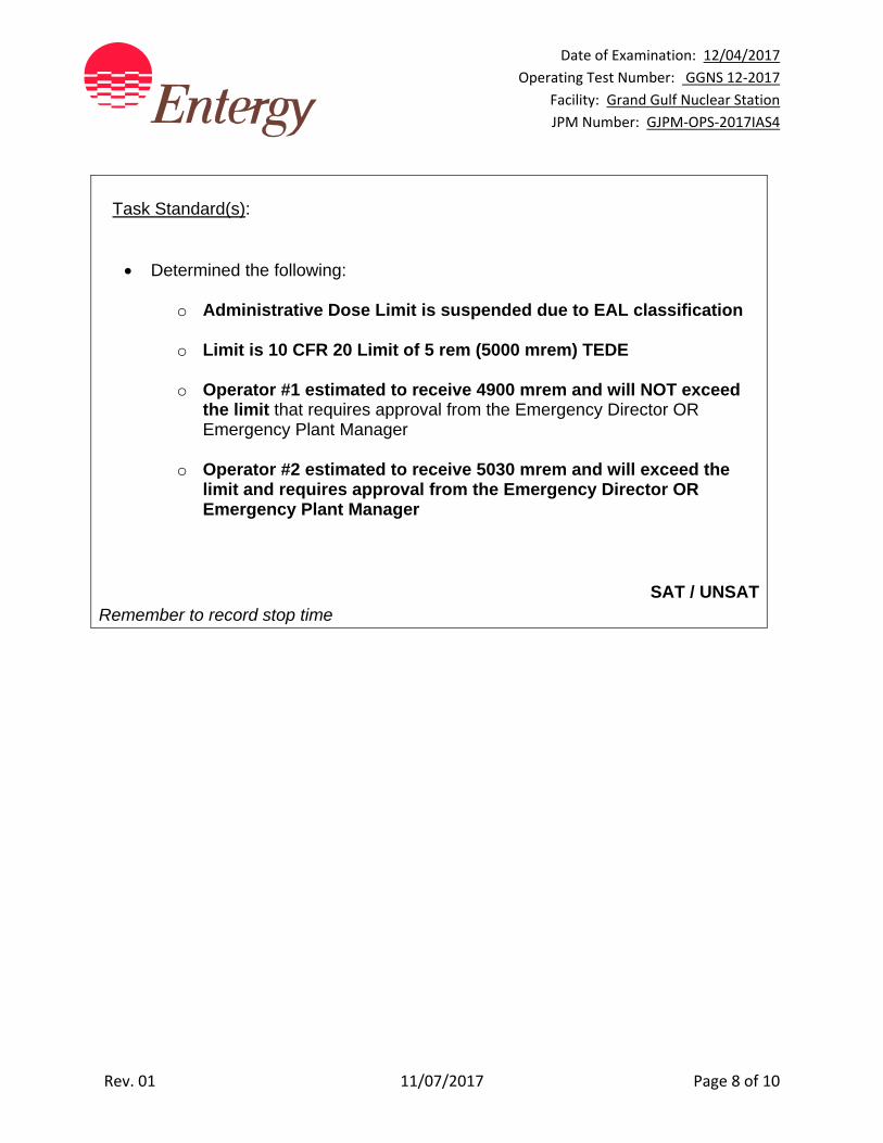
Task Standard(s):
Determined the following:
o Administrative Dose Limit is suspended due to EAL classification
o Limit is 10 CFR 20 Limit of 5 rem (5000 mrem) TEDE
o Operator #1 estimated to receive 4900 mrem and will NOT exceed the limit that requires approval from the Emergency Director OR Emergency Plant Manager
o Operator #2 estimated to receive 5030 mrem and will exceed the limit and requires approval from the Emergency Director OR Emergency Plant Manager
SAT / UNSAT
Remember to record stop time
Date of Examination: 12/04/2017
Operating Test Number: GGNS 12‐2017
Facility: Grand Gulf Nuclear Station
JPM Number: GJPM‐OPS‐2017IAS4
Rev. 01 11/07/2017 Page 9 of 10
Follow-Up Questions & Answers:
Comments:
GJPM‐OPS‐2017IAS4
Give this page to the applicant
Initial Condition(s):
Site Area Emergency has been declared
General area dose rate on elevation 161 ft. Containment is 6,000 mR/hr
Containment entry is required to manually open Suppression Pool Makeup Valves to protect the fuel
Task expected to take approximately 45 minutes to complete
Two qualified operators are available and required
Operator #1 current year-to-date exposure TEDE of 400 mrem Operator #2 current year-to-date exposure TEDE of 530 mrem
Initiating Cue(s):
Shift Manager directs you to:
Determine the current exposure limit
Determine expected exposure for both Operator #1 and Operator #2
Determine approval requirements for this task
NOTE: Consider only TEDE with respect to exposure and limits
Exposure Limit _________________________
EXPECTED EXPOSURE
APPROVAL REQUIRED
OPERATOR 1 OPERATOR 2
Date of Examination: 12/04/2017
Operating Test Number: GGNS 12‐2017
Facility: Grand Gulf Nuclear Station
JPM Number: GJPM‐OPS‐2017IAS5
Rev. 01 11/07/2017 Page 1 of 8
2017I AS5
GGNS
2017 NRC Operating Test
Job Performance Measure
JPM Number: GJPM‐OPS‐2017IAS5 JPM Title: Perform Emergency Classification
Facility Number: _______ N/A ___ (If Bank or Modified from Bank)
JPM Attributes:
New Modified Direct from bank
Time Critical 15 min Alternate Path Validation Time: 10 min
Prepared By: Michael Rasch 11/07/2017
Exam Developer Date
Ops Review: Robert Brinkman 11/07/2017
1st Validation by Ops Rep or Ops Validation Crew Date
Validated By: Billy Newman \ Gabriel Hargrove 11/07/2017
2nd Validation by Ops Validation Crew Date
Approved By: Ricky Liddell 11/07/2017
Project Lead or Exam Team Lead Date
Date of Examination: 12/04/2017
Operating Test Number: GGNS 12‐2017
Facility: Grand Gulf Nuclear Station
JPM Number: GJPM‐OPS‐2017IAS5
Rev. 01 11/07/2017 Page 2 of 8
Perform Emergency Classification
Time Critical 15 min Alternate Path Validation Time: 10 min
Setting: Classroom Type: SRO Only Task: SRO‐A&E‐EMERGENCY‐15 K&A: Generic 2.4.41 (4.6) Safety Function: Generic ‐ Emergency Procedures/Plan PRA Applicability: No 10CFR 55.45(a): (11); (12) Performance: Perform Reference(s): 10‐S‐01‐1 Revision 126, Activation of the Emergency Plan 05‐1‐02‐II‐12, Rev. 12, Toxic Spill Response 05‐1‐02‐II‐1, Rev. 49, Shutdown from Remote Shutdown Panel Handout(s): EAL flow charts from 10‐S‐01‐1 10‐S‐01‐1 (available) 05‐1‐02‐II‐12 05‐1‐02‐II‐1 # Manipulations: N/A # Critical Steps: 1
ADMINISTRATIVE JPM
Simulator Setup/Required Plant Conditions:
None
Safety Concerns:
None
Date of Examination: 12/04/2017
Operating Test Number: GGNS 12‐2017
Facility: Grand Gulf Nuclear Station
JPM Number: GJPM‐OPS‐2017IAS5
Rev. 01 11/07/2017 Page 3 of 8
Name: ___________________________ Time Start: _______ Time Stop: _______
Initial Condition(s):
Plant was operating at rated power
At 1055, workers spilled a toxic substance which caused the Main Control Room atmosphere to become hazardous
At 1056, Shift Manager decided to shutdown the Reactor and evacuate the Main Control Room
Control Room personnel obtained SCBAs and evacuated the Main Control Room
Personnel are attempting to establish control of the plant at the Remote Shutdown Panels
Initiating Cue(s):
At 1106, Remote Shutdown Panel operator informs you that control will not be established for at least 10 minutes
Classify the event
JPM is TIME CRITICAL
Date of Examination: 12/04/2017
Operating Test Number: GGNS 12‐2017
Facility: Grand Gulf Nuclear Station
JPM Number: GJPM‐OPS‐2017IAS5
Rev. 01 11/07/2017 Page 4 of 8
Perform Emergency Classification Notes to Evaluator:
None Task Overview: (Detailed description of task)
If a transient occurs or events in progress a Senior Reactor Operator must classify events as an Emergency Director in accordance with the Emergency Preparedness Plan. 10‐S‐01‐1 requires classification based on conditions of EAL HS3 Site Area Emergency. Emergency classification declaration must be completed within 15 minutes of recognition of an emergency. This task is Time Critical based on 10CFR 50 Appendix E part IV. C.2 requirements.
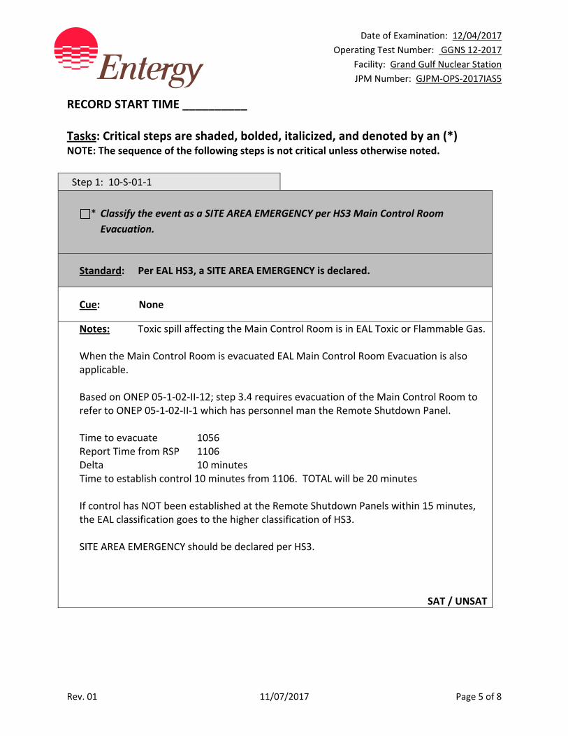
Date of Examination: 12/04/2017
Operating Test Number: GGNS 12‐2017
Facility: Grand Gulf Nuclear Station
JPM Number: GJPM‐OPS‐2017IAS5
Rev. 01 11/07/2017 Page 5 of 8
RECORD START TIME __________ Tasks: Critical steps are shaded, bolded, italicized, and denoted by an (*) NOTE: The sequence of the following steps is not critical unless otherwise noted. Step 1: 10‐S‐01‐1
* Classify the event as a SITE AREA EMERGENCY per HS3 Main Control Room
Evacuation.
Standard: Per EAL HS3, a SITE AREA EMERGENCY is declared.
Cue: None
Notes: Toxic spill affecting the Main Control Room is in EAL Toxic or Flammable Gas. When the Main Control Room is evacuated EAL Main Control Room Evacuation is also applicable. Based on ONEP 05‐1‐02‐II‐12; step 3.4 requires evacuation of the Main Control Room to refer to ONEP 05‐1‐02‐II‐1 which has personnel man the Remote Shutdown Panel. Time to evacuate 1056 Report Time from RSP 1106 Delta 10 minutes Time to establish control 10 minutes from 1106. TOTAL will be 20 minutes If control has NOT been established at the Remote Shutdown Panels within 15 minutes, the EAL classification goes to the higher classification of HS3. SITE AREA EMERGENCY should be declared per HS3.
SAT / UNSAT
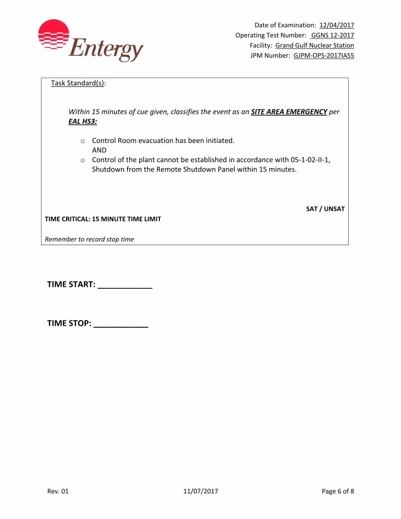
Date of Examination: 12/04/2017
Operating Test Number: GGNS 12‐2017
Facility: Grand Gulf Nuclear Station
JPM Number: GJPM‐OPS‐2017IAS5
Rev. 01 11/07/2017 Page 6 of 8
Task Standard(s):
Within 15 minutes of cue given, classifies the event as an SITE AREA EMERGENCY per EAL HS3:
o Control Room evacuation has been initiated. AND
o Control of the plant cannot be established in accordance with 05‐1‐02‐II‐1, Shutdown from the Remote Shutdown Panel within 15 minutes.
SAT / UNSAT
TIME CRITICAL: 15 MINUTE TIME LIMIT
Remember to record stop time
TIME START: ____________
TIME STOP: ____________

Date of Examination: 12/04/2017
Operating Test Number: GGNS 12‐2017
Facility: Grand Gulf Nuclear Station
JPM Number: GJPM‐OPS‐2017IAS5
Rev. 01 11/07/2017 Page 7 of 8
Follow‐Up Questions & Answers:
Comments:
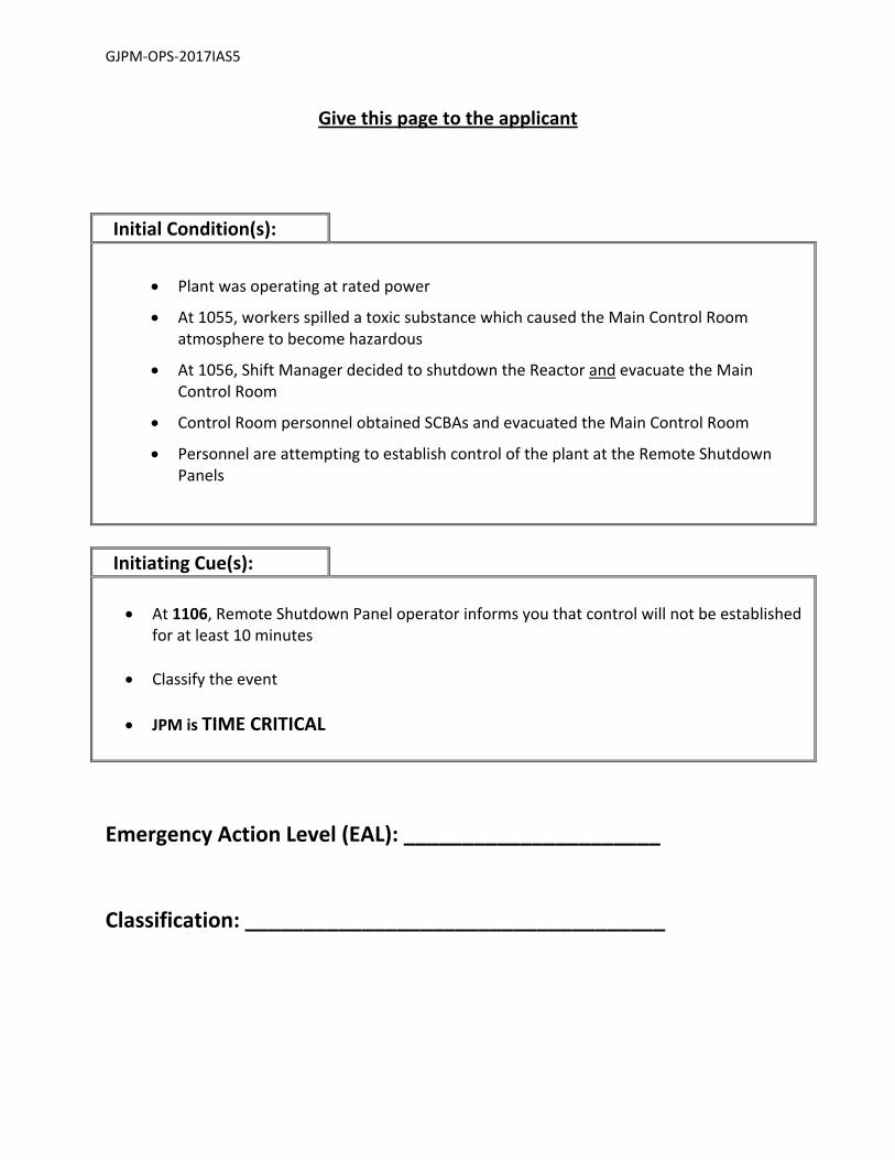
GJPM‐OPS‐2017IAS5
Give this page to the applicant
Initial Condition(s):
Plant was operating at rated power
At 1055, workers spilled a toxic substance which caused the Main Control Room atmosphere to become hazardous
At 1056, Shift Manager decided to shutdown the Reactor and evacuate the Main Control Room
Control Room personnel obtained SCBAs and evacuated the Main Control Room
Personnel are attempting to establish control of the plant at the Remote Shutdown Panels
Initiating Cue(s):
At 1106, Remote Shutdown Panel operator informs you that control will not be established for at least 10 minutes
Classify the event
JPM is TIME CRITICAL
Emergency Action Level (EAL): ______________________ Classification: ____________________________________
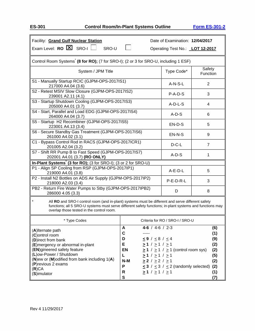
Rev 4 11/29/2017
ES-301 Control Room/In-Plant Systems Outline Form ES-301-2
Facility: Grand Gulf Nuclear Station Date of Examination: 12/04/2017
Exam Level: RO SRO-I SRO-U Operating Test No.: LOT 12-2017
Control Room Systems* (8 for RO); (7 for SRO-I); (2 or 3 for SRO-U, including 1 ESF)
System / JPM Title Type Code* Safety
Function
S1 - Manually Startup RCIC (GJPM-OPS-2017IS1) 217000 A4.04 (3.6) A-N-S-L 2
S2 - Retest MSIV Slow Closure (GJPM-OPS-2017IS2) 239001 A2.11 (4.1) P-A-D-S 3
S3 - Startup Shutdown Cooling (GJPM-OPS-2017IS3) 205000 A4.01 (3.7) A-D-L-S 4
S4 - Start, Parallel and Load EDG (GJPM-OPS-2017IS4) 264000 A4.04 (3.7) A-D-S 6
S5 - Startup H2 Recombiner (GJPM-OPS-2017IS5) 223001 A4.13 (3.4) EN-D-S 5
S6 - Secure Standby Gas Treatment (GJPM-OPS-2017IS6) 261000 A4.02 (3.1) EN-N-S 9
C1 - Bypass Control Rod in RACS (GJPM-OPS-2017ICR1) 201005 A2.04 (3.2) D-C-L 7
S7 - Shift RR Pump B to Fast Speed (GJPM-OPS-2017IS7) 202001 A4.01 (3.7) (RO ONLY) A-D-S 1
In-Plant Systems* (3 for RO); (3 for SRO-I); (3 or 2 for SRO-U)P1 - Align SP Cooling from RSP (GJPM-OPS-2017IP1)
219000 A4.01 (3.8) A-E-D-L 5
P2 - Install N2 Bottles on ADS Air Supply (GJPM-OPS-2017IP2) 218000 A2.03 (3.4) P-E-D-R-L 3
PB2 - Return Fire Water Pumps to Stby (GJPM-OPS-2017IPB2) 286000 4.05 (3.3) D 8
* All RO and SRO-I control room (and in-plant) systems must be different and serve different safety functions; all 5 SRO-U systems must serve different safety functions; in-plant systems and functions may overlap those tested in the control room.
* Type Codes Criteria for RO / SRO-I / SRO-U
(A)lternate path (C)ontrol room (D)irect from bank (E)mergency or abnormal in-plant (EN)gineered safety feature (L)ow-Power / Shutdown (N)ew or (M)odified from bank including 1(A) (P)revious 2 exams (R)CA (S)imulator
A 4-6 / 4-6 / 2-3 (6) C ----- (1) D < 9 / < 8 / < 4 (9) E > 1 / > 1 / > 1 (2) EN > 1 / > 1 / > 1 (control room sys) (2) L > 1 / > 1 / > 1 (5) N-M > 2 / > 2 / > 1 (2) P < 3 / < 3 / < 2 (randomly selected) (2) R > 1 / > 1 / > 1 (1) S (7)
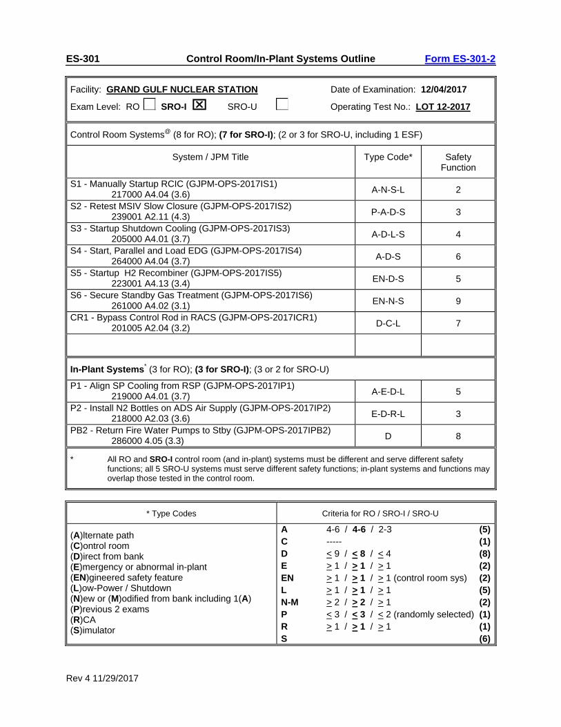
Rev 4 11/29/2017
ES-301 Control Room/In-Plant Systems Outline Form ES-301-2
Facility: GRAND GULF NUCLEAR STATION Date of Examination: 12/04/2017
Exam Level: RO SRO-I SRO-U Operating Test No.: LOT 12-2017
Control Room Systems@ (8 for RO); (7 for SRO-I); (2 or 3 for SRO-U, including 1 ESF)
System / JPM Title Type Code* Safety Function
S1 - Manually Startup RCIC (GJPM-OPS-2017IS1) 217000 A4.04 (3.6) A-N-S-L 2
S2 - Retest MSIV Slow Closure (GJPM-OPS-2017IS2) 239001 A2.11 (4.3) P-A-D-S 3
S3 - Startup Shutdown Cooling (GJPM-OPS-2017IS3) 205000 A4.01 (3.7) A-D-L-S 4
S4 - Start, Parallel and Load EDG (GJPM-OPS-2017IS4) 264000 A4.04 (3.7) A-D-S 6
S5 - Startup H2 Recombiner (GJPM-OPS-2017IS5) 223001 A4.13 (3.4) EN-D-S 5
S6 - Secure Standby Gas Treatment (GJPM-OPS-2017IS6) 261000 A4.02 (3.1) EN-N-S 9
CR1 - Bypass Control Rod in RACS (GJPM-OPS-2017ICR1) 201005 A2.04 (3.2) D-C-L 7
In-Plant Systems* (3 for RO); (3 for SRO-I); (3 or 2 for SRO-U)
P1 - Align SP Cooling from RSP (GJPM-OPS-2017IP1) 219000 A4.01 (3.7) A-E-D-L 5
P2 - Install N2 Bottles on ADS Air Supply (GJPM-OPS-2017IP2) 218000 A2.03 (3.6) E-D-R-L 3
PB2 - Return Fire Water Pumps to Stby (GJPM-OPS-2017IPB2) 286000 4.05 (3.3) D 8
* All RO and SRO-I control room (and in-plant) systems must be different and serve different safety functions; all 5 SRO-U systems must serve different safety functions; in-plant systems and functions may overlap those tested in the control room.
* Type Codes Criteria for RO / SRO-I / SRO-U
(A)lternate path (C)ontrol room (D)irect from bank (E)mergency or abnormal in-plant (EN)gineered safety feature (L)ow-Power / Shutdown (N)ew or (M)odified from bank including 1(A) (P)revious 2 exams (R)CA (S)imulator
A 4-6 / 4-6 / 2-3 (5)C ----- (1)D < 9 / < 8 / < 4 (8)E > 1 / > 1 / > 1 (2)EN > 1 / > 1 / > 1 (control room sys) (2)L > 1 / > 1 / > 1 (5)N-M > 2 / > 2 / > 1 (2)P < 3 / < 3 / < 2 (randomly selected) (1)R > 1 / > 1 / > 1 (1)S (6)
Date of Examination: 12/04/2017 Operating Test Number: GGNS 12-2017
Facility: Grand Gulf Nuclear Station JPM Number: GJPM-OPS-2017ICR1
Revision 01 11/08/2017 Page 1 of 12
2017I CR1
GGNS
2017 NRC Operating Test
Job Performance Measure JPM Number: GJPM-OPS-2017ICR1 JPM Title: Bypass a Control Rod in RACS Facility Number: _GJPM-OPS-C11216_________ (If Bank or Modified from Bank)
JPM Attributes:
New Modified Direct from bank
Time Critical Alternate Path Validation Time: 10 min
Prepared By: Michael Rasch 11/08/2017 Exam Developer Date
Ops Review: Robert Brinkman 11/08/2017 1st Validation by Ops Rep or Ops Validation Crew Date
Validated By: Benny White \ Chase Miller 11/08/2017 2nd Validation by Ops Validation Crew Date
Approved By: Ricky Liddell 11/08/2017 Project Lead or Exam Team Lead Date
Date of Examination: 12/04/2017 Operating Test Number: GGNS 12-2017
Facility: Grand Gulf Nuclear Station JPM Number: GJPM-OPS-2017ICR1
Revision 01 11/08/2017 Page 2 of 12
Bypass a Control Rod in RACS
Time Critical Alternate Path Validation Time: 10 Min
Setting: Control Room Type: RO/SRO Task: CRO-C11(2)-OFFNORM-014 K&A: 201005 A2.03 (3.2/3.2); A2.04 (3.2/3.2); A2.06 (3.2/3.2);
A2.07 (3.2/3.2) Safety Function: 7 - Instrumentation
1 - Reactivity Control PRA Applicability: No 10CFR 55.45(a) (1); (6) Performance: Simulate Reference(s): 04-1-01-C11-2, Rev. 42, Rod Control and Information System Handout(s): 04-1-01-C11-2Precautions & Limitations; Section 5.1; Figure 1b # Manipulations: 3 # Critical Steps: 3 Low Power: YES Emergency/Abnormal: No RCA entry: No Engineered Safety Function: No Simulator Setup/Required Plant Conditions:
• Permission to open Control Room Back Panel Cabinets from the Control Room Supervisor or Shift Manager
Safety Concerns:
• Do NOT allow candidate to manipulate Control Room controls • Only point and discuss • Do NOT open access cover to the switches
Date of Examination: 12/04/2017 Operating Test Number: GGNS 12-2017
Facility: Grand Gulf Nuclear Station JPM Number: GJPM-OPS-2017ICR1
Revision 01 11/08/2017 Page 3 of 12
Name: ___________________________ Time Start: _______ Time Stop: _______
Initial Condition(s): • Reactor startup is in progress
• Rod Pattern Controller is in effect
• Control Rod 20-09 has caused a control rod block due to the rod position out of pattern
• Reactor Engineering has been consulted and concurs with bypassing the control rod
• Requirements of Engineering Procedure 17-S-02-400 have been met
• No other control rods are currently bypassed
Initiating Cue(s):
• CRS directs you to position bypass control rod 20-09 in both Rod Action Control Cabinets, starting with RACS 1
• Control Room Supervisor (CRS) gives you the key to the RACS cabinets (simulated)
• Another operator will complete Attachment V of 04-1-01-C11-2 in parallel with your performing the rod bypass
Date of Examination: 12/04/2017 Operating Test Number: GGNS 12-2017
Facility: Grand Gulf Nuclear Station JPM Number: GJPM-OPS-2017ICR1
Revision 01 11/08/2017 Page 4 of 12
Bypass a Control Rod in RACS Notes to Evaluator:
• All Control Room operations will be on panels P651 and P652 in the Main Control Room Back Panels
• Rod Action Control System (RACS)
Task Overview: (Detailed description of task)
This task is to bypass control rod positions in RACS 1 and 2 to allow Control Rod Movement to place the control rod in a specific position regardless of the Rod Pattern Controller. Bypassing a control rod in RACS is done when a control rod is out of position with regard to the Rod Pattern Controller to allow the rod to be put in pattern allowing Control Rod Blocks to be cleared. This task is performed during plant startups as required to support control rod movement when on the Rod Pattern Controller.
EVALUATOR NOTE:
After RACS 1 is completed have applicant locate RACS 2, then TERMINATE the JPM.
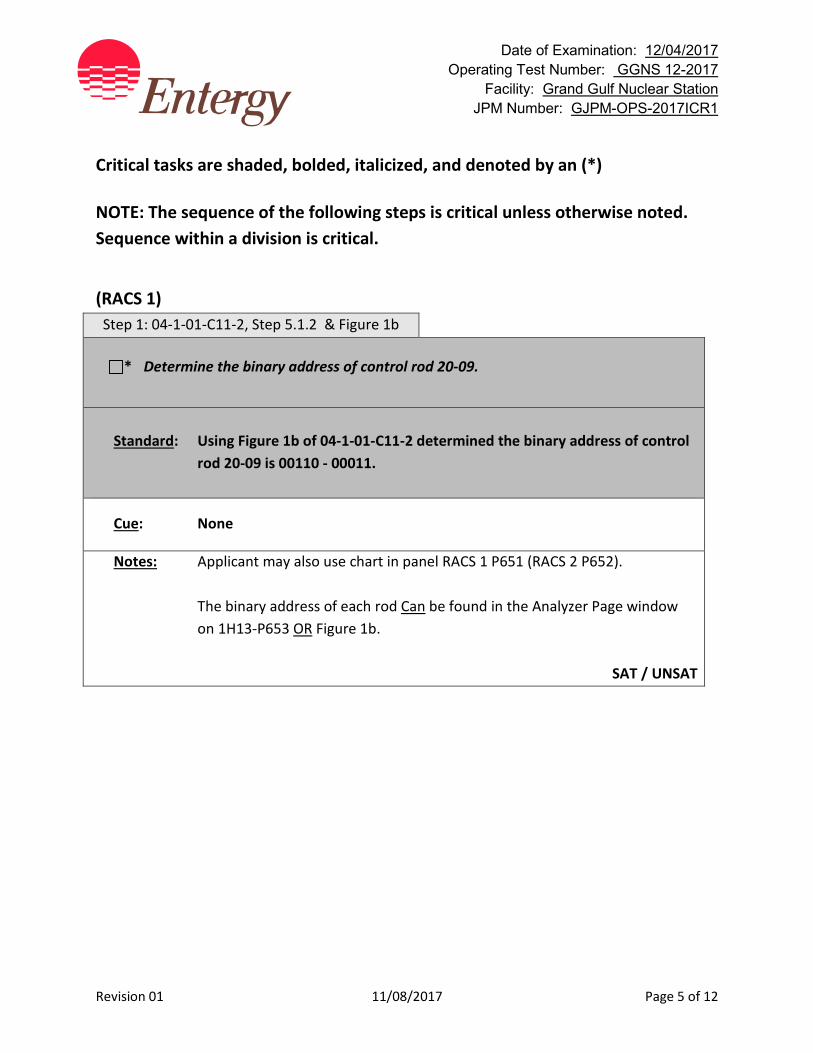
Date of Examination: 12/04/2017 Operating Test Number: GGNS 12-2017
Facility: Grand Gulf Nuclear Station JPM Number: GJPM-OPS-2017ICR1
Revision 01 11/08/2017 Page 5 of 12
Critical tasks are shaded, bolded, italicized, and denoted by an (*) NOTE: The sequence of the following steps is critical unless otherwise noted. Sequence within a division is critical.
(RACS 1) Step 1: 04-1-01-C11-2, Step 5.1.2 & Figure 1b
* Determine the binary address of control rod 20-09.
Standard: Using Figure 1b of 04-1-01-C11-2 determined the binary address of control
rod 20-09 is 00110 - 00011.
Cue: None
Notes: Applicant may also use chart in panel RACS 1 P651 (RACS 2 P652). The binary address of each rod Can be found in the Analyzer Page window
on 1H13-P653 OR Figure 1b.
SAT / UNSAT
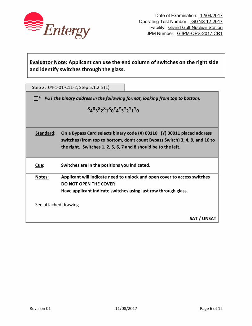
Date of Examination: 12/04/2017 Operating Test Number: GGNS 12-2017
Facility: Grand Gulf Nuclear Station JPM Number: GJPM-OPS-2017ICR1
Revision 01 11/08/2017 Page 6 of 12
Evaluator Note: Applicant can use the end column of switches on the right side and identify switches through the glass.
Step 2: 04-1-01-C11-2, Step 5.1.2 a (1)
* PUT the binary address in the following format, looking from top to bottom:
X4X3X2X1X0Y4Y3Y2Y1Y0
Standard: On a Bypass Card selects binary code (X) 00110 (Y) 00011 placed address switches (from top to bottom, don’t count Bypass Switch) 3, 4, 9, and 10 to the right. Switches 1, 2, 5, 6, 7 and 8 should be to the left.
Cue: Switches are in the positions you indicated.
Notes: Applicant will indicate need to unlock and open cover to access switches DO NOT OPEN THE COVER
Have applicant indicate switches using last row through glass. See attached drawing
SAT / UNSAT
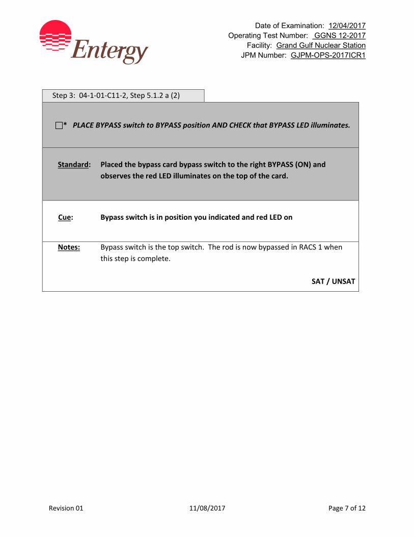
Date of Examination: 12/04/2017 Operating Test Number: GGNS 12-2017
Facility: Grand Gulf Nuclear Station JPM Number: GJPM-OPS-2017ICR1
Revision 01 11/08/2017 Page 7 of 12
Step 3: 04-1-01-C11-2, Step 5.1.2 a (2)
* PLACE BYPASS switch to BYPASS position AND CHECK that BYPASS LED illuminates.
Standard: Placed the bypass card bypass switch to the right BYPASS (ON) and
observes the red LED illuminates on the top of the card.
Cue: Bypass switch is in position you indicated and red LED on
Notes: Bypass switch is the top switch. The rod is now bypassed in RACS 1 when this step is complete.
SAT / UNSAT
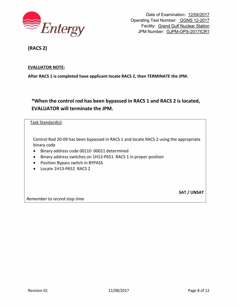
Date of Examination: 12/04/2017 Operating Test Number: GGNS 12-2017
Facility: Grand Gulf Nuclear Station JPM Number: GJPM-OPS-2017ICR1
Revision 01 11/08/2017 Page 8 of 12
(RACS 2) EVALUATOR NOTE:
After RACS 1 is completed have applicant locate RACS 2, then TERMINATE the JPM.
*When the control rod has been bypassed in RACS 1 and RACS 2 is located, EVALUATOR will terminate the JPM.
Task Standard(s):
Control Rod 20-09 has been bypassed in RACS 1 and locate RACS 2 using the appropriate binary code • Binary address code 00110 00011 determined • Binary address switches on 1H13-P651 RACS 1 in proper position • Position Bypass switch in BYPASS • Locate 1H13-P652 RACS 2
SAT / UNSAT Remember to record stop time
Date of Examination: 12/04/2017 Operating Test Number: GGNS 12-2017
Facility: Grand Gulf Nuclear Station JPM Number: GJPM-OPS-2017ICR1
Revision 01 11/08/2017 Page 9 of 12
Follow-Up Questions & Answers:
Comments:
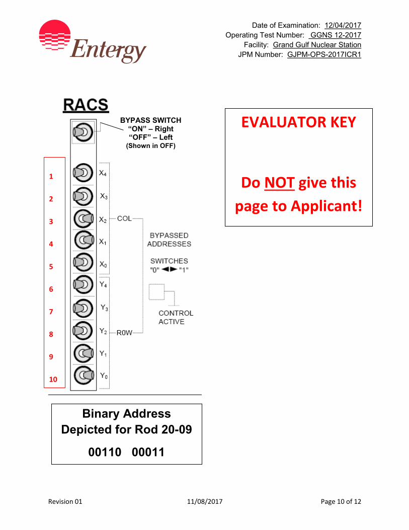
Date of Examination: 12/04/2017 Operating Test Number: GGNS 12-2017
Facility: Grand Gulf Nuclear Station JPM Number: GJPM-OPS-2017ICR1
Revision 01 11/08/2017 Page 10 of 12
BYPASS SWITCH “ON” – Right “OFF” – Left
(Shown in OFF)
EVALUATOR KEY
Do NOT give this page to Applicant!
Binary Address Depicted for Rod 20-09
00110 00011
1 2 3 4 5 6 7 8 9 10
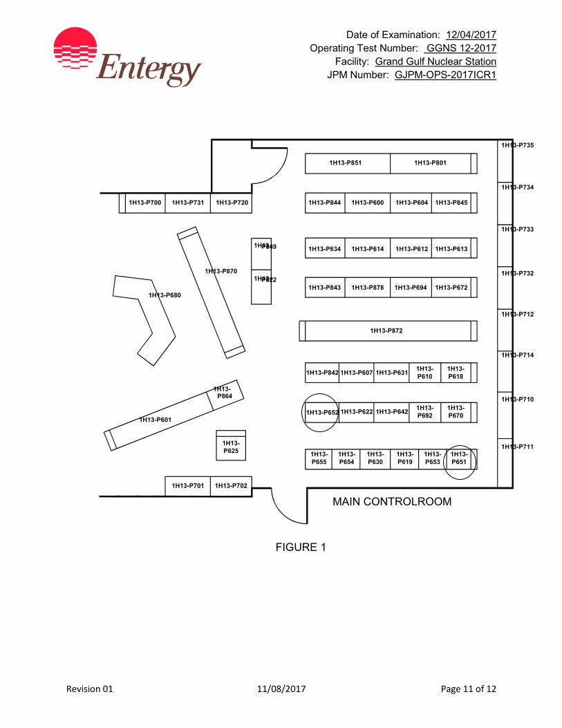
Date of Examination: 12/04/2017 Operating Test Number: GGNS 12-2017
Facility: Grand Gulf Nuclear Station JPM Number: GJPM-OPS-2017ICR1
Revision 01 11/08/2017 Page 11 of 12
1H13-P700 1H13-P731 1H13-P720
1H13-P735
1H13-P734
1H13-P733
1H13-P732
1H13-P712
1H13-P714
1H13-P710
1H13-P711
1H13- P849
1H13- P822
1H13-P844 1H13-P600 1H13-P604 1H13-P845
1H13-P851 1H13-P801
1H13-P634 1H13-P614 1H13-P612 1H13-P613
1H13-P843 1H13-P878 1H13-P694 1H13-P672
1H13-P872
1H13-P842 1H13-P607 1H13-P631 1H13- P610
1H13- P618
1H13-P652 1H13-P622 1H13-P642 1H13- P692
1H13- P670
1H13- P655
1H13- P654
1H13- P630
1H13- P619
1H13- P653
1H13- P651
1H13-P701 1H13-P702
1H13- P625
1H13-P601
1H13- P864
1H13-P870
1H13-P680
MAIN CONTROLROOM
FIGURE 1

GJPM-OPS-2017ICR1
Give this page to the applicant
Initial Condition(s): • Reactor startup is in progress
• Rod Pattern Controller is in effect
• Control Rod 20-09 has caused a control rod block due to the rod position out of pattern
• Reactor Engineering has been consulted and concurs with bypassing the control rod
• Requirements of Engineering Procedure 17-S-02-400 have been met
• No other control rods are currently bypassed
Initiating Cue(s):
• CRS directs you to position bypass control rod 20-09 in both Rod Action Control Cabinets, starting with RACS 1
• Control Room Supervisor (CRS) gives you the key to the RACS cabinets (simulated)
• Another operator will complete Attachment V of 04-1-01-C11-2 in parallel with your performing the rod bypass
Date of Examination: 12/04/2017 Operating Test Number: GGNS 12-2017
Facility: Grand Gulf Nuclear Station JPM Number: GJPM-OPS-2017IS1
Rev. 03 12/01/2017 Page 1 of 15
2017I S1
GGNS
2017 NRC Operating Test
Job Performance Measure JPM Number: GJPM-OPS-2017IS1 JPM Title: Manually Startup RCIC Facility Number: _GJPM-OPS-E5103& E5105__ (If Bank or Modified from Bank)
JPM Attributes:
New Modified Direct from bank
Time Critical Alternate Path Validation Time: 10 min
Prepared By: Michael Rasch 11/08/2017 Exam Developer Date
Ops Review: Robert Brinkman 11/08/2017 1st Validation by Ops Rep or Ops Validation Crew Date
Validated By: Benny White \ Chase Miller 11/08/2017 2nd Validation by Ops Validation Crew Date
Approved By: Ricky Liddell 11/08/2017 Project Lead or Exam Team Lead Date
Date of Examination: 12/04/2017 Operating Test Number: GGNS 12-2017
Facility: Grand Gulf Nuclear Station JPM Number: GJPM-OPS-2017IS1
Rev. 03 12/01/2017 Page 2 of 15
Manually Startup RCIC
Time Critical Alternate Path Validation Time: 10 Min
Setting: Simulator Type: RO/SRO Task: GGNS-CRO-E51-EMERGENCY-3 K&A: 217000 A4.03 (3.4/3.3); A4.04 (3.6/3.6) Safety Function: 2 – Reactor Water Inventory Control 4 – Heat Removal from Reactor Core PRA Applicability: System Importance to Core Damage Frequency rank 17 10CFR 55.45(a) (3); (4); (7) Performance: Perform Reference(s): 04-1-01-E51-1, Reactor Core Isolation Cooling
System, Rev. 136 EN-OP-200, Plant Transient Response Rules, Rev. 3 Handout(s): 04-1-01-E51-1, Attachment VI, Hard Card # Manipulations: 8 # Critical Steps: 6 Low Power: YES Emergency/Abnormal: YES RCA entry: No Engineered Safety Function: No Simulator Setup/Required Plant Conditions:
• Reset Simulator to any full power IC • Run Schedule File 12-2017NRC JPM 2017IS1 • Insert Malfunction e22052 HPCS Pump Trip • Insert Malfunction fw070a FW Line A Rupture Outside Containment @ 100% • Insert Malfunction e51043 RCIC Auto Start Failure • Insert Malfunction di_1e51m625d P601/21B RCIC MAN INIT Depress - NORM • Insert Malfunction E51187c, “Failure of valve E51-F045” • Based on E51F095 open - AO_1E51R605 ramp to 1500 rpm over 30 seconds • Remove override on 1E51R605 1500 rpm to 0 rpm over 10 seconds when either:
o iodie51m612c(1)=1 RCIC Trip Pushbutton depressed OR o zdi4(769)=(1) E51F095 H/S to CLOSE OR o zdi4(385)=(1) RCIC Trip Throttle valve H/S to CLOSE
Safety Concerns: None
Date of Examination: 12/04/2017 Operating Test Number: GGNS 12-2017
Facility: Grand Gulf Nuclear Station JPM Number: GJPM-OPS-2017IS1
Rev. 03 12/01/2017 Page 3 of 15
Name: _______________________ Time Start: _______ Time Stop: _______
Initial Condition(s):
• Loss of Coolant Accident is in progress
• RCIC is in STANDBY mode
• High Pressure Core Spray is unavailable
• RCIC auto start has failed
• Condensate and Feedwater are unavailable for injection
Initiating Cue(s):
Control Room Supervisor directs you to start RCIC and inject to the RPV at maximum rate
Date of Examination: 12/04/2017 Operating Test Number: GGNS 12-2017
Facility: Grand Gulf Nuclear Station JPM Number: GJPM-OPS-2017IS1
Rev. 03 12/01/2017 Page 4 of 15
Manually Startup RCIC Notes to Evaluator:
• Unless otherwise stated, all control manipulations will be at panel P601 in the Main Control Room.
Task Overview: (Detailed description of task)
With a LOCA in progress, RCIC should automatically start when RPV level drops to - 41.6”. If RCIC fails to start or as directed to be started by the Control Room Supervisor, then the operator should use 04-1-01-E51-1 Att. VI Hard Card. Hard Card has two options to start RCIC: 1) Preferred method is Manual Initiation Pushbutton 2) Controlled Start which is manual realignment of system valves The faults in this task are:
1) Manual initiation will fail to start RCIC 2) Failure of the RCIC Steam Supply valve E51-F045 to open o RCIC turbine will operate below minimal speed with this valve closed o Initial speed is generated by open steam bypass valve E51-F095 o Turbine speed developed by bypass steam is not enough to develop
any significant system flow or pressure
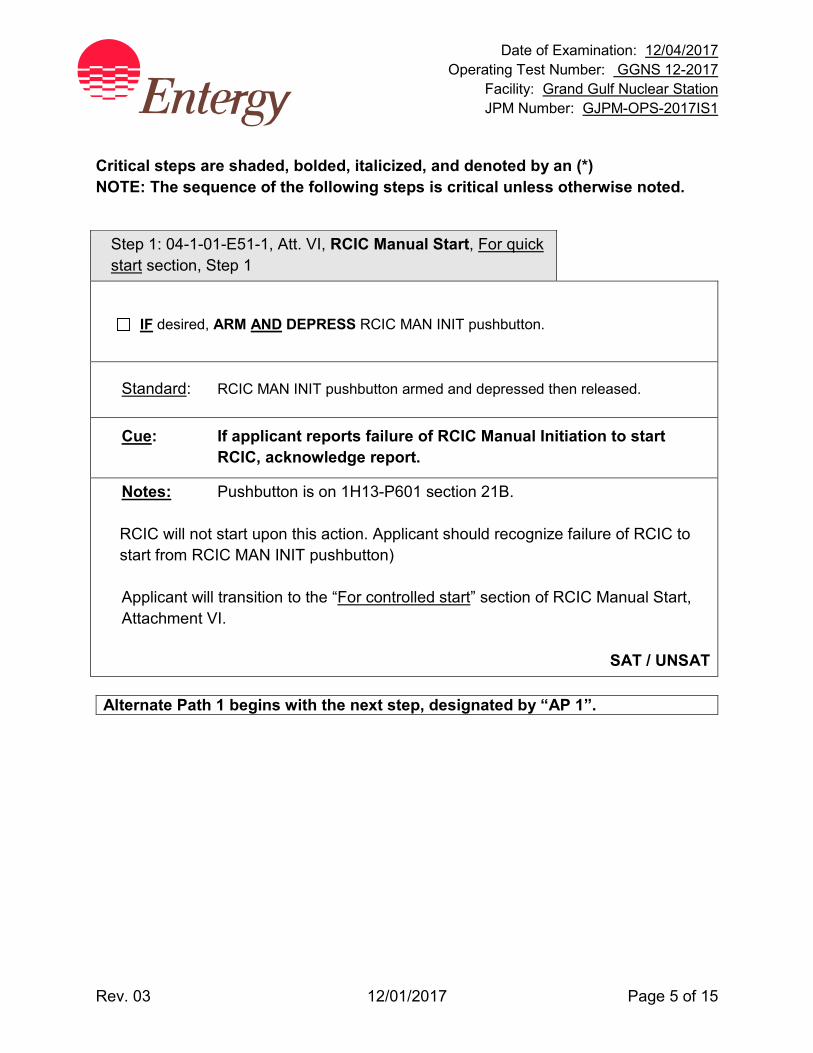
Date of Examination: 12/04/2017 Operating Test Number: GGNS 12-2017
Facility: Grand Gulf Nuclear Station JPM Number: GJPM-OPS-2017IS1
Rev. 03 12/01/2017 Page 5 of 15
Critical steps are shaded, bolded, italicized, and denoted by an (*) NOTE: The sequence of the following steps is critical unless otherwise noted.
Step 1: 04-1-01-E51-1, Att. VI, RCIC Manual Start, For quick start section, Step 1
IF desired, ARM AND DEPRESS RCIC MAN INIT pushbutton.
Standard: RCIC MAN INIT pushbutton armed and depressed then released.
Cue: If applicant reports failure of RCIC Manual Initiation to start RCIC, acknowledge report.
Notes: Pushbutton is on 1H13-P601 section 21B. RCIC will not start upon this action. Applicant should recognize failure of RCIC to start from RCIC MAN INIT pushbutton) Applicant will transition to the “For controlled start” section of RCIC Manual Start, Attachment VI.
SAT / UNSAT
Alternate Path 1 begins with the next step, designated by “AP 1”.
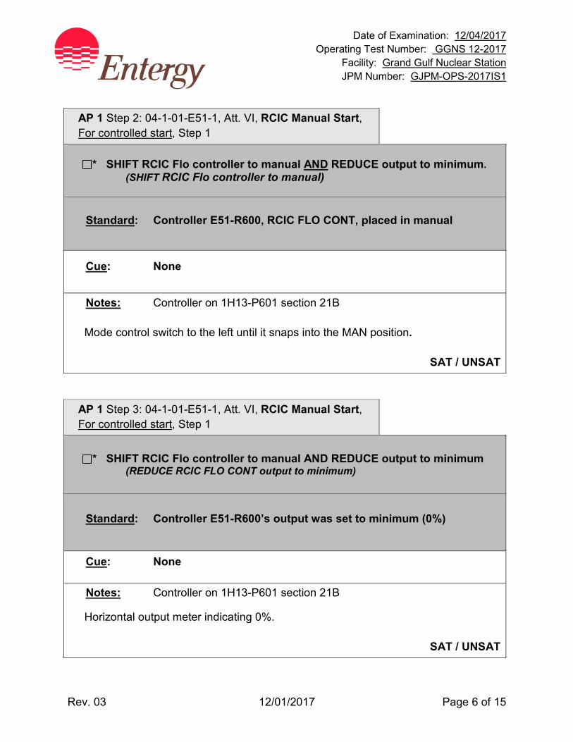
Date of Examination: 12/04/2017 Operating Test Number: GGNS 12-2017
Facility: Grand Gulf Nuclear Station JPM Number: GJPM-OPS-2017IS1
Rev. 03 12/01/2017 Page 6 of 15
AP 1 Step 2: 04-1-01-E51-1, Att. VI, RCIC Manual Start, For controlled start, Step 1
* SHIFT RCIC Flo controller to manual AND REDUCE output to minimum. (SHIFT RCIC Flo controller to manual)
Standard: Controller E51-R600, RCIC FLO CONT, placed in manual
Cue: None
Notes: Controller on 1H13-P601 section 21B
Mode control switch to the left until it snaps into the MAN position.
SAT / UNSAT
AP 1 Step 3: 04-1-01-E51-1, Att. VI, RCIC Manual Start, For controlled start, Step 1
* SHIFT RCIC Flo controller to manual AND REDUCE output to minimum (REDUCE RCIC FLO CONT output to minimum)
Standard: Controller E51-R600’s output was set to minimum (0%)
Cue: None
Notes: Controller on 1H13-P601 section 21B
Horizontal output meter indicating 0%.
SAT / UNSAT

Date of Examination: 12/04/2017 Operating Test Number: GGNS 12-2017
Facility: Grand Gulf Nuclear Station JPM Number: GJPM-OPS-2017IS1
Rev. 03 12/01/2017 Page 7 of 15
AP 1 Step 4: 04-1-01-E51-1, Att. VI, RCIC Manual Start, For controlled start, Step 2
* OPEN E51-F046
Standard: E51-F046, RCIC WTR TO TURB LUBE OIL CLR, was opened
(Indication - red light on, green light off )
Cue: None
Notes: 1H13-P601 section 21C
SAT / UNSAT
AP 1 Step 5: 04-1-01-E51-1, Att. VI, RCIC Manual Start, For controlled start, Step 3
START Gland Seal Compressor.
Standard: RCIC Turbine Gland Seal Compressor was started USING RCIC GL
SEAL COMPR handswitch
(Indication - red light on, green light off)
Cue: None
Notes: 1H13-P601 section 21C
SAT / UNSAT
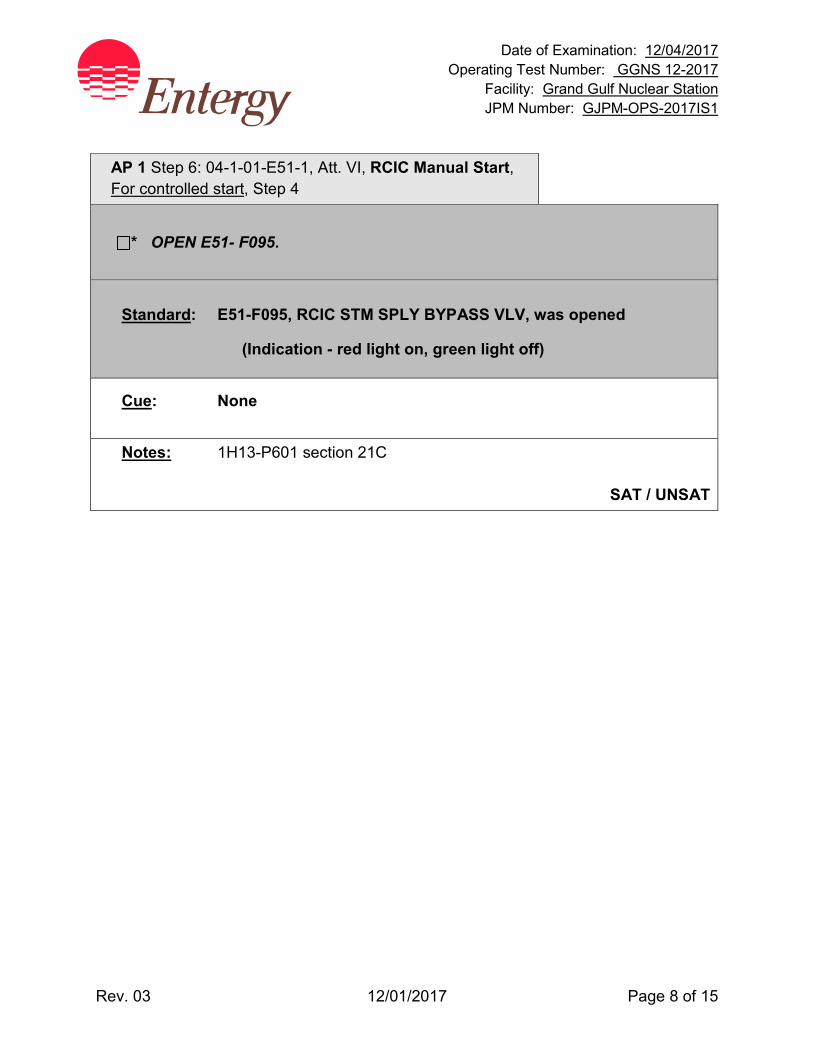
Date of Examination: 12/04/2017 Operating Test Number: GGNS 12-2017
Facility: Grand Gulf Nuclear Station JPM Number: GJPM-OPS-2017IS1
Rev. 03 12/01/2017 Page 8 of 15
AP 1 Step 6: 04-1-01-E51-1, Att. VI, RCIC Manual Start, For controlled start, Step 4
* OPEN E51- F095.
Standard: E51-F095, RCIC STM SPLY BYPASS VLV, was opened
(Indication - red light on, green light off)
Cue: None
Notes: 1H13-P601 section 21C
SAT / UNSAT
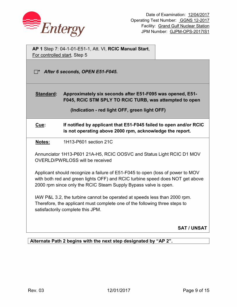
Date of Examination: 12/04/2017 Operating Test Number: GGNS 12-2017
Facility: Grand Gulf Nuclear Station JPM Number: GJPM-OPS-2017IS1
Rev. 03 12/01/2017 Page 9 of 15
AP 1 Step 7: 04-1-01-E51-1, Att. VI, RCIC Manual Start, For controlled start, Step 5
* After 6 seconds, OPEN E51-F045.
Standard: Approximately six seconds after E51-F095 was opened, E51-
F045, RCIC STM SPLY TO RCIC TURB, was attempted to open
(Indication - red light OFF, green light OFF)
Cue: If notified by applicant that E51-F045 failed to open and/or RCIC is not operating above 2000 rpm, acknowledge the report.
Notes: 1H13-P601 section 21C
Annunciator 1H13-P601 21A-H5, RCIC OOSVC and Status Light RCIC D1 MOV OVERLD/PWRLOSS will be received
Applicant should recognize a failure of E51-F045 to open (loss of power to MOV with both red and green lights OFF) and RCIC turbine speed does NOT get above 2000 rpm since only the RCIC Steam Supply Bypass valve is open. IAW P&L 3.2, the turbine cannot be operated at speeds less than 2000 rpm. Therefore, the applicant must complete one of the following three steps to satisfactorily complete this JPM.
SAT / UNSAT
Alternate Path 2 begins with the next step designated by “AP 2”.

Date of Examination: 12/04/2017 Operating Test Number: GGNS 12-2017
Facility: Grand Gulf Nuclear Station JPM Number: GJPM-OPS-2017IS1
Rev. 03 12/01/2017 Page 10 of 15
Option 1
AP 2 Step 8: 04-1-01-E51-1, Att. VI RCIC Manual Start, For controlled start, Reverse Step 4; EN-OP-200 step 4.0[1](c)(1)b
* Close E51-F095 (steam supply to the RCIC turbine)
Standard: E51-F095, RCIC STM SPLY BYPASS VLV was CLOSED by
backing out of procedure used to open E51-F095
(Indication red light is off and green light is on)
Cue: None
Notes: 1H13-P601 section 21C This action backs out of this section of the procedure by closing the previously opened RCIC Steam Supply Bypass valve. This step is allowed by EN-OP-200, Plant Transient Response Rules, Section 4.0 [1](c)(1)b: “When faced with unexpected or uncertain conditions, licensed operators should place the plant in a safe condition and should not hesitate to reduce power or initiate an immediate reactor shutdown.” When the RCIC Steam Supply Bypass valve is closed, this JPM is complete.
EVALUATOR TERMINATE JPM.
SAT / UNSAT
OR
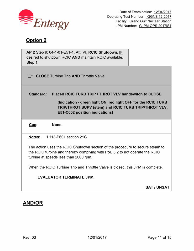
Date of Examination: 12/04/2017 Operating Test Number: GGNS 12-2017
Facility: Grand Gulf Nuclear Station JPM Number: GJPM-OPS-2017IS1
Rev. 03 12/01/2017 Page 11 of 15
Option 2 AP 2 Step 9: 04-1-01-E51-1, Att. VI, RCIC Shutdown, IF desired to shutdown RCIC AND maintain RCIC available, Step 1
* CLOSE Turbine Trip AND Throttle Valve
Standard: Placed RCIC TURB TRIP / THROT VLV handswitch to CLOSE
(Indication - green light ON, red light OFF for the RCIC TURB TRIP/THROT SUPV (stem) and RCIC TURB TRIP/THROT VLV, E51-C002 position indications)
Cue: None
Notes: 1H13-P601 section 21C The action uses the RCIC Shutdown section of the procedure to secure steam to the RCIC turbine and thereby complying with P&L 3.2 to not operate the RCIC turbine at speeds less than 2000 rpm. When the RCIC Turbine Trip and Throttle Valve is closed, this JPM is complete.
EVALUATOR TERMINATE JPM.
SAT / UNSAT AND/OR
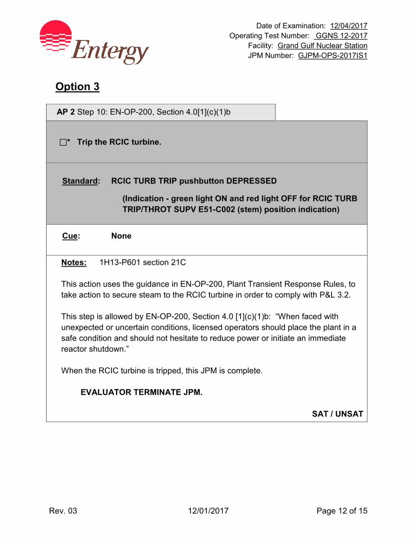
Date of Examination: 12/04/2017 Operating Test Number: GGNS 12-2017
Facility: Grand Gulf Nuclear Station JPM Number: GJPM-OPS-2017IS1
Rev. 03 12/01/2017 Page 12 of 15
Option 3
AP 2 Step 10: EN-OP-200, Section 4.0[1](c)(1)b
* Trip the RCIC turbine.
Standard: RCIC TURB TRIP pushbutton DEPRESSED
(Indication - green light ON and red light OFF for RCIC TURB TRIP/THROT SUPV E51-C002 (stem) position indication)
Cue: None
Notes: 1H13-P601 section 21C This action uses the guidance in EN-OP-200, Plant Transient Response Rules, to take action to secure steam to the RCIC turbine in order to comply with P&L 3.2. This step is allowed by EN-OP-200, Section 4.0 [1](c)(1)b: “When faced with unexpected or uncertain conditions, licensed operators should place the plant in a safe condition and should not hesitate to reduce power or initiate an immediate reactor shutdown.” When the RCIC turbine is tripped, this JPM is complete.
EVALUATOR TERMINATE JPM.
SAT / UNSAT

Date of Examination: 12/04/2017 Operating Test Number: GGNS 12-2017
Facility: Grand Gulf Nuclear Station JPM Number: GJPM-OPS-2017IS1
Rev. 03 12/01/2017 Page 13 of 15
Task Standard(s): Completed the following steps:
• Shifted RCIC FLO CONT to Manual
• Lowered RCIC FLO CONT output to 0%
• Opened E51-F046
• Opened E51-F095
• Opened E51-F045 When RCIC Steam Supply E51-F045 could not be opened and RCIC turbine speed could not be raised to greater than 2000 rpm, completed at least of the following options:
• Option 1 – E51-F095, RCIC STM SPLY BYPASS VLV, closed
• Option 2 – RCIC Turbine Trip and Throttle Valve (E51-C002) closed
• Option 3 – RCIC TURB TRIP pushbutton depressed
SAT / UNSAT Remember to record stop time
Date of Examination: 12/04/2017 Operating Test Number: GGNS 12-2017
Facility: Grand Gulf Nuclear Station JPM Number: GJPM-OPS-2017IS1
Rev. 03 12/01/2017 Page 14 of 15
Follow-Up Questions & Answers:
Comments:
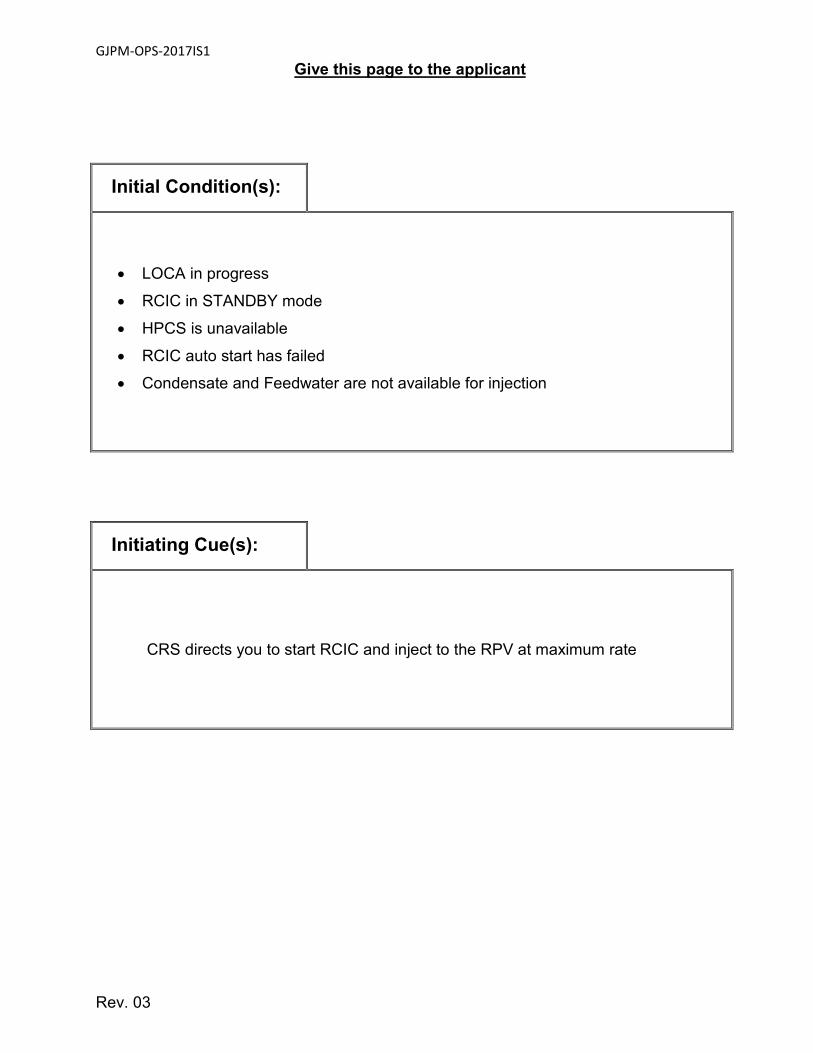
GJPM-OPS-2017IS1
Rev. 03
Give this page to the applicant
Initial Condition(s):
• LOCA in progress
• RCIC in STANDBY mode
• HPCS is unavailable
• RCIC auto start has failed
• Condensate and Feedwater are not available for injection
Initiating Cue(s):
CRS directs you to start RCIC and inject to the RPV at maximum rate
Date of Examination: 12/04/2017 Operating Test Number: GGNS 12-2017
Facility: Grand Gulf Nuclear Station JPM Number: GJPM-OPS-2017IS2
Rev. 01 11/08/2017 Page 1 of 13
2017I S2 GGNS
2017 NRC Operating Test Job Performance Measure
JPM Number: GJPM-OPS-2017IS2 JPM Title: Retest MSIV Slow Closure Facility Number: GJPM-OPS-2015S3 (If Bank or Modified from Bank)
JPM Attributes:
New Modified Direct from bank
Time Critical Alternate Path Validation Time: 10 Min
Prepared By: Michael Rasch 11/08/2017 Exam Developer Date
Ops Review: Robert Brinkman 11/08/2017 1st Validation by Ops Rep or Ops Validation Crew Date
Validated By: Benny White \ Chase Miller 11/08/2017 2nd Validation by Ops Validation Crew Date
Approved By: Ricky Liddell 11/08/2017 Project Lead or Exam Team Lead Date
Date of Examination: 12/04/2017 Operating Test Number: GGNS 12-2017
Facility: Grand Gulf Nuclear Station JPM Number: GJPM-OPS-2017IS2
Rev. 01 11/08/2017 Page 2 of 13
Retest MSIV Slow Closure
Time Critical Alternate Path Validation Time: 10 Min
Setting: Simulator Type: RO/SRO Task: CRO-B21-SU/SD-001 K&A: 239001: A2.11 (4.1/4.3); A3.01 (4.2/4.1); A4.01 (4.2/4.0) Safety Function: 3 - Reactor Pressure Control PRA Applicability: Accident Type Contribution to Core Damage
Frequency - Break Outside Containment 10CFR 55.45(a) (3); (4); (8) Performance: Perform Reference(s): 04-1-01-B21-1, Rev. 52, Nuclear Boiler System 05-1-02-III-5, Rev. 49, Automatic Isolations EN-OP-120, Rev. 1, Operator Fundamentals Program Handout(s): 04-1-01-B21-1 Step 5.4 # Manipulations: 11 # Critical Steps: 10 Low Power: No Emergency/Abnormal: YES RCA entry: No Engineered Safety Function: No Previous 2 NRC Exams (2015 randomly selected) Simulator Setup/Required Plant Conditions:
• Reset Simulator to IC-28 • Schedule File 12-2017 NRC JPM 2017IS2 • Create event 1 iodib21m603a(1)==1 • Insert malfunction ms066d to 50.00 - Steam Leak in Aux Bldg Tunnel: MSL D • Insert remote function ATT09 to DONE - Defeating all MSIV and MSL Drain
Isolation Interlocks • Icon on 1H13-P680 right side PDS Operator Guide - EP4EP4EP4
Safety Concerns:
• None
Date of Examination: 12/04/2017 Operating Test Number: GGNS 12-2017
Facility: Grand Gulf Nuclear Station JPM Number: GJPM-OPS-2017IS2
Rev. 01 11/08/2017 Page 3 of 13
Name: ________________________ Time Start: _______ Time Stop: _______
Initial Condition(s):
• Plant is approximately 58% power during initial startup after refueling outage
• MSIV, B21-F028A, was reworked during the outage
Initiating Cue(s):
• Control Room Supervisor directs you to perform a slow closing of MSIV B21-F028A, using 04-1-01-B21-1, Nuclear Boiler System SOI, section 5.4
• After MSIV B21-F028A reaches full closed, place handswitch for B21-F028A to the CLOSE position for data collection
Date of Examination: 12/04/2017 Operating Test Number: GGNS 12-2017
Facility: Grand Gulf Nuclear Station JPM Number: GJPM-OPS-2017IS2
Rev. 01 11/08/2017 Page 4 of 13
Retest MSIV Slow Closure Notes to Evaluator:
• All controls and indications for this task are on panel P601
Task Overview: (Detailed description of task)
This task is to perform a slow closure on MSIV B21-F028A. Following the closure of the MSIV, recognize High - High temperature in Main Steam Tunnel without Group 1 MSIV isolation. Applicant should manually close all remaining MSIVs (7) using handswitches on P601 panel to isolate the steam leak. At initial power level Main Steam Line Drains should be closed with the exception of B21-F019, INBD MSL DR OTBD DR VLV which has another valve in the line already closed B21-F016, INBD MSL DR INBD DR VLV.
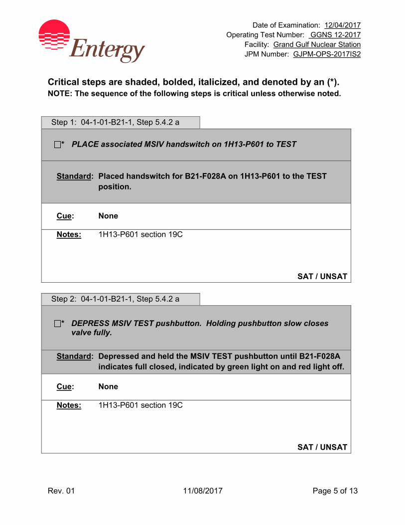
Date of Examination: 12/04/2017 Operating Test Number: GGNS 12-2017
Facility: Grand Gulf Nuclear Station JPM Number: GJPM-OPS-2017IS2
Rev. 01 11/08/2017 Page 5 of 13
Critical steps are shaded, bolded, italicized, and denoted by an (*). NOTE: The sequence of the following steps is critical unless otherwise noted.
Step 1: 04-1-01-B21-1, Step 5.4.2 a
* PLACE associated MSIV handswitch on 1H13-P601 to TEST Standard: Placed handswitch for B21-F028A on 1H13-P601 to the TEST
position.
Cue: None
Notes: 1H13-P601 section 19C
SAT / UNSAT Step 2: 04-1-01-B21-1, Step 5.4.2 a
* DEPRESS MSIV TEST pushbutton. Holding pushbutton slow closes valve fully.
Standard: Depressed and held the MSIV TEST pushbutton until B21-F028A indicates full closed, indicated by green light on and red light off.
Cue: None
Notes: 1H13-P601 section 19C
SAT / UNSAT
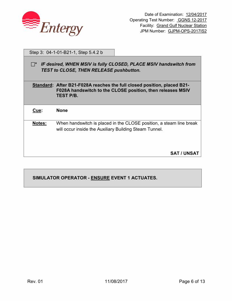
Date of Examination: 12/04/2017 Operating Test Number: GGNS 12-2017
Facility: Grand Gulf Nuclear Station JPM Number: GJPM-OPS-2017IS2
Rev. 01 11/08/2017 Page 6 of 13
Step 3: 04-1-01-B21-1, Step 5.4.2 b
* IF desired, WHEN MSIV is fully CLOSED, PLACE MSIV handswitch from TEST to CLOSE, THEN RELEASE pushbutton.
Standard: After B21-F028A reaches the full closed position, placed B21-F028A handswitch to the CLOSE position, then releases MSIV TEST P/B.
Cue: None
Notes: When handswitch is placed in the CLOSE position, a steam line break will occur inside the Auxiliary Building Steam Tunnel.
SAT / UNSAT SIMULATOR OPERATOR - ENSURE EVENT 1 ACTUATES.
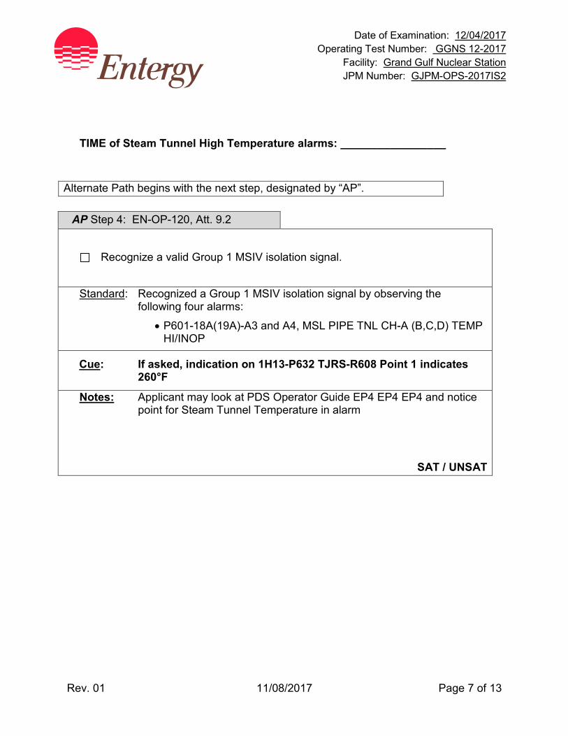
Date of Examination: 12/04/2017 Operating Test Number: GGNS 12-2017
Facility: Grand Gulf Nuclear Station JPM Number: GJPM-OPS-2017IS2
Rev. 01 11/08/2017 Page 7 of 13
TIME of Steam Tunnel High Temperature alarms: _________________
Alternate Path begins with the next step, designated by “AP”.
AP Step 4: EN-OP-120, Att. 9.2
Recognize a valid Group 1 MSIV isolation signal.
Standard: Recognized a Group 1 MSIV isolation signal by observing the following four alarms:
• P601-18A(19A)-A3 and A4, MSL PIPE TNL CH-A (B,C,D) TEMP HI/INOP
Cue: If asked, indication on 1H13-P632 TJRS-R608 Point 1 indicates 260°F
Notes: Applicant may look at PDS Operator Guide EP4 EP4 EP4 and notice point for Steam Tunnel Temperature in alarm
SAT / UNSAT
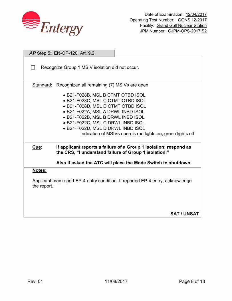
Date of Examination: 12/04/2017 Operating Test Number: GGNS 12-2017
Facility: Grand Gulf Nuclear Station JPM Number: GJPM-OPS-2017IS2
Rev. 01 11/08/2017 Page 8 of 13
AP Step 5: EN-OP-120, Att. 9.2
Recognize Group 1 MSIV isolation did not occur.
Standard: Recognized all remaining (7) MSIVs are open
• B21-F028B, MSL B CTMT OTBD ISOL • B21-F028C, MSL C CTMT OTBD ISOL • B21-F028D, MSL D CTMT OTBD ISOL • B21-F022A, MSL A DRWL INBD ISOL • B21-F022B, MSL B DRWL INBD ISOL • B21-F022C, MSL C DRWL INBD ISOL • B21-F022D, MSL D DRWL INBD ISOL
Indication of MSIVs open is red lights on, green lights off
Cue: If applicant reports a failure of a Group 1 isolation; respond as the CRS, “I understand failure of Group 1 isolation;”
Also if asked the ATC will place the Mode Switch to shutdown. Notes: Applicant may report EP-4 entry condition. If reported EP-4 entry, acknowledge the report.
SAT / UNSAT
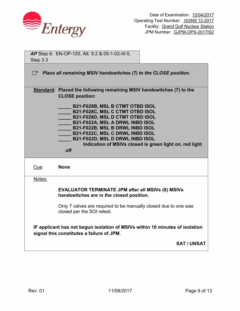
Date of Examination: 12/04/2017 Operating Test Number: GGNS 12-2017
Facility: Grand Gulf Nuclear Station JPM Number: GJPM-OPS-2017IS2
Rev. 01 11/08/2017 Page 9 of 13
AP Step 6: EN-OP-120, Att. 9.2 & 05-1-02-III-5, Step 3.3
* Place all remaining MSIV handswitches (7) to the CLOSE position.
Standard: Placed the following remaining MSIV handswitches (7) to the CLOSE position:
_____ B21-F028B, MSL B CTMT OTBD ISOL _____ B21-F028C, MSL C CTMT OTBD ISOL _____ B21-F028D, MSL D CTMT OTBD ISOL _____ B21-F022A, MSL A DRWL INBD ISOL _____ B21-F022B, MSL B DRWL INBD ISOL _____ B21-F022C, MSL C DRWL INBD ISOL _____ B21-F022D, MSL D DRWL INBD ISOL
Indication of MSIVs closed is green light on, red light off
Cue: None
Notes:
EVALUATOR TERMINATE JPM after all MSIVs (8) MSIVs handswitches are in the closed position.
Only 7 valves are required to be manually closed due to one was
closed per the SOI retest.
IF applicant has not begun isolation of MSIVs within 10 minutes of isolation signal this constitutes a failure of JPM.
SAT / UNSAT
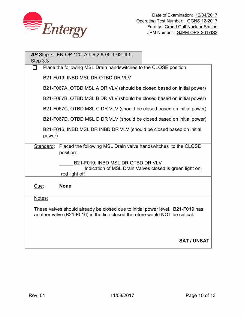
Date of Examination: 12/04/2017 Operating Test Number: GGNS 12-2017
Facility: Grand Gulf Nuclear Station JPM Number: GJPM-OPS-2017IS2
Rev. 01 11/08/2017 Page 10 of 13
AP Step 7: EN-OP-120, Att. 9.2 & 05-1-02-III-5, Step 3.3
Place the following MSL Drain handswitches to the CLOSE position.
B21-F019, INBD MSL DR OTBD DR VLV
B21-F067A, OTBD MSL A DR VLV (should be closed based on initial power)
B21-F067B, OTBD MSL B DR VLV (should be closed based on initial power)
B21-F067C, OTBD MSL C DR VLV (should be closed based on initial power)
B21-F067D, OTBD MSL D DR VLV (should be closed based on initial power)
B21-F016, INBD MSL DR INBD DR VLV (should be closed based on initial power)
Standard: Placed the following MSL Drain valve handswitches to the CLOSE position:
_____ B21-F019, INBD MSL DR OTBD DR VLV Indication of MSL Drain Valves closed is green light on, red light off
Cue: None
Notes: These valves should already be closed due to initial power level. B21-F019 has another valve (B21-F016) in the line closed therefore would NOT be critical.
SAT / UNSAT
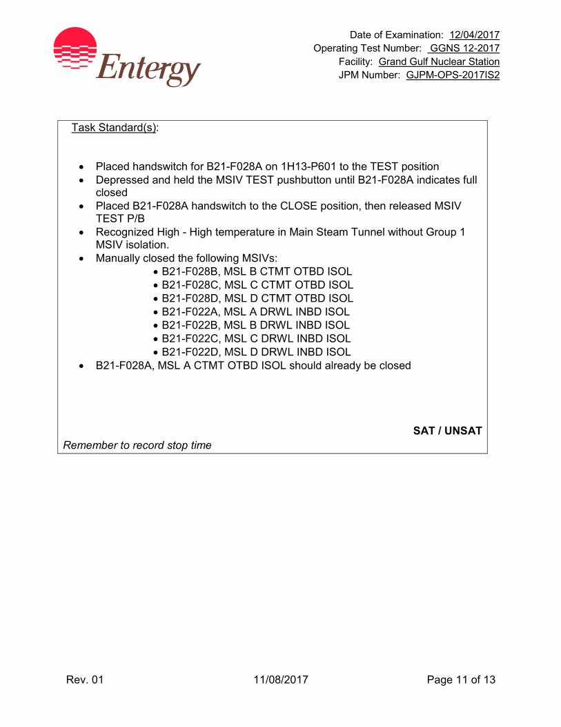
Date of Examination: 12/04/2017 Operating Test Number: GGNS 12-2017
Facility: Grand Gulf Nuclear Station JPM Number: GJPM-OPS-2017IS2
Rev. 01 11/08/2017 Page 11 of 13
Task Standard(s):
• Placed handswitch for B21-F028A on 1H13-P601 to the TEST position • Depressed and held the MSIV TEST pushbutton until B21-F028A indicates full
closed • Placed B21-F028A handswitch to the CLOSE position, then released MSIV
TEST P/B • Recognized High - High temperature in Main Steam Tunnel without Group 1
MSIV isolation. • Manually closed the following MSIVs:
• B21-F028B, MSL B CTMT OTBD ISOL • B21-F028C, MSL C CTMT OTBD ISOL • B21-F028D, MSL D CTMT OTBD ISOL • B21-F022A, MSL A DRWL INBD ISOL • B21-F022B, MSL B DRWL INBD ISOL • B21-F022C, MSL C DRWL INBD ISOL • B21-F022D, MSL D DRWL INBD ISOL
• B21-F028A, MSL A CTMT OTBD ISOL should already be closed
SAT / UNSAT
Remember to record stop time
Date of Examination: 12/04/2017 Operating Test Number: GGNS 12-2017
Facility: Grand Gulf Nuclear Station JPM Number: GJPM-OPS-2017IS2
Rev. 01 11/08/2017 Page 12 of 13
Follow-Up Questions & Answers:
Comments:
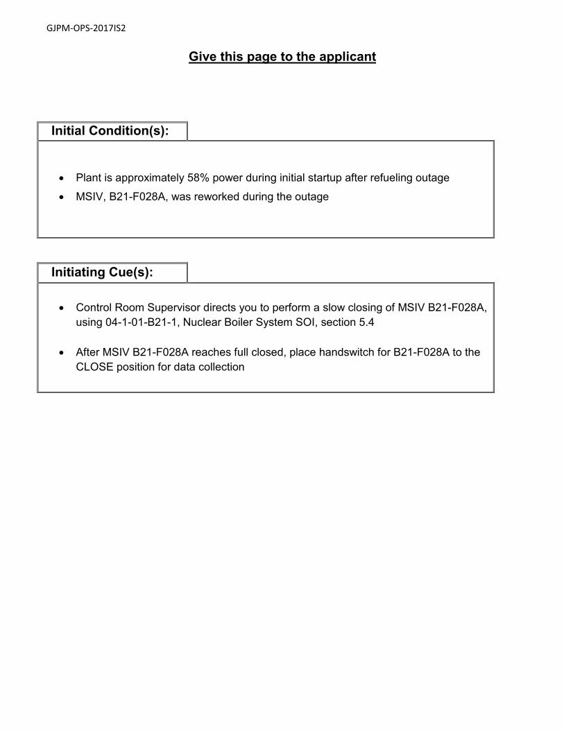
GJPM-OPS-2017IS2
Give this page to the applicant
Initial Condition(s):
• Plant is approximately 58% power during initial startup after refueling outage
• MSIV, B21-F028A, was reworked during the outage
Initiating Cue(s):
• Control Room Supervisor directs you to perform a slow closing of MSIV B21-F028A, using 04-1-01-B21-1, Nuclear Boiler System SOI, section 5.4
• After MSIV B21-F028A reaches full closed, place handswitch for B21-F028A to the CLOSE position for data collection

Date of Examination: 12/04/2017 Operating Test Number: GGNS 12-2017
Facility: Grand Gulf Nuclear Station JPM Number: GJPM-OPS-2017IS3
Rev. 01 11/08/2017 Page 1 of 25
2017I S3
GGNS
2017 NRC Operating Test
Job Performance Measure JPM Number: GJPM-OPS-2017IS3 JPM Title: Startup RHR Shutdown Cooling Facility Number: _GJPM-OPS-E12081_________ (If Bank or Modified from Bank)
JPM Attributes:
New Modified Direct from bank
Time Critical Alternate Path Validation Time: 20 min
Prepared By: Michael Rasch 11/08/2017 Exam Developer Date
Ops Review: Robert Brinkman 11/08/2017 1st Validation by Ops Rep or Ops Validation Crew Date
Validated By: Benny White \ Chase Miller 11/08/2017 2nd Validation by Ops Validation Crew Date
Approved By: Ricky Liddell 11/08/2017 Project Lead or Exam Team Lead Date
Date of Examination: 12/04/2017 Operating Test Number: LOT 2017I Facility: Grand Gulf Nuclear Station JPM Number: GJPM-OPS-2017IS3
Rev. 01 11/08/2017 Page 2 of 25
Startup RHR Shutdown Cooling
Time Critical Alternate Path Validation Time: 20 Min
Setting: Simulator Type: RO/SRO Task: GGNS-CRO-E12-SU/SD-8 K&A: 205000 A2.10 (2.9/2.9); A3.01 (3.2/3.1);
A4.02 (3.6/3.5); A4.01 (3.7/3.7); A4.03 (3.6/3.5); A4.06 (3.8/3.7)A4.09 (3.1/3.1)
Generic 2.1.30 (4.4/4.0); 2.1.31 (4.6/4.3) Safety Function: 4 – Heat Removal from Reactor Core PRA Applicability: System Importance to Core Damage Frequency rank 3 10CFR 55.45(a) (3); (4); (5); (7) Performance: Perform Reference(s): 04-1-01-E12-2, Rev. 123, Shutdown Cooling and
Alternate Decay Heat Removal Operation 04-1-02-1H13-P601 20A-E6 Rev. 102 Alarm Response
Instructions 1H13-P601 EN-OP-115, Rev. 20, Conduct of Operations 02-S-01-27, Rev. 73, Operations Philosophy EN-OP-120, Rev. 1, Operator Fundamentals Program Handout(s): 04-1-01-E12-2 Precautions & Limitations; section 4.1
marked up to section 4.1.2 c (6) # Manipulations: 11 # Critical Steps: 8 Low Power: YES Emergency/Abnormal: YES RCA entry: No Engineered Safety Function: No

Date of Examination: 12/04/2017 Operating Test Number: GGNS 12-2017
Facility: Grand Gulf Nuclear Station JPM Number: GJPM-OPS-2017IS3
Rev. 01 11/08/2017 Page 3 of 25
Simulator Setup/Required Plant Conditions:
• Reset Simulator to IC-14 • Run Schedule File JPM * E12081 RHR A SDC STARTUP
OR
• Initialize the simulator to Reactor in Mode 4 < 200 degrees F • Insert Component Override on E12-F064A handswitch to OPEN
di_1e12m621aP601/20C RHR A MIN FLO TO SUPP on TRIGGER 1 • Secure the RHR Shutdown Cooling ‘A’ lineup. Leave the RHR ‘A’ Room Cooler
and Standby Service Water ‘A’ in operation through RHR Heat Exchanger • Valve Lineup
• E12-F008, F009, F006A, F064A, F024A, F053A and B21-F065A Closed • E12-F003A, F048A, F047A Open
• Markup SOI 04-1-01-E12-2 to Step 4.1.2c (6) • Place Danger tag on 1E12-F037A and 1E12-F037B handswitches • Place Caution tag on 1B21-F065A handswitch • Pull up on H13-P680 right side PDS Heatup/Cooldown graph
Safety Concerns:
None
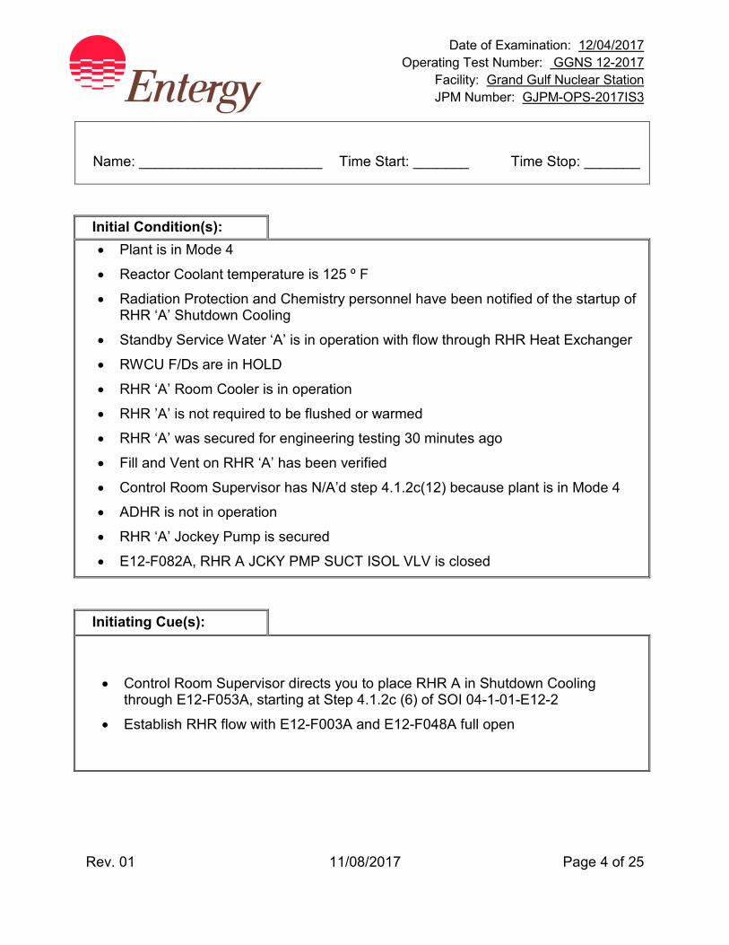
Date of Examination: 12/04/2017 Operating Test Number: GGNS 12-2017
Facility: Grand Gulf Nuclear Station JPM Number: GJPM-OPS-2017IS3
Rev. 01 11/08/2017 Page 4 of 25
Name: _______________________ Time Start: _______ Time Stop: _______
Initial Condition(s): • Plant is in Mode 4
• Reactor Coolant temperature is 125 º F
• Radiation Protection and Chemistry personnel have been notified of the startup of RHR ‘A’ Shutdown Cooling
• Standby Service Water ‘A’ is in operation with flow through RHR Heat Exchanger
• RWCU F/Ds are in HOLD
• RHR ‘A’ Room Cooler is in operation
• RHR ’A’ is not required to be flushed or warmed
• RHR ‘A’ was secured for engineering testing 30 minutes ago
• Fill and Vent on RHR ‘A’ has been verified
• Control Room Supervisor has N/A’d step 4.1.2c(12) because plant is in Mode 4
• ADHR is not in operation
• RHR ‘A’ Jockey Pump is secured
• E12-F082A, RHR A JCKY PMP SUCT ISOL VLV is closed
Initiating Cue(s):
• Control Room Supervisor directs you to place RHR A in Shutdown Cooling through E12-F053A, starting at Step 4.1.2c (6) of SOI 04-1-01-E12-2
• Establish RHR flow with E12-F003A and E12-F048A full open
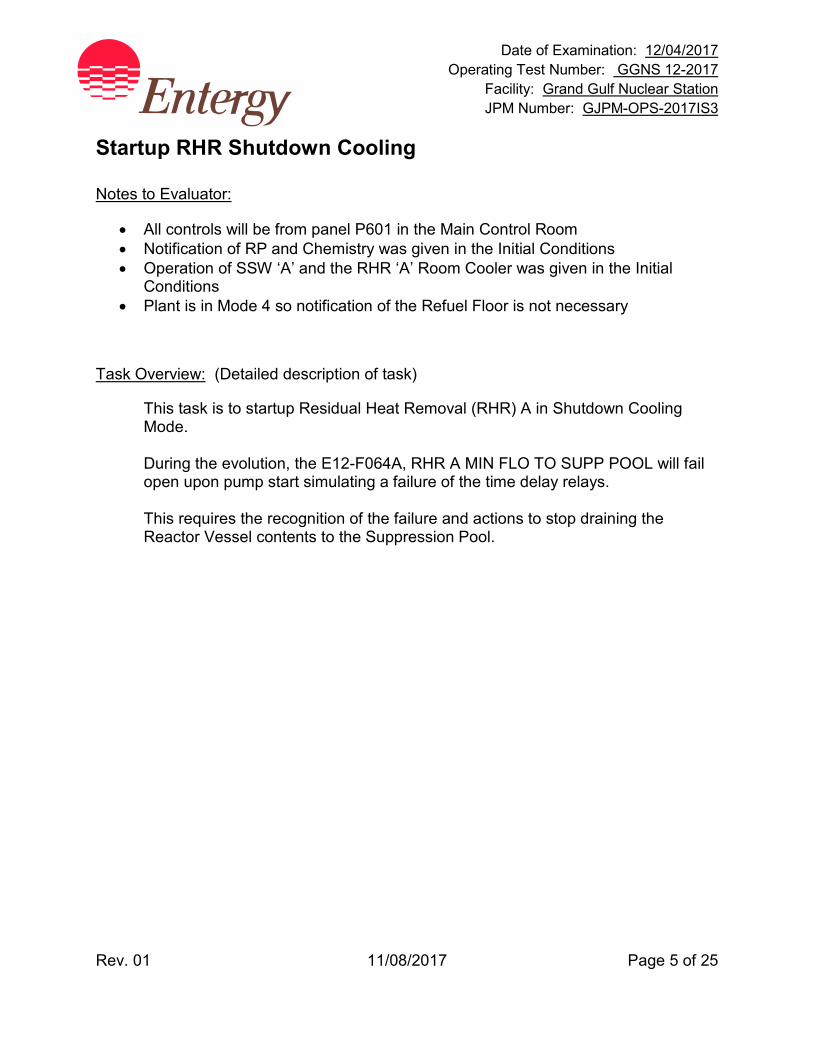
Date of Examination: 12/04/2017 Operating Test Number: GGNS 12-2017
Facility: Grand Gulf Nuclear Station JPM Number: GJPM-OPS-2017IS3
Rev. 01 11/08/2017 Page 5 of 25
Startup RHR Shutdown Cooling Notes to Evaluator:
• All controls will be from panel P601 in the Main Control Room • Notification of RP and Chemistry was given in the Initial Conditions • Operation of SSW ‘A’ and the RHR ‘A’ Room Cooler was given in the Initial
Conditions • Plant is in Mode 4 so notification of the Refuel Floor is not necessary
Task Overview: (Detailed description of task)
This task is to startup Residual Heat Removal (RHR) A in Shutdown Cooling Mode. During the evolution, the E12-F064A, RHR A MIN FLO TO SUPP POOL will fail open upon pump start simulating a failure of the time delay relays. This requires the recognition of the failure and actions to stop draining the Reactor Vessel contents to the Suppression Pool.
Date of Examination: 12/04/2017 Operating Test Number: GGNS 12-2017
Facility: Grand Gulf Nuclear Station JPM Number: GJPM-OPS-2017IS3
Rev. 01 11/08/2017 Page 6 of 25
Critical steps are underlined, italicized, and denoted by an (*) NOTE: The sequence of the following steps is critical unless otherwise noted.
Applicant may place MOV TEST switches to TEST just before operating MOVs. This is acceptable
Step 1: 04-1-01-E12-2, Step 3.8.18
PLACE RHR A MOV TEST handswitch to TEST
Standard: RHR A MOV TEST handswitch in TEST.
Annunciator 1H13-P601 20A-H6 RHR A SYS OOSVC will alarm and associated Status Light RHR A MOV IN TEST STATUS will illuminate
Cue: None
Notes: 1H13-P601 section 20B
Steps 1, 2 and 3 are NOT sequence critical.
SAT / UNSAT
Date of Examination: 12/04/2017 Operating Test Number: GGNS 12-2017
Facility: Grand Gulf Nuclear Station JPM Number: GJPM-OPS-2017IS3
Rev. 01 11/08/2017 Page 7 of 25
Step 2: 04-1-01-E12-2, Step 3.8.18
PLACE Division 1 NSSSS MOV TEST handswitch to TEST
Standard: Division 1 NSSSS MOV TEST handswitch in TEST.
Annunciator 1H13-P601 19A-H3, RX DIV1 ISOL-SYS-OOSVC alarms
Cue: None
Notes: 1H13-P601 section 19B is NSSSS OTBD MOV TEST (Division 1)
Steps 1, 2 and 3 are NOT sequence critical. SAT / UNSAT
Step 3: 04-1-01-E12-2, Step 3.8.18
PLACE Division 2 NSSSS MOV TEST handswitch to TEST
Standard: Division 2 NSSSS MOV TEST handswitch in TEST.
Annunciator 1H13-P601 19A-H3, RX DIV1 ISOL-SYS-OOSVC alarms
Cue: None
Notes: 1H13-P601 section 18B is NSSSS INBD MOV TEST (Division 2)
Steps 1, 2 and 3 are NOT sequence critical.
SAT / UNSAT
Date of Examination: 12/04/2017 Operating Test Number: GGNS 12-2017
Facility: Grand Gulf Nuclear Station JPM Number: GJPM-OPS-2017IS3
Rev. 01 11/08/2017 Page 8 of 25
Applicant reviews NOTE.
NOTE
To obtain good core circulation, it is recommended that AT LEAST ONE Recirculation pump be in operation. IF Recirculation Pumps are NOT in operation, reactor level is to be maintained above 82 inches. Step 4: 04-1-01-E12-2, Step 4.1.2c (6)
ENSURE CLOSED E12-F064A, RHR A MIN FLO TO SUPP POOL.
Standard: Checked closed E12-F064A, RHR A MIN FLO TO SUPP POOL by
observing valve position indication red light off, green light on.
Cue: None
Notes: 1H13-P601 section 20C
SAT / UNSAT
Date of Examination: 12/04/2017 Operating Test Number: GGNS 12-2017
Facility: Grand Gulf Nuclear Station JPM Number: GJPM-OPS-2017IS3
Rev. 01 11/08/2017 Page 9 of 25
Step 5: 04-1-01-E12-2, Step 4.1.2c (7)
ENSURE RHR JOCKEY PUMP A is shutdown.
Standard: Checked RHR Jockey Pump A is shutdown by either dispatching an
operator or going to the upper control room to secure the pump. Cue: Once applicant recognizes that the control switch for this pump is
located in the upper control room, CUE applicant that RHR A Jockey pump is secured.
Notes: RHR A Jockey Pump is not in the simulator. Applicant may recognize information given in cue
SAT / UNSAT
Step 6: 04-1-01-E12-2, Step 4.1.2c (8)
ENSURE CLOSED E12-F082A, RHR A JCKY PMP SUCT ISOL VLV.
Standard: Checked closed E12-F082A, RHR A JCKY PMP SUCT ISOL VLV by
either dispatching an operator or going to the upper control room and observing valve position indication.
Cue: Once applicant recognizes that the control switch for this valve is located in the upper control room, CUE applicant that E12-F082A, RHR A JCKY PMP SUCT ISOL VLV is closed.
Notes: Handswitch for the E12-F082A is not in the simulator. Applicant may recognize information given in cue
SAT / UNSAT
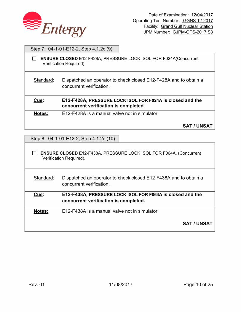
Date of Examination: 12/04/2017 Operating Test Number: GGNS 12-2017
Facility: Grand Gulf Nuclear Station JPM Number: GJPM-OPS-2017IS3
Rev. 01 11/08/2017 Page 10 of 25
Step 7: 04-1-01-E12-2, Step 4.1.2c (9)
ENSURE CLOSED E12-F428A, PRESSURE LOCK ISOL FOR F024A(Concurrent Verification Required)
Standard: Dispatched an operator to check closed E12-F428A and to obtain a concurrent verification.
Cue: E12-F428A, PRESSURE LOCK ISOL FOR F024A is closed and the concurrent verification is completed.
Notes: E12-F428A is a manual valve not in simulator.
SAT / UNSAT Step 8: 04-1-01-E12-2, Step 4.1.2c (10)
ENSURE CLOSED E12-F438A, PRESSURE LOCK ISOL FOR F064A. (Concurrent Verification Required).
Standard: Dispatched an operator to check closed E12-F438A and to obtain a
concurrent verification.
Cue: E12-F438A, PRESSURE LOCK ISOL FOR F064A is closed and the concurrent verification is completed.
Notes: E12-F438A is a manual valve not in simulator.
SAT / UNSAT

Date of Examination: 12/04/2017 Operating Test Number: GGNS 12-2017
Facility: Grand Gulf Nuclear Station JPM Number: GJPM-OPS-2017IS3
Rev. 01 11/08/2017 Page 11 of 25
Step 9: 04-1-01-E12-2, Step 4.1.2c (11)
ENSURE CLOSED E12-F004A, RHR A SUCT FM SUPP POOL.
Standard: Checked closed E12-F004A by observing valve position indication red
light off, green light on.
Cue: None
Notes: 1H13-P601 section 20C
SAT / UNSAT
Step 10: 04-1-01-E12-2, Step 4.1.2c (12)
IF Plant is in mode 5, THEN ENSURE the 135 psig pressure jumpers are installed per 03-1-01-5 to prevent inadvertent isolations. (This step May be N/A’d by an on-shift SRO.)
Standard: N/A
Cue: None
Notes: Per Initial Conditions, SRO N/A’d step. Plant is in Mode 4.
SAT / UNSAT
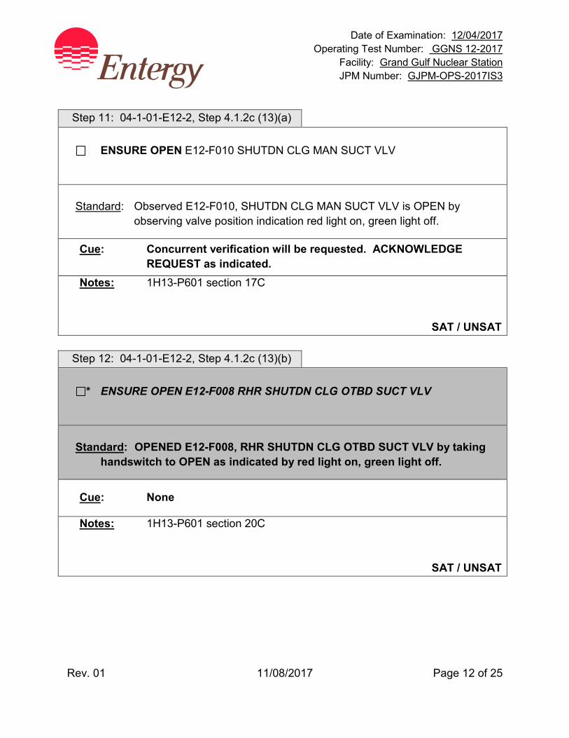
Date of Examination: 12/04/2017 Operating Test Number: GGNS 12-2017
Facility: Grand Gulf Nuclear Station JPM Number: GJPM-OPS-2017IS3
Rev. 01 11/08/2017 Page 12 of 25
Step 11: 04-1-01-E12-2, Step 4.1.2c (13)(a)
ENSURE OPEN E12-F010 SHUTDN CLG MAN SUCT VLV
Standard: Observed E12-F010, SHUTDN CLG MAN SUCT VLV is OPEN by
observing valve position indication red light on, green light off.
Cue: Concurrent verification will be requested. ACKNOWLEDGE REQUEST as indicated.
Notes: 1H13-P601 section 17C
SAT / UNSAT
Step 12: 04-1-01-E12-2, Step 4.1.2c (13)(b)
* ENSURE OPEN E12-F008 RHR SHUTDN CLG OTBD SUCT VLV
Standard: OPENED E12-F008, RHR SHUTDN CLG OTBD SUCT VLV by taking
handswitch to OPEN as indicated by red light on, green light off.
Cue: None
Notes: 1H13-P601 section 20C
SAT / UNSAT
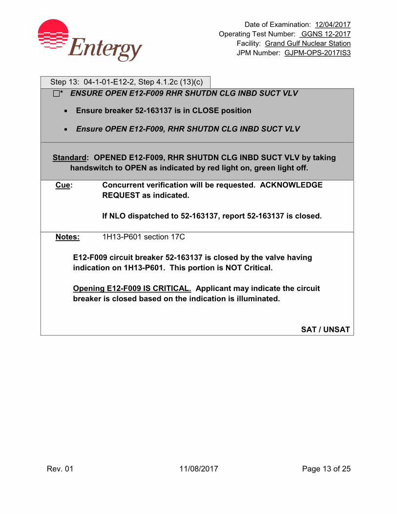
Date of Examination: 12/04/2017 Operating Test Number: GGNS 12-2017
Facility: Grand Gulf Nuclear Station JPM Number: GJPM-OPS-2017IS3
Rev. 01 11/08/2017 Page 13 of 25
Step 13: 04-1-01-E12-2, Step 4.1.2c (13)(c)
* ENSURE OPEN E12-F009 RHR SHUTDN CLG INBD SUCT VLV
• Ensure breaker 52-163137 is in CLOSE position
• Ensure OPEN E12-F009, RHR SHUTDN CLG INBD SUCT VLV
Standard: OPENED E12-F009, RHR SHUTDN CLG INBD SUCT VLV by taking
handswitch to OPEN as indicated by red light on, green light off.
Cue: Concurrent verification will be requested. ACKNOWLEDGE REQUEST as indicated.
If NLO dispatched to 52-163137, report 52-163137 is closed. Notes: 1H13-P601 section 17C
E12-F009 circuit breaker 52-163137 is closed by the valve having indication on 1H13-P601. This portion is NOT Critical. Opening E12-F009 IS CRITICAL. Applicant may indicate the circuit breaker is closed based on the indication is illuminated.
SAT / UNSAT
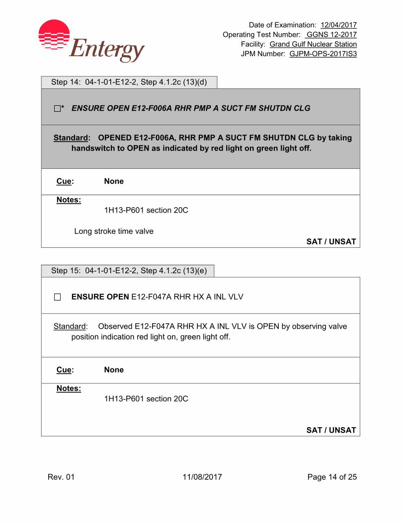
Date of Examination: 12/04/2017 Operating Test Number: GGNS 12-2017
Facility: Grand Gulf Nuclear Station JPM Number: GJPM-OPS-2017IS3
Rev. 01 11/08/2017 Page 14 of 25
Step 14: 04-1-01-E12-2, Step 4.1.2c (13)(d)
* ENSURE OPEN E12-F006A RHR PMP A SUCT FM SHUTDN CLG
Standard: OPENED E12-F006A, RHR PMP A SUCT FM SHUTDN CLG by taking handswitch to OPEN as indicated by red light on green light off.
Cue: None
Notes: 1H13-P601 section 20C
Long stroke time valve SAT / UNSAT
Step 15: 04-1-01-E12-2, Step 4.1.2c (13)(e)
ENSURE OPEN E12-F047A RHR HX A INL VLV
Standard: Observed E12-F047A RHR HX A INL VLV is OPEN by observing valve position indication red light on, green light off.
Cue: None
Notes: 1H13-P601 section 20C
SAT / UNSAT
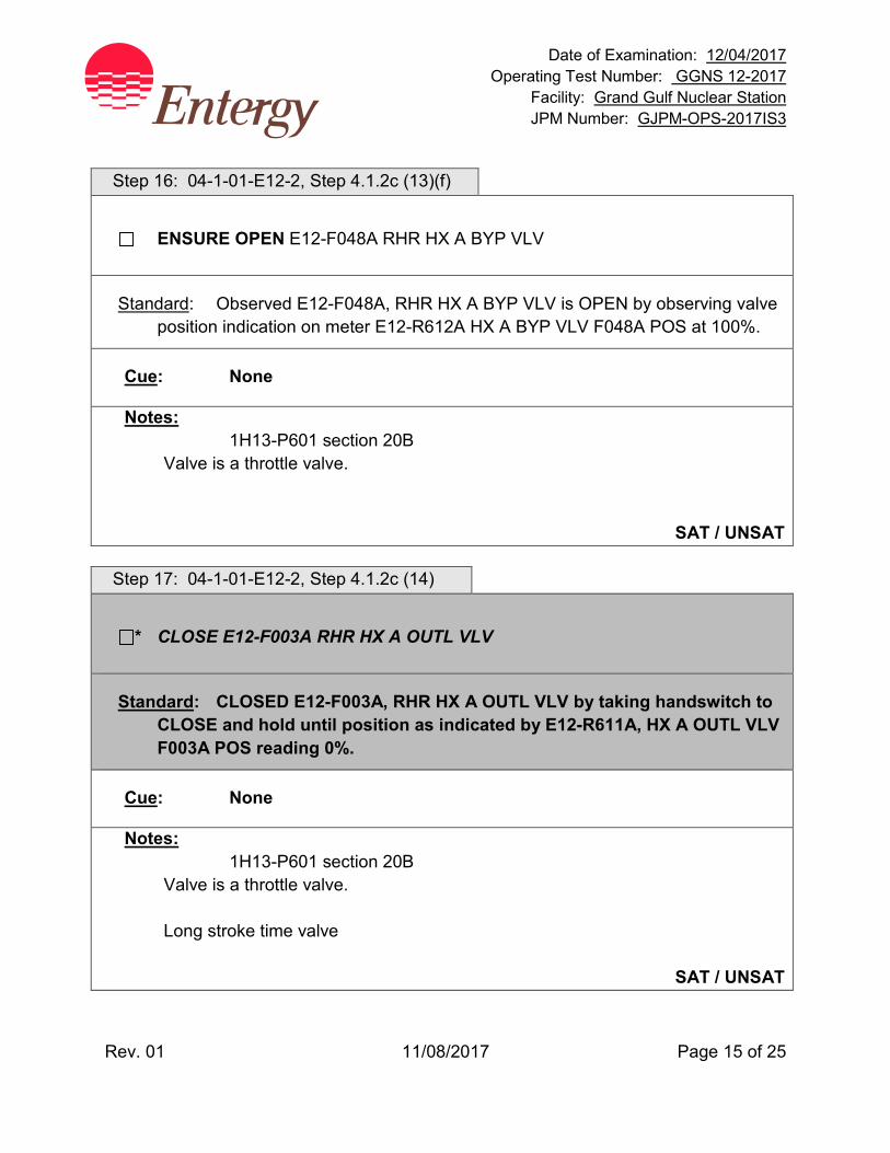
Date of Examination: 12/04/2017 Operating Test Number: GGNS 12-2017
Facility: Grand Gulf Nuclear Station JPM Number: GJPM-OPS-2017IS3
Rev. 01 11/08/2017 Page 15 of 25
Step 16: 04-1-01-E12-2, Step 4.1.2c (13)(f)
ENSURE OPEN E12-F048A RHR HX A BYP VLV
Standard: Observed E12-F048A, RHR HX A BYP VLV is OPEN by observing valve position indication on meter E12-R612A HX A BYP VLV F048A POS at 100%.
Cue: None
Notes: 1H13-P601 section 20B
Valve is a throttle valve.
SAT / UNSAT Step 17: 04-1-01-E12-2, Step 4.1.2c (14)
* CLOSE E12-F003A RHR HX A OUTL VLV
Standard: CLOSED E12-F003A, RHR HX A OUTL VLV by taking handswitch to CLOSE and hold until position as indicated by E12-R611A, HX A OUTL VLV F003A POS reading 0%.
Cue: None
Notes: 1H13-P601 section 20B
Valve is a throttle valve. Long stroke time valve
SAT / UNSAT
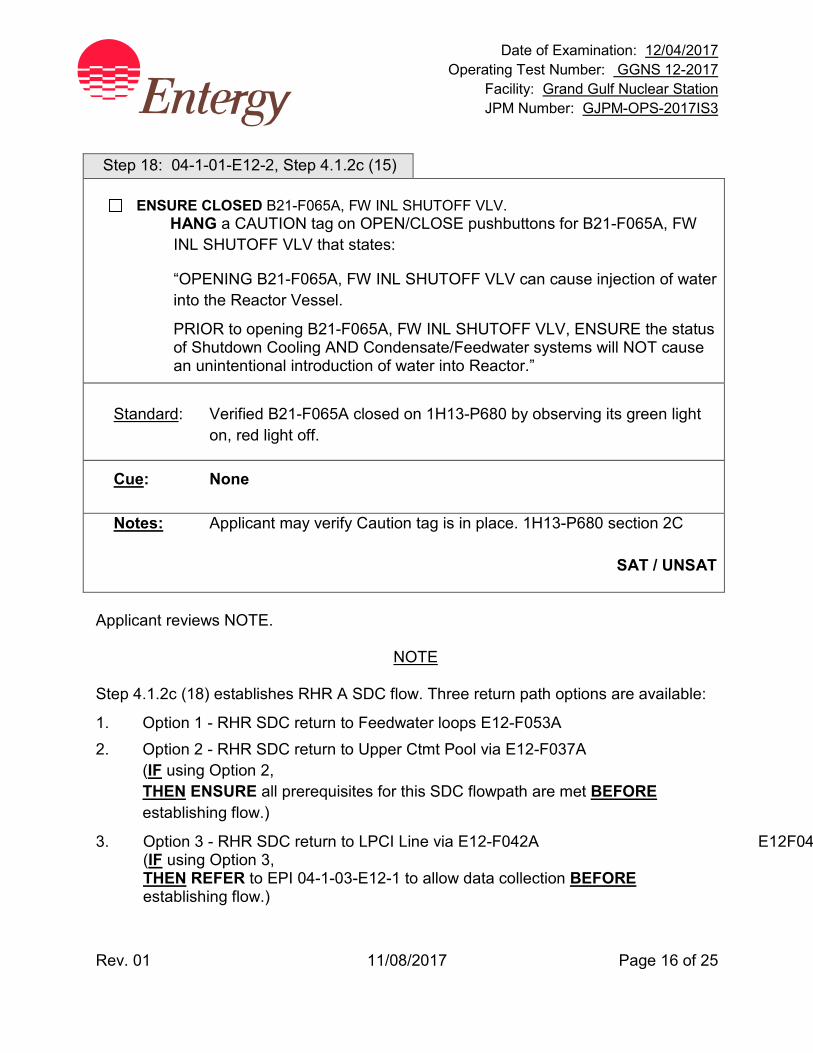
Date of Examination: 12/04/2017 Operating Test Number: GGNS 12-2017
Facility: Grand Gulf Nuclear Station JPM Number: GJPM-OPS-2017IS3
Rev. 01 11/08/2017 Page 16 of 25
Step 18: 04-1-01-E12-2, Step 4.1.2c (15)
ENSURE CLOSED B21-F065A, FW INL SHUTOFF VLV. HANG a CAUTION tag on OPEN/CLOSE pushbuttons for B21-F065A, FW INL SHUTOFF VLV that states:
“OPENING B21-F065A, FW INL SHUTOFF VLV can cause injection of water into the Reactor Vessel.
PRIOR to opening B21-F065A, FW INL SHUTOFF VLV, ENSURE the status of Shutdown Cooling AND Condensate/Feedwater systems will NOT cause an unintentional introduction of water into Reactor.”
Standard: Verified B21-F065A closed on 1H13-P680 by observing its green light
on, red light off.
Cue: None
Notes: Applicant may verify Caution tag is in place. 1H13-P680 section 2C
SAT / UNSAT
Applicant reviews NOTE.
NOTE
Step 4.1.2c (18) establishes RHR A SDC flow. Three return path options are available:
1. Option 1 - RHR SDC return to Feedwater loops E12-F053A 2. Option 2 - RHR SDC return to Upper Ctmt Pool via E12-F037A
(IF using Option 2, THEN ENSURE all prerequisites for this SDC flowpath are met BEFORE establishing flow.)
3. Option 3 - RHR SDC return to LPCI Line via E12-F042A E12F04 (IF using Option 3, THEN REFER to EPI 04-1-03-E12-1 to allow data collection BEFORE establishing flow.)
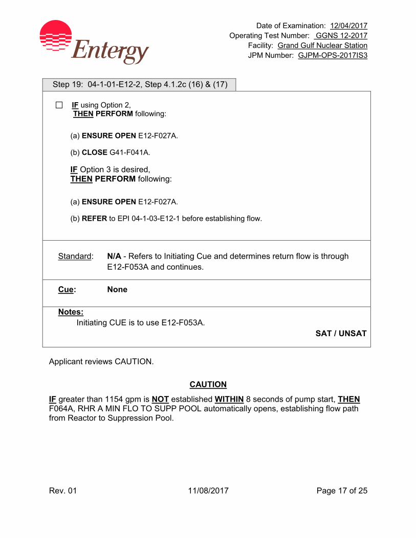
Date of Examination: 12/04/2017 Operating Test Number: GGNS 12-2017
Facility: Grand Gulf Nuclear Station JPM Number: GJPM-OPS-2017IS3
Rev. 01 11/08/2017 Page 17 of 25
Step 19: 04-1-01-E12-2, Step 4.1.2c (16) & (17)
IF using Option 2, THEN PERFORM following:
(a) ENSURE OPEN E12-F027A.
(b) CLOSE G41-F041A.
IF Option 3 is desired, THEN PERFORM following:
(a) ENSURE OPEN E12-F027A.
(b) REFER to EPI 04-1-03-E12-1 before establishing flow.
Standard: N/A - Refers to Initiating Cue and determines return flow is through
E12-F053A and continues.
Cue: None
Notes: Initiating CUE is to use E12-F053A.
SAT / UNSAT
Applicant reviews CAUTION.
CAUTION
IF greater than 1154 gpm is NOT established WITHIN 8 seconds of pump start, THEN F064A, RHR A MIN FLO TO SUPP POOL automatically opens, establishing flow path from Reactor to Suppression Pool.
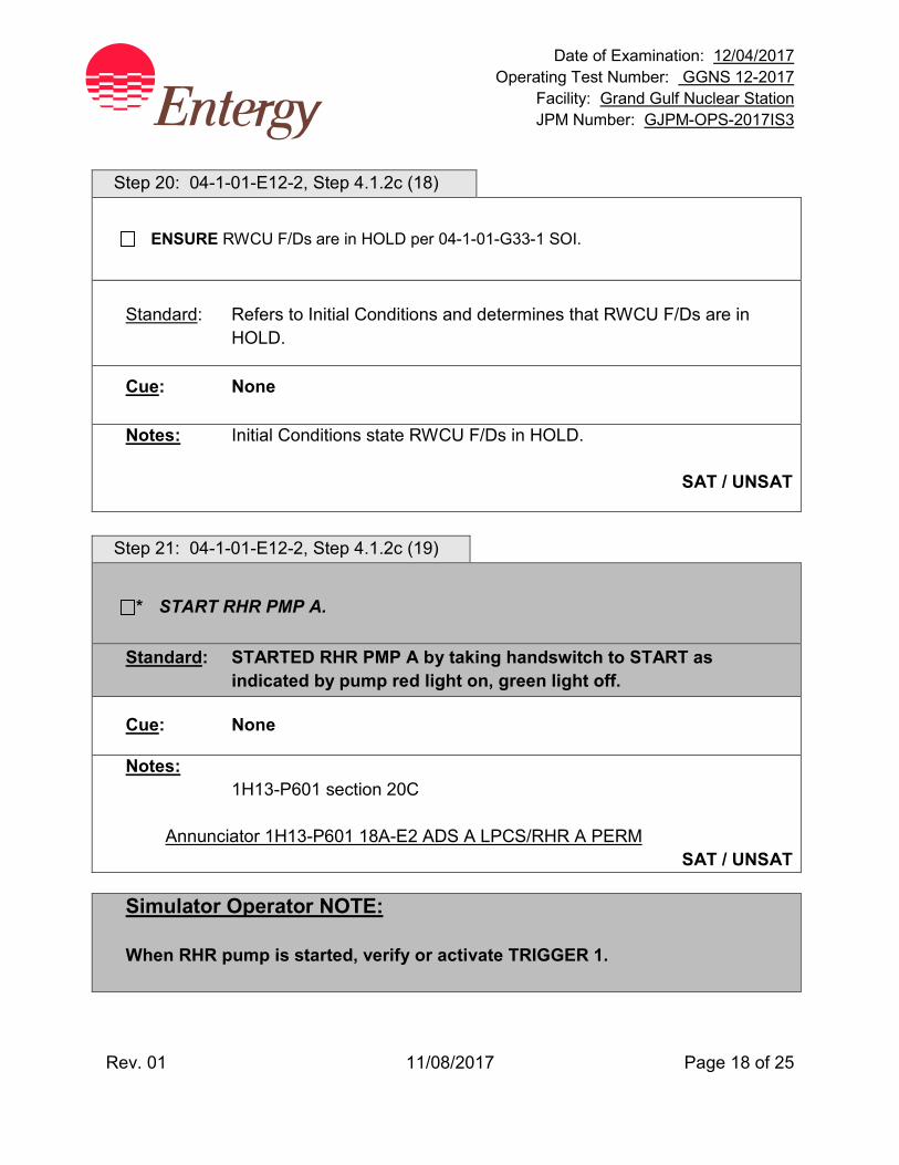
Date of Examination: 12/04/2017 Operating Test Number: GGNS 12-2017
Facility: Grand Gulf Nuclear Station JPM Number: GJPM-OPS-2017IS3
Rev. 01 11/08/2017 Page 18 of 25
Step 20: 04-1-01-E12-2, Step 4.1.2c (18)
ENSURE RWCU F/Ds are in HOLD per 04-1-01-G33-1 SOI.
Standard: Refers to Initial Conditions and determines that RWCU F/Ds are in
HOLD.
Cue: None
Notes: Initial Conditions state RWCU F/Ds in HOLD.
SAT / UNSAT
Step 21: 04-1-01-E12-2, Step 4.1.2c (19)
* START RHR PMP A.
Standard: STARTED RHR PMP A by taking handswitch to START as indicated by pump red light on, green light off.
Cue: None
Notes: 1H13-P601 section 20C
Annunciator 1H13-P601 18A-E2 ADS A LPCS/RHR A PERM SAT / UNSAT
Simulator Operator NOTE: When RHR pump is started, verify or activate TRIGGER 1.
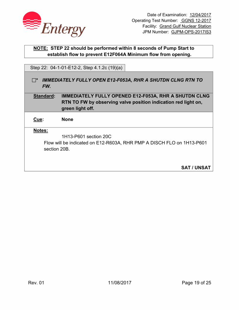
Date of Examination: 12/04/2017 Operating Test Number: GGNS 12-2017
Facility: Grand Gulf Nuclear Station JPM Number: GJPM-OPS-2017IS3
Rev. 01 11/08/2017 Page 19 of 25
NOTE: STEP 22 should be performed within 8 seconds of Pump Start to
establish flow to prevent E12F064A Minimum flow from opening. Step 22: 04-1-01-E12-2, Step 4.1.2c (19)(a)
* IMMEDIATELY FULLY OPEN E12-F053A, RHR A SHUTDN CLNG RTN TO FW.
Standard: IMMEDIATELY FULLY OPENED E12-F053A, RHR A SHUTDN CLNG RTN TO FW by observing valve position indication red light on, green light off.
Cue: None
Notes: 1H13-P601 section 20C
Flow will be indicated on E12-R603A, RHR PMP A DISCH FLO on 1H13-P601 section 20B.
SAT / UNSAT
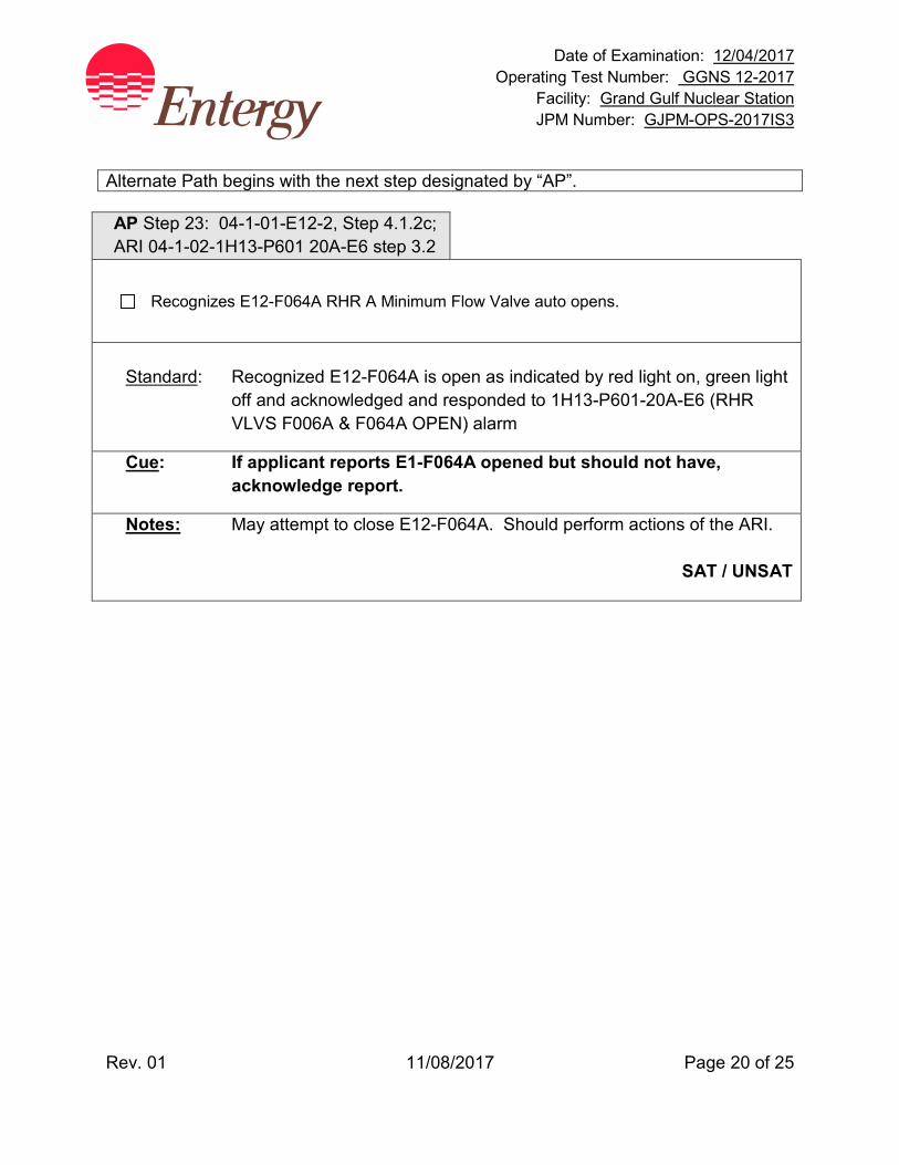
Date of Examination: 12/04/2017 Operating Test Number: GGNS 12-2017
Facility: Grand Gulf Nuclear Station JPM Number: GJPM-OPS-2017IS3
Rev. 01 11/08/2017 Page 20 of 25
Alternate Path begins with the next step designated by “AP”. AP Step 23: 04-1-01-E12-2, Step 4.1.2c; ARI 04-1-02-1H13-P601 20A-E6 step 3.2
Recognizes E12-F064A RHR A Minimum Flow Valve auto opens.
Standard: Recognized E12-F064A is open as indicated by red light on, green light
off and acknowledged and responded to 1H13-P601-20A-E6 (RHR VLVS F006A & F064A OPEN) alarm
Cue: If applicant reports E1-F064A opened but should not have, acknowledge report.
Notes: May attempt to close E12-F064A. Should perform actions of the ARI.
SAT / UNSAT
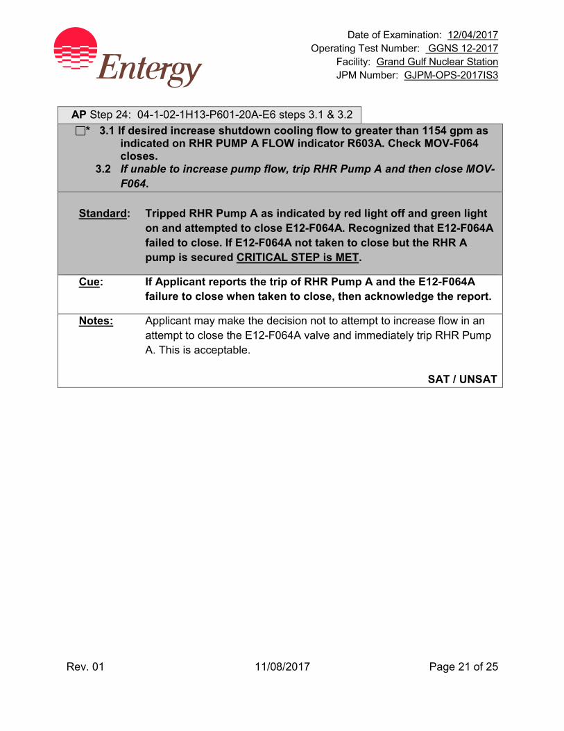
Date of Examination: 12/04/2017 Operating Test Number: GGNS 12-2017
Facility: Grand Gulf Nuclear Station JPM Number: GJPM-OPS-2017IS3
Rev. 01 11/08/2017 Page 21 of 25
AP Step 24: 04-1-02-1H13-P601-20A-E6 steps 3.1 & 3.2
* 3.1 If desired increase shutdown cooling flow to greater than 1154 gpm as indicated on RHR PUMP A FLOW indicator R603A. Check MOV-F064 closes.
3.2 If unable to increase pump flow, trip RHR Pump A and then close MOV-F064.
Standard: Tripped RHR Pump A as indicated by red light off and green light
on and attempted to close E12-F064A. Recognized that E12-F064A failed to close. If E12-F064A not taken to close but the RHR A pump is secured CRITICAL STEP is MET.
Cue: If Applicant reports the trip of RHR Pump A and the E12-F064A failure to close when taken to close, then acknowledge the report.
Notes: Applicant may make the decision not to attempt to increase flow in an attempt to close the E12-F064A valve and immediately trip RHR Pump A. This is acceptable.
SAT / UNSAT

Date of Examination: 12/04/2017 Operating Test Number: GGNS 12-2017
Facility: Grand Gulf Nuclear Station JPM Number: GJPM-OPS-2017IS3
Rev. 01 11/08/2017 Page 22 of 25
AP Step 25: EN-OP-115 step 4.0[2](b) and 02-S-01-27 step 6.7.15.1
* CLOSES any or all of the following valves: a) E12-F006A b) E12-F008 c) E12-F009
Standard: Closed any or all of the following valves:
E12-F006A, RHR PMP A SUCT FM SHUTDN CLG
E12-F008, RHR SHUTDN CLG OTBD SUCT VLV
E12-F009, RHR SHUTDN CLG INBD SUCT VLV
by turning their handswitches to CLOSE and observing their red lights are off and their green lights are on.
Cue: None
Notes: Closing any one or all three valves will still satisfy the task. EVALUATOR TERMINATE JPM after RHR A pump is secured and any one of the above valves have been closed.
SAT / UNSAT
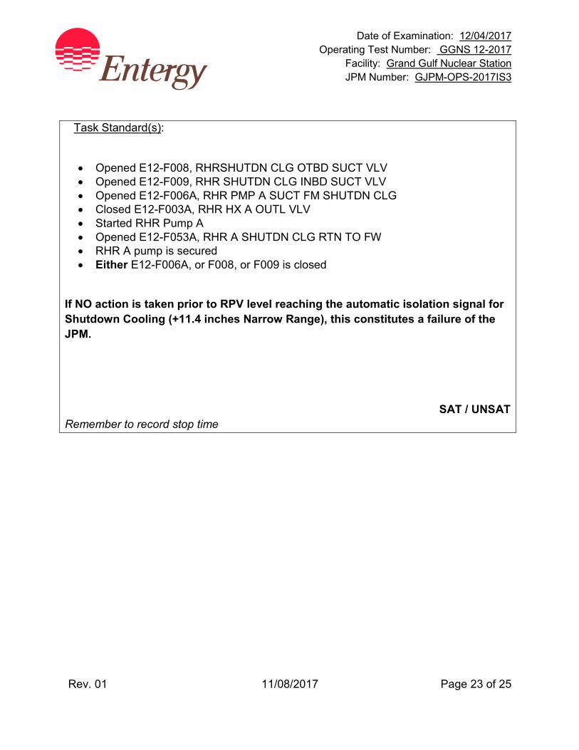
Date of Examination: 12/04/2017 Operating Test Number: GGNS 12-2017
Facility: Grand Gulf Nuclear Station JPM Number: GJPM-OPS-2017IS3
Rev. 01 11/08/2017 Page 23 of 25
Task Standard(s):
• Opened E12-F008, RHRSHUTDN CLG OTBD SUCT VLV • Opened E12-F009, RHR SHUTDN CLG INBD SUCT VLV • Opened E12-F006A, RHR PMP A SUCT FM SHUTDN CLG • Closed E12-F003A, RHR HX A OUTL VLV • Started RHR Pump A • Opened E12-F053A, RHR A SHUTDN CLG RTN TO FW • RHR A pump is secured • Either E12-F006A, or F008, or F009 is closed
If NO action is taken prior to RPV level reaching the automatic isolation signal for Shutdown Cooling (+11.4 inches Narrow Range), this constitutes a failure of the JPM.
SAT / UNSAT Remember to record stop time

Date of Examination: 12/04/2017 Operating Test Number: GGNS 12-2017
Facility: Grand Gulf Nuclear Station JPM Number: GJPM-OPS-2017IS3
Rev. 01 11/08/2017 Page 24 of 25
Follow-Up Questions & Answers:
Comments:
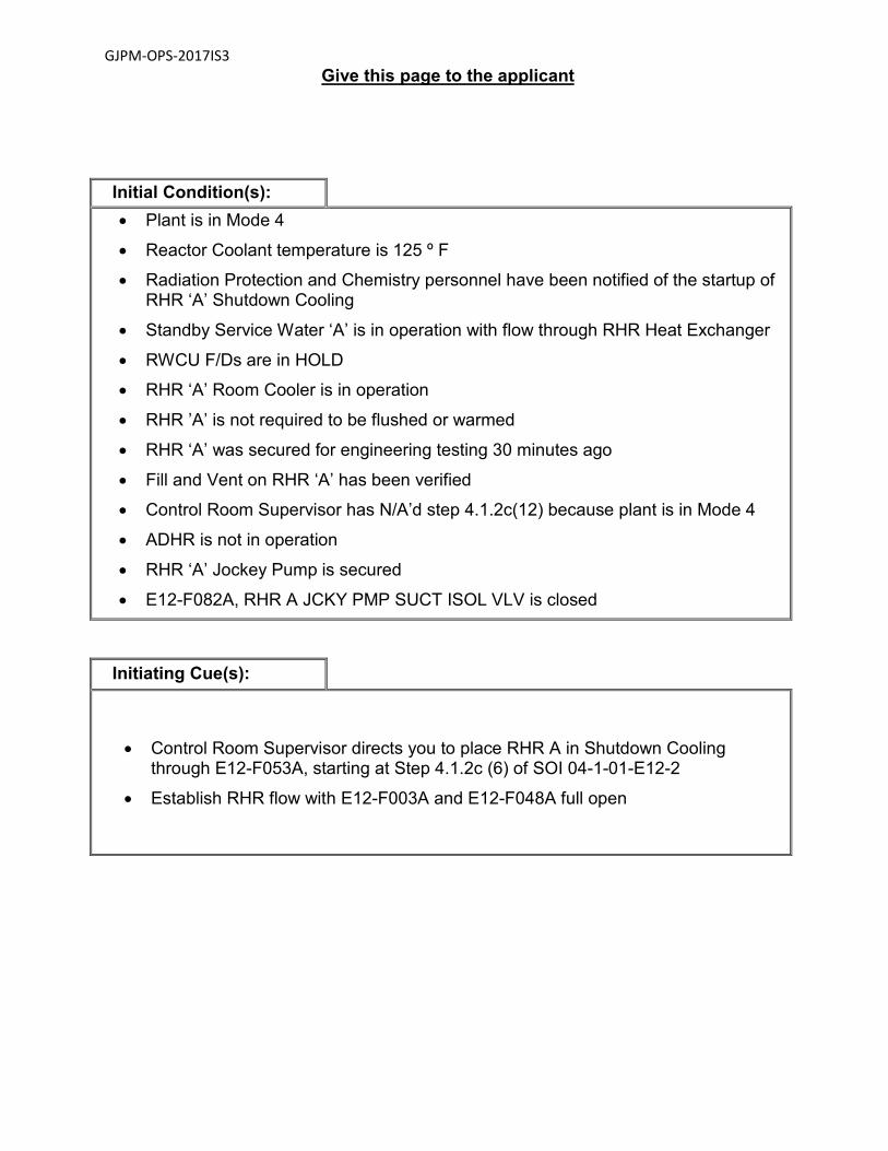
GJPM-OPS-2017IS3
Give this page to the applicant
Initial Condition(s): • Plant is in Mode 4
• Reactor Coolant temperature is 125 º F
• Radiation Protection and Chemistry personnel have been notified of the startup of RHR ‘A’ Shutdown Cooling
• Standby Service Water ‘A’ is in operation with flow through RHR Heat Exchanger
• RWCU F/Ds are in HOLD
• RHR ‘A’ Room Cooler is in operation
• RHR ’A’ is not required to be flushed or warmed
• RHR ‘A’ was secured for engineering testing 30 minutes ago
• Fill and Vent on RHR ‘A’ has been verified
• Control Room Supervisor has N/A’d step 4.1.2c(12) because plant is in Mode 4
• ADHR is not in operation
• RHR ‘A’ Jockey Pump is secured
• E12-F082A, RHR A JCKY PMP SUCT ISOL VLV is closed
Initiating Cue(s):
• Control Room Supervisor directs you to place RHR A in Shutdown Cooling through E12-F053A, starting at Step 4.1.2c (6) of SOI 04-1-01-E12-2
• Establish RHR flow with E12-F003A and E12-F048A full open
Date of Examination: 12/04/2017 Operating Test Number: GGNS 12-2017
Facility: Grand Gulf Nuclear Station JPM Number: GJPM-OPS-2017IS4
Rev. 03 12/01/2017 Page 1 of 25
2017I S4
GGNS
2017 NRC Operating Test
Job Performance Measure JPM Number: GJPM-OPS-2017IS4 JPM Title: Start, Parallel and Load EDG Facility Number: _GJPM-OPS-P75021_________ (If Bank or Modified from Bank)
JPM Attributes:
New Modified Direct from bank
Time Critical Alternate Path Validation Time: 25 min
Prepared By: Michael Rasch 11/09/2017 Exam Developer Date
Ops Review: Robert Brinkman 11/09/2017 1st Validation by Ops Rep or Ops Validation Crew Date
Validated By: Benny White \ Chase Miller 11/09/2017 2nd Validation by Ops Validation Crew Date
Approved By: Ricky Liddell 11/09/2017 Project Lead or Exam Team Lead Date
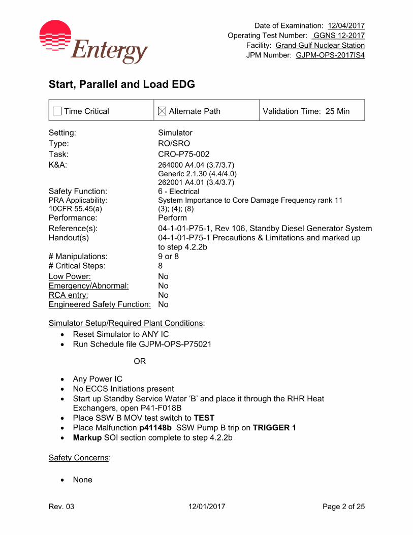
Date of Examination: 12/04/2017 Operating Test Number: GGNS 12-2017
Facility: Grand Gulf Nuclear Station JPM Number: GJPM-OPS-2017IS4
Rev. 03 12/01/2017 Page 2 of 25
Start, Parallel and Load EDG
Time Critical Alternate Path Validation Time: 25 Min
Setting: Simulator Type: RO/SRO Task: CRO-P75-002 K&A: 264000 A4.04 (3.7/3.7) Generic 2.1.30 (4.4/4.0) 262001 A4.01 (3.4/3.7) Safety Function: 6 - Electrical PRA Applicability: System Importance to Core Damage Frequency rank 11 10CFR 55.45(a) (3); (4); (8) Performance: Perform Reference(s): 04-1-01-P75-1, Rev 106, Standby Diesel Generator System Handout(s) 04-1-01-P75-1 Precautions & Limitations and marked up
to step 4.2.2b # Manipulations: 9 or 8 # Critical Steps: 8 Low Power: No Emergency/Abnormal: No RCA entry: No Engineered Safety Function: No Simulator Setup/Required Plant Conditions:
• Reset Simulator to ANY IC • Run Schedule file GJPM-OPS-P75021
OR
• Any Power IC • No ECCS Initiations present • Start up Standby Service Water ‘B’ and place it through the RHR Heat
Exchangers, open P41-F018B • Place SSW B MOV test switch to TEST • Place Malfunction p41148b SSW Pump B trip on TRIGGER 1 • Markup SOI section complete to step 4.2.2b
Safety Concerns:
• None
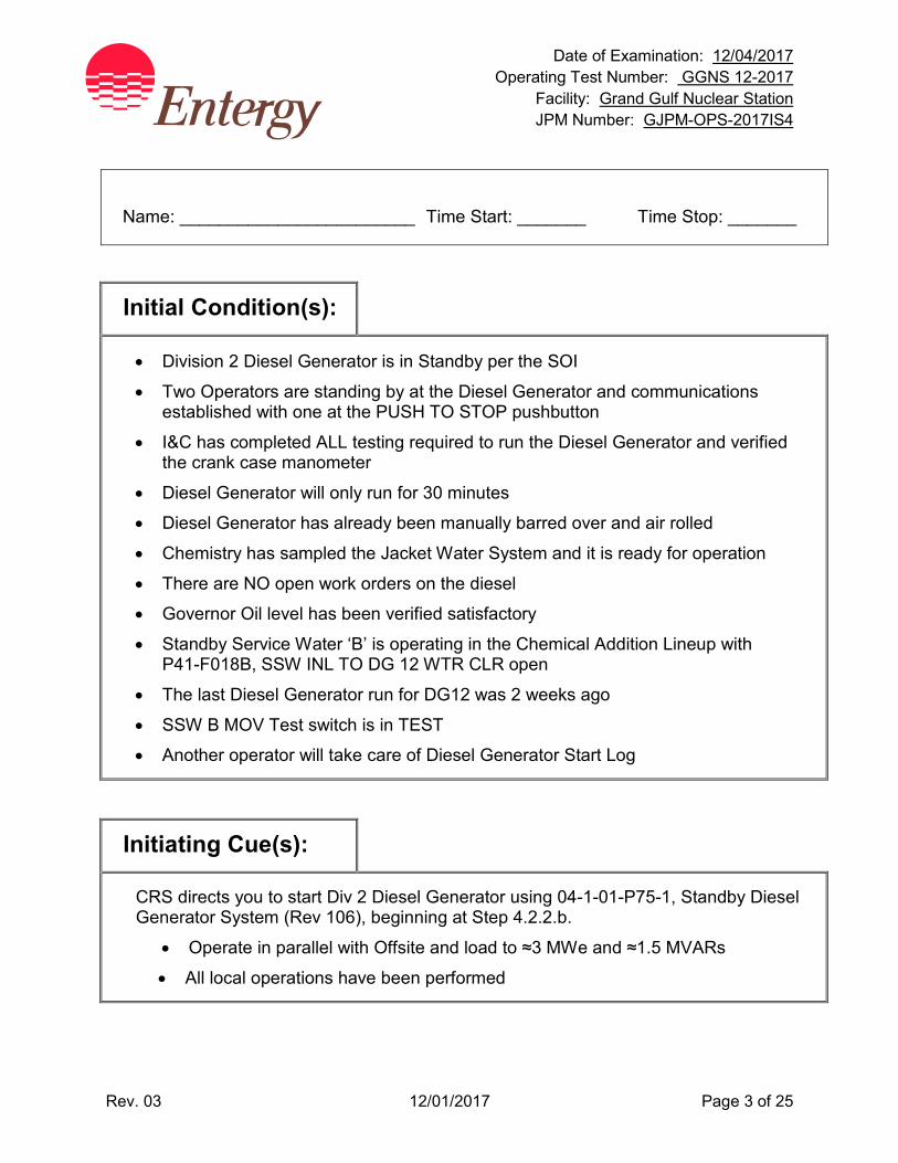
Date of Examination: 12/04/2017 Operating Test Number: GGNS 12-2017
Facility: Grand Gulf Nuclear Station JPM Number: GJPM-OPS-2017IS4
Rev. 03 12/01/2017 Page 3 of 25
Name: ________________________ Time Start: _______ Time Stop: _______
Initial Condition(s):
• Division 2 Diesel Generator is in Standby per the SOI
• Two Operators are standing by at the Diesel Generator and communications established with one at the PUSH TO STOP pushbutton
• I&C has completed ALL testing required to run the Diesel Generator and verified the crank case manometer
• Diesel Generator will only run for 30 minutes
• Diesel Generator has already been manually barred over and air rolled
• Chemistry has sampled the Jacket Water System and it is ready for operation
• There are NO open work orders on the diesel
• Governor Oil level has been verified satisfactory
• Standby Service Water ‘B’ is operating in the Chemical Addition Lineup with P41-F018B, SSW INL TO DG 12 WTR CLR open
• The last Diesel Generator run for DG12 was 2 weeks ago
• SSW B MOV Test switch is in TEST
• Another operator will take care of Diesel Generator Start Log
Initiating Cue(s):
CRS directs you to start Div 2 Diesel Generator using 04-1-01-P75-1, Standby Diesel Generator System (Rev 106), beginning at Step 4.2.2.b.
• Operate in parallel with Offsite and load to ≈3 MWe and ≈1.5 MVARs
• All local operations have been performed
Date of Examination: 12/04/2017 Operating Test Number: GGNS 12-2017
Facility: Grand Gulf Nuclear Station JPM Number: GJPM-OPS-2017IS4
Rev. 03 12/01/2017 Page 4 of 25
Start, Parallel and Load EDG Notes to Evaluator:
• All controls will be from panel P864 in the Main Control Room Task Overview: (Detailed description of task)
This task is to start the Division 2 Standby Diesel Generator (DG12), parallel the generator to 16AB bus and load the generator with real and reactive load per the SOI. With the Diesel connected to the bus loaded, Standby Service Water will be lost requiring the applicant to secure the Diesel Generator in accordance with Precaution and Limitation 3.55, CAUTION prior to Step 4.2.2.c and Step 4.2.2 c (6).

Date of Examination: 12/04/2017 Operating Test Number: GGNS 12-2017
Facility: Grand Gulf Nuclear Station JPM Number: GJPM-OPS-2017IS4
Rev. 03 12/01/2017 Page 5 of 25
Critical steps are shaded, bolded, italicized, and denoted by an (*) NOTE: The sequence of the following steps is critical unless otherwise noted.
Step 1: 04-1-01-P75-1, Step 4.2.2 b (1)
On Local Pump Control panel START Auxiliary Lube Oil pump C007B by PLACING its Control switch HS-M031B to CLOSE AND THEN BACK to AUTO. After Turbo Oil Press Left Front R014B gage AND Turbo Oil Press Right Front R015B gage increase to ≥20 psig for Div 2, STOP Auxiliary Lube Oil pump by PLACING Control switch HS-M031B to TRIP AND THEN BACK to AUTO.
Standard: Applicant instructed local operator to start Auxiliary Lube Oil Pump and return control to AUTO. Then, after Turbo Oil Press Left and Right is > 20 psig, instructed local operator to stop Auxiliary Lube Oil Pump.
Cue: Left and Right Turbo Oil Pressures are 25 psig and the Auxiliary Lube Oil Pump is stopped and in AUTO.
Notes: None
SAT / UNSAT
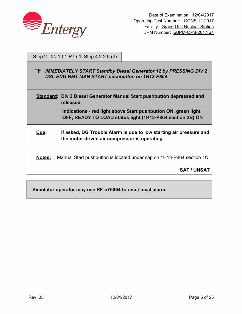
Date of Examination: 12/04/2017 Operating Test Number: GGNS 12-2017
Facility: Grand Gulf Nuclear Station JPM Number: GJPM-OPS-2017IS4
Rev. 03 12/01/2017 Page 6 of 25
Step 2: 04-1-01-P75-1, Step 4.2.2 b (2)
* IMMEDIATELY START Standby Diesel Generator 12 by PRESSING DIV 2 DSL ENG RMT MAN START pushbutton on 1H13-P864
Standard: Div 2 Diesel Generator Manual Start pushbutton depressed and released.
Indications - red light above Start pushbutton ON, green light OFF, READY TO LOAD status light (1H13-P864 section 2B) ON
Cue: If asked, DG Trouble Alarm is due to low starting air pressure and the motor driven air compressor is operating.
Notes: Manual Start pushbutton is located under cap on 1H13-P864 section 1C
SAT / UNSAT
Simulator operator may use RF-p75064 to reset local alarm.
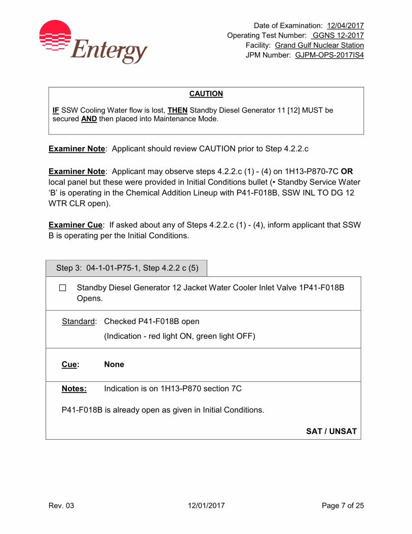
Date of Examination: 12/04/2017 Operating Test Number: GGNS 12-2017
Facility: Grand Gulf Nuclear Station JPM Number: GJPM-OPS-2017IS4
Rev. 03 12/01/2017 Page 7 of 25
CAUTION
IF SSW Cooling Water flow is lost, THEN Standby Diesel Generator 11 [12] MUST be secured AND then placed into Maintenance Mode.
Examiner Note: Applicant should review CAUTION prior to Step 4.2.2.c Examiner Note: Applicant may observe steps 4.2.2.c (1) - (4) on 1H13-P870-7C OR local panel but these were provided in Initial Conditions bullet (• Standby Service Water ‘B’ is operating in the Chemical Addition Lineup with P41-F018B, SSW INL TO DG 12 WTR CLR open). Examiner Cue: If asked about any of Steps 4.2.2.c (1) - (4), inform applicant that SSW B is operating per the Initial Conditions.
Step 3: 04-1-01-P75-1, Step 4.2.2 c (5)
Standby Diesel Generator 12 Jacket Water Cooler Inlet Valve 1P41-F018B Opens.
Standard: Checked P41-F018B open
(Indication - red light ON, green light OFF)
Cue: None
Notes: Indication is on 1H13-P870 section 7C P41-F018B is already open as given in Initial Conditions.
SAT / UNSAT
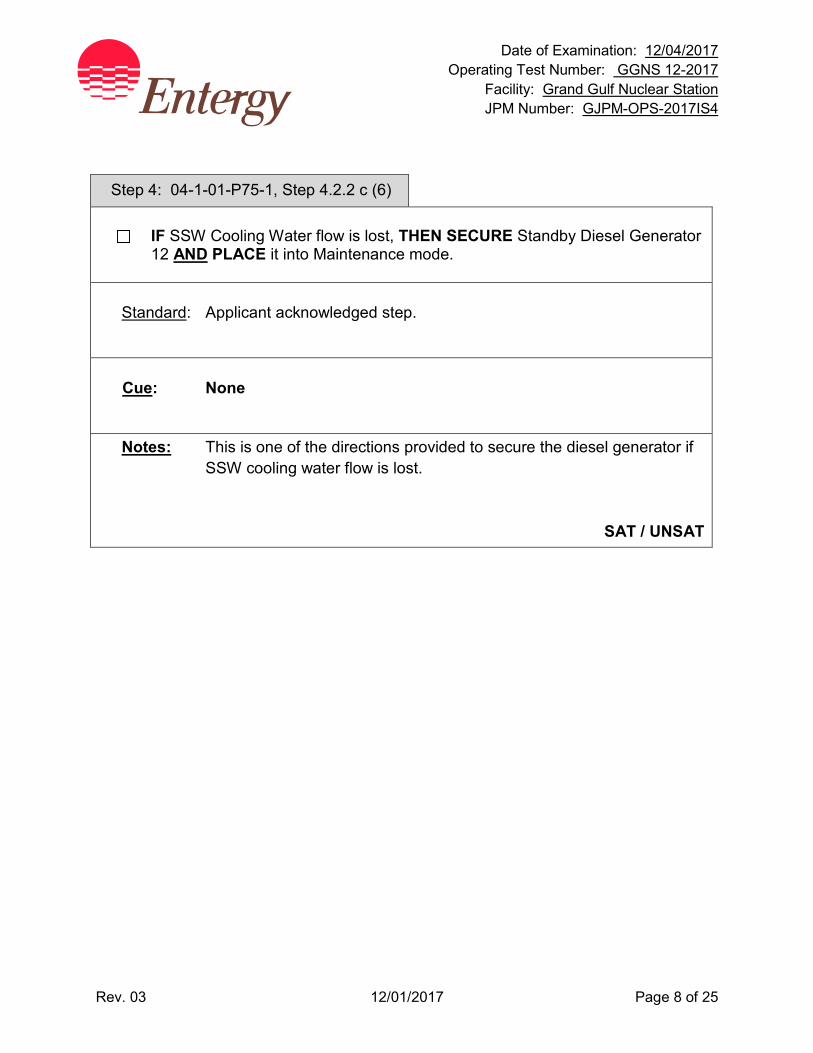
Date of Examination: 12/04/2017 Operating Test Number: GGNS 12-2017
Facility: Grand Gulf Nuclear Station JPM Number: GJPM-OPS-2017IS4
Rev. 03 12/01/2017 Page 8 of 25
Step 4: 04-1-01-P75-1, Step 4.2.2 c (6)
IF SSW Cooling Water flow is lost, THEN SECURE Standby Diesel Generator 12 AND PLACE it into Maintenance mode.
Standard: Applicant acknowledged step.
Cue: None
Notes: This is one of the directions provided to secure the diesel generator if SSW cooling water flow is lost.
SAT / UNSAT

Date of Examination: 12/04/2017 Operating Test Number: GGNS 12-2017
Facility: Grand Gulf Nuclear Station JPM Number: GJPM-OPS-2017IS4
Rev. 03 12/01/2017 Page 9 of 25
Step 5: 04-1-01-P75-1, Step 4.2.2 c (7)
DG Room O/A Fan 1X77-C001B Starts, 1H13-P864.
(a) Running in slow speed IF inlet temperature is ≤70°F. (b) Running in fast speed IF inlet temperature is >70°F. (c) Damper 1X77-F001B Opens.
(d) IF fan failed to start, THEN START per step 5.5. (e) IF fan CANNOT be started, THEN OPEN doors AND USE temporary fans as
needed to prolong diesel operation for critical loads
Standard: Observed DG room fan was running as indicated by either Lo or Hi speed red light ON and DG room damper open as indicated by red light ON, green light OFF. Determined steps (d) and (e) were N/A.
Cue: None
Notes: Light is on 1H13-P864 section 2C.
SAT / UNSAT
Step 6: 04-1-01-P75-1, Step 4.2.2 c (8)
DG 12 READY TO LOAD status light on 1H13-P864-2B illuminated for Division 2 DG.
Standard: Checked DG 12 READY TO LOAD status light was ON.
Cue: None
Notes: Light is on 1H13-P864 section 2B.
SAT / UNSAT
Date of Examination: 12/04/2017 Operating Test Number: GGNS 12-2017
Facility: Grand Gulf Nuclear Station JPM Number: GJPM-OPS-2017IS4
Rev. 03 12/01/2017 Page 10 of 25
NOTE
Oil addition with engine running should be made to bring level back to the black line on sight glass.
IF oil addition is required with engine loaded, oscillations in generator load May occur.
Examiner Note: Applicant should review NOTE prior to Step 4.2.2.c (9)
Step 7: 04-1-01-P75-1, Step 4.2.2 c (9)
CHECK that governor oil level is stable AND VISIBLE in sight glass.
Standard: Contacted local operator to verify governor oil level was stable and visible in sight-glass OR verified step was completed per Initial Conditions.
Cue: If asked, inform applicant that Governor oil level has been verified satisfactory per Initial Conditions.
Notes: None SAT / UNSAT
Step 8: 04-1-01-P75-1, Step 4.2.2 c (10)
IF DC Fuel Oil Booster pump has started, THEN STOP DC Fuel Oil Booster pump by TAKING its handswitch HS-M004B to OFF AND BACK to AUTO.
Standard: Contacted local operator to verify Fuel Oil Booster Pump status.
Cue: Fuel Oil Booster pump is not running.
Notes: None SAT / UNSAT
Date of Examination: 12/04/2017 Operating Test Number: GGNS 12-2017
Facility: Grand Gulf Nuclear Station JPM Number: GJPM-OPS-2017IS4
Rev. 03 12/01/2017 Page 11 of 25
NOTE
IF Aux Lube Oil pump is running, it May be shutdown at this time IF conditions of Precaution 3.29 are met.
REFER to Precaution 3.30. Examiner Note: Applicant should review NOTE prior to Step 4.2.2.c (11)
Step 9: 04-1-01-P75-1, Step 4.2.2 c (11)
IF Aux Lube Oil pump is running, THEN shutdown Aux Lube Oil pump by taking its handswitch HS-M031B to TRIP AND BACK to AUTO
Standard: Contacted local operator to verify Aux Lube Oil Pump status.
Cue: Aux Lube Oil pump is not running.
Notes: None SAT / UNSAT
Step 10: 04-1-01-P75-1, Step 4.2.2 c (12)
IF Aux Jacket Water Pump C004B is still running, VERIFY Jacket water pressure is >35 psi at R050B AND >15 psi at R020B with the engine at 450 rpm, THEN STOP AUX JACKET WATER PUMP C004B by PLACING its handswitch HS-M032B to TRIP AND THEN BACK to AUTO.
Standard: Contacted local operator to verify Aux Jacket Water Pump status.
Cue: Aux Jacket Water pump is not running.
Notes: None SAT / UNSAT
Date of Examination: 12/04/2017 Operating Test Number: GGNS 12-2017
Facility: Grand Gulf Nuclear Station JPM Number: GJPM-OPS-2017IS4
Rev. 03 12/01/2017 Page 12 of 25
Step 11: 04-1-01-P75-1, Step 4.2.2 d
SELECT phase of bus voltage to be MONITORED with VM 4.16 kV BUS 16AB VOLTMETER handswitch.
Standard: Observed voltmeter was selected to monitor bus 16AB voltage by handswitch selected to A-B, B-C, or C-A.
Cue: None
Notes: Handswitch is on 1H13-P864 section 2C Applicant does not have to change the selected phases monitored.
SAT / UNSAT
Step 12: 04-1-01-P75-1, Step 4.2.2 e
* PLACE Standby Diesel Generator 12 Output Breaker Synchronizing switch SYN CONT FDR BKR 152-1608 handswitch to ON.
Standard: Turned Sync Switch for Breaker 152-1608 to ON position.
Cue: None
Notes: Synchroscope on 1H13-P864 section 2B; Sync Switch on section 2C When Synchroscope is turned on, sync scope lights will be going ON and OFF.
SAT / UNSAT
Date of Examination: 12/04/2017 Operating Test Number: GGNS 12-2017
Facility: Grand Gulf Nuclear Station JPM Number: GJPM-OPS-2017IS4
Rev. 03 12/01/2017 Page 13 of 25
Step 13: 04-1-01-P75-1, Step 4.2.2 f & f(1)
* PLACE DG 12 PRL CONT handswitch momentarily to PRL (spring return to OFF) to defeat parallel interlock AND PLACES governor in the “DROOP” mode.
Standard: Momentarily placed DG 12 PRL CONT handswitch to PRL Indication - amber light above Div1 LSS PNL TEST MODE SEL
Switch ON
Cue: None
Notes: 1H13-P864 section 2C This places the Droop Circuit in service for the Diesel Generator.
SAT / UNSAT
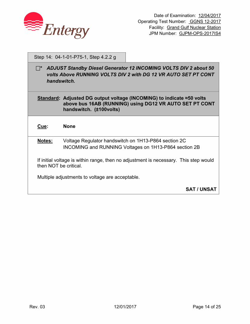
Date of Examination: 12/04/2017 Operating Test Number: GGNS 12-2017
Facility: Grand Gulf Nuclear Station JPM Number: GJPM-OPS-2017IS4
Rev. 03 12/01/2017 Page 14 of 25
Step 14: 04-1-01-P75-1, Step 4.2.2 g
* ADJUST Standby Diesel Generator 12 INCOMING VOLTS DIV 2 about 50 volts Above RUNNING VOLTS DIV 2 with DG 12 VR AUTO SET PT CONT handswitch.
Standard: Adjusted DG output voltage (INCOMING) to indicate ≈50 volts above bus 16AB (RUNNING) using DG12 VR AUTO SET PT CONT handswitch. (±100volts)
Cue: None
Notes: Voltage Regulator handswitch on 1H13-P864 section 2C INCOMING and RUNNING Voltages on 1H13-P864 section 2B If initial voltage is within range, then no adjustment is necessary. This step would then NOT be critical. Multiple adjustments to voltage are acceptable.
SAT / UNSAT
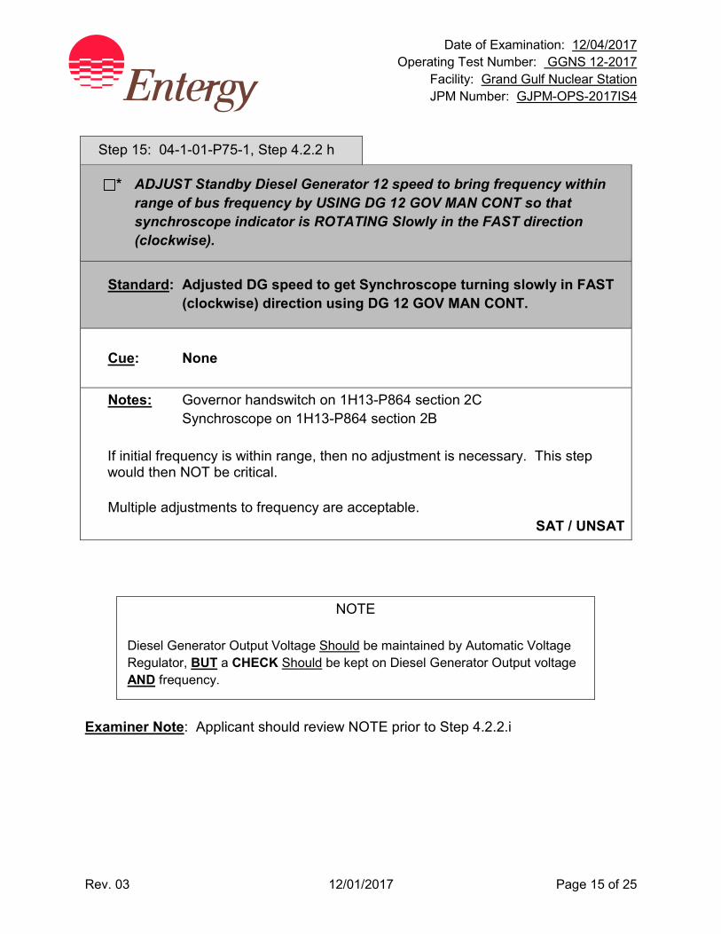
Date of Examination: 12/04/2017 Operating Test Number: GGNS 12-2017
Facility: Grand Gulf Nuclear Station JPM Number: GJPM-OPS-2017IS4
Rev. 03 12/01/2017 Page 15 of 25
Step 15: 04-1-01-P75-1, Step 4.2.2 h
* ADJUST Standby Diesel Generator 12 speed to bring frequency within range of bus frequency by USING DG 12 GOV MAN CONT so that synchroscope indicator is ROTATING Slowly in the FAST direction (clockwise).
Standard: Adjusted DG speed to get Synchroscope turning slowly in FAST (clockwise) direction using DG 12 GOV MAN CONT.
Cue: None
Notes: Governor handswitch on 1H13-P864 section 2C Synchroscope on 1H13-P864 section 2B If initial frequency is within range, then no adjustment is necessary. This step would then NOT be critical. Multiple adjustments to frequency are acceptable.
SAT / UNSAT
NOTE
Diesel Generator Output Voltage Should be maintained by Automatic Voltage Regulator, BUT a CHECK Should be kept on Diesel Generator Output voltage AND frequency.
Examiner Note: Applicant should review NOTE prior to Step 4.2.2.i
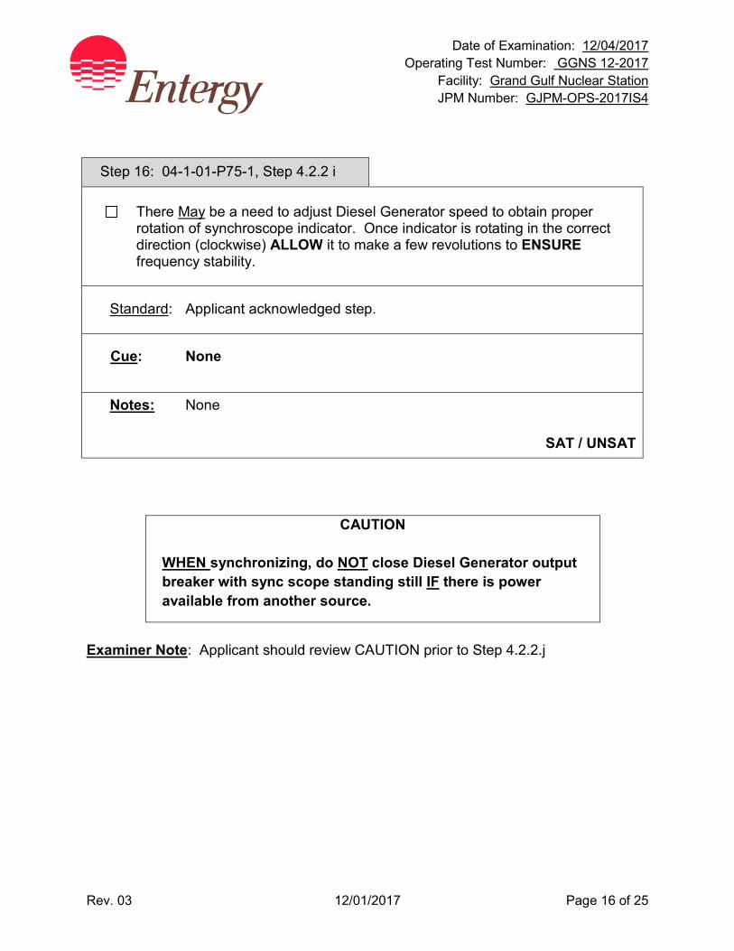
Date of Examination: 12/04/2017 Operating Test Number: GGNS 12-2017
Facility: Grand Gulf Nuclear Station JPM Number: GJPM-OPS-2017IS4
Rev. 03 12/01/2017 Page 16 of 25
Step 16: 04-1-01-P75-1, Step 4.2.2 i
There May be a need to adjust Diesel Generator speed to obtain proper rotation of synchroscope indicator. Once indicator is rotating in the correct direction (clockwise) ALLOW it to make a few revolutions to ENSURE frequency stability.
Standard: Applicant acknowledged step.
Cue: None
Notes: None
SAT / UNSAT
CAUTION
WHEN synchronizing, do NOT close Diesel Generator output breaker with sync scope standing still IF there is power available from another source.
Examiner Note: Applicant should review CAUTION prior to Step 4.2.2.j
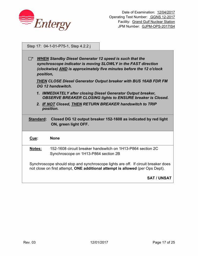
Date of Examination: 12/04/2017 Operating Test Number: GGNS 12-2017
Facility: Grand Gulf Nuclear Station JPM Number: GJPM-OPS-2017IS4
Rev. 03 12/01/2017 Page 17 of 25
Step 17: 04-1-01-P75-1, Step 4.2.2 j
* WHEN Standby Diesel Generator 12 speed is such that the synchroscope indicator is moving SLOWLY in the FAST direction (clockwise) AND is approximately five minutes before the 12 o'clock position,
THEN CLOSE Diesel Generator Output breaker with BUS 16AB FDR FM DG 12 handswitch.
1. IMMEDIATELY after closing Diesel Generator Output breaker, OBSERVE BREAKER CLOSING lights to ENSURE breaker is Closed.
2. IF NOT Closed, THEN RETURN BREAKER handswitch to TRIP position.
Standard: Closed DG 12 output breaker 152-1608 as indicated by red light ON, green light OFF.
Cue: None
Notes: 152-1608 circuit breaker handswitch on 1H13-P864 section 2C Synchroscope on 1H13-P864 section 2B Synchroscope should stop and synchroscope lights are off. If circuit breaker does not close on first attempt, ONE additional attempt is allowed (per Ops Dept).
SAT / UNSAT
Date of Examination: 12/04/2017 Operating Test Number: GGNS 12-2017
Facility: Grand Gulf Nuclear Station JPM Number: GJPM-OPS-2017IS4
Rev. 03 12/01/2017 Page 18 of 25
Step 18: 04-1-01-P75-1, Step 4.2.2 k
WHEN loading Diesel Generator to rated load, THEN MONITOR all exhaust temps. 1. IF any temp exceeds 960 deg F, THEN PERFORM the following:
a) Contact Engineering; b) Consider securing Diesel Generator
Standard: Applicant acknowledged step.
Cue: If asked, report all temperatures are < 960 °F.
Notes: None SAT / UNSAT
SIMULATOR OPERATOR MONITOR DG LOAD AND REACTIVE LOAD.
Step 19: 04-1-01-P75-1, Step 4.2.2 l
* Standby Diesel Generator 12 load May be raised by going to RAISE on GOV MAN CONT DG 12.
Standard: Real load on DG12 raised to ≈ 2-3 MWe using GOV MAN CONT as indicated on meter 1P75-R602B.
Cue: If asked, the local indicators for MWe and MVAR are reading same as Control Room indications.
Notes: DG12 load is indicated on 1P75-R602B, 1H13-P864 section 2B Applicant may make one or more adjustments to real load.
SAT / UNSAT
Date of Examination: 12/04/2017 Operating Test Number: GGNS 12-2017
Facility: Grand Gulf Nuclear Station JPM Number: GJPM-OPS-2017IS4
Rev. 03 12/01/2017 Page 19 of 25
Simulator Operator: When real load is raised to >2 MWe AND reactive load is raised > 1MVAR, SSW pump B will trip or Simulator Operator will TRIGGER EVENT 1.
Step 20: 04-1-01-P75-1, Step 4.2.2 m
* Diesel Generator 12 VARS loading May be adjusted with AUTO VOLT SET PT CONT DG12.
(1) For better electric governor control response, ADJUST VARS per Table below
Standard: Reactive load on DG12 raised to ≈1.5 MVAR using AUTO VOLT SET PT CONT as indicated on meter 1P75-R603B.
Cue: None
Notes: DG12 VARS is indicated on 1P75-R603B, 1H13-P864 section 2B.
Applicant may make one or more adjustments to reactive load as real load is increased.
SAT / UNSAT
Evaluator Note:
When DG12 real load is ~2.0MWe AND reactive load is ~1.0MVAR, Standby Service Water (SSW) Pump B will trip. This will begin the Alternate Path.
Date of Examination: 12/04/2017 Operating Test Number: GGNS 12-2017
Facility: Grand Gulf Nuclear Station JPM Number: GJPM-OPS-2017IS4
Rev. 03 12/01/2017 Page 20 of 25
Step 21: 04-1-01-P75-1, Step 4.2.2 n
PLACE SYNCHROSCOPE handswitch to OFF position as soon as Standby Diesel Generator 12 minimum load has stabilized.
Standard: SYNCHROSCOPE handswitch for breaker 152-1608 placed to OFF position.
Cue: None
Notes: Dependent upon when applicant recognizes the trip of SSW B, this step may not be performed.
SAT / UNSAT
Alternate path begins with the next step, designated by “AP”.
Date of Examination: 12/04/2017 Operating Test Number: GGNS 12-2017
Facility: Grand Gulf Nuclear Station JPM Number: GJPM-OPS-2017IS4
Rev. 03 12/01/2017 Page 21 of 25
AP Step 22: 04-1-01-P75-1, Step 4.2.2.c (6)
Recognizes SSW pump ‘B’ trip.
Standard: Recognized SSW pump ‘B’ tripped.
Cue: None
Notes: Indications on 1H13-P870 section 7A, 7B and 7C • SSW PMP B TRIP alarm (P870 7A-A1) • SSW B flow and pressure dropping to zero on 1P41-R606B • SSW PMP B handswitch green light ON and red light OFF
SAT / UNSAT
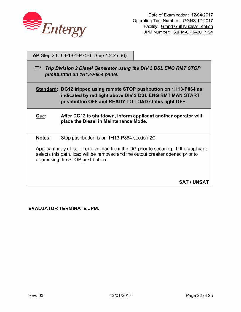
Date of Examination: 12/04/2017 Operating Test Number: GGNS 12-2017
Facility: Grand Gulf Nuclear Station JPM Number: GJPM-OPS-2017IS4
Rev. 03 12/01/2017 Page 22 of 25
AP Step 23: 04-1-01-P75-1, Step 4.2.2 c (6)
* Trip Division 2 Diesel Generator using the DIV 2 DSL ENG RMT STOP pushbutton on 1H13-P864 panel.
Standard: DG12 tripped using remote STOP pushbutton on 1H13-P864 as indicated by red light above DIV 2 DSL ENG RMT MAN START pushbutton OFF and READY TO LOAD status light OFF.
Cue: After DG12 is shutdown, inform applicant another operator will place the Diesel in Maintenance Mode.
Notes: Stop pushbutton is on 1H13-P864 section 2C Applicant may elect to remove load from the DG prior to securing. If the applicant selects this path, load will be removed and the output breaker opened prior to depressing the STOP pushbutton.
SAT / UNSAT
EVALUATOR TERMINATE JPM.
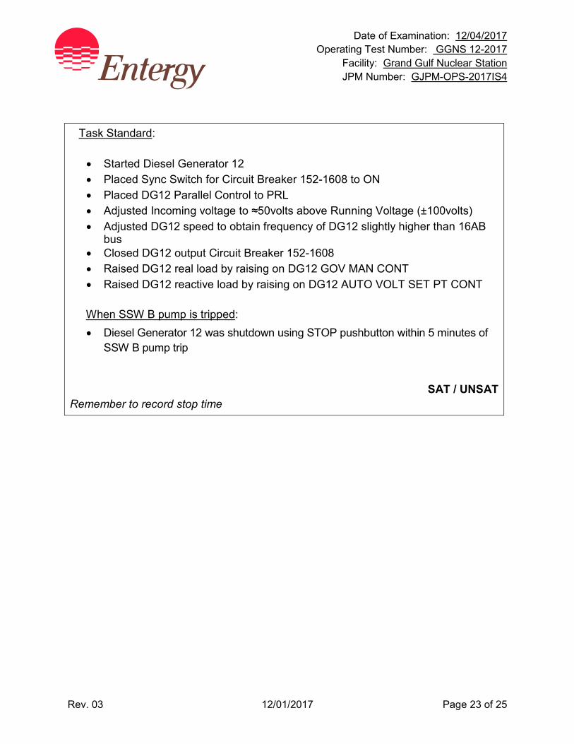
Date of Examination: 12/04/2017 Operating Test Number: GGNS 12-2017
Facility: Grand Gulf Nuclear Station JPM Number: GJPM-OPS-2017IS4
Rev. 03 12/01/2017 Page 23 of 25
Task Standard: • Started Diesel Generator 12 • Placed Sync Switch for Circuit Breaker 152-1608 to ON • Placed DG12 Parallel Control to PRL • Adjusted Incoming voltage to ≈50volts above Running Voltage (±100volts) • Adjusted DG12 speed to obtain frequency of DG12 slightly higher than 16AB
bus • Closed DG12 output Circuit Breaker 152-1608 • Raised DG12 real load by raising on DG12 GOV MAN CONT • Raised DG12 reactive load by raising on DG12 AUTO VOLT SET PT CONT When SSW B pump is tripped: • Diesel Generator 12 was shutdown using STOP pushbutton within 5 minutes of
SSW B pump trip
SAT / UNSAT
Remember to record stop time
Date of Examination: 12/04/2017 Operating Test Number: GGNS 12-2017
Facility: Grand Gulf Nuclear Station JPM Number: GJPM-OPS-2017IS4
Rev. 03 12/01/2017 Page 24 of 25
Follow-Up Questions & Answers:
Comments:
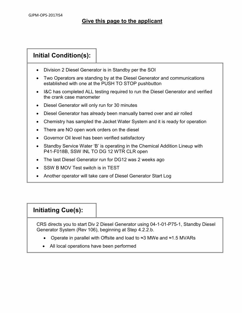
GJPM-OPS-2017IS4
Give this page to the applicant
Initial Condition(s):
• Division 2 Diesel Generator is in Standby per the SOI
• Two Operators are standing by at the Diesel Generator and communications established with one at the PUSH TO STOP pushbutton
• I&C has completed ALL testing required to run the Diesel Generator and verified the crank case manometer
• Diesel Generator will only run for 30 minutes
• Diesel Generator has already been manually barred over and air rolled
• Chemistry has sampled the Jacket Water System and it is ready for operation
• There are NO open work orders on the diesel
• Governor Oil level has been verified satisfactory
• Standby Service Water ‘B’ is operating in the Chemical Addition Lineup with P41-F018B, SSW INL TO DG 12 WTR CLR open
• The last Diesel Generator run for DG12 was 2 weeks ago
• SSW B MOV Test switch is in TEST
• Another operator will take care of Diesel Generator Start Log
Initiating Cue(s):
CRS directs you to start Div 2 Diesel Generator using 04-1-01-P75-1, Standby Diesel Generator System (Rev 106), beginning at Step 4.2.2.b.
• Operate in parallel with Offsite and load to ≈3 MWe and ≈1.5 MVARs
• All local operations have been performed

Date of Examination: 12/04/2017 Operating Test Number: GGNS 12-2017
Facility: Grand Gulf Nuclear Station JPM Number: GJPM-OPS-2017IS5
Rev. 01 11/09/2017 Page 1 of 14
2017I S5
GGNS
2017 NRC Operating Test
Job Performance Measure JPM Number: GJPM-OPS-2017IS5 JPM Title: Startup H2 Recombiner Facility Number: _GJPM-OPS-E6102_________ (If Bank or Modified from Bank)
JPM Attributes:
New Modified Direct from bank
Time Critical Alternate Path Validation Time: 15 min
Prepared By: Michael Rasch 11/09/2017 Exam Developer Date
Ops Review: Robert Brinkman 11/09/2017 1st Validation by Ops Rep or Ops Validation Crew Date
Validated By: Benny White \ Chase Miller 11/09/2017 2nd Validation by Ops Validation Crew Date
Approved By: Ricky Liddell 11/09/2017 Project Lead or Exam Team Lead Date

Date of Examination: 12/04/2017 Operating Test Number: LOT 2017I Facility: Grand Gulf Nuclear Station JPM Number: GJPM-OPS-2017IS5
Rev. 01 11/09/2017 Page 2 of 14
Startup H2 Recombiner
Time Critical Alternate Path Validation Time: 15 Min
Setting: Simulator Type: RO/SRO Task: GGNS-CRO-E61-EMERGENCY-4 K&A: 223001 A4.13 (3.4/3.4) 500000 EA1.03 (3.4/3.2) Generic 2.1.25 (3.9/4.2); 2.1.20 (4.6/4.6) Safety Function: 5 – Containment Integrity PRA Applicability: No 10CFR 55.45(a) (3); (4); (8) Performance: Perform Reference(s): 04-1-01-E61-1, Rev. 41, Combustible Gas Control
System Handout(s): 04-1-01-E61-1 # Manipulations: 5 # Critical Steps: 7 (1 calculation; 1 graph determination) Low Power: No Emergency/Abnormal: No RCA entry: No Engineered Safety Function: YES Simulator Setup/Required Plant Conditions:
• Reset Simulator to any IC
Safety Concerns:
• None.
Date of Examination: 12/04/2017 Operating Test Number: GGNS 12-2017
Facility: Grand Gulf Nuclear Station JPM Number: GJPM-OPS-2017IS5
Rev. 01 11/09/2017 Page 3 of 14
Name: _______________________ Time Start: _______ Time Stop: _______
Initial Condition(s):
• Combustible Gas Control System in standby
• Electrical is performing a test on Hydrogen Recombiner A
Initiating Cue(s): Control Room Supervisor directs you to start the A Hydrogen Recombiner per SOI 04-1-01-E61-1 section 5.4.2.a (1) - (10) Test directs you to assume the following conditions: Containment pressure is 2.0 psig Pre-LOCA Containment temperature is 80 degrees F
Date of Examination: 12/04/2017 Operating Test Number: GGNS 12-2017
Facility: Grand Gulf Nuclear Station JPM Number: GJPM-OPS-2017IS5
Rev. 01 11/09/2017 Page 4 of 14
Startup H2 Recombiner Notes to Evaluator:
• All control manipulations will be at panel 1H13-P870 in the Main Control Room. Task Overview: (Detailed description of task)
This task ensures the applicant can start a hydrogen recombiner for post-LOCA hydrogen removal. The ability to determine the correct power setting based upon containment parameters is also determined.

Date of Examination: 12/04/2017 Operating Test Number: GGNS 12-2017
Facility: Grand Gulf Nuclear Station JPM Number: GJPM-OPS-2017IS5
Rev. 01 11/09/2017 Page 5 of 14
Critical steps are shaded, bolded, italicized, and denoted by an (*) NOTE: Sequence of critical steps is critical unless otherwise noted. Step 1: 04-1-01-E61-1, Step 5.4.2.a (1)
ENSURE the H² RECOMB A PWR ADJ potentiometer is rotated fully counterclockwise to the zero power level.
Standard: Checked the ‘A’ H2 RECOMB PWR ADJ potentiometer is turned fully counter-clockwise with its numerical display counter “000”.
Cue: None
Notes: 1H13-P870 section 4C
SAT / UNSAT
Step 2: 04-1-01-E61-1, Step 5.4.2.a (2)
* START H2 RECOMB A by PLACING the appropriate handswitch on START.
Standard: Started H2 RECOMB A Indicated by red light on, green light off.
Cue: None
Notes: 1H13-P870 section 4C
SAT / UNSAT
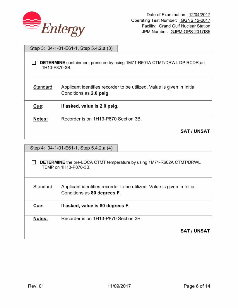
Date of Examination: 12/04/2017 Operating Test Number: GGNS 12-2017
Facility: Grand Gulf Nuclear Station JPM Number: GJPM-OPS-2017IS5
Rev. 01 11/09/2017 Page 6 of 14
Step 3: 04-1-01-E61-1, Step 5.4.2.a (3)
DETERMINE containment pressure by using 1M71-R601A CTMT/DRWL DP RCDR on 1H13-P870-3B.
Standard: Applicant identifies recorder to be utilized. Value is given in Initial
Conditions as 2.0 psig.
Cue: If asked, value is 2.0 psig.
Notes: Recorder is on 1H13-P870 Section 3B.
SAT / UNSAT
Step 4: 04-1-01-E61-1, Step 5.4.2.a (4)
DETERMINE the pre-LOCA CTMT temperature by using 1M71-R602A CTMT/DRWL TEMP on 1H13-P870-3B.
Standard: Applicant identifies recorder to be utilized. Value is given in Initial
Conditions as 80 degrees F.
Cue: If asked, value is 80 degrees F.
Notes: Recorder is on 1H13-P870 Section 3B.
SAT / UNSAT
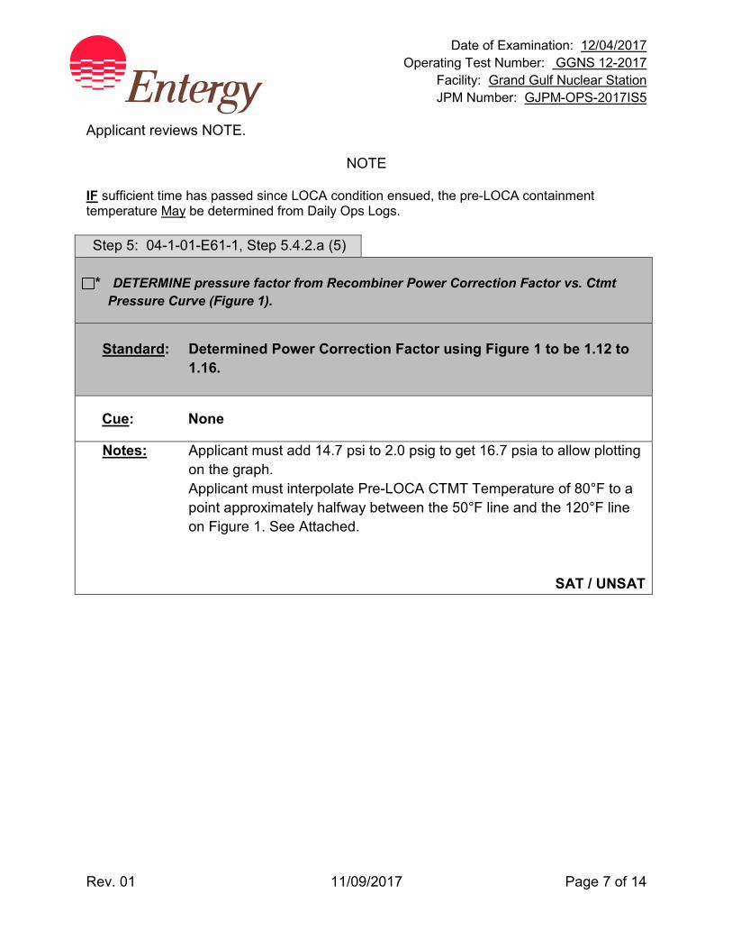
Date of Examination: 12/04/2017 Operating Test Number: GGNS 12-2017
Facility: Grand Gulf Nuclear Station JPM Number: GJPM-OPS-2017IS5
Rev. 01 11/09/2017 Page 7 of 14
Applicant reviews NOTE.
NOTE
IF sufficient time has passed since LOCA condition ensued, the pre-LOCA containment temperature May be determined from Daily Ops Logs. Step 5: 04-1-01-E61-1, Step 5.4.2.a (5) * DETERMINE pressure factor from Recombiner Power Correction Factor vs. Ctmt
Pressure Curve (Figure 1).
Standard: Determined Power Correction Factor using Figure 1 to be 1.12 to 1.16.
Cue: None
Notes: Applicant must add 14.7 psi to 2.0 psig to get 16.7 psia to allow plotting on the graph.
Applicant must interpolate Pre-LOCA CTMT Temperature of 80°F to a point approximately halfway between the 50°F line and the 120°F line on Figure 1. See Attached.
SAT / UNSAT
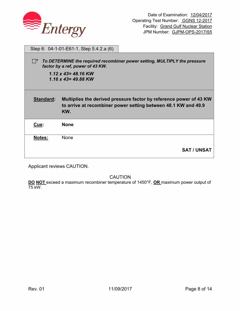
Date of Examination: 12/04/2017 Operating Test Number: GGNS 12-2017
Facility: Grand Gulf Nuclear Station JPM Number: GJPM-OPS-2017IS5
Rev. 01 11/09/2017 Page 8 of 14
Step 6: 04-1-01-E61-1, Step 5.4.2.a (6)
* To DETERMINE the required recombiner power setting, MULTIPLY the pressure factor by a ref, power of 43 KW.
1.12 x 43= 48.16 KW 1.16 x 43= 49.88 KW
Standard: Multiplies the derived pressure factor by reference power of 43 KW
to arrive at recombiner power setting between 48.1 KW and 49.9 KW.
Cue: None
Notes: None
SAT / UNSAT
Applicant reviews CAUTION.
CAUTION DO NOT exceed a maximum recombiner temperature of 1450°F, OR maximum power output of 75 kW.
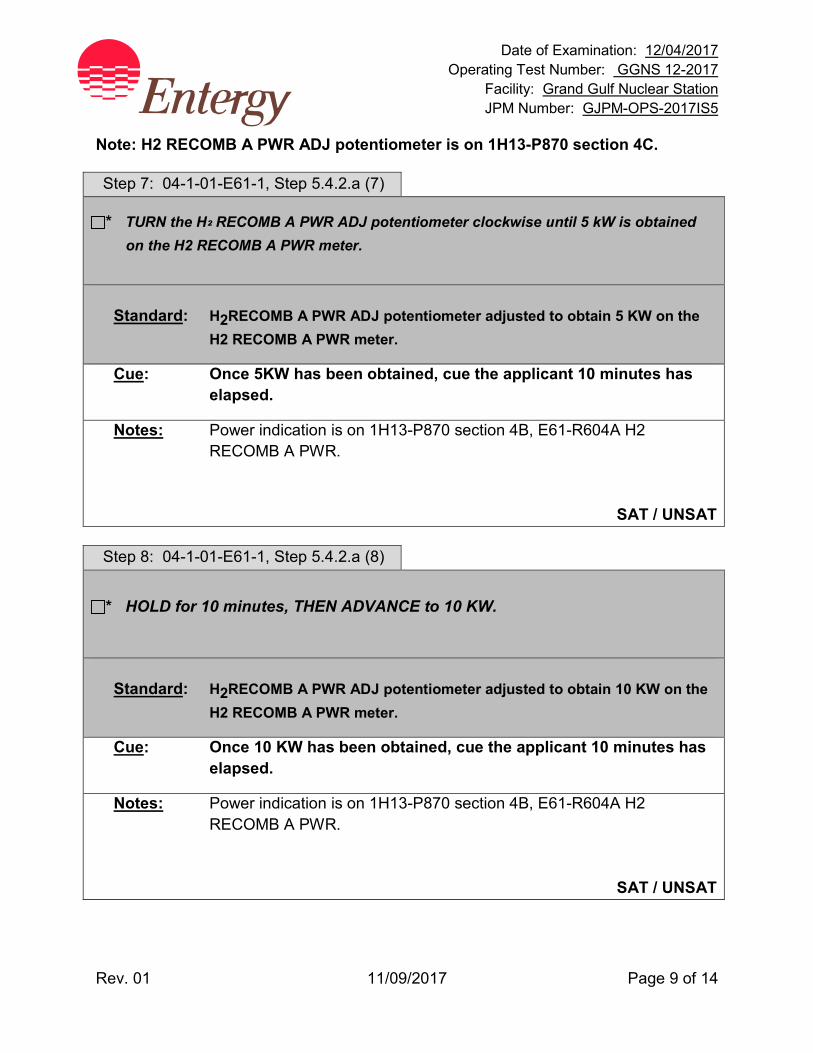
Date of Examination: 12/04/2017 Operating Test Number: GGNS 12-2017
Facility: Grand Gulf Nuclear Station JPM Number: GJPM-OPS-2017IS5
Rev. 01 11/09/2017 Page 9 of 14
Note: H2 RECOMB A PWR ADJ potentiometer is on 1H13-P870 section 4C. Step 7: 04-1-01-E61-1, Step 5.4.2.a (7)
* TURN the H² RECOMB A PWR ADJ potentiometer clockwise until 5 kW is obtained on the H2 RECOMB A PWR meter.
Standard: H2RECOMB A PWR ADJ potentiometer adjusted to obtain 5 KW on the
H2 RECOMB A PWR meter.
Cue: Once 5KW has been obtained, cue the applicant 10 minutes has elapsed.
Notes: Power indication is on 1H13-P870 section 4B, E61-R604A H2 RECOMB A PWR.
SAT / UNSAT Step 8: 04-1-01-E61-1, Step 5.4.2.a (8)
* HOLD for 10 minutes, THEN ADVANCE to 10 KW.
Standard: H2RECOMB A PWR ADJ potentiometer adjusted to obtain 10 KW on the
H2 RECOMB A PWR meter.
Cue: Once 10 KW has been obtained, cue the applicant 10 minutes has elapsed.
Notes: Power indication is on 1H13-P870 section 4B, E61-R604A H2 RECOMB A PWR.
SAT / UNSAT
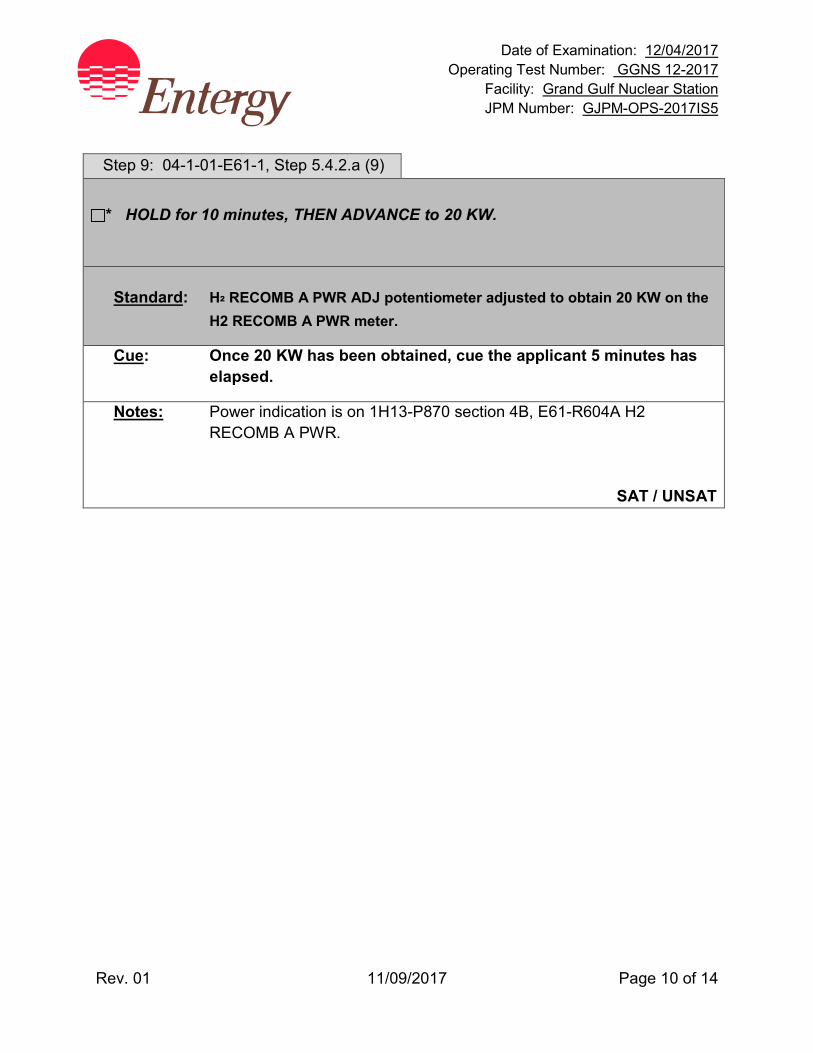
Date of Examination: 12/04/2017 Operating Test Number: GGNS 12-2017
Facility: Grand Gulf Nuclear Station JPM Number: GJPM-OPS-2017IS5
Rev. 01 11/09/2017 Page 10 of 14
Step 9: 04-1-01-E61-1, Step 5.4.2.a (9)
* HOLD for 10 minutes, THEN ADVANCE to 20 KW.
Standard: H² RECOMB A PWR ADJ potentiometer adjusted to obtain 20 KW on the
H2 RECOMB A PWR meter.
Cue: Once 20 KW has been obtained, cue the applicant 5 minutes has elapsed.
Notes: Power indication is on 1H13-P870 section 4B, E61-R604A H2 RECOMB A PWR.
SAT / UNSAT
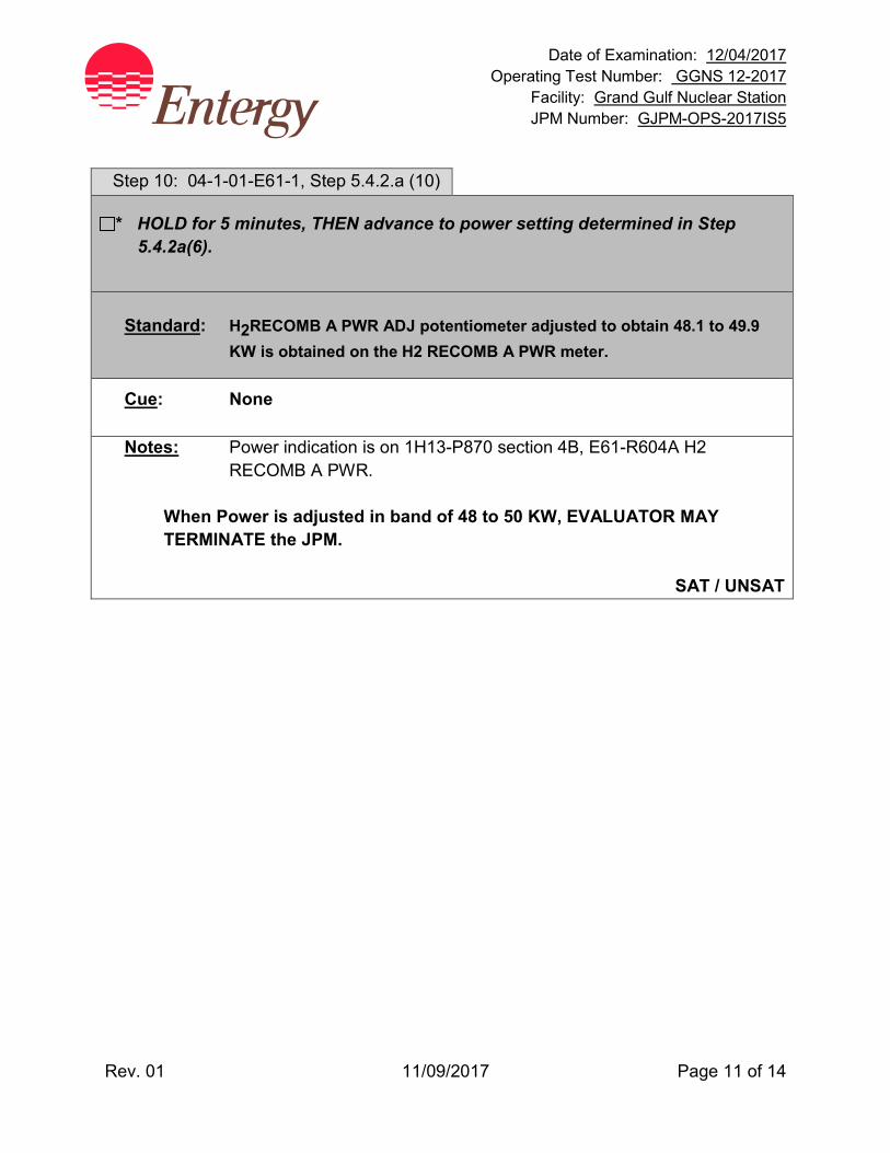
Date of Examination: 12/04/2017 Operating Test Number: GGNS 12-2017
Facility: Grand Gulf Nuclear Station JPM Number: GJPM-OPS-2017IS5
Rev. 01 11/09/2017 Page 11 of 14
Step 10: 04-1-01-E61-1, Step 5.4.2.a (10)
* HOLD for 5 minutes, THEN advance to power setting determined in Step 5.4.2a(6).
Standard: H2RECOMB A PWR ADJ potentiometer adjusted to obtain 48.1 to 49.9
KW is obtained on the H2 RECOMB A PWR meter.
Cue: None
Notes: Power indication is on 1H13-P870 section 4B, E61-R604A H2 RECOMB A PWR.
When Power is adjusted in band of 48 to 50 KW, EVALUATOR MAY TERMINATE the JPM.
SAT / UNSAT
Date of Examination: 12/04/2017 Operating Test Number: GGNS 12-2017
Facility: Grand Gulf Nuclear Station JPM Number: GJPM-OPS-2017IS5
Rev. 01 11/09/2017 Page 12 of 14
Task Standard(s):
• Started Hydrogen (H2) Recombiner A • Using Containment pressure and Pre-LOCA Containment Temperature,
determined Pressure Factor from Containment Recombiner Power Correction Factor versus Containment Pressure Figure 1 of 04-1-01-E61-1 (1.12 - 1.16)
• Determined final H2 Recombiner power setting (48.16KW - 49.88KW) • Raised H2 Recombiner power adjustment to:
5 KW 10 KW 20 KW
• H2 Recombiner A raised to final power setting between 48 KW and 50 KW
SAT / UNSAT Remember to record stop time
Date of Examination: 12/04/2017 Operating Test Number: GGNS 12-2017
Facility: Grand Gulf Nuclear Station JPM Number: GJPM-OPS-2017IS5
Rev. 01 11/09/2017 Page 13 of 14
Follow-Up Questions & Answers:
Comments:
GJPM-OPS-2017IS5
Give this page to the applicant
Initial Condition(s):
• Combustible Gas Control System in standby
• Electrical is performing a test on Hydrogen Recombiner A
Initiating Cue(s): Control Room Supervisor directs you to start the A Hydrogen Recombiner per SOI 04-1-01-E61-1 section 5.4.2.a (1) - (10) Test directs you to assume the following conditions: Containment pressure is 2.0 psig Pre-LOCA Containment temperature is 80 degrees F
Date of Examination: 12/04/2017 Operating Test Number: GGNS 12-2017
Facility: Grand Gulf Nuclear Station JPM Number: GJPM-OPS-2017IS6
Rev. 01 11/08/2017 Page 1 of 16
2017I S6
GGNS
2017 NRC Operating Test
Job Performance Measure JPM Number: GJPM-OPS-2017IS6 JPM Title: Secure Standby Gas Treatment Facility Number: __N/A__________ (If Bank or Modified from Bank)
JPM Attributes:
New Modified Direct from bank
Time Critical Alternate Path Validation Time: 15 min
Prepared By: Michael Rasch 11/08/2017 Exam Developer Date
Ops Review: Robert Brinkman 11/08/2017 1st Validation by Ops Rep or Ops Validation Crew Date
Validated By: Benny White \ Chase Miller 11/08/2017 2nd Validation by Ops Validation Crew Date
Approved By: Ricky Liddell 11/08/2017 Project Lead or Exam Team Lead Date
Date of Examination: 12/04/2017 Operating Test Number: GGNS 12-2017
Facility: Grand Gulf Nuclear Station JPM Number: GJPM-OPS-2017IS6
Rev. 01 11/08/2017 Page 2 of 16
Secure Standby Gas Treatment
Time Critical Alternate Path Validation Time: 15 Min
Setting: Simulator Type: RO/SRO Task: CRO-T48-OFFNORM-4 K&A: 261000 A4.03 (3.0/3.0); A4.02 (3.1/3.1) Generic 2.1.30 (4.4/4.0); 2.1.31 (4.6/4.3) Safety Function: 9 – Radioactivity Release PRA Applicability: No 10CFR55.45(a) (2); (3); (5); (8) Performance: Perform Reference(s): 04-1-01-T48-1, Rev. 36, Standby Gas Treatment Handout(s): 04-1-01-T48-1, Precautions & Limitations and Section 5.3 # Manipulations: 11 # Critical Steps: 9 Low Power: No Emergency/Abnormal: No RCA entry: No Engineered Safety Function: YES Simulator Setup/Required Plant Conditions:
• Reset Simulator to any IC • Place the handswitches for Fuel Handling Area and Fuel Pool Sweep Supply and Exhaust
Fans to STOP on 1H13-P842 • Manually initiate Standby Gas Treatment (SBGT) Trains A and B • Allow SBGT trains to stabilize
Safety Concerns:
• None
Date of Examination: 12/04/2017 Operating Test Number: GGNS 12-2017
Facility: Grand Gulf Nuclear Station JPM Number: GJPM-OPS-2017IS6
Rev. 01 11/08/2017 Page 3 of 16
Name: ___________________________ Time Start: _______ Time Stop: _______
Initial Condition(s):
• Both Standby Gas Trains are operating following a High-High Fuel Handling Area Radiation signal
• High-High Fuel Handling Area Radiation signal has been cleared and the cause of the High- High Radiation signal secured
• No jumpers have been installed on any control circuits
• Hand switches for Fuel Pool Sweep and Fuel Handling Area Supply and Exhaust fans have been placed to STOP on 1H13-P842
• Attachment VI was not installed and 1T42-B002 and 1T42-B005 Fan Coil Units were not restarted during this evolution
Initiating Cue(s):
• Control Room Supervisor directs you to place Standby Gas Treatment Train A in STANDBY per 04-1-01-T48-1 section 5.3
• Another operator will maintain the Accumulative Log Book • Another operator will secure Standby Gas Treatment Train B and restart Fuel Pool Sweep
and Fuel Handling Area Supply and Exhaust fans
Date of Examination: 12/04/2017 Operating Test Number: GGNS 12-2017
Facility: Grand Gulf Nuclear Station JPM Number: GJPM-OPS-2017IS6
Rev. 01 11/08/2017 Page 4 of 16
Place SBGT Train in Standby with an Auto Start Signal Present Notes to Evaluator:
• All controls will be from panel P870 in the Main Control Room.
Task Overview: (Detailed description of task)
Standby Gas Treatment System (SBGT) will automatically start on a LOCA signal or High-High Radiation signals in Fuel Handling Exhaust or Fuel Pool Sweep Exhaust ventilation. When initiating conditions are restored, SBGT is restored to a standby configuration. Restoring SBGT to standby will reduce differential pressure in the Auxiliary Building thus reducing hazards to personnel entering and exiting the building. This JPM will evaluate the applicant's ability to place Standby Gas Treatment (SBGT) System in Standby following an Automatic Initiation signal.
Date of Examination: 12/04/2017 Operating Test Number: GGNS 12-2017
Facility: Grand Gulf Nuclear Station JPM Number: GJPM-OPS-2017IS6
Rev. 01 11/08/2017 Page 5 of 16
Critical steps are underlined, italicized, and denoted by an (*) NOTE: The sequence of the following steps is critical unless otherwise noted. Step 1: 04-1-01-T48-1, Step 5.3.2a(1 - 3)
IF Attachment VI was installed to restart 1T42B002 AND 1T42B005 fan coil units, THEN PERFORM the following to restore control circuits to normal:
(1) PLACE handswitch for 1T42B005 (HS-M001) to STOP. (Area 10/185)
(2) PLACE handswitch for 1T42B002 (HS-M002) to STOP. (1H22P178)
(3) PERFORM Attachment VI restoration.
Standard: Step may be N/A’d based on Initial Conditions.
Cue: None
Notes: None
SAT / UNSAT
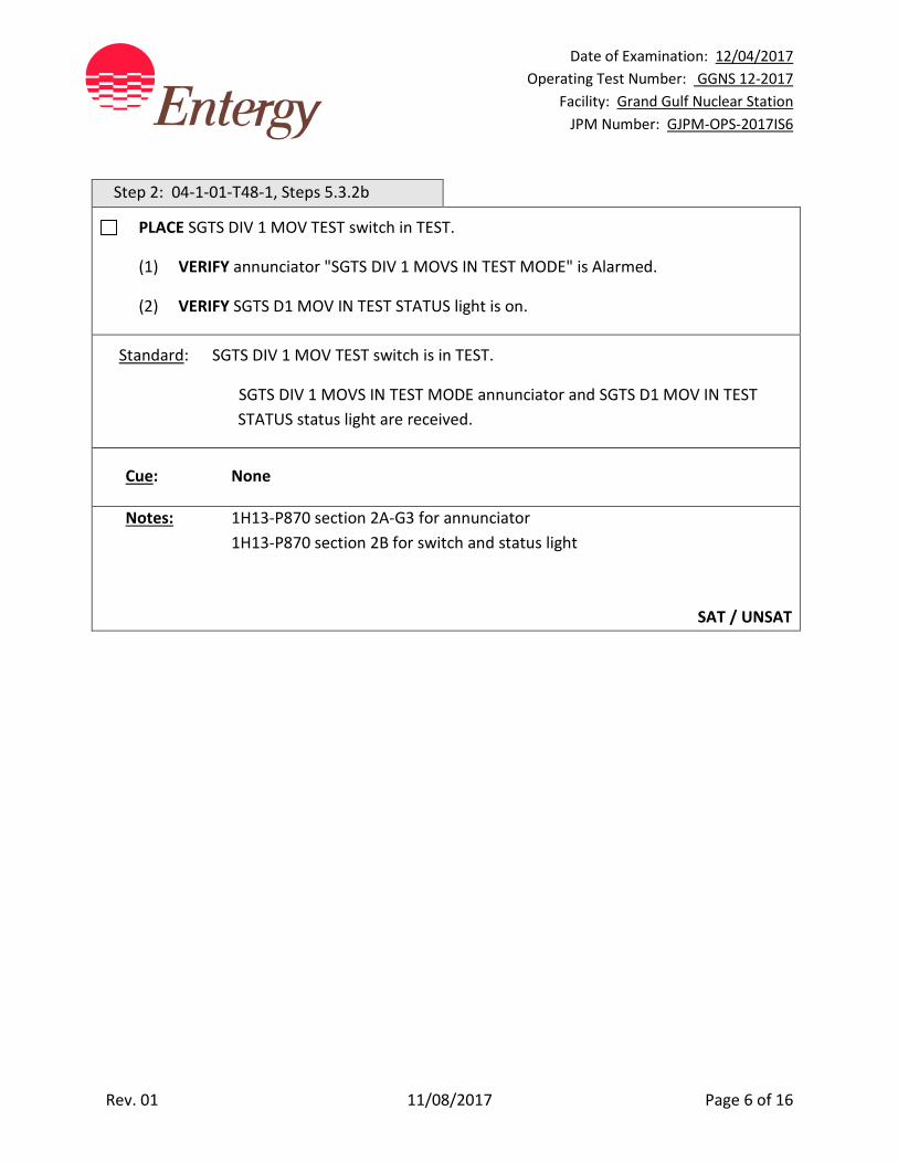
Date of Examination: 12/04/2017 Operating Test Number: GGNS 12-2017
Facility: Grand Gulf Nuclear Station JPM Number: GJPM-OPS-2017IS6
Rev. 01 11/08/2017 Page 6 of 16
Step 2: 04-1-01-T48-1, Steps 5.3.2b
PLACE SGTS DIV 1 MOV TEST switch in TEST.
(1) VERIFY annunciator "SGTS DIV 1 MOVS IN TEST MODE" is Alarmed.
(2) VERIFY SGTS D1 MOV IN TEST STATUS light is on.
Standard: SGTS DIV 1 MOV TEST switch is in TEST.
SGTS DIV 1 MOVS IN TEST MODE annunciator and SGTS D1 MOV IN TEST STATUS status light are received.
Cue: None
Notes: 1H13-P870 section 2A-G3 for annunciator 1H13-P870 section 2B for switch and status light
SAT / UNSAT

Date of Examination: 12/04/2017 Operating Test Number: GGNS 12-2017
Facility: Grand Gulf Nuclear Station JPM Number: GJPM-OPS-2017IS6
Rev. 01 11/08/2017 Page 7 of 16
Step 3: 04-1-01-T48-1, Step 5.3.2c
PLACE the following handswitches to STOP on 1H13P842:
1T42C002A FHA EXH FAN A
1T42C004A POOL SWP EXH FAN A
1T42C002B FHA EXH FAN B
1T42C004B POOL SWP EXH FAN B
1T42C001A FHA SPLY FAN A
1T42C003A FP SWP SPLY FAN A
1T42C001B FHA SPLY FAN B
1T42C003B FP SWP SPLY FAN B
Standard: Step may be marked as complete based on Initial Conditions.
Cue: None
Notes: None
SAT / UNSAT
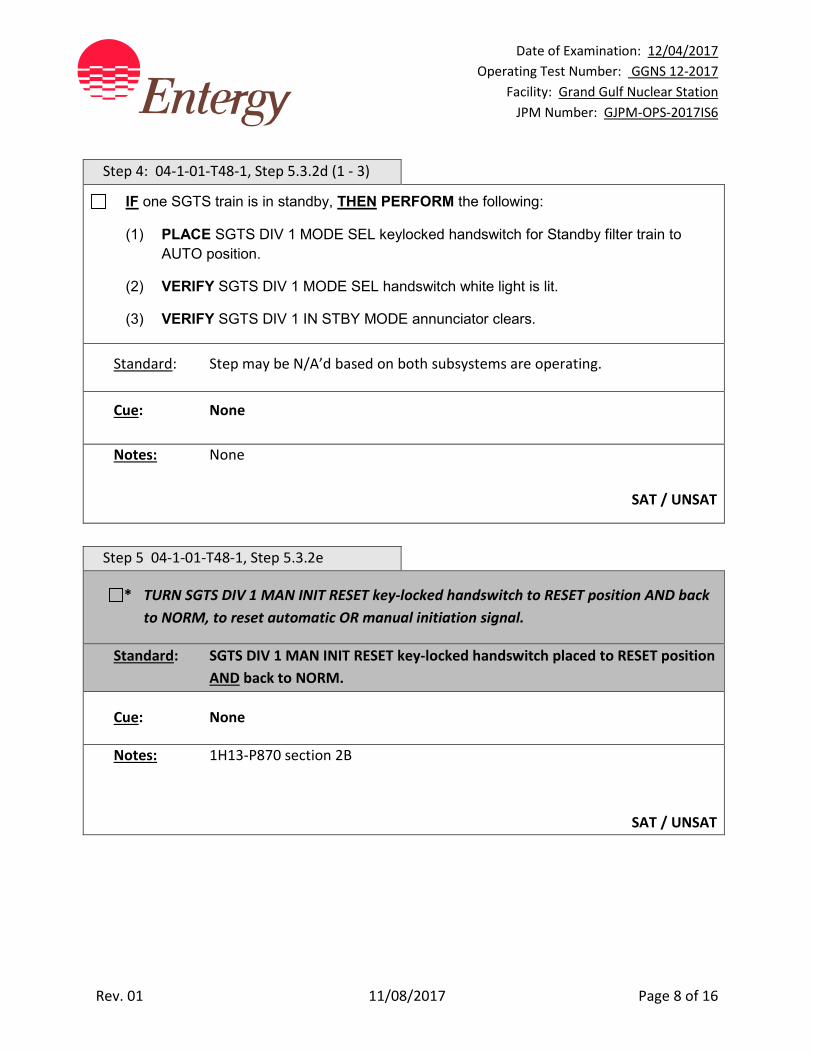
Date of Examination: 12/04/2017 Operating Test Number: GGNS 12-2017
Facility: Grand Gulf Nuclear Station JPM Number: GJPM-OPS-2017IS6
Rev. 01 11/08/2017 Page 8 of 16
Step 4: 04-1-01-T48-1, Step 5.3.2d (1 - 3)
IF one SGTS train is in standby, THEN PERFORM the following:
(1) PLACE SGTS DIV 1 MODE SEL keylocked handswitch for Standby filter train to AUTO position.
(2) VERIFY SGTS DIV 1 MODE SEL handswitch white light is lit.
(3) VERIFY SGTS DIV 1 IN STBY MODE annunciator clears.
Standard: Step may be N/A’d based on both subsystems are operating.
Cue: None
Notes: None
SAT / UNSAT
Step 5 04-1-01-T48-1, Step 5.3.2e
* TURN SGTS DIV 1 MAN INIT RESET key-locked handswitch to RESET position AND back to NORM, to reset automatic OR manual initiation signal.
Standard: SGTS DIV 1 MAN INIT RESET key-locked handswitch placed to RESET position AND back to NORM.
Cue: None
Notes: 1H13-P870 section 2B
SAT / UNSAT
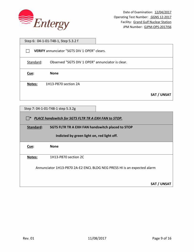
Date of Examination: 12/04/2017 Operating Test Number: GGNS 12-2017
Facility: Grand Gulf Nuclear Station JPM Number: GJPM-OPS-2017IS6
Rev. 01 11/08/2017 Page 9 of 16
Step 6: 04-1-01-T48-1, Step 5.3.2 f
VERIFY annunciator "SGTS DIV 1 OPER" clears.
Standard: Observed "SGTS DIV 1 OPER" annunciator is clear.
Cue: None
Notes: 1H13-P870 section 2A
SAT / UNSAT
Step 7: 04-1-01-T48-1 step 5.3.2g
* PLACE handswitch for SGTS FLTR TR A EXH FAN to STOP.
Standard: SGTS FLTR TR A EXH FAN handswitch placed to STOP
Indicted by green light on, red light off.
Cue: None
Notes: 1H13-P870 section 2C Annunciator 1H13-P870 2A-E2 ENCL BLDG NEG PRESS HI is an expected alarm
SAT / UNSAT
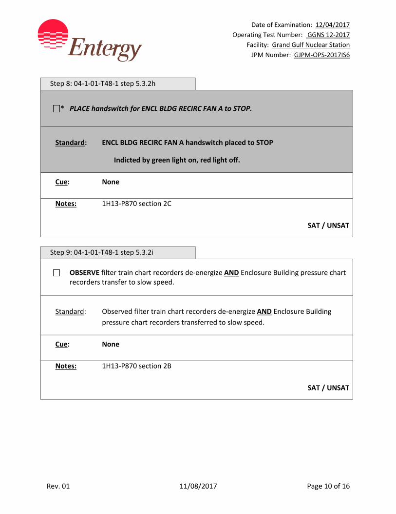
Date of Examination: 12/04/2017 Operating Test Number: GGNS 12-2017
Facility: Grand Gulf Nuclear Station JPM Number: GJPM-OPS-2017IS6
Rev. 01 11/08/2017 Page 10 of 16
Step 8: 04-1-01-T48-1 step 5.3.2h
* PLACE handswitch for ENCL BLDG RECIRC FAN A to STOP.
Standard: ENCL BLDG RECIRC FAN A handswitch placed to STOP
Indicted by green light on, red light off.
Cue: None
Notes: 1H13-P870 section 2C
SAT / UNSAT
Step 9: 04-1-01-T48-1 step 5.3.2i
OBSERVE filter train chart recorders de-energize AND Enclosure Building pressure chart recorders transfer to slow speed.
Standard: Observed filter train chart recorders de-energize AND Enclosure Building
pressure chart recorders transferred to slow speed.
Cue: None
Notes: 1H13-P870 section 2B
SAT / UNSAT
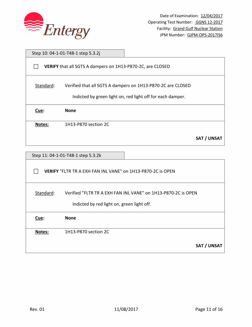
Date of Examination: 12/04/2017 Operating Test Number: GGNS 12-2017
Facility: Grand Gulf Nuclear Station JPM Number: GJPM-OPS-2017IS6
Rev. 01 11/08/2017 Page 11 of 16
Step 10: 04-1-01-T48-1 step 5.3.2j
VERIFY that all SGTS A dampers on 1H13-P870-2C, are CLOSED
Standard: Verified that all SGTS A dampers on 1H13-P870-2C are CLOSED
Indicted by green light on, red light off for each damper.
Cue: None
Notes: 1H13-P870 section 2C
SAT / UNSAT
Step 11: 04-1-01-T48-1 step 5.3.2k
VERIFY "FLTR TR A EXH FAN INL VANE" on 1H13-P870-2C is OPEN
Standard: Verified "FLTR TR A EXH FAN INL VANE" on 1H13-P870-2C is OPEN
Indicted by red light on, green light off.
Cue: None
Notes: 1H13-P870 section 2C
SAT / UNSAT
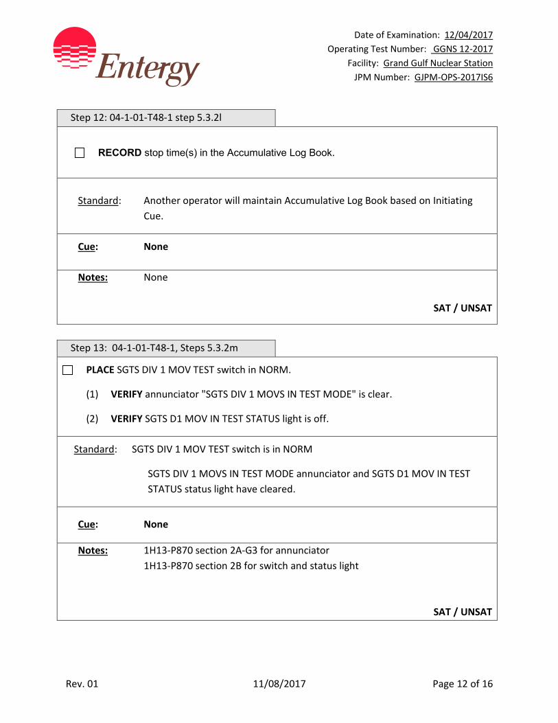
Date of Examination: 12/04/2017 Operating Test Number: GGNS 12-2017
Facility: Grand Gulf Nuclear Station JPM Number: GJPM-OPS-2017IS6
Rev. 01 11/08/2017 Page 12 of 16
Step 12: 04-1-01-T48-1 step 5.3.2l
RECORD stop time(s) in the Accumulative Log Book.
Standard: Another operator will maintain Accumulative Log Book based on Initiating
Cue.
Cue: None
Notes: None
SAT / UNSAT
Step 13: 04-1-01-T48-1, Steps 5.3.2m
PLACE SGTS DIV 1 MOV TEST switch in NORM.
(1) VERIFY annunciator "SGTS DIV 1 MOVS IN TEST MODE" is clear.
(2) VERIFY SGTS D1 MOV IN TEST STATUS light is off.
Standard: SGTS DIV 1 MOV TEST switch is in NORM
SGTS DIV 1 MOVS IN TEST MODE annunciator and SGTS D1 MOV IN TEST STATUS status light have cleared.
Cue: None
Notes: 1H13-P870 section 2A-G3 for annunciator 1H13-P870 section 2B for switch and status light
SAT / UNSAT

Date of Examination: 12/04/2017 Operating Test Number: GGNS 12-2017
Facility: Grand Gulf Nuclear Station JPM Number: GJPM-OPS-2017IS6
Rev. 01 11/08/2017 Page 13 of 16
Step 14: 04-1-01-T48-1 step 5.3.2n
* IF SBGT A was secured, THEN OPEN the following dampers:
1T42F011
1T42F019
1T42F004
1M41F008
1M41F036
1T41F007
Standard: Opened above listed dampers
Indicated by red light on, green light off.
Cue: None
Notes: 1H13-P870 section 2C
SAT / UNSAT
EVALUATOR NOTE: SBGT A Train has been shutdown inform applicant the JPM is TERMINATED.
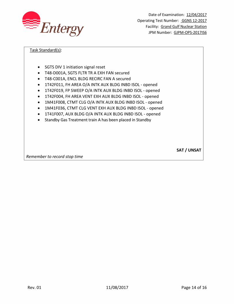
Date of Examination: 12/04/2017 Operating Test Number: GGNS 12-2017
Facility: Grand Gulf Nuclear Station JPM Number: GJPM-OPS-2017IS6
Rev. 01 11/08/2017 Page 14 of 16
Task Standard(s):
• SGTS DIV 1 initiation signal reset • T48-D001A, SGTS FLTR TR A EXH FAN secured • T48-C001A, ENCL BLDG RECIRC FAN A secured • 1T42F011, FH AREA O/A INTK AUX BLDG INBD ISOL - opened • 1T42F019, FP SWEEP O/A INTK AUX BLDG INBD ISOL - opened • 1T42F004, FH AREA VENT EXH AUX BLDG INBD ISOL - opened • 1M41F008, CTMT CLG O/A INTK AUX BLDG INBD ISOL - opened • 1M41F036, CTMT CLG VENT EXH AUX BLDG INBD ISOL - opened • 1T41F007, AUX BLDG O/A INTK AUX BLDG INBD ISOL - opened • Standby Gas Treatment train A has been placed in Standby
SAT / UNSAT
Remember to record stop time

Date of Examination: 12/04/2017 Operating Test Number: GGNS 12-2017
Facility: Grand Gulf Nuclear Station JPM Number: GJPM-OPS-2017IS6
Rev. 01 11/08/2017 Page 15 of 16
Follow-Up Questions & Answers:
Comments:
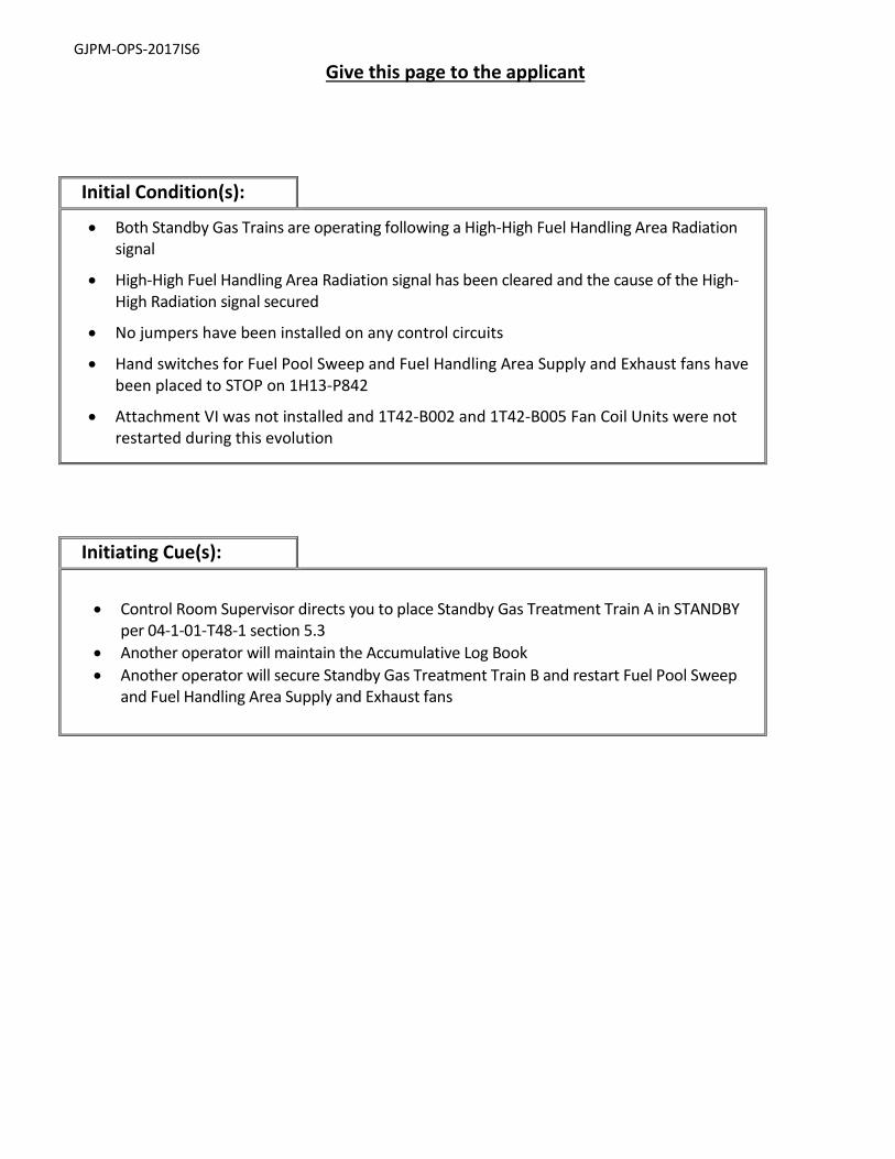
GJPM-OPS-2017IS6
Give this page to the applicant
Initial Condition(s):
• Both Standby Gas Trains are operating following a High-High Fuel Handling Area Radiation signal
• High-High Fuel Handling Area Radiation signal has been cleared and the cause of the High- High Radiation signal secured
• No jumpers have been installed on any control circuits
• Hand switches for Fuel Pool Sweep and Fuel Handling Area Supply and Exhaust fans have been placed to STOP on 1H13-P842
• Attachment VI was not installed and 1T42-B002 and 1T42-B005 Fan Coil Units were not restarted during this evolution
Initiating Cue(s):
• Control Room Supervisor directs you to place Standby Gas Treatment Train A in STANDBY per 04-1-01-T48-1 section 5.3
• Another operator will maintain the Accumulative Log Book • Another operator will secure Standby Gas Treatment Train B and restart Fuel Pool Sweep
and Fuel Handling Area Supply and Exhaust fans
Date of Examination: 12/04/2017 Operating Test Number: GGNS 12-2017
Facility: Grand Gulf Nuclear Station JPM Number: GJPM-OPS-2017IS7
Rev. 01 11/09/2017 Page 1 of 23
2017I S7
GGNS
2017 NRC Operating Test
Job Performance Measure JPM Number: GJPM-OPS-2017IS7 JPM Title: Shift Reactor Recirc Pump B to Fast
Speed Facility Number: _GJPM-OPS-B3306_________ (If Bank or Modified from Bank)
JPM Attributes:
New Modified Direct from bank
Time Critical Alternate Path Validation Time: 25 min
Prepared By: Michael Rasch 11/09/2017 Exam Developer Date
Ops Review: Robert Brinkman 11/09/2017 1st Validation by Ops Rep or Ops Validation Crew Date
Validated By: Benny White \ Chase Miller 11/09/2017 2nd Validation by Ops Validation Crew Date
Approved By: Ricky Liddell 11/09/2017 Project Lead or Exam Team Lead Date

Date of Examination: 12/04/2017 Operating Test Number: LOT 2017I Facility: Grand Gulf Nuclear Station JPM Number: GJPM-OPS-2017IS7
Rev. 01 11/09/2017 Page 2 of 23
Shift Reactor Recirc Pump B to Fast Speed
Time Critical Alternate Path Validation Time: 25 Min Setting: Simulator Type: RO/SRO Task: GGNS-CRO-B33(1)-NORMAL-1.3 K&A: 202001 A4.01 (3.7/3.7) Safety Function: 1 – Reactivity Control 4 – Heat Removal from Reactor Core PRA Applicability: No 10CFR 55.45(a) (3); (4); (7) Performance: Perform 04-1-01-B33-1, Rev. 163, Reactor Recirculation System 04-1-02-1H13-P680-3A-D9 Rev. 181, Alarm Response
Instructions 1H13-P680 04-1-01-R21-12, Rev. 40, BOP Bus 12HE 05-1-02-III-3 Rev. 115, Reduction in Recirculation
System Flow Rate Handout(s): 04-1-01-B33-1 04-1-01-R21-12 # Manipulations: 7 # Critical Steps: 4 Low Power: No Emergency/Abnormal: No RCA entry: No Engineered Safety Function: No Simulator Setup/Required Plant Conditions:
• Reset Simulator to 27% power IC • Verify plant power between 30% and 32% power • Verify load line < 75% • Verify feedwater flow > 4.0 mlbm/hr • Verify Reactor Recirc Pump ‘B’ operating in SLOW speed with FCV 97% open • Verify Reactor Recirc Pump ‘A’ operating in FAST speed with FCV at min
position • Pull Sheet completed through step 143 • Verify that all prerequisites contained in section 4.2.1 of 04-1-01-B33-1 are
satisfied. (Provide applicant with marked up copy of SOI) • Verify Malfunction rr196b (Incomplete Sequence B) in Summary
Safety Concerns: None
Date of Examination: 12/04/2017 Operating Test Number: LOT 2017I Facility: Grand Gulf Nuclear Station JPM Number: GJPM-OPS-2017IS7
Rev. 01 11/09/2017 Page 3 of 23
Name: _______________________ Time Start: _______ Time Stop: _______
Initial Condition(s): • Plant is in power ascension, at approximately 32% rated thermal power • Reactor Recirc Pump A is in FAST speed • Breakers CB-3B and CB-4B are racked in and closed • Requirements for entry into Controlled Entry Region of Power to Flow Map have
been met • Reactor Recirc Pump B pump and motor temperatures are normal on recorder
1B33-TR-R601 • Chemistry and Radiation Protection personnel have been notified of the Reactor
Recirc Pump up shift and crud burst
Initiating Cue(s):
Control Room Supervisor directs you to shift Reactor Recirc Pump B to FAST speed in accordance with 04-1-01-B33-1 Section 4.2.2.
Date of Examination: 12/04/2017 Operating Test Number: LOT 2017I Facility: Grand Gulf Nuclear Station JPM Number: GJPM-OPS-2017IS7
Rev. 01 11/09/2017 Page 4 of 23
Shift Reactor Recirc Pump B to Fast Speed Notes to Evaluator:
All controls and indication for this task are on panel 1H13-P680. Several parameter verifications must be made prior to transferring a Recirc pump to fast speed. The standard for doing so offers only one source for this instrumentation. There may be more than one source, so the standard usually states "or equivalent" to let the evaluator know that there may another legitimate way to verify the parameter. Unless otherwise indicated, all controls and indications for this task are on panel 1H13-P680-3A - 3D. If asked about monitoring for THI, inform the applicant that another operator will monitor for THI. This task begins at 04-1-01-B33-1 Step 4.2.2.
Task Overview: (Detailed description of task)
This task shifts the second Reactor Recirculation Pump to fast speed in preparation for power ascension. First recirc pump is already in fast speed. Fault in this task is that RRP fast speed breaker CB-5B fails to close, resulting in an Incomplete Start Sequence and a system shutdown. Applicant will enter the Reduction in Recirculation System Flow ONEP and close the discharge valve for the B Recirc Pump completing the JPM. Core must be closely monitored for Thermal Hydraulic Instability (THI). For this task, it will be assumed that another operator will monitor for THI.
Date of Examination: 12/04/2017 Operating Test Number: LOT 2017I Facility: Grand Gulf Nuclear Station JPM Number: GJPM-OPS-2017IS7
Rev. 01 11/09/2017 Page 5 of 23
Critical steps are shaded, bolded, italicized, and denoted by an (*). Applicant will review NOTE and CAUTIONS. 04-1-01-B33-1 step 4.2.2 NOTE and CAUTIONS
NOTE
PRIOR to upshift, the respective Recirc Loop FCV should be at the MIN ED Position Interlock as indicated on PDS computer. This will assist in opening of FCV AFTER shifting to fast speed AND minimize pressure surges on Recirc seal. IF using computer point to help DETERMINE MIN ED valve position, FCV should be approximately 20 percent. At this FCV position, it is normal for Jet Pump flows AND Loop flow in affected Loop to indicate near zero due to flow resistance.
Closing FCV to MIN ED position WHEN on LFMG may be done in FAST DETENT UNTIL FCV is approximately 20 PERCENT OPEN.
Attachment X, OPERATION OF RECIRCULATION SYSTEM FLOW CONTROL VALVES hard card is available for referencing/use WHEN adjusting Recirculation Loop flow rates/Total Core flow rate.
CAUTION
The closure of the Recirculation FCV places the Reactor closer to a region of potential instability. Greater monitoring of the APRMs, LPRMs, SRM Period Meters, AND OPRM Computer trends is warranted. ALSO MINIMIZE throttling the FCVs DURING Recirc fast speed AND LFMG operation to discourage pump shaft cracking propagation.
CAUTION
WHEN closing Recirculation FCV, Feedwater flow must be maintained above 3.0 Mlbm/hr to prevent an automatic transfer to slow speed. WITH one Recirculation Pump in fast speed, Jet Pump flow may stall in the slow-speed Loop as the Flow Control Valve is closed to MIN ED position. IF Jet Pump stall flow occurs, as indicated by no flow in the loop jet pumps, THEN the slow speed loop should be shifted to fast speed OR the fast speed loop shifted to slow speed WITHIN one hour.
04-1-01-B33-1 step 4.2.2.1
Shift Reactor Recirc Pump B to fast speed as follows:
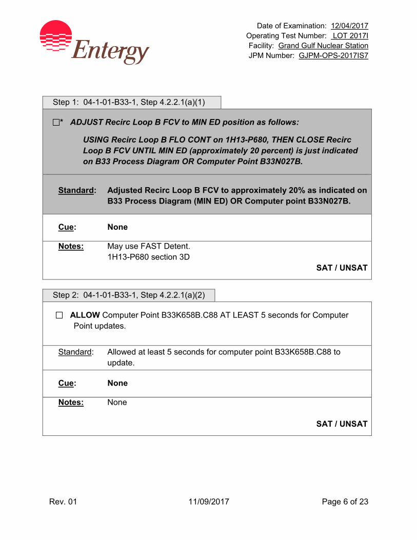
Date of Examination: 12/04/2017 Operating Test Number: LOT 2017I Facility: Grand Gulf Nuclear Station JPM Number: GJPM-OPS-2017IS7
Rev. 01 11/09/2017 Page 6 of 23
Step 1: 04-1-01-B33-1, Step 4.2.2.1(a)(1)
* ADJUST Recirc Loop B FCV to MIN ED position as follows:
USING Recirc Loop B FLO CONT on 1H13-P680, THEN CLOSE Recirc Loop B FCV UNTIL MIN ED (approximately 20 percent) is just indicated on B33 Process Diagram OR Computer Point B33N027B.
Standard: Adjusted Recirc Loop B FCV to approximately 20% as indicated on
B33 Process Diagram (MIN ED) OR Computer point B33N027B.
Cue: None
Notes: May use FAST Detent. 1H13-P680 section 3D
SAT / UNSAT
Step 2: 04-1-01-B33-1, Step 4.2.2.1(a)(2)
ALLOW Computer Point B33K658B.C88 AT LEAST 5 seconds for Computer Point updates.
Standard: Allowed at least 5 seconds for computer point B33K658B.C88 to
update.
Cue: None
Notes: None
SAT / UNSAT
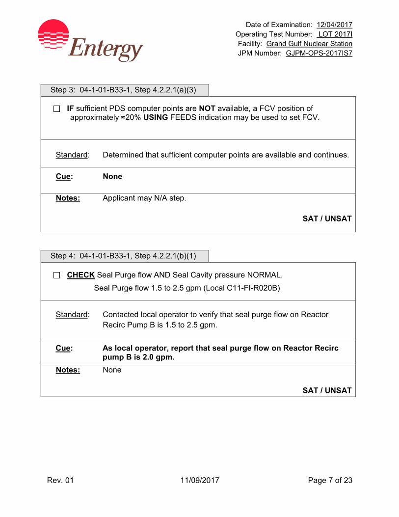
Date of Examination: 12/04/2017 Operating Test Number: LOT 2017I Facility: Grand Gulf Nuclear Station JPM Number: GJPM-OPS-2017IS7
Rev. 01 11/09/2017 Page 7 of 23
Step 3: 04-1-01-B33-1, Step 4.2.2.1(a)(3)
IF sufficient PDS computer points are NOT available, a FCV position of approximately ≈20% USING FEEDS indication may be used to set FCV.
Standard: Determined that sufficient computer points are available and continues.
Cue: None
Notes: Applicant may N/A step.
SAT / UNSAT
Step 4: 04-1-01-B33-1, Step 4.2.2.1(b)(1)
CHECK Seal Purge flow AND Seal Cavity pressure NORMAL. Seal Purge flow 1.5 to 2.5 gpm (Local C11-FI-R020B)
Standard: Contacted local operator to verify that seal purge flow on Reactor Recirc Pump B is 1.5 to 2.5 gpm.
Cue: As local operator, report that seal purge flow on Reactor Recirc pump B is 2.0 gpm.
Notes: None
SAT / UNSAT

Date of Examination: 12/04/2017 Operating Test Number: LOT 2017I Facility: Grand Gulf Nuclear Station JPM Number: GJPM-OPS-2017IS7
Rev. 01 11/09/2017 Page 8 of 23
Step 5: 04-1-01-B33-1, Step 4.2.2.1(b)(2)
CHECK #1 Seal Cavity pressure slightly higher than reactor pressure.
Standard: Checked seal cavity #1 (B33-R603B on P680) pressure is slightly
higher than reactor pressure.
Cue: None
Notes: 1H13-P680 section 3B
Reactor pressure may be obtained from multiple locations any one is acceptable.
SAT / UNSAT Step 6: 04-1-01-B33-1, Step 4.2.2.1(b)(3)
CHECK #2 Seal Cavity pressure indicates approximately half the value of #1 seal cavity pressure.
Standard: Checked seal cavity # 2 pressure is approximately half the value of the
# 1 seal cavity pressure by observing indicators B33-R603B (Seal 1 pressure) and B33-R602B (Seal 2 pressure) on P680.
Cue: None
Notes: 1H13-P680 section 3B
SAT / UNSAT
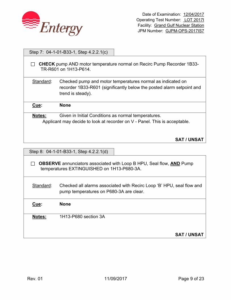
Date of Examination: 12/04/2017 Operating Test Number: LOT 2017I Facility: Grand Gulf Nuclear Station JPM Number: GJPM-OPS-2017IS7
Rev. 01 11/09/2017 Page 9 of 23
Step 7: 04-1-01-B33-1, Step 4.2.2.1(c)
CHECK pump AND motor temperature normal on Recirc Pump Recorder 1B33-TR-R601 on 1H13-P614.
Standard: Checked pump and motor temperatures normal as indicated on recorder 1B33-R601 (significantly below the posted alarm setpoint and trend is steady).
Cue: None
Notes: Given in Initial Conditions as normal temperatures. Applicant may decide to look at recorder on V - Panel. This is acceptable.
SAT / UNSAT Step 8: 04-1-01-B33-1, Step 4.2.2.1(d)
OBSERVE annunciators associated with Loop B HPU, Seal flow, AND Pump temperatures EXTINGUISHED on 1H13-P680-3A.
Standard: Checked all alarms associated with Recirc Loop ‘B’ HPU, seal flow and
pump temperatures on P680-3A are clear.
Cue: None
Notes: 1H13-P680 section 3A
SAT / UNSAT
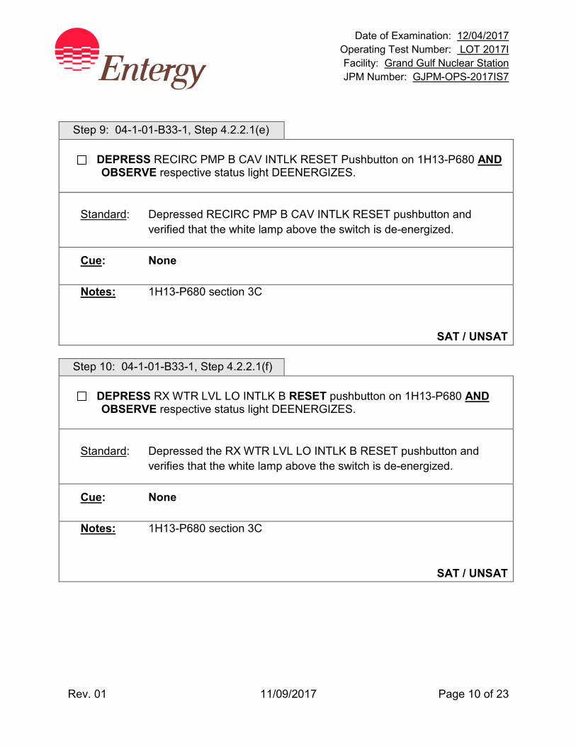
Date of Examination: 12/04/2017 Operating Test Number: LOT 2017I Facility: Grand Gulf Nuclear Station JPM Number: GJPM-OPS-2017IS7
Rev. 01 11/09/2017 Page 10 of 23
Step 9: 04-1-01-B33-1, Step 4.2.2.1(e)
DEPRESS RECIRC PMP B CAV INTLK RESET Pushbutton on 1H13-P680 AND OBSERVE respective status light DEENERGIZES.
Standard: Depressed RECIRC PMP B CAV INTLK RESET pushbutton and
verified that the white lamp above the switch is de-energized.
Cue: None
Notes: 1H13-P680 section 3C
SAT / UNSAT Step 10: 04-1-01-B33-1, Step 4.2.2.1(f)
DEPRESS RX WTR LVL LO INTLK B RESET pushbutton on 1H13-P680 AND OBSERVE respective status light DEENERGIZES.
Standard: Depressed the RX WTR LVL LO INTLK B RESET pushbutton and
verifies that the white lamp above the switch is de-energized.
Cue: None
Notes: 1H13-P680 section 3C
SAT / UNSAT
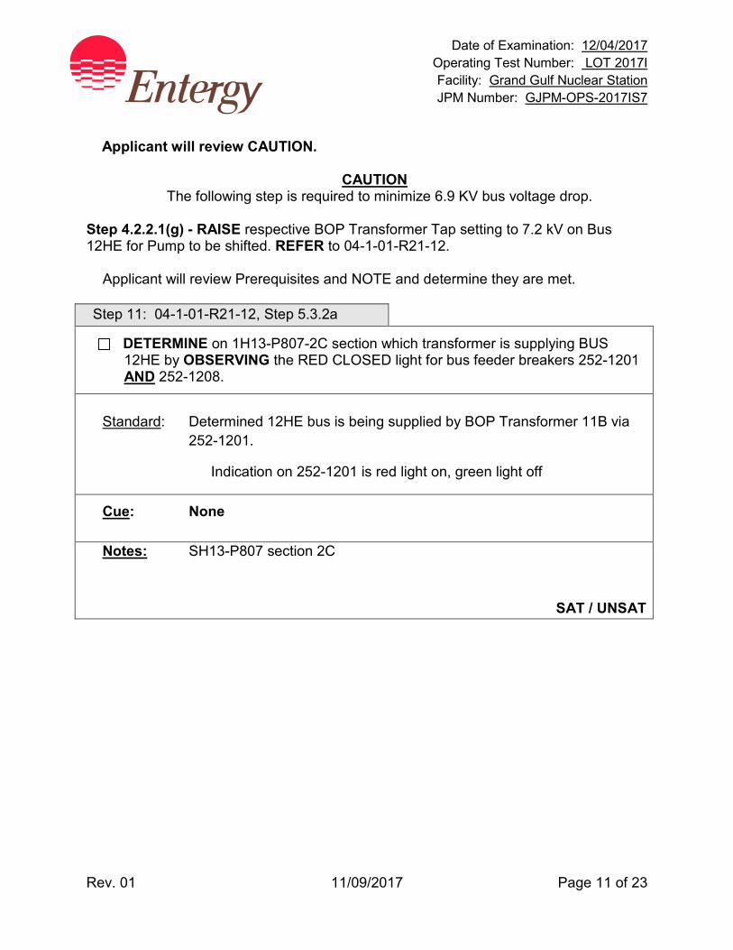
Date of Examination: 12/04/2017 Operating Test Number: LOT 2017I Facility: Grand Gulf Nuclear Station JPM Number: GJPM-OPS-2017IS7
Rev. 01 11/09/2017 Page 11 of 23
Applicant will review CAUTION.
CAUTION The following step is required to minimize 6.9 KV bus voltage drop.
Step 4.2.2.1(g) - RAISE respective BOP Transformer Tap setting to 7.2 kV on Bus 12HE for Pump to be shifted. REFER to 04-1-01-R21-12.
Applicant will review Prerequisites and NOTE and determine they are met.
Step 11: 04-1-01-R21-12, Step 5.3.2a
DETERMINE on 1H13-P807-2C section which transformer is supplying BUS 12HE by OBSERVING the RED CLOSED light for bus feeder breakers 252-1201 AND 252-1208.
Standard: Determined 12HE bus is being supplied by BOP Transformer 11B via
252-1201.
Indication on 252-1201 is red light on, green light off
Cue: None
Notes: SH13-P807 section 2C
SAT / UNSAT
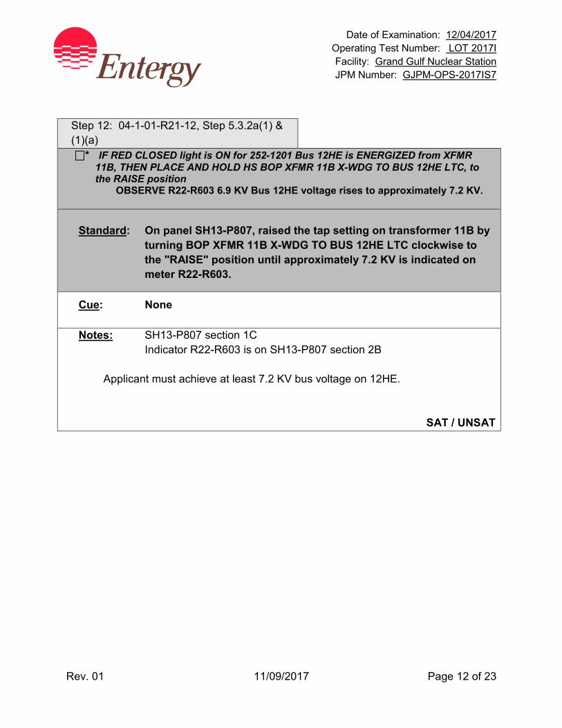
Date of Examination: 12/04/2017 Operating Test Number: LOT 2017I Facility: Grand Gulf Nuclear Station JPM Number: GJPM-OPS-2017IS7
Rev. 01 11/09/2017 Page 12 of 23
Step 12: 04-1-01-R21-12, Step 5.3.2a(1) & (1)(a)
* IF RED CLOSED light is ON for 252-1201 Bus 12HE is ENERGIZED from XFMR 11B, THEN PLACE AND HOLD HS BOP XFMR 11B X-WDG TO BUS 12HE LTC, to the RAISE position
OBSERVE R22-R603 6.9 KV Bus 12HE voltage rises to approximately 7.2 KV. Standard: On panel SH13-P807, raised the tap setting on transformer 11B by
turning BOP XFMR 11B X-WDG TO BUS 12HE LTC clockwise to the "RAISE" position until approximately 7.2 KV is indicated on meter R22-R603.
Cue: None
Notes: SH13-P807 section 1C Indicator R22-R603 is on SH13-P807 section 2B
Applicant must achieve at least 7.2 KV bus voltage on 12HE.
SAT / UNSAT

Date of Examination: 12/04/2017 Operating Test Number: LOT 2017I Facility: Grand Gulf Nuclear Station JPM Number: GJPM-OPS-2017IS7
Rev. 01 11/09/2017 Page 13 of 23
Step 13: 04-1-01-R21-12, Step 5.3.2a(1)(b) & (c)
PLACE HS BOP XFMR 11B X-WDG TO BUS 12HE LTC, to the AUTO position. ENSURE R22-R603 6.9 KV BUS 12HE voltage stabilizes at approximately 7.2 KV.
Standard: Placed HS BOP XFMR 11B X-WDG TO BUS 12HE LTC, to the AUTO
position. Observed Bus 12HE voltage stable at ≈7.2 KV.
Cue: None
Notes: SH13-P807 section 1C Indicator R22-R603 is on SH13-P807 section 2B
SAT / UNSAT
Step 14: 04-1-01-B33-1, Step 4.2.2.1(h)
CHEM / R P NOTIFY Chemistry AND Radiation Protection of the possibility of a crud burst AS A RESULT OF the Recirculation pump speed transfer.[O-24]
Standard: Chemistry and Radiation Protection notified that a Recirc Pump is to be
started which may cause a crud burst.
Cue: RP and Chemistry are notified.
Notes: Given in Initial Conditions
SAT / UNSAT
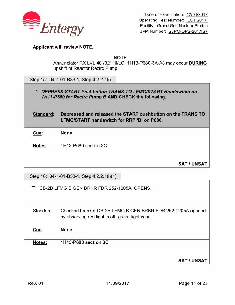
Date of Examination: 12/04/2017 Operating Test Number: LOT 2017I Facility: Grand Gulf Nuclear Station JPM Number: GJPM-OPS-2017IS7
Rev. 01 11/09/2017 Page 14 of 23
Applicant will review NOTE.
NOTE Annunciator RX LVL 40”/32” HI/LO, 1H13-P680-3A-A3 may occur DURING upshift of Reactor Recirc Pump.
Step 15: 04-1-01-B33-1, Step 4.2.2.1(i)
* DEPRESS START Pushbutton TRANS TO LFMG/START Handswitch on 1H13-P680 for Recirc Pump B AND CHECK the following.
Standard: Depressed and released the START pushbutton on the TRANS TO
LFMG/START handswitch for RRP ‘B’ on P680.
Cue: None
Notes: 1H13-P680 section 3C
SAT / UNSAT Step 16: 04-1-01-B33-1, Step 4.2.2.1(i)(1)
CB-2B LFMG B GEN BRKR FDR 252-1205A, OPENS.
Standard: Checked breaker CB-2B LFMG B GEN BRKR FDR 252-1205A opened
by observing red light is off, green light is on.
Cue: None
Notes: 1H13-P680 section 3C
SAT / UNSAT
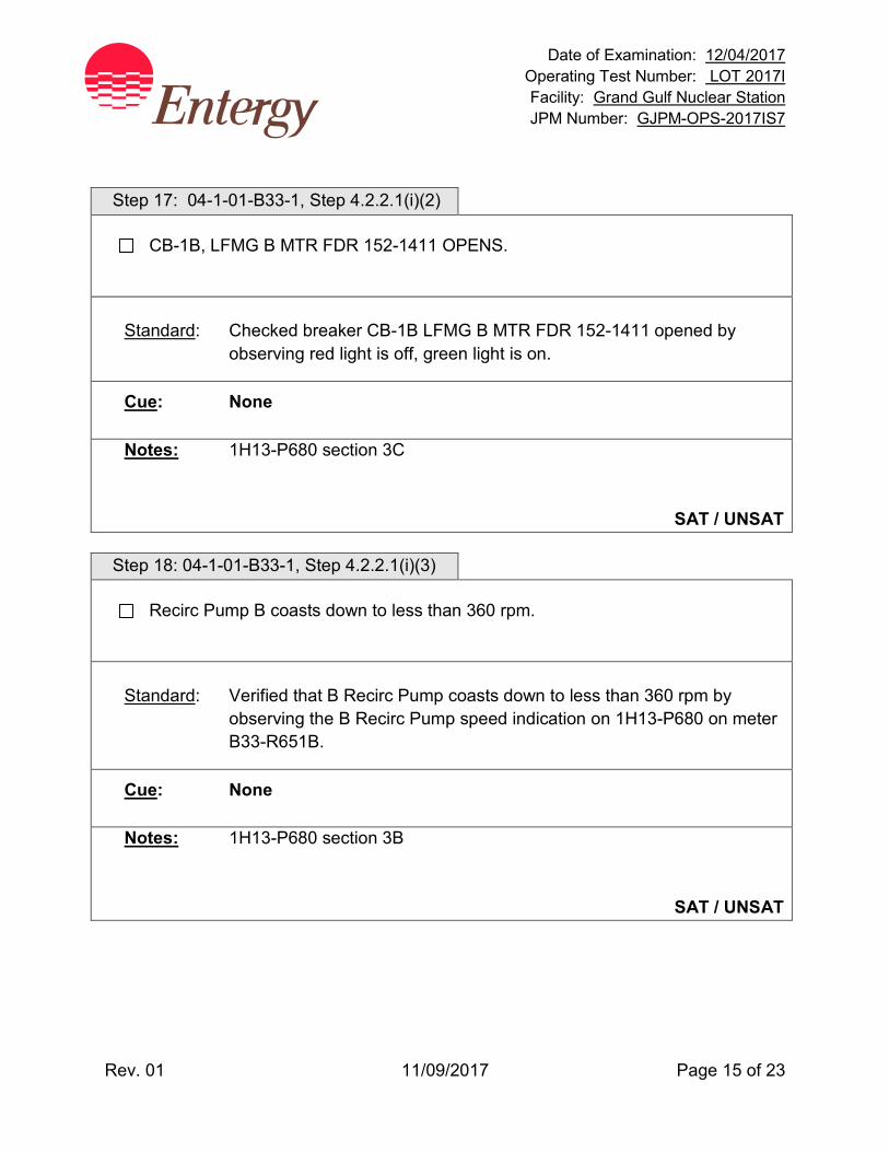
Date of Examination: 12/04/2017 Operating Test Number: LOT 2017I Facility: Grand Gulf Nuclear Station JPM Number: GJPM-OPS-2017IS7
Rev. 01 11/09/2017 Page 15 of 23
Step 17: 04-1-01-B33-1, Step 4.2.2.1(i)(2)
CB-1B, LFMG B MTR FDR 152-1411 OPENS.
Standard: Checked breaker CB-1B LFMG B MTR FDR 152-1411 opened by
observing red light is off, green light is on.
Cue: None
Notes: 1H13-P680 section 3C
SAT / UNSAT Step 18: 04-1-01-B33-1, Step 4.2.2.1(i)(3)
Recirc Pump B coasts down to less than 360 rpm.
Standard: Verified that B Recirc Pump coasts down to less than 360 rpm by
observing the B Recirc Pump speed indication on 1H13-P680 on meter B33-R651B.
Cue: None
Notes: 1H13-P680 section 3B
SAT / UNSAT
Date of Examination: 12/04/2017 Operating Test Number: LOT 2017I Facility: Grand Gulf Nuclear Station JPM Number: GJPM-OPS-2017IS7
Rev. 01 11/09/2017 Page 16 of 23
Step 19: 04-1-01-B33-1, Step 4.2.2.1(j)
WHEN pump speed lowers below 360 rpm, CHECK that CB-5B, RECIRC PUMP B FDR, 252-1205 CLOSED.
Standard: Observed that breaker CB-5B DID NOT close, as indicated by red light
off, green light on.
Cue: None
Notes: 1H13-P680 section 3C
SAT / UNSAT
Recirc Pump B has tripped to OFF.

Date of Examination: 12/04/2017 Operating Test Number: LOT 2017I Facility: Grand Gulf Nuclear Station JPM Number: GJPM-OPS-2017IS7
Rev. 01 11/09/2017 Page 17 of 23
Alternate Path begins with the next step designated by “AP”. Enters Alarm Response Instruction 04-1-02-1H13-P680 AP Step 20: ARI 04-1-02-1H13-P680-3A-D9
Recognizes Start Sequence Failure on Reactor Recirc Pump B.
Standard: Observed the following:
1) CB-5B failed to close as indicated by red status light off, green status light on. 2) Annunciator "RECIRC PMP B AUTO XFER INC/CONT PWR LOSS (P680-3A-
D9) actuated. 3) Breaker CB-2B is open as indicated by red status light off, green status light on. 4) Breaker CB-1B is open as indicated by red status light off, green status light on.
Cue: When applicant reports trip of Recirc Pump B, direct applicant to
perform actions of the appropriate procedure
Notes: Alarm Response Instruction Immediate actions will direct entry into ONEP 05-1-02-III-3, Reduction in Recirculation System Flow Rate.
SAT / UNSAT
Date of Examination: 12/04/2017 Operating Test Number: LOT 2017I Facility: Grand Gulf Nuclear Station JPM Number: GJPM-OPS-2017IS7
Rev. 01 11/09/2017 Page 18 of 23
Enters 05-1-02-III-3, Reduction in Recirculation System Flowrate ONEP AP Step 21: 05-1-02-III-3 Step 2.1
IF ANY of the following conditions of 2.1.1 OR 2.1.2 exist, THEN IMMEDIATELY PLACE the reactor mode switch in the SHUTDOWN position.
2.1.1 When operating in the OPRM Armed Region of Figure 1 or Figure 2, thermal hydraulic instability is detected by: a. At least 2 of the following 4 alarms:
Annunciators “APRM CH 1(2)(3)(4) UPSC TRIP/OPRM TRIP/INOP” AND The corresponding two computer points in alarm: C51NC065 (NC066, NC067, NC068), “APRM 1 (2)(3)(4) OPRM TRIP” OR
b. Thermal Hydraulic Instability symptoms being observed on neutron instrumentation.
2.1.2 No recirculation loops are in operation with the Reactor Mode switch in RUN position.
Standard: Verified that none of the conditions, listed in the Immediate Operator
Actions, exist and placing the mode switch to SHUTDOWN is NOT required. Continued to subsequent actions.
Cue: None
Notes: Continue to Subsequent Actions
SAT / UNSAT
Date of Examination: 12/04/2017 Operating Test Number: LOT 2017I Facility: Grand Gulf Nuclear Station JPM Number: GJPM-OPS-2017IS7
Rev. 01 11/09/2017 Page 19 of 23
AP Step 22: 05-1-02-III-3, Step 3.1
MONITOR APRMs, LPRMs, SRM period meters, AND OPRM Computer Trends. 3.1.1 IF operating in any region of reduced core flow of Figure 1 OR Figure 2,
THEN the following annunciator alarm is indicative of possible onset of thermal hydraulic instability:
“APRM UPSC/OPRM ALM” (located 1H13-P680-5A-B10)
3.1.2 IF operating in any region of reduced core flow of Figure 1 or Figure 2 AND thermal hydraulic instability is observed, THEN IMMEDIATELY SCRAM the Reactor.
Standard: Monitored nuclear instrumentation and IF THI is observed then
immediately scrams the reactor. (THI will not occur.)
Cue: As CRS, inform applicant that another operator will have the responsibilities as THI watch, continue with immediate and subsequent actions.
Notes: Thermal Hydraulic Instability (THI) will not occur.
SAT / UNSAT
Date of Examination: 12/04/2017 Operating Test Number: LOT 2017I Facility: Grand Gulf Nuclear Station JPM Number: GJPM-OPS-2017IS7
Rev. 01 11/09/2017 Page 20 of 23
Applicant will review CAUTION.
CAUTION Operation in the MELLLA+ region is prohibited in single Recirc pump loop operation. Step 3.5 is appropriate step. AP Step 23: 05-1-02-III-3, Step 3.5
* IF one Recirculation pump has stopped, THEN PERFORM the following: CLOSE RECIRC PMP B DISCH VLV B33-F067B in the affected loop.
Standard: B33-F067B RECIRC PMP B DISCH VLV is closed Indicated by red light off, green light on.
Cue: JPM has been completed
Notes: None
SAT / UNSAT
EVALUATOR CUE APPLICANT JPM IS TERMINATED WHEN B33-F067B IS CLOSED.

Date of Examination: 12/04/2017 Operating Test Number: LOT 2017I Facility: Grand Gulf Nuclear Station JPM Number: GJPM-OPS-2017IS7
Rev. 01 11/09/2017 Page 21 of 23
Task Standard(s):
• Closed Recirc Loop B FCV to MIN ED position
• Raised Bus 12HE voltage to 7.2 KV using BOP Transformer 11B tap changer
• Depressed TRANS TO LFMG/START pushbutton for Reactor Recirc Pump B
• When Recirc Pump B is tripped closed B33-F067B, RECIRC PMP B DISCH VLV
SAT / UNSAT Remember to record stop time
Date of Examination: 12/04/2017 Operating Test Number: LOT 2017I Facility: Grand Gulf Nuclear Station JPM Number: GJPM-OPS-2017IS7
Rev. 01 11/09/2017 Page 22 of 23
Follow-Up Questions & Answers:
Comments:
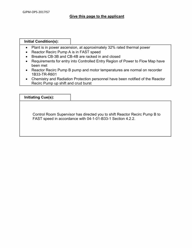
GJPM-OPS-2017IS7
Give this page to the applicant
Initial Condition(s): • Plant is in power ascension, at approximately 32% rated thermal power • Reactor Recirc Pump A is in FAST speed • Breakers CB-3B and CB-4B are racked in and closed • Requirements for entry into Controlled Entry Region of Power to Flow Map have
been met • Reactor Recirc Pump B pump and motor temperatures are normal on recorder
1B33-TR-R601 • Chemistry and Radiation Protection personnel have been notified of the Reactor
Recirc Pump up shift and crud burst
Initiating Cue(s):
Control Room Supervisor has directed you to shift Reactor Recirc Pump B to FAST speed in accordance with 04-1-01-B33-1 Section 4.2.2.

Date of Examination: 12/04/2017 Operating Test Number: GGNS 12-2017
Facility: Grand Gulf Nuclear Station JPM Number: GJPM-OPS-2017IP1
Rev. 03 12/01/2017 Page 1 of 21
2017I P1 GGNS
2017 NRC Operating Test Job Performance Measure
JPM Number: GJPM-OPS-2017IP1 JPM Title: Align SP Cooling from RSP Facility Number: __GJPM-OPS-C6101 rev 6 (If Bank or Modified from Bank)
JPM Attributes:
New Modified Direct from bank
Time Critical Alternate Path Validation Time: 15 min
Prepared By: Michael Rasch 11/08/2017 Exam Developer Date
Ops Review: Robert Brinkman 11/08/2017 1st Validation by Ops Rep or Ops Validation Crew Date
Validated By: Benny White \ Chase Miller 11/08/2017 2nd Validation by Ops Validation Crew Date
Approved By: Ricky Liddell 11/08/2017 Project Lead or Exam Team Lead Date

Date of Examination: 12/04/2017 Operating Test Number: GGNS 12-2017
Facility: Grand Gulf Nuclear Station JPM Number: GJPM-OPS-2017IP1
Rev. 03 12/01/2017 Page 2 of 21
Align SP Cooling from RSP
Time Critical Alternate Path Validation Time: 15 Min
Setting: Plant Type: RO/SRO Task: CRO-C61-OFFNORM-1 CRO-C61-OFFNORM-1.9 CRO-E12-NORMAL-19 CRO-P41-NORMAL-1 K&A: 219000 A4.01 (3.8/3.7); A4.02 (3.7/3.5); A4.05 (3.4/3.4) 295016 AK2.01 (4.4/4.5); AK3.03 (3.5/3.7) 295013 AA1.01 (3.9/3.9) Safety Function: 5 – Containment Integrity PSA Applicability: Operator Action Importance to Core Damage Frequency
rank 9 10CFR 55.45(a) (2);(8); (12) Performance: Simulate Reference(s): 05-1-02-II-1, rev. 49, Shutdown from Remote Shutdown
Panels Attachment IX, RHR A Suppression Pool Cooling Attachment X, RHR B Suppression Pool Cooling Handout(s): 05-1-02-II-1 Attachment IX & not given initially Attachment X # Manipulations: 20 # Critical Steps: 16 Low Power: YES Emergency/Abnormal: YES RCA entry: No Engineered Safety Function: No Simulator Setup/Required Plant Conditions:
• Remote Shutdown Panel is accessible Safety Concerns:
• Wear appropriate personal protective equipment • DO NOT bump OR operate controls on the Remote Shutdown Panels
.
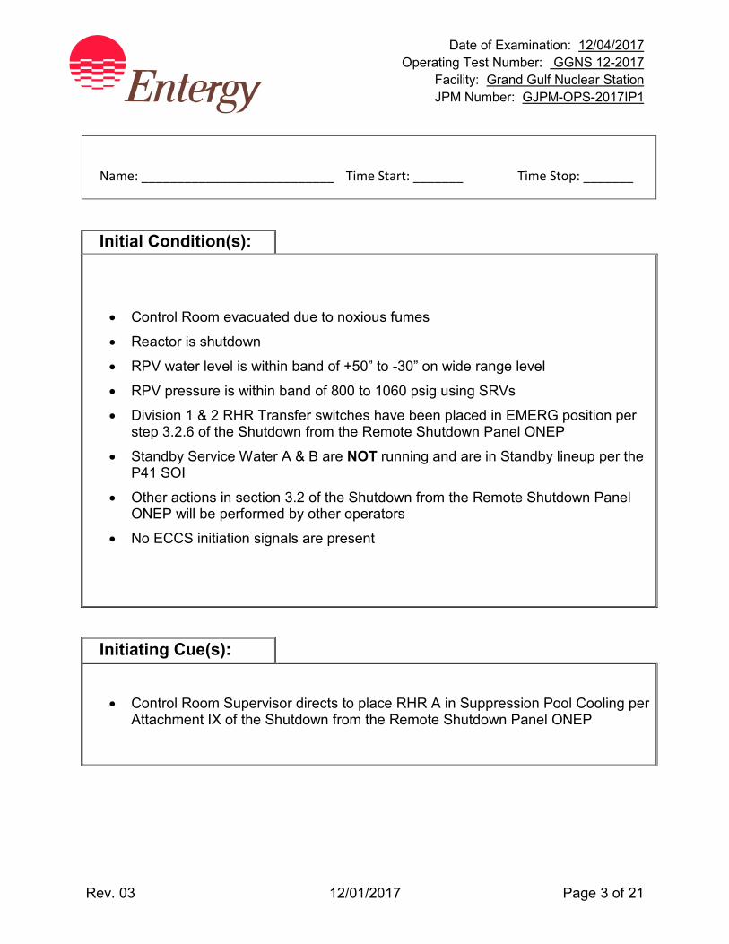
Date of Examination: 12/04/2017 Operating Test Number: GGNS 12-2017
Facility: Grand Gulf Nuclear Station JPM Number: GJPM-OPS-2017IP1
Rev. 03 12/01/2017 Page 3 of 21
Name: ___________________________ Time Start: _______ Time Stop: _______
Initial Condition(s):
• Control Room evacuated due to noxious fumes
• Reactor is shutdown
• RPV water level is within band of +50” to -30” on wide range level
• RPV pressure is within band of 800 to 1060 psig using SRVs
• Division 1 & 2 RHR Transfer switches have been placed in EMERG position per step 3.2.6 of the Shutdown from the Remote Shutdown Panel ONEP
• Standby Service Water A & B are NOT running and are in Standby lineup per the P41 SOI
• Other actions in section 3.2 of the Shutdown from the Remote Shutdown Panel ONEP will be performed by other operators
• No ECCS initiation signals are present
Initiating Cue(s):
• Control Room Supervisor directs to place RHR A in Suppression Pool Cooling per Attachment IX of the Shutdown from the Remote Shutdown Panel ONEP
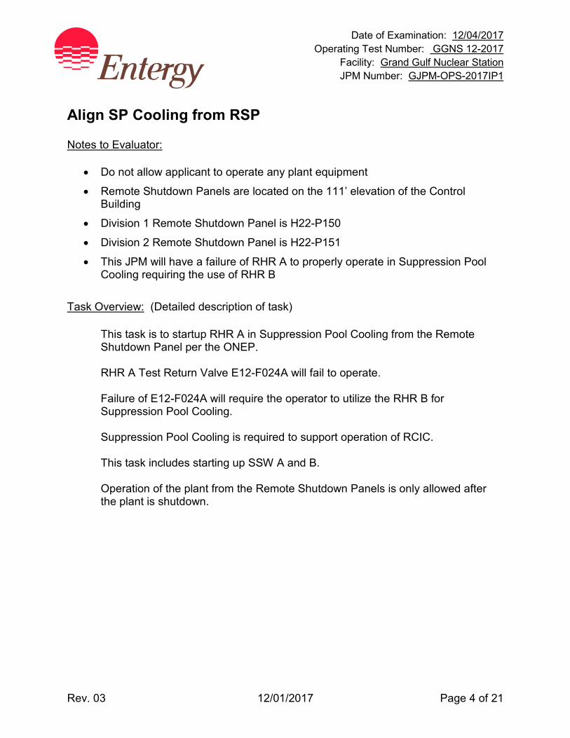
Date of Examination: 12/04/2017 Operating Test Number: GGNS 12-2017
Facility: Grand Gulf Nuclear Station JPM Number: GJPM-OPS-2017IP1
Rev. 03 12/01/2017 Page 4 of 21
Align SP Cooling from RSP Notes to Evaluator:
• Do not allow applicant to operate any plant equipment
• Remote Shutdown Panels are located on the 111’ elevation of the Control Building
• Division 1 Remote Shutdown Panel is H22-P150
• Division 2 Remote Shutdown Panel is H22-P151
• This JPM will have a failure of RHR A to properly operate in Suppression Pool Cooling requiring the use of RHR B
Task Overview: (Detailed description of task)
This task is to startup RHR A in Suppression Pool Cooling from the Remote Shutdown Panel per the ONEP. RHR A Test Return Valve E12-F024A will fail to operate. Failure of E12-F024A will require the operator to utilize the RHR B for Suppression Pool Cooling. Suppression Pool Cooling is required to support operation of RCIC. This task includes starting up SSW A and B. Operation of the plant from the Remote Shutdown Panels is only allowed after the plant is shutdown.
Date of Examination: 12/04/2017 Operating Test Number: GGNS 12-2017
Facility: Grand Gulf Nuclear Station JPM Number: GJPM-OPS-2017IP1
Rev. 03 12/01/2017 Page 5 of 21
Align SP Cooling from RSP ONLY GIVE THE APPLICANT ATTACHMENT IX FOR RHR A. Critical steps are shaded, bolded, italicized, and denoted by an (*) NOTE: The sequence of the following steps is critical unless otherwise
noted.
Step 1: 05-1-02-II-1 Att. IX, Step a (1)
CHECK OPEN/OPEN 1P41-F068A SSW OUTL FM RHR HX A VLV [SSD] (HS-M008A)
Standard: Checked open P41-F068A, SSW OUTL FM RHR HX A VLV.
Indication red light on, green light off
Cue: Red light on, green light off.
Notes: 1H22-P150
SAT / UNSAT
Date of Examination: 12/04/2017 Operating Test Number: GGNS 12-2017
Facility: Grand Gulf Nuclear Station JPM Number: GJPM-OPS-2017IP1
Rev. 03 12/01/2017 Page 6 of 21
Step 2: 05-1-02-II-1 Att. IX, Step a (2)
* START 1P41-C001A, SSW PMP A [SSD] (HS-M001A)
Standard: Started SSW Pump A. Indication red light on, green light off
Cue: Red light on, green light off.
Notes: 1H22-P150
SAT / UNSAT
Step 3: 05-1-02-II-1 Att. IX, Step a (3)
* OPEN 1P41-F001A SSW PMP A DISCH VLV [SSD] (HS-M002A)
Standard: Opened P41-F001A, SSW PMP A DISCH VLV.
Indication red light on, green light off
Cue: Red light on, green light off.
Notes: 1H22-P150
SAT / UNSAT
Date of Examination: 12/04/2017 Operating Test Number: GGNS 12-2017
Facility: Grand Gulf Nuclear Station JPM Number: GJPM-OPS-2017IP1
Rev. 03 12/01/2017 Page 7 of 21
Step 4: 05-1-02-II-1 Att. IX, Step a (4)
* OPEN 1P41-F014A SSW INL TO RHR HX A VLV [SSD] (HS-M007A)
Standard: Opened P41-F014A SSW INL TO RHR HX A VLV.
Indication red light on, green light off
Cue: Red light on, green light off.
Notes: 1H22-P150
SAT / UNSAT
Step 5: 05-1-02-II-1 Att. IX, Step a (5)
* OPEN 1P41-F005A SSW Loop A RTN TO CLG TWR A [SSD] (HS-M010A)
Standard: Opened P41-F005A, SSW Loop A RTN TO CLG TWR A. Handswitch is held in OPEN position until indication red light
on, green light off
Cue: Red light on, green light off.
Notes: This is a JOG handswitch.
1H22-P150
SAT / UNSAT

Date of Examination: 12/04/2017 Operating Test Number: GGNS 12-2017
Facility: Grand Gulf Nuclear Station JPM Number: GJPM-OPS-2017IP1
Rev. 03 12/01/2017 Page 8 of 21
Step 6: 05-1-02-II-1 Att. IX, Step a (6)
* VERIFY CLOSED/CLOSE 1P41-F006A SSW PMP A RECIRC VLV (HS-M004A)
Standard: Closed P41-F006A, SSW PMP A RECIRC VLV.
Indication green light on, red light off
Cue: Green light on, red light off.
If asked, SSW A flow indicates 11000gpm
Notes: 1H22-P150
SAT / UNSAT
Step 7: 05-1-02-II-1 Att. IX, Step a (7)
START 1P41-C003A, SSW CLG TWR FAN A [SSD] (HS-M011A)
Standard: Started SSW Cooling Tower Fan A. Indication red light on, green light off
Cue: Red light on, green light off
Notes: if not performed, Cooling Tower Fans will auto start when RHR A pump started.
1H22-P150
SAT / UNSAT
Date of Examination: 12/04/2017 Operating Test Number: GGNS 12-2017
Facility: Grand Gulf Nuclear Station JPM Number: GJPM-OPS-2017IP1
Rev. 03 12/01/2017 Page 9 of 21
Step 8: 05-1-02-II-1 Att. IX, Step a (8)
START 1P41-C003B, SSW CLG TWR FAN B [SSD] (HS-M012A)
Standard: Started SSW Cooling Tower Fan B.
Indication red light on, green light off
Cue: Red light on, green light off.
Notes: if not performed, Cooling Tower Fans will auto start when RHR A pump started.
1H22-P150
SAT / UNSAT
Step 9: 05-1-02-II-1 Att. IX, Step b OPEN OR CHECK OPEN the following valves:
(1) 1E12-F004A RHR PMP A SUCT FM SUPP POOL [SSD]. (HS-M202A)
(2) 1E12-F047A RHR HX A INL VLV [SSD]. (HS-M206A)
(3) 1E12-F003A RHR HX A OUTL VLV [SSD]. (HS-M207A)
Standard: Observed the above listed valves are open. Indication red light on, green light off
Cue: All of the valves indicate Red light on, green light off.
Notes: These valves are already in their normal lineup.
1H22-P150
SAT / UNSAT
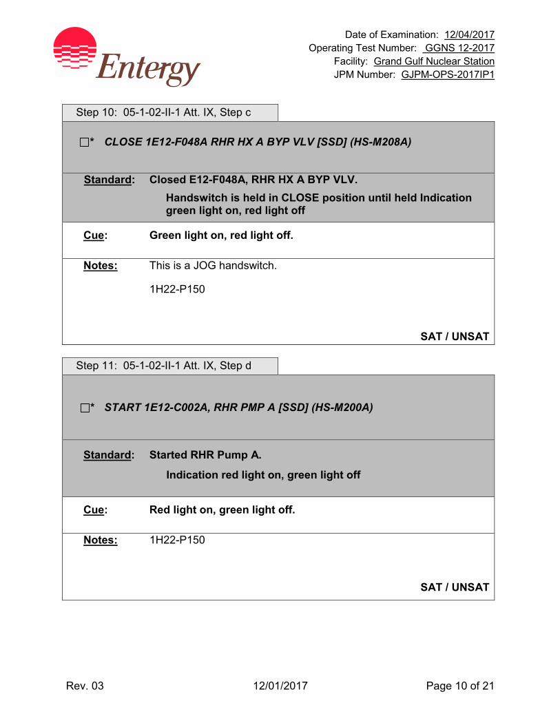
Date of Examination: 12/04/2017 Operating Test Number: GGNS 12-2017
Facility: Grand Gulf Nuclear Station JPM Number: GJPM-OPS-2017IP1
Rev. 03 12/01/2017 Page 10 of 21
Step 10: 05-1-02-II-1 Att. IX, Step c
* CLOSE 1E12-F048A RHR HX A BYP VLV [SSD] (HS-M208A)
Standard: Closed E12-F048A, RHR HX A BYP VLV. Handswitch is held in CLOSE position until held Indication
green light on, red light off
Cue: Green light on, red light off.
Notes: This is a JOG handswitch.
1H22-P150
SAT / UNSAT
Step 11: 05-1-02-II-1 Att. IX, Step d
* START 1E12-C002A, RHR PMP A [SSD] (HS-M200A)
Standard: Started RHR Pump A.
Indication red light on, green light off
Cue: Red light on, green light off.
Notes: 1H22-P150
SAT / UNSAT
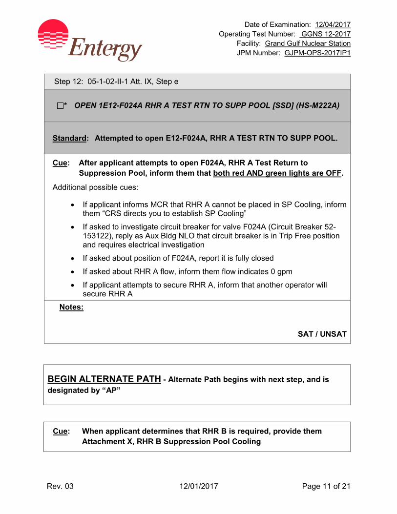
Date of Examination: 12/04/2017 Operating Test Number: GGNS 12-2017
Facility: Grand Gulf Nuclear Station JPM Number: GJPM-OPS-2017IP1
Rev. 03 12/01/2017 Page 11 of 21
Step 12: 05-1-02-II-1 Att. IX, Step e
* OPEN 1E12-F024A RHR A TEST RTN TO SUPP POOL [SSD] (HS-M222A)
Standard: Attempted to open E12-F024A, RHR A TEST RTN TO SUPP POOL.
Cue: After applicant attempts to open F024A, RHR A Test Return to Suppression Pool, inform them that both red AND green lights are OFF.
Additional possible cues:
• If applicant informs MCR that RHR A cannot be placed in SP Cooling, inform them “CRS directs you to establish SP Cooling”
• If asked to investigate circuit breaker for valve F024A (Circuit Breaker 52-153122), reply as Aux Bldg NLO that circuit breaker is in Trip Free position and requires electrical investigation
• If asked about position of F024A, report it is fully closed
• If asked about RHR A flow, inform them flow indicates 0 gpm
• If applicant attempts to secure RHR A, inform that another operator will secure RHR A
Notes:
SAT / UNSAT
BEGIN ALTERNATE PATH - Alternate Path begins with next step, and is designated by “AP”
Cue: When applicant determines that RHR B is required, provide them Attachment X, RHR B Suppression Pool Cooling
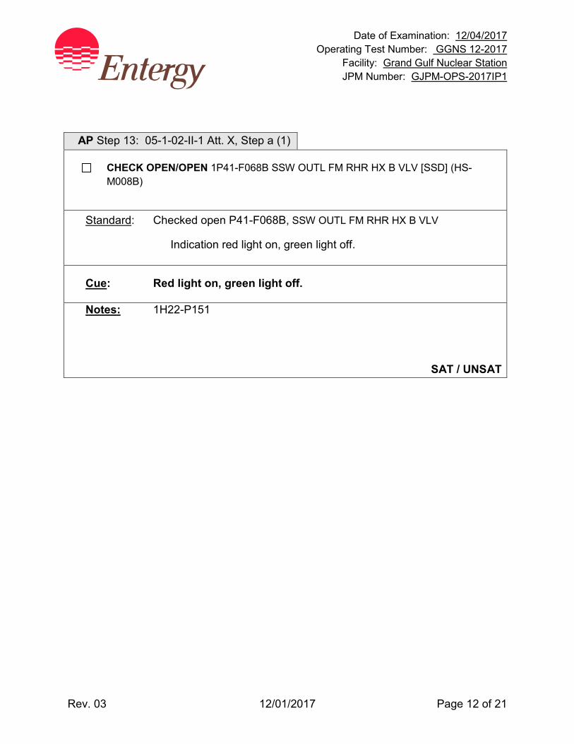
Date of Examination: 12/04/2017 Operating Test Number: GGNS 12-2017
Facility: Grand Gulf Nuclear Station JPM Number: GJPM-OPS-2017IP1
Rev. 03 12/01/2017 Page 12 of 21
AP Step 13: 05-1-02-II-1 Att. X, Step a (1)
CHECK OPEN/OPEN 1P41-F068B SSW OUTL FM RHR HX B VLV [SSD] (HS-M008B)
Standard: Checked open P41-F068B, SSW OUTL FM RHR HX B VLV
Indication red light on, green light off.
Cue: Red light on, green light off.
Notes: 1H22-P151
SAT / UNSAT
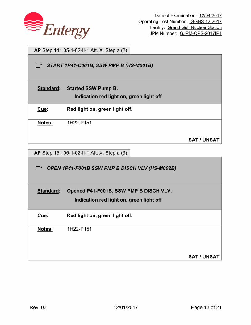
Date of Examination: 12/04/2017 Operating Test Number: GGNS 12-2017
Facility: Grand Gulf Nuclear Station JPM Number: GJPM-OPS-2017IP1
Rev. 03 12/01/2017 Page 13 of 21
AP Step 14: 05-1-02-II-1 Att. X, Step a (2)
* START 1P41-C001B, SSW PMP B (HS-M001B)
Standard: Started SSW Pump B. Indication red light on, green light off
Cue: Red light on, green light off.
Notes: 1H22-P151
SAT / UNSAT
AP Step 15: 05-1-02-II-1 Att. X, Step a (3)
* OPEN 1P41-F001B SSW PMP B DISCH VLV (HS-M002B)
Standard: Opened P41-F001B, SSW PMP B DISCH VLV.
Indication red light on, green light off
Cue: Red light on, green light off.
Notes: 1H22-P151
SAT / UNSAT
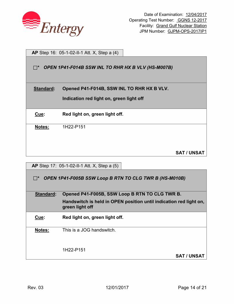
Date of Examination: 12/04/2017 Operating Test Number: GGNS 12-2017
Facility: Grand Gulf Nuclear Station JPM Number: GJPM-OPS-2017IP1
Rev. 03 12/01/2017 Page 14 of 21
AP Step 16: 05-1-02-II-1 Att. X, Step a (4)
* OPEN 1P41-F014B SSW INL TO RHR HX B VLV (HS-M007B)
Standard: Opened P41-F014B, SSW INL TO RHR HX B VLV.
Indication red light on, green light off
Cue: Red light on, green light off.
Notes: 1H22-P151
SAT / UNSAT
AP Step 17: 05-1-02-II-1 Att. X, Step a (5)
* OPEN 1P41-F005B SSW Loop B RTN TO CLG TWR B (HS-M010B)
Standard: Opened P41-F005B, SSW Loop B RTN TO CLG TWR B. Handswitch is held in OPEN position until indication red light on,
green light off
Cue: Red light on, green light off.
Notes: This is a JOG handswitch.
1H22-P151 SAT / UNSAT
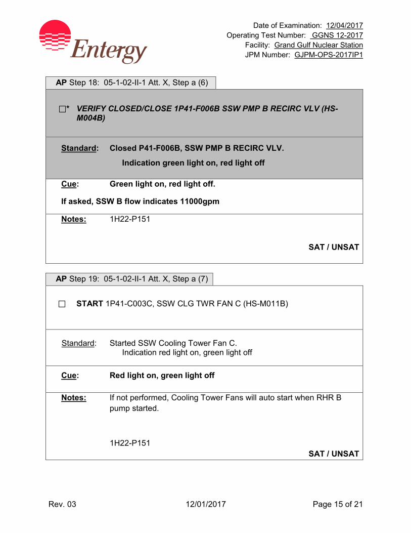
Date of Examination: 12/04/2017 Operating Test Number: GGNS 12-2017
Facility: Grand Gulf Nuclear Station JPM Number: GJPM-OPS-2017IP1
Rev. 03 12/01/2017 Page 15 of 21
AP Step 18: 05-1-02-II-1 Att. X, Step a (6)
* VERIFY CLOSED/CLOSE 1P41-F006B SSW PMP B RECIRC VLV (HS-M004B)
Standard: Closed P41-F006B, SSW PMP B RECIRC VLV.
Indication green light on, red light off
Cue: Green light on, red light off.
If asked, SSW B flow indicates 11000gpm
Notes: 1H22-P151
SAT / UNSAT
AP Step 19: 05-1-02-II-1 Att. X, Step a (7)
START 1P41-C003C, SSW CLG TWR FAN C (HS-M011B)
Standard: Started SSW Cooling Tower Fan C. Indication red light on, green light off
Cue: Red light on, green light off
Notes: If not performed, Cooling Tower Fans will auto start when RHR B pump started.
1H22-P151 SAT / UNSAT

Date of Examination: 12/04/2017 Operating Test Number: GGNS 12-2017
Facility: Grand Gulf Nuclear Station JPM Number: GJPM-OPS-2017IP1
Rev. 03 12/01/2017 Page 16 of 21
AP Step 20: 05-1-02-II-1 Att. X, Step a (8)
START 1P41-C003D, SSW CLG TWR FAN D (HS-M012B)
Standard: Started SSW Cooling Tower Fan D.
Indication red light on, green light off
Cue: Red light on, green light off.
Notes: If not performed, Cooling Tower Fans will auto start when RHR B pump started.
1H22-P151 SAT / UNSAT
AP Step 21: 05-1-02-II-1 Att. X, Step b
OPEN OR CHECK OPEN the following valves:
(1) 1E12-F004B RHR PMP B SUCT FM SUPP POOL. (HS-M202B)
(2) 1E12-F047B RHR HX B INL VLV. (HS-M206B)
(3) 1E12-F003B RHR HX B OUTL VLV. (HS-M207B)
Standard: Observed the above listed valves are open. Indication red light on, green light off
Cue: All of the valves indicate Red light on, green light off.
Notes: These valves are already in their normal lineup
1H22-P151
SAT / UNSAT

Date of Examination: 12/04/2017 Operating Test Number: GGNS 12-2017
Facility: Grand Gulf Nuclear Station JPM Number: GJPM-OPS-2017IP1
Rev. 03 12/01/2017 Page 17 of 21
AP Step 22: 05-1-02-II-1 Att. X, Step c
* CLOSE 1E12-F048B RHR HX B BYP VLV (HS-M208B)
Standard: Closed E12-F048B, RHR HX B BYP VLV. Handswitch is held in CLOSE position until held Indication green
light on, red light off
Cue: Red light off, green light on.
Notes: This is a JOG handswitch.
1H22-P151 SAT / UNSAT
AP Step 23: 05-1-02-II-1 Att. X, Step d
* START 1E12-C002B, RHR PMP B (HS-M200B)
Standard: Started RHR Pump B.
Indication red light on, green light off
Cue: Red light on, green light off.
Notes:
1H22-P151 SAT / UNSAT
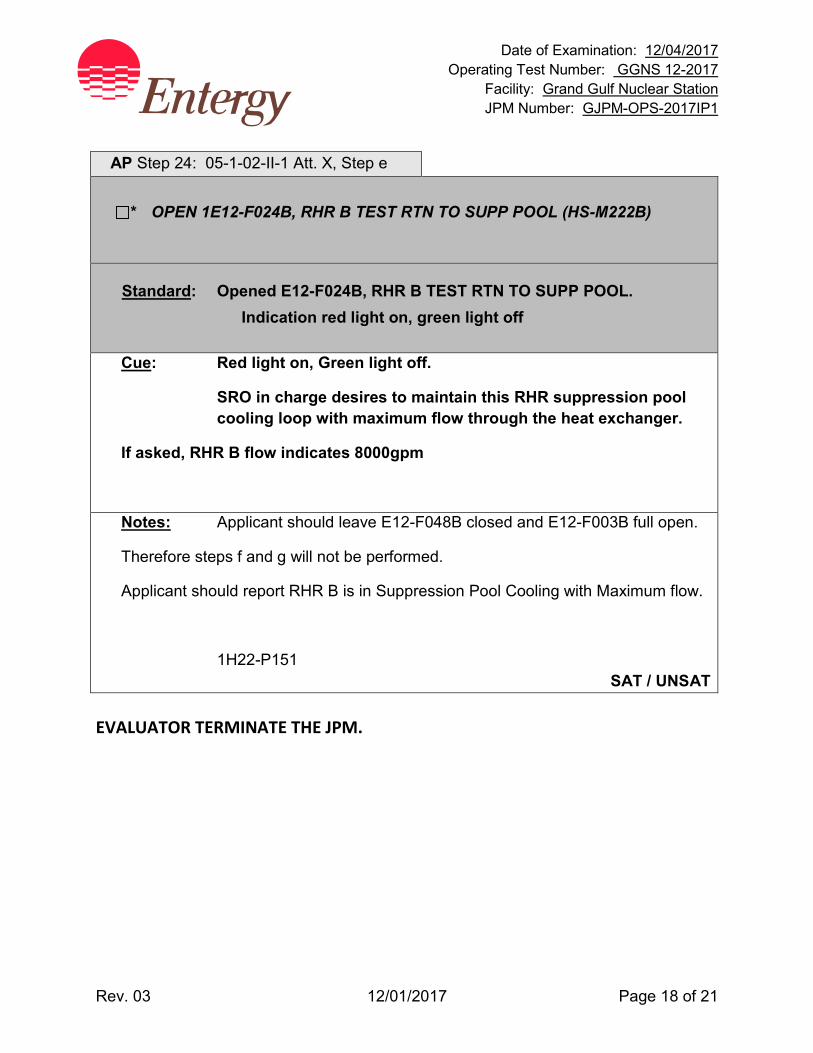
Date of Examination: 12/04/2017 Operating Test Number: GGNS 12-2017
Facility: Grand Gulf Nuclear Station JPM Number: GJPM-OPS-2017IP1
Rev. 03 12/01/2017 Page 18 of 21
AP Step 24: 05-1-02-II-1 Att. X, Step e
* OPEN 1E12-F024B, RHR B TEST RTN TO SUPP POOL (HS-M222B)
Standard: Opened E12-F024B, RHR B TEST RTN TO SUPP POOL. Indication red light on, green light off
Cue: Red light on, Green light off.
SRO in charge desires to maintain this RHR suppression pool cooling loop with maximum flow through the heat exchanger.
If asked, RHR B flow indicates 8000gpm
Notes: Applicant should leave E12-F048B closed and E12-F003B full open.
Therefore steps f and g will not be performed.
Applicant should report RHR B is in Suppression Pool Cooling with Maximum flow.
1H22-P151 SAT / UNSAT
EVALUATOR TERMINATE THE JPM.
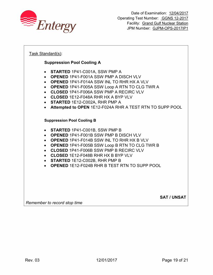
Date of Examination: 12/04/2017 Operating Test Number: GGNS 12-2017
Facility: Grand Gulf Nuclear Station JPM Number: GJPM-OPS-2017IP1
Rev. 03 12/01/2017 Page 19 of 21
Task Standard(s):
Suppression Pool Cooling A
• STARTED 1P41-C001A, SSW PMP A • OPENED 1P41-F001A SSW PMP A DISCH VLV • OPENED 1P41-F014A SSW INL TO RHR HX A VLV • OPENED 1P41-F005A SSW Loop A RTN TO CLG TWR A • CLOSED 1P41-F006A SSW PMP A RECIRC VLV • CLOSED 1E12-F048A RHR HX A BYP VLV • STARTED 1E12-C002A, RHR PMP A • Attempted to OPEN 1E12-F024A RHR A TEST RTN TO SUPP POOL
Suppression Pool Cooling B
• STARTED 1P41-C001B, SSW PMP B • OPENED 1P41-F001B SSW PMP B DISCH VLV • OPENED 1P41-F014B SSW INL TO RHR HX B VLV • OPENED 1P41-F005B SSW Loop B RTN TO CLG TWR B • CLOSED 1P41-F006B SSW PMP B RECIRC VLV • CLOSED 1E12-F048B RHR HX B BYP VLV • STARTED 1E12-C002B, RHR PMP B • OPENED 1E12-F024B RHR B TEST RTN TO SUPP POOL
SAT / UNSAT Remember to record stop time
Date of Examination: 12/04/2017 Operating Test Number: GGNS 12-2017
Facility: Grand Gulf Nuclear Station JPM Number: GJPM-OPS-2017IP1
Rev. 03 12/01/2017 Page 20 of 21
Follow-Up Questions & Answers:
Comments:

GJPM-OPS-2017IP1
Give this page to the applicant
Initial Condition(s):
• Control Room evacuated due to noxious fumes
• Reactor is shutdown
• RPV water level is within band of +50” to -30” on wide range level
• RPV pressure is within band of 800 to 1060 psig using SRVs
• Division 1 & 2 RHR Transfer switches have been placed in EMERG position per step 3.2.6 of the Shutdown from the Remote Shutdown Panel ONEP
• Standby Service Water A & B are NOT running and are in Standby lineup per the P41 SOI
• Other actions in section 3.2 of the Shutdown from the Remote Shutdown Panel ONEP will be performed by other operators
• No ECCS initiation signals are present
Initiating Cue(s):
• Control Room Supervisor directs to place RHR A in Suppression Pool Cooling per Attachment IX of the Shutdown from the Remote Shutdown Panel ONEP

Date of Examination: 12/04/2017 Operating Test Number: GGNS 12-2017
Facility: Grand Gulf Nuclear Station JPM Number: GJPM-OPS-2017IP2
Rev 01 11/07/2017 Page 1 of 13
2017I P2 GGNS
2017 NRC Operating Test Job Performance Measure
JPM Number: GJPM-OPS-2017IP2 JPM Title: Install N2 Bottles on ADS Air Supply
Facility Number: __GJPM-OPS-EOP07 (If Bank or Modified from Bank)
JPM Attributes:
New Modified Direct from bank
Time Critical Alternate Path Validation Time: 20 min
Prepared By: Michael Rasch 11/07/2017 Exam Developer Date
Ops Review: Robert Brinkman 11/07/2017 1st Validation by Ops Rep or Ops Validation Crew Date
Validated By: Benny White \ Chase Miller 11/07/2017 2nd Validation by Ops Validation Crew Date
Approved By: Ricky Liddell 11/07/2017 Project Lead or Exam Team Lead Date
Date of Examination: 12/04/2017 Operating Test Number: GGNS 12-2017
Facility: Grand Gulf Nuclear Station JPM Number: GJPM-OPS-2017IP2
Rev 01 11/07/2017 Page 2 of 13
Install N2 Bottles on ADS Air Supply
Time Critical Alternate Path Validation Time: 20 Min
Setting: Plant (Inside RCA) Type: NLO/RO/SRO Task: GGNS-AON-EP-EMERGENCY-2 K&A: 218000 A2.03 (3.4/3.6) 295019 AA1.01 (3.5/3.3) Safety Function: 3 – Reactor Pressure Control PSA Applicability: Operator Action Importance to Core Damage Frequency Rank 4 10CFR 55.45(a) (7); (12) Performance: Simulate Reference(s): 05-S-01-EP-1/Att. 7 Rev. 36, Emergency/Severe Accident
Procedure Support Documents; Att. 7 Defeating Containment and Drywell Instrument Air Isolation Interlocks
Handout(s): 05-S-01-EP-1/Att. 7 marked up with step 2.4.1 complete # Manipulations: 6 # Critical Steps: 5 Low Power: YES Emergency/Abnormal: YES RCA entry: YES Engineered Safety Function: No Previous 2 NRC exams December 2014 for RO Applicants (not in Previous 2 NRC Exams for SRO Applicants) Plant Industry Experience 2003 Reactor Scram due to loss of grid Simulator Setup/Required Plant Conditions:
• Area 9, elevation 139’ and area 9, elevation 166’ are accessible Safety Concerns:
• Wear appropriate personal protective equipment • NO CLIMBING. Point up or down while you explain what you are going to do • Beware of radiological areas • Area 9 elevation 139’ is a high noise area - hearing protection required
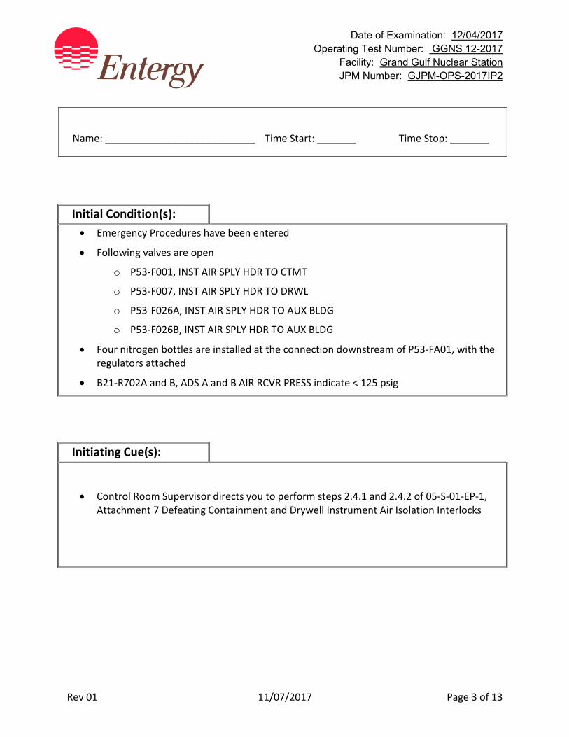
Date of Examination: 12/04/2017 Operating Test Number: GGNS 12-2017
Facility: Grand Gulf Nuclear Station JPM Number: GJPM-OPS-2017IP2
Rev 01 11/07/2017 Page 3 of 13
Name: ___________________________ Time Start: _______ Time Stop: _______
Initial Condition(s): • Emergency Procedures have been entered
• Following valves are open
o P53-F001, INST AIR SPLY HDR TO CTMT
o P53-F007, INST AIR SPLY HDR TO DRWL
o P53-F026A, INST AIR SPLY HDR TO AUX BLDG
o P53-F026B, INST AIR SPLY HDR TO AUX BLDG
• Four nitrogen bottles are installed at the connection downstream of P53-FA01, with the regulators attached
• B21-R702A and B, ADS A and B AIR RCVR PRESS indicate < 125 psig
Initiating Cue(s):
• Control Room Supervisor directs you to perform steps 2.4.1 and 2.4.2 of 05-S-01-EP-1, Attachment 7 Defeating Containment and Drywell Instrument Air Isolation Interlocks

Date of Examination: 12/04/2017 Operating Test Number: GGNS 12-2017
Facility: Grand Gulf Nuclear Station JPM Number: GJPM-OPS-2017IP2
Rev 01 11/07/2017 Page 4 of 13
Install N2 Bottles on ADS Air Supply Notes to Evaluator:
• Valve P53-FA01 is located in Area 9, El. 139'. Valves P53-FA02 and P53-F043 are located in Area 9, El. 166'.
• DO NOT linger in Radiation Areas. • Stand outside High Radiation Areas to just point out valves inside the boundary. • Areas around Plant Chillers are High Noise Areas.
Task Overview: (Detailed description of task)
This task provides a back-up source of Safety/relief valve operating air when the normal air source is either isolated or otherwise unavailable. This is a PRA Operator Action. Supplying Nitrogen to ADS valve actuators was used following a loss of grid and reactor scram in 2003 to allow use of ADS valves for RPV pressure Control.

Date of Examination: 12/04/2017 Operating Test Number: GGNS 12-2017
Facility: Grand Gulf Nuclear Station JPM Number: GJPM-OPS-2017IP2
Rev 01 11/07/2017 Page 5 of 13
Critical steps are underlined, italicized, and denoted by an (*) NOTE: The sequence of the following steps is critical unless otherwise noted. Step 1: 05-S-01-EP-1 Att. 7, Step 2.4.1 a
CLOSE OR CHECK CLOSED P53F003 (1H13-P870-3C).
Standard: Control Room contacted to verify 1P53-F003, INST AIR SPLY TO ADS RCVRS closed.
Cue: Report as Control Room that 1P53-F003 is closed.
Notes: Valve is located in High Radiation Area but is visible from outside the boundary.
SAT / UNSAT Step 2: 05-S-01-EP-1 Att. 7, Step 2.4.1 b
CLOSE OR CHECK CLOSED 1P53FA02 (Area 9, El.166).
Standard: Checked closed valve 1P53-FA02, ADS Test Connection Isolation by turning the valve's hand wheel in the clockwise direction.
Cue: For valve 1P53-FA02, resistance is felt in the clockwise direction.
Notes: Area 9, 166 ft. elevation
Valve is located in High Radiation Area but is visible from outside the boundary. SAT / UNSAT
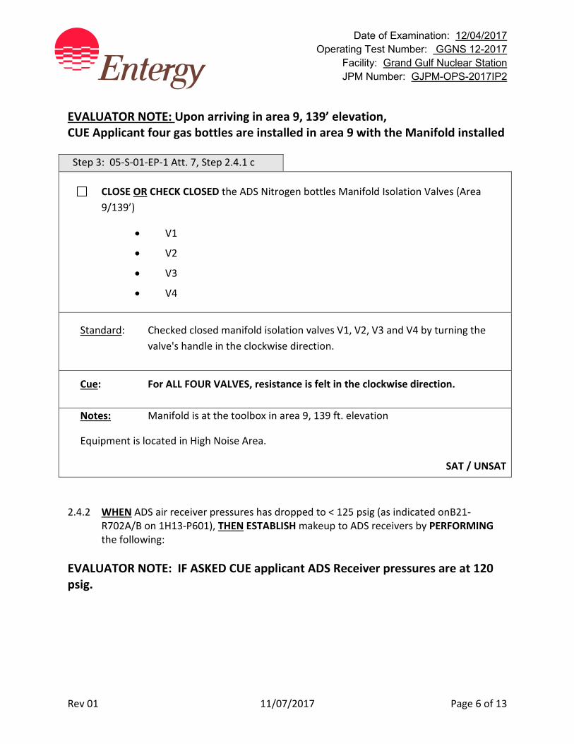
Date of Examination: 12/04/2017 Operating Test Number: GGNS 12-2017
Facility: Grand Gulf Nuclear Station JPM Number: GJPM-OPS-2017IP2
Rev 01 11/07/2017 Page 6 of 13
EVALUATOR NOTE: Upon arriving in area 9, 139’ elevation, CUE Applicant four gas bottles are installed in area 9 with the Manifold installed Step 3: 05-S-01-EP-1 Att. 7, Step 2.4.1 c
CLOSE OR CHECK CLOSED the ADS Nitrogen bottles Manifold Isolation Valves (Area 9/139’)
• V1
• V2
• V3
• V4
Standard: Checked closed manifold isolation valves V1, V2, V3 and V4 by turning the valve's handle in the clockwise direction.
Cue: For ALL FOUR VALVES, resistance is felt in the clockwise direction.
Notes: Manifold is at the toolbox in area 9, 139 ft. elevation
Equipment is located in High Noise Area.
SAT / UNSAT
2.4.2 WHEN ADS air receiver pressures has dropped to < 125 psig (as indicated onB21-
R702A/B on 1H13-P601), THEN ESTABLISH makeup to ADS receivers by PERFORMING the following:
EVALUATOR NOTE: IF ASKED CUE applicant ADS Receiver pressures are at 120 psig.
Date of Examination: 12/04/2017 Operating Test Number: GGNS 12-2017
Facility: Grand Gulf Nuclear Station JPM Number: GJPM-OPS-2017IP2
Rev 01 11/07/2017 Page 7 of 13
Step 4: 05-S-01-EP-1 Att. 7, Step 2.4.2 a
* OPEN (1) gas cylinder valve AND ADJUST gas cylinder regulator for that Nitrogen bottle to approximately 125 psig output pressure.
Standard: Rotated gas cylinder outlet valve in the counter-clockwise direction until resistance if felt.
Adjusted gas cylinder regulator by rotating the regulator pressure adjustment valve in the clockwise direction until pressure is approximately 125 psig.
Cue: Resistance is felt in the counter-clockwise direction on gas cylinder valve.
Use pen or finger to indicate Gas cylinder regulator is indicating 126 psig.
Notes: Area 9, 139’ elevation
SAT / UNSAT
Date of Examination: 12/04/2017 Operating Test Number: GGNS 12-2017
Facility: Grand Gulf Nuclear Station JPM Number: GJPM-OPS-2017IP2
Rev 01 11/07/2017 Page 8 of 13
Step 5: 05-S-01-EP-1 Att. 7, Step 2.4.2 b
* OPEN (1) ADS Nitrogen bottle Manifold Isolation Valve for the in-service Nitrogen bottle. Only OPEN (1) Manifold valve. (Area 9/139’)
• V1
• V2
• V3
• V4
Standard: Opened manifold isolation valve V1, V2, V3 or V4 by turning the valve's handle in the counter-clockwise direction.
Cue: For manifold isolation valve V1, V2, V3 or V4, resistance is felt in the counter-clockwise direction.
Notes: Area 9, 139’ elevation
SAT / UNSAT Step 6: 05-S-01-EP-1 Att. 7, Step 2.4.2 c
* OPEN P53-FA01. (Area 9/139’)
Standard: Opened valve 1P53-FA01, ADS Makeup Isolation by turning the valve's hand wheel in the counter-clockwise direction.
Cue: For valve 1P53-FA01, resistance is felt in the counter-clockwise direction.
Notes: Area 9, 139 ft. elevation
SAT / UNSAT
Date of Examination: 12/04/2017 Operating Test Number: GGNS 12-2017
Facility: Grand Gulf Nuclear Station JPM Number: GJPM-OPS-2017IP2
Rev 01 11/07/2017 Page 9 of 13
Step 7: 05-S-01-EP-1 Att. 7, Step 2.4.2 d
UNLOCK AND OPEN P53-FX004 to valve in the local pressure gauge.
Standard: Removed the tie-wrap from valve 1P53-FX004, Isolation for PI-R028 and opened the valve by turning its hand wheel in the counter-clockwise direction.
Cue: For valve 1P53-FX004, tie wrap is removed and resistance is felt in the counter-clockwise direction.
Notes: Area 9, 166 ft. elevation near 1P53-F003
Valve is located in High Radiation Area but is visible from outside the boundary.
SAT / UNSAT Applicant reviews CAUTION.
CAUTION
Allowing ADS Receiver pressure to exceed 165 psig May cause relief valves on ADS receivers to lift.
Date of Examination: 12/04/2017 Operating Test Number: GGNS 12-2017
Facility: Grand Gulf Nuclear Station JPM Number: GJPM-OPS-2017IP2
Rev 01 11/07/2017 Page 10 of 13
Step 8: 05-S-01-EP-1 Att. 7, Step 2.4.2 e
* UNLOCK AND Slowly OPEN 1P53F043 (Area 9, El. 166), OBSERVING pressure on P53-R028.
Standard: Removed the tie-wrap from valve 1P53-F043, ADS Makeup Isolation and opened the valve by turning its hand wheel in the counter-clockwise direction, while monitoring pressure on 1P53-PI-R028.
Cue:
• For valve 1P53-F043, resistance is felt in the counter-clockwise direction.
• Pressure on 1P53-PI-R028 is 126 psig.
Notes: Area 9, 166’ elevation
Valve is located in High Radiation Area but is visible from outside the boundary.
Observation of pressure is not critical.
SAT / UNSAT
EVALUATOR TERMINATE JPM
Date of Examination: 12/04/2017 Operating Test Number: GGNS 12-2017
Facility: Grand Gulf Nuclear Station JPM Number: GJPM-OPS-2017IP2
Rev 01 11/07/2017 Page 11 of 13
Task Standard(s):
• OPENED (1) gas cylinder valve • ADJUSTED gas cylinder regulator for that Nitrogen bottle to approximately 125 psig
output pressure • OPENED (1) ADS Nitrogen bottle Manifold Isolation Valve for the in-service Nitrogen
bottle • OPENED P53-FA01, ADS Makeup Isolation • OPENED 1P53F043, ADS Makeup Isolation Nitrogen is being supplied to ADS valve actuators per 05-S-01-EP-1 Attachment 7, Defeating Containment and Drywell Instrument Air Isolation Interlocks.
SAT / UNSAT Remember to record stop time
Date of Examination: 12/04/2017 Operating Test Number: GGNS 12-2017
Facility: Grand Gulf Nuclear Station JPM Number: GJPM-OPS-2017IP2
Rev 01 11/07/2017 Page 12 of 13
Follow-Up Questions & Answers:
Comments:
GJPM-OPS-2017IP2
Give this page to the applicant
Initial Condition(s): • Emergency Procedures have been entered
• Following valves are open
o P53-F001, INST AIR SPLY HDR TO CTMT
o P53-F007, INST AIR SPLY HDR TO DRWL
o P53-F026A, INST AIR SPLY HDR TO AUX BLDG
o P53-F026B, INST AIR SPLY HDR TO AUX BLDG
• Four nitrogen bottles are installed at the connection downstream of P53-FA01, with the regulators attached
• B21-R702A and B, ADS A and B AIR RCVR PRESS indicate < 125 psig
Initiating Cue(s):
• Control Room Supervisor directs you to perform steps 2.4.1 and 2.4.2 of 05-S-01-EP-1, Attachment 7 Defeating Containment and Drywell Instrument Air Isolation Interlocks
Date of Examination: 12/04/2017 Operating Test Number: GGNS 12-2017
Facility: Grand Gulf Nuclear Station JPM Number: GJPM-OPS-2017IPB2
Rev. 01 11/28/2017 Page 1 of 12
2017I PB2
GGNS
2017 NRC Operating Test
Job Performance Measure
JPM Number: GJPM-OPS-2017IPB2 JPM Title: Return Fire Water Pumps to Stby Facility Number: __GJPM-OPS-P6404 rev 2 (If Bank or Modified from Bank)
JPM Attributes:
New Modified Direct from bank
Time Critical Alternate Path Validation Time: 15 min
Prepared By: Michael Rasch 11/28/2017 Exam Developer Date
Ops Review: Robert Brinkman 11/28/2017 1st Validation by Ops Rep or Ops Validation Crew Date
Validated By: Robert Chamblee 11/28/2017 2nd Validation by Ops Validation Crew Date
Approved By: Ricky Liddell 11/28/2017 Project Lead or Exam Team Lead Date
Date of Examination: 12/04/2017 Operating Test Number: GGNS 12-2017
Facility: Grand Gulf Nuclear Station JPM Number: GJPM-OPS-2017IPB2
Rev. 01 11/28/2017 Page 2 of 12
Return Fire Water Pumps to Stby
Time Critical Alternate Path Validation Time: 15 Min
Setting: Plant Type: NLO\RO\SRO Task: NOB‐P64‐NORMAL‐3 K&A: 286000 A4.05 (3.3/3.3) Generic 2.1.30 (4.4/4.0) Safety Function: 8 – Plant Service Systems PRA Applicability: No 10CFR 55.45(a) (4); (5); (12) Performance: Simulate Reference(s): 04‐S‐01‐P64‐1 Rev. 64, Fire Protection Water System Handout(s): 04‐S‐01‐P64‐1 Precautions & Limitations and section 4.4 # Manipulations: 6 # Critical Steps: 6 Low Power: No
Emergency/Abnormal: No
RCA entry: No
Engineered Safety Function: No
Simulator Setup/Required Plant Conditions:
Fire Water Pump House is accessible Safety Concerns:
Wear appropriate personal protective equipment.
No climbing. Point up or down while you explain what you are going to do.
Date of Examination: 12/04/2017 Operating Test Number: GGNS 12-2017
Facility: Grand Gulf Nuclear Station JPM Number: GJPM-OPS-2017IPB2
Rev. 01 11/28/2017 Page 3 of 12
Name: ___________________________ Time Start: _______ Time Stop: _______
Initial Condition(s):
Fire was reported at ESF Transformer 12 and Fire Deluge was initiated
Motor Driven Fire Pump was manually started in the Control Room
Diesel Driven Fire Pump A automatically started
Fire is out and deluge has been isolated
Fire pumps have been running for 35 minutes
Initiating Cue(s):
Control Room Supervisor directs you to place running Fire Water Pumps in Standby per section 4.4 of SOI 04‐S‐01‐P64‐1
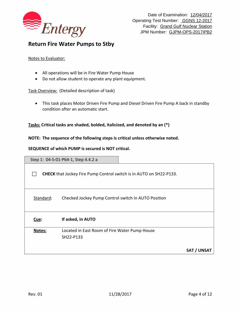
Date of Examination: 12/04/2017 Operating Test Number: GGNS 12-2017
Facility: Grand Gulf Nuclear Station JPM Number: GJPM-OPS-2017IPB2
Rev. 01 11/28/2017 Page 4 of 12
Return Fire Water Pumps to Stby
Notes to Evaluator:
All operations will be in Fire Water Pump House
Do not allow student to operate any plant equipment.
Task Overview: (Detailed description of task)
This task places Motor Driven Fire Pump and Diesel Driven Fire Pump A back in standby condition after an automatic start.
Tasks: Critical tasks are shaded, bolded, italicized, and denoted by an (*)
NOTE: The sequence of the following steps is critical unless otherwise noted.
SEQUENCE of which PUMP is secured is NOT critical.
Step 1: 04‐S‐01‐P64‐1, Step 4.4.2 a
CHECK that Jockey Fire Pump Control switch is in AUTO on SH22‐P133.
Standard: Checked Jockey Pump Control switch in AUTO Position
Cue: If asked, in AUTO
Notes: Located in East Room of Fire Water Pump House
SH22‐P133
SAT / UNSAT
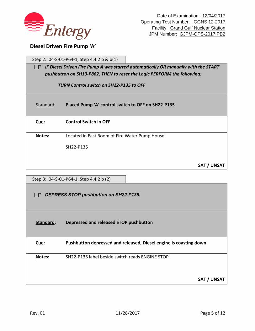
Date of Examination: 12/04/2017 Operating Test Number: GGNS 12-2017
Facility: Grand Gulf Nuclear Station JPM Number: GJPM-OPS-2017IPB2
Rev. 01 11/28/2017 Page 5 of 12
Diesel Driven Fire Pump ‘A’
Step 2: 04‐S‐01‐P64‐1, Step 4.4.2 b & b(1)
* IF Diesel Driven Fire Pump A was started automatically OR manually with the START
pushbutton on SH13‐P862, THEN to reset the Logic PERFORM the following:
TURN Control switch on SH22‐P135 to OFF
Standard: Placed Pump ‘A’ control switch to OFF on SH22‐P135
Cue: Control Switch in OFF
Notes: Located in East Room of Fire Water Pump House
SH22‐P135
SAT / UNSAT
Step 3: 04‐S‐01‐P64‐1, Step 4.4.2 b (2)
* DEPRESS STOP pushbutton on SH22-P135.
Standard: Depressed and released STOP pushbutton
Cue: Pushbutton depressed and released, Diesel engine is coasting down
Notes: SH22‐P135 label beside switch reads ENGINE STOP
SAT / UNSAT
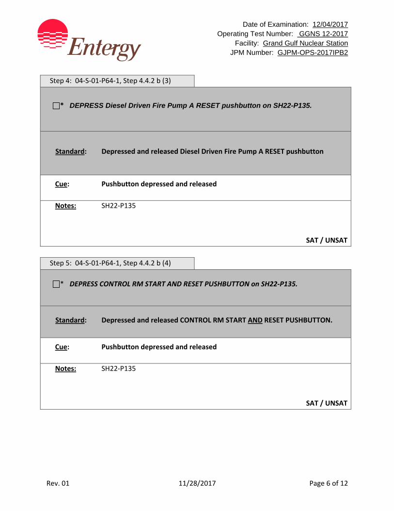
Date of Examination: 12/04/2017 Operating Test Number: GGNS 12-2017
Facility: Grand Gulf Nuclear Station JPM Number: GJPM-OPS-2017IPB2
Rev. 01 11/28/2017 Page 6 of 12
Step 4: 04‐S‐01‐P64‐1, Step 4.4.2 b (3)
* DEPRESS Diesel Driven Fire Pump A RESET pushbutton on SH22-P135.
Standard: Depressed and released Diesel Driven Fire Pump A RESET pushbutton
Cue: Pushbutton depressed and released
Notes: SH22‐P135
SAT / UNSAT
Step 5: 04‐S‐01‐P64‐1, Step 4.4.2 b (4)
* DEPRESS CONTROL RM START AND RESET PUSHBUTTON on SH22‐P135.
Standard: Depressed and released CONTROL RM START AND RESET PUSHBUTTON.
Cue: Pushbutton depressed and released
Notes: SH22‐P135
SAT / UNSAT
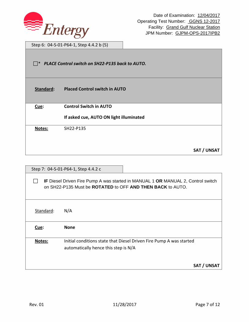
Date of Examination: 12/04/2017 Operating Test Number: GGNS 12-2017
Facility: Grand Gulf Nuclear Station JPM Number: GJPM-OPS-2017IPB2
Rev. 01 11/28/2017 Page 7 of 12
Step 6: 04‐S‐01‐P64‐1, Step 4.4.2 b (5)
* PLACE Control switch on SH22‐P135 back to AUTO.
Standard: Placed Control switch in AUTO
Cue: Control Switch in AUTO
If asked cue, AUTO ON light illuminated
Notes: SH22‐P135
SAT / UNSAT
Step 7: 04‐S‐01‐P64‐1, Step 4.4.2 c
IF Diesel Driven Fire Pump A was started in MANUAL 1 OR MANUAL 2, Control switch on SH22-P135 Must be ROTATED to OFF AND THEN BACK to AUTO.
Standard: N/A
Cue: None
Notes: Initial conditions state that Diesel Driven Fire Pump A was started
automatically hence this step is N/A
SAT / UNSAT
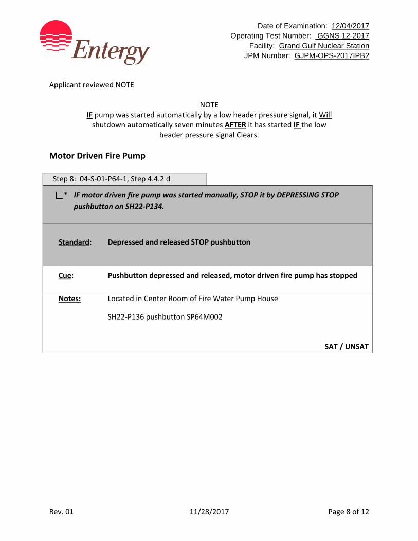
Date of Examination: 12/04/2017 Operating Test Number: GGNS 12-2017
Facility: Grand Gulf Nuclear Station JPM Number: GJPM-OPS-2017IPB2
Rev. 01 11/28/2017 Page 8 of 12
Applicant reviewed NOTE
NOTE IF pump was started automatically by a low header pressure signal, it Will shutdown automatically seven minutes AFTER it has started IF the low
header pressure signal Clears.
Motor Driven Fire Pump Step 8: 04‐S‐01‐P64‐1, Step 4.4.2 d
* IF motor driven fire pump was started manually, STOP it by DEPRESSING STOP
pushbutton on SH22‐P134.
Standard: Depressed and released STOP pushbutton
Cue: Pushbutton depressed and released, motor driven fire pump has stopped
Notes: Located in Center Room of Fire Water Pump House
SH22‐P136 pushbutton SP64M002
SAT / UNSAT
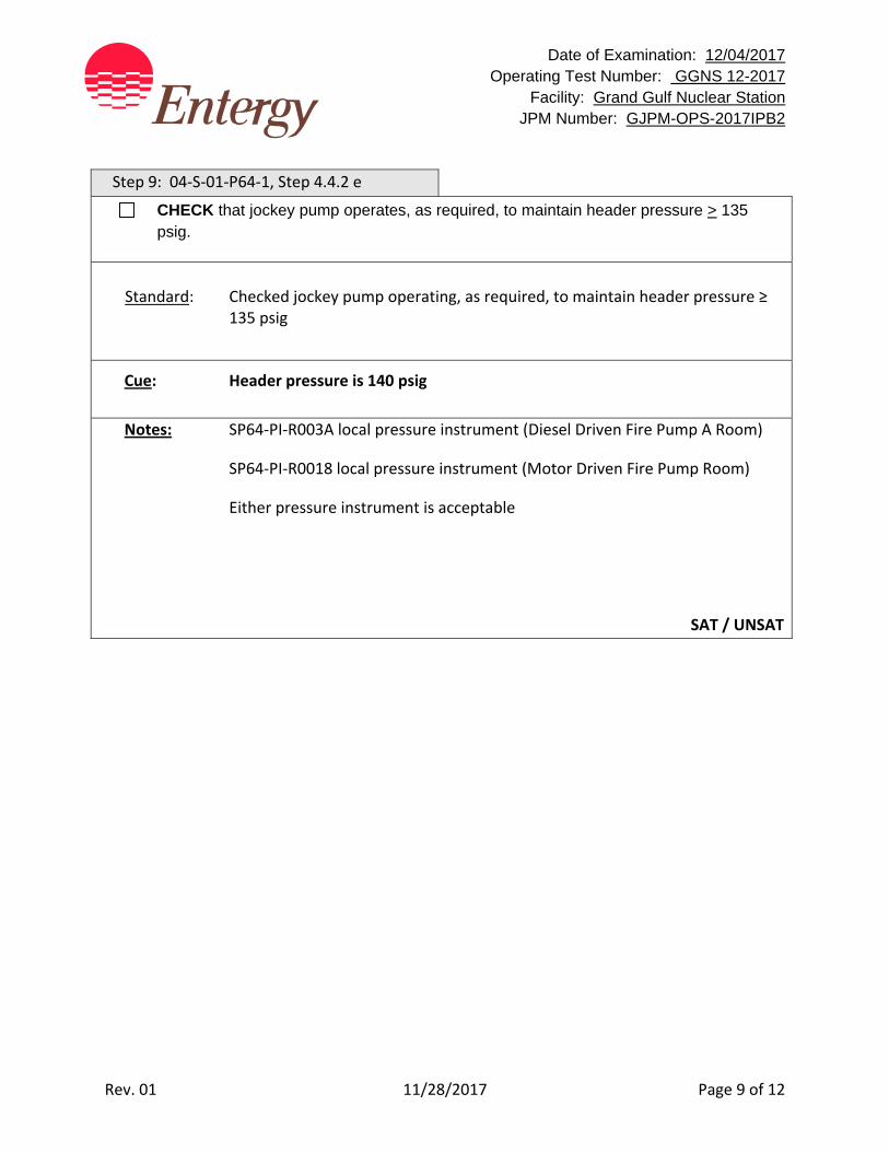
Date of Examination: 12/04/2017 Operating Test Number: GGNS 12-2017
Facility: Grand Gulf Nuclear Station JPM Number: GJPM-OPS-2017IPB2
Rev. 01 11/28/2017 Page 9 of 12
Step 9: 04‐S‐01‐P64‐1, Step 4.4.2 e
CHECK that jockey pump operates, as required, to maintain header pressure > 135 psig.
Standard: Checked jockey pump operating, as required, to maintain header pressure ≥ 135 psig
Cue: Header pressure is 140 psig
Notes: SP64‐PI‐R003A local pressure instrument (Diesel Driven Fire Pump A Room)
SP64‐PI‐R0018 local pressure instrument (Motor Driven Fire Pump Room)
Either pressure instrument is acceptable
SAT / UNSAT

Date of Examination: 12/04/2017 Operating Test Number: GGNS 12-2017
Facility: Grand Gulf Nuclear Station JPM Number: GJPM-OPS-2017IPB2
Rev. 01 11/28/2017 Page 10 of 12
Task Standard(s):
For Diesel Driven Fire Pump A on SH22‐P135
Placed control switch to OFF
Depressed and released STOP pushbutton
Depressed and released Diesel Driven Fire Pump A RESET pushbutton
Depressed and released CONTROL RM START AND RESET pushbutton
Placed Control switch in AUTO For Motor Driven Fire Pump on SH22‐P134
Depressed and released STOP pushbutton
SAT / UNSAT
Remember to record stop time
Date of Examination: 12/04/2017 Operating Test Number: GGNS 12-2017
Facility: Grand Gulf Nuclear Station JPM Number: GJPM-OPS-2017IPB2
Rev. 01 11/28/2017 Page 11 of 12
Follow‐Up Questions & Answers:
Comments:
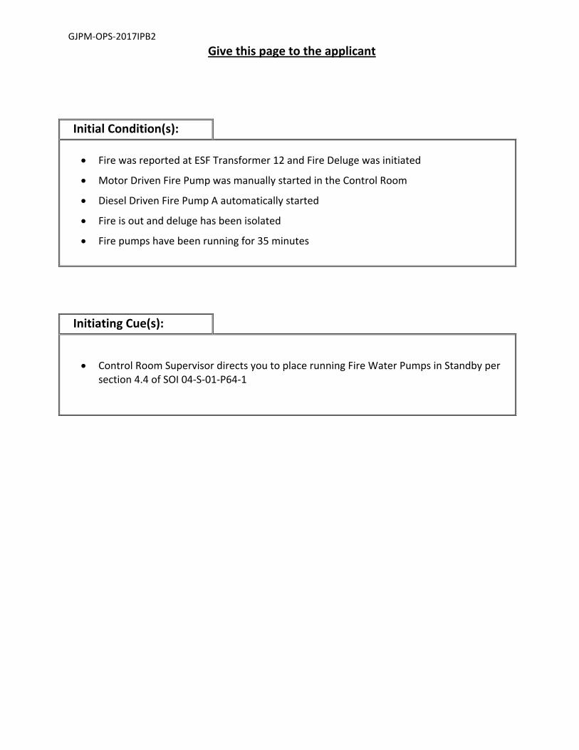
GJPM‐OPS‐2017IPB2
Give this page to the applicant
Initial Condition(s):
Fire was reported at ESF Transformer 12 and Fire Deluge was initiated
Motor Driven Fire Pump was manually started in the Control Room
Diesel Driven Fire Pump A automatically started
Fire is out and deluge has been isolated
Fire pumps have been running for 35 minutes
Initiating Cue(s):
Control Room Supervisor directs you to place running Fire Water Pumps in Standby per section 4.4 of SOI 04‐S‐01‐P64‐1
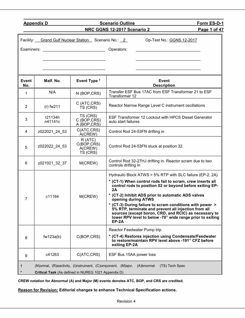
Appendix D Scenario Outline Form ES-D-1 NRC GGNS 12-2017 Scenario 2 Page 1 of 47
Revision 4
Facility: Grand Gulf Nuclear Station Scenario No.: 2 Op-Test No.: GGNS 12-2017 Examiners: ____________________________ Operators: _____________________________
____________________________ _____________________________ ____________________________ _____________________________
Event No.
Malf. No. Event Type † Event Description
1 N/A N (BOP,CRS) Transfer ESF Bus 17AC from ESF Transformer 21 to ESF Transformer 12
2 (r) fw211 C (ATC,CRS)
TS (CRS) Reactor Narrow Range Level C instrument oscillations
3 r21134h n41141c
TS (CRS) C (BOP,CRS) A (BOP,CRS)
ESF Transformer 12 Lockout with HPCS Diesel Generator auto start failures
4 z022021_24_53 C(ATC,CRS) A(CREW)
Control Rod 24-53FN drifting in
5 z022022_24_53 R (ATC)
C(BOP,CRS) A(CREW) TS (CRS)
Control Rod 24-53FN stuck at position 32.
6 z021021_32_37 M(CREW) Control Rod 32-27HJ drifting in. Reactor scram due to two controls drifting in
7 c11164 M(CREW)
Hydraulic Block ATWS > 5% RTP with SLC failure (EP-2, 2A) * (CT-1) When control rods fail to scram, crew inserts all
control rods to position 02 or beyond before exiting EP-2A
* (CT-2) Inhibit ADS prior to automatic ADS valves opening during ATWS
* (CT-3) During failure to scram conditions with power > 5% RTP, terminate and prevent all injection from all sources (except boron, CRD, and RCIC) as necessary to lower RPV level to below -70” wide range prior to exiting EP-2A
8 fw123a(b) C(BOP,CRS)
Reactor Feedwater Pump trip. * (CT-4) Restores injection using Condensate/Feedwater
to restore/maintain RPV level above -191” CFZ before exiting EP-2A
9 c41263 C(ATC,CRS) ESF Bus 15AA power loss
† (N)ormal, (R)eactivity, (I)nstrument, (C)omponent, (M)ajor, (A)bnormal (TS) Tech Spec
* Critical Task (As defined in NUREG 1021 Appendix D) CREW notation for Abnormal (A) and Major (M) events denotes ATC, BOP, and CRS are credited.
Reason for Revision: Editorial changes to enhance Technical Specification actions.
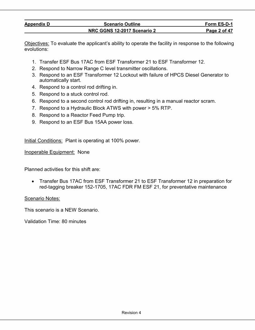
Appendix D Scenario Outline Form ES-D-1 NRC GGNS 12-2017 Scenario 2 Page 2 of 47
Revision 4
Objectives: To evaluate the applicant’s ability to operate the facility in response to the following evolutions:
1. Transfer ESF Bus 17AC from ESF Transformer 21 to ESF Transformer 12. 2. Respond to Narrow Range C level transmitter oscillations. 3. Respond to an ESF Transformer 12 Lockout with failure of HPCS Diesel Generator to
automatically start. 4. Respond to a control rod drifting in. 5. Respond to a stuck control rod. 6. Respond to a second control rod drifting in, resulting in a manual reactor scram. 7. Respond to a Hydraulic Block ATWS with power > 5% RTP. 8. Respond to a Reactor Feed Pump trip. 9. Respond to an ESF Bus 15AA power loss.
Initial Conditions: Plant is operating at 100% power. Inoperable Equipment: None Planned activities for this shift are:
• Transfer Bus 17AC from ESF Transformer 21 to ESF Transformer 12 in preparation for red-tagging breaker 152-1705, 17AC FDR FM ESF 21, for preventative maintenance
Scenario Notes: This scenario is a NEW Scenario. Validation Time: 80 minutes
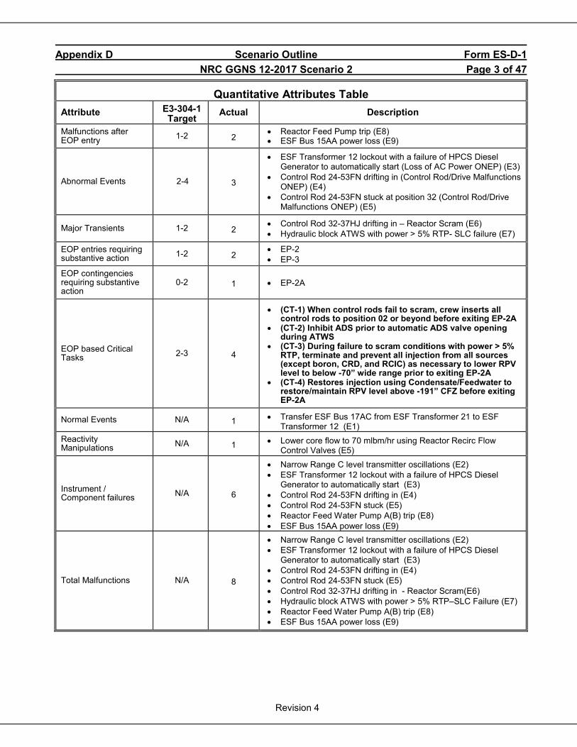
Appendix D Scenario Outline Form ES-D-1 NRC GGNS 12-2017 Scenario 2 Page 3 of 47
Revision 4
Quantitative Attributes Table Attribute E3-304-1
Target Actual Description
Malfunctions after EOP entry 1-2 2
• Reactor Feed Pump trip (E8) • ESF Bus 15AA power loss (E9)
Abnormal Events 2-4 3
• ESF Transformer 12 lockout with a failure of HPCS Diesel Generator to automatically start (Loss of AC Power ONEP) (E3)
• Control Rod 24-53FN drifting in (Control Rod/Drive Malfunctions ONEP) (E4)
• Control Rod 24-53FN stuck at position 32 (Control Rod/Drive Malfunctions ONEP) (E5)
Major Transients 1-2 2 • Control Rod 32-37HJ drifting in – Reactor Scram (E6) • Hydraulic block ATWS with power > 5% RTP- SLC failure (E7)
EOP entries requiring substantive action 1-2 2
• EP-2 • EP-3
EOP contingencies requiring substantive action
0-2 1 • EP-2A
EOP based Critical Tasks 2-3 4
• (CT-1) When control rods fail to scram, crew inserts all control rods to position 02 or beyond before exiting EP-2A
• (CT-2) Inhibit ADS prior to automatic ADS valve opening during ATWS
• (CT-3) During failure to scram conditions with power > 5% RTP, terminate and prevent all injection from all sources (except boron, CRD, and RCIC) as necessary to lower RPV level to below -70” wide range prior to exiting EP-2A
• (CT-4) Restores injection using Condensate/Feedwater to restore/maintain RPV level above -191” CFZ before exiting EP-2A
Normal Events N/A 1 • Transfer ESF Bus 17AC from ESF Transformer 21 to ESF Transformer 12 (E1)
Reactivity Manipulations N/A 1 • Lower core flow to 70 mlbm/hr using Reactor Recirc Flow
Control Valves (E5)
Instrument / Component failures N/A 6
• Narrow Range C level transmitter oscillations (E2) • ESF Transformer 12 lockout with a failure of HPCS Diesel
Generator to automatically start (E3) • Control Rod 24-53FN drifting in (E4) • Control Rod 24-53FN stuck (E5) • Reactor Feed Water Pump A(B) trip (E8) • ESF Bus 15AA power loss (E9)
Total Malfunctions N/A 8
• Narrow Range C level transmitter oscillations (E2) • ESF Transformer 12 lockout with a failure of HPCS Diesel
Generator to automatically start (E3) • Control Rod 24-53FN drifting in (E4) • Control Rod 24-53FN stuck (E5) • Control Rod 32-37HJ drifting in - Reactor Scram(E6) • Hydraulic block ATWS with power > 5% RTP–SLC Failure (E7) • Reactor Feed Water Pump A(B) trip (E8) • ESF Bus 15AA power loss (E9)
Appendix D Scenario Outline Form ES-D-1 NRC GGNS 12-2017 Scenario 2 Page 4 of 47
Revision 4
Top 10 systems and operator actions important to risk that are tested:
RPS (Event 6)
ESF Power (Event 3)
Condensate (Event 8)
Failure to align alternate power to 4.16 KV or 6.9 KV buses (Event 3)
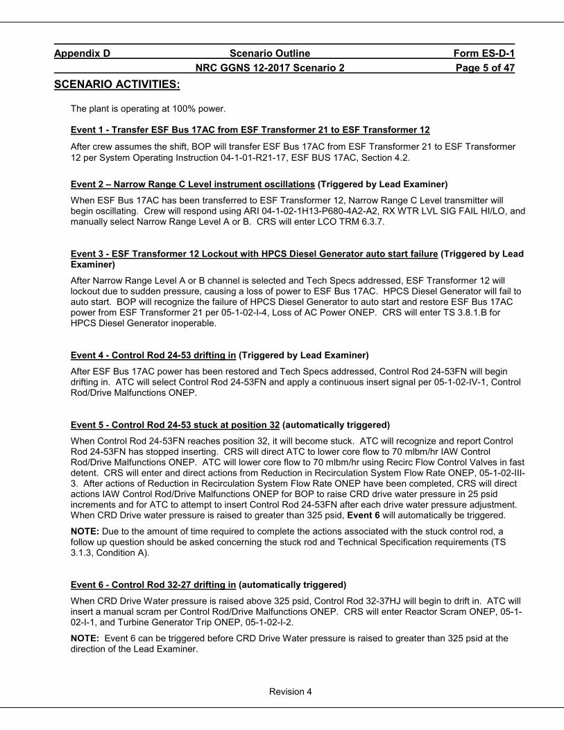
Appendix D Scenario Outline Form ES-D-1 NRC GGNS 12-2017 Scenario 2 Page 5 of 47
Revision 4
SCENARIO ACTIVITIES:
The plant is operating at 100% power. Event 1 - Transfer ESF Bus 17AC from ESF Transformer 21 to ESF Transformer 12
After crew assumes the shift, BOP will transfer ESF Bus 17AC from ESF Transformer 21 to ESF Transformer 12 per System Operating Instruction 04-1-01-R21-17, ESF BUS 17AC, Section 4.2.
Event 2 – Narrow Range C Level instrument oscillations (Triggered by Lead Examiner)
When ESF Bus 17AC has been transferred to ESF Transformer 12, Narrow Range C Level transmitter will begin oscillating. Crew will respond using ARI 04-1-02-1H13-P680-4A2-A2, RX WTR LVL SIG FAIL HI/LO, and manually select Narrow Range Level A or B. CRS will enter LCO TRM 6.3.7.
Event 3 - ESF Transformer 12 Lockout with HPCS Diesel Generator auto start failure (Triggered by Lead Examiner)
After Narrow Range Level A or B channel is selected and Tech Specs addressed, ESF Transformer 12 will lockout due to sudden pressure, causing a loss of power to ESF Bus 17AC. HPCS Diesel Generator will fail to auto start. BOP will recognize the failure of HPCS Diesel Generator to auto start and restore ESF Bus 17AC power from ESF Transformer 21 per 05-1-02-I-4, Loss of AC Power ONEP. CRS will enter TS 3.8.1.B for HPCS Diesel Generator inoperable.
Event 4 - Control Rod 24-53 drifting in (Triggered by Lead Examiner)
After ESF Bus 17AC power has been restored and Tech Specs addressed, Control Rod 24-53FN will begin drifting in. ATC will select Control Rod 24-53FN and apply a continuous insert signal per 05-1-02-IV-1, Control Rod/Drive Malfunctions ONEP.
Event 5 - Control Rod 24-53 stuck at position 32 (automatically triggered)
When Control Rod 24-53FN reaches position 32, it will become stuck. ATC will recognize and report Control Rod 24-53FN has stopped inserting. CRS will direct ATC to lower core flow to 70 mlbm/hr IAW Control Rod/Drive Malfunctions ONEP. ATC will lower core flow to 70 mlbm/hr using Recirc Flow Control Valves in fast detent. CRS will enter and direct actions from Reduction in Recirculation System Flow Rate ONEP, 05-1-02-III-3. After actions of Reduction in Recirculation System Flow Rate ONEP have been completed, CRS will direct actions IAW Control Rod/Drive Malfunctions ONEP for BOP to raise CRD drive water pressure in 25 psid increments and for ATC to attempt to insert Control Rod 24-53FN after each drive water pressure adjustment. When CRD Drive water pressure is raised to greater than 325 psid, Event 6 will automatically be triggered.
NOTE: Due to the amount of time required to complete the actions associated with the stuck control rod, a follow up question should be asked concerning the stuck rod and Technical Specification requirements (TS 3.1.3, Condition A).
Event 6 - Control Rod 32-27 drifting in (automatically triggered)
When CRD Drive Water pressure is raised above 325 psid, Control Rod 32-37HJ will begin to drift in. ATC will insert a manual scram per Control Rod/Drive Malfunctions ONEP. CRS will enter Reactor Scram ONEP, 05-1-02-I-1, and Turbine Generator Trip ONEP, 05-1-02-I-2.
NOTE: Event 6 can be triggered before CRD Drive Water pressure is raised to greater than 325 psid at the direction of the Lead Examiner.
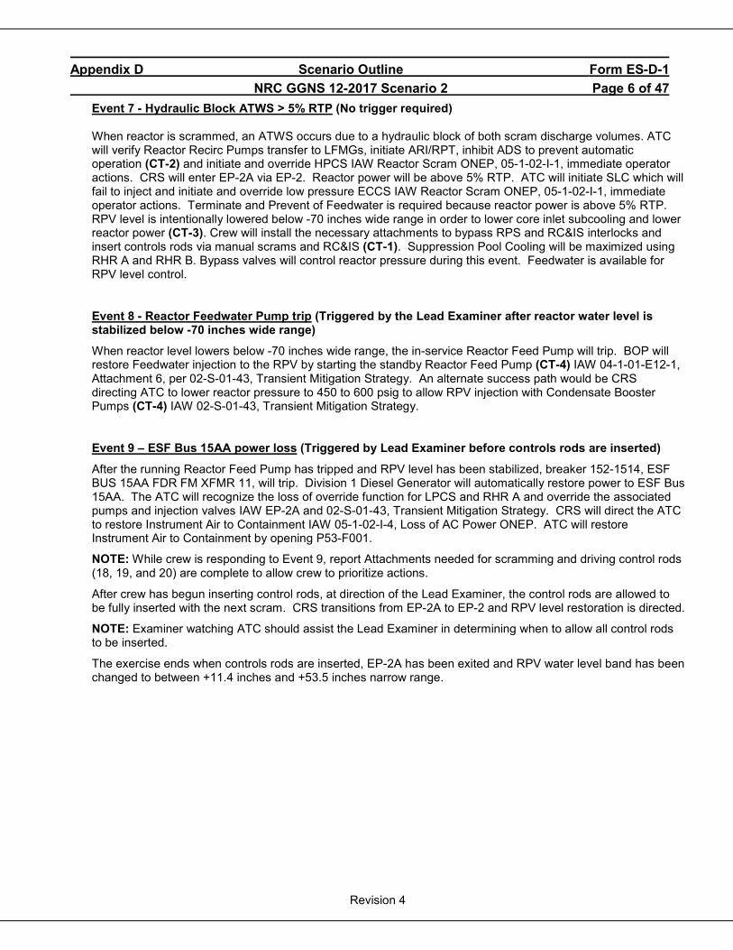
Appendix D Scenario Outline Form ES-D-1 NRC GGNS 12-2017 Scenario 2 Page 6 of 47
Revision 4
Event 7 - Hydraulic Block ATWS > 5% RTP (No trigger required)
When reactor is scrammed, an ATWS occurs due to a hydraulic block of both scram discharge volumes. ATC will verify Reactor Recirc Pumps transfer to LFMGs, initiate ARI/RPT, inhibit ADS to prevent automatic operation (CT-2) and initiate and override HPCS IAW Reactor Scram ONEP, 05-1-02-I-1, immediate operator actions. CRS will enter EP-2A via EP-2. Reactor power will be above 5% RTP. ATC will initiate SLC which will fail to inject and initiate and override low pressure ECCS IAW Reactor Scram ONEP, 05-1-02-I-1, immediate operator actions. Terminate and Prevent of Feedwater is required because reactor power is above 5% RTP. RPV level is intentionally lowered below -70 inches wide range in order to lower core inlet subcooling and lower reactor power (CT-3). Crew will install the necessary attachments to bypass RPS and RC&IS interlocks and insert controls rods via manual scrams and RC&IS (CT-1). Suppression Pool Cooling will be maximized using RHR A and RHR B. Bypass valves will control reactor pressure during this event. Feedwater is available for RPV level control.
Event 8 - Reactor Feedwater Pump trip (Triggered by the Lead Examiner after reactor water level is stabilized below -70 inches wide range)
When reactor level lowers below -70 inches wide range, the in-service Reactor Feed Pump will trip. BOP will restore Feedwater injection to the RPV by starting the standby Reactor Feed Pump (CT-4) IAW 04-1-01-E12-1, Attachment 6, per 02-S-01-43, Transient Mitigation Strategy. An alternate success path would be CRS directing ATC to lower reactor pressure to 450 to 600 psig to allow RPV injection with Condensate Booster Pumps (CT-4) IAW 02-S-01-43, Transient Mitigation Strategy.
Event 9 – ESF Bus 15AA power loss (Triggered by Lead Examiner before controls rods are inserted)
After the running Reactor Feed Pump has tripped and RPV level has been stabilized, breaker 152-1514, ESF BUS 15AA FDR FM XFMR 11, will trip. Division 1 Diesel Generator will automatically restore power to ESF Bus 15AA. The ATC will recognize the loss of override function for LPCS and RHR A and override the associated pumps and injection valves IAW EP-2A and 02-S-01-43, Transient Mitigation Strategy. CRS will direct the ATC to restore Instrument Air to Containment IAW 05-1-02-I-4, Loss of AC Power ONEP. ATC will restore Instrument Air to Containment by opening P53-F001.
NOTE: While crew is responding to Event 9, report Attachments needed for scramming and driving control rods (18, 19, and 20) are complete to allow crew to prioritize actions.
After crew has begun inserting control rods, at direction of the Lead Examiner, the control rods are allowed to be fully inserted with the next scram. CRS transitions from EP-2A to EP-2 and RPV level restoration is directed.
NOTE: Examiner watching ATC should assist the Lead Examiner in determining when to allow all control rods to be inserted.
The exercise ends when controls rods are inserted, EP-2A has been exited and RPV water level band has been changed to between +11.4 inches and +53.5 inches narrow range.
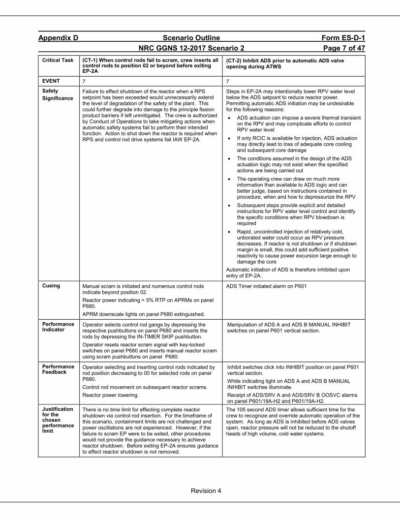
Appendix D Scenario Outline Form ES-D-1 NRC GGNS 12-2017 Scenario 2 Page 7 of 47
Revision 4
Critical Task (CT-1) When control rods fail to scram, crew inserts all control rods to position 02 or beyond before exiting EP-2A
(CT-2) Inhibit ADS prior to automatic ADS valve opening during ATWS
EVENT 7 7
Safety Significance
Failure to effect shutdown of the reactor when a RPS setpoint has been exceeded would unnecessarily extend the level of degradation of the safety of the plant. This could further degrade into damage to the principle fission product barriers if left unmitigated. The crew is authorized by Conduct of Operations to take mitigating actions when automatic safety systems fail to perform their intended function. Action to shut down the reactor is required when RPS and control rod drive systems fail IAW EP-2A.
Steps in EP-2A may intentionally lower RPV water level below the ADS setpoint to reduce reactor power. Permitting automatic ADS initiation may be undesirable for the following reasons: • ADS actuation can impose a severe thermal transient
on the RPV and may complicate efforts to control RPV water level
• If only RCIC is available for injection, ADS actuation may directly lead to loss of adequate core cooling and subsequent core damage
• The conditions assumed in the design of the ADS actuation logic may not exist when the specified actions are being carried out
• The operating crew can draw on much more information than available to ADS logic and can better judge, based on instructions contained in procedure, when and how to depressurize the RPV
• Subsequent steps provide explicit and detailed instructions for RPV water level control and identify the specific conditions when RPV blowdown is required
• Rapid, uncontrolled injection of relatively cold, unborated water could occur as RPV pressure decreases. If reactor is not shutdown or if shutdown margin is small, this could add sufficient positive reactivity to cause power excursion large enough to damage the core
Automatic initiation of ADS is therefore inhibited upon entry of EP-2A.
Cueing Manual scram is initiated and numerous control rods indicate beyond position 02. Reactor power indicating > 5% RTP on APRMs on panel P680. APRM downscale lights on panel P680 extinguished.
ADS Timer initiated alarm on P601
Performance Indicator
Operator selects control rod gangs by depressing the respective pushbuttons on panel P680 and inserts the rods by depressing the IN-TIMER SKIP pushbutton. Operator resets reactor scram signal with key-locked switches on panel P680 and inserts manual reactor scram using scram pushbuttons on panel P680.
Manipulation of ADS A and ADS B MANUAL INHIBIT switches on panel P601 vertical section.
Performance Feedback
Operator selecting and inserting control rods indicated by rod position decreasing to 00 for selected rods on panel P680. Control rod movement on subsequent reactor scrams. Reactor power lowering.
Inhibit switches click into INHIBIT position on panel P601 vertical section. White indicating light on ADS A and ADS B MANUAL INHIBIT switches illuminate. Receipt of ADS/SRV A and ADS/SRV B OOSVC alarms on panel P601/18A-H2 and P601/19A-H2.
Justification for the chosen performance limit
There is no time limit for effecting complete reactor shutdown via control rod insertion. For the timeframe of this scenario, containment limits are not challenged and power oscillations are not experienced. However, if the failure to scram EP were to be exited, other procedures would not provide the guidance necessary to achieve reactor shutdown. Before exiting EP-2A ensures guidance to effect reactor shutdown is not removed.
The 105 second ADS timer allows sufficient time for the crew to recognize and override automatic operation of the system. As long as ADS is inhibited before ADS valves open, reactor pressure will not be reduced to the shutoff heads of high volume, cold water systems.
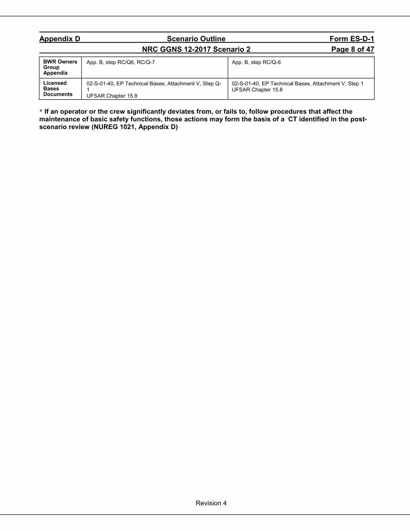
Appendix D Scenario Outline Form ES-D-1 NRC GGNS 12-2017 Scenario 2 Page 8 of 47
Revision 4
BWR Owners Group Appendix
App. B, step RC/Q6, RC/Q-7
App. B, step RC/Q-6
Licensed Bases Documents
02-S-01-40, EP Technical Bases, Attachment V, Step Q-1 UFSAR Chapter 15.8
02-S-01-40, EP Technical Bases, Attachment V, Step 1 UFSAR Chapter 15.8
* If an operator or the crew significantly deviates from, or fails to, follow procedures that affect the maintenance of basic safety functions, those actions may form the basis of a CT identified in the post-scenario review (NUREG 1021, Appendix D)
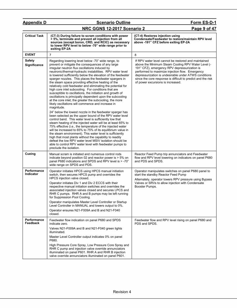
Appendix D Scenario Outline Form ES-D-1 NRC GGNS 12-2017 Scenario 2 Page 9 of 47
Revision 4
Critical Task (CT-3) During failure to scram conditions with power > 5%, terminate and prevent all injection from all sources (except boron, CRD, and RCIC) as necessary to lower RPV level to below -70” wide range prior to exiting EP-2A
(CT-4) Restores injection using Condensate/Feedwater to restore/maintain RPV level above -191” CFZ before exiting EP-2A
EVENT 7 8
Safety Significance
Regarding lowering level below -70” wide range, to prevent or mitigate the consequences of any large irregular neutron flux oscillations induced by neutronic/thermal-hydraulic instabilities. RPV water level is lowered sufficiently below the elevation of the feedwater sparger nozzles. This places the feedwater spargers in the steam space providing effective heating of the relatively cold feedwater and eliminating the potential for high core inlet subcooling. For conditions that are susceptible to oscillations, the initiation and growth of oscillations is principally dependent upon the subcooling at the core inlet; the greater the subcooling, the more likely oscillations will commence and increase in magnitude. 24” below the lowest nozzle in the feedwater sparger has been selected as the upper bound of the RPV water level control band. This water level is sufficiently low that steam heating of the injected water will be at least 65% to 75% effective (i.e., the temperature of the injected water will be increased to 65% to 75% of its equilibrium value in the steam environment). This water level is sufficiently high that most plants without the capability to readily defeat the low RPV water level MSIV isolation should be able to control RPV water level with feedwater pumps to preclude the isolation.
If RPV water level cannot be restored and maintained above the Minimum Steam Cooling RPV Water Level (-191” CFZ), emergency RPV depressurization is performed to maximize injection flow. Emergency depressurization is undesirable under ATWS conditions since the core response is difficult to predict and the risk of power excursions is increased.
Cueing Manual scram is initiated and numerous control rods indicate beyond position 02 and reactor power is > 5% on panel P680 indications and SPDS and RPV level is > -70” wide range on SPDS and PDS.
Reactor Feed Pump trip annunciators and Feedwater flow and RPV level lowering on indicators on panel P680 and PDS and SPDS.
Performance Indicator
Operator initiates HPCS using HPCS manual initiation switch, then secures HPCS pump and overrides the HPCS injection valve closed. Operator initiates Div 1 and Div 2 ECCS with their respective manual initiation switches and overrides the associated injection valves closed and secures LPCS and RHR C pumps. RHR A and B pumps may be left running for Suppression Pool Cooling. Operator manipulates Master Level Controller or Startup Level Controller in MANUAL and lowers output to 0%. Operator ensures N21-F009A and B and N21-F040 closed.
Operator manipulates switches on panel P680 panel to start the standby Reactor Feed Pump Alternately, operator lowers RPV pressure using Bypass Valves or SRVs to allow injection with Condensate Booster Pumps.
Performance Feedback
Feedwater flow indication on panel P680 and SPDS indicate zero. Valves N21-F009A and B and N21-F040 green lights illuminated. Master Level Controller output indicates 0% on panel P680. High Pressure Core Spray, Low Pressure Core Spray and RHR C pump and injection valve override annunciators illuminated on panel P601. RHR A and RHR B injection valve override annunciators illuminated on panel P601.
Feedwater flow and RPV level rising on panel P680 and PDS and SPDS.
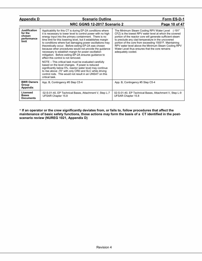
Appendix D Scenario Outline Form ES-D-1 NRC GGNS 12-2017 Scenario 2 Page 10 of 47
Revision 4
Justification for the chosen performance limit
Applicability for this CT is during EP-2A conditions where it is necessary to lower level to control power with no high energy input into the primary containment. There is no time limit for this lowering level, but it establishes margin to conditions where fuel damaging power oscillations may theoretically occur. Before exiting EP-2A was chosen because other procedures would not provide the guidance necessary to establish margin for power oscillation mitigation. Before exiting EP-2A ensures guidance to effect this control is not removed. NOTE – This critical task must be evaluated carefully based on the level changes. If power is reduced significantly below 5%, reactor water level may continue to rise above -70” with only CRD and SLC while driving control rods. This would not result in an UNSAT on this critical task.
The Minimum Steam Cooling RPV Water Level (-191” CFZ) is the lowest RPV water level at which the covered portion of the reactor core will generate sufficient steam to preclude any clad temperature in the uncovered portion of the core from exceeding 1500°F. Maintaining RPV water level above the Minimum Steam Cooling RPV Water Level thus ensures that the core remains adequately cooled.
BWR Owners Group Appendix
App. B, Contingency #5 Step C5-4
App. B, Contingency #5 Step C5-4
Licensed Bases Documents
02-S-01-40, EP Technical Bases, Attachment V, Step L-7 UFSAR Chapter 15.8
02-S-01-40, EP Technical Bases, Attachment V, Step L-9 UFSAR Chapter 15.8
* If an operator or the crew significantly deviates from, or fails to, follow procedures that affect the maintenance of basic safety functions, those actions may form the basis of a CT identified in the post-scenario review (NUREG 1021, Appendix D)
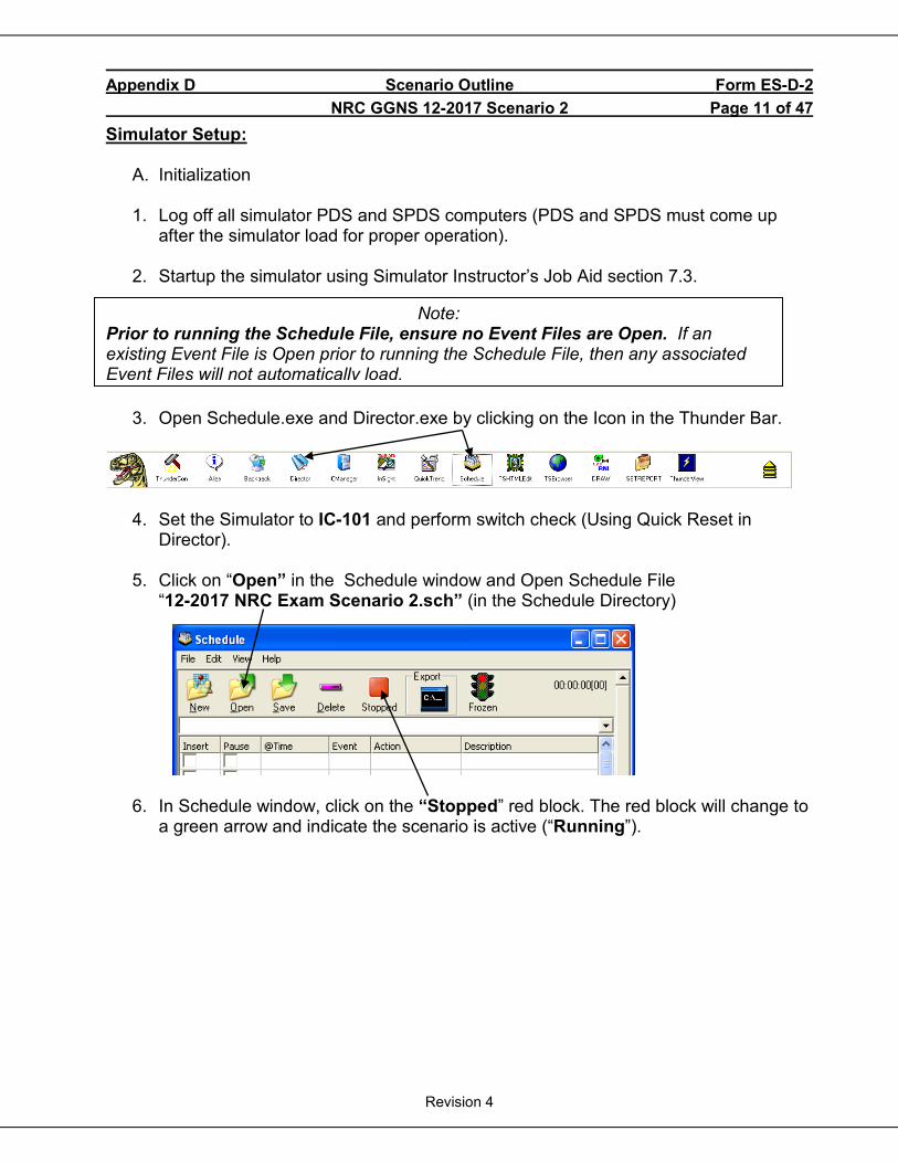
Appendix D Scenario Outline Form ES-D-2 NRC GGNS 12-2017 Scenario 2 Page 11 of 47
Revision 4
Simulator Setup:
A. Initialization
1. Log off all simulator PDS and SPDS computers (PDS and SPDS must come up after the simulator load for proper operation).
2. Startup the simulator using Simulator Instructor’s Job Aid section 7.3.
3. Open Schedule.exe and Director.exe by clicking on the Icon in the Thunder Bar.
4. Set the Simulator to IC-101 and perform switch check (Using Quick Reset in
Director). 5. Click on “Open” in the Schedule window and Open Schedule File
“12-2017 NRC Exam Scenario 2.sch” (in the Schedule Directory)
6. In Schedule window, click on the “Stopped” red block. The red block will change to
a green arrow and indicate the scenario is active (“Running”).
Note: Prior to running the Schedule File, ensure no Event Files are Open. If an existing Event File is Open prior to running the Schedule File, then any associated Event Files will not automatically load.
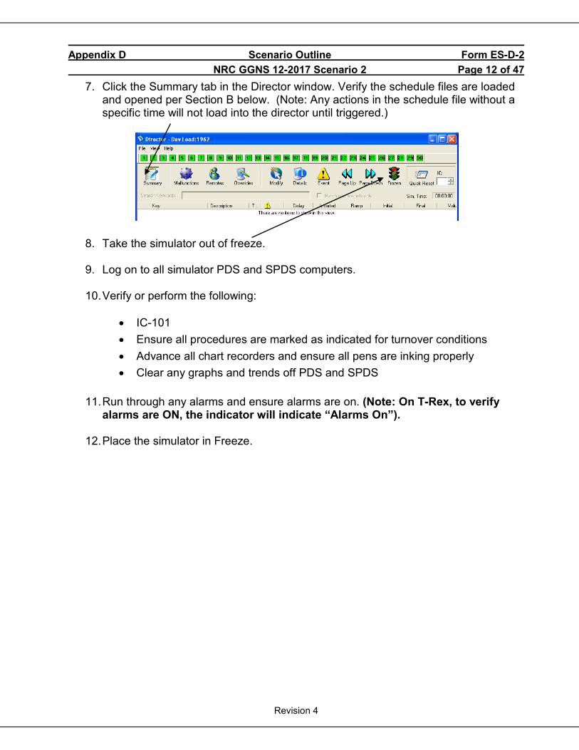
Appendix D Scenario Outline Form ES-D-2 NRC GGNS 12-2017 Scenario 2 Page 12 of 47
Revision 4
7. Click the Summary tab in the Director window. Verify the schedule files are loaded and opened per Section B below. (Note: Any actions in the schedule file without a specific time will not load into the director until triggered.)
8. Take the simulator out of freeze.
9. Log on to all simulator PDS and SPDS computers.
10. Verify or perform the following:
• IC-101 • Ensure all procedures are marked as indicated for turnover conditions • Advance all chart recorders and ensure all pens are inking properly • Clear any graphs and trends off PDS and SPDS
11. Run through any alarms and ensure alarms are on. (Note: On T-Rex, to verify
alarms are ON, the indicator will indicate “Alarms On”).
12. Place the simulator in Freeze.
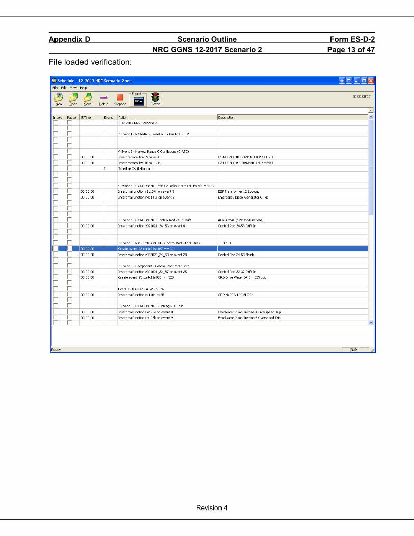
Appendix D Scenario Outline Form ES-D-2 NRC GGNS 12-2017 Scenario 2 Page 13 of 47
Revision 4
File loaded verification:
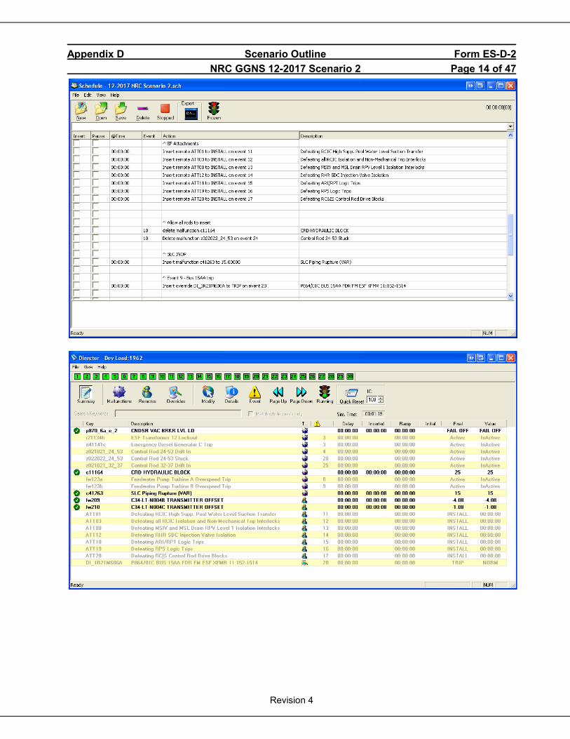
Appendix D Scenario Outline Form ES-D-2 NRC GGNS 12-2017 Scenario 2 Page 14 of 47
Revision 4
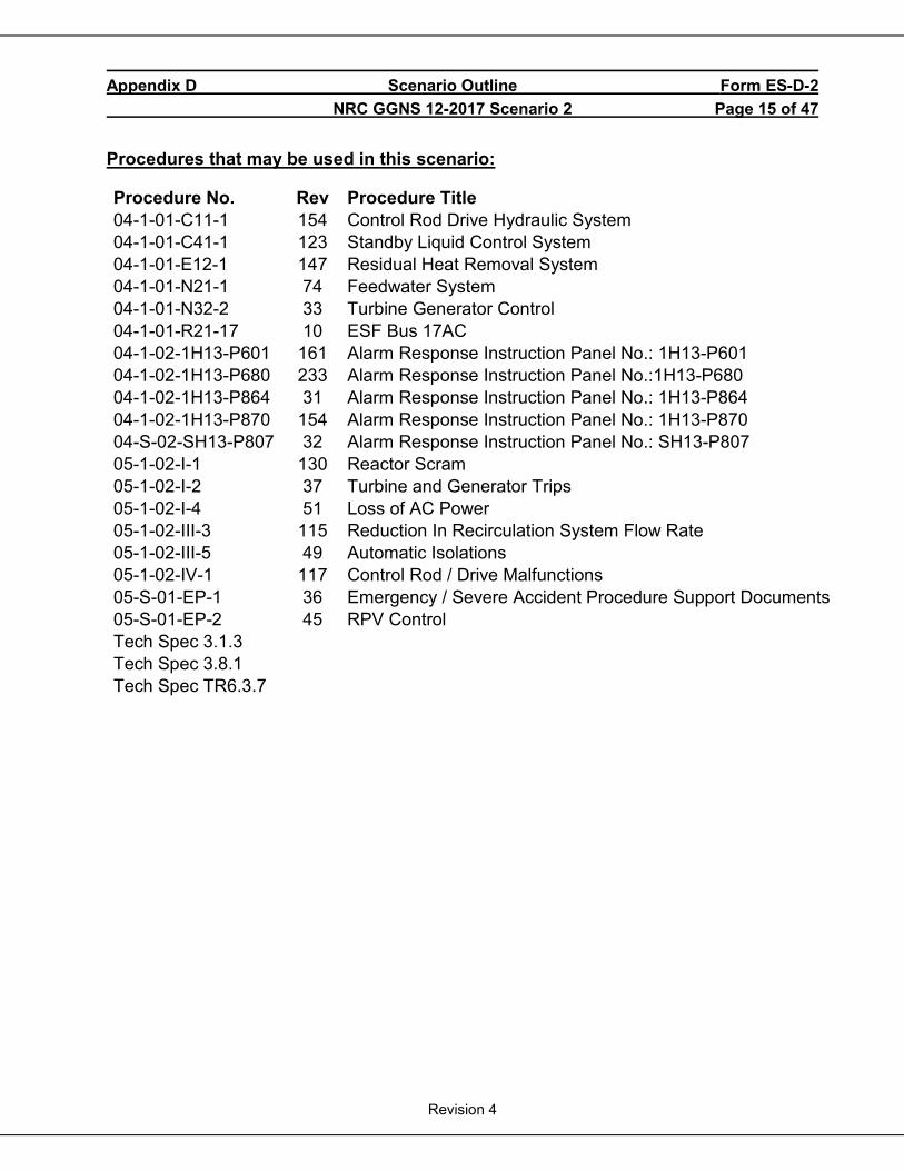
Appendix D Scenario Outline Form ES-D-2 NRC GGNS 12-2017 Scenario 2 Page 15 of 47
Revision 4
Procedures that may be used in this scenario:
Procedure No. Rev Procedure Title 04-1-01-C11-1 154 Control Rod Drive Hydraulic System 04-1-01-C41-1 123 Standby Liquid Control System 04-1-01-E12-1 147 Residual Heat Removal System 04-1-01-N21-1 74 Feedwater System 04-1-01-N32-2 33 Turbine Generator Control 04-1-01-R21-17 10 ESF Bus 17AC 04-1-02-1H13-P601 161 Alarm Response Instruction Panel No.: 1H13-P601 04-1-02-1H13-P680 233 Alarm Response Instruction Panel No.:1H13-P680 04-1-02-1H13-P864 31 Alarm Response Instruction Panel No.: 1H13-P864 04-1-02-1H13-P870 154 Alarm Response Instruction Panel No.: 1H13-P870 04-S-02-SH13-P807 32 Alarm Response Instruction Panel No.: SH13-P807 05-1-02-I-1 130 Reactor Scram 05-1-02-I-2 37 Turbine and Generator Trips 05-1-02-I-4 51 Loss of AC Power 05-1-02-III-3 115 Reduction In Recirculation System Flow Rate 05-1-02-III-5 49 Automatic Isolations 05-1-02-IV-1 117 Control Rod / Drive Malfunctions 05-S-01-EP-1 36 Emergency / Severe Accident Procedure Support Documents 05-S-01-EP-2 45 RPV Control Tech Spec 3.1.3 Tech Spec 3.8.1 Tech Spec TR6.3.7
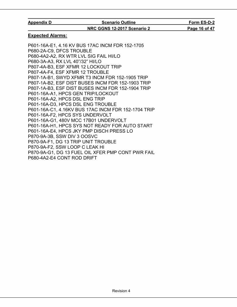
Appendix D Scenario Outline Form ES-D-2 NRC GGNS 12-2017 Scenario 2 Page 16 of 47
Revision 4
Expected Alarms:
P601-16A-E1, 4.16 KV BUS 17AC INCM FDR 152-1705 P680-2A-C9, DFCS TROUBLE P680-4A2-A2, RX WTR LVL SIG FAIL HI/LO P680-3A-A3, RX LVL 40”/32” HI/LO P807-4A-B3, ESF XFMR 12 LOCKOUT TRIP P807-4A-F4, ESF XFMR 12 TROUBLE P807-1A-B1, SWYD XFMR T3 INCM FDR 152-1905 TRIP P807-1A-B2, ESF DIST BUSES INCM FDR 152-1903 TRIP P807-1A-B3, ESF DIST BUSES INCM FDR 152-1904 TRIP P601-16A-A1, HPCS GEN TRIP/LOCKOUT P601-16A-A2, HPCS DSL ENG TRIP P601-16A-D3, HPCS DSL ENG TROUBLE P601-16A-C1, 4.16KV BUS 17AC INCM FDR 152-1704 TRIP P601-16A-F2, HPCS SYS UNDERVOLT P601-16A-G1, 480V MCC 17B01 UNDERVOLT P601-16A-H1, HPCS SYS NOT READY FOR AUTO START P601-16A-E4, HPCS JKY PMP DISCH PRESS LO P870-9A-3B, SSW DIV 3 OOSVC P870-9A-F1, DG 13 TRIP UNIT TROUBLE P870-9A-F2, SSW LOOP C LEAK HI P870-9A-G1, DG 13 FUEL OIL XFER PMP CONT PWR FAIL P680-4A2-E4 CONT ROD DRIFT

Appendix D Scenario Outline Form ES-D-2 NRC GGNS 12-2017 Scenario 2 Page 17 of 47
Revision 4
SCENARIO ACTIVITIES:
• Start SBT report and any other required recording devices.
Op-Test No: NRC LOT 12-2017 Scenario No: 2 Event No: 1 Event Description: Transfer Bus 17AC from ESF Transformer 21 to ESF Transformer 12.
TIME Position Applicant’s Actions or Behavior
BOP
Transfers ESF Bus 17AC from ESF Transformer 21 to ESF Transformer 12 IAW SOI 04-1-01-R21-17, ESF Bus 17AC, Section 4.2: 4.2.2.a Ensure XFMR ESF 12 energized up to Bus Feeder 152-1704 as follows: (1) Check closed J3885, 115kV FDR to XFMR ESF 12. (2) Check closed152-1904, FDR FRM XFMR ESF 12. (3) Check ENERGIZED status light is ON. 4.2.2.b Turn ON the Sync switch for 152-1704, Bus 17AC FDR FRM XFMR ESF
12. 4.2.2.c Check that the sync scope comes up to 12 o’clock ± 10°. 4.2.2.d If sources are in phase, then attempt to close 152-1704, Bus 17AC FDR
FRM XFMR ESF 12 If 152-1704 closes and the original feed breaker trips, then the bus is
energized and transfer is complete
• Annunciator P601-16A-E1, 4.16 KV BUS 17AC INCM FDR 152-1705 will alarm when breaker 152-1704 closes and breaker 152-1705 opens
4.2.2.d(1) Reset annunciator received for feeder tripping by taking the original tripped breaker handswitch to the TRIP position and releasing
4.2.2.d(2) Place Sync Switch to OFF Report to CRS that Bus 17AC has been transferred to ESF Transformer 12
END OF EVENT
Notes
Lead Examiner: Cue to proceed to the next event.
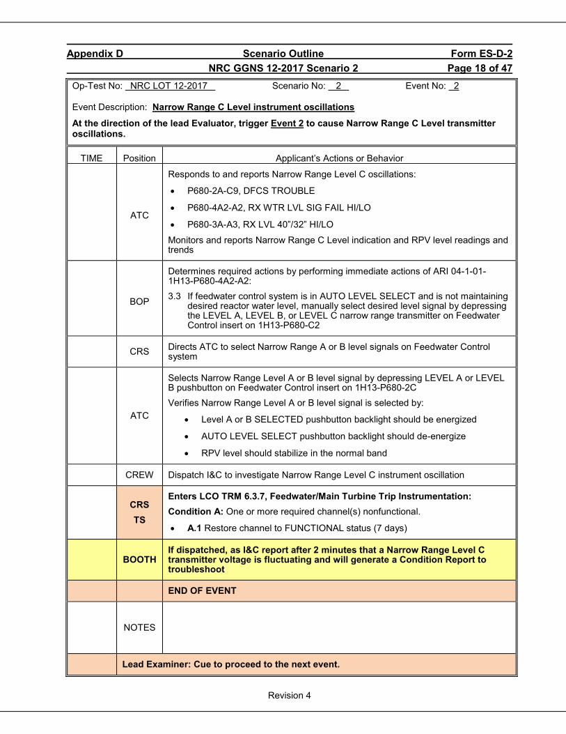
Appendix D Scenario Outline Form ES-D-2 NRC GGNS 12-2017 Scenario 2 Page 18 of 47
Revision 4
Op-Test No: NRC LOT 12-2017 Scenario No: 2 Event No: 2 Event Description: Narrow Range C Level instrument oscillations
At the direction of the lead Evaluator, trigger Event 2 to cause Narrow Range C Level transmitter oscillations.
TIME Position Applicant’s Actions or Behavior
ATC
Responds to and reports Narrow Range Level C oscillations:
• P680-2A-C9, DFCS TROUBLE
• P680-4A2-A2, RX WTR LVL SIG FAIL HI/LO
• P680-3A-A3, RX LVL 40”/32” HI/LO
Monitors and reports Narrow Range C Level indication and RPV level readings and trends
BOP
Determines required actions by performing immediate actions of ARI 04-1-01-1H13-P680-4A2-A2: 3.3 If feedwater control system is in AUTO LEVEL SELECT and is not maintaining
desired reactor water level, manually select desired level signal by depressing the LEVEL A, LEVEL B, or LEVEL C narrow range transmitter on Feedwater Control insert on 1H13-P680-C2
CRS Directs ATC to select Narrow Range A or B level signals on Feedwater Control system
ATC
Selects Narrow Range Level A or B level signal by depressing LEVEL A or LEVEL B pushbutton on Feedwater Control insert on 1H13-P680-2C Verifies Narrow Range Level A or B level signal is selected by:
• Level A or B SELECTED pushbutton backlight should be energized
• AUTO LEVEL SELECT pushbutton backlight should de-energize
• RPV level should stabilize in the normal band
CREW Dispatch I&C to investigate Narrow Range Level C instrument oscillation
CRS TS
Enters LCO TRM 6.3.7, Feedwater/Main Turbine Trip Instrumentation: Condition A: One or more required channel(s) nonfunctional.
• A.1 Restore channel to FUNCTIONAL status (7 days)
BOOTH
If dispatched, as I&C report after 2 minutes that a Narrow Range Level C transmitter voltage is fluctuating and will generate a Condition Report to troubleshoot
END OF EVENT
NOTES
Lead Examiner: Cue to proceed to the next event.
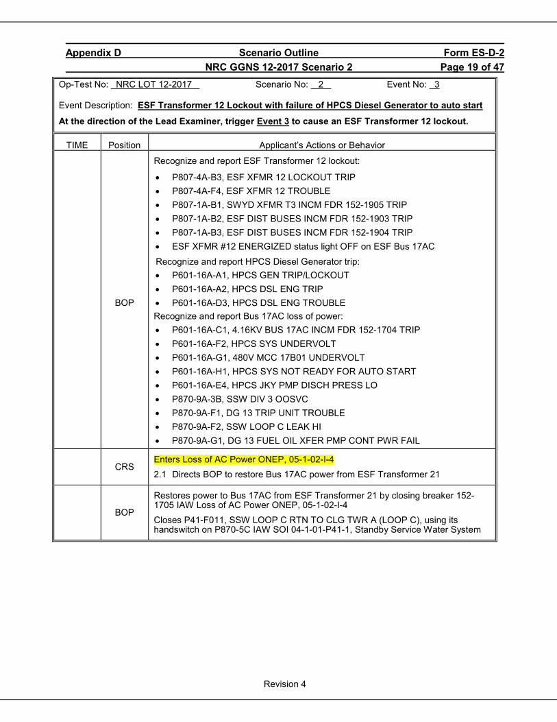
Appendix D Scenario Outline Form ES-D-2 NRC GGNS 12-2017 Scenario 2 Page 19 of 47
Revision 4
Op-Test No: NRC LOT 12-2017 Scenario No: 2 Event No: 3 Event Description: ESF Transformer 12 Lockout with failure of HPCS Diesel Generator to auto start
At the direction of the Lead Examiner, trigger Event 3 to cause an ESF Transformer 12 lockout.
TIME Position Applicant’s Actions or Behavior
BOP
Recognize and report ESF Transformer 12 lockout:
• P807-4A-B3, ESF XFMR 12 LOCKOUT TRIP • P807-4A-F4, ESF XFMR 12 TROUBLE • P807-1A-B1, SWYD XFMR T3 INCM FDR 152-1905 TRIP • P807-1A-B2, ESF DIST BUSES INCM FDR 152-1903 TRIP • P807-1A-B3, ESF DIST BUSES INCM FDR 152-1904 TRIP • ESF XFMR #12 ENERGIZED status light OFF on ESF Bus 17AC
Recognize and report HPCS Diesel Generator trip: • P601-16A-A1, HPCS GEN TRIP/LOCKOUT • P601-16A-A2, HPCS DSL ENG TRIP • P601-16A-D3, HPCS DSL ENG TROUBLE Recognize and report Bus 17AC loss of power: • P601-16A-C1, 4.16KV BUS 17AC INCM FDR 152-1704 TRIP • P601-16A-F2, HPCS SYS UNDERVOLT • P601-16A-G1, 480V MCC 17B01 UNDERVOLT • P601-16A-H1, HPCS SYS NOT READY FOR AUTO START • P601-16A-E4, HPCS JKY PMP DISCH PRESS LO • P870-9A-3B, SSW DIV 3 OOSVC • P870-9A-F1, DG 13 TRIP UNIT TROUBLE • P870-9A-F2, SSW LOOP C LEAK HI • P870-9A-G1, DG 13 FUEL OIL XFER PMP CONT PWR FAIL
CRS
Enters Loss of AC Power ONEP, 05-1-02-I-4 2.1 Directs BOP to restore Bus 17AC power from ESF Transformer 21
BOP
Restores power to Bus 17AC from ESF Transformer 21 by closing breaker 152-1705 IAW Loss of AC Power ONEP, 05-1-02-I-4 Closes P41-F011, SSW LOOP C RTN TO CLG TWR A (LOOP C), using its handswitch on P870-5C IAW SOI 04-1-01-P41-1, Standby Service Water System
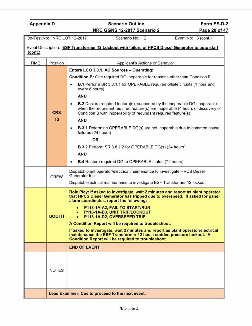
Appendix D Scenario Outline Form ES-D-2 NRC GGNS 12-2017 Scenario 2 Page 20 of 47
Revision 4
Op-Test No: NRC LOT 12-2017 Scenario No: 2 Event No: 3 (cont.) Event Description: ESF Transformer 12 Lockout with failure of HPCS Diesel Generator to auto start (cont.)
TIME Position Applicant’s Actions or Behavior
CRS TS
Enters LCO 3.8.1, AC Sources – Operating: Condition B: One required DG inoperable for reasons other than Condition F.
• B.1 Perform SR 3.8.1.1 for OPERABLE required offsite circuits (1 hour and every 8 hours)
AND
• B.2 Declare required feature(s), supported by the inoperable DG, inoperable when the redundant required feature(s) are inoperable (4 hours of discovery of Condition B with inoperability of redundant required feature(s)
AND
• B.3.1 Determine OPERABLE DG(s) are not inoperable due to common cause failures (24 hours)
OR
B.3.2 Perform SR 3.8.1.2 for OPERABLE DG(s) (24 hours)
AND
• B.4 Restore required DG to OPERABLE status (72 hours)
CREW
Dispatch plant operator/electrical maintenance to investigate HPCS Diesel Generator trip Dispatch electrical maintenance to investigate ESF Transformer 12 lockout
BOOTH
Role Play: If asked to investigate, wait 2 minutes and report as plant operator that HPCS Diesel Generator has tripped due to overspeed. If asked for panel alarm coordinates, report the following:
• P118-1A-A2, FAIL TO START/RUN • P118-1A-B3, UNIT TRIP/LOCKOUT • P118-1A-D2, OVERSPEED TRIP
A Condition Report will be required to troubleshoot. If asked to investigate, wait 2 minutes and report as plant operator/electrical maintenance the ESF Transformer 12 has a sudden pressure lockout. A Condition Report will be required to troubleshoot.
END OF EVENT
NOTES
Lead Examiner: Cue to proceed to the next event.
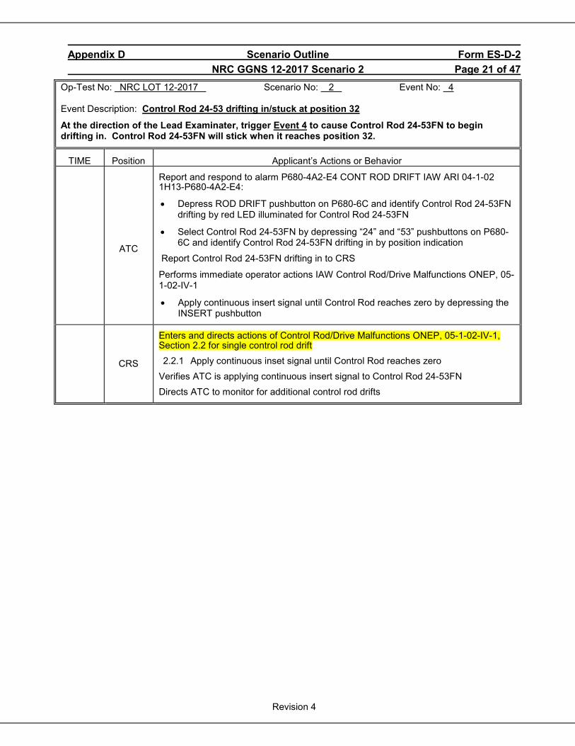
Appendix D Scenario Outline Form ES-D-2 NRC GGNS 12-2017 Scenario 2 Page 21 of 47
Revision 4
Op-Test No: NRC LOT 12-2017 Scenario No: 2 Event No: 4 Event Description: Control Rod 24-53 drifting in/stuck at position 32
At the direction of the Lead Examinater, trigger Event 4 to cause Control Rod 24-53FN to begin drifting in. Control Rod 24-53FN will stick when it reaches position 32.
TIME Position Applicant’s Actions or Behavior
ATC
Report and respond to alarm P680-4A2-E4 CONT ROD DRIFT IAW ARI 04-1-02 1H13-P680-4A2-E4:
• Depress ROD DRIFT pushbutton on P680-6C and identify Control Rod 24-53FN drifting by red LED illuminated for Control Rod 24-53FN
• Select Control Rod 24-53FN by depressing “24” and “53” pushbuttons on P680-6C and identify Control Rod 24-53FN drifting in by position indication
Report Control Rod 24-53FN drifting in to CRS
Performs immediate operator actions IAW Control Rod/Drive Malfunctions ONEP, 05-1-02-IV-1
• Apply continuous insert signal until Control Rod reaches zero by depressing the INSERT pushbutton
CRS
Enters and directs actions of Control Rod/Drive Malfunctions ONEP, 05-1-02-IV-1, Section 2.2 for single control rod drift 2.2.1 Apply continuous inset signal until Control Rod reaches zero
Verifies ATC is applying continuous insert signal to Control Rod 24-53FN Directs ATC to monitor for additional control rod drifts
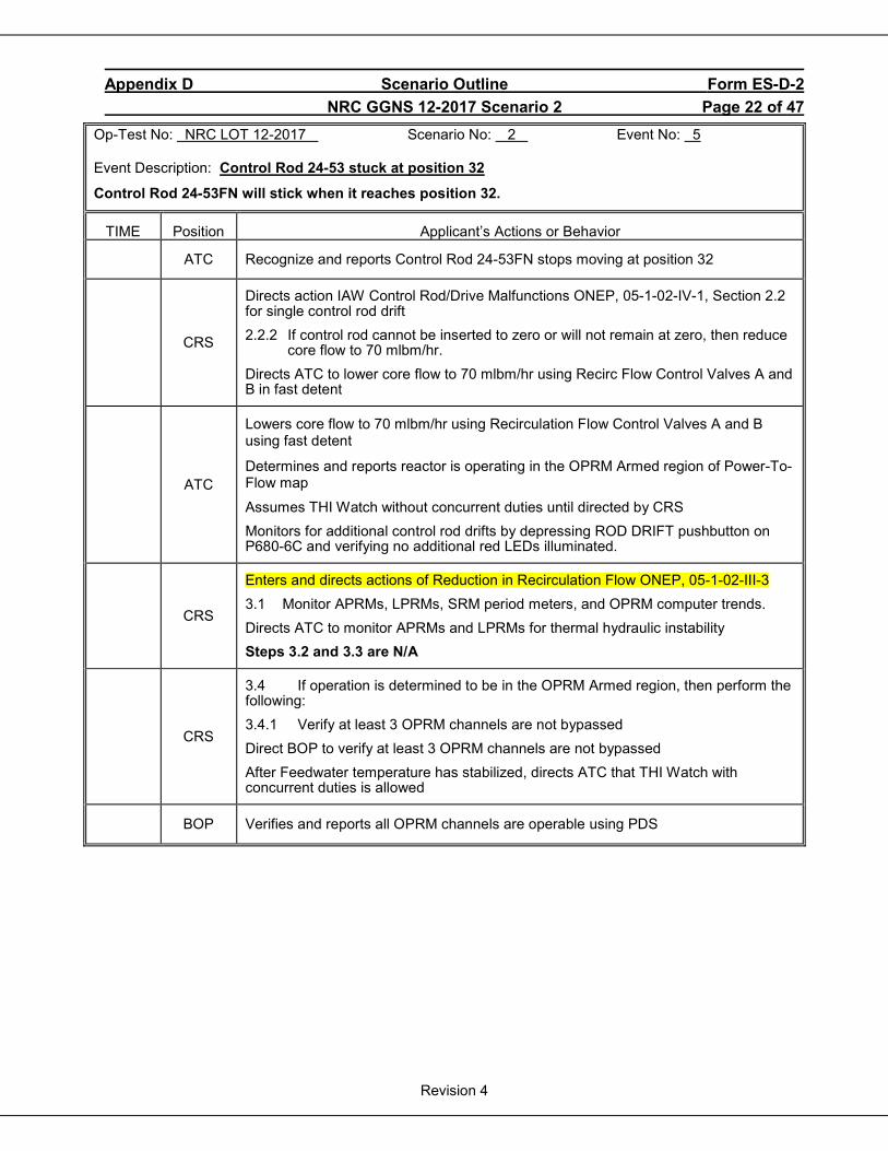
Appendix D Scenario Outline Form ES-D-2 NRC GGNS 12-2017 Scenario 2 Page 22 of 47
Revision 4
Op-Test No: NRC LOT 12-2017 Scenario No: 2 Event No: 5 Event Description: Control Rod 24-53 stuck at position 32
Control Rod 24-53FN will stick when it reaches position 32.
TIME Position Applicant’s Actions or Behavior
ATC Recognize and reports Control Rod 24-53FN stops moving at position 32
CRS
Directs action IAW Control Rod/Drive Malfunctions ONEP, 05-1-02-IV-1, Section 2.2 for single control rod drift 2.2.2 If control rod cannot be inserted to zero or will not remain at zero, then reduce
core flow to 70 mlbm/hr. Directs ATC to lower core flow to 70 mlbm/hr using Recirc Flow Control Valves A and B in fast detent
ATC
Lowers core flow to 70 mlbm/hr using Recirculation Flow Control Valves A and B using fast detent
Determines and reports reactor is operating in the OPRM Armed region of Power-To-Flow map
Assumes THI Watch without concurrent duties until directed by CRS Monitors for additional control rod drifts by depressing ROD DRIFT pushbutton on P680-6C and verifying no additional red LEDs illuminated.
CRS
Enters and directs actions of Reduction in Recirculation Flow ONEP, 05-1-02-III-3 3.1 Monitor APRMs, LPRMs, SRM period meters, and OPRM computer trends. Directs ATC to monitor APRMs and LPRMs for thermal hydraulic instability Steps 3.2 and 3.3 are N/A
CRS
3.4 If operation is determined to be in the OPRM Armed region, then perform the following: 3.4.1 Verify at least 3 OPRM channels are not bypassed Direct BOP to verify at least 3 OPRM channels are not bypassed After Feedwater temperature has stabilized, directs ATC that THI Watch with concurrent duties is allowed
BOP Verifies and reports all OPRM channels are operable using PDS

Appendix D Scenario Outline Form ES-D-2 NRC GGNS 12-2017 Scenario 2 Page 23 of 47
Revision 4
Op-Test No: NRC LOT 12-2017 Scenario No: 2 Event No: 5 (cont.) Event Description: Control Rod 24-53 stuck at position 32 (cont.)
TIME Position Applicant’s Actions or Behavior
CRS
Steps 3.5 and 3.6 are N/A 3.7 If both loops are operating, then perform the following
3.7.1 N/A 3.7.2 At less than 78.7 Mlbm/hr, balance loop flows to within 4460 gpm.
Directs ATC to verify Recirculation Loop flows are balanced within 4460 gpm
ATC Reports Recirc Loop A and B loop flows and verifies flows within 4460 gpm
CRS
Directs actions of Control Rod/Drive Malfunctions ONEP, 05-1-02-IV-1, Section 3.5 for inability to drive control rods 3.5.1 Directs BOP to verify CRD drive water pressure is equal to or greater than
260 psid
BOP
Verifies CRD drive water pressure is equal to or greater than 260 psig NOTE: BOP may adjust CRD drive water pressure by opening or closing C11-F003, CRD DRIVE WTR PRESS CONT VLV.
CRS 3.5.2 Direct BOP to verify stabilizing valves are operating properly and in-service FCV is operating properly
BOP
Verifies CRD stabilizing valves are operating properly by observing CRD DRIVE WTR HDR FLO A, B, C and D on panel P601 Contact plant operator to verify in-service CRD FCV is operating properly
BOOTH
Role Play: If asked to verify in-service CRD FCV is operating properly, wait 2 minutes and report using Plant Pager as plant operator that CRD FCV A appears to operating properly
CRS 3.5.3 Direct BOP to verify CRD suction flow path is adequate
BOP Verify CRD suction flow path is adequate by observing CRD system parameters on panel P601
CRS
3.5.4 Contact Reactor Engineering to determine if Control Rod 24-53FN has been identified as having excessive friction due to channel bow and to perform analysis for Control Rod 24-53 drifting in
BOOTH
Role Play: If contacted, as Reactor Engineering report that Control Rod 24-53FN HAS NOT been identified as having excessive friction due to channel bow and analysis will be done concerning Control Rod 24-53 drifting in
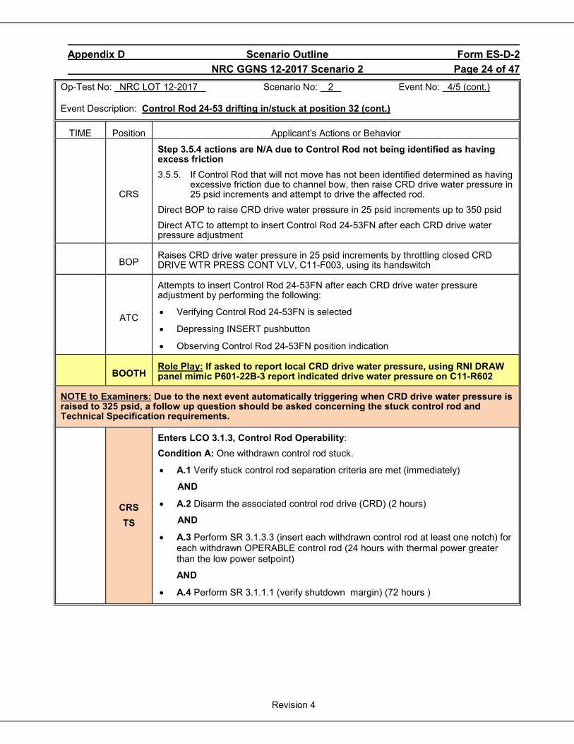
Appendix D Scenario Outline Form ES-D-2 NRC GGNS 12-2017 Scenario 2 Page 24 of 47
Revision 4
Op-Test No: NRC LOT 12-2017 Scenario No: 2 Event No: 4/5 (cont.) Event Description: Control Rod 24-53 drifting in/stuck at position 32 (cont.)
TIME Position Applicant’s Actions or Behavior
CRS
Step 3.5.4 actions are N/A due to Control Rod not being identified as having excess friction 3.5.5. If Control Rod that will not move has not been identified determined as having
excessive friction due to channel bow, then raise CRD drive water pressure in 25 psid increments and attempt to drive the affected rod.
Direct BOP to raise CRD drive water pressure in 25 psid increments up to 350 psid Direct ATC to attempt to insert Control Rod 24-53FN after each CRD drive water pressure adjustment
BOP
Raises CRD drive water pressure in 25 psid increments by throttling closed CRD DRIVE WTR PRESS CONT VLV, C11-F003, using its handswitch
ATC
Attempts to insert Control Rod 24-53FN after each CRD drive water pressure adjustment by performing the following:
• Verifying Control Rod 24-53FN is selected
• Depressing INSERT pushbutton
• Observing Control Rod 24-53FN position indication
BOOTH
Role Play: If asked to report local CRD drive water pressure, using RNI DRAW panel mimic P601-22B-3 report indicated drive water pressure on C11-R602
NOTE to Examiners: Due to the next event automatically triggering when CRD drive water pressure is raised to 325 psid, a follow up question should be asked concerning the stuck control rod and Technical Specification requirements.
CRS TS
Enters LCO 3.1.3, Control Rod Operability: Condition A: One withdrawn control rod stuck.
• A.1 Verify stuck control rod separation criteria are met (immediately)
AND
• A.2 Disarm the associated control rod drive (CRD) (2 hours)
AND
• A.3 Perform SR 3.1.3.3 (insert each withdrawn control rod at least one notch) for each withdrawn OPERABLE control rod (24 hours with thermal power greater than the low power setpoint)
AND
• A.4 Perform SR 3.1.1.1 (verify shutdown margin) (72 hours )

Appendix D Scenario Outline Form ES-D-2 NRC GGNS 12-2017 Scenario 2 Page 25 of 47
Revision 4
Op-Test No: NRC LOT 12-2017 Scenario No: 2 Event No: 4/5 (cont.) Event Description: Control Rod 24-53 drifting in/stuck at position 32 (cont.)
TIME Position Applicant’s Actions or Behavior
END OF EVENT
Notes
NOTE To Examiners: When CRD drive water pressure is raised to 325 psid, the next event will automatically trigger, causing a Control Rod 32-37HJ to begin drifting in. At the discretion of the Lead Examiner, the next event can be manually triggered before CRD drive water pressure reaches 325 psid.
Appendix D Scenario Outline Form ES-D-2 NRC GGNS 12-2017 Scenario 2 Page 26 of 47
Revision 4
Op-Test No: NRC LOT 12-2017 Scenario No: 2 Event No: 6 Event Description: Control Rod 32-37HJ drifting in (second control rod drift)
When CRD drive water pressure is raised to 325 psid, Control Rod 32-37HJ will begin drifting in.
TIME Position Applicant’s Actions or Behavior
ATC
Recognize and report second control rod (32-37HJ) drift
Performs immediate operator actions IAW Control Rod/Drive Malfunctions ONEP, 05-1-02-IV-1
2.3.1 Manually scram the reactor
Places Reactor Mode Switch to SHUTDOWN position
Recognize and report all control rods not inserted due to a hydraulic block ATWS
CRS
Directs ATC to insert a manual scram IAW Control Rod/Drive Malfunctions ONEP, 05-1-02-IV-1, immediate operator actions
Enters Reactor Scram ONEP, 05-1-02-I-1, Turbine and Generator Trips ONEP, 05-1-02-I-2, and EP-2, RPV Control
Directs all personnel to evacuate Containment due to reactor scram
END OF EVENT
Notes
NOTE to Examiners: The next event (ATWS) is already active. CRS actions start on the next page of the Scenario Guide. ATC actions start of Page 35 of the Scenario Guide. BOP actions start on Page 44 of the Scenario Guide.
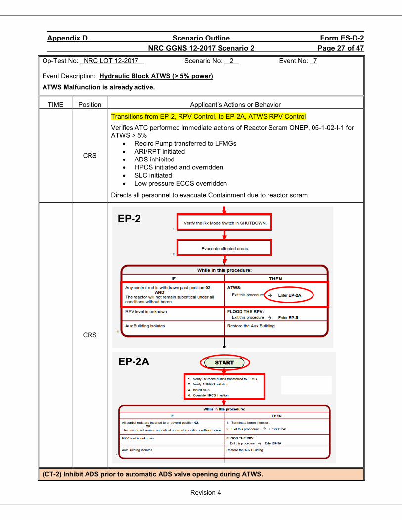
Appendix D Scenario Outline Form ES-D-2 NRC GGNS 12-2017 Scenario 2 Page 27 of 47
Revision 4
Op-Test No: NRC LOT 12-2017 Scenario No: 2 Event No: 7 Event Description: Hydraulic Block ATWS (> 5% power)
ATWS Malfunction is already active.
TIME Position Applicant’s Actions or Behavior
CRS
Transitions from EP-2, RPV Control, to EP-2A, ATWS RPV Control
Verifies ATC performed immediate actions of Reactor Scram ONEP, 05-1-02-I-1 for ATWS > 5%
• Recirc Pump transferred to LFMGs • ARI/RPT initiated • ADS inhibited • HPCS initiated and overridden • SLC initiated • Low pressure ECCS overridden
Directs all personnel to evacuate Containment due to reactor scram
CRS
(CT-2) Inhibit ADS prior to automatic ADS valve opening during ATWS.
EP-2
EP-2A

Appendix D Scenario Outline Form ES-D-2 NRC GGNS 12-2017 Scenario 2 Page 28 of 47
Revision 4
Op-Test No: NRC LOT 12-2017 Scenario No: 2 Event No: 7 (cont.) Event Description: Hydraulic Block ATWS (> 5% power) (cont.)
TIME Position Applicant’s Actions or Behavior
CRS
EP-2A
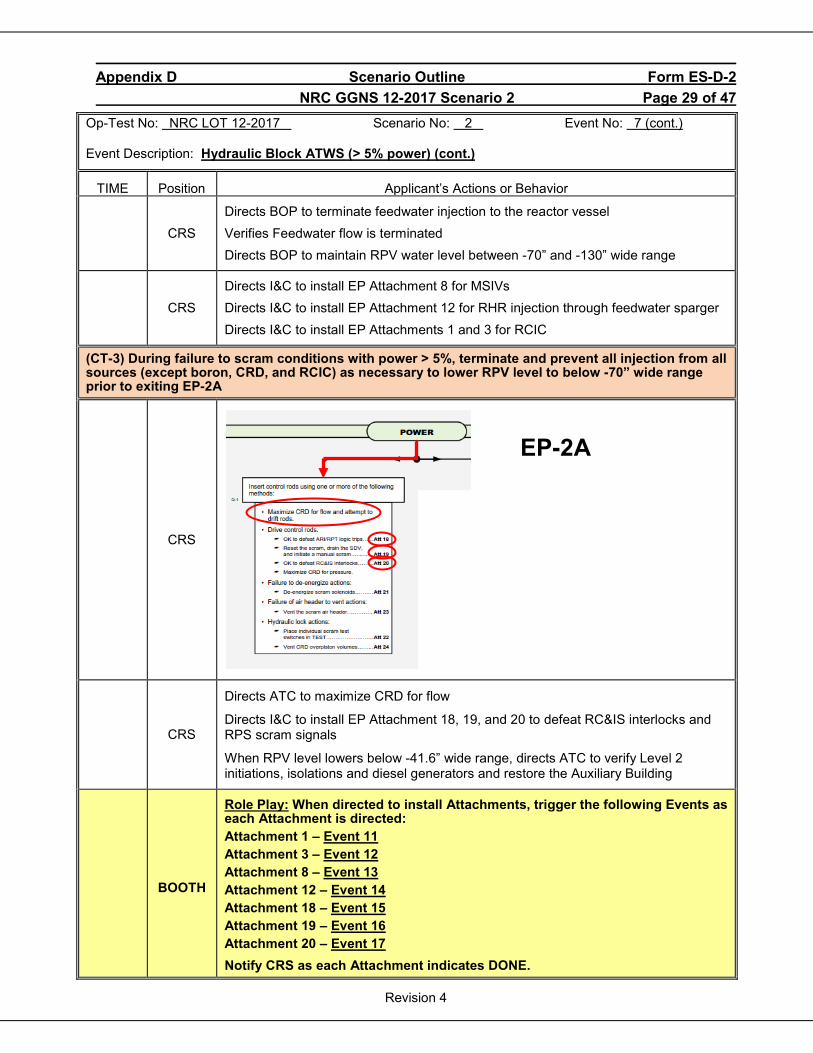
Appendix D Scenario Outline Form ES-D-2 NRC GGNS 12-2017 Scenario 2 Page 29 of 47
Revision 4
Op-Test No: NRC LOT 12-2017 Scenario No: 2 Event No: 7 (cont.) Event Description: Hydraulic Block ATWS (> 5% power) (cont.)
TIME Position Applicant’s Actions or Behavior
CRS Directs BOP to terminate feedwater injection to the reactor vessel Verifies Feedwater flow is terminated Directs BOP to maintain RPV water level between -70” and -130” wide range
CRS Directs I&C to install EP Attachment 8 for MSIVs Directs I&C to install EP Attachment 12 for RHR injection through feedwater sparger Directs I&C to install EP Attachments 1 and 3 for RCIC
(CT-3) During failure to scram conditions with power > 5%, terminate and prevent all injection from all sources (except boron, CRD, and RCIC) as necessary to lower RPV level to below -70” wide range prior to exiting EP-2A
CRS
CRS
Directs ATC to maximize CRD for flow
Directs I&C to install EP Attachment 18, 19, and 20 to defeat RC&IS interlocks and RPS scram signals
When RPV level lowers below -41.6” wide range, directs ATC to verify Level 2 initiations, isolations and diesel generators and restore the Auxiliary Building
BOOTH
Role Play: When directed to install Attachments, trigger the following Events as each Attachment is directed: Attachment 1 – Event 11 Attachment 3 – Event 12 Attachment 8 – Event 13 Attachment 12 – Event 14 Attachment 18 – Event 15 Attachment 19 – Event 16 Attachment 20 – Event 17 Notify CRS as each Attachment indicates DONE.
EP-2A
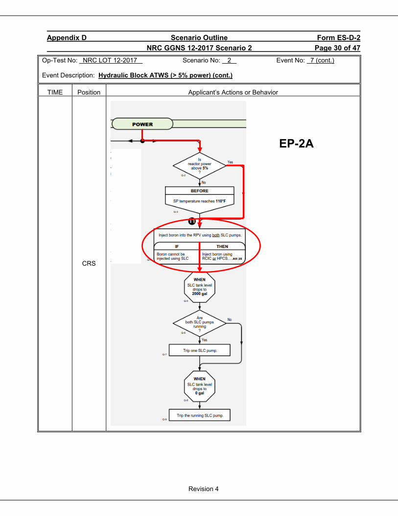
Appendix D Scenario Outline Form ES-D-2 NRC GGNS 12-2017 Scenario 2 Page 30 of 47
Revision 4
Op-Test No: NRC LOT 12-2017 Scenario No: 2 Event No: 7 (cont.) Event Description: Hydraulic Block ATWS (> 5% power) (cont.)
TIME Position Applicant’s Actions or Behavior
CRS
EP-2A
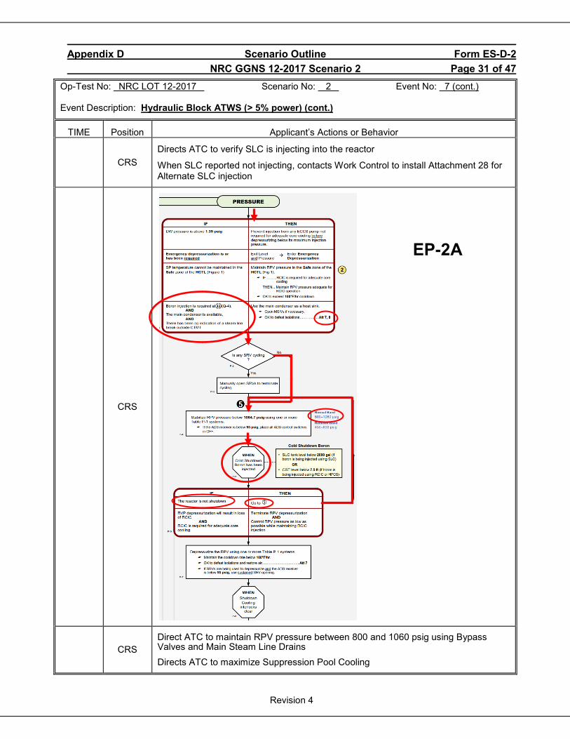
Appendix D Scenario Outline Form ES-D-2 NRC GGNS 12-2017 Scenario 2 Page 31 of 47
Revision 4
Op-Test No: NRC LOT 12-2017 Scenario No: 2 Event No: 7 (cont.) Event Description: Hydraulic Block ATWS (> 5% power) (cont.)
TIME Position Applicant’s Actions or Behavior
CRS
Directs ATC to verify SLC is injecting into the reactor
When SLC reported not injecting, contacts Work Control to install Attachment 28 for Alternate SLC injection
CRS
CRS Direct ATC to maintain RPV pressure between 800 and 1060 psig using Bypass Valves and Main Steam Line Drains Directs ATC to maximize Suppression Pool Cooling
EP-2A
Appendix D Scenario Outline Form ES-D-2 NRC GGNS 12-2017 Scenario 2 Page 32 of 47
Revision 4
Op-Test No: NRC LOT 12-2017 Scenario No: 2 Event No: 8 Event Description: Reactor Feed Pump trip
When reactor level has been lowered below -70” wide range and stable, at the direction of the Lead Examiner trigger Event 8 if RFPT A is being used for level control or Event 9 if RFPT B is being used.
TIME Position Applicant’s Actions or Behavior
BOP Recognize and report Reactor Feed Pump trip
CRS Directs BOP to start the standby Reactor Feed Pump IAW 04-1-01-E12-1, Attachment 6, per 02-S-01-43, Transient Mitigation Strategy
CREW Dispatch plant operator/maintenance to investigate Reactor Feed Pump trip
NOTE to Examiners: CRS may direct a reactor pressure reduction as follows to allow RPV injection with Condensate Booster Pumps instead of starting the standby Reactor Feed Pump.
CRS Directs ATC to lower reactor pressure to 450 – 600 psig using Bypass Jack IAW 02-S-01-43, Transient Mitigation Strategy
(CT-4) Restores injection using Condensate/Feedwater to restore/maintain RPV level above -191” CFZ before exiting EP-2A.

Appendix D Scenario Outline Form ES-D-2 NRC GGNS 12-2017 Scenario 2 Page 33 of 47
Revision 4
Op-Test No: NRC LOT 12-2017 Scenario No: 2 Event No: 9 Event Description: ESF Bus 15AA power loss
Before control rods are inserted, at the direction of the Lead Examiner, trigger Event 20 to trip feeder breaker 152-1514, BUS 15AA FDR FM ESF XFMR 11, causing a loss of power to ESF Bus 15AA. Div 1 DG will automatically start and restore power to ESF Bus 15AA
TIME Position Applicant’s Actions or Behavior
ATC
Recognize and report ESF Bus 15AA power loss and Div 1 Diesel Generator has restore ESF Bus 15AA power.
Recognize and report Division 1 ECCS overrides lost
Recognize and report Instrument Air isolation to Containment
CRS Directs ATC to override LPCS and RHR A pumps and valves IAW EP-2A
CRS Directs ATC to restore Instrument Air to Containment IAW EP-2A
CRS Directs ATC to maximize CRD flow IAW EP-2A

Appendix D Scenario Outline Form ES-D-2 NRC GGNS 12-2017 Scenario 2 Page 34 of 47
Revision 4
Op-Test No: NRC LOT 12-2017 Scenario No: 2 Event No: 7 (cont.) Event Description: Hydraulic Block ATWS (> 5% power) (cont.)
TIME Position Applicant’s Actions or Behavior
CRS When Attachments 18, 19, and 20 are installed, directs ATC to maximize CRD for pressure and scram and drive control rods
(CT-1) When control rods fail to scram, crew inserts all control rods to position 02 or beyond before exiting EP-2A.
BOOTH When control rod movement is reported to CRS, at the direction of the Lead Examiner, trigger Event 10 to allow all control rods to insert.
CRS
CRS When all control rods are inserted, exits EP-2A, ATWS RPV Control, and re-enters EP-2, RPV Control
CRS Directs BOP to restore and control RPV level between +11.4” to +53.5” narrow range
NOTE to Examiners: Scenario objectives have been met when the crew has inserted all control rods to position 02 or beyond, EP-2A is exited and level band has been changed to +11.4” to +53.5” narrow range.
END OF SCENARIO
Notes
BOOTH When directed by the Lead Examiner, place the simulator in freeze and tell the crew to stop operating.
Appendix D Scenario Outline Form ES-D-2 NRC GGNS 12-2017 Scenario 2 Page 35 of 47
Revision 4
Op-Test No: NRC LOT 12-2017 Scenario No: 2 Event No: 7 Event Description: Hydraulic Block ATWS (> 5% power)
ATC ACTIONS TIME Position Applicant’s Actions or Behavior
ATC
Performs immediate operator actions of Reactor Scram ONEP, 05-1-02-I-1:
2.1 Confirm all Control Rods are fully inserted
Recognize and report all not inserted due to a hydraulic block ATWS
2.2 Confirm reactor power decreasing
Report reactor power is greater than 5%
Steps 2.3 and 2.4 are N/A
ATC
2.5 If an ATWS occurs, the perform the following:
2.5.1 Verify Reactor Recirc Pumps are transferred to LFMGs
2.5.2 Initiate ARI/RPT
Arms and depresses ATWS ARI/RPT Channel 1 and Channel 2 pushbuttons
ATC 2.5.3 Inhibit ADS.
Places ADS A and ADS B MANUAL INHIBIT switches to INHIBIT position
ATC
2.5.4 Initiate and override HPCS IAW 02-S-01-43, Transient Mitigation Strategy.
While holding 1E22F004, HPCS INJ SHUTOFF VLV handswitch in CLOSE position, arm and depress manual system initiation pushbutton for HPCS
After indication of pump start, then trip HPCS Pump
Ensure HPCS Pump and 1E22F004, HPCS INJ SHUTOFF VLV override alarms are sealed in
(CT-2) Inhibit ADS prior to automatic ADS valve opening during ATWS.
(CT-3) During failure to scram conditions with power > 5%, terminate and prevent all injection from all sources (except boron, CRD, and RCIC) as necessary to lower RPV level to below -70” wide range
Appendix D Scenario Outline Form ES-D-2 NRC GGNS 12-2017 Scenario 2 Page 36 of 47
Revision 4
Op-Test No: NRC LOT 12-2017 Scenario No: 2 Event No: 7 (cont.) Event Description: Hydraulic Block ATWS (> 5% power) (cont.)
ATC ACTIONS TIME Position Applicant’s Actions or Behavior
ATC
2.5.5 If ATWS is greater than 5% power, then perform the following:
a. Initiate Standby Liquid Control.
Places SLC PMP A and SLC PMP B key-locked switches to START
b. Initiate and override low pressure ECCS IAW 02-S-01-43, Transient Mitigation Strategy, by performing the following:.
• Arms and depresses LPCS/RHR A MAN INIT pushbutton • After indication of LPCS and RHR A pump starts, then trip LPCS pump • Place LPCS and RHR A injection valve handswitches to CLOSE position • Ensure LPCS pump and LPCS and RHR A valve override alarms are sealed in • Arms and depresses RHR B/RHR C MAN INIT pushbutton • After indication of RHR B and RHR C pump starts, then trip RHR C pump • Close RHR B and RHR C injection valves • Ensure RHR C pump and RHR B and RHR C injection valve override alarms are
sealed in • Ensure associated Division 1 and 2 diesel generators are running with cooling
water
(CT-3) During failure to scram conditions with power > 5%, terminate and prevent all injection from all sources (except boron, CRD, and RCIC) as necessary to lower RPV level to below -70” wide range
Report to CRS that Reactor Scram immediate operator actions are complete except for maximizing Suppression Pool Cooling
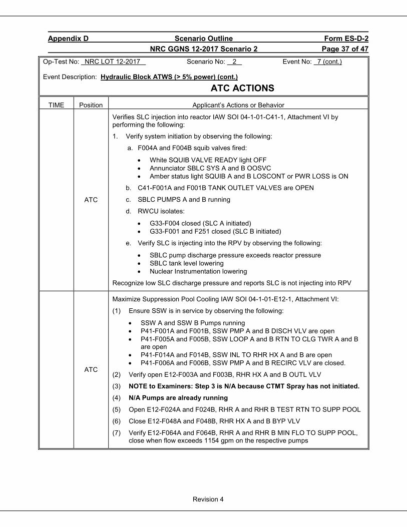
Appendix D Scenario Outline Form ES-D-2 NRC GGNS 12-2017 Scenario 2 Page 37 of 47
Revision 4
Op-Test No: NRC LOT 12-2017 Scenario No: 2 Event No: 7 (cont.) Event Description: Hydraulic Block ATWS (> 5% power) (cont.)
ATC ACTIONS TIME Position Applicant’s Actions or Behavior
ATC
Verifies SLC injection into reactor IAW SOI 04-1-01-C41-1, Attachment VI by performing the following:
1. Verify system initiation by observing the following:
a. F004A and F004B squib valves fired:
• White SQUIB VALVE READY light OFF • Annunciator SBLC SYS A and B OOSVC • Amber status light SQUIB A and B LOSCONT or PWR LOSS is ON
b. C41-F001A and F001B TANK OUTLET VALVES are OPEN
c. SBLC PUMPS A and B running
d. RWCU isolates:
• G33-F004 closed (SLC A initiated) • G33-F001 and F251 closed (SLC B initiated)
e. Verify SLC is injecting into the RPV by observing the following:
• SBLC pump discharge pressure exceeds reactor pressure • SBLC tank level lowering • Nuclear Instrumentation lowering
Recognize low SLC discharge pressure and reports SLC is not injecting into RPV
ATC
Maximize Suppression Pool Cooling IAW SOI 04-1-01-E12-1, Attachment VI:
(1) Ensure SSW is in service by observing the following:
• SSW A and SSW B Pumps running • P41-F001A and F001B, SSW PMP A and B DISCH VLV are open • P41-F005A and F005B, SSW LOOP A and B RTN TO CLG TWR A and B
are open • P41-F014A and F014B, SSW INL TO RHR HX A and B are open • P41-F006A and F006B, SSW PMP A and B RECIRC VLV are closed.
(2) Verify open E12-F003A and F003B, RHR HX A and B OUTL VLV
(3) NOTE to Examiners: Step 3 is N/A because CTMT Spray has not initiated.
(4) N/A Pumps are already running
(5) Open E12-F024A and F024B, RHR A and RHR B TEST RTN TO SUPP POOL
(6) Close E12-F048A and F048B, RHR HX A and B BYP VLV
(7) Verify E12-F064A and F064B, RHR A and RHR B MIN FLO TO SUPP POOL, close when flow exceeds 1154 gpm on the respective pumps
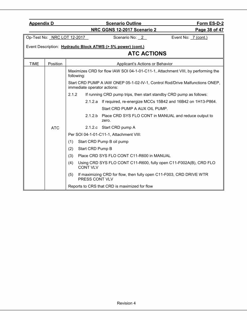
Appendix D Scenario Outline Form ES-D-2 NRC GGNS 12-2017 Scenario 2 Page 38 of 47
Revision 4
Op-Test No: NRC LOT 12-2017 Scenario No: 2 Event No: 7 (cont.) Event Description: Hydraulic Block ATWS (> 5% power) (cont.)
ATC ACTIONS TIME Position Applicant’s Actions or Behavior
ATC
Maximizes CRD for flow IAW SOI 04-1-01-C11-1, Attachment VIII, by performing the following:
Start CRD PUMP A IAW ONEP 05-1-02-IV-1, Control Rod/Drive Malfunctions ONEP, immediate operator actions:
2.1.2 If running CRD pump trips, then start standby CRD pump as follows:
2.1.2.a If required, re-energize MCCs 15B42 and 16B42 on 1H13-P864.
Start CRD PUMP A AUX OIL PUMP.
2.1.2.b Place CRD SYS FLO CONT in MANUAL and reduce output to zero.
2.1.2.c Start CRD pump A
Per SOI 04-1-01-C11-1, Attachment VIII:
(1) Start CRD Pump B oil pump
(2) Start CRD Pump B
(3) Place CRD SYS FLO CONT C11-R600 in MANUAL
(4) Using CRD SYS FLO CONT C11-R600, fully open C11-F002A(B), CRD FLO CONT VLV
(5) If maximizing CRD for flow, then fully open C11-F003, CRD DRIVE WTR PRESS CONT VLV
Reports to CRS that CRD is maximized for flow
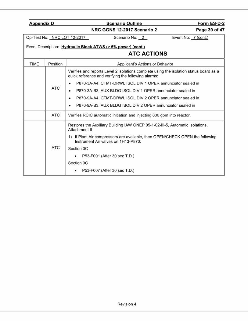
Appendix D Scenario Outline Form ES-D-2 NRC GGNS 12-2017 Scenario 2 Page 39 of 47
Revision 4
Op-Test No: NRC LOT 12-2017 Scenario No: 2 Event No: 7 (cont.) Event Description: Hydraulic Block ATWS (> 5% power) (cont.)
ATC ACTIONS TIME Position Applicant’s Actions or Behavior
ATC
Verifies and reports Level 2 isolations complete using the isolation status board as a quick reference and verifying the following alarms:
• P870-3A-A4, CTMT-DRWL ISOL DIV 1 OPER annunciator sealed in
• P870-3A-B3, AUX BLDG ISOL DIV 1 OPER annunciator sealed in
• P870-9A-A4, CTMT-DRWL ISOL DIV 2 OPER annunciator sealed in
• P870-9A-B3, AUX BLDG ISOL DIV 2 OPER annunciator sealed in
ATC Verifies RCIC automatic initiation and injecting 800 gpm into reactor.
ATC
Restores the Auxiliary Building IAW ONEP 05-1-02-III-5, Automatic Isolations, Attachment II
1) If Plant Air compressors are available, then OPEN/CHECK OPEN the following Instrument Air valves on 1H13-P870:
Section 3C
• P53-F001 (After 30 sec T.D.)
Section 9C
• P53-F007 (After 30 sec T.D.)
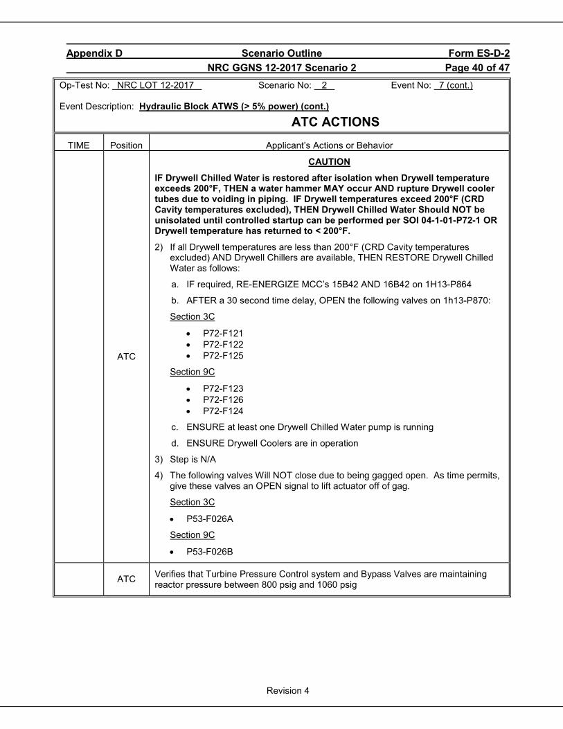
Appendix D Scenario Outline Form ES-D-2 NRC GGNS 12-2017 Scenario 2 Page 40 of 47
Revision 4
Op-Test No: NRC LOT 12-2017 Scenario No: 2 Event No: 7 (cont.) Event Description: Hydraulic Block ATWS (> 5% power) (cont.)
ATC ACTIONS TIME Position Applicant’s Actions or Behavior
ATC
CAUTION
IF Drywell Chilled Water is restored after isolation when Drywell temperature exceeds 200°F, THEN a water hammer MAY occur AND rupture Drywell cooler tubes due to voiding in piping. IF Drywell temperatures exceed 200°F (CRD Cavity temperatures excluded), THEN Drywell Chilled Water Should NOT be unisolated until controlled startup can be performed per SOI 04-1-01-P72-1 OR Drywell temperature has returned to < 200°F.
2) If all Drywell temperatures are less than 200°F (CRD Cavity temperatures excluded) AND Drywell Chillers are available, THEN RESTORE Drywell Chilled Water as follows:
a. IF required, RE-ENERGIZE MCC’s 15B42 AND 16B42 on 1H13-P864
b. AFTER a 30 second time delay, OPEN the following valves on 1h13-P870:
Section 3C
• P72-F121 • P72-F122 • P72-F125
Section 9C
• P72-F123 • P72-F126 • P72-F124
c. ENSURE at least one Drywell Chilled Water pump is running
d. ENSURE Drywell Coolers are in operation
3) Step is N/A
4) The following valves Will NOT close due to being gagged open. As time permits, give these valves an OPEN signal to lift actuator off of gag.
Section 3C
• P53-F026A
Section 9C
• P53-F026B
ATC Verifies that Turbine Pressure Control system and Bypass Valves are maintaining reactor pressure between 800 psig and 1060 psig
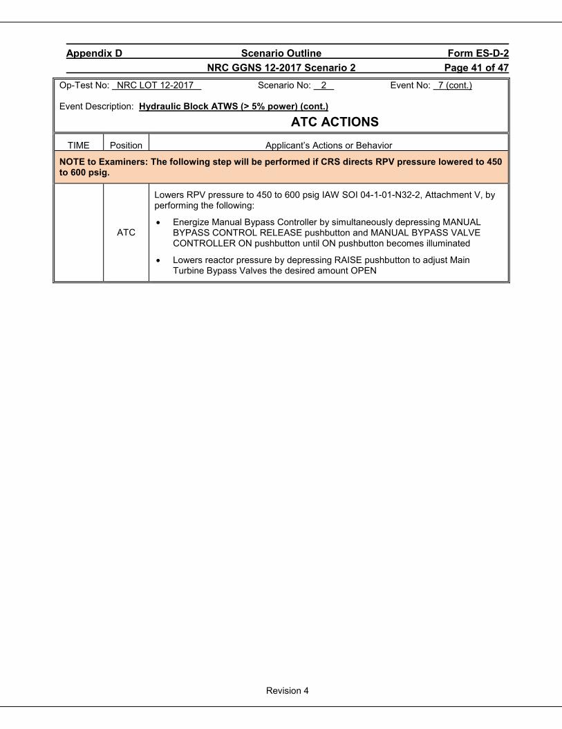
Appendix D Scenario Outline Form ES-D-2 NRC GGNS 12-2017 Scenario 2 Page 41 of 47
Revision 4
Op-Test No: NRC LOT 12-2017 Scenario No: 2 Event No: 7 (cont.) Event Description: Hydraulic Block ATWS (> 5% power) (cont.)
ATC ACTIONS TIME Position Applicant’s Actions or Behavior
NOTE to Examiners: The following step will be performed if CRS directs RPV pressure lowered to 450 to 600 psig.
ATC
Lowers RPV pressure to 450 to 600 psig IAW SOI 04-1-01-N32-2, Attachment V, by performing the following:
• Energize Manual Bypass Controller by simultaneously depressing MANUAL BYPASS CONTROL RELEASE pushbutton and MANUAL BYPASS VALVE CONTROLLER ON pushbutton until ON pushbutton becomes illuminated
• Lowers reactor pressure by depressing RAISE pushbutton to adjust Main Turbine Bypass Valves the desired amount OPEN
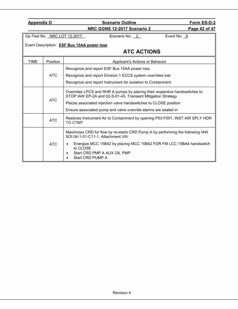
Appendix D Scenario Outline Form ES-D-2 NRC GGNS 12-2017 Scenario 2 Page 42 of 47
Revision 4
Op-Test No: NRC LOT 12-2017 Scenario No: 2 Event No: 9 Event Description: ESF Bus 15AA power loss
ATC ACTIONS TIME Position Applicant’s Actions or Behavior
ATC
Recognize and report ESF Bus 15AA power loss
Recognize and report Division 1 ECCS system overrides lost
Recognize and report Instrument Air isolation to Containment
ATC
Overrides LPCS and RHR A pumps by placing their respective handswitches to STOP IAW EP-2A and 02-S-01-43, Transient Mitigation Strategy
Places associated injection valve handswitches to CLOSE position
Ensure associated pump and valve override alarms are sealed in
ATC Restores Instrument Air to Containment by opening P53-F001, INST AIR SPLY HDR TO CTMT
ATC
Maximizes CRD for flow by re-starts CRD Pump A by performing the following IAW SOI 04-1-01-C11-1, Attachment VIII:
• Energize MCC 15B42 by placing MCC 15B42 FDR FM LCC 15BA4 handswitch to CLOSE
• Start CRD PMP A AUX OIL PMP • Start CRD PUMP A
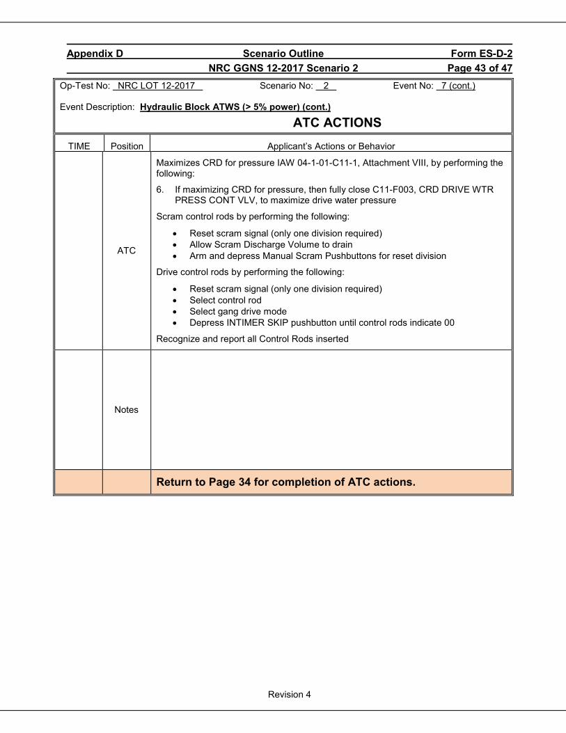
Appendix D Scenario Outline Form ES-D-2 NRC GGNS 12-2017 Scenario 2 Page 43 of 47
Revision 4
Op-Test No: NRC LOT 12-2017 Scenario No: 2 Event No: 7 (cont.) Event Description: Hydraulic Block ATWS (> 5% power) (cont.)
ATC ACTIONS TIME Position Applicant’s Actions or Behavior
ATC
Maximizes CRD for pressure IAW 04-1-01-C11-1, Attachment VIII, by performing the following:
6. If maximizing CRD for pressure, then fully close C11-F003, CRD DRIVE WTR PRESS CONT VLV, to maximize drive water pressure
Scram control rods by performing the following:
• Reset scram signal (only one division required) • Allow Scram Discharge Volume to drain • Arm and depress Manual Scram Pushbuttons for reset division
Drive control rods by performing the following:
• Reset scram signal (only one division required) • Select control rod • Select gang drive mode • Depress INTIMER SKIP pushbutton until control rods indicate 00
Recognize and report all Control Rods inserted
Notes
Return to Page 34 for completion of ATC actions.
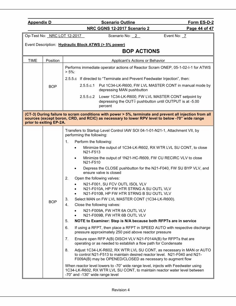
Appendix D Scenario Outline Form ES-D-2 NRC GGNS 12-2017 Scenario 2 Page 44 of 47
Revision 4
Op-Test No: NRC LOT 12-2017 Scenario No: 2 Event No: 7 Event Description: Hydraulic Block ATWS (> 5% power)
BOP ACTIONS TIME Position Applicant’s Actions or Behavior
BOP
Performs immediate operator actions of Reactor Scram ONEP, 05-1-02-I-1 for ATWS > 5%:
2.5.5.c If directed to “Terminate and Prevent Feedwater Injection”, then:
2.5.5.c.1 Put 1C34-LK-R600, FW LVL MASTER CONT in manual mode by depressing MAN pushbutton
2.5.5.c.2 Lower 1C34-LK-R600, FW LVL MASTER CONT setpoint by depressing the OUT⇓ pushbutton until OUTPUT is at -5.00 percent
(CT-3) During failure to scram conditions with power > 5%, terminate and prevent all injection from all sources (except boron, CRD, and RCIC) as necessary to lower RPV level to below -70” wide range prior to exiting EP-2A.
BOP
Transfers to Startup Level Control IAW SOI 04-1-01-N21-1, Attachment VII, by performing the following:
1. Perform the following: • Minimize the output of 1C34-LK-R602, RX WTR LVL SU CONT, to close
N21-F513 • Minimize the output of 1N21-HC-R609, FW CU RECIRC VLV to close
N21-F510 • Depress the CLOSE pushbutton for the N21-F040, FW SU BYP VLV, and
ensure valve is closed 2. Open the following valves:
• N21-F001, SU FCV OUTL ISOL VLV • N21-F010A, HP FW HTR STRNG A SU OUTL VLV • N21-F010B, HP FW HTR STRNG B SU OUTL VLV
3. Select MAN on FW LVL MASTER CONT (1C34-LK-R600). 4. Close the following valves:
• N21-F009A, FW HTR 6A OUTL VLV • N21-F009B, FW HTR 6B OUTL VLV
5. NOTE to Examiner: Step is N/A because both RFPTs are in service
6. If using a RFPT, then place a RFPT in SPEED AUTO with respective discharge pressure approximately 250 psid above reactor pressure
7. Ensure open RFP A(B) DISCH VLV N21-F014A(B) for RFPTs that are operating or as needed to establish a flow path for Condensate
8. Adjust 1C34-LK-R602, RX WTR LVL SU CONT, as necessary in MAN or AUTO to control N21-F513 to maintain desired reactor level. N21-F040 and N21-F009A(B) may be OPENED/CLOSED as necessary to augment flow
When reactor level lowers to -70” wide range level, injects with Feedwater using 1C34-LK-R602, RX WTR LVL SU CONT, to maintain reactor water level between -70” and -130” wide range level
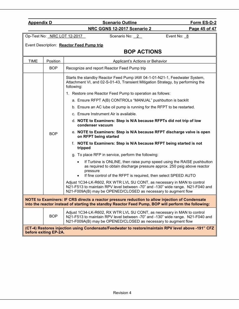
Appendix D Scenario Outline Form ES-D-2 NRC GGNS 12-2017 Scenario 2 Page 45 of 47
Revision 4
Op-Test No: NRC LOT 12-2017 Scenario No: 2 Event No: 8 Event Description: Reactor Feed Pump trip
BOP ACTIONS TIME Position Applicant’s Actions or Behavior
BOP Recognize and report Reactor Feed Pump trip
BOP
Starts the standby Reactor Feed Pump IAW 04-1-01-N21-1, Feedwater System, Attachment VI, and 02-S-01-43, Transient Mitigation Strategy, by performing the following:
1. Restore one Reactor Feed Pump to operation as follows:
a. Ensure RFPT A(B) CONTROLs “MANUAL” pushbutton is backlit
b. Ensure an AC lube oil pump is running for the RFPT to be restarted.
c. Ensure Instrument Air is available.
d. NOTE to Examiners: Step is N/A because RFPTs did not trip of low condenser vacuum
e. NOTE to Examiners: Step is N/A because RFPT discharge valve is open on RFPT being started
f. NOTE to Examiners: Step is N/A because RFPT being started is not tripped
g. To place RFP in service, perform the following:
• If Turbine is ONLINE, then raise pump speed using the RAISE pushbutton as required to obtain discharge pressure approx. 250 psig above reactor pressure
• If fine control of the RFPT is required, then select SPEED AUTO
Adjust 1C34-LK-R602, RX WTR LVL SU CONT, as necessary in MAN to control N21-F513 to maintain RPV level between -70” and -130” wide range. N21-F040 and N21-F009A(B) may be OPENED/CLOSED as necessary to augment flow
NOTE to Examiners: IF CRS directs a reactor pressure reduction to allow injection of Condensate into the reactor instead of starting the standby Reactor Feed Pump, BOP will perform the following:
BOP
Adjust 1C34-LK-R602, RX WTR LVL SU CONT, as necessary in MAN to control N21-F513 to maintain RPV level between -70” and -130” wide range. N21-F040 and N21-F009A(B) may be OPENED/CLOSED as necessary to augment flow
(CT-4) Restores injection using Condensate/Feedwater to restore/maintain RPV level above -191” CFZ before exiting EP-2A.
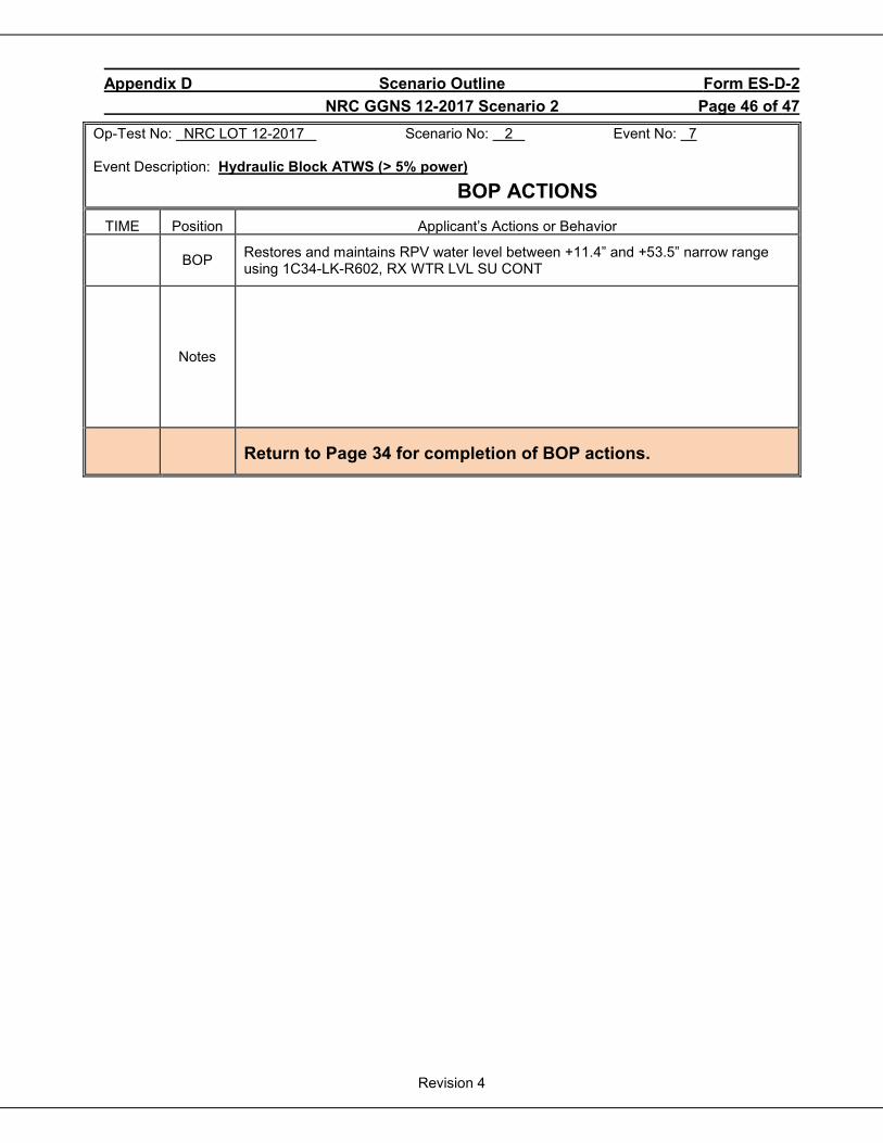
Appendix D Scenario Outline Form ES-D-2 NRC GGNS 12-2017 Scenario 2 Page 46 of 47
Revision 4
Op-Test No: NRC LOT 12-2017 Scenario No: 2 Event No: 7 Event Description: Hydraulic Block ATWS (> 5% power)
BOP ACTIONS TIME Position Applicant’s Actions or Behavior
BOP Restores and maintains RPV water level between +11.4” and +53.5” narrow range using 1C34-LK-R602, RX WTR LVL SU CONT
Notes
Return to Page 34 for completion of BOP actions.
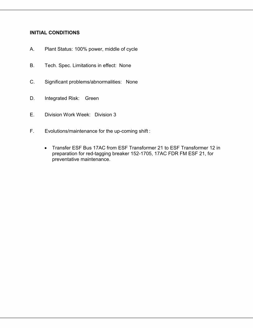
INITIAL CONDITIONS A. Plant Status: 100% power, middle of cycle B. Tech. Spec. Limitations in effect: None C. Significant problems/abnormalities: None D. Integrated Risk: Green E. Division Work Week: Division 3 F. Evolutions/maintenance for the up-coming shift :
• Transfer ESF Bus 17AC from ESF Transformer 21 to ESF Transformer 12 in preparation for red-tagging breaker 152-1705, 17AC FDR FM ESF 21, for preventative maintenance.
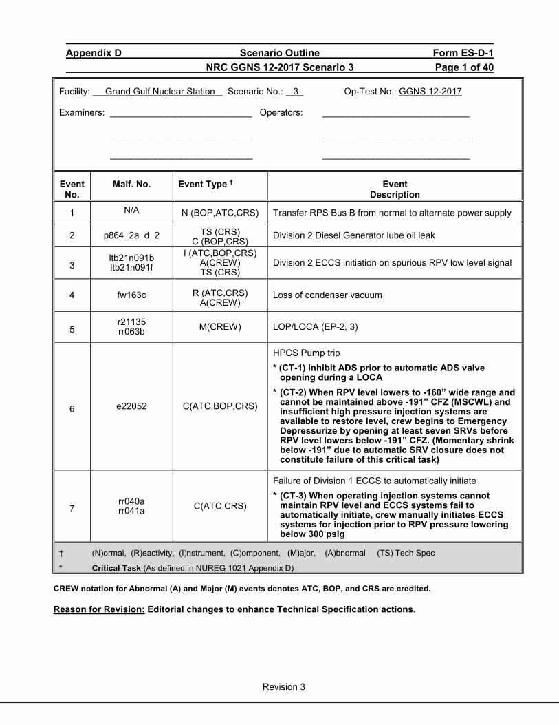
Appendix D Scenario Outline Form ES-D-1 NRC GGNS 12-2017 Scenario 3 Page 1 of 40
Revision 3
Facility: Grand Gulf Nuclear Station Scenario No.: 3 Op-Test No.: GGNS 12-2017 Examiners: ____________________________ Operators: _____________________________
____________________________ _____________________________ ____________________________ _____________________________
Event No.
Malf. No. Event Type † Event Description
1 N/A N (BOP,ATC,CRS) Transfer RPS Bus B from normal to alternate power supply
2 p864_2a_d_2 TS (CRS) C (BOP,CRS)
Division 2 Diesel Generator lube oil leak
3 ltb21n091b ltb21n091f
I (ATC,BOP,CRS) A(CREW) TS (CRS)
Division 2 ECCS initiation on spurious RPV low level signal
4 fw163c R (ATC,CRS) A(CREW)
Loss of condenser vacuum
5 r21135 rr063b M(CREW) LOP/LOCA (EP-2, 3)
6 e22052 C(ATC,BOP,CRS)
HPCS Pump trip * (CT-1) Inhibit ADS prior to automatic ADS valve
opening during a LOCA * (CT-2) When RPV level lowers to -160” wide range and
cannot be maintained above -191” CFZ (MSCWL) and insufficient high pressure injection systems are available to restore level, crew begins to Emergency Depressurize by opening at least seven SRVs before RPV level lowers below -191” CFZ. (Momentary shrink below -191” due to automatic SRV closure does not constitute failure of this critical task)
7 rr040a rr041a C(ATC,CRS)
Failure of Division 1 ECCS to automatically initiate * (CT-3) When operating injection systems cannot
maintain RPV level and ECCS systems fail to automatically initiate, crew manually initiates ECCS systems for injection prior to RPV pressure lowering below 300 psig
† (N)ormal, (R)eactivity, (I)nstrument, (C)omponent, (M)ajor, (A)bnormal (TS) Tech Spec
* Critical Task (As defined in NUREG 1021 Appendix D)
CREW notation for Abnormal (A) and Major (M) events denotes ATC, BOP, and CRS are credited.
Reason for Revision: Editorial changes to enhance Technical Specification actions.
Appendix D Scenario Outline Form ES-D-1 NRC GGNS 12-2017 Scenario 3 Page 2 of 40
Revision 3
Objectives: To evaluate the applicants’ ability to operate the facility in response to the following evolutions:
1. Transfer RPS Bus B from normal to alternate power supply. 2. Respond to a Division 2 Diesel Generator lube oil leak. 3. Respond to a Division 2 ECCS initiation on spurious RPV low level signal. 4. Respond to a loss of condenser vacuum. 5. Respond to a loss of Offsite Power / LOCA 6. Respond to a HPCS Pump trip. 7. Respond to a failure of Division 1 ECCS to automatically initiate.
Initial Conditions: Plant is operating at 100% power. Inoperable Equipment:
• TBCW Pump C is tagged out for motor oil replacement. • CRD Pump B is tagged out of service for oil replacement in the speed increaser.
Turnover: Planned activities for this shift are:
• Transfer RPS Bus B from normal to alternate power supply IAW SOI 04-1-01-C71-1, Section 5.1, in preparation for preventative maintenance on the RPS B Motor Generator.
• The Motor Generator will be tagged out on the next shift. • No scram or isolation surveillances are in progress or planned for this shift.
Scenario Notes: This scenario is a NEW Scenario. Validation Time: 75 minutes
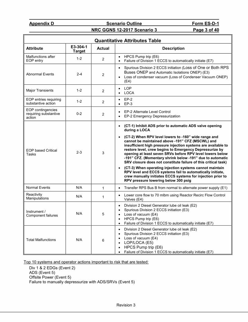
Appendix D Scenario Outline Form ES-D-1 NRC GGNS 12-2017 Scenario 3 Page 3 of 40
Revision 3
Quantitative Attributes Table Attribute E3-304-1
Target Actual Description
Malfunctions after EOP entry 1-2 2
• HPCS Pump trip (E6) • Failure of Division 1 ECCS to automatically initiate (E7)
Abnormal Events 2-4 2
• Spurious Division 2 ECCS initiation (Loss of One or Both RPS Buses ONEP and Automatic Isolations ONEP) (E3)
• Loss of condenser vacuum (Loss of Condenser Vacuum ONEP) (E4)
Major Transients 1-2 2 • LOP • LOCA
EOP entries requiring substantive action 1-2 2
• EP-2 • EP-3
EOP contingencies requiring substantive action
0-2 2 • EP-2 Alternate Level Control • EP-2 Emergency Depressurization
EOP based Critical Tasks 2-3 3
• (CT-1) Inhibit ADS prior to automatic ADS valve opening during a LOCA
• (CT-2) When RPV level lowers to -160” wide range and cannot be maintained above -191” CFZ (MSCWL) and insufficient high pressure injection systems are available to restore level, crew begins to Emergency Depressurize by opening at least seven SRVs before RPV level lowers below -191” CFZ. (Momentary shrink below -191” due to automatic SRV closure does not constitute failure of this critical task)
• (CT-3) When operating injection systems cannot maintain RPV level and ECCS systems fail to automatically initiate, crew manually initiates ECCS systems for injection prior to RPV pressure lowering below 300 psig
Normal Events N/A 1 • Transfer RPS Bus B from normal to alternate power supply (E1)
Reactivity Manipulations N/A 1 • Lower core flow to 70 mlbm using Reactor Recirc Flow Control
Valves (E4)
Instrument / Component failures N/A 5
• Division 2 Diesel Generator lube oil leak (E2) • Spurious Division 2 ECCS initiation (E3) • Loss of vacuum (E4) • HPCS Pump trip (E6) • Failure of Division 1 ECCS to automatically initiate (E7)
Total Malfunctions N/A 6
• Division 2 Diesel Generator lube oil leak (E2) • Spurious Division 2 ECCS initiation (E3) • Loss of vacuum (E4) • LOP/LOCA (E5) • HPCS Pump trip (E6) • Failure of Division 1 ECCS to automatically initiate (E7)
Top 10 systems and operator actions important to risk that are tested:
Div 1 & 2 EDGs (Event 2) ADS (Event 5) Offsite Power (Event 5) Failure to manually depressurize with ADS/SRVs (Event 5)
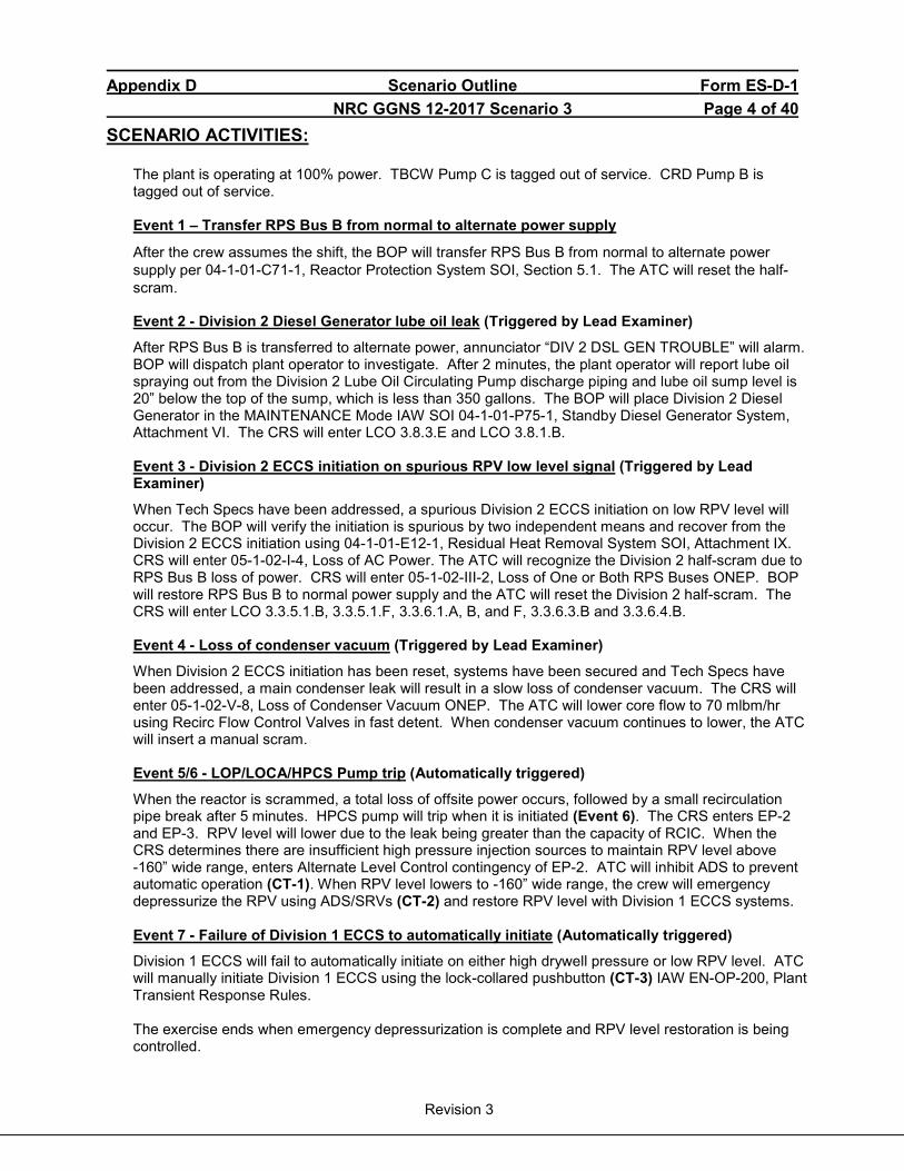
Appendix D Scenario Outline Form ES-D-1 NRC GGNS 12-2017 Scenario 3 Page 4 of 40
Revision 3
SCENARIO ACTIVITIES:
The plant is operating at 100% power. TBCW Pump C is tagged out of service. CRD Pump B is tagged out of service. Event 1 – Transfer RPS Bus B from normal to alternate power supply
After the crew assumes the shift, the BOP will transfer RPS Bus B from normal to alternate power supply per 04-1-01-C71-1, Reactor Protection System SOI, Section 5.1. The ATC will reset the half-scram. Event 2 - Division 2 Diesel Generator lube oil leak (Triggered by Lead Examiner)
After RPS Bus B is transferred to alternate power, annunciator “DIV 2 DSL GEN TROUBLE” will alarm. BOP will dispatch plant operator to investigate. After 2 minutes, the plant operator will report lube oil spraying out from the Division 2 Lube Oil Circulating Pump discharge piping and lube oil sump level is 20” below the top of the sump, which is less than 350 gallons. The BOP will place Division 2 Diesel Generator in the MAINTENANCE Mode IAW SOI 04-1-01-P75-1, Standby Diesel Generator System, Attachment VI. The CRS will enter LCO 3.8.3.E and LCO 3.8.1.B. Event 3 - Division 2 ECCS initiation on spurious RPV low level signal (Triggered by Lead Examiner)
When Tech Specs have been addressed, a spurious Division 2 ECCS initiation on low RPV level will occur. The BOP will verify the initiation is spurious by two independent means and recover from the Division 2 ECCS initiation using 04-1-01-E12-1, Residual Heat Removal System SOI, Attachment IX. CRS will enter 05-1-02-I-4, Loss of AC Power. The ATC will recognize the Division 2 half-scram due to RPS Bus B loss of power. CRS will enter 05-1-02-III-2, Loss of One or Both RPS Buses ONEP. BOP will restore RPS Bus B to normal power supply and the ATC will reset the Division 2 half-scram. The CRS will enter LCO 3.3.5.1.B, 3.3.5.1.F, 3.3.6.1.A, B, and F, 3.3.6.3.B and 3.3.6.4.B. Event 4 - Loss of condenser vacuum (Triggered by Lead Examiner)
When Division 2 ECCS initiation has been reset, systems have been secured and Tech Specs have been addressed, a main condenser leak will result in a slow loss of condenser vacuum. The CRS will enter 05-1-02-V-8, Loss of Condenser Vacuum ONEP. The ATC will lower core flow to 70 mlbm/hr using Recirc Flow Control Valves in fast detent. When condenser vacuum continues to lower, the ATC will insert a manual scram. Event 5/6 - LOP/LOCA/HPCS Pump trip (Automatically triggered)
When the reactor is scrammed, a total loss of offsite power occurs, followed by a small recirculation pipe break after 5 minutes. HPCS pump will trip when it is initiated (Event 6). The CRS enters EP-2 and EP-3. RPV level will lower due to the leak being greater than the capacity of RCIC. When the CRS determines there are insufficient high pressure injection sources to maintain RPV level above -160” wide range, enters Alternate Level Control contingency of EP-2. ATC will inhibit ADS to prevent automatic operation (CT-1). When RPV level lowers to -160” wide range, the crew will emergency depressurize the RPV using ADS/SRVs (CT-2) and restore RPV level with Division 1 ECCS systems. Event 7 - Failure of Division 1 ECCS to automatically initiate (Automatically triggered)
Division 1 ECCS will fail to automatically initiate on either high drywell pressure or low RPV level. ATC will manually initiate Division 1 ECCS using the lock-collared pushbutton (CT-3) IAW EN-OP-200, Plant Transient Response Rules. The exercise ends when emergency depressurization is complete and RPV level restoration is being controlled.
Appendix D Scenario Outline Form ES-D-1 NRC GGNS 12-2017 Scenario 3 Page 5 of 40
Revision 3
Critical Task (CT-1) Inhibit ADS prior to automatic ADS valve opening during a LOCA
(CT-2) When RPV level lowers to -160” wide range and cannot be maintained above -191” CFZ (MSCWL) and insufficient high pressure injection systems are available to restore level, crew begins to Emergency Depressurize by opening at least seven SRVs before RPV level lowers below -191” CFZ (Momentary shrink below -191” due to automatic SRV closure does not constitute failure of this critical task)
EVENT 6 6
Safety Significance
Permitting automatic ADS initiation may be undesirable for the following reasons: • ADS actuation can impose a severe thermal
transient on the RPV and may complicate efforts to control RPV water level.
• If only steam-driven systems are available for injection, ADS actuation may directly lead to loss of adequate core cooling and subsequent core damage.
• The conditions assumed in the design of the ADS actuation logic (e.g., no operator action for 115 seconds after event initiation) may not exist when the actions specified in this step are being performed.
• The operating crew can draw on much more information than is available to the ADS logic (e.g., equipment out of service for maintenance, operating experience with certain systems, probability of restoration of off-site power, etc.) and can better judge, based on instructions contained in the EPGs/SAGs, when and how to depressurize the RPV.
Defeating the logic relieves the operating crew of the task of detecting timer initiation during execution of the more complex steps of Contingency #1 and precludes unnecessary and unwanted automatic initiations. Subsequent steps provide explicit and detailed instructions for controlling RPV water level and specify when emergency depressurization is appropriate.
The MSCWL is the lowest RPV water level at which the covered portion of the reactor core will generate sufficient steam to preclude any clad temperature in the uncovered portion of the core from exceeding 1500°F. When water level decreases below MSCWL with injection, clad temperatures may exceed 1500°F.
Cueing Step L-5 of EP-2, RPV CONTROL, Alternate Level Control Contingency
Wide range indication (SPDS and PDS) falls to -160” and lowering trend continues, and, before -160” wide range is reached, initial conditions, field reports, and control room indications convey that adequate high pressure injection cannot be restored before level falls below -191” CFZ.
Performance Indicator
Manipulation of ADS A and ADS B MANUAL INHIBIT switches on panel P601 vertical section.
Manipulation of seven of the eight ADS/SRVs on panel P601: B21-F041K B21-F047L B21-F041F B21-F047A B21-F051C B21-F041D B21-F051A B21-F051B
Performance Feedback
Inhibit switches click into INHIBIT position on panel P601 vertical section. White indicating light on ADS A and ADS B MANUAL INHIBIT switches illuminate. Receipt of ADS/SRV A and ADS/SRV B OOSVC alarms on panel P601/18A-H2 and P601/19A-H2.
Crew will observe ADS/SRV light indication go from green to red, reactor pressure lowering on SPDS and panel P601 indications.
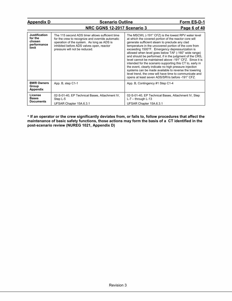
Appendix D Scenario Outline Form ES-D-1 NRC GGNS 12-2017 Scenario 3 Page 6 of 40
Revision 3
Justification for the chosen performance limit
The 115 second ADS timer allows sufficient time for the crew to recognize and override automatic operation of the system. As long as ADS is inhibited before ADS valves open, reactor pressure will not be reduced.
The MSCWL (-191” CFZ) is the lowest RPV water level at which the covered portion of the reactor core will generate sufficient steam to preclude any clad temperature in the uncovered portion of the core from exceeding 1500°F. Emergency depressurization is allowed when level goes below TAF (-160” wide range) and should be performed, if in the judgment of the CRS, level cannot be maintained above -191” CFZ. Since it is intended for the scenario supporting this CT to, early in the event, clearly indicate no high pressure injection systems can be made available to reverse the lowering level trend, the crew will have time to communicate and opens at least seven ADS/SRVs before -191” CFZ.
BWR Owners Group Appendix
App. B, step C1-1
App. B, Contingency #1 Step C1-4
License Bases Documents
02-S-01-40, EP Technical Bases, Attachment IV, Step L-5 UFSAR Chapter 15A.6.3.1
02-S-01-40, EP Technical Bases, Attachment IV, Step L-7 – through L-13 UFSAR Chapter 15A.6.3.1
* If an operator or the crew significantly deviates from, or fails to, follow procedures that affect the maintenance of basic safety functions, those actions may form the basis of a CT identified in the post-scenario review (NUREG 1021, Appendix D)

Appendix D Scenario Outline Form ES-D-1 NRC GGNS 12-2017 Scenario 3 Page 7 of 40
Revision 3
Critical Task (CT-3) When operating injection systems cannot maintain RPV level and ECCS systems fail to automatically initiate, crew manually initiates or aligns ECCS systems for injection prior to RPV pressure lowering below 300 psig
EVENT 7
Safety Significance
Failure to recognize the auto initiation not occurring, and failure to take manual action per Conduct of Ops will result in unavailability of safety-related equipment necessary to provide adequate core cooling, otherwise resulting in core damage and a large offsite release.
Cueing Indication of ECCS systems not initiating with initiation conditions present: • Indication of Drywell pressure ≥ 1.39 psig or
RPV level ≤ -150.3” wide range • White light on LPCS/RHR A INIT RESET
pushbutton extinguished on panel P601 • Green light on and red light extinguished on
LPCS and RHR A pump handswitches on panel P601
Performance Indicator
Operator manually initiates Division 1 ECCS by rotating the arming collar and depressing the LPCS/RHR A MAN INIT pushbutton on panel P601.
Performance Feedback
Red light on and green light extinguished on LPCS and RHR A pump handswitches on panel P601. Rising level trend on indications on panel P601, PDS and SPDS. Rising flow rate on LPCS and/or RHR A flow indicators on panel P601, PDS, and SPDS.
Justification for the chosen performance limit
Attempting to align high pressure ECCS systems must be performed to determine their availability by the time TAF is reached in order to properly implement EP-2 decision steps regarding restoring and maintaining RPV level. Attempting to align low pressure ECCS systems can only be done one RPV pressure falls below the injection valve RPV pressure permissive and will only be effective once RPV pressure falls below the shutoff head of the respective ECCS pump. The reduction in RPV pressure will normally be via Emergency Depressurization, which is a separate critical task bounded by a minimum RPV level.
BWR Owners Group Appendix
App. B, Contingency 1, step C1-3
License Bases Documents
02-S-01-40, EP Technical Bases, Attachment IV, Step L-14 UFSAR Chapter 15A.6.3.1
* If an operator or the crew significantly deviates from, or fails to, follow procedures that affect the maintenance of basic safety functions, those actions may form the basis of a CT identified in the post-scenario review (NUREG 1021, Appendix D)
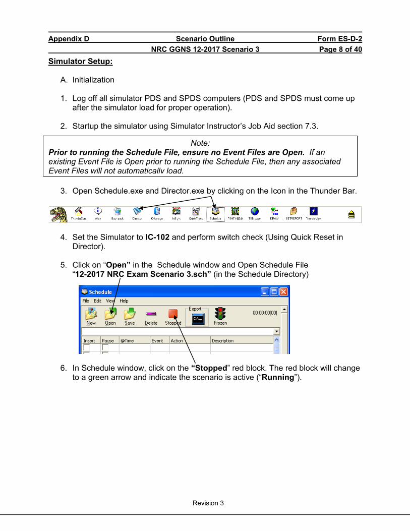
Appendix D Scenario Outline Form ES-D-2 NRC GGNS 12-2017 Scenario 3 Page 8 of 40
Revision 3
Simulator Setup:
A. Initialization
1. Log off all simulator PDS and SPDS computers (PDS and SPDS must come up after the simulator load for proper operation).
2. Startup the simulator using Simulator Instructor’s Job Aid section 7.3.
3. Open Schedule.exe and Director.exe by clicking on the Icon in the Thunder Bar.
4. Set the Simulator to IC-102 and perform switch check (Using Quick Reset in
Director). 5. Click on “Open” in the Schedule window and Open Schedule File
“12-2017 NRC Exam Scenario 3.sch” (in the Schedule Directory)
6. In Schedule window, click on the “Stopped” red block. The red block will change
to a green arrow and indicate the scenario is active (“Running”).
Note: Prior to running the Schedule File, ensure no Event Files are Open. If an existing Event File is Open prior to running the Schedule File, then any associated Event Files will not automatically load.
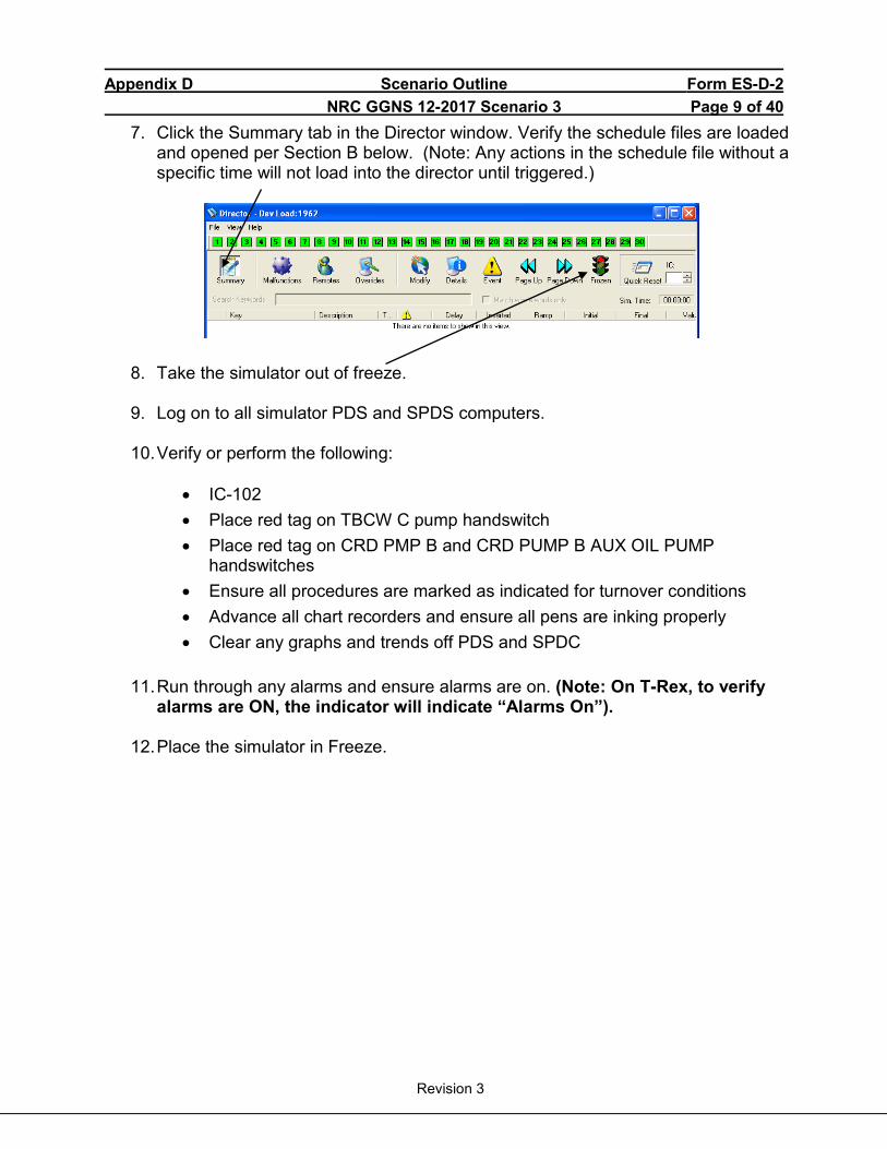
Appendix D Scenario Outline Form ES-D-2 NRC GGNS 12-2017 Scenario 3 Page 9 of 40
Revision 3
7. Click the Summary tab in the Director window. Verify the schedule files are loaded and opened per Section B below. (Note: Any actions in the schedule file without a specific time will not load into the director until triggered.)
8. Take the simulator out of freeze.
9. Log on to all simulator PDS and SPDS computers.
10. Verify or perform the following:
• IC-102 • Place red tag on TBCW C pump handswitch • Place red tag on CRD PMP B and CRD PUMP B AUX OIL PUMP
handswitches • Ensure all procedures are marked as indicated for turnover conditions • Advance all chart recorders and ensure all pens are inking properly • Clear any graphs and trends off PDS and SPDC
11. Run through any alarms and ensure alarms are on. (Note: On T-Rex, to verify
alarms are ON, the indicator will indicate “Alarms On”).
12. Place the simulator in Freeze.
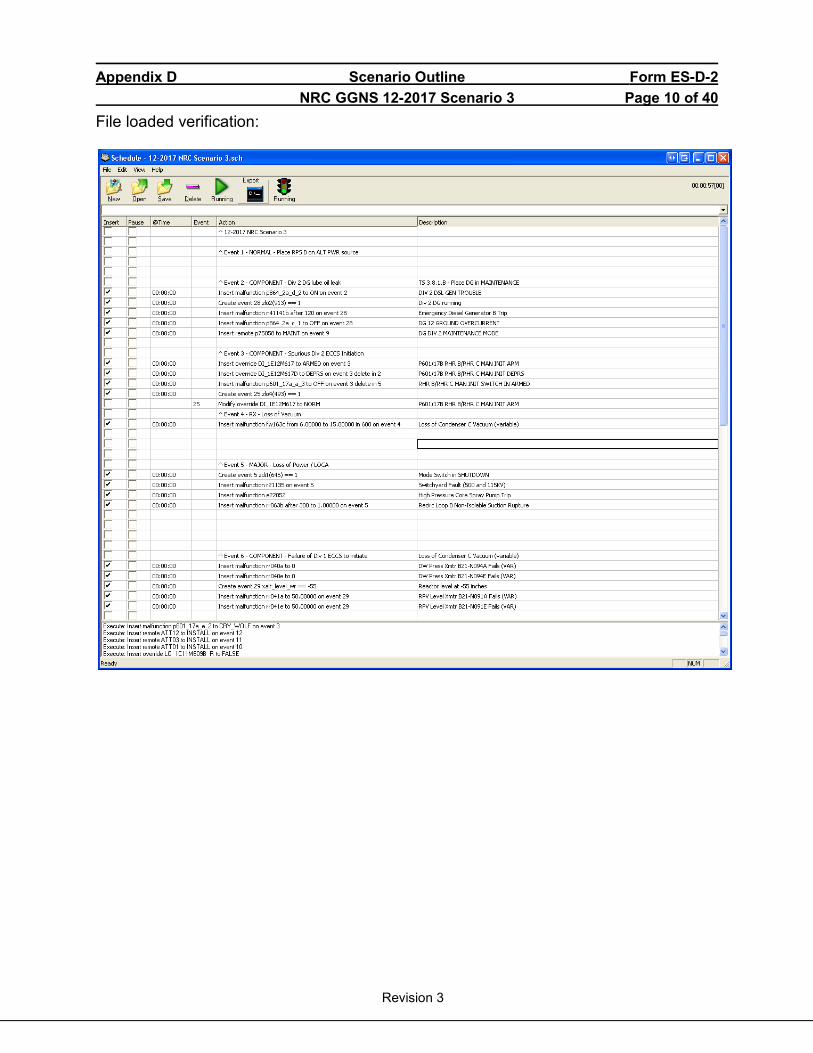
Appendix D Scenario Outline Form ES-D-2 NRC GGNS 12-2017 Scenario 3 Page 10 of 40
Revision 3
File loaded verification:
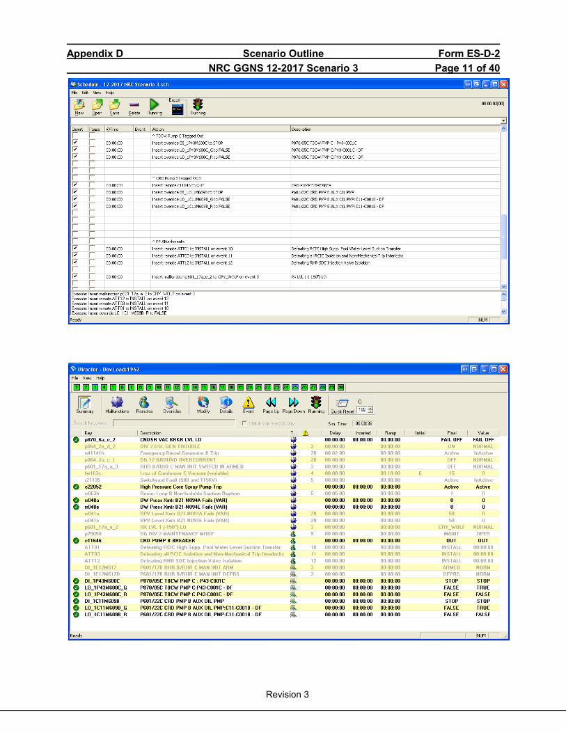
Appendix D Scenario Outline Form ES-D-2 NRC GGNS 12-2017 Scenario 3 Page 11 of 40
Revision 3
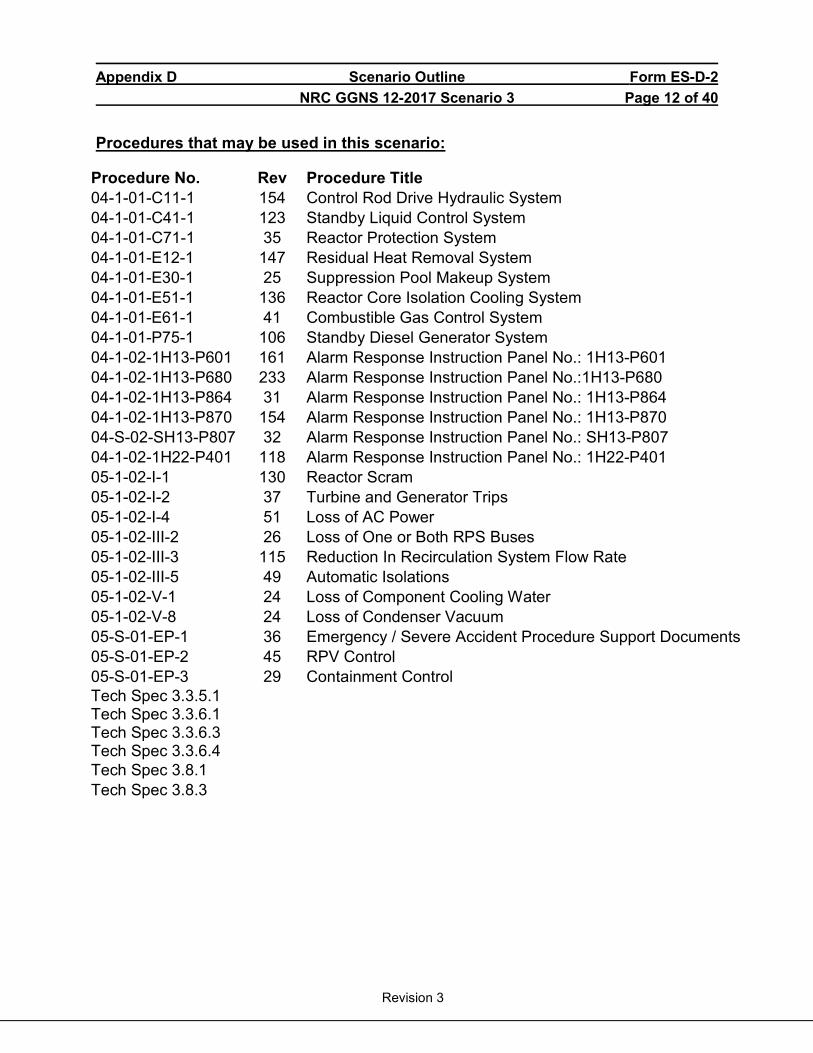
Appendix D Scenario Outline Form ES-D-2 NRC GGNS 12-2017 Scenario 3 Page 12 of 40
Revision 3
Procedures that may be used in this scenario:
Procedure No. Rev Procedure Title 04-1-01-C11-1 154 Control Rod Drive Hydraulic System 04-1-01-C41-1 123 Standby Liquid Control System 04-1-01-C71-1 35 Reactor Protection System 04-1-01-E12-1 147 Residual Heat Removal System 04-1-01-E30-1 25 Suppression Pool Makeup System 04-1-01-E51-1 136 Reactor Core Isolation Cooling System 04-1-01-E61-1 41 Combustible Gas Control System 04-1-01-P75-1 106 Standby Diesel Generator System 04-1-02-1H13-P601 161 Alarm Response Instruction Panel No.: 1H13-P601 04-1-02-1H13-P680 233 Alarm Response Instruction Panel No.:1H13-P680 04-1-02-1H13-P864 31 Alarm Response Instruction Panel No.: 1H13-P864 04-1-02-1H13-P870 154 Alarm Response Instruction Panel No.: 1H13-P870 04-S-02-SH13-P807 32 Alarm Response Instruction Panel No.: SH13-P807 04-1-02-1H22-P401 118 Alarm Response Instruction Panel No.: 1H22-P401 05-1-02-I-1 130 Reactor Scram 05-1-02-I-2 37 Turbine and Generator Trips 05-1-02-I-4 51 Loss of AC Power 05-1-02-III-2 26 Loss of One or Both RPS Buses 05-1-02-III-3 115 Reduction In Recirculation System Flow Rate 05-1-02-III-5 49 Automatic Isolations 05-1-02-V-1 24 Loss of Component Cooling Water 05-1-02-V-8 24 Loss of Condenser Vacuum 05-S-01-EP-1 36 Emergency / Severe Accident Procedure Support Documents 05-S-01-EP-2 45 RPV Control 05-S-01-EP-3 29 Containment Control Tech Spec 3.3.5.1 Tech Spec 3.3.6.1 Tech Spec 3.3.6.3 Tech Spec 3.3.6.4
Tech Spec 3.8.1 Tech Spec 3.8.3
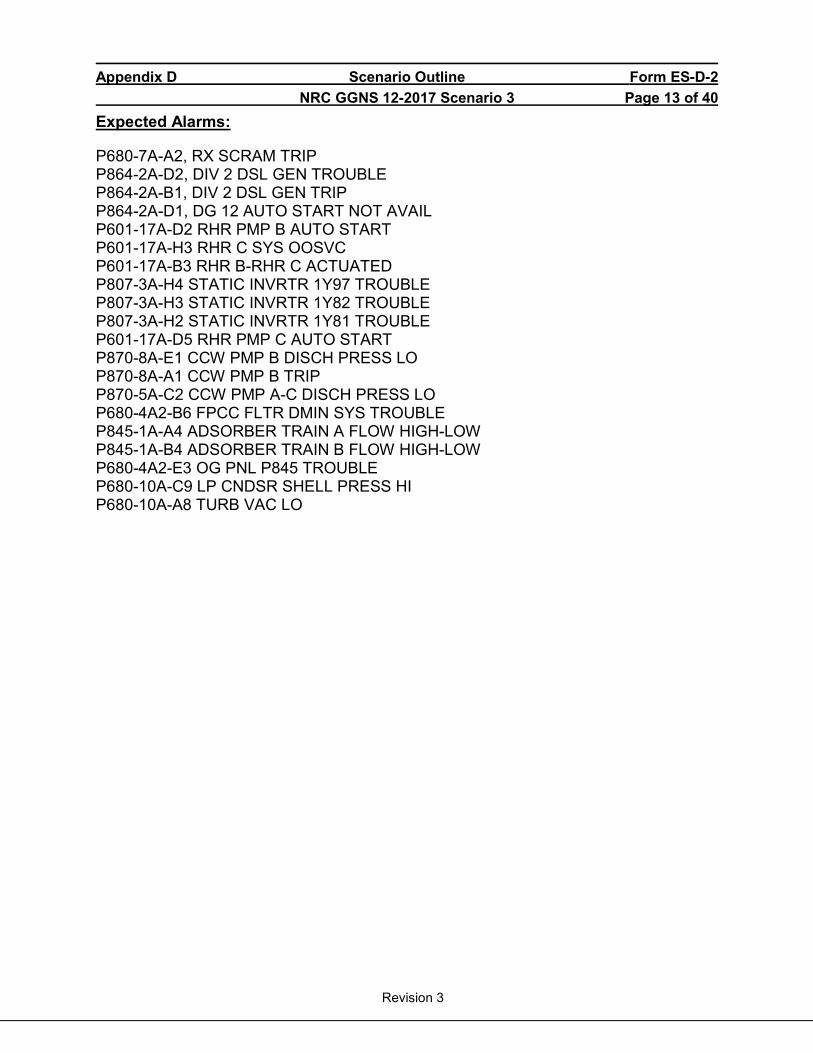
Appendix D Scenario Outline Form ES-D-2 NRC GGNS 12-2017 Scenario 3 Page 13 of 40
Revision 3
Expected Alarms:
P680-7A-A2, RX SCRAM TRIP P864-2A-D2, DIV 2 DSL GEN TROUBLE P864-2A-B1, DIV 2 DSL GEN TRIP P864-2A-D1, DG 12 AUTO START NOT AVAIL P601-17A-D2 RHR PMP B AUTO START P601-17A-H3 RHR C SYS OOSVC P601-17A-B3 RHR B-RHR C ACTUATED P807-3A-H4 STATIC INVRTR 1Y97 TROUBLE P807-3A-H3 STATIC INVRTR 1Y82 TROUBLE P807-3A-H2 STATIC INVRTR 1Y81 TROUBLE P601-17A-D5 RHR PMP C AUTO START P870-8A-E1 CCW PMP B DISCH PRESS LO P870-8A-A1 CCW PMP B TRIP P870-5A-C2 CCW PMP A-C DISCH PRESS LO P680-4A2-B6 FPCC FLTR DMIN SYS TROUBLE P845-1A-A4 ADSORBER TRAIN A FLOW HIGH-LOW P845-1A-B4 ADSORBER TRAIN B FLOW HIGH-LOW P680-4A2-E3 OG PNL P845 TROUBLE P680-10A-C9 LP CNDSR SHELL PRESS HI P680-10A-A8 TURB VAC LO
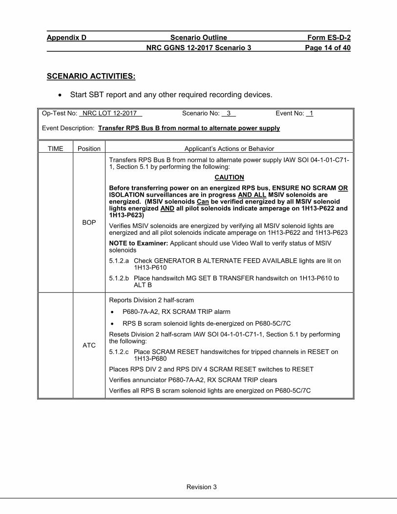
Appendix D Scenario Outline Form ES-D-2 NRC GGNS 12-2017 Scenario 3 Page 14 of 40
Revision 3
SCENARIO ACTIVITIES:
• Start SBT report and any other required recording devices.
Op-Test No: NRC LOT 12-2017 Scenario No: 3 Event No: 1 Event Description: Transfer RPS Bus B from normal to alternate power supply
TIME Position Applicant’s Actions or Behavior
BOP
Transfers RPS Bus B from normal to alternate power supply IAW SOI 04-1-01-C71-1, Section 5.1 by performing the following:
CAUTION Before transferring power on an energized RPS bus, ENSURE NO SCRAM OR ISOLATION surveillances are in progress AND ALL MSIV solenoids are energized. (MSIV solenoids Can be verified energized by all MSIV solenoid lights energized AND all pilot solenoids indicate amperage on 1H13-P622 and 1H13-P623) Verifies MSIV solenoids are energized by verifying all MSIV solenoid lights are energized and all pilot solenoids indicate amperage on 1H13-P622 and 1H13-P623 NOTE to Examiner: Applicant should use Video Wall to verify status of MSIV solenoids 5.1.2.a Check GENERATOR B ALTERNATE FEED AVAILABLE lights are lit on
1H13-P610 5.1.2.b Place handswitch MG SET B TRANSFER handswitch on 1H13-P610 to
ALT B
ATC
Reports Division 2 half-scram
• P680-7A-A2, RX SCRAM TRIP alarm
• RPS B scram solenoid lights de-energized on P680-5C/7C
Resets Division 2 half-scram IAW SOI 04-1-01-C71-1, Section 5.1 by performing the following: 5.1.2.c Place SCRAM RESET handswitches for tripped channels in RESET on
1H13-P680 Places RPS DIV 2 and RPS DIV 4 SCRAM RESET switches to RESET Verifies annunciator P680-7A-A2, RX SCRAM TRIP clears Verifies all RPS B scram solenoid lights are energized on P680-5C/7C
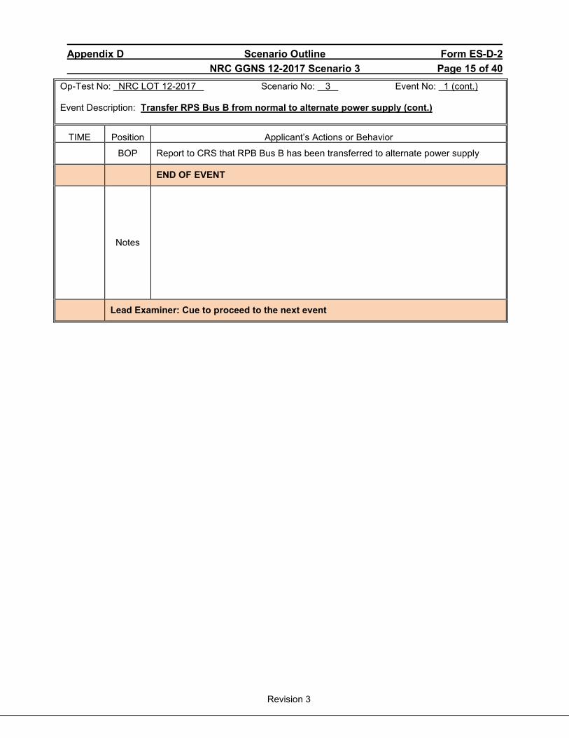
Appendix D Scenario Outline Form ES-D-2 NRC GGNS 12-2017 Scenario 3 Page 15 of 40
Revision 3
Op-Test No: NRC LOT 12-2017 Scenario No: 3 Event No: 1 (cont.) Event Description: Transfer RPS Bus B from normal to alternate power supply (cont.)
TIME Position Applicant’s Actions or Behavior
BOP Report to CRS that RPB Bus B has been transferred to alternate power supply
END OF EVENT
Notes
Lead Examiner: Cue to proceed to the next event

Appendix D Scenario Outline Form ES-D-2 NRC GGNS 12-2017 Scenario 3 Page 16 of 40
Revision 3
Op-Test No: NRC LOT 12-2017 Scenario No: 3 Event No: 2 Event Description: Division 2 Diesel Generator lube oil leak
At the direction of the Lead Evaluator, trigger Event 2 to cause a Division 2 Diesel Generator Trouble annunciator.
TIME Position Applicant’s Actions or Behavior
BOP
Responds to alarm P864-2A-D2, DIV 2 DSL GEN TROUBLE Dispatch plant operator to investigate Division 2 Diesel Generator trouble alarm
BOOTH
Role Play: If asked to investigate, wait 2 minutes and report as plant operator that oil is spraying out of a break in the discharge of the Lube Oil Circulation Pump. The pump has been secured, but oil is still draining out the pipe Report that annunciator P401-1A-B2, LOW LEVEL LUBE TANK is in alarm and lube oil tank level indication on P401 is approximately 1/8 If asked level of oil in tank, report level is approximately 20” below the top of the sump fill hole If asked amount of oil in tank, report that according to ARI, there is less than 350 gallons of oil in tank
BOP
Determine amount of oil in Division 2 Diesel Generator Lube Oil Tank is less than 350 gallons using ARI 04-1-02-1H22-P401-1A-B2, LOW LEVEL LUBE TANK Report to CRS that per ARI Tech Spec 3.8.3 should be entered
CRS
Direct BOP to place Division 2 Diesel Generator in MAINTENANCE mode IAW 04-1-01-P75-1, Standby Diesel Generator System, Attachment VI NOTE to Evaluators: If Division 2 Diesel Generator is not placed in MAINTENANCE mode, the diesel generator will auto start on the next event and will trip after 2 minutes.
CRS TS
Enters LCO 3.8.3, Diesel Fuel Oil, Lube Oil, and Starting Air: Condition B: One or more DGs with lube oil inventory:
1. For DG 11 or 12, < 410 gal and > 350 gal
• B.1 Restore lube oil inventory to within limits (48 hours) Condition E: Required Actions and associated Completion Time not met. • E.1 Declare associated DG inoperable (immediately)
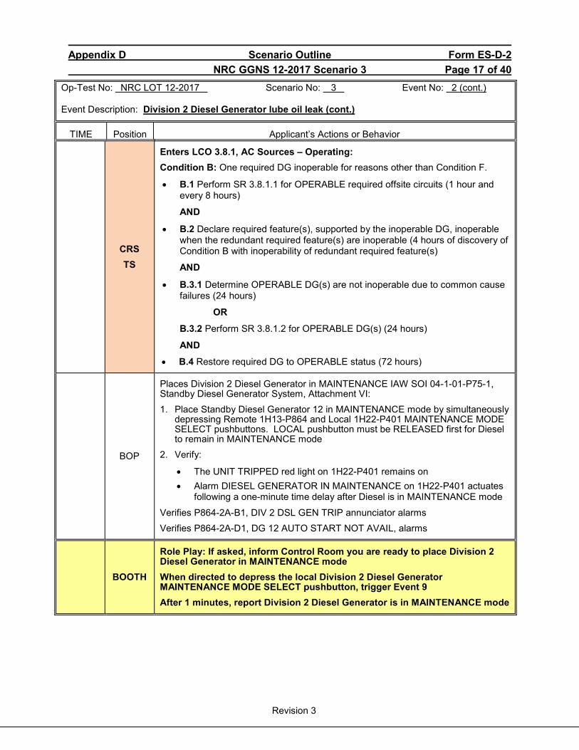
Appendix D Scenario Outline Form ES-D-2 NRC GGNS 12-2017 Scenario 3 Page 17 of 40
Revision 3
Op-Test No: NRC LOT 12-2017 Scenario No: 3 Event No: 2 (cont.) Event Description: Division 2 Diesel Generator lube oil leak (cont.)
TIME Position Applicant’s Actions or Behavior
CRS TS
Enters LCO 3.8.1, AC Sources – Operating: Condition B: One required DG inoperable for reasons other than Condition F.
• B.1 Perform SR 3.8.1.1 for OPERABLE required offsite circuits (1 hour and every 8 hours)
AND
• B.2 Declare required feature(s), supported by the inoperable DG, inoperable when the redundant required feature(s) are inoperable (4 hours of discovery of Condition B with inoperability of redundant required feature(s)
AND
• B.3.1 Determine OPERABLE DG(s) are not inoperable due to common cause failures (24 hours)
OR
B.3.2 Perform SR 3.8.1.2 for OPERABLE DG(s) (24 hours)
AND
• B.4 Restore required DG to OPERABLE status (72 hours)
BOP
Places Division 2 Diesel Generator in MAINTENANCE IAW SOI 04-1-01-P75-1, Standby Diesel Generator System, Attachment VI: 1. Place Standby Diesel Generator 12 in MAINTENANCE mode by simultaneously
depressing Remote 1H13-P864 and Local 1H22-P401 MAINTENANCE MODE SELECT pushbuttons. LOCAL pushbutton must be RELEASED first for Diesel to remain in MAINTENANCE mode
2. Verify:
• The UNIT TRIPPED red light on 1H22-P401 remains on • Alarm DIESEL GENERATOR IN MAINTENANCE on 1H22-P401 actuates
following a one-minute time delay after Diesel is in MAINTENANCE mode
Verifies P864-2A-B1, DIV 2 DSL GEN TRIP annunciator alarms Verifies P864-2A-D1, DG 12 AUTO START NOT AVAIL, alarms
BOOTH
Role Play: If asked, inform Control Room you are ready to place Division 2 Diesel Generator in MAINTENANCE mode When directed to depress the local Division 2 Diesel Generator MAINTENANCE MODE SELECT pushbutton, trigger Event 9 After 1 minutes, report Division 2 Diesel Generator is in MAINTENANCE mode
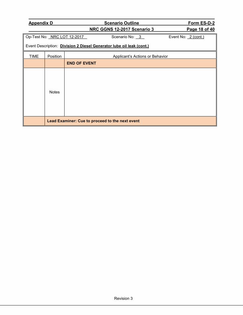
Appendix D Scenario Outline Form ES-D-2 NRC GGNS 12-2017 Scenario 3 Page 18 of 40
Revision 3
Op-Test No: NRC LOT 12-2017 Scenario No: 3 Event No: 2 (cont.) Event Description: Division 2 Diesel Generator lube oil leak (cont.)
TIME Position Applicant’s Actions or Behavior
END OF EVENT
Notes
Lead Examiner: Cue to proceed to the next event
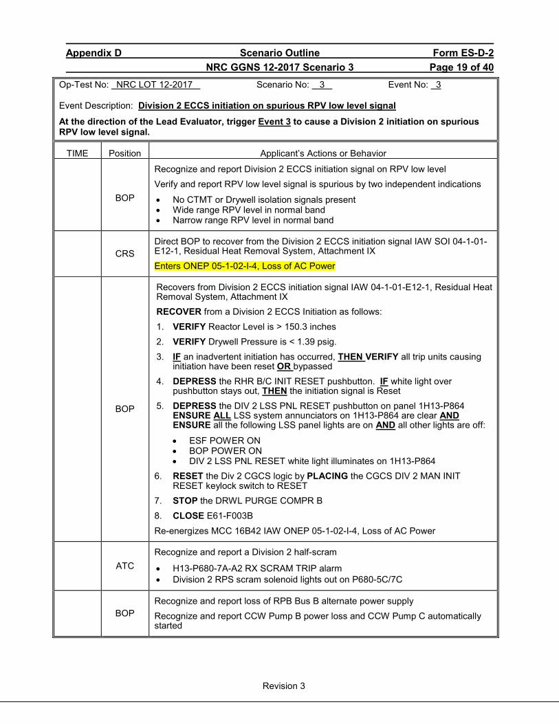
Appendix D Scenario Outline Form ES-D-2 NRC GGNS 12-2017 Scenario 3 Page 19 of 40
Revision 3
Op-Test No: NRC LOT 12-2017 Scenario No: 3 Event No: 3 Event Description: Division 2 ECCS initiation on spurious RPV low level signal
At the direction of the Lead Evaluator, trigger Event 3 to cause a Division 2 initiation on spurious RPV low level signal.
TIME Position Applicant’s Actions or Behavior
BOP
Recognize and report Division 2 ECCS initiation signal on RPV low level Verify and report RPV low level signal is spurious by two independent indications
• No CTMT or Drywell isolation signals present • Wide range RPV level in normal band • Narrow range RPV level in normal band
CRS
Direct BOP to recover from the Division 2 ECCS initiation signal IAW SOI 04-1-01-E12-1, Residual Heat Removal System, Attachment IX Enters ONEP 05-1-02-I-4, Loss of AC Power
BOP
Recovers from Division 2 ECCS initiation signal IAW 04-1-01-E12-1, Residual Heat Removal System, Attachment IX RECOVER from a Division 2 ECCS Initiation as follows: 1. VERIFY Reactor Level is > 150.3 inches 2. VERIFY Drywell Pressure is < 1.39 psig. 3. IF an inadvertent initiation has occurred, THEN VERIFY all trip units causing
initiation have been reset OR bypassed 4. DEPRESS the RHR B/C INIT RESET pushbutton. IF white light over
pushbutton stays out, THEN the initiation signal is Reset 5. DEPRESS the DIV 2 LSS PNL RESET pushbutton on panel 1H13-P864
ENSURE ALL LSS system annunciators on 1H13-P864 are clear AND ENSURE all the following LSS panel lights are on AND all other lights are off:
• ESF POWER ON • BOP POWER ON • DIV 2 LSS PNL RESET white light illuminates on 1H13-P864
6. RESET the Div 2 CGCS logic by PLACING the CGCS DIV 2 MAN INIT RESET keylock switch to RESET
7. STOP the DRWL PURGE COMPR B 8. CLOSE E61-F003B Re-energizes MCC 16B42 IAW ONEP 05-1-02-I-4, Loss of AC Power
ATC
Recognize and report a Division 2 half-scram
• H13-P680-7A-A2 RX SCRAM TRIP alarm • Division 2 RPS scram solenoid lights out on P680-5C/7C
BOP
Recognize and report loss of RPB Bus B alternate power supply Recognize and report CCW Pump B power loss and CCW Pump C automatically started
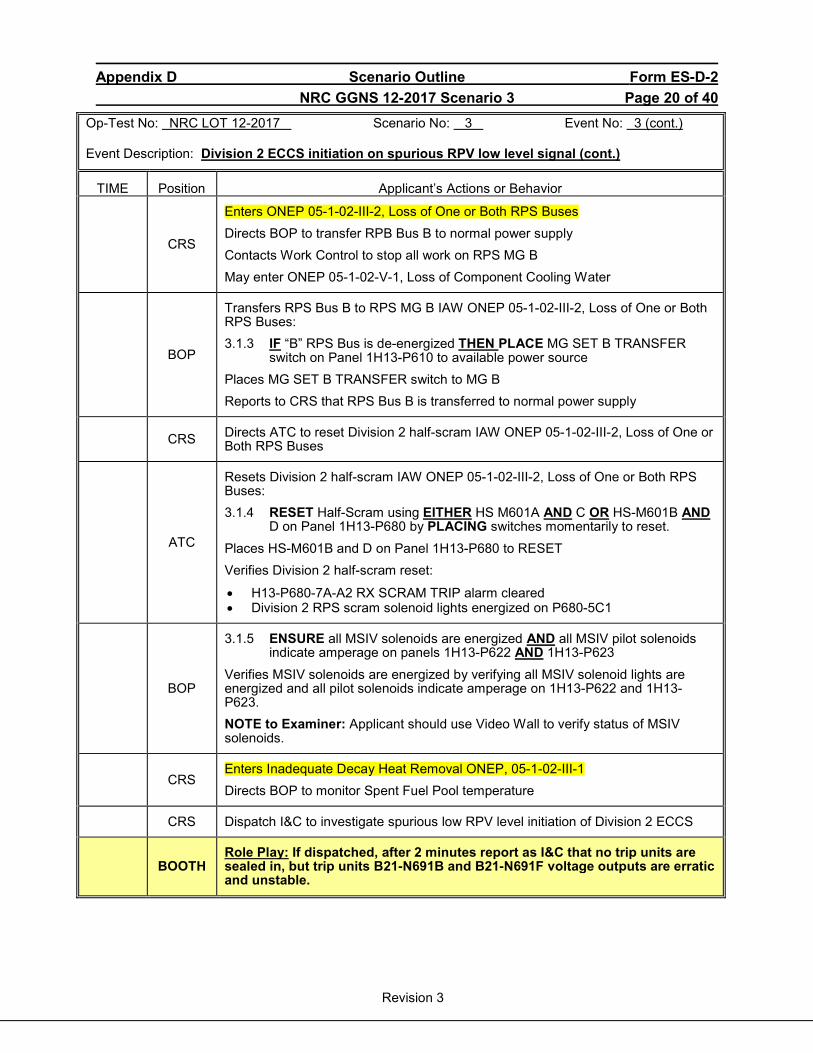
Appendix D Scenario Outline Form ES-D-2 NRC GGNS 12-2017 Scenario 3 Page 20 of 40
Revision 3
Op-Test No: NRC LOT 12-2017 Scenario No: 3 Event No: 3 (cont.) Event Description: Division 2 ECCS initiation on spurious RPV low level signal (cont.)
TIME Position Applicant’s Actions or Behavior
CRS
Enters ONEP 05-1-02-III-2, Loss of One or Both RPS Buses Directs BOP to transfer RPB Bus B to normal power supply Contacts Work Control to stop all work on RPS MG B May enter ONEP 05-1-02-V-1, Loss of Component Cooling Water
BOP
Transfers RPS Bus B to RPS MG B IAW ONEP 05-1-02-III-2, Loss of One or Both RPS Buses: 3.1.3 IF “B” RPS Bus is de-energized THEN PLACE MG SET B TRANSFER
switch on Panel 1H13-P610 to available power source Places MG SET B TRANSFER switch to MG B Reports to CRS that RPS Bus B is transferred to normal power supply
CRS Directs ATC to reset Division 2 half-scram IAW ONEP 05-1-02-III-2, Loss of One or Both RPS Buses
ATC
Resets Division 2 half-scram IAW ONEP 05-1-02-III-2, Loss of One or Both RPS Buses: 3.1.4 RESET Half-Scram using EITHER HS M601A AND C OR HS-M601B AND
D on Panel 1H13-P680 by PLACING switches momentarily to reset. Places HS-M601B and D on Panel 1H13-P680 to RESET Verifies Division 2 half-scram reset:
• H13-P680-7A-A2 RX SCRAM TRIP alarm cleared • Division 2 RPS scram solenoid lights energized on P680-5C1
BOP
3.1.5 ENSURE all MSIV solenoids are energized AND all MSIV pilot solenoids indicate amperage on panels 1H13-P622 AND 1H13-P623
Verifies MSIV solenoids are energized by verifying all MSIV solenoid lights are energized and all pilot solenoids indicate amperage on 1H13-P622 and 1H13-P623. NOTE to Examiner: Applicant should use Video Wall to verify status of MSIV solenoids.
CRS Enters Inadequate Decay Heat Removal ONEP, 05-1-02-III-1 Directs BOP to monitor Spent Fuel Pool temperature
CRS Dispatch I&C to investigate spurious low RPV level initiation of Division 2 ECCS
BOOTH Role Play: If dispatched, after 2 minutes report as I&C that no trip units are sealed in, but trip units B21-N691B and B21-N691F voltage outputs are erratic and unstable.
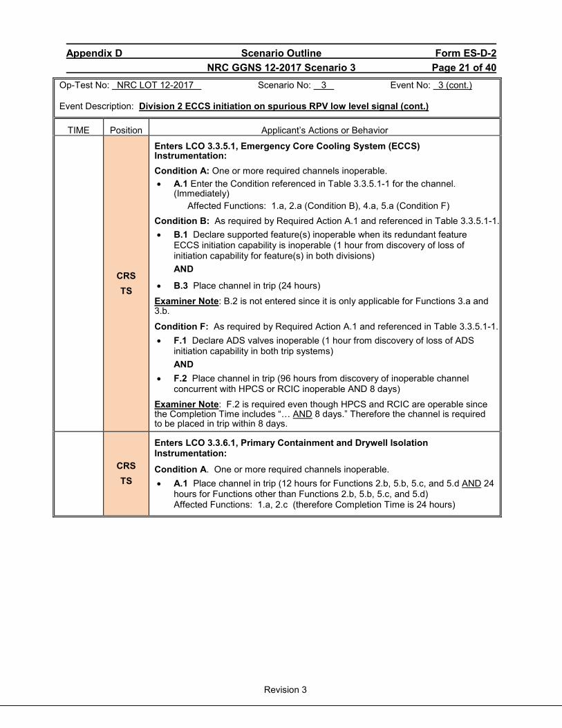
Appendix D Scenario Outline Form ES-D-2 NRC GGNS 12-2017 Scenario 3 Page 21 of 40
Revision 3
Op-Test No: NRC LOT 12-2017 Scenario No: 3 Event No: 3 (cont.) Event Description: Division 2 ECCS initiation on spurious RPV low level signal (cont.)
TIME Position Applicant’s Actions or Behavior
CRS TS
Enters LCO 3.3.5.1, Emergency Core Cooling System (ECCS) Instrumentation: Condition A: One or more required channels inoperable. • A.1 Enter the Condition referenced in Table 3.3.5.1-1 for the channel.
(Immediately) Affected Functions: 1.a, 2.a (Condition B), 4.a, 5.a (Condition F) Condition B: As required by Required Action A.1 and referenced in Table 3.3.5.1-1. • B.1 Declare supported feature(s) inoperable when its redundant feature
ECCS initiation capability is inoperable (1 hour from discovery of loss of initiation capability for feature(s) in both divisions) AND
• B.3 Place channel in trip (24 hours)
Examiner Note: B.2 is not entered since it is only applicable for Functions 3.a and 3.b.
Condition F: As required by Required Action A.1 and referenced in Table 3.3.5.1-1. • F.1 Declare ADS valves inoperable (1 hour from discovery of loss of ADS
initiation capability in both trip systems) AND
• F.2 Place channel in trip (96 hours from discovery of inoperable channel concurrent with HPCS or RCIC inoperable AND 8 days)
Examiner Note: F.2 is required even though HPCS and RCIC are operable since the Completion Time includes “… AND 8 days.” Therefore the channel is required to be placed in trip within 8 days.
CRS TS
Enters LCO 3.3.6.1, Primary Containment and Drywell Isolation Instrumentation:
Condition A. One or more required channels inoperable. • A.1 Place channel in trip (12 hours for Functions 2.b, 5.b, 5.c, and 5.d AND 24
hours for Functions other than Functions 2.b, 5.b, 5.c, and 5.d) Affected Functions: 1.a, 2.c (therefore Completion Time is 24 hours)

Appendix D Scenario Outline Form ES-D-2 NRC GGNS 12-2017 Scenario 3 Page 22 of 40
Revision 3
Op-Test No: NRC LOT 12-2017 Scenario No: 3 Event No: 3 (cont.) Event Description: Division 2 ECCS initiation on spurious RPV low level signal (cont.)
TIME Position Applicant’s Actions or Behavior
CRS TS
Enters LCO 3.3.6.3, RHR Containment Spray System Instrumentation: Condition A: One or more required channels inoperable. • A.1 Enter the Condition referenced in Table 3.3.6.3-1 for the channel.
(Immediately) Affected Function: 3 (Condition B)
Condition B: As required by Required Action A.1 and referenced in Table 3.3.6.3-1. • B.1 Declare associated RHR containment spray subsystem inoperable (1
hour from discovery of loss of RHR containment spray initiation capability in both trip systems AND
• B.2 Place channel in trip (24 hours)
CRS TS
Enters LCO 3.3.6.4, Suppression Pool Makeup (SPMU) System Instrumentation:
Condition A: One or more required channels inoperable. • A.1 Enter the Condition referenced in Table 3.3.6.4-1 for the channel.
(Immediately) Affected Function: 2 (Condition B)
Condition B: As required by Required Action A.1 and referenced in Table 3.3.6.4-1. • B.1 Declare associated SPMU subsystem inoperable (1 hour of discovery of
loss of SPMU initiation capability in both trip systems AND
• B.2 Place channel in trip (24 hours)
END OF EVENT
Notes
Lead Examiner: Cue to proceed to the next event
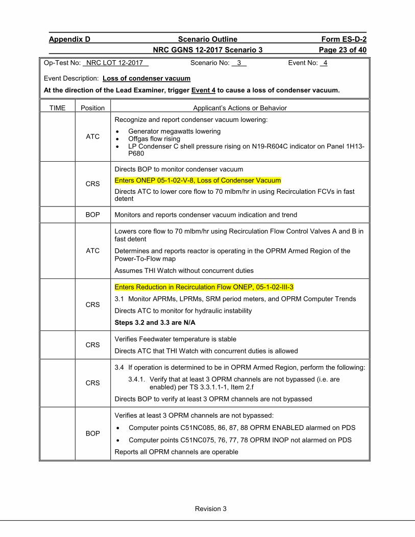
Appendix D Scenario Outline Form ES-D-2 NRC GGNS 12-2017 Scenario 3 Page 23 of 40
Revision 3
Op-Test No: NRC LOT 12-2017 Scenario No: 3 Event No: 4 Event Description: Loss of condenser vacuum
At the direction of the Lead Examiner, trigger Event 4 to cause a loss of condenser vacuum.
TIME Position Applicant’s Actions or Behavior
ATC
Recognize and report condenser vacuum lowering:
• Generator megawatts lowering • Offgas flow rising • LP Condenser C shell pressure rising on N19-R604C indicator on Panel 1H13-
P680
CRS
Directs BOP to monitor condenser vacuum Enters ONEP 05-1-02-V-8, Loss of Condenser Vacuum Directs ATC to lower core flow to 70 mlbm/hr in using Recirculation FCVs in fast detent
BOP Monitors and reports condenser vacuum indication and trend
ATC
Lowers core flow to 70 mlbm/hr using Recirculation Flow Control Valves A and B in fast detent
Determines and reports reactor is operating in the OPRM Armed Region of the Power-To-Flow map
Assumes THI Watch without concurrent duties
CRS
Enters Reduction in Recirculation Flow ONEP, 05-1-02-III-3
3.1 Monitor APRMs, LPRMs, SRM period meters, and OPRM Computer Trends
Directs ATC to monitor for hydraulic instability
Steps 3.2 and 3.3 are N/A
CRS
Verifies Feedwater temperature is stable
Directs ATC that THI Watch with concurrent duties is allowed
CRS
3.4 If operation is determined to be in OPRM Armed Region, perform the following:
3.4.1. Verify that at least 3 OPRM channels are not bypassed (i.e. are enabled) per TS 3.3.1.1-1, Item 2.f
Directs BOP to verify at least 3 OPRM channels are not bypassed
BOP
Verifies at least 3 OPRM channels are not bypassed:
• Computer points C51NC085, 86, 87, 88 OPRM ENABLED alarmed on PDS
• Computer points C51NC075, 76, 77, 78 OPRM INOP not alarmed on PDS
Reports all OPRM channels are operable
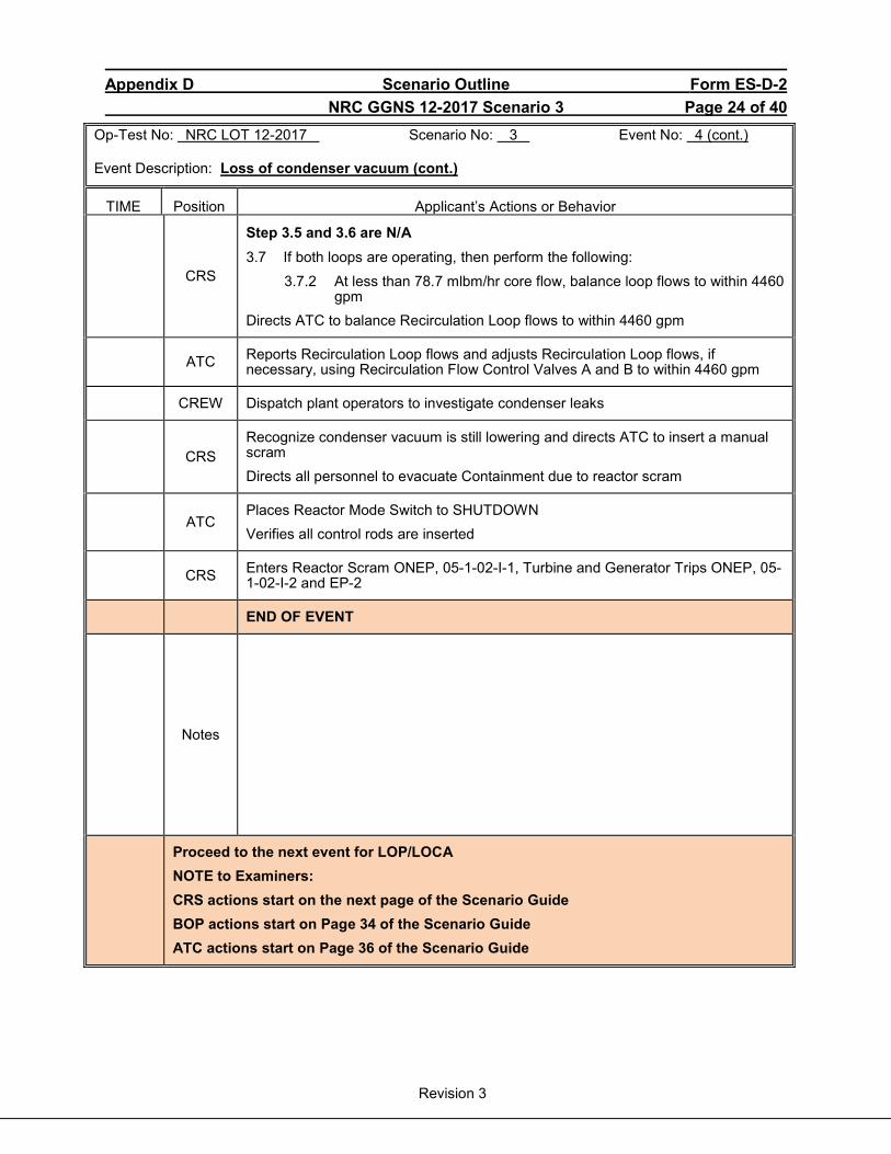
Appendix D Scenario Outline Form ES-D-2 NRC GGNS 12-2017 Scenario 3 Page 24 of 40
Revision 3
Op-Test No: NRC LOT 12-2017 Scenario No: 3 Event No: 4 (cont.) Event Description: Loss of condenser vacuum (cont.)
TIME Position Applicant’s Actions or Behavior
CRS
Step 3.5 and 3.6 are N/A
3.7 If both loops are operating, then perform the following: 3.7.2 At less than 78.7 mlbm/hr core flow, balance loop flows to within 4460
gpm Directs ATC to balance Recirculation Loop flows to within 4460 gpm
ATC Reports Recirculation Loop flows and adjusts Recirculation Loop flows, if necessary, using Recirculation Flow Control Valves A and B to within 4460 gpm
CREW Dispatch plant operators to investigate condenser leaks
CRS
Recognize condenser vacuum is still lowering and directs ATC to insert a manual scram Directs all personnel to evacuate Containment due to reactor scram
ATC
Places Reactor Mode Switch to SHUTDOWN Verifies all control rods are inserted
CRS Enters Reactor Scram ONEP, 05-1-02-I-1, Turbine and Generator Trips ONEP, 05-1-02-I-2 and EP-2
END OF EVENT
Notes
Proceed to the next event for LOP/LOCA NOTE to Examiners: CRS actions start on the next page of the Scenario Guide BOP actions start on Page 34 of the Scenario Guide ATC actions start on Page 36 of the Scenario Guide
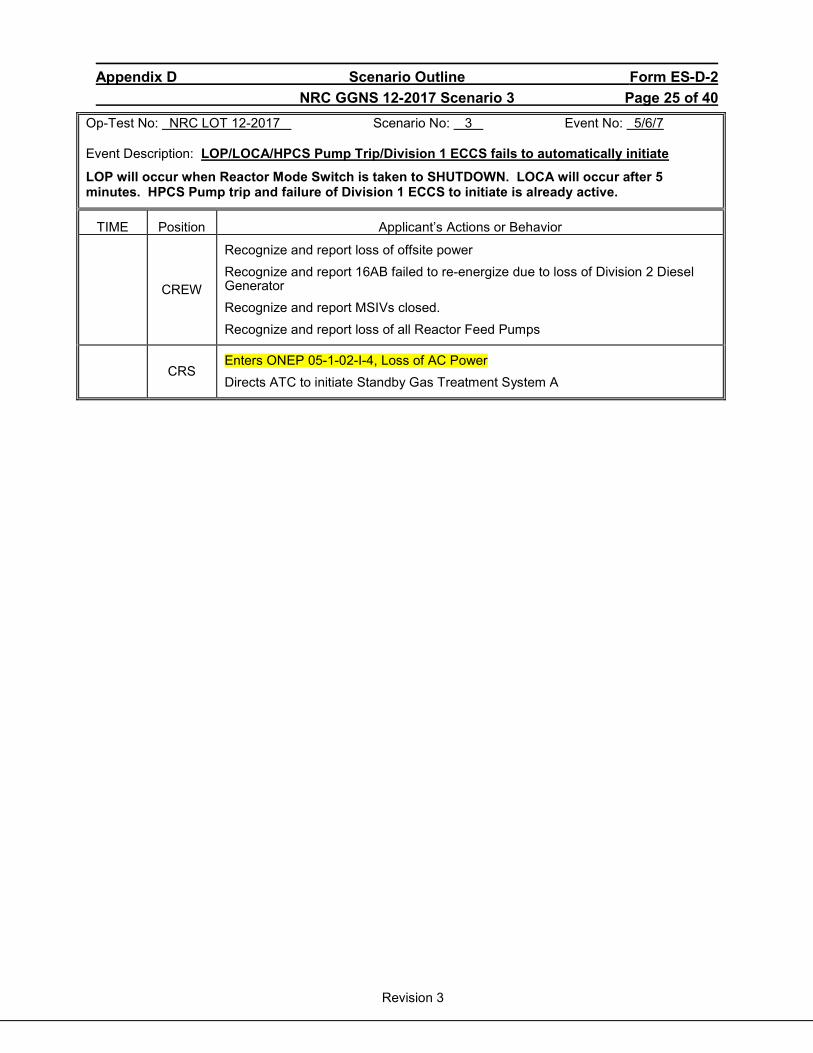
Appendix D Scenario Outline Form ES-D-2 NRC GGNS 12-2017 Scenario 3 Page 25 of 40
Revision 3
Op-Test No: NRC LOT 12-2017 Scenario No: 3 Event No: 5/6/7 Event Description: LOP/LOCA/HPCS Pump Trip/Division 1 ECCS fails to automatically initiate
LOP will occur when Reactor Mode Switch is taken to SHUTDOWN. LOCA will occur after 5 minutes. HPCS Pump trip and failure of Division 1 ECCS to initiate is already active.
TIME Position Applicant’s Actions or Behavior
CREW
Recognize and report loss of offsite power Recognize and report 16AB failed to re-energize due to loss of Division 2 Diesel Generator Recognize and report MSIVs closed. Recognize and report loss of all Reactor Feed Pumps
CRS
Enters ONEP 05-1-02-I-4, Loss of AC Power Directs ATC to initiate Standby Gas Treatment System A
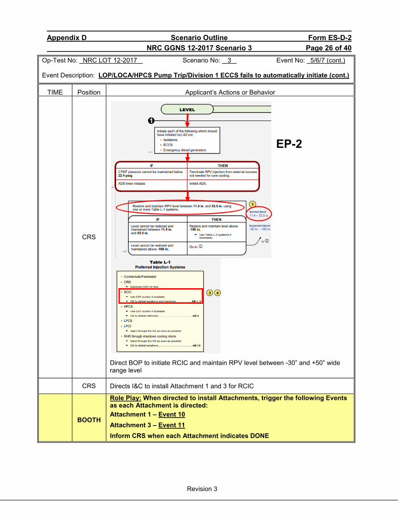
Appendix D Scenario Outline Form ES-D-2 NRC GGNS 12-2017 Scenario 3 Page 26 of 40
Revision 3
Op-Test No: NRC LOT 12-2017 Scenario No: 3 Event No: 5/6/7 (cont.) Event Description: LOP/LOCA/HPCS Pump Trip/Division 1 ECCS fails to automatically initiate (cont.)
TIME Position Applicant’s Actions or Behavior
CRS
Direct BOP to initiate RCIC and maintain RPV level between -30” and +50” wide range level
CRS Directs I&C to install Attachment 1 and 3 for RCIC
BOOTH
Role Play: When directed to install Attachments, trigger the following Events as each Attachment is directed: Attachment 1 – Event 10 Attachment 3 – Event 11 Inform CRS when each Attachment indicates DONE
EP-2
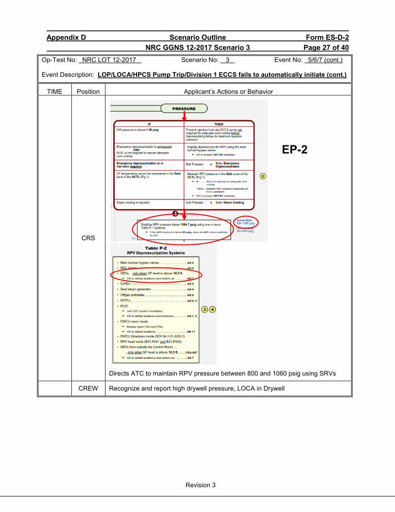
Appendix D Scenario Outline Form ES-D-2 NRC GGNS 12-2017 Scenario 3 Page 27 of 40
Revision 3
Op-Test No: NRC LOT 12-2017 Scenario No: 3 Event No: 5/6/7 (cont.) Event Description: LOP/LOCA/HPCS Pump Trip/Division 1 ECCS fails to automatically initiate (cont.)
TIME Position Applicant’s Actions or Behavior
CRS
Directs ATC to maintain RPV pressure between 800 and 1060 psig using SRVs
CREW Recognize and report high drywell pressure, LOCA in Drywell
EP-2
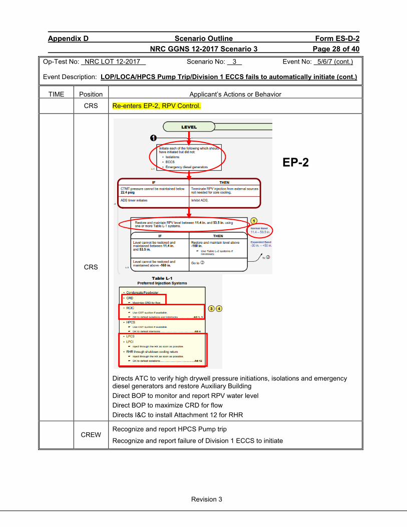
Appendix D Scenario Outline Form ES-D-2 NRC GGNS 12-2017 Scenario 3 Page 28 of 40
Revision 3
Op-Test No: NRC LOT 12-2017 Scenario No: 3 Event No: 5/6/7 (cont.) Event Description: LOP/LOCA/HPCS Pump Trip/Division 1 ECCS fails to automatically initiate (cont.)
TIME Position Applicant’s Actions or Behavior
CRS Re-enters EP-2, RPV Control.
CRS
Directs ATC to verify high drywell pressure initiations, isolations and emergency diesel generators and restore Auxiliary Building Direct BOP to monitor and report RPV water level Direct BOP to maximize CRD for flow Directs I&C to install Attachment 12 for RHR
CREW
Recognize and report HPCS Pump trip
Recognize and report failure of Division 1 ECCS to initiate
EP-2
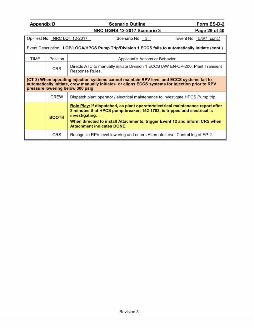
Appendix D Scenario Outline Form ES-D-2 NRC GGNS 12-2017 Scenario 3 Page 29 of 40
Revision 3
Op-Test No: NRC LOT 12-2017 Scenario No: 3 Event No: 5/6/7 (cont.) Event Description: LOP/LOCA/HPCS Pump Trip/Division 1 ECCS fails to automatically initiate (cont.)
TIME Position Applicant’s Actions or Behavior
CRS Directs ATC to manually initiate Division 1 ECCS IAW EN-OP-200, Plant Transient Response Rules.
(CT-3) When operating injection systems cannot maintain RPV level and ECCS systems fail to automatically initiate, crew manually initiates or aligns ECCS systems for injection prior to RPV pressure lowering below 300 psig
CREW Dispatch plant operator / electrical maintenance to investigate HPCS Pump trip.
BOOTH
Role Play: If dispatched, as plant operator/electrical maintenance report after 2 minutes that HPCS pump breaker, 152-1702, is tripped and electrical is investigating. When directed to install Attachments, trigger Event 12 and inform CRS when Attachment indicates DONE.
CRS Recognize RPV level lowering and enters Alternate Level Control leg of EP-2.

Appendix D Scenario Outline Form ES-D-2 NRC GGNS 12-2017 Scenario 3 Page 30 of 40
Revision 3
Op-Test No: NRC LOT 12-2017 Scenario No: 3 Event No: 5/6/7 (cont.) Event Description: LOP/LOCA/HPCS Pump Trip/Division 1 ECCS fails to automatically initiate (cont.)
TIME Position Applicant’s Actions or Behavior
CRS
Direct ATC to inhibit ADS
Direct ATC to initiate SLC A
Direct BOP to verify LPCS and RHR A are available for injection
(CT-1) Inhibit ADS prior to automatic ADS valve opening during a LOCA
EP-2

Appendix D Scenario Outline Form ES-D-2 NRC GGNS 12-2017 Scenario 3 Page 31 of 40
Revision 3
Op-Test No: NRC LOT 12-2017 Scenario No: 3 Event No: 5/6/7 (cont.) Event Description: LOP/LOCA/HPCS Pump Trip/Division 1 ECCS fails to automatically initiate (cont.)
TIME Position Applicant’s Actions or Behavior
CRS Enters EP-3, Containment Control
CRS
Monitors HCTL on SPDS May direct ATC to initiate Division 1 Suppression Pool Makeup System
CRS
Directs ATC to verify CTMT and DW hydrogen analyzers operating and energize Division 1 igniters
EP-3
EP-3
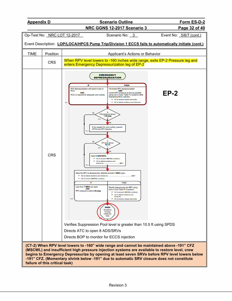
Appendix D Scenario Outline Form ES-D-2 NRC GGNS 12-2017 Scenario 3 Page 32 of 40
Revision 3
Op-Test No: NRC LOT 12-2017 Scenario No: 3 Event No: 5/6/7 (cont.) Event Description: LOP/LOCA/HPCS Pump Trip/Division 1 ECCS fails to automatically initiate (cont.)
TIME Position Applicant’s Actions or Behavior
CRS When RPV level lowers to -160 inches wide range, exits EP-2 Pressure leg and enters Emergency Depressurization leg of EP-2
CRS
Verifies Suppression Pool level is greater than 10.5 ft using SPDS Directs ATC to open 8 ADS/SRVs Directs BOP to monitor for ECCS injection
(CT-2) When RPV level lowers to -160” wide range and cannot be maintained above -191” CFZ (MSCWL) and insufficient high pressure injection systems are available to restore level, crew begins to Emergency Depressurize by opening at least seven SRVs before RPV level lowers below -191” CFZ. (Momentary shrink below -191” due to automatic SRV closure does not constitute failure of this critical task)
EP-2
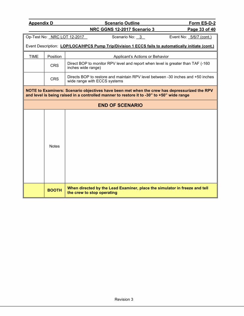
Appendix D Scenario Outline Form ES-D-2 NRC GGNS 12-2017 Scenario 3 Page 33 of 40
Revision 3
Op-Test No: NRC LOT 12-2017 Scenario No: 3 Event No: 5/6/7 (cont.) Event Description: LOP/LOCA/HPCS Pump Trip/Division 1 ECCS fails to automatically initiate (cont.)
TIME Position Applicant’s Actions or Behavior
CRS Direct BOP to monitor RPV level and report when level is greater than TAF (-160 inches wide range)
CRS Directs BOP to restore and maintain RPV level between -30 inches and +50 inches wide range with ECCS systems
NOTE to Examiners: Scenario objectives have been met when the crew has depressurized the RPV and level is being raised in a controlled manner to restore it to -30” to +50” wide range
END OF SCENARIO
Notes
BOOTH When directed by the Lead Examiner, place the simulator in freeze and tell the crew to stop operating
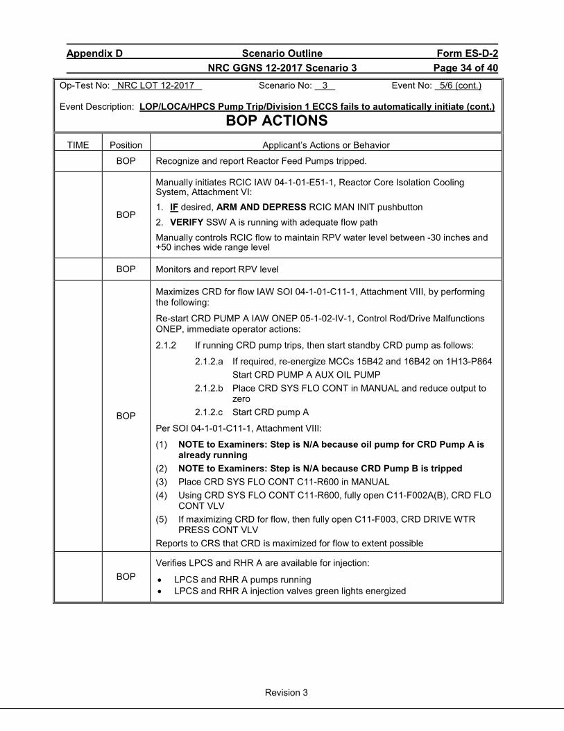
Appendix D Scenario Outline Form ES-D-2 NRC GGNS 12-2017 Scenario 3 Page 34 of 40
Revision 3
Op-Test No: NRC LOT 12-2017 Scenario No: 3 Event No: 5/6 (cont.) Event Description: LOP/LOCA/HPCS Pump Trip/Division 1 ECCS fails to automatically initiate (cont.) BOP ACTIONS
TIME Position Applicant’s Actions or Behavior
BOP Recognize and report Reactor Feed Pumps tripped.
BOP
Manually initiates RCIC IAW 04-1-01-E51-1, Reactor Core Isolation Cooling System, Attachment VI: 1. IF desired, ARM AND DEPRESS RCIC MAN INIT pushbutton 2. VERIFY SSW A is running with adequate flow path Manually controls RCIC flow to maintain RPV water level between -30 inches and +50 inches wide range level
BOP Monitors and report RPV level
BOP
Maximizes CRD for flow IAW SOI 04-1-01-C11-1, Attachment VIII, by performing the following:
Re-start CRD PUMP A IAW ONEP 05-1-02-IV-1, Control Rod/Drive Malfunctions ONEP, immediate operator actions:
2.1.2 If running CRD pump trips, then start standby CRD pump as follows:
2.1.2.a If required, re-energize MCCs 15B42 and 16B42 on 1H13-P864 Start CRD PUMP A AUX OIL PUMP 2.1.2.b Place CRD SYS FLO CONT in MANUAL and reduce output to
zero 2.1.2.c Start CRD pump A
Per SOI 04-1-01-C11-1, Attachment VIII:
(1) NOTE to Examiners: Step is N/A because oil pump for CRD Pump A is already running
(2) NOTE to Examiners: Step is N/A because CRD Pump B is tripped (3) Place CRD SYS FLO CONT C11-R600 in MANUAL (4) Using CRD SYS FLO CONT C11-R600, fully open C11-F002A(B), CRD FLO
CONT VLV (5) If maximizing CRD for flow, then fully open C11-F003, CRD DRIVE WTR
PRESS CONT VLV Reports to CRS that CRD is maximized for flow to extent possible
BOP
Verifies LPCS and RHR A are available for injection:
• LPCS and RHR A pumps running • LPCS and RHR A injection valves green lights energized
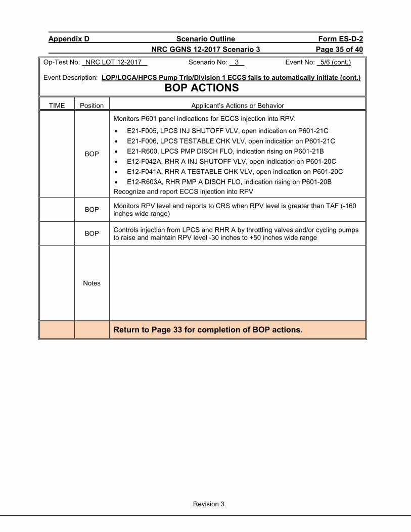
Appendix D Scenario Outline Form ES-D-2 NRC GGNS 12-2017 Scenario 3 Page 35 of 40
Revision 3
Op-Test No: NRC LOT 12-2017 Scenario No: 3 Event No: 5/6 (cont.) Event Description: LOP/LOCA/HPCS Pump Trip/Division 1 ECCS fails to automatically initiate (cont.) BOP ACTIONS
TIME Position Applicant’s Actions or Behavior
BOP
Monitors P601 panel indications for ECCS injection into RPV:
• E21-F005, LPCS INJ SHUTOFF VLV, open indication on P601-21C • E21-F006, LPCS TESTABLE CHK VLV, open indication on P601-21C • E21-R600, LPCS PMP DISCH FLO, indication rising on P601-21B • E12-F042A, RHR A INJ SHUTOFF VLV, open indication on P601-20C • E12-F041A, RHR A TESTABLE CHK VLV, open indication on P601-20C • E12-R603A, RHR PMP A DISCH FLO, indication rising on P601-20B Recognize and report ECCS injection into RPV
BOP Monitors RPV level and reports to CRS when RPV level is greater than TAF (-160 inches wide range)
BOP Controls injection from LPCS and RHR A by throttling valves and/or cycling pumps to raise and maintain RPV level -30 inches to +50 inches wide range
Notes
Return to Page 33 for completion of BOP actions.
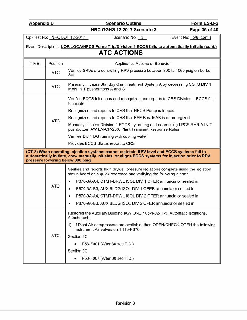
Appendix D Scenario Outline Form ES-D-2 NRC GGNS 12-2017 Scenario 3 Page 36 of 40
Revision 3
Op-Test No: NRC LOT 12-2017 Scenario No: 3 Event No: 5/6 (cont.) Event Description: LOP/LOCA/HPCS Pump Trip/Division 1 ECCS fails to automatically initiate (cont.) ATC ACTIONS
TIME Position Applicant’s Actions or Behavior
ATC Verifies SRVs are controlling RPV pressure between 800 to 1060 psig on Lo-Lo Set
ATC Manually initiates Standby Gas Treatment System A by depressing SGTS DIV 1 MAN INIT pushbuttons A and C
ATC
Verifies ECCS initiations and recognizes and reports to CRS Division 1 ECCS fails to initiate
Recognizes and reports to CRS that HPCS Pump is tripped
Recognizes and reports to CRS that ESF Bus 16AB is de-energized
Manually initiates Division 1 ECCS by arming and depressing LPCS/RHR A INIT pushbutton IAW EN-OP-200, Plant Transient Response Rules
Verifies Div 1 DG running with cooling water
Provides ECCS Status report to CRS
(CT-3) When operating injection systems cannot maintain RPV level and ECCS systems fail to automatically initiate, crew manually initiates or aligns ECCS systems for injection prior to RPV pressure lowering below 300 psig
ATC
Verifies and reports high drywell pressure isolations complete using the isolation status board as a quick reference and verifying the following alarms:
• P870-3A-A4, CTMT-DRWL ISOL DIV 1 OPER annunciator sealed in
• P870-3A-B3, AUX BLDG ISOL DIV 1 OPER annunciator sealed in
• P870-9A-A4, CTMT-DRWL ISOL DIV 2 OPER annunciator sealed in
• P870-9A-B3, AUX BLDG ISOL DIV 2 OPER annunciator sealed in
ATC
Restores the Auxiliary Building IAW ONEP 05-1-02-III-5, Automatic Isolations, Attachment II
1) If Plant Air compressors are available, then OPEN/CHECK OPEN the following Instrument Air valves on 1H13-P870:
Section 3C
• P53-F001 (After 30 sec T.D.)
Section 9C
• P53-F007 (After 30 sec T.D.)
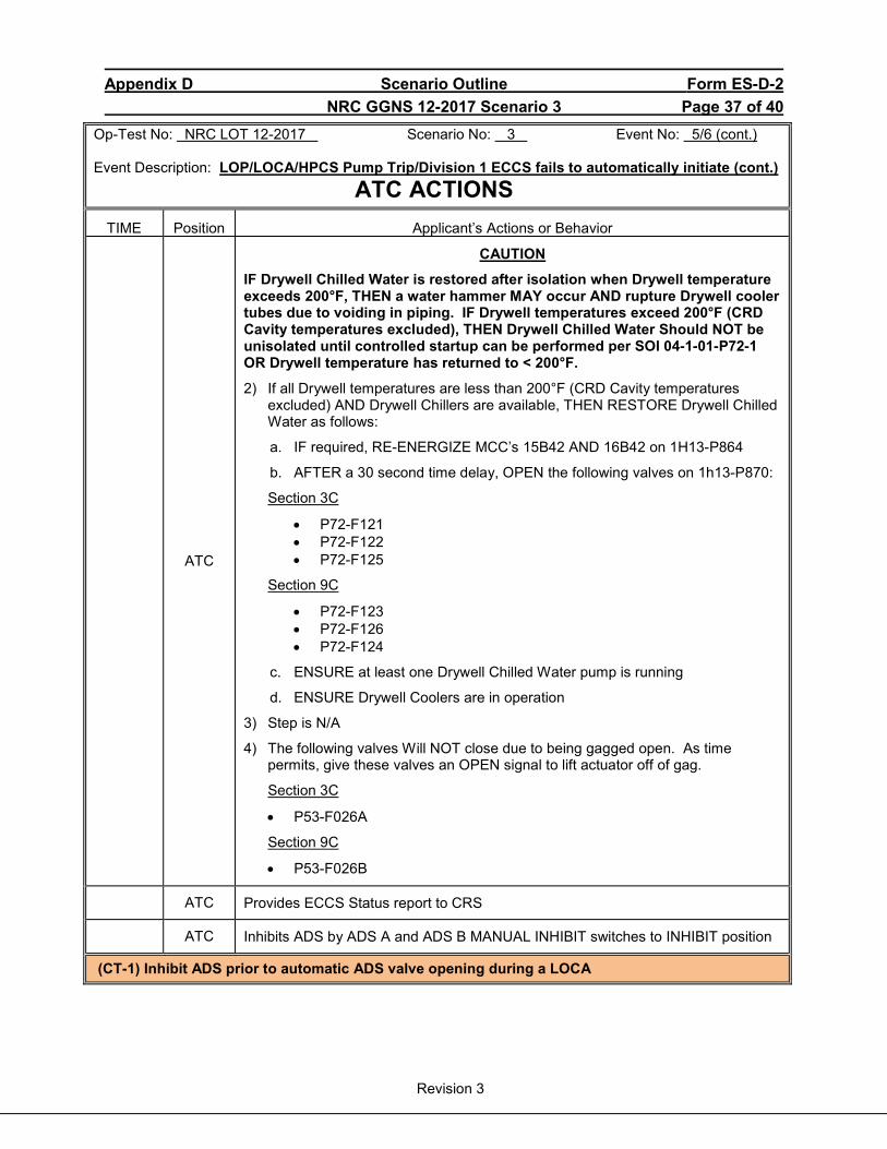
Appendix D Scenario Outline Form ES-D-2 NRC GGNS 12-2017 Scenario 3 Page 37 of 40
Revision 3
Op-Test No: NRC LOT 12-2017 Scenario No: 3 Event No: 5/6 (cont.) Event Description: LOP/LOCA/HPCS Pump Trip/Division 1 ECCS fails to automatically initiate (cont.) ATC ACTIONS
TIME Position Applicant’s Actions or Behavior
ATC
CAUTION
IF Drywell Chilled Water is restored after isolation when Drywell temperature exceeds 200°F, THEN a water hammer MAY occur AND rupture Drywell cooler tubes due to voiding in piping. IF Drywell temperatures exceed 200°F (CRD Cavity temperatures excluded), THEN Drywell Chilled Water Should NOT be unisolated until controlled startup can be performed per SOI 04-1-01-P72-1 OR Drywell temperature has returned to < 200°F.
2) If all Drywell temperatures are less than 200°F (CRD Cavity temperatures excluded) AND Drywell Chillers are available, THEN RESTORE Drywell Chilled Water as follows:
a. IF required, RE-ENERGIZE MCC’s 15B42 AND 16B42 on 1H13-P864
b. AFTER a 30 second time delay, OPEN the following valves on 1h13-P870:
Section 3C
• P72-F121 • P72-F122 • P72-F125
Section 9C
• P72-F123 • P72-F126 • P72-F124
c. ENSURE at least one Drywell Chilled Water pump is running
d. ENSURE Drywell Coolers are in operation
3) Step is N/A
4) The following valves Will NOT close due to being gagged open. As time permits, give these valves an OPEN signal to lift actuator off of gag.
Section 3C
• P53-F026A
Section 9C
• P53-F026B
ATC Provides ECCS Status report to CRS
ATC Inhibits ADS by ADS A and ADS B MANUAL INHIBIT switches to INHIBIT position
(CT-1) Inhibit ADS prior to automatic ADS valve opening during a LOCA
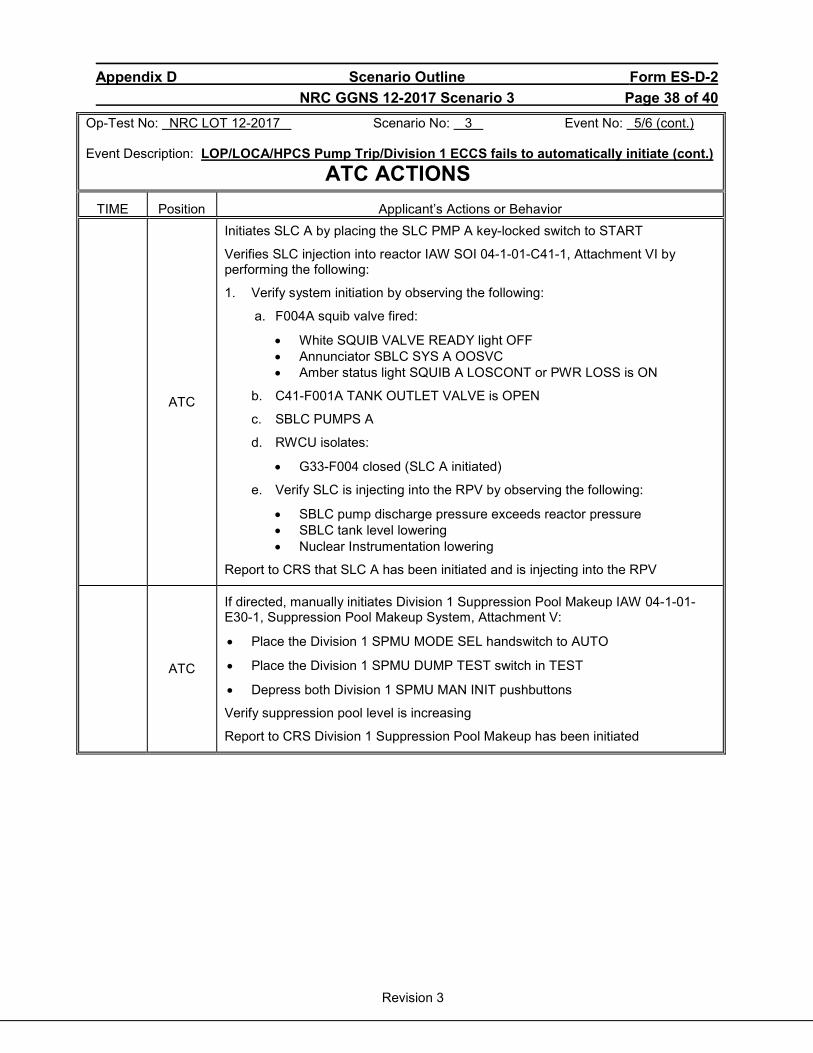
Appendix D Scenario Outline Form ES-D-2 NRC GGNS 12-2017 Scenario 3 Page 38 of 40
Revision 3
Op-Test No: NRC LOT 12-2017 Scenario No: 3 Event No: 5/6 (cont.) Event Description: LOP/LOCA/HPCS Pump Trip/Division 1 ECCS fails to automatically initiate (cont.) ATC ACTIONS
TIME Position Applicant’s Actions or Behavior
ATC
Initiates SLC A by placing the SLC PMP A key-locked switch to START
Verifies SLC injection into reactor IAW SOI 04-1-01-C41-1, Attachment VI by performing the following:
1. Verify system initiation by observing the following:
a. F004A squib valve fired:
• White SQUIB VALVE READY light OFF • Annunciator SBLC SYS A OOSVC • Amber status light SQUIB A LOSCONT or PWR LOSS is ON
b. C41-F001A TANK OUTLET VALVE is OPEN
c. SBLC PUMPS A
d. RWCU isolates:
• G33-F004 closed (SLC A initiated)
e. Verify SLC is injecting into the RPV by observing the following:
• SBLC pump discharge pressure exceeds reactor pressure • SBLC tank level lowering • Nuclear Instrumentation lowering
Report to CRS that SLC A has been initiated and is injecting into the RPV
ATC
If directed, manually initiates Division 1 Suppression Pool Makeup IAW 04-1-01-E30-1, Suppression Pool Makeup System, Attachment V:
• Place the Division 1 SPMU MODE SEL handswitch to AUTO
• Place the Division 1 SPMU DUMP TEST switch in TEST
• Depress both Division 1 SPMU MAN INIT pushbuttons
Verify suppression pool level is increasing
Report to CRS Division 1 Suppression Pool Makeup has been initiated
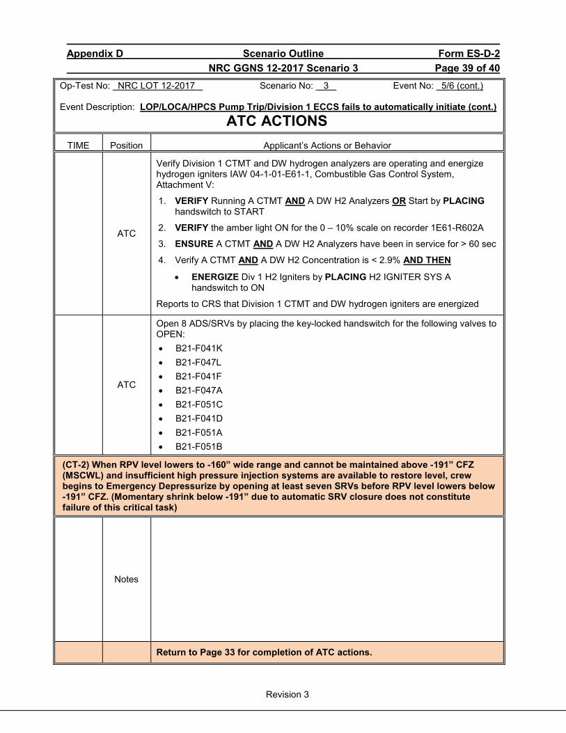
Appendix D Scenario Outline Form ES-D-2 NRC GGNS 12-2017 Scenario 3 Page 39 of 40
Revision 3
Op-Test No: NRC LOT 12-2017 Scenario No: 3 Event No: 5/6 (cont.) Event Description: LOP/LOCA/HPCS Pump Trip/Division 1 ECCS fails to automatically initiate (cont.) ATC ACTIONS
TIME Position Applicant’s Actions or Behavior
ATC
Verify Division 1 CTMT and DW hydrogen analyzers are operating and energize hydrogen igniters IAW 04-1-01-E61-1, Combustible Gas Control System, Attachment V:
1. VERIFY Running A CTMT AND A DW H2 Analyzers OR Start by PLACING handswitch to START
2. VERIFY the amber light ON for the 0 – 10% scale on recorder 1E61-R602A
3. ENSURE A CTMT AND A DW H2 Analyzers have been in service for > 60 sec
4. Verify A CTMT AND A DW H2 Concentration is < 2.9% AND THEN
• ENERGIZE Div 1 H2 Igniters by PLACING H2 IGNITER SYS A handswitch to ON
Reports to CRS that Division 1 CTMT and DW hydrogen igniters are energized
ATC
Open 8 ADS/SRVs by placing the key-locked handswitch for the following valves to OPEN: • B21-F041K • B21-F047L • B21-F041F • B21-F047A • B21-F051C • B21-F041D • B21-F051A • B21-F051B
(CT-2) When RPV level lowers to -160” wide range and cannot be maintained above -191” CFZ (MSCWL) and insufficient high pressure injection systems are available to restore level, crew begins to Emergency Depressurize by opening at least seven SRVs before RPV level lowers below -191” CFZ. (Momentary shrink below -191” due to automatic SRV closure does not constitute failure of this critical task)
Notes
Return to Page 33 for completion of ATC actions.

INITIAL CONDITIONS A. Plant Status: 100% power, middle of cycle B. Tech. Spec. Limitations in effect: None C. Significant problems/abnormalities:
1. TBCW Pump C is tagged out for motor oil replacement. 2. CRD Pump B is tagged out of service for oil replacement in the speed increaser.
D. Integrated Risk: Green E. Division Work Week: Division 2 F. Evolutions/maintenance for the up-coming shift :
1. Transfer RPS Bus B from normal to alternate power supply in preparation for maintenance on the RPS B Motor Generator.
2. The Motor Generator will be tagged out on the next shift. 3. No scram or isolation surveillances are in progress or planned for this shift.
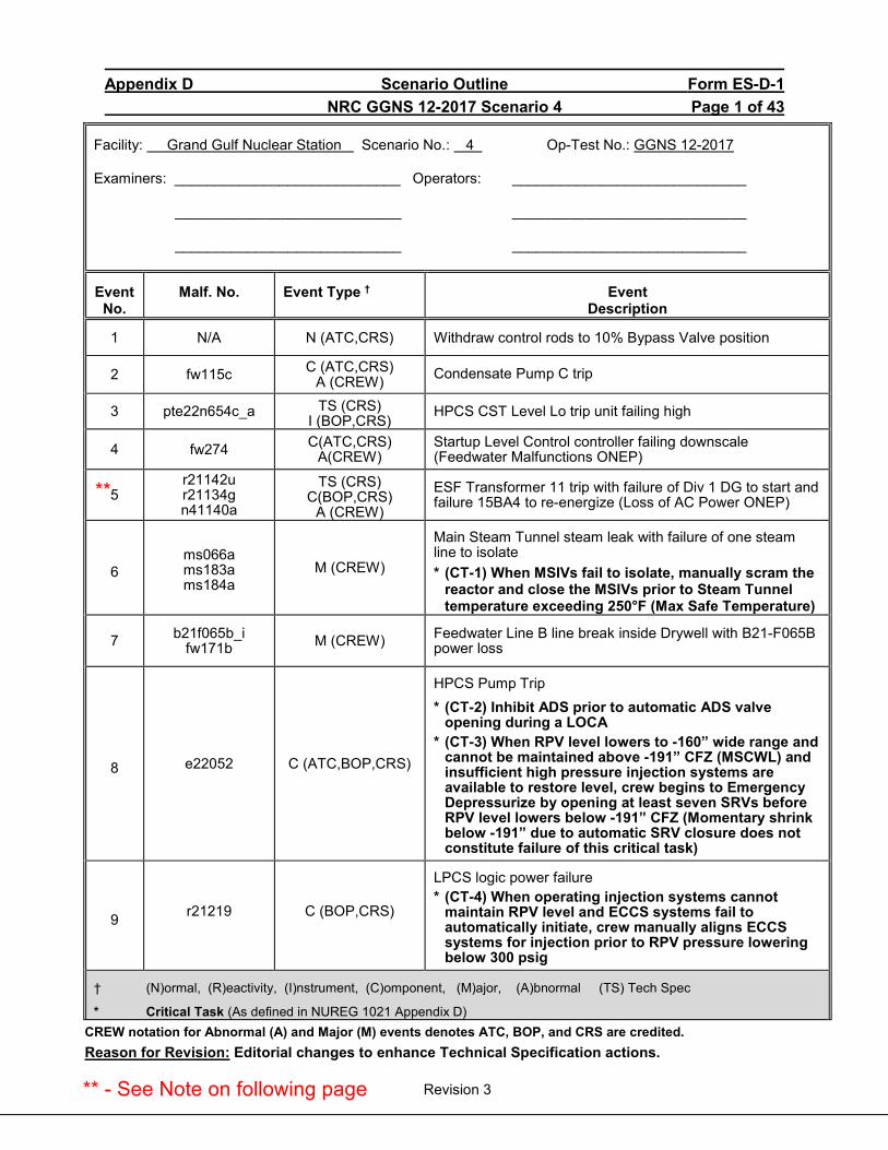
Appendix D Scenario Outline Form ES-D-1 NRC GGNS 12-2017 Scenario 4 Page 1 of 43
Revision 3
Facility: Grand Gulf Nuclear Station Scenario No.: 4 Op-Test No.: GGNS 12-2017
Examiners: ____________________________ Operators: _____________________________
____________________________ _____________________________
____________________________ _____________________________
Event No.
Malf. No. Event Type † Event Description
1 N/A N (ATC,CRS) Withdraw control rods to 10% Bypass Valve position
2 fw115c C (ATC,CRS) A (CREW) Condensate Pump C trip
3 pte22n654c_a TS (CRS) I (BOP,CRS)
HPCS CST Level Lo trip unit failing high
4 fw274 C(ATC,CRS) A(CREW)
Startup Level Control controller failing downscale (Feedwater Malfunctions ONEP)
5 r21142u r21134g n41140a
TS (CRS) C(BOP,CRS)
A (CREW)
ESF Transformer 11 trip with failure of Div 1 DG to start and failure 15BA4 to re-energize (Loss of AC Power ONEP)
6 ms066a ms183a ms184a
M (CREW)
Main Steam Tunnel steam leak with failure of one steam line to isolate * (CT-1) When MSIVs fail to isolate, manually scram the
reactor and close the MSIVs prior to Steam Tunneltemperature exceeding 250°F (Max Safe Temperature)
7 b21f065b_i fw171b M (CREW) Feedwater Line B line break inside Drywell with B21-F065B
power loss
8 e22052 C (ATC,BOP,CRS)
HPCS Pump Trip * (CT-2) Inhibit ADS prior to automatic ADS valve
opening during a LOCA* (CT-3) When RPV level lowers to -160” wide range and
cannot be maintained above -191” CFZ (MSCWL) andinsufficient high pressure injection systems areavailable to restore level, crew begins to EmergencyDepressurize by opening at least seven SRVs beforeRPV level lowers below -191” CFZ (Momentary shrinkbelow -191” due to automatic SRV closure does notconstitute failure of this critical task)
9 r21219 C (BOP,CRS)
LPCS logic power failure * (CT-4) When operating injection systems cannot
maintain RPV level and ECCS systems fail to automatically initiate, crew manually aligns ECCS systems for injection prior to RPV pressure lowering below 300 psig
† (N)ormal, (R)eactivity, (I)nstrument, (C)omponent, (M)ajor, (A)bnormal (TS) Tech Spec
* Critical Task (As defined in NUREG 1021 Appendix D)CREW notation for Abnormal (A) and Major (M) events denotes ATC, BOP, and CRS are credited. Reason for Revision: Editorial changes to enhance Technical Specification actions.
**
** - See Note on following page
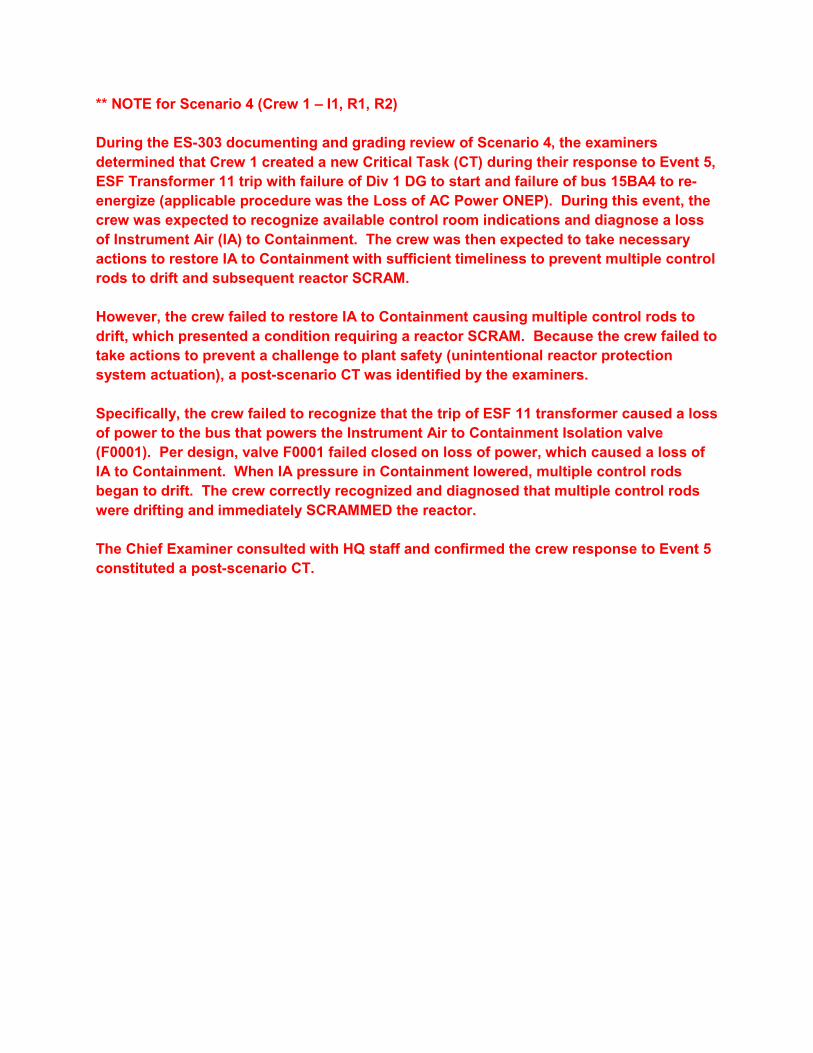
** NOTE for Scenario 4 (Crew 1 – I1, R1, R2) During the ES-303 documenting and grading review of Scenario 4, the examiners determined that Crew 1 created a new Critical Task (CT) during their response to Event 5, ESF Transformer 11 trip with failure of Div 1 DG to start and failure of bus 15BA4 to re-energize (applicable procedure was the Loss of AC Power ONEP). During this event, the crew was expected to recognize available control room indications and diagnose a loss of Instrument Air (IA) to Containment. The crew was then expected to take necessary actions to restore IA to Containment with sufficient timeliness to prevent multiple control rods to drift and subsequent reactor SCRAM. However, the crew failed to restore IA to Containment causing multiple control rods to drift, which presented a condition requiring a reactor SCRAM. Because the crew failed to take actions to prevent a challenge to plant safety (unintentional reactor protection system actuation), a post-scenario CT was identified by the examiners. Specifically, the crew failed to recognize that the trip of ESF 11 transformer caused a loss of power to the bus that powers the Instrument Air to Containment Isolation valve (F0001). Per design, valve F0001 failed closed on loss of power, which caused a loss of IA to Containment. When IA pressure in Containment lowered, multiple control rods began to drift. The crew correctly recognized and diagnosed that multiple control rods were drifting and immediately SCRAMMED the reactor. The Chief Examiner consulted with HQ staff and confirmed the crew response to Event 5 constituted a post-scenario CT.

Appendix D Scenario Outline Form ES-D-1 NRC GGNS 12-2017 Scenario 4 Page 2 of 43
Revision 3
Objectives: To evaluate the applicants’ ability to operate the facility in response to the following evolutions:
1. Withdraw control rods to 10% Bypass Valve position 2. Respond to Condensate Pump B trip. 3. Respond to a HPCS CST Level LO trip unit failing high. 4. Respond to a Startup Level Control controller failing downscale. 5. Respond to an ESF Transformer 11 trip with a failure of Div 1 DG and failure of 15BA4 to re-
energize. 6. Respond to an Main Steam Tunnel steam leak with failure of one steam line to isolate. 7. Respond to a Feedwater Line B line break inside the Drywell with B21-F065B power loss. 8. Respond to a HPCS Pump trip. 9. Respond to a LPCS logic power failure.
Initial Conditions: • Reactor power is approximately 4% power • Reactor pressure is 750 psig
Inoperable Equipment: None Turnover:
• Reactor startup is in progress: o Step 45 of IOI 03-1-01-1, Attachment XV o Step 96 of Control Rod Movement Sequence is complete o SJAE B is in service
• Condensate System is lined up as follows: o Condensate Pumps A and C in service o Condensate Booster Pump C in service o Reactor Feed Pump A in service at approximately 950 psig discharge pressure o CFFF is in service o 4 Deep-Bed Condensate Demineralizers are in service
• Annunciators P680-4A2-C5, CONT ROD WITHDRAWAL BLOCK, and P680-4A1-A7, CRD DRIVE WTR TO RX ΔP HI, are flagged as expected annunciators
Planned activities for this shift are:
• Withdraw control rods until 10% Bypass Valve position on the lagging valve, then continue raising TURB STM PRESSURE DEMAND setpoint to 935 psig per step 45 of IOI 03-1-01-1, Attachment XV
Scenario Notes: This scenario is a NEW Scenario. Validation Time: 60 minutes

Appendix D Scenario Outline Form ES-D-1 NRC GGNS 12-2017 Scenario 4 Page 3 of 43
Revision 3
Quantitative Attributes Table Attribute E3-304-1
Target Actual Description
Malfunctions after EOP entry 1-2 2
• HPCS Pump Trip E8) • LPCS Logic power failure (E9)
Abnormal Events 2-4 3
• Condensate Pump C trip (Feedwater Malfunctions ONEP) (E2)
• Startup Level Control Controller fails downscale (Feedwater Malfunctions ONEP) (E4)
• ESF Transformer 11 trip with failure of Div 1 DG to start and failure 15BA4 to re-energize (Loss of AC Power ONEP) (E5)
Major Transients 1-2 2
• Main Steam Tunnel steam leak with failure of one steam line to isolate (E6)
• Feedwater Line B line break inside the Drywell with B21-F065B power loss (E7)
EOP entries requiring substantive action 1-2 3
• EP-4 • EP-2 • EP-3
EOP contingencies requiring substantive action
0-2 2 • EP-2 Alternate Level Control • EP-2 Emergency Depressurization
EOP based Critical Tasks 2-3 4
• (CT-1) When MSIVs fail to isolate, manually scram the reactor and close the MSIVs prior to Steam Tunnel temperature exceeding 250°F (Max Safe Temperature)
• (CT-2) Inhibit ADS prior to automatic ADS valve opening during a LOCA
• (CT-3) When RPV level lowers to -160” wide range and cannot be maintained above -191” CFZ (MSCWL) and insufficient high pressure injection systems are available to restore level, crew begins to Emergency Depressurize by opening at least seven SRVs before RPV level lowers below -191” CFZ. (Momentary shrink below -191” due to automatic SRV closure does not constitute failure of this critical task.)
• (CT-4) When operating injection systems cannot maintain RPV level and ECCS systems fail to automatically initiate, crew manually aligns ECCS systems for injection prior to RPV pressure lowering below 300 psig
Normal Events N/A 1 • Withdraw control rods to 10% Bypass Valve position (E1)
Reactivity Manipulations N/A 0 • N/A
Instrument / Component failures N/A 6
• Condensate Pump C trip (E2) • HPCS CST Level LO trip unit failing high (E3) • Startup Level Control controller failing downscale (E4) • ESF Transformer 11 trip with failure of Div 1 DG to start and
failure 15BA4 to re-energize (Loss of AC Power ONEP) (E5) • HPCS Pump trip (E8) • LPCS logic power failure (E9)
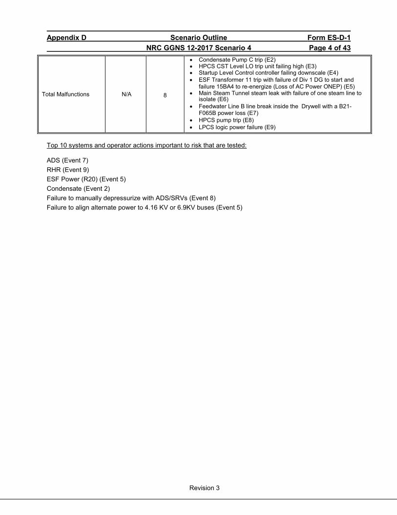
Appendix D Scenario Outline Form ES-D-1 NRC GGNS 12-2017 Scenario 4 Page 4 of 43
Revision 3
Total Malfunctions N/A 8
• Condensate Pump C trip (E2) • HPCS CST Level LO trip unit failing high (E3) • Startup Level Control controller failing downscale (E4) • ESF Transformer 11 trip with failure of Div 1 DG to start and
failure 15BA4 to re-energize (Loss of AC Power ONEP) (E5) • Main Steam Tunnel steam leak with failure of one steam line to
isolate (E6) • Feedwater Line B line break inside the Drywell with a B21-
F065B power loss (E7) • HPCS pump trip (E8) • LPCS logic power failure (E9)
Top 10 systems and operator actions important to risk that are tested:
ADS (Event 7) RHR (Event 9) ESF Power (R20) (Event 5) Condensate (Event 2) Failure to manually depressurize with ADS/SRVs (Event 8) Failure to align alternate power to 4.16 KV or 6.9KV buses (Event 5)

Appendix D Scenario Outline Form ES-D-1 NRC GGNS 12-2017 Scenario 4 Page 5 of 43
Revision 3
SCENARIO ACTIVITIES:
The plant is operating at 4% power during a reactor startup. Event 1 - Withdraw control rods to 10% Bypass Valve position
After the crew assumes the shift, the ATC will withdraw control rods in accordance with Control Rod Movement Sequence IAW SOI 04-1-01-C11-2, Rod Control and Information System. Event 2 – Condensate Pump C trip (Triggered by Lead Examiner)
At the direction of the Lead Examiner, Condensate Pump C will trip. CRS will enter 05-1-02-V-7, Feedwater System Malfunctions ONEP, and direct ATC to start Condensate Pump B IAW SOI 04-1-01-N19-1.
Event 3 - HPCS CST Level Lo trip unit failing upscale (Triggered by Lead Examiner)
After actions of Condensate Pump C trip are complete, HPCS CST Level LO trip unit, E22-N654C, will fail high. CRS will enter LCO 3.3.5.1 Condition A and, using Table 3.3.5.1-1, enter LCO 3.3.5.1 Condition D. CRS will direct BOP to transfer HPCS suction from CST to Suppression Pool IAW SOI 04-1-01-E22-1. Event 4 - Startup Level Control controller failing downscale (Triggered by Lead Examiner)
After HPCS Pump suctions are swapped and Tech Specs addressed, the Startup Level Control Controller will begin failing low, resulting in RPV level lowering. ATC will take manual control of the Startup Level Controller and restore RPV level to normal band IAW 05-1-02-V-7, Feedwater System Malfunctions ONEP, immediate actions. CRS will enter 05-1-02-V-7, Feedwater System Malfunctions ONEP.
Event 5 – ESF Transformer 11 trip with failure of 15BA4 to re-energize (Triggered by Lead Examiner)
After RPV level is stabilized, ESF Transformer 11 will trip. Division 1 Diesel Generator will fail to start. CRS will enter 05-1-02-I-4, Loss of AC Power ONEP, 05-1-02-III-5, Automatic Isolations ONEP and 05-1-02-III-1, Inadequate Decay Heat Removal ONEP. BOP will re-energize Bus 15AA from ESF Transformer 12 and restore Instrument Air to CTMT by opening P53-F001. BOP will recognize the failure of 15BA4 to re-energize. CRS will enter LCO 3.8.7, Condition A, for LCC 15BA4 failure and LCO 3.8.1.B for failure of Division 1 Diesel Generator.
NOTE: CRS is not expected to formulate plans for recovery of Fuel Pool Cooling and Cleanup or Reactor Water Cleanup systems within the time frame of this scenario.
Event 6 - Main Steam Tunnel steam leak with failure of one steam line to isolate (Triggered by Lead Examiner) When ESF Bus 15AA has been re-energized and Tech Specs addressed, a steam leak in the Auxiliary Building Main Steam Tunnel will occur. The ‘A’ Steam Line will fail to isolate. The CRS will enter EP-4 and direct the ATC to manually scram the reactor and the BOP to manually close B21-F022A, INBD MSIV, and B21-F028A, OTBD MSIV (CT-1). When the reactor is scrammed, the CRS will enter EP-2.
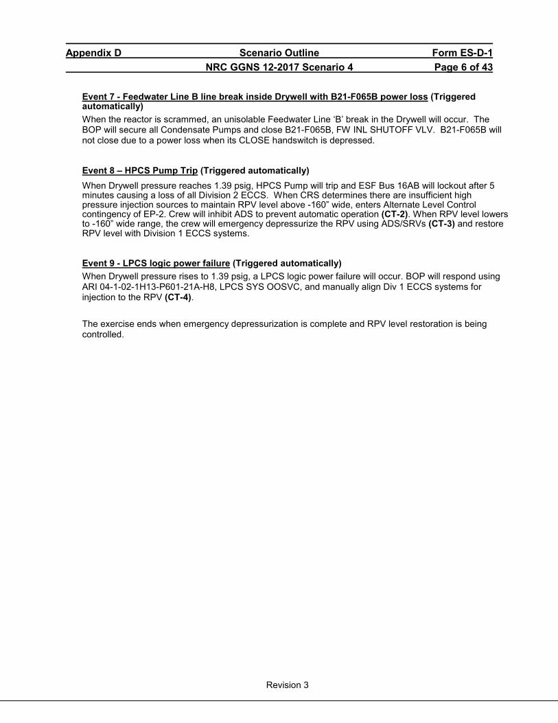
Appendix D Scenario Outline Form ES-D-1 NRC GGNS 12-2017 Scenario 4 Page 6 of 43
Revision 3
Event 7 - Feedwater Line B line break inside Drywell with B21-F065B power loss (Triggered automatically) When the reactor is scrammed, an unisolable Feedwater Line ‘B’ break in the Drywell will occur. The BOP will secure all Condensate Pumps and close B21-F065B, FW INL SHUTOFF VLV. B21-F065B will not close due to a power loss when its CLOSE handswitch is depressed.
Event 8 – HPCS Pump Trip (Triggered automatically) When Drywell pressure reaches 1.39 psig, HPCS Pump will trip and ESF Bus 16AB will lockout after 5 minutes causing a loss of all Division 2 ECCS. When CRS determines there are insufficient high pressure injection sources to maintain RPV level above -160” wide, enters Alternate Level Control contingency of EP-2. Crew will inhibit ADS to prevent automatic operation (CT-2). When RPV level lowers to -160” wide range, the crew will emergency depressurize the RPV using ADS/SRVs (CT-3) and restore RPV level with Division 1 ECCS systems. Event 9 - LPCS logic power failure (Triggered automatically) When Drywell pressure rises to 1.39 psig, a LPCS logic power failure will occur. BOP will respond using ARI 04-1-02-1H13-P601-21A-H8, LPCS SYS OOSVC, and manually align Div 1 ECCS systems for injection to the RPV (CT-4).
The exercise ends when emergency depressurization is complete and RPV level restoration is being controlled.
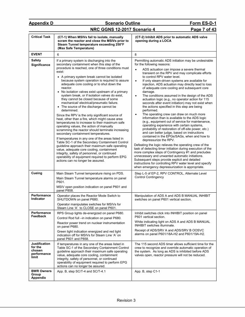
Appendix D Scenario Outline Form ES-D-1 NRC GGNS 12-2017 Scenario 4 Page 7 of 43
Revision 3
Critical Task (CT-1) When MSIVs fail to isolate, manually scram the reactor and close the MSIVs prior to Steam Tunnel temperature exceeding 250°F (Max Safe Temperature)
(CT-2) Inhibit ADS prior to automatic ADS valve opening during a LOCA
EVENT 6 8
Safety Significance
If a primary system is discharging into the secondary containment when this step of the procedure is reached, one of three conditions must exist: • A primary system break cannot be isolated
because system operation is required to assure adequate core cooling or to shut down the reactor.
• No isolation valves exist upstream of a primary system break, or if isolation valves do exist, they cannot be closed because of some mechanical/ electrical/pneumatic failure.
• The source of the discharge cannot be determined.
Since the RPV is the only significant source of heat, other than a fire, which might cause area temperatures to increase to their maximum safe operating values, the action of manually scramming the reactor should terminate increasing secondary containment temperatures. If temperatures in any one of the areas listed in Table SC-1 of the Secondary Containment Control guideline approach their maximum safe operating value, adequate core cooling, containment integrity, safety of personnel, or continued operability of equipment required to perform EPG actions can no longer be assured.
Permitting automatic ADS initiation may be undesirable for the following reasons: • ADS actuation can impose a severe thermal
transient on the RPV and may complicate efforts to control RPV water level.
• If only steam-driven systems are available for injection, ADS actuation may directly lead to loss of adequate core cooling and subsequent core damage.
• The conditions assumed in the design of the ADS actuation logic (e.g., no operator action for 115 seconds after event initiation) may not exist when the actions specified in this step are being performed.
• The operating crew can draw on much more information than is available to the ADS logic (e.g., equipment out of service for maintenance, operating experience with certain systems, probability of restoration of off-site power, etc.) and can better judge, based on instructions contained in the EPGs/SAGs, when and how to depressurize the RPV.
Defeating the logic relieves the operating crew of the task of detecting timer initiation during execution of the more complex steps of Contingency #1 and precludes unnecessary and unwanted automatic initiations. Subsequent steps provide explicit and detailed instructions for controlling RPV water level and specify when emergency depressurization is appropriate.
Cueing Main Steam Tunnel temperature rising on PDS. Main Steam Tunnel temperature alarms on panel P601. MSIV open position indication on panel P601 and panel P858.
Step L-5 of EP-2, RPV CONTROL, Alternate Level Control Contingency
Performance Indicator
Operator places the Reactor Mode Switch to SHUTDOWN on panel P680. Operator manipulates switches for MSIVs for Steam Line ‘A’ to CLOSE on panel P601.
Manipulation of ADS A and ADS B MANUAL INHIBIT switches on panel P601 vertical section.
Performance Feedback
RPS Group lights de-energized on panel P680. Control Rod full –in indication on panel P680. Reactor power trend on nuclear instrumentation on panel P680. Green light indication energized and red light indication off for MSIVs for Steam Line ‘A’ on panel P601 and P858.
Inhibit switches click into INHIBIT position on panel P601 vertical section. White indicating light on ADS A and ADS B MANUAL INHIBIT switches illuminate. Receipt of ADS/SRV A and ADS/SRV B OOSVC alarms on panel P601/18A-H2 and P601/19A-H2.
Justification for the chosen performance limit
If temperatures in any one of the areas listed in Table SC-1 of the Secondary Containment Control guideline approach their maximum safe operating value, adequate core cooling, containment integrity, safety of personnel, or continued operability of equipment required to perform EPG actions can no longer be assured.
The 115 second ADS timer allows sufficient time for the crew to recognize and override automatic operation of the system. As long as ADS is inhibited before ADS valves open, reactor pressure will not be reduced.
BWR Owners Group Appendix
App. B, step SC/T-4 and SC/T-4.1
App. B, step C1-1
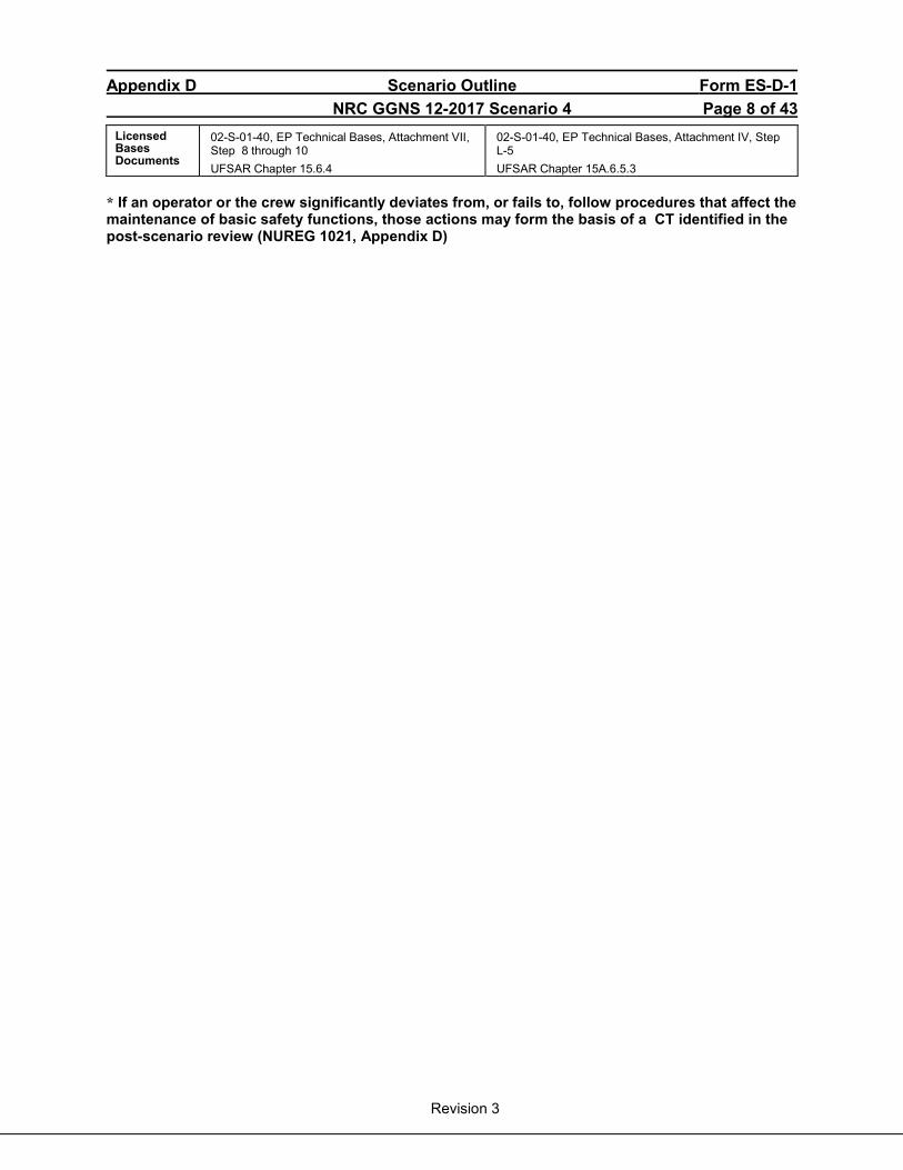
Appendix D Scenario Outline Form ES-D-1 NRC GGNS 12-2017 Scenario 4 Page 8 of 43
Revision 3
Licensed Bases Documents
02-S-01-40, EP Technical Bases, Attachment VII, Step 8 through 10 UFSAR Chapter 15.6.4
02-S-01-40, EP Technical Bases, Attachment IV, Step L-5 UFSAR Chapter 15A.6.5.3
* If an operator or the crew significantly deviates from, or fails to, follow procedures that affect the maintenance of basic safety functions, those actions may form the basis of a CT identified in the post-scenario review (NUREG 1021, Appendix D)
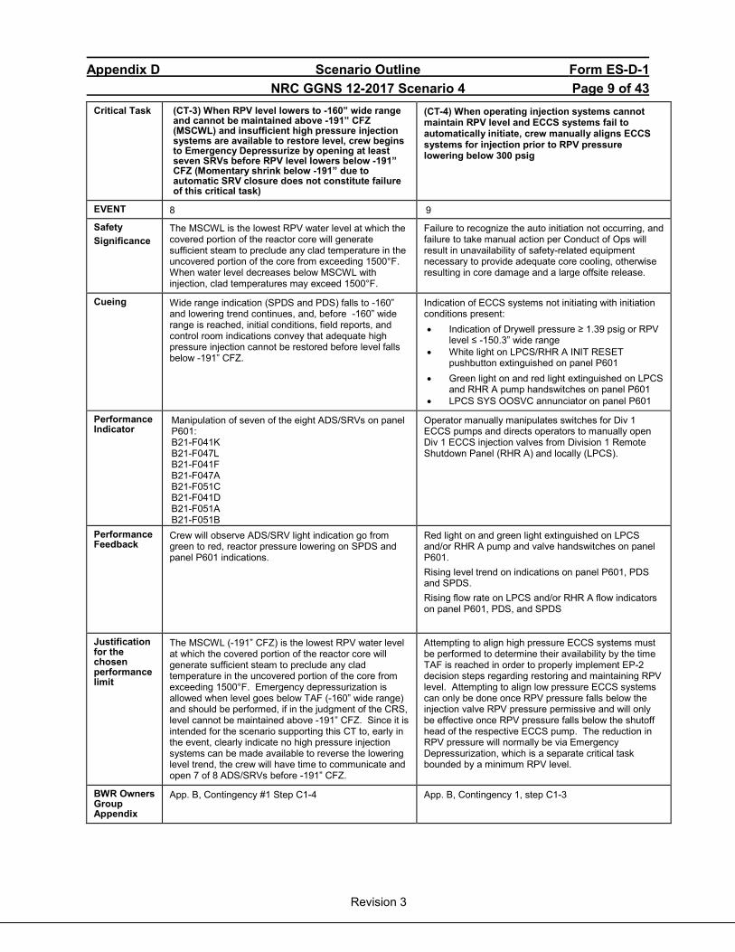
Appendix D Scenario Outline Form ES-D-1 NRC GGNS 12-2017 Scenario 4 Page 9 of 43
Revision 3
Critical Task (CT-3) When RPV level lowers to -160” wide range and cannot be maintained above -191” CFZ (MSCWL) and insufficient high pressure injection systems are available to restore level, crew begins to Emergency Depressurize by opening at least seven SRVs before RPV level lowers below -191” CFZ (Momentary shrink below -191” due to automatic SRV closure does not constitute failure of this critical task)
(CT-4) When operating injection systems cannot maintain RPV level and ECCS systems fail to automatically initiate, crew manually aligns ECCS systems for injection prior to RPV pressure lowering below 300 psig
EVENT 8 9
Safety Significance
The MSCWL is the lowest RPV water level at which the covered portion of the reactor core will generate sufficient steam to preclude any clad temperature in the uncovered portion of the core from exceeding 1500°F. When water level decreases below MSCWL with injection, clad temperatures may exceed 1500°F.
Failure to recognize the auto initiation not occurring, and failure to take manual action per Conduct of Ops will result in unavailability of safety-related equipment necessary to provide adequate core cooling, otherwise resulting in core damage and a large offsite release.
Cueing Wide range indication (SPDS and PDS) falls to -160” and lowering trend continues, and, before -160” wide range is reached, initial conditions, field reports, and control room indications convey that adequate high pressure injection cannot be restored before level falls below -191” CFZ.
Indication of ECCS systems not initiating with initiation conditions present: • Indication of Drywell pressure ≥ 1.39 psig or RPV
level ≤ -150.3” wide range • White light on LPCS/RHR A INIT RESET
pushbutton extinguished on panel P601 • Green light on and red light extinguished on LPCS
and RHR A pump handswitches on panel P601 • LPCS SYS OOSVC annunciator on panel P601
Performance Indicator
Manipulation of seven of the eight ADS/SRVs on panel P601: B21-F041K B21-F047L B21-F041F B21-F047A B21-F051C B21-F041D B21-F051A B21-F051B
Operator manually manipulates switches for Div 1 ECCS pumps and directs operators to manually open Div 1 ECCS injection valves from Division 1 Remote Shutdown Panel (RHR A) and locally (LPCS).
Performance Feedback
Crew will observe ADS/SRV light indication go from green to red, reactor pressure lowering on SPDS and panel P601 indications.
Red light on and green light extinguished on LPCS and/or RHR A pump and valve handswitches on panel P601. Rising level trend on indications on panel P601, PDS and SPDS. Rising flow rate on LPCS and/or RHR A flow indicators on panel P601, PDS, and SPDS
Justification for the chosen performance limit
The MSCWL (-191” CFZ) is the lowest RPV water level at which the covered portion of the reactor core will generate sufficient steam to preclude any clad temperature in the uncovered portion of the core from exceeding 1500°F. Emergency depressurization is allowed when level goes below TAF (-160” wide range) and should be performed, if in the judgment of the CRS, level cannot be maintained above -191” CFZ. Since it is intended for the scenario supporting this CT to, early in the event, clearly indicate no high pressure injection systems can be made available to reverse the lowering level trend, the crew will have time to communicate and open 7 of 8 ADS/SRVs before -191” CFZ.
Attempting to align high pressure ECCS systems must be performed to determine their availability by the time TAF is reached in order to properly implement EP-2 decision steps regarding restoring and maintaining RPV level. Attempting to align low pressure ECCS systems can only be done once RPV pressure falls below the injection valve RPV pressure permissive and will only be effective once RPV pressure falls below the shutoff head of the respective ECCS pump. The reduction in RPV pressure will normally be via Emergency Depressurization, which is a separate critical task bounded by a minimum RPV level.
BWR Owners Group Appendix
App. B, Contingency #1 Step C1-4
App. B, Contingency 1, step C1-3
Appendix D Scenario Outline Form ES-D-1 NRC GGNS 12-2017 Scenario 4 Page 10 of 43
Revision 3
Licensed Bases Documents
02-S-01-40, EP Technical Bases, Attachment IV, Step L-7 – through L-13 UFSAR Chapter 15A.6.5.3
02-S-01-40, EP Technical Bases, Attachment IV, Step L-14 UFSAR Chapter 15A.6.5.3
* If an operator or the crew significantly deviates from, or fails to, follow procedures that affect the maintenance of basic safety functions, those actions may form the basis of a CT identified in the post-scenario review (NUREG 1021, Appendix D)

Appendix D Scenario Outline Form ES-D-2 NRC GGNS 12-2017 Scenario 4 Page 11 of 43
Revision 3
Simulator Setup:
A. Initialization
1. Log off all simulator PDS and SPDS computers (PDS and SPDS must come up after the simulator load for proper operation).
2. Startup the simulator using Simulator Instructor’s Job Aid section 7.3.
3. Open Schedule.exe and Director.exe by clicking on the Icon in the Thunder Bar.
4. Set the Simulator to IC-103 and perform switch check (Using Quick Reset in
Director). 5. Click on “Open” in the Schedule window and Open Schedule File
“12-2017 NRC Exam Scenario 4.sch” (in the Schedule Directory)
6. In Schedule window, click on the “Stopped” red block. The red block will change to
a green arrow and indicate the scenario is active (“Running”).
Note: Prior to running the Schedule File, ensure no Event Files are Open. If an existing Event File is Open prior to running the Schedule File, then any associated Event Files will not automatically load.
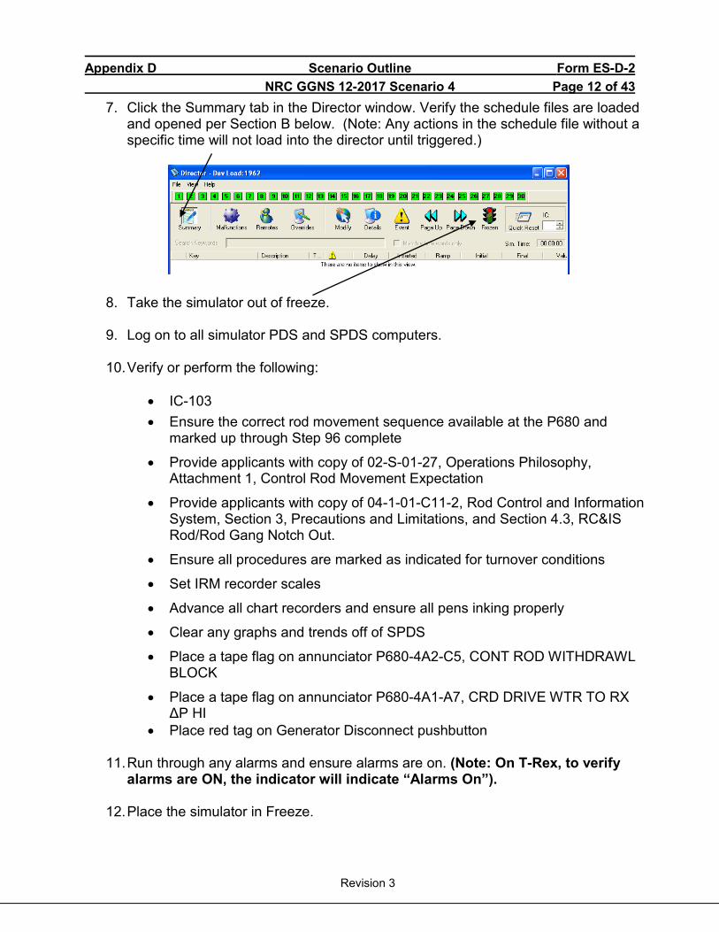
Appendix D Scenario Outline Form ES-D-2 NRC GGNS 12-2017 Scenario 4 Page 12 of 43
Revision 3
7. Click the Summary tab in the Director window. Verify the schedule files are loaded and opened per Section B below. (Note: Any actions in the schedule file without a specific time will not load into the director until triggered.)
8. Take the simulator out of freeze.
9. Log on to all simulator PDS and SPDS computers.
10. Verify or perform the following:
• IC-103 • Ensure the correct rod movement sequence available at the P680 and
marked up through Step 96 complete
• Provide applicants with copy of 02-S-01-27, Operations Philosophy, Attachment 1, Control Rod Movement Expectation
• Provide applicants with copy of 04-1-01-C11-2, Rod Control and Information System, Section 3, Precautions and Limitations, and Section 4.3, RC&IS Rod/Rod Gang Notch Out.
• Ensure all procedures are marked as indicated for turnover conditions
• Set IRM recorder scales
• Advance all chart recorders and ensure all pens inking properly
• Clear any graphs and trends off of SPDS
• Place a tape flag on annunciator P680-4A2-C5, CONT ROD WITHDRAWL BLOCK
• Place a tape flag on annunciator P680-4A1-A7, CRD DRIVE WTR TO RX ΔP HI
• Place red tag on Generator Disconnect pushbutton
11. Run through any alarms and ensure alarms are on. (Note: On T-Rex, to verify alarms are ON, the indicator will indicate “Alarms On”).
12. Place the simulator in Freeze.
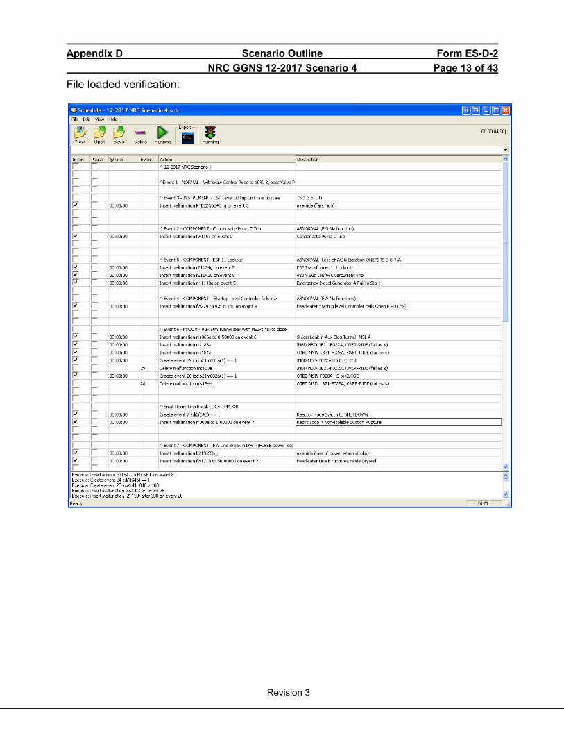
Appendix D Scenario Outline Form ES-D-2 NRC GGNS 12-2017 Scenario 4 Page 13 of 43
Revision 3
File loaded verification:
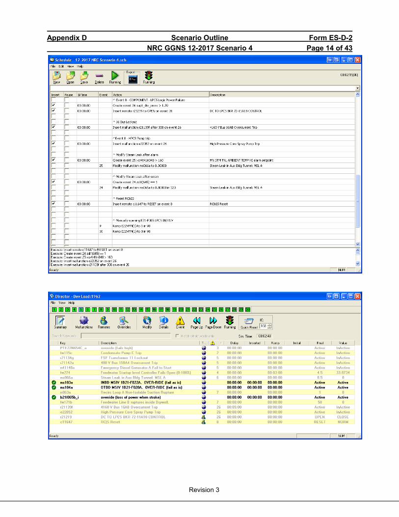
Appendix D Scenario Outline Form ES-D-2 NRC GGNS 12-2017 Scenario 4 Page 14 of 43
Revision 3

Appendix D Scenario Outline Form ES-D-2 NRC GGNS 12-2017 Scenario 4 Page 15 of 43
Revision 3
Procedures that may be used in this scenario:
Procedure No. Rev Procedure Title 03-1-01-IOI-1 172 Cold Shutdown To Generator Carrying Minimum Load 04-1-01-C11-1 154 Control Rod Drive Hydraulic System 04-1-01-C41-1 123 Standby Liquid Control System 04-1-01-E12-1 147 Residual Heat Removal System 04-1-01-N21-1 74 Feedwater System 04-1-01-N32-2 33 Turbine Generator Control 04-1-01-R21-17 10 ESF Bus 17AC 04-1-02-1H13-P601 161 Alarm Response Instruction Panel No.: 1H13-P601 04-1-02-1H13-P680 233 Alarm Response Instruction Panel No.:1H13-P680 04-1-02-1H13-P864 31 Alarm Response Instruction Panel No.: 1H13-P864 04-1-02-1H13-P870 154 Alarm Response Instruction Panel No.: 1H13-P870 04-S-02-SH13-P807 32 Alarm Response Instruction Panel No.: SH13-P807 05-1-02-I-1 130 Reactor Scram 05-1-02-I-2 37 Turbine and Generator Trips 05-1-02-I-4 51 Loss of AC Power 05-1-02-III-3 115 Reduction In Recirculation System Flow Rate 05-1-02-III-5 49 Automatic Isolations 05-1-02-IV-1 117 Control Rod / Drive Malfunctions 05-S-01-EP-1 36 Emergency / Severe Accident Procedure Support Documents 05-S-01-EP-2 45 RPV Control Tech Spec 3.1.3 Tech Spec 3.8.1
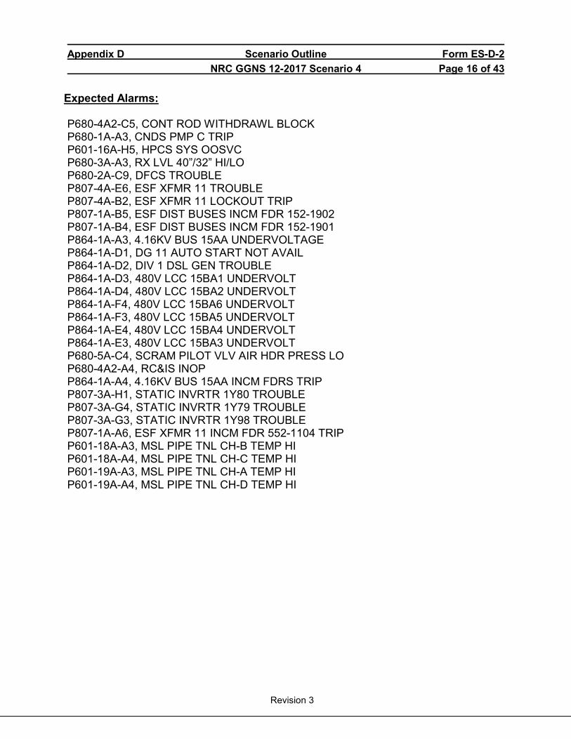
Appendix D Scenario Outline Form ES-D-2 NRC GGNS 12-2017 Scenario 4 Page 16 of 43
Revision 3
Expected Alarms:
P680-4A2-C5, CONT ROD WITHDRAWL BLOCK P680-1A-A3, CNDS PMP C TRIP P601-16A-H5, HPCS SYS OOSVC P680-3A-A3, RX LVL 40”/32” HI/LO P680-2A-C9, DFCS TROUBLE P807-4A-E6, ESF XFMR 11 TROUBLE P807-4A-B2, ESF XFMR 11 LOCKOUT TRIP P807-1A-B5, ESF DIST BUSES INCM FDR 152-1902 P807-1A-B4, ESF DIST BUSES INCM FDR 152-1901 P864-1A-A3, 4.16KV BUS 15AA UNDERVOLTAGE P864-1A-D1, DG 11 AUTO START NOT AVAIL P864-1A-D2, DIV 1 DSL GEN TROUBLE P864-1A-D3, 480V LCC 15BA1 UNDERVOLT P864-1A-D4, 480V LCC 15BA2 UNDERVOLT P864-1A-F4, 480V LCC 15BA6 UNDERVOLT P864-1A-F3, 480V LCC 15BA5 UNDERVOLT P864-1A-E4, 480V LCC 15BA4 UNDERVOLT P864-1A-E3, 480V LCC 15BA3 UNDERVOLT P680-5A-C4, SCRAM PILOT VLV AIR HDR PRESS LO P680-4A2-A4, RC&IS INOP P864-1A-A4, 4.16KV BUS 15AA INCM FDRS TRIP P807-3A-H1, STATIC INVRTR 1Y80 TROUBLE P807-3A-G4, STATIC INVRTR 1Y79 TROUBLE P807-3A-G3, STATIC INVRTR 1Y98 TROUBLE P807-1A-A6, ESF XFMR 11 INCM FDR 552-1104 TRIP P601-18A-A3, MSL PIPE TNL CH-B TEMP HI P601-18A-A4, MSL PIPE TNL CH-C TEMP HI P601-19A-A3, MSL PIPE TNL CH-A TEMP HI P601-19A-A4, MSL PIPE TNL CH-D TEMP HI

Appendix D Scenario Outline Form ES-D-2 NRC GGNS 12-2017 Scenario 4 Page 17 of 43
Revision 3
SCENARIO ACTIVITIES: • Start SBT report and any other required recording devices.
Op-Test No: NRC LOT 12-2017 Scenario No: 4 Event No: 1 Event Description: Withdraw control rods to 10% Bypass Valve position
NOTE to Examiner: Obtaining 10% Bypass Valve position is not required to satisfy this event. Next event can be triggered when Examiner is satisfied with the applicants’ performance.
TIME Position Applicant’s Actions or Behavior
ATC
Withdraw control rods IAW the approved Control Rod Movement Sequence, starting at Step 97, and 04-1-01-C11-2, Rod Control and Information System, until the lagging Main Turbine Bypass Valve is 10% open 4.3.2.a Select either INDIVIDUAL OR GANG DRIVE mode using DRIVE MODE
pushbutton on OCM and check that SELECTED DRIVE mode indicating comes ON
ATC selects INDIVIDUAL DRIVE mode using DRIVE MODE pushbutton and verifying INDIV DRIVE light energized. Performs the following actions to withdraw Control Rods 20-21EE, 44-45LL, 44,21LE and 20-45EL from position 04 to position 08 4.3.2.b Select rod/rod gang to be moved by depressing corresponding ROD
SELECT pushbuttons on Rod Select panel on 1H13-P680 4.3.2.c Check rod position(s) is displayed for selected rod/rod gang on RDM
NOTE A rod gang selection should have the GANG position displayed also on the RDM.
CAUTION If Control Rod blocks occur, the cause must be determined and corrective action taken before further Control Rod withdrawal can take place for that Control Rod.
4.3.2.d Check that selected rod/rod gang is allowed to be withdrawn by RPC by:
• Observing WITHDRAW BLOCK light is OFF OR • Depressing WITHDRAW OK pushbutton on OCM
AND • observing a green status light on RDM for that rod/rod gang
4.3.2.e Momentarily depress WITHDRAW pushbutton and observe the following: (1) The IN light energizes momentarily, then goes OFF (2) The DATA FAULT light may flash ON, then OFF if RAW DATA is
selected (3) The OUT light will come ON, then go OFF (4) SETTLE light comes ON for approximately 6.0 seconds (5) ROD/GANG position on RDM shows new ROD/GANG position (6) Monitor nuclear instrumentation for changes in indication
4..3.2.g Withdraw each rod/rod gang in accordance with selected sequence provided by Reactor Engineering
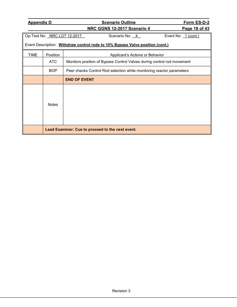
Appendix D Scenario Outline Form ES-D-2 NRC GGNS 12-2017 Scenario 4 Page 18 of 43
Revision 3
Op-Test No: NRC LOT 12-2017 Scenario No: 4 Event No: 1 (cont.) Event Description: Withdraw control rods to 10% Bypass Valve position (cont.)
TIME Position Applicant’s Actions or Behavior
ATC Monitors position of Bypass Control Valves during control rod movement
BOP Peer checks Control Rod selection while monitoring reactor parameters
END OF EVENT
Notes
Lead Examiner: Cue to proceed to the next event.
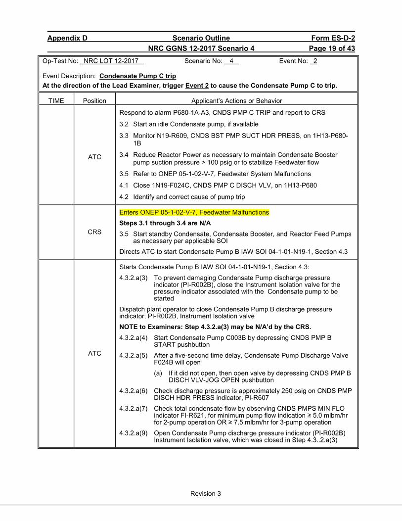
Appendix D Scenario Outline Form ES-D-2 NRC GGNS 12-2017 Scenario 4 Page 19 of 43
Revision 3
Op-Test No: NRC LOT 12-2017 Scenario No: 4 Event No: 2 Event Description: Condensate Pump C trip At the direction of the Lead Examiner, trigger Event 2 to cause the Condensate Pump C to trip.
TIME Position Applicant’s Actions or Behavior
ATC
Respond to alarm P680-1A-A3, CNDS PMP C TRIP and report to CRS
3.2 Start an idle Condensate pump, if available
3.3 Monitor N19-R609, CNDS BST PMP SUCT HDR PRESS, on 1H13-P680-1B
3.4 Reduce Reactor Power as necessary to maintain Condensate Booster pump suction pressure > 100 psig or to stabilize Feedwater flow
3.5 Refer to ONEP 05-1-02-V-7, Feedwater System Malfunctions
4.1 Close 1N19-F024C, CNDS PMP C DISCH VLV, on 1H13-P680
4.2 Identify and correct cause of pump trip
CRS
Enters ONEP 05-1-02-V-7, Feedwater Malfunctions Steps 3.1 through 3.4 are N/A 3.5 Start standby Condensate, Condensate Booster, and Reactor Feed Pumps
as necessary per applicable SOI Directs ATC to start Condensate Pump B IAW SOI 04-1-01-N19-1, Section 4.3
ATC
Starts Condensate Pump B IAW SOI 04-1-01-N19-1, Section 4.3: 4.3.2.a(3) To prevent damaging Condensate Pump discharge pressure
indicator (PI-R002B), close the Instrument Isolation valve for the pressure indicator associated with the Condensate pump to be started
Dispatch plant operator to close Condensate Pump B discharge pressure indicator, PI-R002B, Instrument Isolation valve NOTE to Examiners: Step 4.3.2.a(3) may be N/A’d by the CRS. 4.3.2.a(4) Start Condensate Pump C003B by depressing CNDS PMP B
START pushbutton 4.3.2.a(5) After a five-second time delay, Condensate Pump Discharge Valve
F024B will open (a) If it did not open, then open valve by depressing CNDS PMP B
DISCH VLV-JOG OPEN pushbutton 4.3.2.a(6) Check discharge pressure is approximately 250 psig on CNDS PMP
DISCH HDR PRESS indicator, PI-R607 4.3.2.a(7) Check total condensate flow by observing CNDS PMPS MIN FLO
indicator FI-R621, for minimum pump flow indication ≥ 5.0 mlbm/hr for 2-pump operation OR ≥ 7.5 mlbm/hr for 3-pump operation
4.3.2.a(9) Open Condensate Pump discharge pressure indicator (PI-R002B) Instrument Isolation valve, which was closed in Step 4.3..2.a(3)

Appendix D Scenario Outline Form ES-D-2 NRC GGNS 12-2017 Scenario 4 Page 20 of 43
Revision 3
Op-Test No: NRC LOT 12-2017 Scenario No: 4 Event No: 2 (cont.) Event Description: Condensate Pump C trip (cont.)
TIME Position Applicant’s Actions or Behavior
BOOTH
If contacted to close Condensate Pump B discharge pressure indicator, PI-R002B, Instrument Isolation valve, after 2 minutes report as plant operator that valve is closed If contacted to open Condensate Pump B discharge pressure indicator, PI-R002B, Instrument Isolation valve, after 1 minutes report as plant operator that valve is open
CREW
Dispatch plant operator / electrical maintenance to investigate Condensate Pump C trip Dispatch plant operator to perform post-start checks on Condensate Pump B
BOOTH
If contacted, after 2 minutes report as plant operator that breaker 152-1409 for Condensate Pump C has tripped on timed overcurrent and electrical maintenance is investigating If contacted, after 2 minutes report as plant operator that post-start checks on Condensate Pump B are satisfactory
END OF EVENT
Notes
Lead Examiner: Cue to proceed to the next event
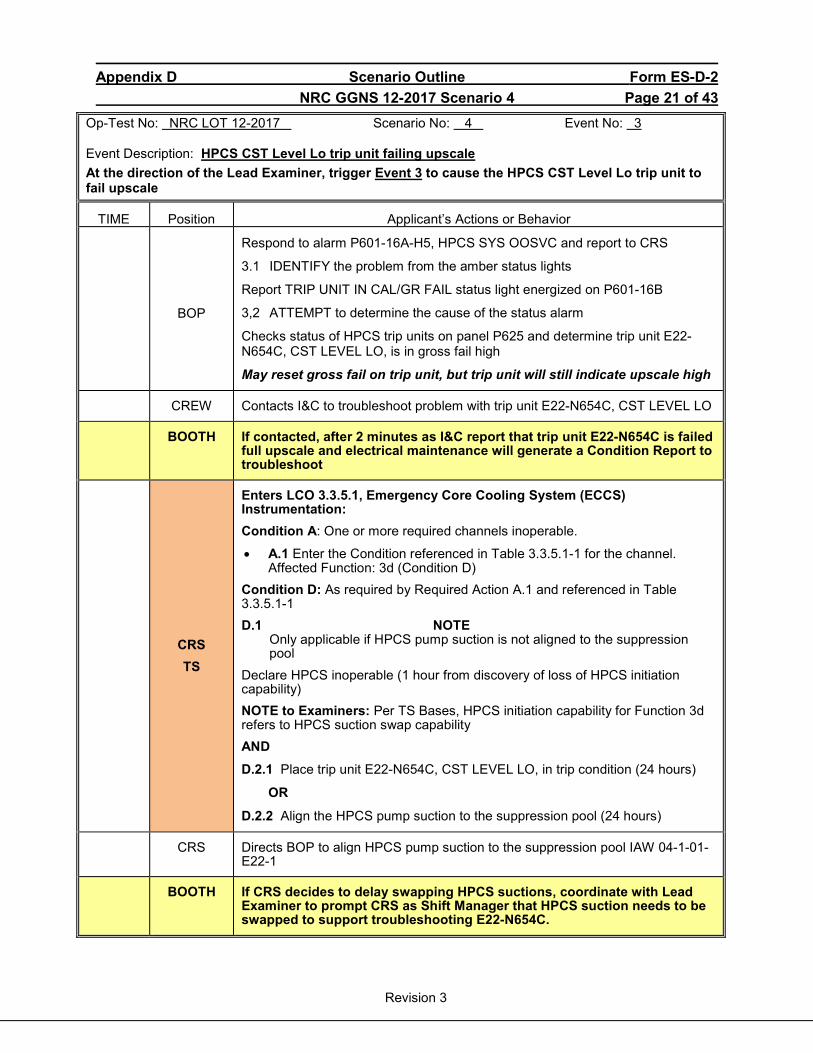
Appendix D Scenario Outline Form ES-D-2 NRC GGNS 12-2017 Scenario 4 Page 21 of 43
Revision 3
Op-Test No: NRC LOT 12-2017 Scenario No: 4 Event No: 3 Event Description: HPCS CST Level Lo trip unit failing upscale At the direction of the Lead Examiner, trigger Event 3 to cause the HPCS CST Level Lo trip unit to fail upscale
TIME Position Applicant’s Actions or Behavior
BOP
Respond to alarm P601-16A-H5, HPCS SYS OOSVC and report to CRS
3.1 IDENTIFY the problem from the amber status lights
Report TRIP UNIT IN CAL/GR FAIL status light energized on P601-16B
3,2 ATTEMPT to determine the cause of the status alarm
Checks status of HPCS trip units on panel P625 and determine trip unit E22-N654C, CST LEVEL LO, is in gross fail high
May reset gross fail on trip unit, but trip unit will still indicate upscale high
CREW Contacts I&C to troubleshoot problem with trip unit E22-N654C, CST LEVEL LO
BOOTH If contacted, after 2 minutes as I&C report that trip unit E22-N654C is failed full upscale and electrical maintenance will generate a Condition Report to troubleshoot
CRS TS
Enters LCO 3.3.5.1, Emergency Core Cooling System (ECCS) Instrumentation: Condition A: One or more required channels inoperable.
• A.1 Enter the Condition referenced in Table 3.3.5.1-1 for the channel. Affected Function: 3d (Condition D)
Condition D: As required by Required Action A.1 and referenced in Table 3.3.5.1-1 D.1 NOTE Only applicable if HPCS pump suction is not aligned to the suppression
pool Declare HPCS inoperable (1 hour from discovery of loss of HPCS initiation capability) NOTE to Examiners: Per TS Bases, HPCS initiation capability for Function 3d refers to HPCS suction swap capability AND D.2.1 Place trip unit E22-N654C, CST LEVEL LO, in trip condition (24 hours)
OR
D.2.2 Align the HPCS pump suction to the suppression pool (24 hours)
CRS Directs BOP to align HPCS pump suction to the suppression pool IAW 04-1-01-E22-1
BOOTH If CRS decides to delay swapping HPCS suctions, coordinate with Lead Examiner to prompt CRS as Shift Manager that HPCS suction needs to be swapped to support troubleshooting E22-N654C.
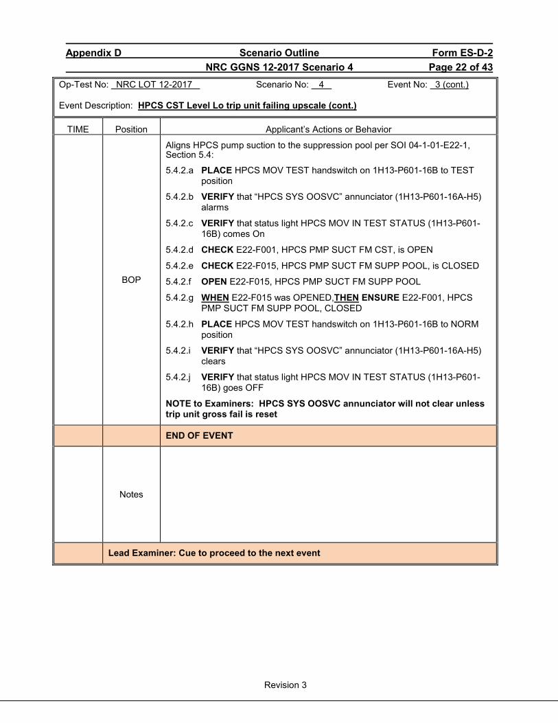
Appendix D Scenario Outline Form ES-D-2 NRC GGNS 12-2017 Scenario 4 Page 22 of 43
Revision 3
Op-Test No: NRC LOT 12-2017 Scenario No: 4 Event No: 3 (cont.) Event Description: HPCS CST Level Lo trip unit failing upscale (cont.)
TIME Position Applicant’s Actions or Behavior
BOP
Aligns HPCS pump suction to the suppression pool per SOI 04-1-01-E22-1, Section 5.4:
5.4.2.a PLACE HPCS MOV TEST handswitch on 1H13-P601-16B to TEST position
5.4.2.b VERIFY that “HPCS SYS OOSVC” annunciator (1H13-P601-16A-H5) alarms
5.4.2.c VERIFY that status light HPCS MOV IN TEST STATUS (1H13-P601-16B) comes On
5.4.2.d CHECK E22-F001, HPCS PMP SUCT FM CST, is OPEN
5.4.2.e CHECK E22-F015, HPCS PMP SUCT FM SUPP POOL, is CLOSED
5.4.2.f OPEN E22-F015, HPCS PMP SUCT FM SUPP POOL
5.4.2.g WHEN E22-F015 was OPENED,THEN ENSURE E22-F001, HPCS PMP SUCT FM SUPP POOL, CLOSED
5.4.2.h PLACE HPCS MOV TEST handswitch on 1H13-P601-16B to NORM position
5.4.2.i VERIFY that “HPCS SYS OOSVC” annunciator (1H13-P601-16A-H5) clears
5.4.2.j VERIFY that status light HPCS MOV IN TEST STATUS (1H13-P601-16B) goes OFF
NOTE to Examiners: HPCS SYS OOSVC annunciator will not clear unless trip unit gross fail is reset
END OF EVENT
Notes
Lead Examiner: Cue to proceed to the next event

Appendix D Scenario Outline Form ES-D-2 NRC GGNS 12-2017 Scenario 4 Page 23 of 43
Revision 3
Op-Test No: NRC LOT 12-2017 Scenario No: 4 Event No: 4 Event Description: Startup Level Control controller failing downscale At the direction of the Lead Examiner, trigger Event 4 to cause the Startup Level Control controller to begin failing downscale
TIME Position Applicant’s Actions or Behavior
BOP
Recognize and report Startup Level Control Valve controller failing downscale
• P680-3A-A3, RX LVL 40”/32” HI/LO • Startup Level Controller C34-LK-R602 on P680-1D output lowering
CRS
Enters ONEP 05-1-02-V-7, Feedwater Malfunctions 2.2 IF Feedwater System Controller malfunction has occurred, THEN PLACE
affected controller in MANUAL AND OPERATE as necessary to control reactor water level
Directs ATC to place Startup Level Control controller in MANUAL and control RPV level between +32 inches and + 42 inches narrow range
ATC
Places Startup Level Control controller in MANUAL and operates as necessary in MANUAL to control RPV level between +32 inches and +42 inches narrow range IAW ONEP 05-1-02-V-7, Feedwater Malfunctions
• P680-2A-C9 DFCS TROUBLE alarm expected
CREW Contacts Work Control/I&C to investigate failure of Startup Level Control Valve controller
BOOTH If contacted, as I&C report after 2 minutes that Startup Level Control Valve controller will require a Condition Report for troubleshooting
END OF EVENT
Notes
Lead Examiner: Cue to proceed to the next event
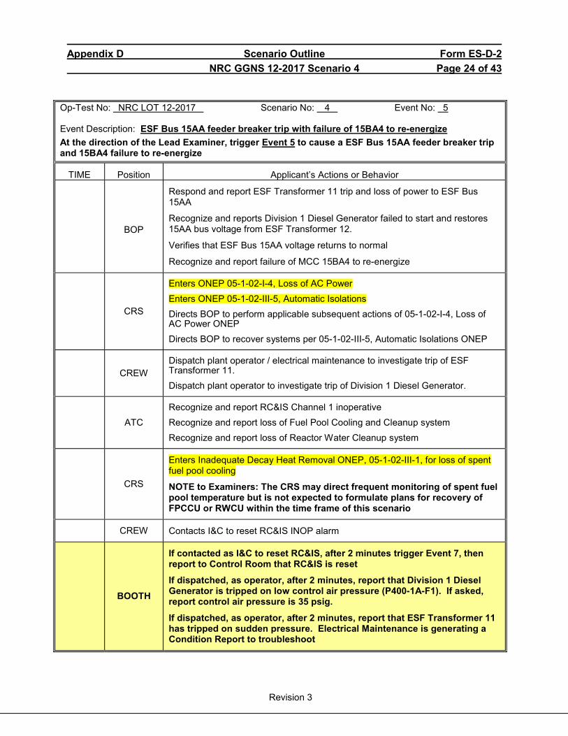
Appendix D Scenario Outline Form ES-D-2 NRC GGNS 12-2017 Scenario 4 Page 24 of 43
Revision 3
Op-Test No: NRC LOT 12-2017 Scenario No: 4 Event No: 5 Event Description: ESF Bus 15AA feeder breaker trip with failure of 15BA4 to re-energize At the direction of the Lead Examiner, trigger Event 5 to cause a ESF Bus 15AA feeder breaker trip and 15BA4 failure to re-energize
TIME Position Applicant’s Actions or Behavior
BOP
Respond and report ESF Transformer 11 trip and loss of power to ESF Bus 15AA
Recognize and reports Division 1 Diesel Generator failed to start and restores 15AA bus voltage from ESF Transformer 12.
Verifies that ESF Bus 15AA voltage returns to normal
Recognize and report failure of MCC 15BA4 to re-energize
CRS
Enters ONEP 05-1-02-I-4, Loss of AC Power Enters ONEP 05-1-02-III-5, Automatic Isolations Directs BOP to perform applicable subsequent actions of 05-1-02-I-4, Loss of AC Power ONEP Directs BOP to recover systems per 05-1-02-III-5, Automatic Isolations ONEP
CREW
Dispatch plant operator / electrical maintenance to investigate trip of ESF Transformer 11. Dispatch plant operator to investigate trip of Division 1 Diesel Generator.
ATC
Recognize and report RC&IS Channel 1 inoperative Recognize and report loss of Fuel Pool Cooling and Cleanup system Recognize and report loss of Reactor Water Cleanup system
CRS
Enters Inadequate Decay Heat Removal ONEP, 05-1-02-III-1, for loss of spent fuel pool cooling
NOTE to Examiners: The CRS may direct frequent monitoring of spent fuel pool temperature but is not expected to formulate plans for recovery of FPCCU or RWCU within the time frame of this scenario
CREW Contacts I&C to reset RC&IS INOP alarm
BOOTH
If contacted as I&C to reset RC&IS, after 2 minutes trigger Event 7, then report to Control Room that RC&IS is reset
If dispatched, as operator, after 2 minutes, report that Division 1 Diesel Generator is tripped on low control air pressure (P400-1A-F1). If asked, report control air pressure is 35 psig.
If dispatched, as operator, after 2 minutes, report that ESF Transformer 11 has tripped on sudden pressure. Electrical Maintenance is generating a Condition Report to troubleshoot
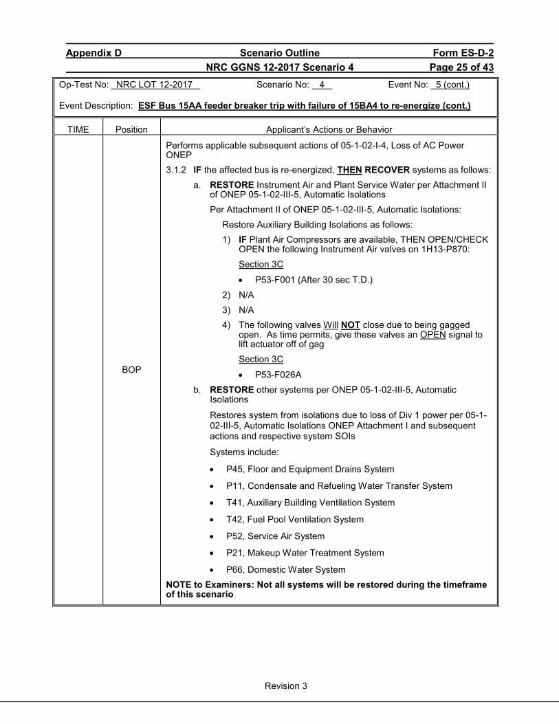
Appendix D Scenario Outline Form ES-D-2 NRC GGNS 12-2017 Scenario 4 Page 25 of 43
Revision 3
Op-Test No: NRC LOT 12-2017 Scenario No: 4 Event No: 5 (cont.) Event Description: ESF Bus 15AA feeder breaker trip with failure of 15BA4 to re-energize (cont.)
TIME Position Applicant’s Actions or Behavior
BOP
Performs applicable subsequent actions of 05-1-02-I-4, Loss of AC Power ONEP 3.1.2 IF the affected bus is re-energized, THEN RECOVER systems as follows:
a. RESTORE Instrument Air and Plant Service Water per Attachment II of ONEP 05-1-02-III-5, Automatic Isolations Per Attachment II of ONEP 05-1-02-III-5, Automatic Isolations:
Restore Auxiliary Building Isolations as follows: 1) IF Plant Air Compressors are available, THEN OPEN/CHECK
OPEN the following Instrument Air valves on 1H13-P870: Section 3C
• P53-F001 (After 30 sec T.D.) 2) N/A 3) N/A 4) The following valves Will NOT close due to being gagged
open. As time permits, give these valves an OPEN signal to lift actuator off of gag
Section 3C
• P53-F026A b. RESTORE other systems per ONEP 05-1-02-III-5, Automatic
Isolations
Restores system from isolations due to loss of Div 1 power per 05-1-02-III-5, Automatic Isolations ONEP Attachment I and subsequent actions and respective system SOIs
Systems include:
• P45, Floor and Equipment Drains System
• P11, Condensate and Refueling Water Transfer System
• T41, Auxiliary Building Ventilation System
• T42, Fuel Pool Ventilation System
• P52, Service Air System
• P21, Makeup Water Treatment System
• P66, Domestic Water System NOTE to Examiners: Not all systems will be restored during the timeframe of this scenario
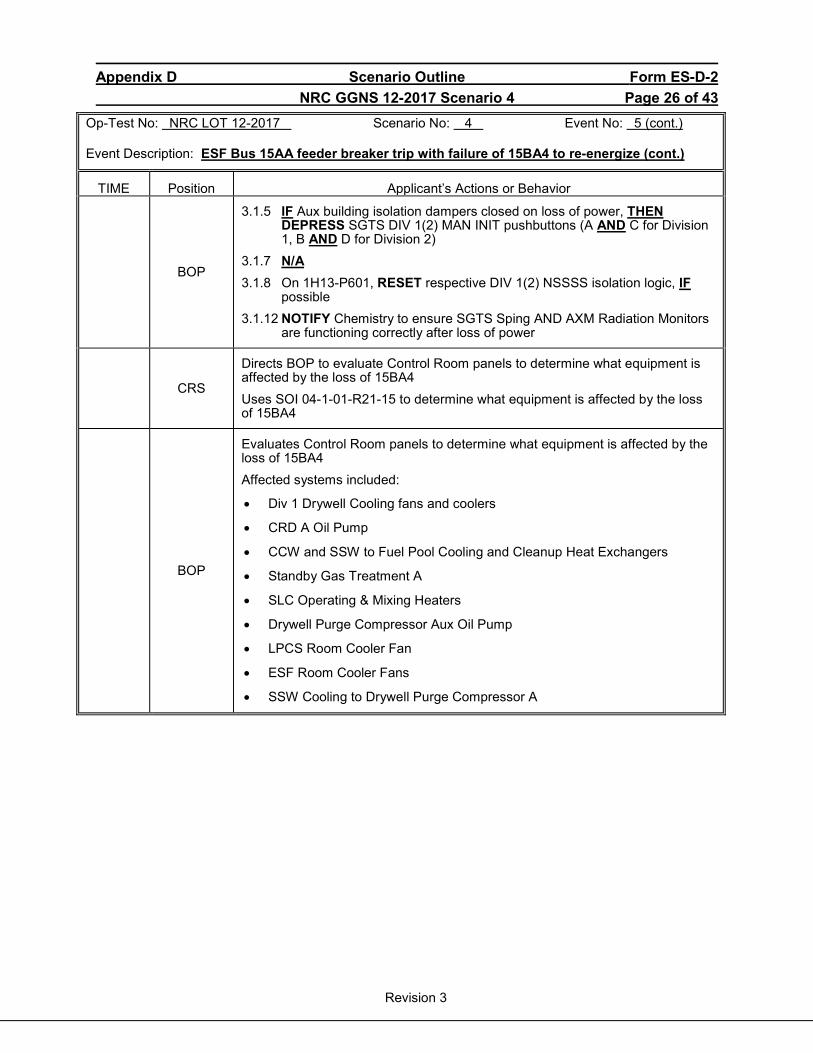
Appendix D Scenario Outline Form ES-D-2 NRC GGNS 12-2017 Scenario 4 Page 26 of 43
Revision 3
Op-Test No: NRC LOT 12-2017 Scenario No: 4 Event No: 5 (cont.) Event Description: ESF Bus 15AA feeder breaker trip with failure of 15BA4 to re-energize (cont.)
TIME Position Applicant’s Actions or Behavior
BOP
3.1.5 IF Aux building isolation dampers closed on loss of power, THEN DEPRESS SGTS DIV 1(2) MAN INIT pushbuttons (A AND C for Division 1, B AND D for Division 2)
3.1.7 N/A 3.1.8 On 1H13-P601, RESET respective DIV 1(2) NSSSS isolation logic, IF
possible 3.1.12 NOTIFY Chemistry to ensure SGTS Sping AND AXM Radiation Monitors
are functioning correctly after loss of power
CRS
Directs BOP to evaluate Control Room panels to determine what equipment is affected by the loss of 15BA4 Uses SOI 04-1-01-R21-15 to determine what equipment is affected by the loss of 15BA4
BOP
Evaluates Control Room panels to determine what equipment is affected by the loss of 15BA4 Affected systems included:
• Div 1 Drywell Cooling fans and coolers
• CRD A Oil Pump
• CCW and SSW to Fuel Pool Cooling and Cleanup Heat Exchangers
• Standby Gas Treatment A
• SLC Operating & Mixing Heaters
• Drywell Purge Compressor Aux Oil Pump
• LPCS Room Cooler Fan
• ESF Room Cooler Fans
• SSW Cooling to Drywell Purge Compressor A
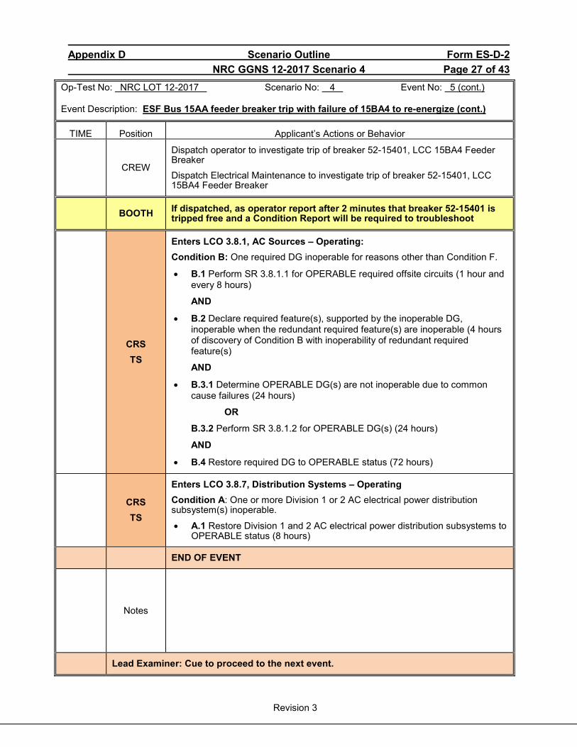
Appendix D Scenario Outline Form ES-D-2 NRC GGNS 12-2017 Scenario 4 Page 27 of 43
Revision 3
Op-Test No: NRC LOT 12-2017 Scenario No: 4 Event No: 5 (cont.) Event Description: ESF Bus 15AA feeder breaker trip with failure of 15BA4 to re-energize (cont.)
TIME Position Applicant’s Actions or Behavior
CREW
Dispatch operator to investigate trip of breaker 52-15401, LCC 15BA4 Feeder Breaker Dispatch Electrical Maintenance to investigate trip of breaker 52-15401, LCC 15BA4 Feeder Breaker
BOOTH If dispatched, as operator report after 2 minutes that breaker 52-15401 is tripped free and a Condition Report will be required to troubleshoot
CRS TS
Enters LCO 3.8.1, AC Sources – Operating: Condition B: One required DG inoperable for reasons other than Condition F.
• B.1 Perform SR 3.8.1.1 for OPERABLE required offsite circuits (1 hour and every 8 hours)
AND
• B.2 Declare required feature(s), supported by the inoperable DG, inoperable when the redundant required feature(s) are inoperable (4 hours of discovery of Condition B with inoperability of redundant required feature(s)
AND
• B.3.1 Determine OPERABLE DG(s) are not inoperable due to common cause failures (24 hours)
OR
B.3.2 Perform SR 3.8.1.2 for OPERABLE DG(s) (24 hours)
AND
• B.4 Restore required DG to OPERABLE status (72 hours)
CRS TS
Enters LCO 3.8.7, Distribution Systems – Operating Condition A: One or more Division 1 or 2 AC electrical power distribution subsystem(s) inoperable.
• A.1 Restore Division 1 and 2 AC electrical power distribution subsystems to OPERABLE status (8 hours)
END OF EVENT
Notes
Lead Examiner: Cue to proceed to the next event.

Appendix D Scenario Outline Form ES-D-2 NRC GGNS 12-2017 Scenario 4 Page 28 of 43
Revision 3
Op-Test No: NRC LOT 12-2017 Scenario No: 4 Event No: 6 Event Description: Main Steam Tunnel steam leak with failure of one steam line to isolate At the direction of the Lead Examiner, trigger Event 6 to cause a steam leak in the Aux Steam Tunnel with a failure of one steam line to isolate
TIME Position Applicant’s Actions or Behavior
BOP
Recognize and report Main Steam Tunnel high temperature
• P601-18A-A3, MSL PIPE TNL CH-B TEMP HI • P601-18A-A4, MSL PIPE TNL CH-C TEMP HI • P601-19A-A3, MSL PIPE TNL CH-A TEMP HI • P601-19A-A4, MSL PIPE TNL CH-D TEMP HI
Identifies and reports to CRS alarms are EP-4 entry condition
Reports Main Steam Tunnel temperature and trend to CRS using EP-4 Operating Guide
NOTE to Examiners: ATC may recognize rising trend on PDS computer prior to alarms.
CREW Recognize and report ‘A’ Main Steam Line failed to isolate
CRS
Enters EP-4, Auxiliary Building Control
Directs ATC to place the Mode Switch to SHUTDOWN Directs BOP to isolate the ‘A’ Main Steam Line
(CT-1) When MSIVs fail to isolate, manually scram the reactor and close the MSIVs prior to Steam Tunnel temperature exceeding 250°F (Max Safe Temperature)
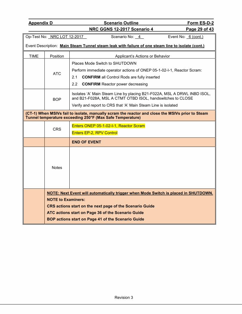
Appendix D Scenario Outline Form ES-D-2 NRC GGNS 12-2017 Scenario 4 Page 29 of 43
Revision 3
Op-Test No: NRC LOT 12-2017 Scenario No: 4 Event No: 6 (cont.) Event Description: Main Steam Tunnel steam leak with failure of one steam line to isolate (cont.)
TIME Position Applicant’s Actions or Behavior
ATC
Places Mode Switch to SHUTDOWN
Perform immediate operator actions of ONEP 05-1-02-I-1, Reactor Scram:
2.1 CONFIRM all Control Rods are fully inserted
2.2 CONFIRM Reactor power decreasing
BOP
Isolates ‘A’ Main Steam Line by placing B21-F022A, MSL A DRWL INBD ISOL, and B21-F028A, MSL A CTMT OTBD ISOL, handswitches to CLOSE
Verify and report to CRS that ‘A’ Main Steam Line is isolated
(CT-1) When MSIVs fail to isolate, manually scram the reactor and close the MSIVs prior to Steam Tunnel temperature exceeding 250°F (Max Safe Temperature)
CRS
Enters ONEP 05-1-02-I-1, Reactor Scram
Enters EP-2, RPV Control
END OF EVENT
Notes
NOTE: Next Event will automatically trigger when Mode Switch is placed in SHUTDOWN. NOTE to Examiners: CRS actions start on the next page of the Scenario Guide ATC actions start on Page 36 of the Scenario Guide BOP actions start on Page 41 of the Scenario Guide

Appendix D Scenario Outline Form ES-D-2 NRC GGNS 12-2017 Scenario 4 Page 30 of 43
Revision 3
Op-Test No: NRC LOT 12-2017 Scenario No: 4 Event No: 7 Event Description: Feedwater Line B line break inside Drywell with B21-F065B power loss When the Mode Switch is placed in SHUTDOWN, Event 7 will automatically trigger to cause a Feedwater Line B break inside the Drywell with B21-F065B power loss. (A small recirc break is also added to represent a leak downstream of the feedwater check valve)
TIME Position Applicant’s Actions or Behavior
BOP Recognize and report Feedwater Line B break inside Drywell
CREW Recognize and report high drywell pressure
CRS
Enters EP-2, RPV Control
Directs BOP to monitor and report RPV level
Directs ATC to verify high drywell pressure initiations, isolations and emergency diesel generators

Appendix D Scenario Outline Form ES-D-2 NRC GGNS 12-2017 Scenario 4 Page 31 of 43
Revision 3
Op-Test No: NRC LOT 12-2017 Scenario No: 4 Event No: 8/9 Event Description: HPCS Pump trip / LPCS logic power failure
TIME Position Applicant’s Actions or Behavior
CREW
Recognize and report HPCS Pump trip
Recognize and report LPCS Logic Power failure
Recognize and report ESF Bus 16AB lockout
CRS
Direct BOP to take actions for LPCS logic power failure IAW ARI 04-1-02-1H13-P601-21A-H8, LPCS OOSVC
Direct ATC to maximize CRD for flow
Directs I&C to install Attachment 12 for RHR
Direct ATC to restore the Auxiliary Building
CREW
Dispatch plant operator/electrical maintenance to investigate HPCS pump trip
Dispatch plant operator/electrical maintenance to investigate ESF Bus 16AB lockout
BOOTH
Role Play: If dispatched, as plant operator/electrical maintenance report after 2 minutes that HPCS pump breaker, 152-1702, is tripped and electrical maintenance is investigating If dispatched, as plant operator/electrical maintenance report after 3 minutes that ESF Bus 16AB has an overcurrent lockout and electrical maintenance is investigating When directed to install Attachment 12, trigger Event 12 and inform CRS when Attachment indicates DONE
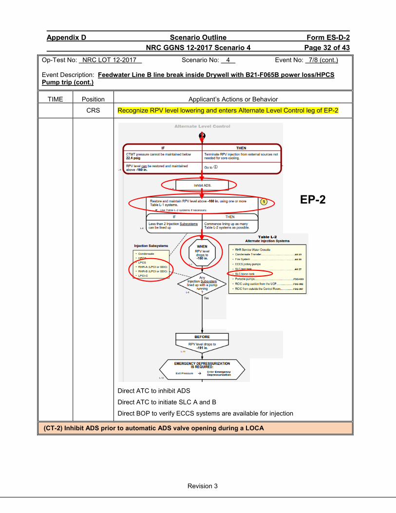
Appendix D Scenario Outline Form ES-D-2 NRC GGNS 12-2017 Scenario 4 Page 32 of 43
Revision 3
Op-Test No: NRC LOT 12-2017 Scenario No: 4 Event No: 7/8 (cont.) Event Description: Feedwater Line B line break inside Drywell with B21-F065B power loss/HPCS Pump trip (cont.)
TIME Position Applicant’s Actions or Behavior
CRS Recognize RPV level lowering and enters Alternate Level Control leg of EP-2
Direct ATC to inhibit ADS
Direct ATC to initiate SLC A and B
Direct BOP to verify ECCS systems are available for injection
(CT-2) Inhibit ADS prior to automatic ADS valve opening during a LOCA
EP-2

Appendix D Scenario Outline Form ES-D-2 NRC GGNS 12-2017 Scenario 4 Page 33 of 43
Revision 3
Op-Test No: NRC LOT 12-2017 Scenario No: 4 Event No: 7/8 (cont.) Event Description: Feedwater Line B line break inside Drywell with B21-F065B power loss / HPCS Pump trip (cont.)
TIME Position Applicant’s Actions or Behavior
CRS Directs Work Control to install Attachment 26 using HPCS piping
CRS Enters EP-3, Containment Control
CRS
Directs ATC to verify CTMT and DW hydrogen analyzers operating and energize Division 1 igniters
BOOTH
Role Play: If dispatched, as plant operator/electrical maintenance report after 2 minutes that ESF Bus 16AB is locked out on timed overcurrent. Electrical maintenance is investigating
CRS When RPV level lowers to -160 inches wide range, exits EP-2 Pressure leg and enters Emergency Depressurization leg of EP-2
EP-3
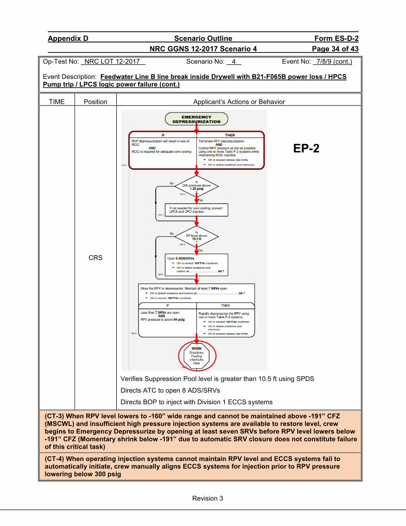
Appendix D Scenario Outline Form ES-D-2 NRC GGNS 12-2017 Scenario 4 Page 34 of 43
Revision 3
Op-Test No: NRC LOT 12-2017 Scenario No: 4 Event No: 7/8/9 (cont.) Event Description: Feedwater Line B line break inside Drywell with B21-F065B power loss / HPCS Pump trip / LPCS logic power failure (cont.)
TIME Position Applicant’s Actions or Behavior
CRS
Verifies Suppression Pool level is greater than 10.5 ft using SPDS
Directs ATC to open 8 ADS/SRVs
Directs BOP to inject with Division 1 ECCS systems
(CT-3) When RPV level lowers to -160” wide range and cannot be maintained above -191” CFZ (MSCWL) and insufficient high pressure injection systems are available to restore level, crew begins to Emergency Depressurize by opening at least seven SRVs before RPV level lowers below -191” CFZ (Momentary shrink below -191” due to automatic SRV closure does not constitute failure of this critical task)
(CT-4) When operating injection systems cannot maintain RPV level and ECCS systems fail to automatically initiate, crew manually aligns ECCS systems for injection prior to RPV pressure lowering below 300 psig
EP-2
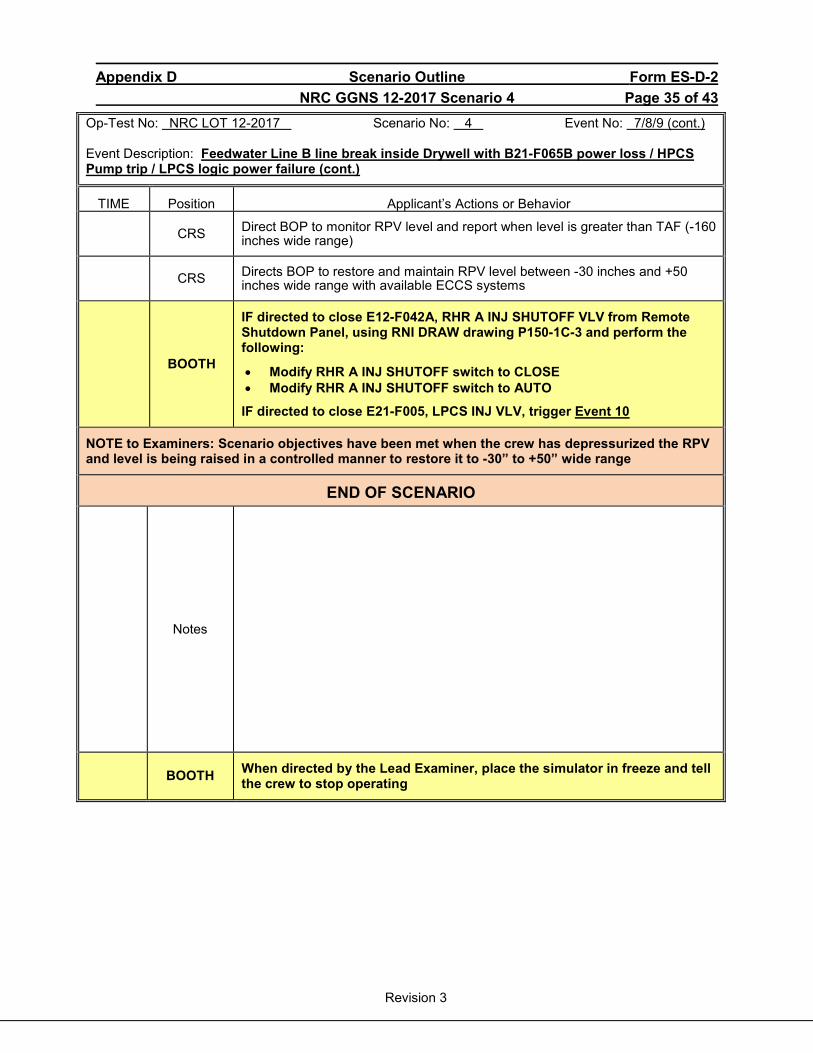
Appendix D Scenario Outline Form ES-D-2 NRC GGNS 12-2017 Scenario 4 Page 35 of 43
Revision 3
Op-Test No: NRC LOT 12-2017 Scenario No: 4 Event No: 7/8/9 (cont.) Event Description: Feedwater Line B line break inside Drywell with B21-F065B power loss / HPCS Pump trip / LPCS logic power failure (cont.)
TIME Position Applicant’s Actions or Behavior
CRS Direct BOP to monitor RPV level and report when level is greater than TAF (-160 inches wide range)
CRS Directs BOP to restore and maintain RPV level between -30 inches and +50 inches wide range with available ECCS systems
BOOTH
IF directed to close E12-F042A, RHR A INJ SHUTOFF VLV from Remote Shutdown Panel, using RNI DRAW drawing P150-1C-3 and perform the following:
• Modify RHR A INJ SHUTOFF switch to CLOSE • Modify RHR A INJ SHUTOFF switch to AUTO
IF directed to close E21-F005, LPCS INJ VLV, trigger Event 10
NOTE to Examiners: Scenario objectives have been met when the crew has depressurized the RPV and level is being raised in a controlled manner to restore it to -30” to +50” wide range
END OF SCENARIO
Notes
BOOTH When directed by the Lead Examiner, place the simulator in freeze and tell the crew to stop operating
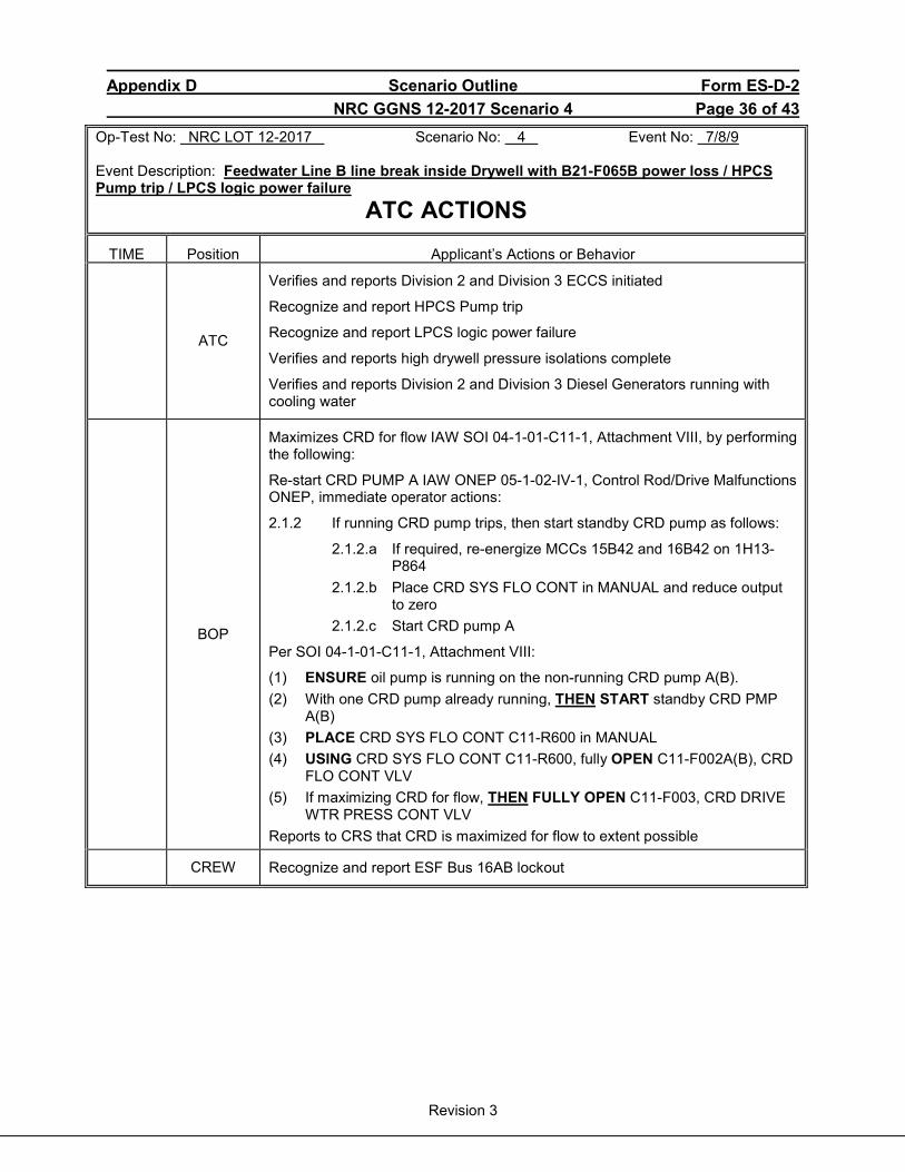
Appendix D Scenario Outline Form ES-D-2 NRC GGNS 12-2017 Scenario 4 Page 36 of 43
Revision 3
Op-Test No: NRC LOT 12-2017 Scenario No: 4 Event No: 7/8/9 Event Description: Feedwater Line B line break inside Drywell with B21-F065B power loss / HPCS Pump trip / LPCS logic power failure
ATC ACTIONS TIME Position Applicant’s Actions or Behavior
ATC
Verifies and reports Division 2 and Division 3 ECCS initiated
Recognize and report HPCS Pump trip
Recognize and report LPCS logic power failure
Verifies and reports high drywell pressure isolations complete
Verifies and reports Division 2 and Division 3 Diesel Generators running with cooling water
BOP
Maximizes CRD for flow IAW SOI 04-1-01-C11-1, Attachment VIII, by performing the following:
Re-start CRD PUMP A IAW ONEP 05-1-02-IV-1, Control Rod/Drive Malfunctions ONEP, immediate operator actions:
2.1.2 If running CRD pump trips, then start standby CRD pump as follows:
2.1.2.a If required, re-energize MCCs 15B42 and 16B42 on 1H13-P864
2.1.2.b Place CRD SYS FLO CONT in MANUAL and reduce output to zero
2.1.2.c Start CRD pump A
Per SOI 04-1-01-C11-1, Attachment VIII:
(1) ENSURE oil pump is running on the non-running CRD pump A(B). (2) With one CRD pump already running, THEN START standby CRD PMP
A(B) (3) PLACE CRD SYS FLO CONT C11-R600 in MANUAL (4) USING CRD SYS FLO CONT C11-R600, fully OPEN C11-F002A(B), CRD
FLO CONT VLV (5) If maximizing CRD for flow, THEN FULLY OPEN C11-F003, CRD DRIVE
WTR PRESS CONT VLV Reports to CRS that CRD is maximized for flow to extent possible
CREW Recognize and report ESF Bus 16AB lockout
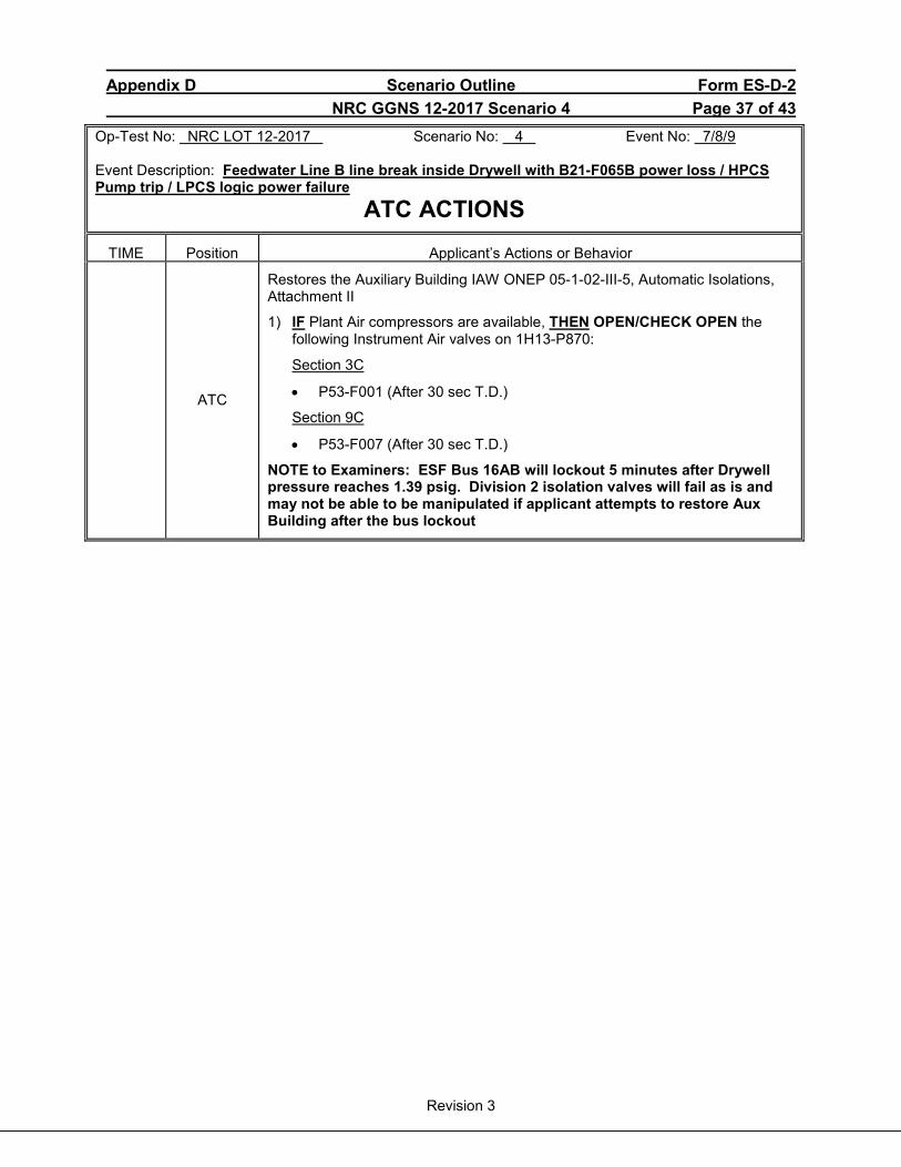
Appendix D Scenario Outline Form ES-D-2 NRC GGNS 12-2017 Scenario 4 Page 37 of 43
Revision 3
Op-Test No: NRC LOT 12-2017 Scenario No: 4 Event No: 7/8/9 Event Description: Feedwater Line B line break inside Drywell with B21-F065B power loss / HPCS Pump trip / LPCS logic power failure
ATC ACTIONS TIME Position Applicant’s Actions or Behavior
ATC
Restores the Auxiliary Building IAW ONEP 05-1-02-III-5, Automatic Isolations, Attachment II
1) IF Plant Air compressors are available, THEN OPEN/CHECK OPEN the following Instrument Air valves on 1H13-P870:
Section 3C
• P53-F001 (After 30 sec T.D.)
Section 9C
• P53-F007 (After 30 sec T.D.)
NOTE to Examiners: ESF Bus 16AB will lockout 5 minutes after Drywell pressure reaches 1.39 psig. Division 2 isolation valves will fail as is and may not be able to be manipulated if applicant attempts to restore Aux Building after the bus lockout
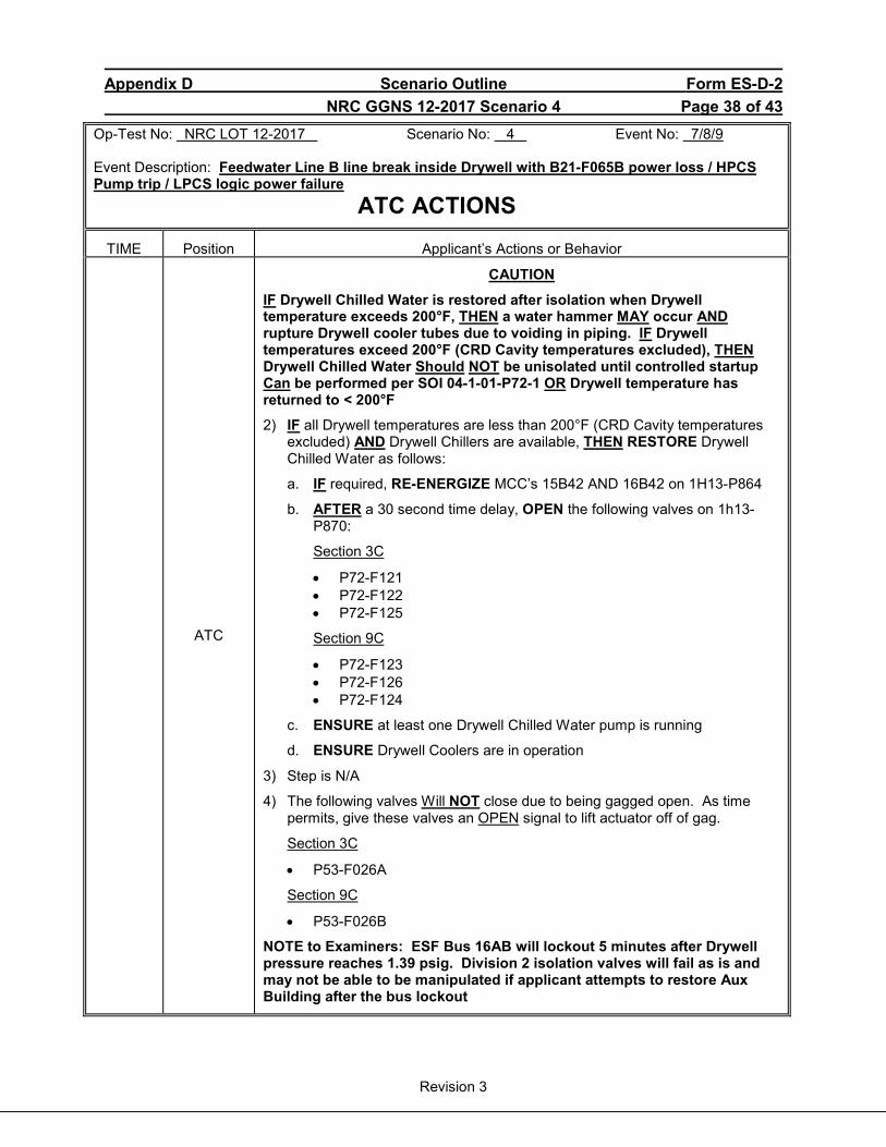
Appendix D Scenario Outline Form ES-D-2 NRC GGNS 12-2017 Scenario 4 Page 38 of 43
Revision 3
Op-Test No: NRC LOT 12-2017 Scenario No: 4 Event No: 7/8/9 Event Description: Feedwater Line B line break inside Drywell with B21-F065B power loss / HPCS Pump trip / LPCS logic power failure
ATC ACTIONS TIME Position Applicant’s Actions or Behavior
ATC
CAUTION
IF Drywell Chilled Water is restored after isolation when Drywell temperature exceeds 200°F, THEN a water hammer MAY occur AND rupture Drywell cooler tubes due to voiding in piping. IF Drywell temperatures exceed 200°F (CRD Cavity temperatures excluded), THEN Drywell Chilled Water Should NOT be unisolated until controlled startup Can be performed per SOI 04-1-01-P72-1 OR Drywell temperature has returned to < 200°F
2) IF all Drywell temperatures are less than 200°F (CRD Cavity temperatures excluded) AND Drywell Chillers are available, THEN RESTORE Drywell Chilled Water as follows:
a. IF required, RE-ENERGIZE MCC’s 15B42 AND 16B42 on 1H13-P864
b. AFTER a 30 second time delay, OPEN the following valves on 1h13-P870:
Section 3C
• P72-F121 • P72-F122 • P72-F125
Section 9C
• P72-F123 • P72-F126 • P72-F124
c. ENSURE at least one Drywell Chilled Water pump is running
d. ENSURE Drywell Coolers are in operation
3) Step is N/A
4) The following valves Will NOT close due to being gagged open. As time permits, give these valves an OPEN signal to lift actuator off of gag.
Section 3C
• P53-F026A
Section 9C
• P53-F026B
NOTE to Examiners: ESF Bus 16AB will lockout 5 minutes after Drywell pressure reaches 1.39 psig. Division 2 isolation valves will fail as is and may not be able to be manipulated if applicant attempts to restore Aux Building after the bus lockout
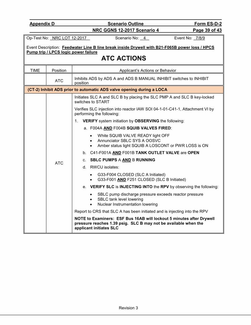
Appendix D Scenario Outline Form ES-D-2 NRC GGNS 12-2017 Scenario 4 Page 39 of 43
Revision 3
Op-Test No: NRC LOT 12-2017 Scenario No: 4 Event No: 7/8/9 Event Description: Feedwater Line B line break inside Drywell with B21-F065B power loss / HPCS Pump trip / LPCS logic power failure
ATC ACTIONS TIME Position Applicant’s Actions or Behavior
ATC Inhibits ADS by ADS A and ADS B MANUAL INHIBIT switches to INHIBIT position
(CT-2) Inhibit ADS prior to automatic ADS valve opening during a LOCA
ATC
Initiates SLC A and SLC B by placing the SLC PMP A and SLC B key-locked switches to START
Verifies SLC injection into reactor IAW SOI 04-1-01-C41-1, Attachment VI by performing the following:
1. VERIFY system initiation by OBSERVING the following:
a. F004A AND F004B SQUIB VALVES FIRED:
• White SQUIB VALVE READY light OFF • Annunciator SBLC SYS A OOSVC • Amber status light SQUIB A LOSCONT or PWR LOSS is ON
b. C41-F001A AND F001B TANK OUTLET VALVE are OPEN
c. SBLC PUMPS A AND B RUNNING
d. RWCU isolates:
• G33-F004 CLOSED (SLC A Initiated) • G33-F001 AND F251 CLOSED (SLC B Initiated)
e. VERIFY SLC is INJECTING INTO the RPV by observing the following:
• SBLC pump discharge pressure exceeds reactor pressure • SBLC tank level lowering • Nuclear Instrumentation lowering
Report to CRS that SLC A has been initiated and is injecting into the RPV
NOTE to Examiners: ESF Bus 16AB will lockout 5 minutes after Drywell pressure reaches 1.39 psig. SLC B may not be available when the applicant initiates SLC
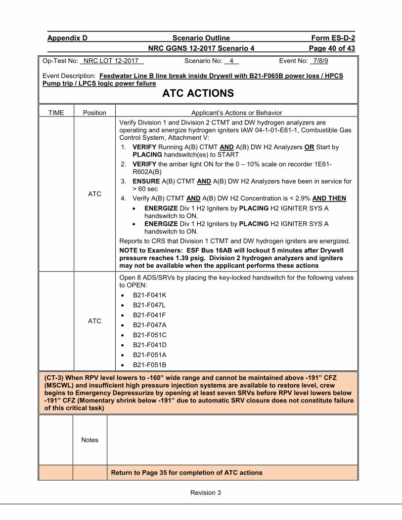
Appendix D Scenario Outline Form ES-D-2 NRC GGNS 12-2017 Scenario 4 Page 40 of 43
Revision 3
Op-Test No: NRC LOT 12-2017 Scenario No: 4 Event No: 7/8/9 Event Description: Feedwater Line B line break inside Drywell with B21-F065B power loss / HPCS Pump trip / LPCS logic power failure
ATC ACTIONS TIME Position Applicant’s Actions or Behavior
ATC
Verify Division 1 and Division 2 CTMT and DW hydrogen analyzers are operating and energize hydrogen igniters IAW 04-1-01-E61-1, Combustible Gas Control System, Attachment V: 1. VERIFY Running A(B) CTMT AND A(B) DW H2 Analyzers OR Start by
PLACING handswitch(es) to START 2. VERIFY the amber light ON for the 0 – 10% scale on recorder 1E61-
R602A(B) 3. ENSURE A(B) CTMT AND A(B) DW H2 Analyzers have been in service for
> 60 sec 4. Verify A(B) CTMT AND A(B) DW H2 Concentration is < 2.9% AND THEN
• ENERGIZE Div 1 H2 Igniters by PLACING H2 IGNITER SYS A handswitch to ON.
• ENERGIZE Div 1 H2 Igniters by PLACING H2 IGNITER SYS A handswitch to ON.
Reports to CRS that Division 1 CTMT and DW hydrogen igniters are energized. NOTE to Examiners: ESF Bus 16AB will lockout 5 minutes after Drywell pressure reaches 1.39 psig. Division 2 hydrogen analyzers and igniters may not be available when the applicant performs these actions
ATC
Open 8 ADS/SRVs by placing the key-locked handswitch for the following valves to OPEN: • B21-F041K • B21-F047L • B21-F041F • B21-F047A • B21-F051C • B21-F041D • B21-F051A • B21-F051B
(CT-3) When RPV level lowers to -160” wide range and cannot be maintained above -191” CFZ (MSCWL) and insufficient high pressure injection systems are available to restore level, crew begins to Emergency Depressurize by opening at least seven SRVs before RPV level lowers below -191” CFZ (Momentary shrink below -191” due to automatic SRV closure does not constitute failure of this critical task)
Notes
Return to Page 35 for completion of ATC actions
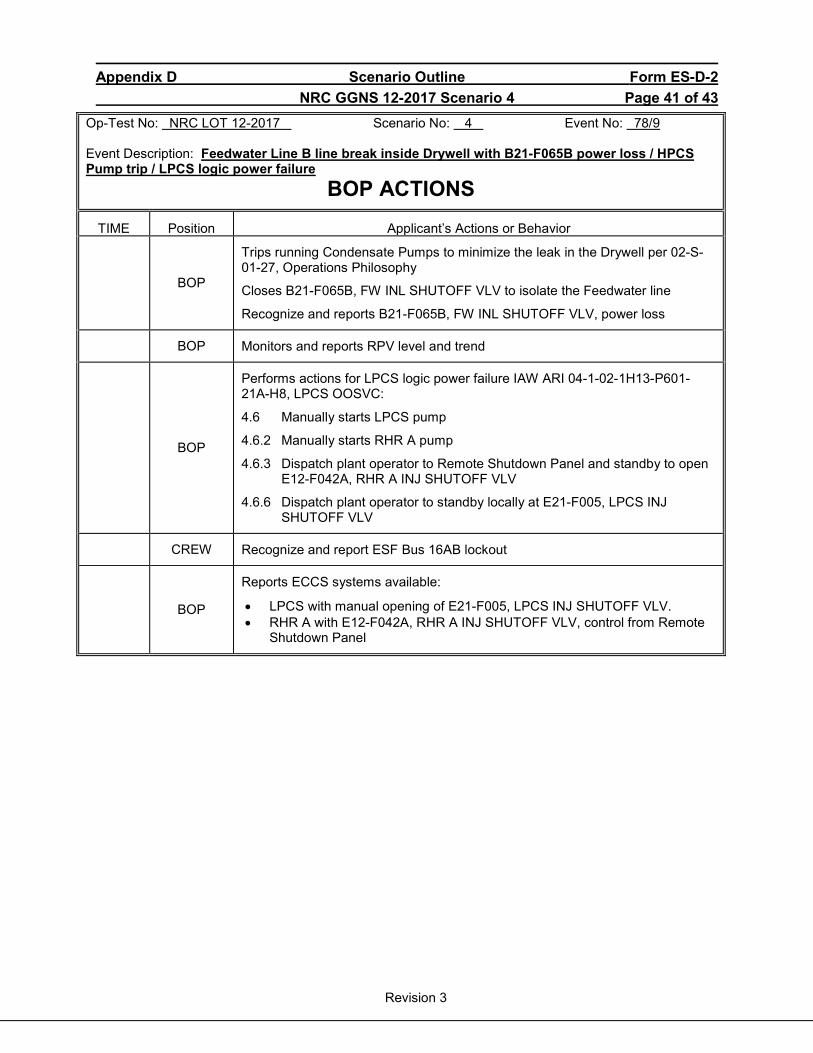
Appendix D Scenario Outline Form ES-D-2 NRC GGNS 12-2017 Scenario 4 Page 41 of 43
Revision 3
Op-Test No: NRC LOT 12-2017 Scenario No: 4 Event No: 78/9 Event Description: Feedwater Line B line break inside Drywell with B21-F065B power loss / HPCS Pump trip / LPCS logic power failure
BOP ACTIONS TIME Position Applicant’s Actions or Behavior
BOP
Trips running Condensate Pumps to minimize the leak in the Drywell per 02-S-01-27, Operations Philosophy
Closes B21-F065B, FW INL SHUTOFF VLV to isolate the Feedwater line
Recognize and reports B21-F065B, FW INL SHUTOFF VLV, power loss
BOP Monitors and reports RPV level and trend
BOP
Performs actions for LPCS logic power failure IAW ARI 04-1-02-1H13-P601-21A-H8, LPCS OOSVC:
4.6 Manually starts LPCS pump
4.6.2 Manually starts RHR A pump
4.6.3 Dispatch plant operator to Remote Shutdown Panel and standby to open E12-F042A, RHR A INJ SHUTOFF VLV
4.6.6 Dispatch plant operator to standby locally at E21-F005, LPCS INJ SHUTOFF VLV
CREW Recognize and report ESF Bus 16AB lockout
BOP
Reports ECCS systems available:
• LPCS with manual opening of E21-F005, LPCS INJ SHUTOFF VLV. • RHR A with E12-F042A, RHR A INJ SHUTOFF VLV, control from Remote
Shutdown Panel
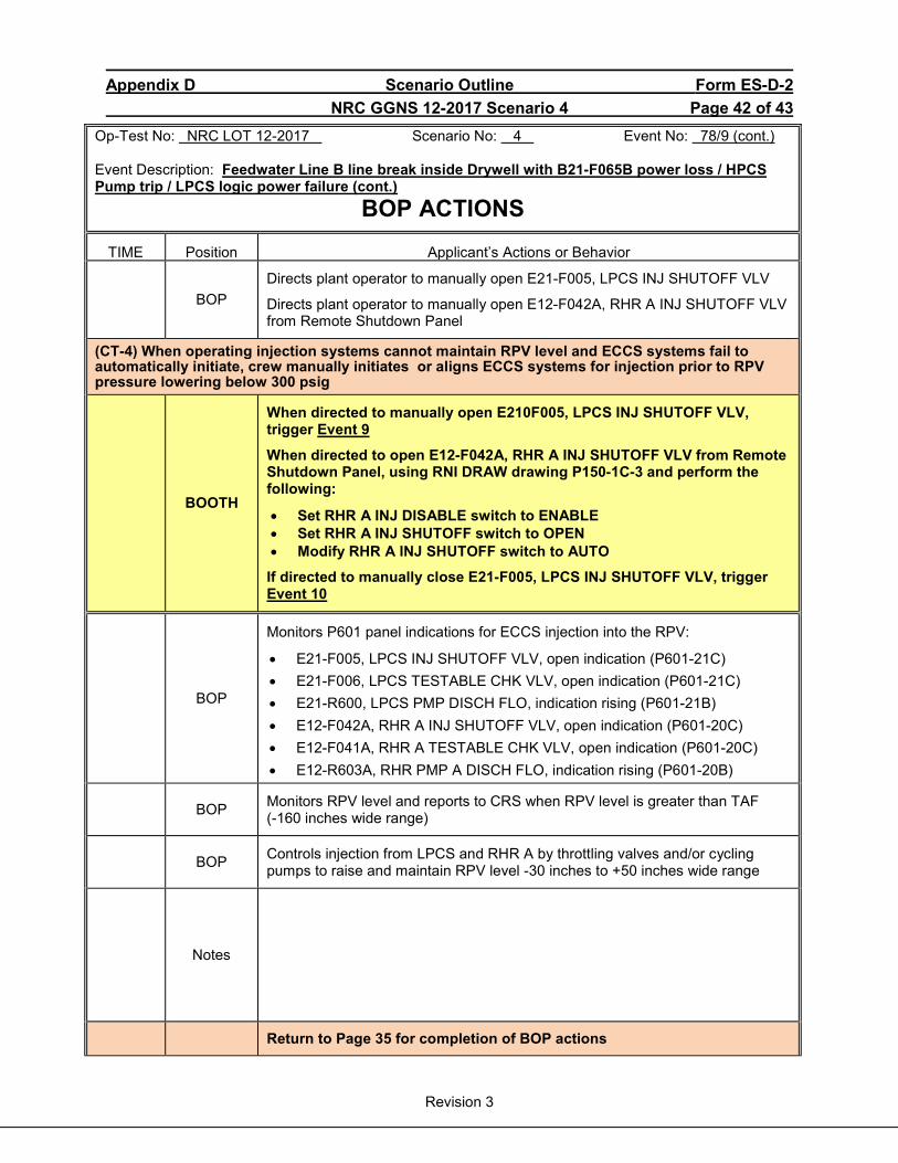
Appendix D Scenario Outline Form ES-D-2 NRC GGNS 12-2017 Scenario 4 Page 42 of 43
Revision 3
Op-Test No: NRC LOT 12-2017 Scenario No: 4 Event No: 78/9 (cont.) Event Description: Feedwater Line B line break inside Drywell with B21-F065B power loss / HPCS Pump trip / LPCS logic power failure (cont.)
BOP ACTIONS TIME Position Applicant’s Actions or Behavior
BOP
Directs plant operator to manually open E21-F005, LPCS INJ SHUTOFF VLV
Directs plant operator to manually open E12-F042A, RHR A INJ SHUTOFF VLV from Remote Shutdown Panel
(CT-4) When operating injection systems cannot maintain RPV level and ECCS systems fail to automatically initiate, crew manually initiates or aligns ECCS systems for injection prior to RPV pressure lowering below 300 psig
BOOTH
When directed to manually open E210F005, LPCS INJ SHUTOFF VLV, trigger Event 9
When directed to open E12-F042A, RHR A INJ SHUTOFF VLV from Remote Shutdown Panel, using RNI DRAW drawing P150-1C-3 and perform the following:
• Set RHR A INJ DISABLE switch to ENABLE • Set RHR A INJ SHUTOFF switch to OPEN • Modify RHR A INJ SHUTOFF switch to AUTO
If directed to manually close E21-F005, LPCS INJ SHUTOFF VLV, trigger Event 10
BOP
Monitors P601 panel indications for ECCS injection into the RPV:
• E21-F005, LPCS INJ SHUTOFF VLV, open indication (P601-21C) • E21-F006, LPCS TESTABLE CHK VLV, open indication (P601-21C) • E21-R600, LPCS PMP DISCH FLO, indication rising (P601-21B) • E12-F042A, RHR A INJ SHUTOFF VLV, open indication (P601-20C) • E12-F041A, RHR A TESTABLE CHK VLV, open indication (P601-20C) • E12-R603A, RHR PMP A DISCH FLO, indication rising (P601-20B)
BOP Monitors RPV level and reports to CRS when RPV level is greater than TAF (-160 inches wide range)
BOP Controls injection from LPCS and RHR A by throttling valves and/or cycling pumps to raise and maintain RPV level -30 inches to +50 inches wide range
Notes
Return to Page 35 for completion of BOP actions
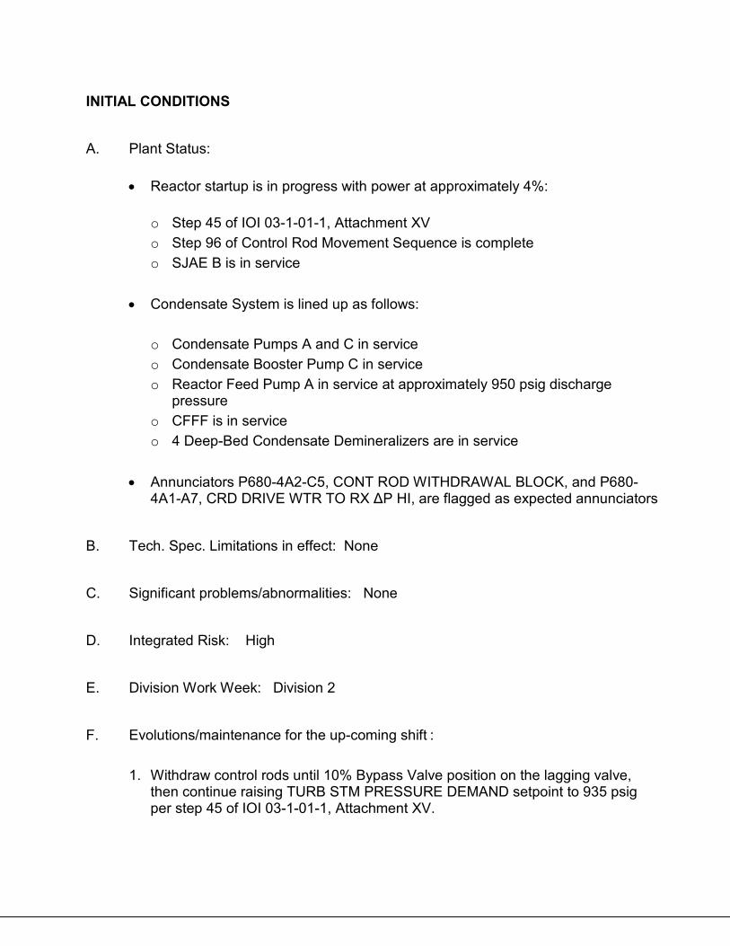
INITIAL CONDITIONS A. Plant Status:
• Reactor startup is in progress with power at approximately 4%:
o Step 45 of IOI 03-1-01-1, Attachment XV o Step 96 of Control Rod Movement Sequence is complete o SJAE B is in service
• Condensate System is lined up as follows:
o Condensate Pumps A and C in service o Condensate Booster Pump C in service o Reactor Feed Pump A in service at approximately 950 psig discharge
pressure o CFFF is in service o 4 Deep-Bed Condensate Demineralizers are in service
• Annunciators P680-4A2-C5, CONT ROD WITHDRAWAL BLOCK, and P680-
4A1-A7, CRD DRIVE WTR TO RX ΔP HI, are flagged as expected annunciators B. Tech. Spec. Limitations in effect: None C. Significant problems/abnormalities: None D. Integrated Risk: High E. Division Work Week: Division 2 F. Evolutions/maintenance for the up-coming shift :
1. Withdraw control rods until 10% Bypass Valve position on the lagging valve, then continue raising TURB STM PRESSURE DEMAND setpoint to 935 psig per step 45 of IOI 03-1-01-1, Attachment XV.
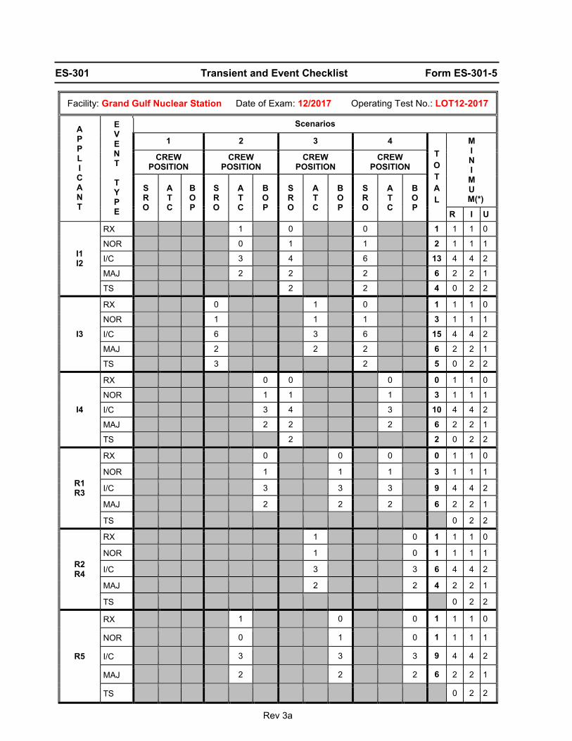
Rev 3a
ES-301 Transient and Event Checklist Form ES-301-5
Facility: Grand Gulf Nuclear Station Date of Exam: 12/2017 Operating Test No.: LOT12-2017
A P P L I C A N T
E V E N T
T Y P E
Scenarios
1 2 3 4 T O T A L
M I N I M U
M(*)
CREW POSITION
CREW POSITION
CREW POSITION
CREW POSITION
S R O
A T C
B O P
S R O
A T C
B O P
S R O
A T C
B O P
S R O
A T C
B O P
R I U
I1 I2
RX 1 0 0 1 1 1 0
NOR 0 1 1 2 1 1 1
I/C 3 4 6 13 4 4 2
MAJ 2 2 2 6 2 2 1
TS 2 2 4 0 2 2
I3
RX 0 1 0 1 1 1 0
NOR 1 1 1 3 1 1 1
I/C 6 3 6 15 4 4 2
MAJ 2 2 2 6 2 2 1
TS 3 2 5 0 2 2
I4
RX 0 0 0 0 1 1 0
NOR 1 1 1 3 1 1 1
I/C 3 4 3 10 4 4 2
MAJ 2 2 2 6 2 2 1
TS 2 2 0 2 2
R1 R3
RX 0 0 0 0 1 1 0
NOR 1 1 1 3 1 1 1
I/C 3 3 3 9 4 4 2
MAJ 2 2 2 6 2 2 1
TS 0 2 2
R2 R4
RX 1 0 1 1 1 0
NOR 1 0 1 1 1 1
I/C 3 3 6 4 4 2
MAJ 2 2 4 2 2 1
TS 0 2 2
R5
RX 1 0 0 1 1 1 0
NOR 0 1 0 1 1 1 1
I/C 3 3 3 9 4 4 2
MAJ 2 2 2 6 2 2 1
TS 0 2 2
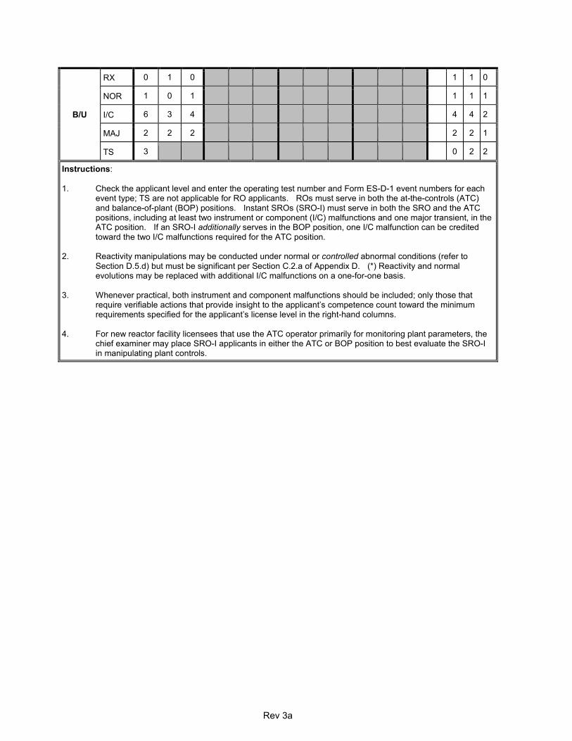
Rev 3a
B/U
RX 0 1 0 1 1 0
NOR 1 0 1 1 1 1
I/C 6 3 4 4 4 2
MAJ 2 2 2 2 2 1
TS 3 0 2 2
Instructions: 1. Check the applicant level and enter the operating test number and Form ES-D-1 event numbers for each
event type; TS are not applicable for RO applicants. ROs must serve in both the at-the-controls (ATC) and balance-of-plant (BOP) positions. Instant SROs (SRO-I) must serve in both the SRO and the ATC positions, including at least two instrument or component (I/C) malfunctions and one major transient, in the ATC position. If an SRO-I additionally serves in the BOP position, one I/C malfunction can be credited toward the two I/C malfunctions required for the ATC position.
2. Reactivity manipulations may be conducted under normal or controlled abnormal conditions (refer to
Section D.5.d) but must be significant per Section C.2.a of Appendix D. (*) Reactivity and normal evolutions may be replaced with additional I/C malfunctions on a one-for-one basis.
3. Whenever practical, both instrument and component malfunctions should be included; only those that
require verifiable actions that provide insight to the applicant’s competence count toward the minimum requirements specified for the applicant’s license level in the right-hand columns.
4. For new reactor facility licensees that use the ATC operator primarily for monitoring plant parameters, the
chief examiner may place SRO-I applicants in either the ATC or BOP position to best evaluate the SRO-I in manipulating plant controls.
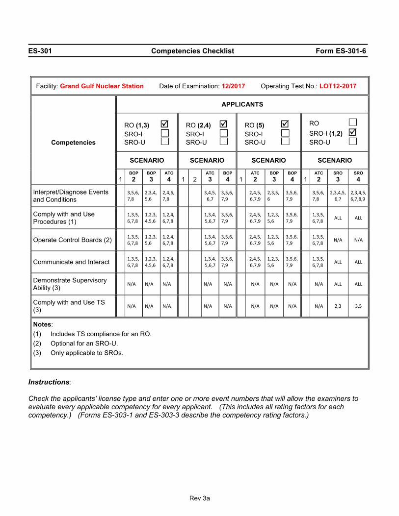
Rev 3a
ES-301 Competencies Checklist Form ES-301-6
Instructions: Check the applicants’ license type and enter one or more event numbers that will allow the examiners to evaluate every applicable competency for every applicant. (This includes all rating factors for each competency.) (Forms ES-303-1 and ES-303-3 describe the competency rating factors.)
Facility: Grand Gulf Nuclear Station Date of Examination: 12/2017 Operating Test No.: LOT12-2017
Competencies
APPLICANTS
RO (1,3) SRO-I SRO-U
RO (2,4) SRO-I SRO-U
RO (5) SRO-I SRO-U
RO SRO-I (1,2) SRO-U
SCENARIO SCENARIO SCENARIO SCENARIO
1
BOP 2
BOP 3
ATC 4
1
2
ATC 3
BOP 4
1
ATC 2
BOP 3
BOP 4
1
ATC 2
SRO 3
SRO 4
Interpret/Diagnose Events and Conditions 3,5,6,
7,8 2,3,4,5,6
2,4,6,7,8 3,4,5,
6,7 3,5,6,7,9 2,4,5,
6,7,9 2,3,5,6
3,5,6,7,9 3,5,6,
7,8 2,3,4,5,
6,7 2,3,4,5,6,7,8,9
Comply with and Use Procedures (1) 1,3,5,
6,7,8 1,2,3,4,5,6
1,2,4,6,7,8 1,3,4,
5,6,7 3,5,6,7,9 2,4,5,
6,7,9 1,2,3,5,6
3,5,6,7,9 1,3,5,
6,7,8 ALL ALL
Operate Control Boards (2) 1,3,5,6,7,8
1,2,3,5,6
1,2,4,6,7,8 1,3,4,
5,6,7 3,5,6,7,9 2,4,5,
6,7,9 1,2,3,5,6
3,5,6,7,9 1,3,5,
6,7,8 N/A N/A
Communicate and Interact 1,3,5,6,7,8
1,2,3,4,5,6
1,2,4,6,7,8 1,3,4,
5,6,7 3,5,6,7,9 2,4,5,
6,7,9 1,2,3,5,6
3,5,6,7,9 1,3,5,
6,7,8 ALL ALL
Demonstrate Supervisory Ability (3) N/A N/A N/A N/A N/A N/A N/A N/A N/A ALL ALL
Comply with and Use TS (3) N/A N/A N/A N/A N/A N/A N/A N/A N/A 2,3 3,5
Notes: (1) Includes TS compliance for an RO. (2) Optional for an SRO-U. (3) Only applicable to SROs.
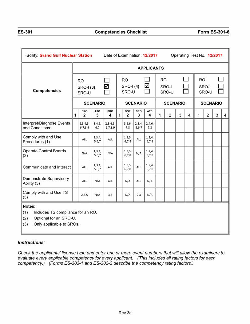
Rev 3a
ES-301 Competencies Checklist Form ES-301-6
Instructions: Check the applicants’ license type and enter one or more event numbers that will allow the examiners to evaluate every applicable competency for every applicant. (This includes all rating factors for each competency.) (Forms ES-303-1 and ES-303-3 describe the competency rating factors.)
Facility: Grand Gulf Nuclear Station Date of Examination: 12/2017 Operating Test No.: 12/2017
Competencies
APPLICANTS
RO SRO-I (3) SRO-U
RO SRO-I (4) SRO-U
RO
SRO-I SRO-U
RO
SRO-I SRO-U
SCENARIO SCENARIO SCENARIO SCENARIO
1
SRO 2
ATC 3
SRO 4
1
BOP 2
SRO 3
ATC 4
1
2
3
4
1
2
3
4
Interpret/Diagnose Events and Conditions 2,3,4,5,
6,7,8,9 3,4,5,
6,7 2,3,4,5,6,7,8,9
3,5,6,7,8
2,3,4,5,6,7
2,4,6,7,8
Comply with and Use Procedures (1) ALL 1,3,4,
5,6,7 ALL 1,3,5,6,7,8 ALL 1,2,4,
6,7,8
Operate Control Boards (2) N/A 1,3,4,
5,6,7 N/A 1,3,5,6,7,8 N/A 1,2,4,
6,7,8
Communicate and Interact ALL 1,3,4, 5,6,7 ALL
1,3,5,6,7,8 ALL 1,2,4,
6,7,8
Demonstrate Supervisory Ability (3) ALL N/A ALL N/A ALL N/A
Comply with and Use TS (3) 2,3,5 N/A 3,5 N/A 2,3 N/A
Notes: (1) Includes TS compliance for an RO. (2) Optional for an SRO-U. (3) Only applicable to SROs.