Retrofit VCB Vacuum Circuit Breakers - LSIS · Retrofit - Types and ordering information ·· 16...
48
www.lsis.com Retrofit VCB Super Solution Vacuum Circuit Breakers
Transcript of Retrofit VCB Vacuum Circuit Breakers - LSIS · Retrofit - Types and ordering information ·· 16...

www.lsis.com
Retrofit VCB
Super Solution
Super Solution
Vacuum Circuit Breakers

Susol VCB● Basic features and interrupting operation ··· 6
● Standards and certification ·························· 8
● VCB External structure ······························· 10
● Retrofit - Types and ordering information ·· 16
● Type of circuit breakers ······························ 17
● Retrofit - Ratings ········································ 18
● Retrofit - Accessories ································· 19
● Retrofit - Control circuit diagrams ·············· 29
● Retrofit - Dimensions ································· 30
● Technical data ············································ 35
● Appendix : Type of circuit breakers ··········· 42
Contents
Susol VCB is full line-up new VCB which has the high interrupting capacity, large current(~50kA, ~4000A), and maximized compatibility with existing products through the dual phases and compact sized models.

4I
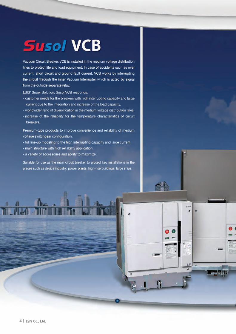
Vacuum Circuit Breaker, VCB is installed in the medium voltage distribution
lines to protect life and load equipment. In case of accidents such as over
current, short circuit and ground fault current, VCB works by interrupting
the circuit through the inner Vacuum Interrupter which is acted by signal
from the outside separate relay.
LSIS' Super Solution, Susol VCB responds.
- customer needs for the breakers with high interrupting capacity and large
current due to the integration and increase of the load capacity.
- worldwide trend of diversification in the medium voltage distribution lines.
- increase of the reliability for the temperature characteristics of circuit
breakers.
Premium-type products to improve convenience and reliability of medium
voltage switchgear configuration.
- full line-up modeling to the high interrupting capacity and large current.
- main structure with high reliability application.
- a variety of accessories and ability to maximize.
Suitable for use as the main circuit breaker to protect key installations in the
places such as device industry, power plants, high-rise buildings, large ships.

▶ Susol Retrofitted VCB provides an economical solution to the replacement and upgrading of the worn or obsolete VCB in the switchgear with minimal downtime through exacting mechanical and electrical interchangeability.
▶ Susol Retrofitted VCB features • Replacement time reduction
- Busbar replacement unnecessary- Cradle 1 : 1 compatible- Stable operation
• Switchgear life extension - Providing electrical life extension , new
standard application and certification of a equipment
• Low cost / performance / function- Large current and high breaking capacity - Accessory diversification- Minimal busbar works
•Total Solution- Technical support by LS Industrial Systems - Control circuit inspection and parts
replacement
I 5
6I
Fixed electrode
Fixed seal cup
Ceramic
Contacts
Bellows shield
Bellows
Movable electrode
Arc shield
Movable seal cup
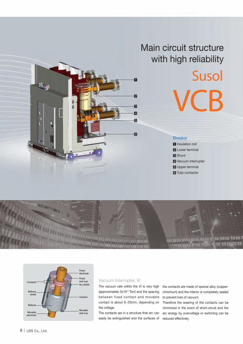
Vacuum Interrupter, VIThe vacuum rate within the VI is very high
(approximately 5x10⁻⁵ Torr) and the spacing
between f ixed contact and movable
contact is about 6~20mm, depending on
the voltage.
The contacts are in a structure that arc can
easily be extinguished and the surfaces of
the contacts are made of special alloy (copper-
chromium) and the interior is completely sealed
to prevent loss of vacuum.
Therefore the wearing of the contacts can be
minimized in the event of short-circuit and the
arc energy by overvoltage or switching can be
reduced effectively.
Main circuit structure with high reliability
VCBSusol
Breaker Insulation rod
Lower terminal
Shunt
Vacuum interrupter
Upper terminal
Tulip contactor

I 7
< < Susol VCB Series
Convenience and Variety
• Maximizing the durability and reliability of
the main circuit contactors
(Stego Tulip contactor)
• Strong structure for the temperature rise
(Natural cooling system)

8I
E2 (List 1 or List3)
E2 (List3) is first proposed in the IEC 62271-100(2008) to improve the efficiency of the interrupting test. According to it the number of interrupting test T60 is increased instead of fewer number of T10 and T30 compared to the existing List1. List3 compared with the List1 maintains the equivalent of the test but has severe test conditions because 34% higher arc energy applied to the breaker. List3 is applied to Susol VCB series.
Arc Energy: List 1 (100%) < List 2 (125%) < List 3 (134%)
100%
E2 List1 E2 List2
E2 List3 E1
125%
134%
IEC62271-100 (2002) IEC62271-100 (2008)
Acr energy applied to the breaker
Standards and certifications

I 9
< < Susol VCB Series
M2, C2
IEC standards to verify the relibilty of the product allows to select the quality level for the product to be tested according to its real performance and practical usage. The highest quality level of M2, C2 has been applied to Susol VCB.
C1, C2: Capacitive current breaking test is to verify the probability of restriking and C2 class is secured for all Susol VCB.
M1 and M2: Test to determine the mechanical durability grade
Restrike is not allowedduring “O” 24 operations
and “CO” 24 operations
•Pre-test (characteristics, isolation, and temperature)• Confirmative tests after the completion of 2000
operations (Characteristics, isolation, temperature)
•Pre-test (characteristics, isolation, and temperature)•Confirmative tests after every 2000 operation• Confirmative tests after the completion of 10,000
operations (Characteristics, isolation, temperature)
M2
M1
2,000operations2,000operations
10,000operations10,000operations
C1 C2C1 C2
M2
M1
2,000operations2,000operations
10,000operations10,000operations
2000 operation test
Sequence Control Voltage Number of operations
C - O 85% 500
C - O 100% 500
C - O 110% 500
O - CO - C 100% 250
2 restrikes are allowedduring “O” 24 operations
and “CO” 24 operations

10
External structure of VCB
Breaker ... VL type
Back side
❶ Push ON Button
❷ Push OFF Button
❸ Charge/Discharge Indicator
❹ ON/OFF Indicator
❺ Manual Charging Handle
❻ Operation Counter
❼ Interlock Lever
Name of each part
❶
❸
❹
❻
❼
❷
❺

11
Breaker ... VH type
Back side
❶ Push ON Button
❷ Push OFF Button
❸ Charge/Discharge Indicator
❹ ON/OFF Indicator
❺ Manual Changing Handle
❻ Operation Counter
❼ Interlock Lever
Name of each part
❼
❶
❸
❺
❻
❹
❷

12
Basic functions and interrupting operation
Basic functions
Manual operation① Manual Charge
a) VL type: operate the charge handle 7-8 times as a fully stroke.b) VH type: Insert the charge handle into the handle slot first. Rotate the handle clockwise 40 times more and then charge
will be complete with a click sound.- When the closing spring is charged fully "CHARGED" is displayed at the charge indicator.
② Manual closinga) Pressing the ON button the breaker is closed.b) With the closing of the breaker "ON" is displayed at Close/Trip indicator and "DISCHARGED" at the charge indicator.
③ Manual tripa) Pressing the OFF button the breaker is opened.b) "OFF" is displayed at Close/Trip indicator.
Electric operation① Electric charge
The breaker is remotely closing with charging of closing spring. If the breaker trips the closing spring is automatically charged by gear motors.
② Electric closingRemote closing is operated by the closing coil.
③ Electric tripRemote trip can be operated by the trip coil or UVT coil.
Main contacts are operated by the energy of the spring mechanism and closing spring is charged by the motor in the mechanism.Breaker is closed by closing coil and tripped by trip coil.These operations are repeated in VCB as shown in the below sequence chart.
Sequence of the switching mechanism
Motor
Closing spring
Opening spring
Closing coil
Opening coil
Main contact
Charging time of closing spring(VL type : 5 sec, VH type : 12 sec.)
Control power ON
Start closing
Closing signal
Complete closing
Start opening
Trip(Open) signal
Complete opening
Closing time Opening time

13
Basic functions and interrupting operation
The interruption of vacuum interrupters
The interruption of VCB is carried out by the vacuum interrupters.Interrupter contacts as a key part made of copper - chromium (CuCr) material with spiral shape have low contact wear characteristics and withstand voltage is excellent.Spiral contacts make the arc generated between the surfaces of contacts rotated around the surface of contact by the induced magnetic field generated due to the spiral contact structure, which results in preventing local heating, thereby corruption and interrupting instantaneously.
An example of oscillogram obtained through the interrupting test using LC resonant circuit
Fixed electrode
Fixed seal cup
Ceramic
Fixed shield
Contacts
Bellows shield
Bellows
Movable seal cup
Arc shield

14
Basic functions and interrupting operation
The interruption of vacuum interrupters
Spiral contact structure (Radial magnetic field), using the force (F = j×B) generated by the interaction of the radial magnetic field caused by the current flowing through the arc between two contacts, disperse the arc energy evenly on the surface of contact by rotating the arc that is contracted by the pinch effect so as to minimize contact damage.The images show arc behavior during the arcing time of about 8ms by shooting with high-speed camera capable of shooting 10,000 frames per sec. (0.1ms/frame) by focusing on parts of the arcing time on the above graph and simultaneously measured arc voltage also represented to show arc state by section.
In case of using the flat contactany of the designs do not reflecton when contacts are opening thearc with high temperature iscontracted and fixed in the centerof the contacts,Which is calledpinch effect.To prevent the effect two kinds ofcontact shapes are designed.One is Axial magnetic field whichspreads the arc before itscontraction, and the other isRadial magnetic field whichpermits the contraction of the arcbut makes it rotated to dispersethe energy.Because contracted arc is shapedlike a cylinder it is calledContracted arc or columnar arc.
Arc voltage waveforms and arc image captured during arcing time
Arc driving principle in the contacts of Radial magnetic field
Current
Direction of rotating arc
Columnar arc
Radial magnetic field type contact

15
Standards and certification
Susol VCB has been type tested and obtained certifications according to the latest IEC standard at international testing laboratory and can be installed and applied at the environment and conditions in accordance with the standard.
● Standard- IEC 62271-1 (2007.10)
High-voltage switchgear and controlgear - Part 1: Common specifications.- IEC 62271-100 (2008.04)
High-voltage switchgear and controlgear - Part 2: Alternating-current circuit breakers.
● Test and certification•Test report (KERI) •Test report (KEMA)

16
C1 7 8 ASA2M1 T1 U0 A
G 20M2520
Note) 1. Refer to the rating table for the product selection (Rated voltage, Breaking current, Rated current and etc.)
2. If A7(Keylock), A8(Button padlock) and AA(Lead Wire) areselected, A78A is the type name in the ordering.
3. A8 (Button Padlock) and A9 (Button Cover) can not be selected simultaneously.
4. AX (Plate for the operation of Position S/W ) is specific to the 24kV product. 5. If the existing auxiliary contacts is 5a4b or 7a7b please select 10a10b.
Retrofit - Types and ordering information
VL-06/20
Breaker
Basic model name
VL Susol VCB
Rated voltage (kV)
06 7.2
20 24
Phase distance/Compatibility
L SVB Retrofit(7.2kV)
M GVB Retrofit(7.2kV)
Version
E E type drawout
F F type drawout
G G type drawout
Motor control voltage
M0 None motormotor
M1 DC 110V
M2 DC 220V
M3 DC 125V
M4 DC 24V~30V
M5 DC 48V~60V
M6 AC 48V
M7 AC 100V~130V
M8 AC 200V~250V
Trip coil voltage
T0 None T.C
T1 DC 110V
T2 DC 220V
T3 DC 125V
T4 DC 24V~30V
T5 DC 48V~60V
T6 AC 48V
T7 AC 100V~130V
T8 AC 200V~250V
Other accessories
7 Key lock
8 Button Padlock
9 Button cover
A Lead wire
B User Plug (Part)
XPlate for the operation of Position S/W
UVT
U0 None UVT
Closing coil voltage
C0 None C.C
C1 DC 110V
C2 DC 220V
C3 DC 125V
C4 DC 24V~30V
C5 DC 48V~60V
C6 AC 48V
C7 AC 100V~130V
C8 AC 200V~250V
VL
Note) A is written only once in case of more than one.
Note) LVB became the new name of SVB and GVB after 1995.
Interrupting current (kA)
13 12.5
20 20
25 25
Rated current (A)
06 630
13 1250
20 2000
Connector and wire
SA2
Standard
A type connector, 4a4b
SA4 A type connector, 10a10b
SB2 B type connector, 4a4b
SB4 B type connector, 10a10b

17
Type of circuit breakers
Retrofit
Note) 1. Ur = Rated voltage 2. Isc = Rated short-circuit current 3. Ir = Rated normal current 4. p = Phase distance 5. All the available retrofit breakers are shown in the Appendix (42p). Please consult separately when ordering.
Ur[V] Isc[kA]Ir[A] Old VCB model name
Retrofit VCB model name Connectorp=140 p=210 SVB, GVB type LVB type
7.2
20
630
SVB-6CE-20(630A) LVB-06E-20A/06 VL-06E20L06 A
SVB-6CF-20(630A) LVB-06F-20A/06 VL-06F20L06 A
LVB-06G-20A/06 VL-06G20L06 A
1250
SVB-6CE-20(1250A) LVB-06E-20A/12 VL-06E20L13 A
SVB-6CF-20(1250A) LVB-06F-20A/12 VL-06F20L13 A
LVB-06G-20A/12 VL-06G20L13 A
25
630
SVB-6CE-25(630A) LVB-06E-25A/06 VL-06E25L06 A
SVB-6CF-25(630A) LVB-06F-25A/06 VL-06F25L06 A
LVB-06G-25A/06 VL-06G25L06 A
1250
SVB-6CE-25(1250A) LVB-06E-25A/12 VL-06E25L13 A
SVB-6CF-25(1250A) LVB-06F-25A/12 VL-06F25L13 A
LVB-06G-25A/12 VL-06G25L13 A
24
12.5
630
GVB-X/600-500/20Mf LVB-20E-13A/06 VL-20E13M06 A/B
LVB-20F-13A/06 VL-20F13M06 A/B
GVB-Y/600-500/20Mf LVB-20G-13A/06 VL-20G13M06 A/B
1250
GVB-X/1200-500/20Mf LVB-20E-13A/12 VL-20E13M13 A/B
LVB-20F-13A/12 VL-20F13M13 A/B
GVB-Y/1200-500/20Mf LVB-20G-13A/12 VL-20G1M13 A/B
25
630
GVB-X/600-1000/20Mf LVB-20E-25A/06 VL-20E25M06 A/B
LVB-20F-25A/06 VL-20F25M06 A/B
GVB-Y/600-1000/20Mf LVB-20G-25A/06 VL-20G25M06 A/B
1250
GVB-X/1200-1000/20Mf LVB-20E-25A/12 VL-20E25M13 A/B
LVB-20F-25A/12 VL-20F25M13 A/B
GVB-Y/1200-1000/20Mf LVB-20G-25A/12 VL-20G25M13 A/B
2000
GVB-X/2000-1000/20Mf LVB-20E-25A/20 VL-20E25M20 A/B
LVB-20F-25A/20 VL-20F25M20 A/B
GVB-Y/2000-1000/20Mf LVB-20G-25A/20 VL-20G25M20 A/B

18
Retrofit - Ratings
VL-06/20
* Lifetime with maintenance.
Item VL-0620/25L06/13 VL-2013M06/13 VL-2025M06/13/20Rated voltage Ur (kV) 7.2 24
Rated normal current Ir (A) 630 1250 630 1250 630 1250 2000
Rated frequency fr (Hz) 50/60
Rated short-circuit current Ise (kA) 20, 25 12.5 25
Rated short-time withstand current Ik/tk (kA/s) 20/3, 25/3 12.5/3 25/3
Rated short-circuit breaking capacity (MVA) 250/312 520 1040
Rated short-circuit making current Ip (kA) 2.5×Isc (50㎐)/2.6×Isc (60㎐)
Rated breaking time (Cycle) 3
Rated withstand voltage
Power frequency(1min) Ud(kV) 20 50
Impulse(1.2×50㎲) Up(kV) 60 125
Rated operating sequence O-0.3s-CO-15s-CO O-0.3s-CO-3min-CO
Control voltageClosing coil (V) DC 24~30V, DC 48~60V, DC 110V, DC 125V, DC 220V, AC 48V, AC 100~130V, AC220~250V
Trip coil (V) DC 24~30V, DC 48~60V, DC 110V, DC 125V, DC 220V, AC 48V, AC 100~130V, AC220~250V
Auxiliary contacts 4a4b, 10a10b
Rated opening time (sec) ≤ 0.04 ≤ 0.04
No-load closing time (sec) ≤ 0.06 ≤ 0.07
Type test class
Mechanical M2
Electrical E2 (List3)
Capacitive current switching C2
Lifetime *Mechanical (Operations) 30000
Electrical (Operations) Page 35
Installation version Drawout E, F, G type
Phase distance (mm) 140 210
Weight
Breaker (E type) (㎏) 80 82 130 136 136 136 176
Breaker (F type) (㎏) 80 82 131 138 138 138 176
Breaker (G type) (㎏) 80 82 139 142 142 142 176
Dimensions Breaker Page 30 Page 30~34
Standards IEC 62271-100(2008), KERI/KEMA, V-check(KESCO)

19
Retrofit - Accessory
MountingPosition
Type AccessorySupplied as
Remarks page7.2kV 24kV
Breaker(Internal)
M Motor ● ● Attached at the factory 20p
CC Closing Coil ● ● Attached at the factory 20p
TC Trip Coil ● ● Attached at the factory 21p
SA Auxiliary Contact 4a4b ● ● Attached at the factory 22p
(SB) Auxiliary Contact 10a10b Option Option Attached at the factory 22p
C Counter ● ● Attached at the factory 22p
A7 Keylock Option Option Attached at the factory 23p
A8 Button Padlock Option Option Attached at the factory 23p
A9 Button Cover Option Option Attached at the factory 24p
AA Lead Wire: A/B type connector Option Option Attached at the factory 24p
AB Plug/Terminal for Lead Wire Option Option Attached at the factory 25p
AX Plate for the operation of Position S/W - Option Attached at the factory 26p
Trip Coil Monitoring Contact ● ● Attached at the factory 27p
Position plate ass'y F/G Type(Stroke 310) ● Attached at the factory 26p
Position plate ass'y E Type(Stroke 250) ● Attached at the factory 26p
Breaker(External)
Compatible connector, 7.2kV, 5a4b, A-type connector(CC terminal No. 3, 4, TC terminal No. : 5.6)
Option Option 70723172194 25p
Compatible connector, 7.2kV, 10a10b, A-type connector(CC terminal No. 3, 4, TC terminal No. : 5.6)
Option Option 70723172195 25p
Compatible connector, 7.2kV, 5a4b, A-type connector(CC terminal No. 5, 6, TC terminal No. : 3.4)
Option Option 70723172196 25p
Compatible connector, 7.2kV, 10a10b, A-type connector(CC terminal No. 5, 6, TC terminal No. : 3.4)
Option Option 70723172197 25p
Compatible connector, 24kV, 4a4b, A type connector Option Option 70723172198 25p
Compatible connector, 24kV, 7a7b, A type connector Option Option 70723172199 25p
Compatible connector, 24kV, 10a10b, A type connector Option Option 70723172200 25p
Compatible connector, 24kV, 4a4b, B type connector Option Option 70723172201 25p
Compatible connector, 24kV, 7a7b, B type connector Option Option 70723172202 25p
Compatible connector, 24kV, 10a10b, B type connector Option Option 70723172203 25p
CTU Coil Test Unit Option Option - 28p
* ● : Basic Installation

20
Retrofit - Accessory
Motor: M
• Charge the closing spring of a circuit breaker by the external power source. When the charging is complete, control power of the motor will be "OFF" by the built-in Limit S/W. Without the external power source, charge manually.
Motor
VL type
Input voltage (Vn)
DC 24~ DC 48~ DC 110V DC 125V DC 220V AC 48V
AC 100~ AC 200~
30V 60V 130 250V
Load current (A) ≤ 5 ≤ 3 ≤ 1 ≤ 1 ≤ 0.5 ≤ 3 ≤ 1 ≤ 0.5
Starting current (A) 5 times of load current
Charge time Within 5 sec.
Motor
Main shaft
Charge completion contact
Gear
Note) Rated operation and control voltage range, see page 62.
Installed inside of a breaker as standard
Closing Coil: C
• It is a control device which closes a circuit breaker, when applying voltage continuously or instantaneously over 200ms to the coil control terminals.
VL type
Input voltage (Vn)
DC 24~ DC 48~ DC 110V DC 125V DC 220V AC 48V
AC 100~ AC 200~
30V 60V 130 250V
Power consumption (inrush, W) 200
Power consumption (steady, W) ≤ 5
Closing coil
Note) Rated operation and control voltage range, see page 62.
Installed inside of a breaker as standard

21
Item Susol VCB Remarks
MotorAC 85~110%
DC 85~110%
ClosingAC 85~110%
DC 85~110%
TripAC 85~110%
DC 70~110%
Applied standards IEC62271-100(2008)
Trip Coil: T
• It is a control device which trips a circuit breaker from remote place, when applying voltage continuously or instantaneously over 35ms to coil control terminals.
• When UVT coil is installed, its location is changed.
VL type
Input voltage (Vn)
DC 24~ DC 48~ DC 110V DC 125V DC 220V AC 48V
AC 100~ AC 200~
30V 60V 130 250V
Power consumption (inrush, W) 200
Power consumption (steady, W) ≤ 5
Trip coil
Note) Rated operation and control voltage range, see page 62.
Installed inside of a breaker as standard
Rated operation and control voltage range

22
Counter: C
Auxiliary Contact: SA
• It is a contact used to monitor ON/OFF status of a breaker from remote place.
• The auxiliary contacts supplied as standard configuration is 4a4b. 10a10b is also available on request.
Auxiliary contact
• It displays the total number of ON/OFF operations of a breaker.
Item VL Type
Standard 4a4b
Optional 10a10b
Retrofit - Accessory
Installed inside of a breaker as an option
Installed inside of a breaker as an option

23
Keylock: A7
• The key is to unlock the locking device first to close the breaker electrically and mechanically.
*How to operate- It is not possible to pull out the key in the unlocked
position, possible only in locked status.- Pushing "OFF" switch of a breaker turn the key
counter-clockwise to the locked position and pull it out.
- It is not possible to close the breaker electrically and mechanically in the locked position.
- Insert the key and turn clockwise and then the breaker can be closed electrically and mechanically.
Keylock
Button Padlock: A8
• It is to prevent manual operation of ON/OFF button due to user’s wrong handling.
• It is not possible to handle ON/OFF operation under the “Button lock” status.
* Key lock is not supplied.
Button Padlock
Installed inside of a breaker as an option
Installed outside of a breaker as an option

24
Button Cover: A9
• It is a protection cover to prevent an accident due to unintended operation of ON/OFF button.
• Use the push-bar to operate the ON/OFF button.
Button Cover
Lead wire: AA
• It is to connect with the control circuit of a breaker from outside. (supply wire length: 2m)
Lead wire
A type connector
B type connector
Retrofit - Accessory
Installed outside of a breaker as an option
Supplied separately from a breaker as an option
Push Bar

25
• It is connector to connect with the connector installed in the breaker. (supply connectors and terminal only for lead wire)
•Type of connector is depends on the type of connector installed in the breaker- A or B.
A type connector B type connector
Compatible connector
• It enables the old type control cables to be
connected with a new connector.
• It is required to use the existing circuit on the panel
without changing.
When ordering check the auxiliary contacts of the
existing breaker.
• In the case of 7.2kV breakers there may be two
kinds of housings that have the opposite terminal
numbers between a closing coil and a trip coil
according to the manufactred year. Please order
carefully.
* Pre-verification: Check first whether the CC terminal number is 3,4 or 5,6 to use below table.
* When ordering please use the item code according to the number of auxiliary contacts of the existing products.
Connector descriptionRated
voltageAuxiliary contact
Item code
Compatible connector, 7.2kV, 5a4b, A-type connector (CC terminal No. 3,4, TC terminal No. : 5.6)
7.2kV(VL-06)
5a4b 70723172194
Compatible connector, 7.2kV,10a10b, A-type connector (CC terminal No. 3,4, TC terminal No. : 5.6) 10a10b 70723172195
Compatible connector,7.2kV,5a4b,A-type connector (CC terminal No. 5,6, TC terminal No. : 3.4) 5a4b 70723172196
Compatible connector,7.2kV,10a10b,A-type connector (CC terminal No. 5,6, TC terminal No. : 3.4) 10a10b 70723172197
Compatible connector, 24kV, 4a4b, A-type connector
24kV(VL-20)
4a4b 70723172198
Compatible connector, 24kV, 7a7b, A-type connector 7a7b 70723172199
Compatible connector, 24kV, 10a10b, A-type connector 10a10b 70723172200
Compatible connector, 24kV, 4a4b, B-type connector 4a4b 70723172201
Compatible connector, 24kV, 7a7b, B-type connector 7a7b 70723172202
Compatible connector, 24kV, 10a10b, B-type connector 10a10b 70723172203
Plug/Terminal for lead wire Supplied separately from a breaker as an option
Installed outside the breaker as standard

26
Position Switch Plate
• It is used to operate the Position switch which is installed on the cradle.
• Applies only if a position switch is installed to the 24kV cradle.
Position S/W plate
Position plate ass'y
• A device to determine the positions of the breaker and to provide grounding function.
• It is installed on the bottom of 24kV cradle and needs to replace the existing one.
• It is supplied as standard, however, as shown below, some models may not require the replacement.
Position plate ass'y
Retrofit - Accessory
Installed outside the breaker as standard
Installed outside the breaker as standard

27
Whether or not to replace the position plate ass'y
• There ate two types of cradles for 24kV breakers according to is present in the Cradle of two kinds, depending on the manufactred year. Please referr to the table below to determine whether or not to replace the position plate ass'y
Description Position plate ass'y
Appearance
Manufactred year Until 1995 After 1995
Replacement No Yes
<Connecting terminal arrangement>
A type connector B type connector
22
23A2 10
M
MO
TOR
PO
WE
R S
OU
RC
E
N
TRIP
PO
WE
R S
OU
RC
E
A6
52a
N
CLO
SE
PO
WE
R S
OU
RC
E
A4N
A1 9
P
A5
P
A3
P
3937 5125 27 4129 43 53 5755
50
Auxiliary switch
34 36 38
4b
424026 2824
10a
4a
54 5652
Closing Spring Contact(Charge complete indicating contact)
Trip coil monitoring contact
45 4947 61
604844 46
59 71 7573
58 72 7470
10b
C
TC
CSLS2
22 424026 2824 604844 46
23 25 27 4129 43 45 4947 61
5034 36 38 54 5652 58 72 7470
3937 51 53 5755 59 71 757335
1314
1314
1413 1413
Trip coil monitoring contact: AP
• Device for monitoring the functions of the trip coils.
• To monitor the trip coils connect its terminals with the trip coil monitoring relay as shown on the circuit diagram.- If the trip coil is normal: closed-circuit consisting- If the trip coil is damaged: open circuit1) Terminals A5 and A6 monitor the trip coils in
closed position of the breaker.2) Terminal A6 and aux. contact terminal 34 monitor
the trip coils in trip position of the breaker.
• Coil Test Unit is opional, which enable monitoring the coils by connecting in parallel with the trip coil operation switch.
Installed inside of a breaker as an option
Installed outside the breaker as standard

28
Retrofit - Accessory
Coil Test Unit: CTU
• When no current flows through the coil it gives the test current which does not cause the coil to operate to check whether the coil is disconnected or not.- If the test current flows normally: coil normal- If the test current does not flow through: coil disconnected
※ As it is connected in parallel with the control part of the coil the normal operation of the coil is not affected.※ Monitoring of the running coils is not possible.※ One test unit can monitor up to two coils.
1. Input voltage: AC/DC 75V~264V
2. Contact output1) 2×a contacts for Fail indication and 2×a contacts for Alarm2) 250Vac/10A Resistive, 30Vdc/10A Resistive
3. Disconnection test cycle is 12 seconds (Test LED blinks)
4. The default operationIf Fail happens (coil disconnected), Fail LED turns on and the Fail contacts become short state.If Fail happens three times in series, Alarm LED turns on and the Alarm contacts become short state.In order to clear the Alarm status push up DIP switch on the front and then push down it (Off → On → Off)
Shunt 1
24~250V (AC/DC)
Shunt 2
AC/DC 75~264V
Fail 1
Alarm 1
Fail 2
Alarm 2
Coil
Test
Unit24~250V (AC/DC)
Input voltage
Fail (LED)Fail (RELAY)
Alarm (LED)Alarm (RELAY)
Coil Test Unit
Coil drive power(+)
Coil drive power(-)
Coil drive power
CTUInput voltage
(+)
CTUInput voltage
(+)
Coil test current
Coil
1
5
7
2
Installed outside of a breaker as an option
29
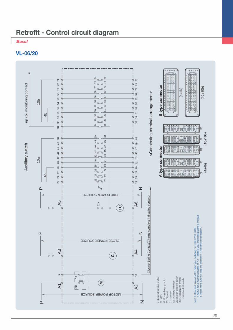
Retrofit - Control circuit diagram
VL-06/20
<Con
nect
ing
term
inal
arr
ange
men
t>
A t
ype
con
nec
tor
B t
ype
con
nec
tor
22 23A
210
M
MOTOR POWER SOURCE
N
TRIP POWER SOURCEA
6
52a
N
CLOSE POWER SOURCE
A4
N
A1
9
P
A5
P
A3
P
3937
5125
2741
2943
5357
55
50
Aux
iliar
y sw
itch
3436
38
4b
4240
2628
24
10a
4a
5456
52
Clo
sing
Spr
ing
Con
tact
(Cha
rge
com
plet
e in
dica
ting
cont
act)
Trip
coi
l mon
itorin
g co
ntac
t
4549
476160
4844
46
5971
7573
5872
7470
10b
C
TC
CS
LS2
2242
4026
2824
6048
4446
2325
2741
2943
4549
4761
5034
3638
5456
5258
7274
70
3937
5153
5755
5971
7573
35
1314
1314
1413
1413
Not
e) 1
. Clo
se a
nd T
rip c
oil i
s O
ne P
ulse
type
, exc
ludi
ng T
rip c
oil (
DC
110,
220
V)
2. A
bove
circ
uit d
iagr
am is
bas
ed o
n "O
FF"
stat
e of
VC
B a
nd c
losi
ng s
prin
g is
cha
rged
.
3. P
leas
e m
ake
sure
that
kee
p th
e di
rect
ion
of P
, N o
n th
is c
ircui
t dia
gram
.
Ø :
Exte
rnal
term
inal
of V
CB
52 :
VCB
M :
Spr
ing
char
ging
mot
orTC
: Tr
ip c
oil
C :
Clo
se c
oil
52a
: Aux
iliary
sw
itch
(a)
LS2
: Mot
or s
top
limit
switc
hC
S :
Clo
sing
spr
ing
char
ged
indi
catio
n lim
it sw
itch

30
7.2kV, 20/25kA, 630/1250AWithdrawable (F/F/G type unit, phase distance 140mm)
140
605560
83.5
450
140
673
526.5
421.5
541.5
92
375(
630A
)37
2(12
50A
)19
0
6(63
0A)
12(1
250A
)
375
24kV, 12.5kA, 630AWithdrawable (E type unit, phase distance 210mm)
608
4047
038
0
920
628.3737.5
260
480
636
981.
5
210 21010
Retrofit - Dimensions

31
24kV, 12.5kA, 630AWithdrawable (F type unit, phase distance 210mm)
470
40
210 21010
636
981.
5
480
672
920
380
628.3801.5819
88.3
24kV, 12.5kA, 630AWithdrawable (G type unit, phase distance 210mm)
480
636
981.
5
628.3
210 210
723.5
Ø35
470
380
920
853819
88.3

32
Retrofit - Dimensions
24kV, 12.5kA, 1250A 24kV, 25kA, 630/1250AWithdrawable (E type unit, phase distance 210mm)
470
210 21010
60
636
981.
5
480
608
920
380
628.3
737.5
24kV, 12.5kA, 1250A 24kV, 25kA, 630/1250AWithdrawable (F type unit, phase distance 210mm)
480
636
981.
5
628.3
210 21010
672
60
470
380
801.5
920
819
88.3

33
24kV, 25kA, 2000AWithdrawable (E type unit, phase distance 210mm)
210 21020
470
80
636
981.
5
480
608
380
628.3737.5
920
24kV, 12.5kA, 1250A 24kV, 25kA, 630/1250AWithdrawable (G type unit, phase distance 210mm)
480
636
981.
5
628.3
210 210
723.5
Ø35
470
380
920
853819
88.3

34
Retrofit - Dimensions
24kV, 25kA, 2000AWithdrawable (G type unit, phase distance 210mm)
480
636
981.
5
628.3
210 210
723.5
853
380
470
920
Ø54
819
88.3
24kV, 25kA, 2000AWithdrawable (F type unit, phase distance 210mm)
480
636
981.
5
628.3
210 21020
672
80
470
380
801.5
920
819
88.3

35
Technical data
Electrical endurance by interrupting current
7.2kV, 630/1250A, 20/25kA
Interrupting current [kA]
Interrupting current [kA]
24kV, 630A, 12.5/16kA
Num
ber[
ops.
]N
umbe
r[op
s.]
36
Technical data
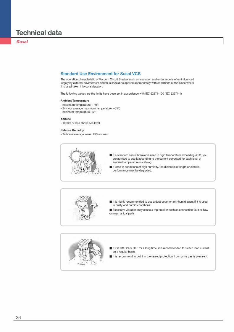
Standard Use Environment for Susol VCBThe operation characteristic of Vacuum Circuit Breaker such as insulation and endurance is often influencedlargely by external environment and thus should be applied appropriately with conditions of the place whereit is used taken into consideration.
The following values are the limits have been set in accordance with IEC 62271-100 (IEC 62271-1)
Ambient Temperature- maximum temperature: +40℃- 24-hour average maximum temperature: +35℃- minimum temperature: -5℃
Altitude- 1000m or less above sea level
Relative Humidity- 24 hours average value: 95% or less
▒ If a standard circuit breaker is used in high temperature exceeding 40℃, you are advised to use it according to the current corrected for each level of ambient temperature in catalog.
▒ If used in conditions of high humidity, the dielectric strength or electric performance may be degraded.
▒ It is highly recommended to use a dust cover or anti-humid agent if it is used in dusty and humid conditions.
▒ Excessive vibration may cause a trip breaker such as connection fault or flaw on mechanical parts.
▒ If it is left ON or OFF for a long time, it is recommended to switch load current on a regular basis.
▒ It is recommend to put it in the sealed protection if corrosive gas is prevalent.

37
Special Use Environment
The circuit breaker is designed for use in standard use environment specified in Section 2. 1 of IEC62271-1.Concerning the special use environments as below the special use conditions are required to be considered, thus please contact us in advance.
- where altitude and ambient temperature are out of standard use environment.(-40℃)- where a strong sea breeze blows- when usually used in a humid place- where a lot of steam or oil steam exists- where explosive, flammable and other harmful gases might permeate the breaker- In a dusty place- where abnormal vibration or shock exists- where a lot of ice and snow exist- other special conditions
Withstand voltage compensation according to altitudeIf the breaker is used in areas of sea level higher than 1000m the degradation of insulationperformance should be taken into consideration.
<Table 1> Criteria of withstand voltages by rated voltages specified in IEC62271-1
Up [kV/1.2 50 ]
36
2417.5127.2 60
75(82)95125
170
2028(42)38
50(65)
70
Ud [kV/1min] Ur[kV]
Power Frequency Withstand Voltage
Impulse Withstand Voltage

38
Technical data
Ex) Selecting a breaker to be used in a place of 2500m above sea level with a rated voltage 7.2kV (correction parameter 1 applied)- correction parameter at 2500m is 1.2- criteria of withstand voltage by rated voltage:
Power Frequency Withstand Voltage (Ud) = 20kV, Impulse Withstand Voltage (Up) = 60kV- requirements withstand voltage criteria:
Power Frequency Withstand Voltage (Ud) = 20×1.2 = 24kV, Impulse Withstand Voltage (Up) = 72kVTherefore rated voltage 12kV breaker shall apply to satisfy the required withstand voltage.
Ex) To apply a breaker with a rated voltage 12kV to the place of 2,500m above sea level (correction parameter 2 applied)- correction parameter at 2500m is 0.825- dielectric strength of VCB : Power Frequency Withstand Voltage (Ud) = 28×0.825 = 23.1kV,
Impulse Withstand Voltage (Up) = 75×0.825 = 62kV/1.2×50 ㎲Therefore above breaker with rated voltage 12kV shall apply to rated voltage system 7.2kV at the altitude.
<Fig.1 > withstand voltage correction parameter 1 by altitude (based on a required withstand voltage)
1
1.05
1.1
1.15
1.2
1.25
1.3
1.35
1.4
1.45
1.5
1000 1500 2000 2500 3000 3500 4000
Cor
rect
ion
para
met
er 1
Altitude (m)
<Fig.2 > withstand voltage correction parameter 2 by altitude (based on a applicable withstand voltage)
1000 1500 2000 2500 3000 3500 40000.5
0.55
0.6
0.65
0.7
0.75
0.8
0.85
0.9
0.95
1
Cor
rect
ion
para
met
er 2
Altitude (m)
Withstand voltage compensation according to altitude
Special Use Environment

39
Ia= Ir ( (Θmax - Θa)/Θr)1/2
Ia: allowable continuous current in the actual ambient temperature Θa
Ir: rated current at 40℃ ambient temperatureΘmax: acceptable overall temperature of the hottest spotΘa: the actual ambient temperature expected at -30℃ and 60℃Θr: allowable temperature in the hottest place at rated current
Ex) The calculation of the applicable load current value when a breaker with rated current2000A is used at 55℃ ambient temperatureIa = 2000×((105-55)/65)1/2 = 2000×0.87 = 1754A
<Figure 3> Allowable load current by ambient temperature
<Table 2> Allowable load current by ambient temperature
Rated current compensation in accordance with ambient temperatureWhen normal ambient temperature exceeds the temperature specified in the environmentthe following formula help to select the applicable current.
Rated current (A)
Ambient temperature (℃)
20 25 30 35 40 45 50 55 60
4000 4000 4000 4000 4000 4000 3843 3679 3508 3328
3150 3150 3150 3150 3150 3150 3026 2898 2763 2621
2000 2000 2000 2000 2000 2000 1922 1840 1754 1664
1250 1250 1250 1250 1250 1250 1201 1150 1096 1040
630 630 630 630 630 630 605 580 553 524
40
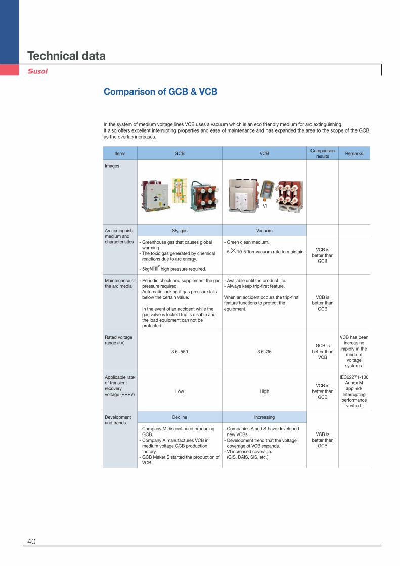
Items GCB VCBComparison
resultsRemarks
Images
Arc extinguish medium and characteristics
SF6 gas Vacuum
- Greenhouse gas that causes global warming.
- The toxic gas generated by chemical reactions due to arc energy.
- 5kgf/㎟ high pressure required.
- Green clean medium.
- 5×10⁻⁵ Torr vacuum rate to maintain. VCB is better than
GCB
Maintenance of the arc media
- Periodic check and supplement the gas pressure required.
- Automatic locking if gas pressure falls below the certain value. In the event of an accident while the gas valve is locked trip is disable and the load equipment can not be protected.
- Available until the product life.- Always keep trip-first feature.
When an accident occurs the trip-first feature functions to protect the equipment.
VCB is better than
GCB
Rated voltage range (kV)
3.6~550 3.6~36GCB is
better than VCB
VCB has been increasing
rapidly in the medium voltage
systems.
Applicable rate of transient recovery voltage (RRRV)
Low HighVCB is
better than GCB
IEC62271-100Annex M applied/
Interrupting performance
verified.
Development and trends
Decline Increasing
VCB is better than
GCB
- Company M discontinued producing GCB.
- Company A manufactures VCB in medium voltage GCB production factory.
- GCB Maker S started the production of VCB.
- Companies A and S have developed new VCBs.
- Development trend that the voltage coverage of VCB expands.
- VI increased coverage. (GIS, DAIS, SIS, etc.)
Technical data
Comparison of GCB & VCB
In the system of medium voltage lines VCB uses a vacuum which is an eco friendly medium for arc extinguishing. It also offers excellent interrupting properties and ease of maintenance and has expanded the area to the scope of the GCB as the overlap increases.
VI

41
Breaking current [kA]The fault current consists of AC and DC. Asymmetrical breaking current includes both parts and Symmetry breaking current includes only AC part.Generally the breaking current of a breaker means Symmetry breaking current
Breaking capacity [MVA]Value of prospective current that a breaker is capable of breaking at a stated voltage .Breaking capacity (MVA) = x breaking current (kA) × rated voltage (kV) ← substitute 1 for in case of single phase.
Operating duty cycleThe uniform operating cycle for use during the type tests of the circuit breaker in the short-circuit laboratory.
Item Duty Remarks
StandardO - 1min - CO - 3min - CO
O = Open, C = Close
CO = Close - Open
CO = Close - Open
CO - 15s - CO
Fast reclosingO - 0.3sec - CO - 1min - CO
O - 0.3sec - CO - 15s - CO
Breaking time [Cycle]Opening time + Arc time
Opening time [ms]Interval between the trip coil is energizing and the contacts of VI are opened
Arc time [ms]Interval between the parting of the contact and the completely interrupting of the current .
Glossary for a circuit breaker

42
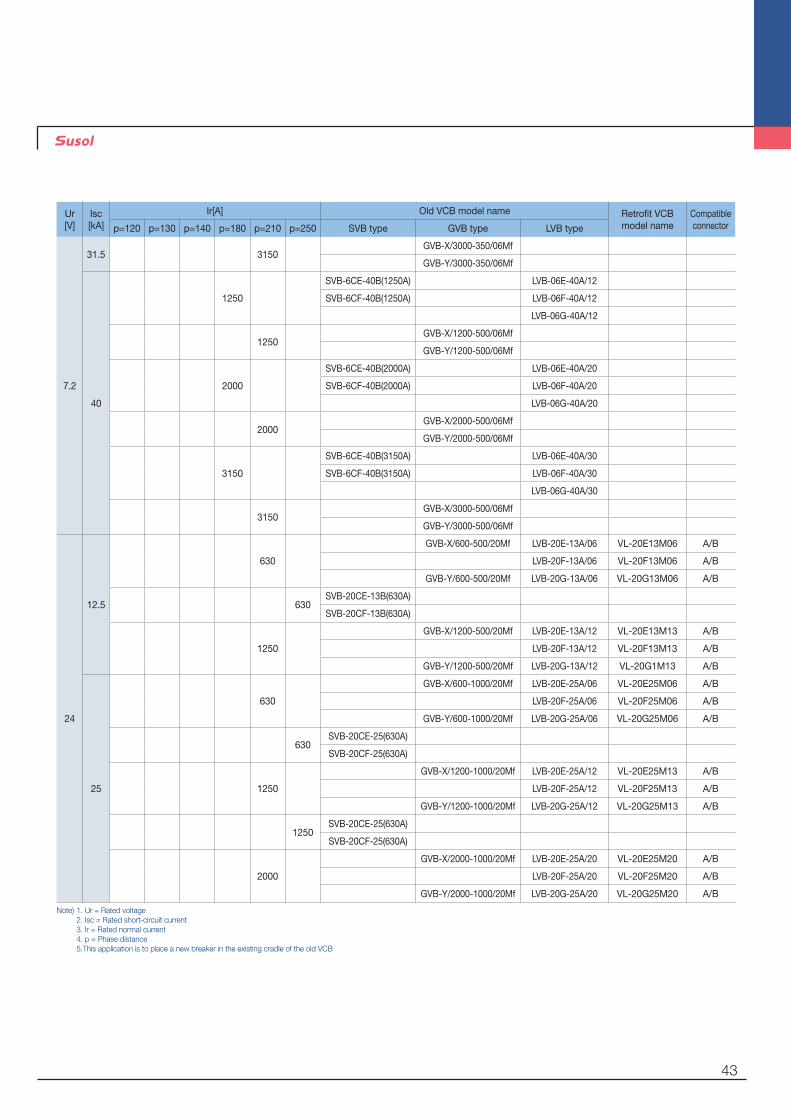
Appendix : Type of circuit breakers
Retrofit of a breaker
Ur[V]
Isc[kA]
Ir[A] Old VCB model name Retrofit VCB model name
Compatibleconnectorp=120 p=130 p=140 p=180 p=210 p=250 SVB type GVB type LVB type
7.2
8
400
SVB-6CE-8B(400A) LVB-06E-08A/04 VL-06E08B04 A
SVB-6CF-8B(400A) LVB-06F-08A/04 VL-06F08B04 A
LVB-06G-08A/04 VL-06G08B04 A
400GVB-X/400-100/06Mf
GVB-Y/400-100/06Mf
12.5
630
SVB-6CE-13(630A) LVB-06E-13A/06 VL-06E13B06 A
SVB-6CF-13(630A) LVB-06F-13A/06 VL-06F13B06 A
LVB-06G-13A/06 VL-06G13B06 A
630GVB-X/600-150/06Mf
GVB-Y/600-150/06Mf
20
630
SVB-6CE-20(630A) LVB-06E-20A/06 VL-06E20L06 A
SVB-6CF-20(630A) LVB-06F-20A/06 VL-06F20L06 A
LVB-06G-20A/06 VL-06G20L06 A
630GVB-X/600-250/06Mf
GVB-Y/600-250/06Mf LVB-06F-20R/06 A
1250
SVB-6CE-20(1250A) LVB-06E-20A/12 VL-06E20L13 A
SVB-6CF-20(1250A) LVB-06F-20A/12 VL-06F20L13 A
LVB-06G-20A/12 VL-06G20L13 A
1250GVB-X/1200-250/06Mf
GVB-Y/1200-250/06Mf LVB-06F-20R/12 A
25
630
SVB-6CE-25(630A) LVB-06E-25A/06 VL-06E25L06 A
SVB-6CF-25(630A) LVB-06F-25A/06 VL-06F25L06 A
LVB-06G-25A/06 VL-06G25L06 A
630GVB-X/600-300/06Mf
GVB-Y/600-300/06Mf LVB-06F-25R/06 A
1250
SVB-6CE-25(1250A) LVB-06E-25A/12 VL-06E25L13 A
SVB-6CF-25(1250A) LVB-06F-25A/12 VL-06F25L13 A
LVB-06G-25A/12 VL-06G25L13 A
1250GVB-X/1200-300/06Mf
GVB-Y/1200-300/06Mf LVB-06F-25R/12 A
31.5
1250
SVB-6CE-32(1250A) LVB-06E-32A/12
SVB-6CF-32(1250A) LVB-06F-32A/12
LVB-06G-32A/12
GVB-X/1200-350/06Mf
GVB-Y/1200-350/06Mf
2000
SVB-6CE-32(2000A) LVB-06E-32A/20
SVB-6CF-32(2000A) LVB-06F-32A/20
LVB-06G-32A/20
GVB-X/2000-350/06Mf
GVB-Y/2000-350/06Mf
3150
SVB-6CE-32(3150A) LVB-06E-32A/30
SVB-6CF-32(3150A) LVB-06F-32A/30
LVB-06G-32A/30
43
Ur[V]
Isc[kA]
Ir[A] Old VCB model name Retrofit VCB model name
Compatibleconnectorp=120 p=130 p=140 p=180 p=210 p=250 SVB type GVB type LVB type
7.2
31.5 3150GVB-X/3000-350/06Mf
GVB-Y/3000-350/06Mf
40
1250
SVB-6CE-40B(1250A) LVB-06E-40A/12
SVB-6CF-40B(1250A) LVB-06F-40A/12
LVB-06G-40A/12
1250GVB-X/1200-500/06Mf
GVB-Y/1200-500/06Mf
2000
SVB-6CE-40B(2000A) LVB-06E-40A/20
SVB-6CF-40B(2000A) LVB-06F-40A/20
LVB-06G-40A/20
2000GVB-X/2000-500/06Mf
GVB-Y/2000-500/06Mf
3150
SVB-6CE-40B(3150A) LVB-06E-40A/30
SVB-6CF-40B(3150A) LVB-06F-40A/30
LVB-06G-40A/30
3150GVB-X/3000-500/06Mf
GVB-Y/3000-500/06Mf
24
12.5
630
GVB-X/600-500/20Mf LVB-20E-13A/06 VL-20E13M06 A/B
LVB-20F-13A/06 VL-20F13M06 A/B
GVB-Y/600-500/20Mf LVB-20G-13A/06 VL-20G13M06 A/B
630SVB-20CE-13B(630A)
SVB-20CF-13B(630A)
1250
GVB-X/1200-500/20Mf LVB-20E-13A/12 VL-20E13M13 A/B
LVB-20F-13A/12 VL-20F13M13 A/B
GVB-Y/1200-500/20Mf LVB-20G-13A/12 VL-20G1M13 A/B
25
630
GVB-X/600-1000/20Mf LVB-20E-25A/06 VL-20E25M06 A/B
LVB-20F-25A/06 VL-20F25M06 A/B
GVB-Y/600-1000/20Mf LVB-20G-25A/06 VL-20G25M06 A/B
630SVB-20CE-25(630A)
SVB-20CF-25(630A)
1250
GVB-X/1200-1000/20Mf LVB-20E-25A/12 VL-20E25M13 A/B
LVB-20F-25A/12 VL-20F25M13 A/B
GVB-Y/1200-1000/20Mf LVB-20G-25A/12 VL-20G25M13 A/B
1250SVB-20CE-25(630A)
SVB-20CF-25(630A)
2000
GVB-X/2000-1000/20Mf LVB-20E-25A/20 VL-20E25M20 A/B
LVB-20F-25A/20 VL-20F25M20 A/B
GVB-Y/2000-1000/20Mf LVB-20G-25A/20 VL-20G25M20 A/B
Note) 1. Ur = Rated voltage 2. Isc = Rated short-circuit current 3. Ir = Rated normal current 4. p = Phase distance 5.This application is to place a new breaker in the existing cradle of the old VCB

44
Ur[V]
Isc[kA]
Ir[A] Old VCB model nameOld CRADLEmodel name
Retrofit VCBmodel name Standard VCB
model nameCompatibleconnector
p=120 p=130 p=140 p=180 p=210 p=250 SVB type GVB type LVB type LVB type Product Name
7.2
8
400
SVB-6CE-8B(400A) LVB-06E-08A/04 LCL-06E-08A/04 VCL-06E08B04 VL-06E08A04 A
SVB-6CF-8B(400A) LVB-06F-08A/04 LCL-06F-08A/04 VCL-06F08B04 VL-06F08A04 A
LVB-06G-08A/04 LCL-06G-08A/04 VCL-06G08B04 VL-06G08A04 A
400GVB-X/400-100/06Mf
GVB-Y/400-100/06Mf
12.5
630
SVB-6CE-13(630A) LVB-06E-13A/06 LCL-06E-13A/06 VCL-06E13B06 VL-06E13A06 A
SVB-6CF-13(630A) LVB-06F-13A/06 LCL-06F-13A/06 VCL-06F13B06 VL-06F13A06 A
LVB-06G-13A/06 LCL-06G-13A/06 VCL-06G13B06 VL-06G13A06 A
630GVB-X/600-150/06Mf
GVB-Y/600-150/06Mf
20
630
SVB-6CE-20(630A) LVB-06E-20A/06 LCL-06E-20A/06 VCL-06E20,25N06 VL-06E20A06 A
SVB-6CF-20(630A) LVB-06F-20A/06 LCL-06F-20A/06 VCL-06F20,25N06 VL-06F20A06 A
LVB-06G-20A/06 LCL-06G-20A/06
630
GVB-X/600-250/06MfLCL-06E-
20,25R/06-Y1VL-06E20A06 A/B
GVB-Y/600-250/06MfLCL-06F-
20,25R/06-Y2VL-06F20A06 A/B
1250
SVB-6CE-20(1250A) LVB-06E-20A/12 LCL-06E-20A/12 VCL-06E20,25N13 VL-06E20A13
SVB-6CF-20(1250A) LVB-06F-20A/12 LCL-06F-20A/12 VCL-06F20,25N13 VL-06F20A13
LVB-06G-20A/12 LCL-06G-20A/12
1250
GVB-X/1200-250/06MfLCL-06E-
20,25R/12-Y1VL-06E20A13 A/B
GVB-Y/1200-250/06MfLCL-06F-
20,25R/12-Y2VL-06F20A13 A/B
25
630
SVB-6CE-25(630A) LVB-06E-25A/06 LCL-06E-25A/06 VCL-06E20,25N06 VL-06E20A06 A
SVB-6CF-25(630A) LVB-06F-25A/06 LCL-06F-25A/06 VCL-06F20,25N06 VL-06F20A06 A
LVB-06G-25A/06 LCL-06G-25A/06
630
GVB-X/600-300/06MfLCL-06E-
20,25R/06-Y1VL-06E25A06 A/B
GVB-Y/600-300/06MfLCL-06F-
20,25R/06-Y2VL-06F25A06 A/B
1250
SVB-6CE-25(1250A) LVB-06E-25A/12 LCL-06E-25A/12 VCL-06E20,25N13 VL-06E25A13
SVB-6CF-25(1250A) LVB-06F-25A/12 LCL-06F-25A/12 VCL-06F20,25N13 VL-06F25A13
LVB-06G-25A/12 LCL-06G-25A/12
1250
GVB-X/1200-300/06MfLCL-06E-
20,25R/12-Y1VL-06E25A13 A/B
GVB-Y/1200-300/06MfLCL-06F-
20,25R/12-Y2VL-06F25A13 A/B
31.5
1250
SVB-6CE-32(1250A) LVB-06E-32A/12 LCL-06E-32A/12 VCL-06E32N13-AX VL-06E32A13 A
SVB-6CF-32(1250A) LVB-06F-32A/12 LCL-06F-32A/12 VCL-06F32N13-AX VL-06F32A13 A
LVB-06G-32A/12 LCL-06G-32A/12
GVB-X/1200-350/06Mf
GVB-Y/1200-350/06Mf
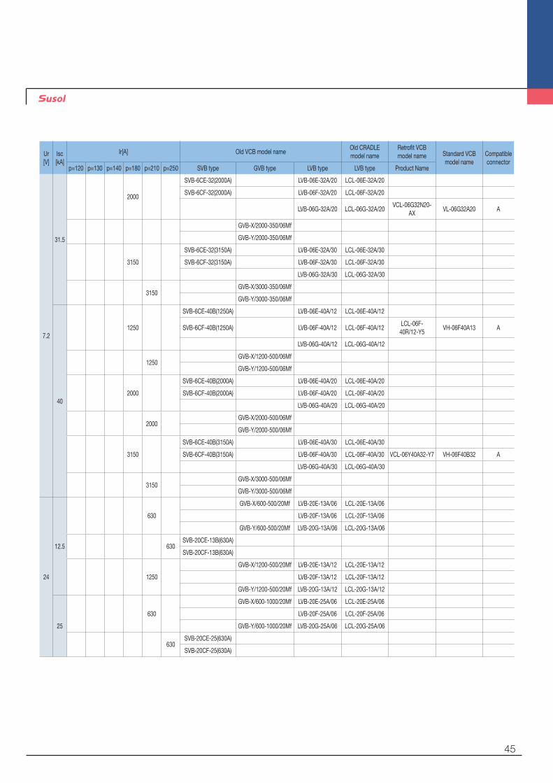
Appendix : Type of circuit breakers
Retrofit of a cradle
Note) 1. Ur = Rated voltage 2. Isc = Rated short-circuit current 3. Ir = Rated normal current 4. p = Phase distance 5. In case of replacing a breaker including the cradle please order a standard type breaker with a retrofit cradle.
45
Ur[V]
Isc[kA]
Ir[A] Old VCB model nameOld CRADLEmodel name
Retrofit VCBmodel name Standard VCB
model nameCompatibleconnector
p=120 p=130 p=140 p=180 p=210 p=250 SVB type GVB type LVB type LVB type Product Name
7.2
31.5
2000
SVB-6CE-32(2000A) LVB-06E-32A/20 LCL-06E-32A/20
SVB-6CF-32(2000A) LVB-06F-32A/20 LCL-06F-32A/20
LVB-06G-32A/20 LCL-06G-32A/20VCL-06G32N20-
AXVL-06G32A20 A
GVB-X/2000-350/06Mf
GVB-Y/2000-350/06Mf
3150
SVB-6CE-32(3150A) LVB-06E-32A/30 LCL-06E-32A/30
SVB-6CF-32(3150A) LVB-06F-32A/30 LCL-06F-32A/30
LVB-06G-32A/30 LCL-06G-32A/30
3150GVB-X/3000-350/06Mf
GVB-Y/3000-350/06Mf
40
1250
SVB-6CE-40B(1250A) LVB-06E-40A/12 LCL-06E-40A/12
SVB-6CF-40B(1250A) LVB-06F-40A/12 LCL-06F-40A/12LCL-06F-40R/12-Y5
VH-06F40A13 A
LVB-06G-40A/12 LCL-06G-40A/12
1250GVB-X/1200-500/06Mf
GVB-Y/1200-500/06Mf
2000
SVB-6CE-40B(2000A) LVB-06E-40A/20 LCL-06E-40A/20
SVB-6CF-40B(2000A) LVB-06F-40A/20 LCL-06F-40A/20
LVB-06G-40A/20 LCL-06G-40A/20
2000GVB-X/2000-500/06Mf
GVB-Y/2000-500/06Mf
3150
SVB-6CE-40B(3150A) LVB-06E-40A/30 LCL-06E-40A/30
SVB-6CF-40B(3150A) LVB-06F-40A/30 LCL-06F-40A/30 VCL-06Y40A32-Y7 VH-06F40B32 A
LVB-06G-40A/30 LCL-06G-40A/30
3150GVB-X/3000-500/06Mf
GVB-Y/3000-500/06Mf
24
12.5
630
GVB-X/600-500/20Mf LVB-20E-13A/06 LCL-20E-13A/06
LVB-20F-13A/06 LCL-20F-13A/06
GVB-Y/600-500/20Mf LVB-20G-13A/06 LCL-20G-13A/06
630SVB-20CE-13B(630A)
SVB-20CF-13B(630A)
1250
GVB-X/1200-500/20Mf LVB-20E-13A/12 LCL-20E-13A/12
LVB-20F-13A/12 LCL-20F-13A/12
GVB-Y/1200-500/20Mf LVB-20G-13A/12 LCL-20G-13A/12
25
630
GVB-X/600-1000/20Mf LVB-20E-25A/06 LCL-20E-25A/06
LVB-20F-25A/06 LCL-20F-25A/06
GVB-Y/600-1000/20Mf LVB-20G-25A/06 LCL-20G-25A/06
630SVB-20CE-25(630A)
SVB-20CF-25(630A)

46
Ur[V]
Isc[kA]
Ir[A] Old VCB model nameOld CRADLEmodel name
Retrofit VCBmodel name Standard VCB
model nameCompatibleconnector
p=120 p=130 p=140 p=180 p=210 p=250 SVB type GVB type LVB type LVB type Product Name
24 25
1250
GVB-X/1200-1000/20Mf
LVB-20E-25A/12 LCL-20E-25A/12
LVB-20F-25A/12 LCL-20F-25A/12
GVB-Y/1200-1000/20Mf
LVB-20G-25A/12 LCL-20G-25A/12
1250SVB-20CE-25(630A)
SVB-20CF-25(630A)
2000
GVB-X/2000-1000/20Mf
LVB-20E-25A/20 LCL-20E-25A/20
LVB-20F-25A/20 LCL-20F-25A/20
GVB-Y/2000-1000/20Mf
LVB-20G-25A/20 LCL-20G-25A/20
Note) 1. Ur = Rated voltage 2. Isc = Rated short-circuit current 3. Ir = Rated normal current 4. p = Phase distance 5. In case of replacing a breaker including the cradle please order a standard type breaker with a retrofit cradle.
Appendix : Type of circuit breakers
Retrofit of a cradle

47
MEMO
www.lsis.comⓒ 2011.01 LSIS Co.,Ltd. All rights reserved.
Specifications in this catalog are subject to change without notice due to continuous product development and improvement.
▒ HEAD OFFICELS-ro 127 (Hogye-dong) Dongan-gu Anyang-si Gyeonggi-do Korea Tel. (82-2)2034-4840, 4911, 4914Fax. (82-2)2034-4648
▒ CHEONG-JU PLANTCheong-Ju Plant #1, 95 Baekbong-ro Heungdeok-gu Cheongju-si Chungcheongbuk-do 361-720 Korea
2015. 01 Retrofit Vacuum Circuit Breakers(E) 2015. 01/(01) 2015. 01 Printed in Korea STAFFCOM
•LSIS USA Inc. ≫ Chicago, AmericaAddress: 2000 Millbrook Drive, Lincolnshire, Chicago, IL 60069, United States of AmericaTel: 847-941-8240 Fax: 847-941-8259 e-mail: [email protected]
•LSIS (Middle East) FZE ≫ Dubai, U.A.E.Address: LOB 19 JAFZA VIEW TOWER Room 205, Jebel Ali Freezone P.O. Box 114216, Dubai, United Arab EmiratesTel: 971 4 886 5360 Fax: 971 4 886 5361 e mail: hschoib@lsis com
•LSIS Europe B.V. ≫ Schiphol-Rijk, NetherlandsAddress: 1st. Floor, Tupolevlaan 48, 1119NZ,Schiphol-Rijk, The NetherlandsTel: 31-20-654-1420 Fax: 31-20-654-1429 e-mail: [email protected]
•LSIS-VINA Co., Ltd. ≫ Hanoi, VietnamAddress: Nguyen Khe - Dong Anh - Ha Noi - Viet NamTel: 84-4-882-0222 Fax: 84-4-882-0220 e-mail: [email protected]
•LSIS-VINA Co., Ltd. ≫ Hochiminh, VietnamAddress: 41 Nguyen Thi Minh Khai Str. Yoco Bldg 4th Floor, Hochiminh City, VietnamTel: 84-8-3822-7941 Fax: 84-8-3822-7942 e-mail: [email protected]
•LSIS Gurgaon Office ≫ Gurgaon, IndiaAddress: 109 First Floor, Park Central, Sector-30, Gurgaon- 122 002, Haryana, IndiaTel: +0091-124-493-0070 Fax: 91-1244-930-066 e-mail: [email protected]
•LSIS Japan Co., Ltd. ≫ Tokyo, JapanAddress: Toykokurakubu Bldg. 13th floor, 3-2-6, Kasumigaseki, Chiyoda-ku, Tokyo, 100-0013 JapanTEL:+81-3-6268-8241 FAX:+81-3-6268-8240 e-mail: [email protected]
•LSIS Shanghai Office ≫ Shanghai, ChinaAddress: Room 32 floors of the Great Wall Building, No. 3000 North Zhongshan Road, Putuo District, Shanghai, ChinaTel: 86-21-5237-9977 Fax: 89-21-5237-7189 e-mail: [email protected]
•LSIS Beijing Office ≫ Beijing, ChinaAddress: B-Tower 17FL.Beijing Global Trade Center B/D. No.36, BeiSanHuanDong-Lu, DongCheng-District, Beijing 100013, P.R. ChinaTel: 86-10-5825-6025,7 Fax: 86-10-5825-6026 e-mail: [email protected]
•LSIS Guangzhou Office ≫ Guangzhou, ChinaAddress: Room 1403, 14/F, New Poly Tower, No.2 Zhongshan Liu Road, Guangzhou 510180, P.R. ChinaTel: 020-8326-6754 Fax: 020-8326-6287 e-mail: [email protected]
•LSIS Chengdu Office ≫ Chengdu, ChinaAddress: Room 1701 17Floor, huamin hanjun internationnal Building, No1 Fuxing Road Chengdu, 610016, P.R. ChinaTel: 86-28-8670-3201 Fax: 86-28-8670-3203 e-mail: [email protected]
•LSIS Qingdao Office ≫ Qingdao, ChinaAddress: Room 2001,20/F,7B40, Galaxy Building, No.29 Shandong Road, Shinan District, Qingdao 266071, P.R. ChinaTel: 86-532-8501-6058 Fax: 86-532-8501-6057 e-mail: [email protected]
•LSIS (Wuxi) Co., Ltd. ≫ Wuxi, ChinaAddress: 102-A , National High & New Tech Industrial Development Area, Wuxi, Jiangsu, 214028, P.R.ChinaTel: 86-510-8534-6666 Fax: 86-510-522-4078 e-mail: [email protected]
•Dalian LSIS Co., Ltd. ≫ Dalian, ChinaAddress: No.15, Liaohexi 3-Road, Economic and Technical Development zone, Dalian 116600, ChinaTel: 86-411-8273-7777 Fax: 86-411-8730-7560 e-mail: [email protected]
▒ Global Network
•For your safety, please read user's manual thoroughly before operating.
•Contact the nearest authorized service facility for examination, repair, or adjustment.
• Please contact qualified service technician when you need maintenance. Do not disassemble or repair by yourself!
•Any maintenance and inspection shall be performed by the personnel having expertise concerned.Safety Instructions