Retaining walls in Christchurch Behaviour during, and ...
6
16 GROUND ENGINEERING February 2015 Ian Froggatt, senior geotechnical engineer, Aurecon Abstract On 4 September 2011, 22 February 2012, and 13 June 2012, Christchurch suffered major seismic events. As well as the loss of life and extensive damage to buildings that occurred, more than 2,000 retaining walls of various heights and types of construction were damaged. e damage ranged from minor movements to total collapse. e author moved to Christchurch in October 2011 to begin work at the Stronger Christchurch Infrastructure Rebuild Team (SCIRT), where the main focus of his work has been the assessment and remediation of retaining walls owned by Christchurch City Council (CCC). e type of wall has ranged from relatively low height stone facing structures which are little more than erosion protection faces, to concrete crib walls, timber pole structures and gabion and reinforced fill structures over 6m high. is paper presents the author’s observations concerning the general behaviour of, and type of damage suffered by, the walls he has inspected, some possible structural reasons for the mode of movement, the remedial solutions adopted and a summary of some measures SCIRT has adopted for specific walls in an attempt to improve seismic resilience. e paper does not discuss technical analysis or design in detail, but instead aims to cover what has been learnt from observations of retaining wall damage and provides a general overview of how retaining walls have been remediated in Christchurch. 1. Introduction At 4.35am on 4 September 2010, an earthquake with a moment magnitude of 7.1 struck the south island of New Zealand. e epicentre was close to the town of Darfield, 40km to the west of Christchurch. Since this main event there have been over 13,000 aſtershocks recorded with a moment magnitude of greater than 2.0. Two of the largest of these aſtershocks occurred on 22 February 2012 and 13 Retaining walls in Christchurch Behaviour during, and remediation after, recent earthquakes TECHNICAL PAPER FIGURE 1: CHRISTCHURCH GEOLOGY CHRISTCHURCH Christchurch Airport Lyttelton Harbour Pegasus Bay 5 km Sands and gravels Loess colluvium mixed with basalt Basaltic and pyroclastic materials covered in places by loess up to 5m thick June 2012. Because the February earthquake was centred very close to Christchurch, it was much more destructive and resulted in the deaths of 185 people and was felt from Invercargill to Wellington. ese earthquakes caused significant damage to the roading, bridges, water infrastructure and retaining wall assets owned by CCC. To repair this damage, the SCRIT was created and it is an alliance of owner participants of Canterbury Earthquake Recovery Authority (CERA), CCC, and New Zealand Transport Authority (NZTA) with non-owner participants of City Care, Downer, Fletcher, Fulton Hogan and McConnell Dowell. SCIRT’s programme of work is funded by central government and CCC. SCIRT began the design of repair work in October 2011
Transcript of Retaining walls in Christchurch Behaviour during, and ...

16 GROUND ENGINEERING February 2015
Ian Froggatt, senior geotechnical engineer, Aurecon
AbstractOn 4 September 2011, 22 February 2012, and 13 June 2012, Christchurch suffered major seismic events. As well as the loss of life and extensive damage to buildings that occurred, more than 2,000 retaining walls of various heights and types of construction were damaged. The damage ranged from minor movements to total collapse.
The author moved to Christchurch in October 2011 to begin work at the Stronger Christchurch Infrastructure Rebuild Team (SCIRT), where the main focus of his work has been the assessment and remediation of retaining walls owned by Christchurch City Council (CCC). The type of wall has ranged from relatively low height stone facing structures which are little more than erosion protection faces, to concrete crib walls, timber pole structures and gabion and reinforced fill structures over 6m high.
This paper presents the author’s observations concerning the general behaviour of, and type of damage suffered by, the walls he has inspected, some possible structural reasons for the mode of movement, the remedial solutions adopted and a summary of some measures SCIRT has adopted for specific walls in an attempt to improve seismic resilience.
The paper does not discuss technical analysis or design in detail, but instead aims to cover what has been learnt from observations of retaining wall damage and provides a general overview of how retaining walls have been remediated in Christchurch.
1. IntroductionAt 4.35am on 4 September 2010, an earthquake with a moment magnitude of 7.1 struck the south island of New Zealand. The epicentre was close to the town of Darfield, 40km to the west of Christchurch. Since this main event there have been over 13,000 aftershocks recorded with a moment magnitude of greater than 2.0. Two of the largest of these aftershocks occurred on 22 February 2012 and 13
Retaining walls in Christchurch Behaviour during, and remediation after, recent earthquakes
TECHNICAL PAPER
F I G U R E 1 : C H R I S T C H U R C H G E O L O G Y
CHRISTCHURCH
ChristchurchAirport
Lyttelton Harbour
Pegasus Bay
5 km
Sands and gravels
Loess colluvium mixedwith basalt
Basaltic and pyroclasticmaterials covered in placesby loess up to 5m thick
June 2012. Because the February earthquake was centred very close to Christchurch, it was much more destructive and resulted in the deaths of 185 people and was felt from Invercargill to Wellington.
These earthquakes caused significant damage to the roading, bridges, water infrastructure and retaining wall assets owned by CCC. To repair this damage, the SCRIT was created and it is an alliance of owner participants of Canterbury Earthquake Recovery Authority (CERA), CCC, and New Zealand Transport Authority (NZTA) with non-owner participants of City Care, Downer, Fletcher, Fulton Hogan and McConnell Dowell. SCIRT’s programme of work is funded by central government and CCC.
SCIRT began the design of repair work in October 2011

February 2015 GROUND ENGINEERING 17
and the repair programme is scheduled to run until the end of 2016. The initial SCIRT works programme included over 600 retaining walls, and it is this element of SCIRT’s programme that has formed the bulk of the author’s work since October 2011. At the time of writing, the estimated value of physical work in the whole of the SCIRT programme was approximately NZD$1.6bn (£793M) and 160 projects with a value of approximately NZD$614M (£304M) were at design stage.
The author has led one of four geotechnical teams within SCIRT since October 2011, with the main focus being remediation of retaining walls. It is on experience gained during this period that the author has drawn on for the content of this paper.
Although some typically observed failure modes are discussed below, it is also worth noting that there have been many examples of each wall type that have suffered negligible to nil earthquake damage, despite being located in areas that suffered relatively large accelerations. It has certainly not been easy to provide ready explanations for this apparently anomalous behaviour. One explanation that has been suggested is that the direction of maximum acceleration relative to the orientation of the retaining wall may have governed the degree of damage suffered. Q
Figure 2 Typical undamaged stone facing wall (above left) and typical damage suffered (left)
A detailed examination of the reasons for highly variable degrees of damage in similar wall types is beyond the scope of this paper, but would certainly form a suitable subject for further study.
2. Overview of Christchurch geology and typical geology in the location of the retaining wallsFigure 1 shows an extract from the 1:250,000 Christchurch Geology Map (Forsyth et al, 2008). The northerly, lighter areas of the map represent a relatively flat area at the eastern edge of the Canterbury Plains which are an aggrading gravel outwash feature. The Christchurch central business district (CBD) and much of suburban Christchurch is situated here. Gravels, sands and silts dominate the geology of the plains. The darker, arc shaped region to the south represents the Port Hills area, an elevated zone where many of the retaining walls remediated by SCIRT are located.
The Christchurch CBD itself is located on alluvial sand and silt deposits (Brown and Weeber, 1992). These deposits overlie dune and beach deposits of the Christchurch Formation, which in turn overlie the Riccarton Gravels Formation. The Riccarton Gravels are the shallowest of the numerous artesian aquifers present beneath Christchurch, and being commonly dense to very dense, usually represent the deepest geological layer of interest to most geotechnical engineers.
The geology of the Port Hills area of Christchurch is governed by the presence of five extinct volcanoes. In this area, typically, basalt and other pyroclastic flow materials are overlain by windblown loess. At the lower levels of the slopes, the loess often occurs as a colluvium mixed with sands and gravels of basalt and pyroclastic materials. The majority of the retaining walls in Christchurch and of those examined by the author are located within this Port Hills area.
3. Typical retaining wall behaviour, damage suffered and remedial solutions adopted3.1 “Non-engineered” stone wallsThis type of structure is referred to here as “non-engineered” as it is likely that no formal design was carried out prior to construction of these walls. The majority of these structures were used to face loess cuttings and as such serve as little more than erosion protection features for the loess behind. A typical height for these structures is less than 3m but some are over 4m. They are mostly constructed from basalt blocks, a readily available local material.
Many of these stone facing structures are to be found in the Lyttelton and Cashmere areas of Christchurch. Figure 2 shows an undamaged stone facing wall and also provides an example of the typical type of earthquake damage suffered. This includes a falling away of large panels of blockwork, often from higher levels, with other panels either partially displaced from the cutting or unmoved.
During inspections carried out by SCIRT, it has often been observed that where stone facing structures have collapsed, they have exposed near vertical faces of intact loess. This indicated that the insitu loess, provided it is

18 GROUND ENGINEERING February 2015
kept undisturbed and dry, can be expected to have a high apparent cohesion under short term loading. This is an observation also recorded by the Ministry of Business Innovation and Employment (MBIE) (2014).
In Lyttelton, many of the collapsed stone facings had heritage significance and therefore a key priority for the repair of these walls has been to allow provision for the stone facing to be reinstated. While SCIRT’s responsibility is to make the wall structurally sound, CCC and the Historic Places Trust will decide on the future facing of the walls (Stronger Christchurch Infrastructure Rebuild Team website, July 2014). To provide a seismically resilient repair, and to allow for the future replacement of the blocks, a soil nailed and concrete facing solution has been adopted in many cases. A sloped face and outstand base are included to receive the blocks at a future date. Figure 3 provides a simplified concept sketch and constructed photograph of this type of solution.
TECHNICAL PAPER
F I G U R E 3 : C O N C E P T S K E T C H O FS O I L N A I L A N D C O N C R E T E F A C E W A L L S O L U T I O N
Anchors/nails(length as per design)
Granular fillGranular fillCast inplace wall
Outstandto receive
block facing
Figure 3 Concept sketch of soil nail and concrete face solution (left) and post-construction photograph (below left)
Figure 4 Views of earthquake damage of a crib wall in Lyttelton. Above right shows fill loss from the face of the wall and right shows severe road slumping above the wall
3.2 Concrete crib wallsThere are many hundreds of metres of concrete crib walling in Christchurch, much of which was built in the 1980s and 1990s. Although a form of “engineered” wall, none of the presently existing concrete crib walling would have been designed to the seismic standards required of present day Christchurch. Like the stone facings discussed above, the behaviour of concrete crib walls was highly variable and anomalous. Some crib walls suffered extreme damage and others remained undamaged completely. Figure 4 shows significant damage to an up to 4.5m high wall on Cunningham Terrace in Lyttelton. These photos were taken on 3 February 2012.
The following observations are made concerning the mode of failure and the damage suffered:n The concrete crib units (called “headers” and “stretchers”) are not mechanically connected when constructed. It has therefore been suggested that a likely
P

February 2015 GROUND ENGINEERING 19
cause of failure was that the combination of vertical and horizontal acceleration pulses caused the individual units to progressively “jump” forward, causing the bulging seen in the upper photo of Figure 4.n This photo also shows that the wall has lost a significant amount of fill. This is likely due to the fill being rounded greywacke river gravels (a material which is readily available in Christchurch) which is difficult to compact and, critically, much smaller than the frontal voids in the crib units, allowing it to be easily shaken out of the wall.n The lower photo in Figure 4 shows the devastating effect of the forward bulging and loss of fill on the road above. The bowing of the previously straight handrail also provides some indication of the degree of movement suffered. Such movement, as well as causing a road closure, can also obviously have serious effects on services. Stormwater and sewer pipes have been cracked by such movements, posing risks to public health.n During reconstruction, the significant “step” in the road was shown during construction to match very well with the position of the interface between the retaining wall backfill and the insitu loess material the wall was filled against. This was further evidence of the observation discussed in Section 3.1 that intact dry loess can have a high apparent cohesion under short term loading.
Although the author has carried out no formal study into the subject, it is worth noting that where crib walls have been heavily vegetated, possibly caused by lack of maintenance or the establishment of an invasive species, they appear to have suffered less movement and fill loss as a result. Many such heavily vegetated walls often appear to have suffered little or no damage compared to nearby crib walls which had sparse vegetation cover. This observation has also been recorded by the MBIE in its recently published design guide aimed at residential walls in Christchurch (MBIE, July 2014).
Three methods of remediation of concrete crib walls employed by SCIRT, in order of cost and degree of modification, are:n Where a crib wall is in reasonable condition with low levels of damage, placement of concrete into the voids of the front of the crib wall to prevent further fill loss and help connect the individual units.n Where the crib wall has suffered some forward movement but is still largely intact, the drilling of anchors through the wall and the casting of a reinforced concrete face to the front of the wall.n Where the degree of damage suffered represents complete failure, and a new wall is required (such as the damage shown in Figure 4), the construction of an anchored steel king post and reinforced concrete panel wall. A simplified concept sketch of such a solution is shown in Figure 5. This was the solution employed to rebuild the Cunningham Terrace wall.
A detailed review of the design of the solution shown in Figure 5 is outside the scope of this paper. However, a brief summary of key details is as follows:• The design life required was 100 years.• Typically, 32mm diameter steel anchor bars were used.• Where anchors have been installed into loess
F I G U R E 5 : S I M P L I F I E D C O N C E P T S K E T C H O FA N C H O R E D K I N G P O S T R E T A I N I N G W A L L S O L U T I O N
Impact barrier
Steel king postswith precastconcreteinfill panels
Granular fillGranular fill
Socket length governed bygeology and wall height
Drilled and groutedsteel anchors(anchor bondedlength)
Figure 5 Simplified concept sketch of the form of anchored king post solution employed by SCIRT
Figure 6 Finished anchored king post retaining walls used to replace collapsed concrete crib walls at Cunningham Terrace in Lyttelton (above right) and Maffeys Road (right) in Mount Pleasant, Christchurch. Each of the steel “hats” covers the head of an anchorQ
20 GROUND ENGINEERING February 2015
TECHNICAL PAPER
material, they have extended up to 12m back from the wall face.• The working load required from the anchors has varied from 45kN to 100kN, dependent on wall height and the number of rows of anchors.• The steel king posts have typically consisted of 25UCx90 sections embedded 3m in a 500mm diameter concreted socket, installed at 2.5 spacings.• The diameter of the drilled hole for the anchors was 150mm.• The height of the concrete lagging panels varied to suit the geometry, but each was 175mm wide and 2,440mm long.
Figure 6 shows a view of the finished anchored king post solutions at Cunningham Terrace and another site at Maffeys Road, where a crib wall collapse was remediated with a similar solution.
3.3 Mechanically stabilised earth (MSE) wallsFor the purposes of this paper, mechanically stabilised earth walls refers to structures consisting of gabion baskets with mesh reinforcing panels extending backwards from the gabions. A view of the front face of this type of structure is shown in Figure 7. Many of these walls exist in the Port Hills area of Christchurch. They have been built up to 6m high and often provide support to residential roads. Due to the relatively simple and economic build process, many developers have used this type of wall to overcome level differences when creating subdivisions.
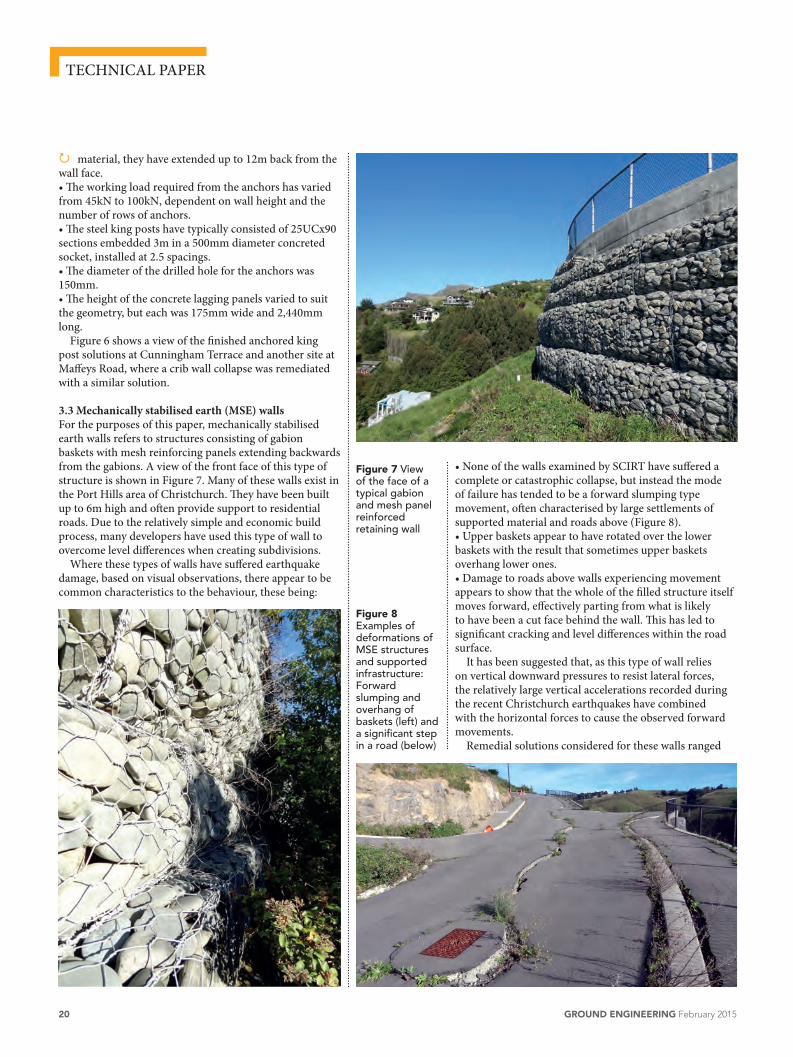
Where these types of walls have suffered earthquake damage, based on visual observations, there appear to be common characteristics to the behaviour, these being:
P
• None of the walls examined by SCIRT have suffered a complete or catastrophic collapse, but instead the mode of failure has tended to be a forward slumping type movement, often characterised by large settlements of supported material and roads above (Figure 8).• Upper baskets appear to have rotated over the lower baskets with the result that sometimes upper baskets overhang lower ones.• Damage to roads above walls experiencing movement appears to show that the whole of the filled structure itself moves forward, effectively parting from what is likely to have been a cut face behind the wall. This has led to significant cracking and level differences within the road surface.
It has been suggested that, as this type of wall relies on vertical downward pressures to resist lateral forces, the relatively large vertical accelerations recorded during the recent Christchurch earthquakes have combined with the horizontal forces to cause the observed forward movements.
Remedial solutions considered for these walls ranged
Figure 7 View of the face of a typical gabion and mesh panel reinforced retaining wall
Figure 8 Examples of deformations of MSE structures and supported infrastructure: Forward slumping and overhang of baskets (left) and a significant step in a road (below)

February 2015 GROUND ENGINEERING 21
Figure 9 A sacrificial drill bit for a “self-drilling” anchor (below left) and installation (below).
from complete rebuild, to provision of additional lateral support, acceptance of the future movement and budgeting for repairs for the lower height structures. In the end, for the larger structures, as their stability under static conditions appears acceptable (and the costs of remediating earthquake damage is significant), the preferred proposal was to install anchors through the face of the gabion baskets in an attempt to reduce any future forward slumping.
Self-drilling anchors of the type shown in Figure 9 were the preferred method. These were subject to an installation test prior to being specified for full scale repairs. At the time of writing, detailed design for these solutions were still being prepared and therefore installation photographs for actual repair projects were not yet available.
4. Further research suggestionIt will be noted that anchors have played a significant part in SCIRT’s retaining wall repair process. When the design process started over three years ago, there appeared to be little information concerning the capacity of anchors within the Port Hills loess and basalt. If anchors continue to be a favoured seismic repair method, further research into the bond capacities and extensions expected within these materials may help bring economy to future designs.
5. Concluding remarksThis paper has provided only the briefest overview of the total amount of retaining wall repair work being carried out by SCIRT in Christchurch. Nevertheless, it is hoped it has provided an appreciation of the careful efforts being made to increase the seismic resilience of Christchurch’s infrastructure. This is being done in accordance with SCIRT’s stated aim, which is “to create resilient
infrastructure that gives people security and confidence in the future of Christchurch”. The author is proud to have been able to have played a small part in trying to achieve this goal.
6. AcknowledgementsThe author would like to thank the management and owner participants of the Stronger Christchurch Infrastructure Rebuild Team for providing permission to publish the details contained in this paper.
The author acknowledges the advice provided by Tony Valentine, SCIRT geologist and site investigations coordinator, during the writing of the geological details contained in this paper.
The author would also like to thank Monica Lai for her patience and support during the preparation of this paper.
ReferencesBrown, L J; Weeber, J H (1992). Geology Map of the Christchurch Urban Area, 1:25,000 Scale Map.
Forsyth, P J; Barrell, D J A; Jongens, R (2008) (compilers). Geology of the Christchurch Area, Institute of Geological and Nuclear Sciences 1:250 000 geological map 16. 1 sheet. Lower Hutt, New Zealand. GNS Science. ISBN 987-0-478-19649-8
Ministry of Business Innovation and Employment (July 2014). Build It Right Canterbury Guide Document – Guidance on the Seismic Design of Retaining Structures for Residential Sites in Greater Christchurch.