Retail Fit Out Guide - The Galleria Fit Out... · Retail Fit Out Guide. CONTENTS HCJ/LJ/B100843/JR...
39
CONTENTS HCJ/LJ/B100843/JR Issue D - December 15 Contents Retail Fit Out Guide
-
Upload
hoangnguyet -
Category
Documents
-
view
241 -
download
4
Transcript of Retail Fit Out Guide - The Galleria Fit Out... · Retail Fit Out Guide. CONTENTS HCJ/LJ/B100843/JR...
CONTENTS
HCJ/LJ/B100843/JRIssue D - December 15
Contents
RetailFit Out Guide
CONTENTS
HCJ/LJ/B100843/JRIssue D - December 15
Contents
1.0 INTRODUCTION ............................................................................................................... 2
2.0 PROJECT DIRECTORY.................................................................................................... 3
3.0 LANDLORD APPROVAL PROCESS............................................................................... 5STEP 1 RETAILER BRIEFING ........................................................................................ 6STEP 2(A) CONCEPT DESIGN REVIEW ....................................................................... 7STEP 2(B) DETAILED DESIGN REVIEW ....................................................................... 8STEP 3 PRE START, HANDOVER AND FIT OUT.......................................................... 9STEP 4 COMPLETION AND CONSENT TO TRADE.................................................... 10
4.0 STORE DESIGN.............................................................................................................. 114.1 Introduction ...................................................................................................................... 114.2 Sustainability.................................................................................................................... 11
5.0 RETAIL SHELL SPECIFICATION .................................................................................. 125.1 Drawing Information from Landlord ................................................................................. 125.2 Queries/Further Information Required............................................................................. 125.3 Shopping Centre Structure & Fabric................................................................................ 125.4 Structural Specification .................................................................................................... 125.5 Service Doors .................................................................................................................. 135.6 Security Interface............................................................................................................. 135.7 Fire Alarm Connections ................................................................................................... 135.8 Sprinkler Connections...................................................................................................... 135.9 Smoke Extraction............................................................................................................. 135.10 External Plant Zones, Riser Access, Lightning Conductor Systems............................... 135.11 Ventilation Provision ........................................................................................................ 135.12 Cold Water Supplies ........................................................................................................ 135.13 Gas Supplies.................................................................................................................... 135.14 Electrical Supplies ........................................................................................................... 145.15 Foul Drainage Connections ............................................................................................. 145.16 Communications .............................................................................................................. 145.17 Landlord Services within the Unit .................................................................................... 14
6.0 TECHNICAL DESIGN ..................................................................................................... 156.1 Minimum Retailer Shop Fitting Requirements ................................................................. 156.2 Existing Shop Fitting ........................................................................................................ 156.3 Environmental Policy ....................................................................................................... 156.4 Surface Spread of Flame................................................................................................. 156.5 Windows .......................................................................................................................... 156.6 New Shopfront and Interior.............................................................................................. 166.7 Refuse Storage................................................................................................................ 176.8 Foul Drainage .................................................................................................................. 186.9 Water ............................................................................................................................... 186.10 Electricity.......................................................................................................................... 186.11 Gas .................................................................................................................................. 196.12 Retailer Plant Areas......................................................................................................... 196.13 Audio Systems, Public Address and Voice Alarm ........................................................... 196.14 Sprinklers ......................................................................................................................... 206.15 Fire Alarms....................................................................................................................... 216.16 Food Operator Kitchen Requirements............................................................................. 22
CONTENTS
HCJ/LJ/B100843/JRIssue D - December 15
Contents
7.0 FIT OUT ON SITE ........................................................................................................... 267.1 Generally.......................................................................................................................... 267.2 Contractor’s Site Team Contact Details .......................................................................... 267.3 Condition Survey ............................................................................................................. 267.4 Site Rules......................................................................................................................... 267.5 Existing Services ............................................................................................................. 277.6 Insurances ....................................................................................................................... 277.7 Retailer Responsibilities .................................................................................................. 287.8 Hoarding .......................................................................................................................... 287.9 Site Access ...................................................................................................................... 287.10 Deliveries / Waste Management...................................................................................... 297.11 Working Hours ................................................................................................................. 297.12 Permits to Work ............................................................................................................... 297.13 Parking............................................................................................................................. 307.14 Welfare............................................................................................................................. 307.15 Health & Safety................................................................................................................ 307.16 Fire Safety........................................................................................................................ 307.17 Prohibited materials or substances.................................................................................. 33
8.0 COMMISSIONING........................................................................................................... 348.1 Charges ........................................................................................................................... 348.2 Fire Alarm Connection Procedure ................................................................................... 348.3 Sprinkler Connection Procedure...................................................................................... 348.4 Cold Water Connection Procedure .................................................................................. 358.5 Foul Drainage Connection Procedure ............................................................................. 35
9.0 CONSENT TO TRADE.................................................................................................... 36
The following are Appendices to the Fit Out Guide and are separate documents on the website:
APPENDIX A – BLOCK PLANSAPPENDIX B – RETAIL DESIGN CRITERIAAPPENDIX C – APPROVAL PROCESS SUBMISSION FORMSAPPENDIX D – LOW CARBON FIT OUT GUIDEAPPENDIX E – PRE START AGENDAAPPENDIX F – COMMISSIONING CHECKLISTAPPENDIX G – E PERMIT SYSTEM

1.0 – INTRODUCTION
HCJ/LJ/B100843/JRIssue D - December 15 2
1.0 INTRODUCTIONThe galleria is an outlet shopping and leisure centre of some 40,000m2 on two levels comprising30,000 m2 of designer outlets, 15 restaurants and coffee shops and a 9-screen cinema.
This guide is designed to lead you through the Retail Delivery process throughout all stages includingparties involved, the process to be followed, concept design, technical design, fit out, commissioningand finally consent to trade.
The galleria will provide support to the Retailer to ensure a high standard of design and smoothtransition through the process however it is the Retailer’s responsibility to ensure their agents,designers and contractors are aware of the contents of this document and comply with allrequirements.
Whilst all information contained within this document is given in good faith and believed to be accurateat the time of circulation, it is not intended to constitute any legal representation or warranty andRetailers are recommended to undertake their own independent investigations, inspections, surveysand enquiries to satisfy themselves on all points. Information has been collated from various sourcesincluding the design consultants for the Centre in order to produce a simplified source of relevantinformation.
This Fit Out Guide is intended to cover all primary information however there will inevitably besituations which differ and/or require different treatment. The retail delivery process is a framework toallow communication of these issues to ensure resolution to all parties’ satisfaction.
Land Securities are committed to delivering sustainable developments and recognise the importanceof working in partnership with our occupiers to make a difference towards this goal. We haveproduced a Low Carbon Fit Out Guide (refer to Appendix D) to provide guidance on the practical waysretailers can reduce energy by good practice design and effective energy management. All retailersand catering unit operators are asked to consider the guidance given.
We also advocate the use of sustainable materials when carrying out shop-fits. If you require anyassistance please do not hesitate to contact a member of Centre Management or Land SecuritiesEnvironment Team.

2.0 - PROJECT DIRECTORY
HCJ/LJ/B100843/JRIssue D - December 15 3
2.0 PROJECT DIRECTORYThe Retailer will be expected to issue a Project Directory at the earliest opportunity and nominate asingle point of contact for the Retail Delivery Manager.
Communications by email are to include in the header the shop unit reference, Retailer trading nameand primary content of the email.
Key contacts for the Landlord’s team are noted below:-
LANDLORD’S TEAM
Portfolio/Leasing Contact: Amy McGregorManager Address: Land Securities, 5 Strand, London, WC2N 5AF
E-mail: [email protected]: 0207 413 9000
Retail Portfolio Contact: Jack BusbyDirector Address: Land Securities, 5 Strand, London, WC2N 5AF
E-mail: [email protected]: 0207 413 9000
Retail Delivery Contact: Roger DuncombeManager Address: The galleria, Comet Way, Hatfield, Herts, AL10 0XR
E-mail: [email protected]: 01707 256 860
Retail Designer Contact: Linda TaitAddress: Tait Design, Harpenden Hall, Southdown Road,
Harpenden, Herts, AL5 1TEE-mail: [email protected]: 01582 460 990
General Manager Contact: Tim StirlingAddress: The galleria, Comet Way, Hatfield, Herts, AL10 0XRE-mail: [email protected]: 01707 256 860
Centre Technical Contact: Tim CootesServices Manager Address: The galleria, Comet Way, Hatfield, Herts, AL10 0XR
E-mail: [email protected]: 01707 256 860
Centre Operations Contact: Jon CarterManager Address: The galleria, Comet Way, Hatfield, Herts, AL10 0XR
E-mail: [email protected]: 01707 256 860
Marketing Manager Contact: Ellie PennyAddress: The galleria, Comet Way, Hatfield, Herts, AL10 0XRE-mail: [email protected]: 01707 256 860
Centre Security Telephone: Security Control Room - 01707 256860 ext 231
2.0 - PROJECT DIRECTORY
HCJ/LJ/B100843/JRIssue D - December 15 4
Building Control Contact: Richard MurrellAddress: Welwyn Hatfield District Council
Planning Department/Building ControlCouncil OfficesWelwyn Garden CityHerts AL8 6AE
E-mail:Telephone: 0707-331212
Fire Officer Contact:Address: Hertfordshire County Fire Brigade
153 London Rd,St. AlbansHerts AL1 1TQ
E-mail:Telephone: 0300 1234046
Planning Contact Contact: Mark PeacockAddress: Welwyn Hatfield District Council
Planning Department/Building ControlCouncil OfficesWelwyn Garden CityHertsAL8 6AE
E-mail:Telephone: 0707-331212
PREFERRED SUPPLIERS
Fire AlarmInstallations
Contact: Neil Thompson
Address: Trinity Protection Systems Ltd, 121a Milton Park, Abingdon,Oxon, OX14 4SA
E-mail: [email protected]: 01235 862 456
Sprinkler Installations Contact: Ashley GortonAddress: Blue Shield Fire Protection Ltd, Blue Shield House, Queens
Street, Tring, Herts, HP23 68QE-mail: [email protected]: 01442 828 000
3.0 - LANDLORD APPROVAL PROCESS
HCJ/LJ/B100843/JRIssue D - December 15 5
3.0 LANDLORD APPROVAL PROCESSThere are four key stages to the Retail Delivery process and Retailer’s should ensure they liaise withthe Landlord’s Retail Delivery Manager at the earliest possible stage regardless of the scope of theproposal (i.e. minor alterations or full unit re-fit) to ensure the appropriate level of input is agreed.
Following agreement on the Scope of Works between the Landlord’s Portfolio Manager and theRetailer the following process will need to be followed:-
3Pre-Start
Handover & FitOut
4Completion &
Consent to Trade
2Design Review
12
Retailer Briefing
Retailer briefing by the Retail Delivery Manager to introduce theprocess and issue the guides.
Shop fit deposits confirmed.
Retailer submits ‘Concept Design Submission Form’.Concept stage signed off with the ‘Concept Design Approval’.
Retailer submits ‘Detailed Design Submission Form’.Detailed design stage signed off with the ‘Detailed DesignApproval’.
Deposit sums transferred (where applicable).
Retailer meets with the Centre Management Team and submitspre-start information using the ‘Pre Start InformationSubmission Form’.Stage signed off with the ‘Pre Start Approval’ to allow work tocommence on site.
The pre-start process and work on site is monitored by theCentre Management Team.
Retailer submits as-built information and commissioningcertificates using the ‘Consent to Trade Form’.The unit may open for trade following issue of the ‘Consent toTrade’.
The damages deposit is released following completion of anysnagging issues.
The documentation deposit is released following receipt of theas-built drawings, O&M Manuals and Health & Safety File.
3.0 - LANDLORD APPROVAL PROCESS
HCJ/LJ/B100843/JRIssue D - December 15 6
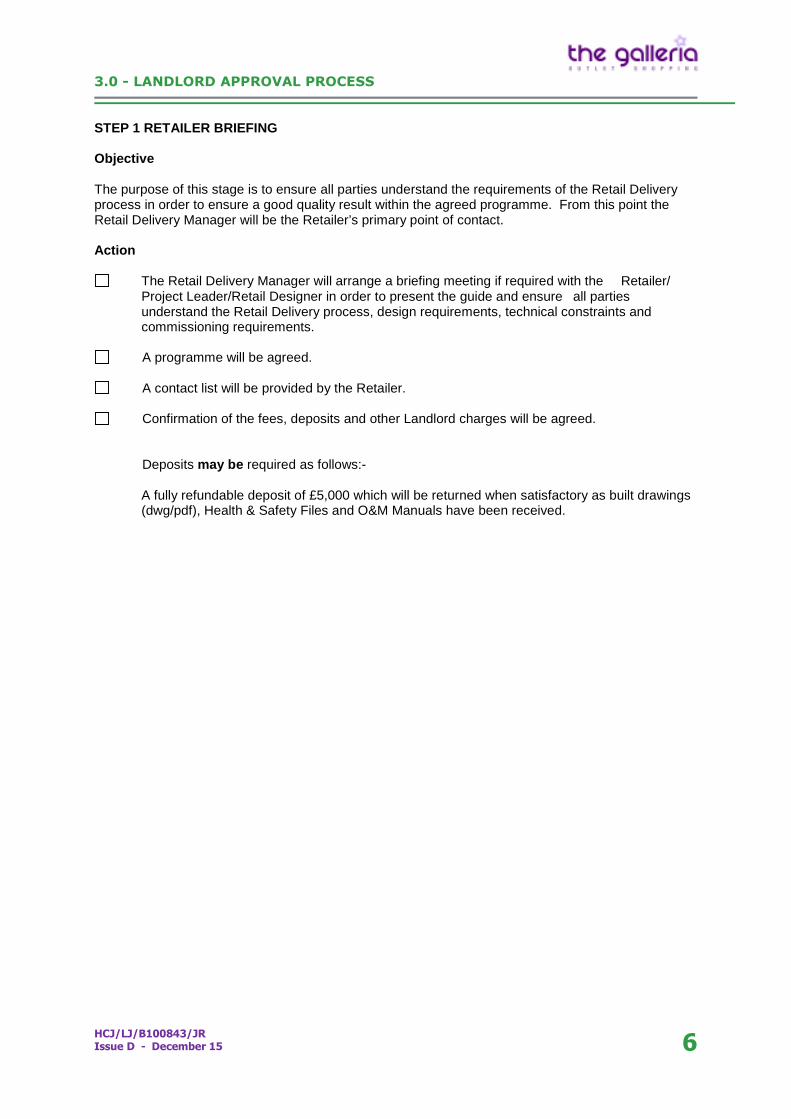
STEP 1 RETAILER BRIEFINGSTEP 1 RETAILER BRIEFING
Objective
The purpose of this stage is to ensure all parties understand the requirements of the Retail Deliveryprocess in order to ensure a good quality result within the agreed programme. From this point theRetail Delivery Manager will be the Retailer’s primary point of contact.
Action
The Retail Delivery Manager will arrange a briefing meeting if required with the Retailer/Project Leader/Retail Designer in order to present the guide and ensure all partiesunderstand the Retail Delivery process, design requirements, technical constraints andcommissioning requirements.
A programme will be agreed.
A contact list will be provided by the Retailer.
Confirmation of the fees, deposits and other Landlord charges will be agreed.
Deposits may be required as follows:-
A fully refundable deposit of £5,000 which will be returned when satisfactory as built drawings(dwg/pdf), Health & Safety Files and O&M Manuals have been received.
3.0 - LANDLORD APPROVAL PROCESS
HCJ/LJ/B100843/JRIssue D - December 15 7
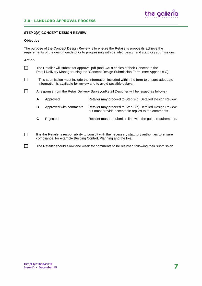
STEP 2(A) CONCEPT DESIGN REVIEWSTEP 2(A) CONCEPT DESIGN REVIEW
Objective
The purpose of the Concept Design Review is to ensure the Retailer’s proposals achieve therequirements of the design guide prior to progressing with detailed design and statutory submissions.
Action
The Retailer will submit for approval pdf (and CAD) copies of their Concept to theRetail Delivery Manager using the ‘Concept Design Submission Form’ (see Appendix C).
This submission must include the information included within the form to ensure adequateinformation is available for review and to avoid possible delays.
A response from the Retail Delivery Surveyor/Retail Designer will be issued as follows:-
A Approved Retailer may proceed to Step 2(b) Detailed Design Review.
B Approved with comments Retailer may proceed to Step 2(b) Detailed Design Reviewbut must provide acceptable replies to the comments.
C Rejected Retailer must re-submit in line with the guide requirements.
It is the Retailer’s responsibility to consult with the necessary statutory authorities to ensurecompliance, for example Building Control, Planning and the like.
The Retailer should allow one week for comments to be returned following their submission.
3.0 - LANDLORD APPROVAL PROCESS
HCJ/LJ/B100843/JRIssue D - December 15 8
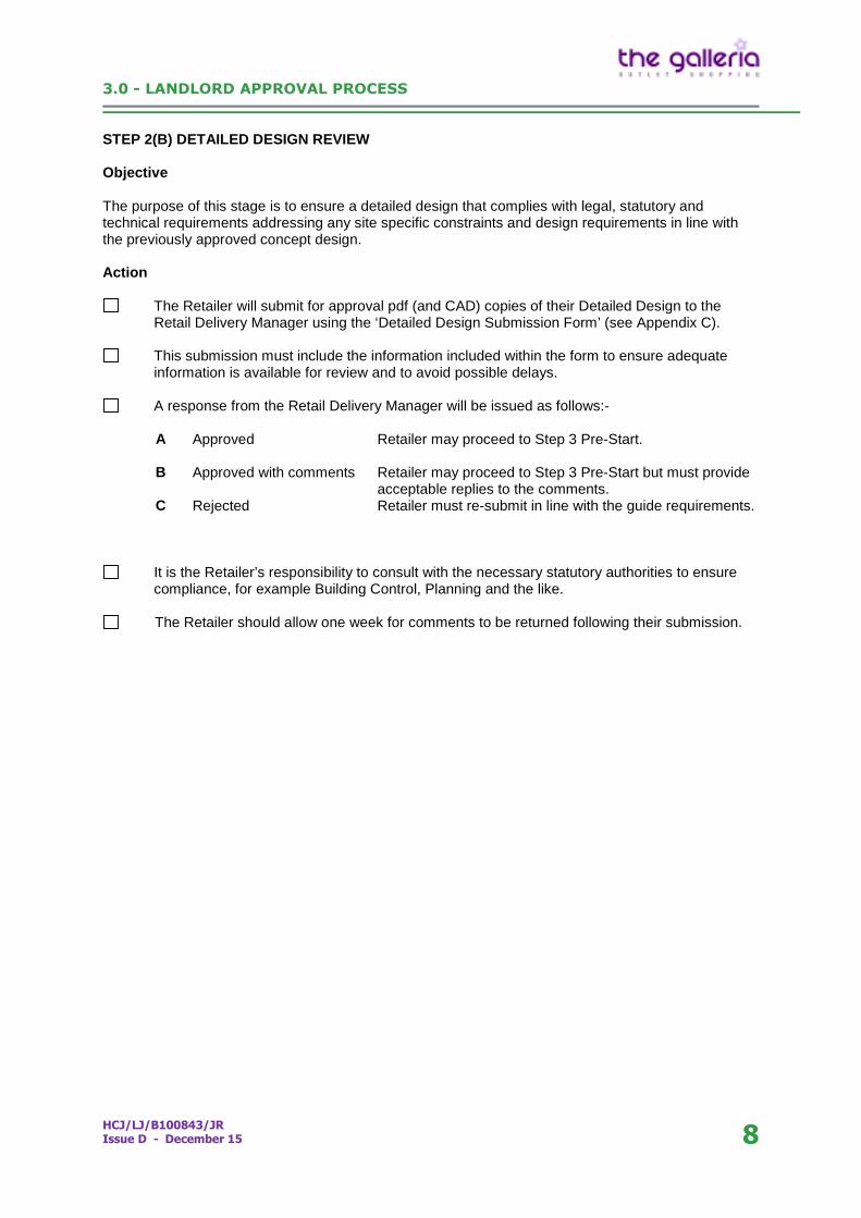
STEP 2(B) DETAILED DESIGN REVIEWSTEP 2(B) DETAILED DESIGN REVIEW
Objective
The purpose of this stage is to ensure a detailed design that complies with legal, statutory andtechnical requirements addressing any site specific constraints and design requirements in line withthe previously approved concept design.
Action
The Retailer will submit for approval pdf (and CAD) copies of their Detailed Design to theRetail Delivery Manager using the ‘Detailed Design Submission Form’ (see Appendix C).
This submission must include the information included within the form to ensure adequateinformation is available for review and to avoid possible delays.
A response from the Retail Delivery Manager will be issued as follows:-
A Approved Retailer may proceed to Step 3 Pre-Start.
B Approved with comments Retailer may proceed to Step 3 Pre-Start but must provideacceptable replies to the comments.
C Rejected Retailer must re-submit in line with the guide requirements.
It is the Retailer’s responsibility to consult with the necessary statutory authorities to ensurecompliance, for example Building Control, Planning and the like.
The Retailer should allow one week for comments to be returned following their submission.
3.0 - LANDLORD APPROVAL PROCESS
HCJ/LJ/B100843/JRIssue D - December 15 9
STEP 3 PRE START, HANDOVER AND FIT OUTSTEP 3 PRE-START, HANDOVER AND FIT OUT
Objective
The purpose of this stage is to ensure the Retailer has satisfied the requirements for all approvals, thenecessary pre-start information has been received and the Retailer’s contractor team has been briefedby the Centre Management in relation to site constraints, site rules and the like.
Action
The Retailer will be responsible for arranging a meeting with the Centre Management Teamand attending this together with their Project Leader and Principle Contractor having firstsubmitted the required pre-start information as noted within the ‘Pre Start InformationSubmission’ Form (see Appendix C).
A response from the Retail Delivery Manager will be issued as follows:-
A Approved Retailer may proceed to Fit Out.
C Rejected Retailer must re-submit in line with the guide requirements.
Works will not be permitted to commence on site without:-
A completed Agreement for Lease (if applicable). Payment of the deposits and fees (as appropriate). Approval of the detailed design. Acceptance of the pre-start information. Building Regulations plans approval. Approval of sprinkler alterations by the building insurers (as appropriate). All Health & safety information being available.
3.0 - LANDLORD APPROVAL PROCESS
HCJ/LJ/B100843/JRIssue D - December 15 10
STEP 4 COMPLETION AND CONSENT TO TRADESTEP 4 COMPLETION AND CONSENT TO TRADE
Objective
The purpose of this stage is to ensure the work on site has been completed in accordance with theagreed plans, services have been commissioned and interfaced with the Landlord’s systems whereappropriate and a Building Regulation Completion Certificate has been issued.
Action
Five days prior to the proposed works completion date, the Retailer is to notify theRetail Delivery Manager to allow an inspection.
The Retail Delivery Manager will issue a list of any snagging for completion.
The Retailer will submit the ‘Consent to Trade Submission Form’ together with allappropriate documentation (see Appendix C).
The Retail Delivery Manager will issue a ‘Consent to Trade’ notice allowing the Retailer totrade. THE UNIT WILL NOT BE PERMITTED TO TRADE WITHOUT THIS.
Deposits will be released subject to receipt of the relevant as built information andcompletion of any snagging/damages (snagging/damages are to be rectified within 14 days ofthe issue of the notice from the Retail Delivery Manager).
4.0 - STORE DESIGN
HCJ/LJ/B100843/JRIssue D - December 15 11
4.0 STORE DESIGN4.1 Introduction
Tait Design has produced a document to assist Retailers in achieving a high level of storedesign commensurate with our outlet shopping ethos. This provides guidance on the differentareas of the scheme and treatment of certain elements to ensure an appropriate designstandard.
The ‘Retail Design Criteria’ guide is included within Appendix B.
Where appropriate, The galleria may involve a Retail Designer to assist the Retailers with theconcept proposals where this is considered necessary to ensure a high design standard insensitive areas of the Centre.
4.2 Sustainability
As noted in the introduction to the guide, The galleria has a strong commitment tosustainability (refer to Sustainability Guide within Appendix D) and every opportunity should betaken to utilise sustainable products, materials, energy and design to achieve bothenvironmental improvement and reduced operational costs.
The following are a number of ways where improvements can be achieved:-
use of heat recovery systems efficient controls to heating and cooling equipment natural lighting and ventilation where possible together with efficient controls improvements to Part L ‘U’ value requirements use of natural quality materials with less intensive manufacturing processes where
possible (i.e. natural stone, limestone, ceramic, granite, terrazzo, hardwood timberfrom FSC approved sources, glass, metals)
use of local suppliers to minimise transportation impacts use of ISO14001 accredited supply chains
There are numerous sources of advice however www.carbontrust.co.uk provides a usefulstarting point with links to additional resources.
5.0 – RETAIL SHELL SPECIFICATION
HCJ/LJ/B100843/JRIssue D - December 15 12
5.0 RETAIL SHELL SPECIFICATION5.1 Drawing Information from Landlord
There are no Landlord’s drawings included in this document. Retailers must undertake theirown investigations, inspections, surveys and enquiries.
5.2 Queries/Further Information Required
Please submit any queries or requests for further information that may be required to thespecific specialist, copied to the Retail Delivery Manager.
5.3 Shopping Centre Structure & Fabric
The Shopping Centre has piled foundations with reinforced concrete ground bearing slabs tothe east and west areas. The structure above the A1M tunnel is both directly supported by thetunnel roof structure and in places pre-cast concrete planks and/or in situ concrete on blockwork walls. The Pod has a suspended concrete slab supported on band bridge beamsspanning between pile caps.
Floor structures are generally in situ concrete on metal decking supported by a beam structureon a 7.2m x 7.2m grid. The first floor of the mall spans from secondary beams on to plategirders spanning 24m between twin columns at the edge of the mall and stanchions positionedover the central wall of the A1M.
The roof is designed as a series of tension assisted curved CHS lattice trusses spanning48.6m at 7.2m centres, supporting long spanning Plannja TRP200 metal decking andPilkington’s Planar glass roof lights.
The Odeon Pod has pre stressed concrete bridge beams spanning 24m on to reinforcedconcrete beams and columns with a steel frame to the two storey structure to the East of thetunnel on a 7.2m x 6m grid broken down into 12m max spans for the floors and 18m spans forthe roof.
The Bridge Link first floor has steel beams at 3.6m centres supporting a structural concreteslab with secondary beams supported by a series of 18 parallel frames generally set at 7.2mcentres (14.4m max).
Roofs to the east retail, Bridge Link and Odeon Pod comprise Sarnafil S327-12 EL polymericwaterproofing with hot welded joints. To the west retail the car park structure over-sails theretail comprising a mastic asphalt paving finish.
External walls to the galleria and Odeon Pod comprise a 4mm rainscreen aluminium claddingsystem fixed back to a steel frame, 100 solid block, 75mm cavity and inner skin of 125mminsulated block. Louvres are incorporated into the cladding system all of which is finished witha PVf2 coating.
5.4 Structural Specification
The ground floor has a ground bearing concrete slab designed to a maximum superimposedloading of 10kn/m2. There is a 75mm allowance for applied Retailer screeds/finishes.Downstand beams occur on partition lines.
The first floor has an insitu concrete deck supported on permanent metal decking designed toa maximum superimposed loading of 7.5kn/m2.
There is a 75mm allowance for applied Retailer screeds/finishes (maximum 1.8kn/m2).Downstand beams occur on partition lines.
5.0 – RETAIL SHELL SPECIFICATION
HCJ/LJ/B100843/JRIssue D - December 15 13
An allowance of 0.5kn/m2 has been made within the roof structure for Retailer’s suspendedservices and finishes.
Internal walls generally comprise solid fair faced dense concrete blocks (at first floor walls arelightweight steel framed plasterboard stud where located off the structural grid).
5.5 Service Doors
Service doors are aluminium faced timber solid core doors in aluminium frames where locatedwithin the cladding system and exterior grade solid core timber doors with a painted plywoodfinish in steel door frames where located within blockwork.
5.6 Security Interface
There is no security interface between the Landlord and Retailer security systems.
5.7 Fire Alarm Connections
A fire alarm interface unit is located within each unit ready for connection by the Retailer’slocal alarm panel using the Centre’s preferred contractor.
Mall kiosks are served directly from the Landlord’s infrastructure.
5.8 Sprinkler Connections
A sprinkler supply is terminated within each unit complete with zone check flow switch.
5.9 Smoke Extraction
The galleria generally has an integrated smoke extract system located at high level withineach unit. All ceilings must achieve a minimum 30% free area and allow for make-up air fromthe mall to ensure the correct operation of the extract system.
5.10 External Plant Zones, Riser Access, Lightning Conductor Systems
Plant locations and service routes are to be agreed on site with the Centre ManagementTeam.
A lightning protection installation is in place and Retailer’s will be required to connect any roofplant to this system and provide relevant certification on completion.
5.11 Ventilation Provision
Fresh air is available through either wall mounted supply and extract louvers suitable forconnection to the Retailer’s A/C system or via a fresh air duct connection from the Landlord’smechanical ventilation system.
Where louvres are not available at the rear of the unit, provision has been made for thelocation of Retailer’s heat exchange equipment elsewhere.
5.12 Cold Water Supplies
A water supply of not less than 15mm is generally provided in most units at a stop tap positionwithin the unit.
5.13 Gas Supplies
There is no gas supply available to retail units. Gas supplies to the Bridge Link andOdeon Pod areas are the responsibility of the Retailer.
5.0 – RETAIL SHELL SPECIFICATION
HCJ/LJ/B100843/JRIssue D - December 15 14
5.14 Electrical Supplies
Each unit has a 3 phase electrical supply via a busbar distribution system originally sized toprovide 150 watts/sqm. Supplies are sub-metered from the Landlord’s incoming supply andcosts recovered from individual Retailer’s based on use.
5.15 Foul Drainage Connections
100mm and 50mm SVP connections are generally available to most units suitable for Retailerconnections.
5.16 Communications
There is provision to connect to the BT network subject to the Retailer making the appropriateapplication through the selected telecoms supplier (a maximum of two lines per unit ispermitted).
A communal TV/FM aerial system is available within the scheme subject to application to theCentre Management.
5.17 Landlord Services within the Unit
In most units, the Retailer will be required to provide access to services – rodding to soil andrain water pipes, fire damper reset hatches and smoke mechanical ventilation dampers andmotors. The Retailer’s fit out design must allow safe access to these positions.
Retailers are advised that in some instances Landlord’s services are routed through units.The Retailer must inspect on site to ascertain the location, disposition and size of the servicesand ensure adequate access is maintained, avoiding any interference and not affixing anyitems to the services.
6.0 - TECHNICAL DESIGN
HCJ/LJ/B100843/JRIssue D - December 15 15
6.1 Minimum Retailer Shop Fitting Requirements
The Retailer shall not interfere with the fabric or structure of the building in any way,whatsoever, without the prior written approval of the Landlord. Work to the fabric includes, butis not confined to the laying of screeds, alterations, connection to services, the cutting ofchases, small diameter holes and the like.
The Retailer shall not interfere in any way with the integrity of the fire barriers (dividingwalls/floor between the Unit and adjacent units or adjacent Landlord areas), structural fireprotection services or protected escape routes. In seeking approval for such servicespenetrations, or for other works which may affect the integrity of fire barriers around the unit(e.g. external walls, dividing walls, floors, wall between unit and services corridor), the Retailershall submit proposed details of fire stopping/fire resisting construction with supporting fire testdocumentation as part of the Building Regulation Submission.
Retailers are expected to comply with all current statutory requirements, British Standards,Codes of Practice, Euro Standards and general best practice guidance in the delivery of theirfit out.
6.2 Existing Shop Fitting
Retailers who retain existing shop fitting elements including services when they take over aunit will be responsible for their full compliance with the Landlord’s requirements and anystatutory regulations.
6.3 Environmental Policy
Retailers should comply with the Landlord’s Environmental Policy and are actively encouragedto improve their environmental ambitions.
The Retailer should demonstrate consideration of the usage of sustainable products as part oftheir fit-out proposals.
The usage of recycled products from sustainable sources and an environmentally friendlywaste disposal strategy will be encouraged.
6.4 Surface Spread of Flame
All materials facing the Mall circulation routes must comply with the European classification forfire spread Class B-s3, d2 (old National Class 0), except shopfront framing as provide for inBS9999.
All surfaces within the units must comply with Euro Class C-s3, d2 (old National Class 1).
The Retailer shall ensure the fit out does not obstruct Landlord services, access panels, vents,outlets, etc.
6.5 Windows
All shopfront or display windows will be the responsibility of the Retailer. Windows in externalwalls, other than shopfront or display windows must be as per the Landlord’s shellspecification and will be to match existing.
6.0 - TECHNICAL DESIGN
HCJ/LJ/B100843/JRIssue D - December 15 16
6.6 New Shopfront and Interior
The following requirements are all subject to the Landlord’s approval and must comply withall Building Regulations and other statutory authority requirements.
GlassAll shopfront glazing must be ‘safety glass’ to BS6262. Laminated glass is preferred totoughened glass as it retains its form when fractured. However toughened glass may berequired for smoke control where applicable. All toughened glass should be heat soaked toBS EN 14179.
Shopfront StabilityShopfront glazing must be designed within the maximum deflection criteria of BS 6180, underhorizontal imposed loads as set out in BS 6399-1. The maximum permitted deflection is25mm. This will determine the thickness of glass used and in the majority of cases, framelessjoints in glazing may require support fins or equivalent support.
ManifestationManifestation is required to shopfront glazing in accordance with Building Regulations Part M.
Access and Facilities for the DisabledBuilding/shop fitting work must comply with Approved Documents M Access Facilities for theDisabled and the Disability Discrimination Act. A level access will be required into all shopsand a staircase suitable for ambulant disabled persons, lifts and WC facilities depending onthe size, location and configuration of the particular shop unit.
Wheelchair Accessible Cashier PointsCashier counters should include suitable sections designed for use by wheelchair usingcustomers.
Audio ReinforcementApproved audio loops should be incorporated into cashier counters with the appropriatesignage. Staff should have the facility to turn down the volume of PA systems while servingcustomers with hearing difficulties.
Walls/PartitionsThese must adhere to the required fire rating and Class 1 surface spread of flamerequirements. Stability posts and head restraint angles must be protected to half hour fireresistance. No fixing to unit block walls permitted (apart from lateral restraints). Stud wallstructures to be fixed down to slab.
DoorsMaintain fire rating and means of escape purposes. Incorporate relevant statutory, means ofescape, safety signage and emergency exit ironmongery. Include for a lobby at the rear of theunit where required.
Fire Exit DoorsFire exit doors from retail areas should not be mirror faced and should be readily identifiable,incorporating a vision panel to Building Regulations Part M requirements.
LobbyWhere required by Building Control, the Retailer is to provide a fire rated lobby within thedemise, as protection to the rear service corridors. Ensure all penetrations for services arefire stopped and the fire escape route is kept clear at all times.
6.0 - TECHNICAL DESIGN
HCJ/LJ/B100843/JRIssue D - December 15 17
CeilingsImaginative ceiling design is encouraged and should be integrated with the existing smokecontrol requirements as set out in the Fire Strategy and with the mall ceiling height. The ceilingfacing the mall must have properly integrated access hatches to enable access to Landlord’sequipment above.
LightingExciting and inspirational lighting design is encouraged. Comply with CIBSE Guide, Codes ofPractice and Document L of the Building Regulations.
No naked fluorescent or cold cathode tubes will be allowed in the mall without prior approvalfrom the Landlord.
Lighting for halo illumination and coving should be continuous, even and concealed.
Lighting in units should be a minimum of 1000 lux in the shop display windows and entrance.Sufficient lighting to be incorporated for safety purposes for out of hours use.
Emergency lighting will comply with BS 5266, Part 1, Category M/2 to provide maintainedemergency lighting for 2 hour duration.
Colour ContrastRetailers should incorporate suitable colour contrast into their designs to assist partiallysighted customers and staff navigate around the unit.
Sound InsulationRetailer’s must ensure and demonstrate that sound insulation between units is adequate tothe purpose of the particular use to be carried out.
FinishesThese must be to the high standard commensurate with the Centre as a whole.
Deleterious MaterialsNo deleterious materials are to be used based on the Land Securities assessment of currentdeleterious materials.
Demise SignageA Landlord’s specified signboard must be positioned on the rear door to the service corridorfor rear service access (and any risers/plant).
Medium Density Fibre BoardMedium Density Fibre board (MDF) is used in most construction. When cutting or machiningor using any other process that will cause dust to occur suitable extraction must be used. Nobare edges will be allowed and all surfaces must be sealed. All MDF delivered to site must besealed.
Aerial and Satellite SystemsAny such systems must be located in a position previously approved by the Landlord. Theirheight will not exceed the height of plant screening.
6.7 Refuse Storage
The Retailer is required to store refuse bins in their unit until they are taken to the centralcompactor. Space within the leased unit must therefore be made for these bins.
6.0 - TECHNICAL DESIGN
HCJ/LJ/B100843/JRIssue D - December 15 18
All refuse rooms must be finished to withstand the impact of the bins and allow steam cleaningor wash down. Any newly constructed bin stores must have a gully in the floor, and extractionsystem that vents to atmosphere, have a 2 hour envelope, being fitted with a sprinkler headand smoke head.
6.8 Foul Drainage
Retailers shall be responsible for the installation of foul drainage systems within their demise.
Retailers shall protect Landlord’s systems from blockage or damage. Any damage causedshall be made good at the expense of the Retailer in whose unit it originated.
All installations and sanitary accommodation shall meet all Building Regulations and Healthrequirements.
Where applicable, the Retailer will be responsible for grease treatment/interception to protectthe below ground drainage system, consisting of a BBA approved Aluline enzyme convertersupported by a maintenance regime procedure.
6.9 Water
Retailers shall be responsible for the installation of a water distribution system within theirdemise.
All water connections/pipework must be installed/completed in copper, not plastic and no pushfit connections will be permitted.
Water distribution installations by the Retailer must be in accordance with the water utilitycompany’s requirements, the Water Regulations and the relevant British Standards.
All Domestic Services pipework and fittings fitted within a unit shall be chlorinated by theRetailer in accordance with BS6700 and Health and Safety guidance note ACOPL8 andMSE(G) (Prevention or Control of Legionella).
6.10 Electricity
The Retailer’s installation includes mains distribution and switchgear fed from the mainincoming supply isolator, comprising of all circuit wiring, switching, lighting and any specialistequipment required. The main meter is the Landlord’s equipment and electricity consumed willbe recharged to the Retailer.
All Retailer’s electrical installations will comply with:-
NICEIC Regulations BS7671 Health and Safety at Work Act Current Building Regulations
All cabling shall be carried out in low smoke and fume rated cabling. Flying leads greater thanone metre will not be permitted.
All cabling must be contained in:-
Conduit (metal) or Trunking or Tray (metal) with cabling supported at a suitable pitch.
6.0 - TECHNICAL DESIGN
HCJ/LJ/B100843/JRIssue D - December 15 19
6.11 Gas
Any gas supply installed by the Retailer must be completely in accordance with National Gridrequirements, the Building Regulations and British Standards.
6.12 Retailer Plant Areas
Each Retailer is responsible for the supply and installation of all heating, ventilation andcooling systems to meet statutory requirements and maintain comfort conditions within theirdemise. The Retailer’s installed external plant must meet the following noise suppressionrequirement as adopted by the Landlord:
1. Air handling units 45db measured at 3metres from source.2. Heat rejection plant 45db measured at 3metres from source.3. Supply and exhaust fans 45db measured at 3metres from source.
No air is to be taken from or discharged into the mall (except for kiosks).
The Retailer must ensure its services are only installed in the designated areas.
The Retailer shall not modify or penetrate the roof finish. Retailer’s plant shall be bolted topaving slabs within the Retailer plant area on the roof. The use of pad-stones or raisedconcrete plinths must be agreed with the Landlord prior to work commencing.
Concrete bases must allow the roof to drain as designed and must be of a depth so thatmechanical fixings do not penetrate the roof membrane below.
Air supply and extract ducts, cables and pipework from the unit to external plant must berouted via the dedicated riser (where available) and fully weathered at roof level.
Retailers shall ensure that unused ducts are sealed with a permanent weather proof covercompatible with the Landlord’s roof finishes.
The colour and appearance of plant may be controlled in exposed locations and the Retailerwill be responsible for obtaining all relevant planning consents.
6.13 Audio Systems, Public Address and Voice Alarm
Audio systems within the unit must not exceed a sound pressure level of NR45 at theshopfront.
Where the Retailer provides and installs a separate standalone public address or voiceevacuation system as part of the fit out works, then the system shall be designed to allowcontrol from the Landlord’s main system.
The interconnection between the Landlord’s and Retailer system shall be via an interface unitlocated at the rear of each unit.
The Retailer’s public address installation shall interface with the Landlord’s system such thatin event of a fire condition the Retailer’s nonessential broadcasts are silenced via theRetailer’s fire alarm system.
Where the Retailer has provided a full voice evacuation system then the Landlord’s systemshall silence any broadcasts in favour of the Landlord’s pre-recorded emergency andevacuation messages via the Retailer’s amplification equipment.
6.0 - TECHNICAL DESIGN
HCJ/LJ/B100843/JRIssue D - December 15 20
6.14 Sprinklers
The Retailer shall install a sprinkler system within their demise from a connection provided bythe Landlord or may modify existing installations subject to the Landlord’s specific writtenapproval.
The galleria’s existing system is a category Ordinary Hazard Group III system. It is currentlyserved with standard heads. In the event of a restoration to shell being undertaken then theheads on the system should be replaced with fast response heads therefore concealed headsmust not be used. Also ZX1 sprinkler heads must not be used. Flexible rapid type dropconnectors must not be used and all second fix pipework shall be of rigid construction.
Any alterations to the existing system will require Landlord’s insurers’ approval. Three hardcopies of the revised system layout will be required by the Landlord for this purpose.
Flexible pipework will not be permitted. A drain down should be provided at the rear of the unitat low level to facilitate testing of the flow switch. Sprinkler design and installation work mustbe carried out by a bona fide sprinkler company approved by the Loss Prevention CertificationBoard (LPCB) to at least level 3 under their LPS Sprinkler Contractor’s Scheme and be ISO9001 Quality Assurance certified
Installations must comply with the LPC regulations and the BS 5306 part 2 Ordinary HazardGroup III.
The installation of a sprinkler system is to be completed and approved before combustiblematerials are delivered to the unit and the Retailer must provide all relevant test certificatesprior to connection onto the Landlord’s system.
Draining down or charging up of shop unit sprinkler installations is to be carried out under thesupervision of the Landlord/Centre Management and following 5 days’ notice in advance ofthis date. Under no circumstances is the Retailer to operate the isolating valve located in thecorridor.
The Retailer shall employ the Landlord’s sprinkler specialist to provide the necessaryattendance during the ‘charging up’ of the shop unit sprinkler installation.
Sprinkler supplies to shop units will incorporate a monitored stop valve. Each Retailer shallinstall a water flow switch with pumped zone check after the stop valve, connected into theretail unit interface box, so that the fire alarm system will know the location of an activatedsprinkler system. The Retailer shall be responsible for installing a test point drain facilitywithin their demise.
The Retailer is encouraged to integrate the range pipework within the fitting-out and tominimise the amount of exposed pipework visible in retail areas. This is particularly relevantto void areas behind the shopfront and under open plan staircases.
Dry sprinkler heads must be provided to all cold storage areas.
All cooker hoods must have an Ansel fire suppression system.
The method(s) of storage, storage heights, and types of goods stored affect the capability of asprinkler system to control or extinguish a fire. Therefore it is important to ensure that thestorage heights do not exceed the limitations imposed by the system design. The maximumstorage heights should be clearly indicated on the sprinkler installation drawings. If you are inany doubt or cannot easily access this information you should seek confirmation from theLandlords insurers.
6.0 - TECHNICAL DESIGN
HCJ/LJ/B100843/JRIssue D - December 15 21
In addition, please note that a clear space of 500mm is to be maintained below the sprinklerdeflector plates. Obstructions that interfere with the discharge pattern of sprinklers willadversely affect the system’s performance and its capability to control a developing fire. Thismay not be achieved if appropriate clearances are not maintained.
The clear space requirement therefore takes precedence over any storage height limitationswhich apply. If ceiling heights are restricted, it may be necessary to reduce heights to belowthe permitted maximums as specified by the system design, in order to achieve the requiredclear space.
Goods stored too close to sprinklers are a major cause of mechanical damage, theconsequences of which would be costly repairs; loss of essential fire protection whilst repairsare completed; severe business disruption; significant water damage to buildings andcontents.
6.15 Fire Alarms
Design standards:
The Centre operates a system design category of BS5839:1:2002+A2/2008 L1, which requiresthe installation of fire detection in all areas with the exception of areas deemed to be of lowrisk such as:
Toilets, shower rooms and bathrooms Stairway and toilet lobbies Small cupboards (typically less than 1m2) Some shallow voids typically less than 800mm in depth (risk dependant)
Manual alarm call points are to be located at each exit leading to an open escape, on eachstairwell on the Landlord side and within a distance not to exceed 45m travel distance.
Audibility must reach a minimum level of 65dbA
An external beacon is required to be located in the escape corridor and programmed via thecause and effect matrix.
Zoning standards must be applied
The Centre operates a complex cause and effect matrix of interfacing with adjacent units andthe Centre; please consult with Centre management for further information.
Where work is carried out in an existing unit, Retailers are to provide certification of worksbeing carried out with regards to the fire risk.
The Landlord provides a dedicated fire alarm interface point (FAI) at the rear of each Retailer’sunit for connection of Retailer’s standalone systems.
The Retailer’s fire alarm system must be fully compatible with the Landlord’s fire alarm systemand will provide and receive controlling inputs and outputs from the Landlord’s FAI as follows:
Outputs from Landlord’s FAI to Retailer’s panel
1. Silence Retailer’s fire alarm sounds.
6.0 - TECHNICAL DESIGN
HCJ/LJ/B100843/JRIssue D - December 15 22
Inputs to Landlord’s FAI from Retailer’s panel
1. Retailer’s fire alarm system fault2. Retailer’s fire alarm system alarm
The Retailer will install fire rated interface cabling at a position adjacent the Landlord’s FAIand will employ the Landlord’s fire alarm system specialist to terminate and configure finalconnections onto the Landlord’s system.
It will be the responsibility of each Retailer to extend the Landlord’s voice evacuation systems(VES) within their demise complying fully with the following British Standards:-
BS 5839: BS5839:1:2002+A2/2008 L1 Fire Detection and Alarm Systems for Buildings. BS 6259: 1982 Code of Practice for Planning and Installation of Sound Systems. BS 7443: 1991 Specification for Sound Systems for Emergency Purposes. BS 9999: Code of Practice for Fire Safety in the Design, Management and use of
Buildings. British Fire Protection Code of Practice for the Design, Installation and System
Association Servicing of Voice Evacuation Systems Associated with Fire DetectionSystems.
The Retailer’s voice evacuation systems (VES) will achieve a minimum sound pressure levelof 10dB above typical ambient noise level of 65dB.
The Retailer will provide automatic shutdown to noise generating equipment, such as musicsystems, upon the broadcast of VES messages.
The Landlord provides a dedicated VES interface at the rear of each Retailer’s unit forconnection of Retailer’s systems.
The voice evacuation system will be fully compatible with the Landlord’s voice evacuationsystem.
The Retailer will install twin fire rated VES speaker circuit cabling to a position adjacent theLandlord’s VES interface unit and will employ the Landlord’s VES specialist to terminate finalconnections onto the Landlord’s system.
The Retailer shall provide a zoned diagram or floor plan adjacent to the fire alarm panel.
6.16 Food Operator Kitchen Requirements
Fire Suppressant Systems
An ‘Ansul’ type LPS approved fire suppression system must be fitted to all kitchen ranges.Additionally misting systems that are LPS approved such as “Hydramist” can be used.
Tenant Kitchen Ventilation Systems
The Tenant shall design and install a kitchen extract system compliant with HVCA KitchenVentilation System Specification DW172. Tenant installed kitchen extract ductwork shall beprovided with good access for cleaning at a maximum spacing of 3 metres between accesspoints and at every change of direction.
6.0 - TECHNICAL DESIGN
HCJ/LJ/B100843/JRIssue D - December 15 23
The exhaust system serving the Tenant demise shall be designed and commissioned toensure the restaurant as a whole is under a negative pressure, and allow for make up air rateof 85%, of the exhaust quantity to prevent migration of odours and/or heat to other premises orto public areas.
Canopy grease filters shall comply with LPS 1263, as required within HVCA Specification forKitchen Ventilation Systems DW172, and be of non combustible construction.
The extract fan shall be located at roof level to ensure the extract system is under a negativepressure; filtration plant shall be located within the Tenant’s demise, either within or after thehood. The Tenant shall install an Ultra Violet technology system, positioned in the restaurantunit/kitchen extract/hood(s), to cover and serve all odour and/or grease producing appliances.
Two types of Tenant filtration plant are acceptable; a three stage filtration system from Haltoncalled a Pollustop Ecology unit, and an electrostatic precipitator filtration system (with UV)from Sirius called ESP.
The Halton system shall consist of a three stage filtration system to reduce airborne particulate(smoke) to minimum 0,3micron size. The filters shall be designed to remove cooking odours,smoke and grease from the discharge air and be supplied, installed and maintained by theTenant. The filtration system shall include pre-filter (bag), HEPA filtration to 0.3 microns, andNFX Carbon filter to adsorb any residual ozone. The system shall be designed to ensure thedischarge level of ozone does not exceed 0.06ppm as recommended by ‘The World HealthOrganisation.’
The Sirius ESP system shall consist of a unit with a series of cylindrical anode collection tubeseach enclosing a central charging cathode rod, without charged ‘dead spots’ and designed forhigh capture efficiency in wet, oily, smoke laden and humid cooking conditions. The Ultra-violet odour control unit shall be fitted within the Tenant’s demise, positioned in the restaurantunit/kitchen extract/hood(s), to cover and serve all odour and/or grease producing appliances.Variable ozone generation shall be used to limit ozone production when odour production andcooking activity are low, to ensure that no more than 0.06ppm (parts per million) is present atdischarge at all times.
These filtration systems shall report filter life status via SMS and/or GSM connection, and shutdown the extract fan if filter overload warning is ignored.
Tenant’s plant shall not exceed specified noise limits for the site and local authority limitations.
Drawings of the ductwork, UV system and wiring schematic illustrating the interlock systemmust be submitted to the Landlord or his representative for approval.
The control system shall incorporate:
Interface control panel UV control panel UV healthy/maintenance required interlock Extract fan interlock on/off switch interface Cooking range power/main gas solenoid interlock Emergency knock off button/interlock Fire alarm and interlock Fire suppression interlock Landlords Controls/BMS interlocks Make up air interlock
6.0 - TECHNICAL DESIGN
HCJ/LJ/B100843/JRIssue D - December 15 24
The performance of the Tenants Ultra Violet technology and Three Stage Filter system mustbe sufficient to:
Substantially reduce all cooking smells generated by Tenant's cooking appliances. Prevent the migration of odours, smoke and/or convected heat from the Tenant's
demise. Prevent the passage of grease into the Tenant's and Landlord's ductwork. Prevent residual ozone, above 0.06 ppm escaping to atmosphere.
(i) Kitchen Canopy/Hood Fire Protection
The exhaust hood and system shall be protected by an approved automatic fire detection andsuppression system installed in accordance with the requirements of the LPC and theLandlord's property insurers.
(ii) Where wood-fired bakery ovens, barbecues fired with charcoal or wood, and waterheaters fired with biomass are provided as part of the kitchen fit out, a smoke, grease and sootfiltering and spark arrestor system shall be provided. The system shall be an extract hood coldwater mist / water wash based system located directly at the point of extract from the sourcewithin the extract hood. It shall be fitted with automatic water flow control to minimise waterconsumption when not required.
A Carbon Monoxide sensing system shall be installed in the kitchen/restaurant space local tothe charcoal/wood/biomass fired equipment. This sensing system shall enable the ventilationsystem in the space, to ensure that no build-up of carbon monoxide gases occurs duringunoccupied (and occupied) periods.
(iii) Kitchen Interlock Controls
The system shall be configured so that should the extract fan or a UV lamp fail then thegas/cooking supply shall be disabled. The control system shall be interfaced with the firealarm.
The UV unit lamps shall be monitored for failure and interlocked with the cooking supply/gassolenoid so that if the operating efficiency of the UV lamps drop by 10% the gas or electricsupply will shut down and remain isolated until the system is returned to 100% efficiency. Anotice period of not more than 24 hours (cooking time) shall be permitted between UV failureand supply shut down for repairs. A minimum 30% redundancy in the number of lamps isrecommended.
A differential pressure switch or similar approved, across the Tenant's extract fan shall beinterlocked with the cooking supply/ gas main supply solenoid valves so that the supplyremains off when the extract fan is not operating.
The interface panel and the motor control panel shall be interlocked with the fire alarm suchthat in the event of a fire alarm signal all plant shuts down.
A differential pressure switch shall be installed across the ecology unit which shall beinterlocked with the main gas solenoid valve, or the electrical supply so that the gas/electricsupply remains off when the ecology unit is not operating.
(iv) Maintenance Requirements
Maintenance requirements are subject to the intensity of use and type of cooking & thereforefrequency of cleaning and filter replacement shall be adjusted to suit. The Tenant shall ensurethe following minimum levels of maintenance are adhered to:
6.0 - TECHNICAL DESIGN
HCJ/LJ/B100843/JRIssue D - December 15 25
Canopy Grease filters – Daily check/clean
Canopy UV equipment - quarterly clean, replace lamps after 8000 hours of operation
Pre- filter (Bag) - quarterly clean or when remote monitoring indicates dirty filter
HEPA filter – Change 6 monthly or when indicated as dirty via the monitoring system
Carbon Filter – Change annually or when indicated as dirty via the monitoring system
Ductwork – visual inspection quarterly. Clean annually unless required more frequently as aresult of quarterly inspections. Note, where high levels of grease, smoke and soot areproduced from the cooking process, inspection and cleaning levels shall be increasedaccordingly to mitigate any risks of fires in the ductwork system, both upstream anddownstream of the filtration equipment.
Build-up of deposits in extract ductwork shall not exceed 200 microns.
Tenant shall provide the Landlord a maintenance report on a quarterly basis detailing checksundertaken, defects noted and works carried out. The report shall note the differentialpressures across the filtration systems and compare against manufacturer’s recommendedoperating and maximum levels. Maintenance checks and cleaning / replacement of filters shallbe increased as necessary to ensure odour control system works effectively.
The Tenant shall provide a run on timer facility for the kitchen extract fan, variable between 0and 30 minutes, to allow the extract fan to run on in the event of a fire alarm activation andplant shut down within the unit. The kitchen extract fan shall also be provided with a fireman’soverride switch for ‘Hand, Off, Auto’, located adjacent to the Tenant’s fire alarm panel. Thisshall be presented to the local Building Control to ensure they are in agreement
7.0 - FIT OUT ON SITE
HCJ/LJ/B100843/JRIssue D - December 15 26
7.1 Generally
This section applies primarily to the implementation stage of the fit out and will be of particularrelevance to the Principal Contractor and all parties involved in the site phase.
Due to the on-going operational function of the Centre it is crucial that the fit out work takesplace in accordance with The galleria requirements set out in this section and any failure tocomply with the requirements may result in the suspension of work.
Whilst this section sets out the primary areas of concern, discussion at the Pre-Start Meetingwill enable further evaluation of requirements to suit individual needs.
7.2 Contractor’s Site Team Contact Details
Contact details will need to be issued by the Retailer prior to commencing work on site noting24 hour contact details for the following:-
Principle Contractor Site Manager Principle Contractor Contracts Manager Appointed First Aid Person On-Site PRINCIPAL DESIGNER Co-ordinator (as appropriate)
The following must be displayed on the rear door of the unit during the shop fitting works:-
Retailer’s trading name Retail unit number Name and address of shop fitting Contractor Contact details noted above F10 Notification (as appropriate)
7.3 Condition Survey
Prior to commencing any work on site the Retailer will be responsible for ensuring aphotographic Schedule of Condition is undertaken of all areas with particular regard to back ofhouse (service corridors and agreed compound areas), front of house (shopfront, pilasters,fascia and the like), roof areas and any riser access points as a minimum.
Any subsequent damage to these areas not identified within the photographs will be theresponsibility of the Retailer and if not attended to will be deducted from the held deposits.
7.4 Site Rules
As a minimum the following will need to be in place:-
All Contractors to wear identity passes at all times. Appropriate PPE must be worn at all times both within the unit and common areas
including service yard and corridors although PPE must be removed prior to entering thepublic mall areas.
No radios, cd players or personal stereos will be permitted on site. No smoking is allowed anywhere on the site. Any evidence of alcohol or non-prescription drug consumption will result in removal from
the site. All plant and machinery must have suitable records to demonstrate current testing and
maintenance. No explosive, flammable or dangerous materials will be permitted without prior agreement
from the Centre Management. No materials are to be discharged into the drainage systems.
7.0 - FIT OUT ON SITE
HCJ/LJ/B100843/JRIssue D - December 15 27
7.5 Existing Services
It is the Retailer’s responsibility to establish any existing services supplies available and makenecessary arrangements for permanent connections and/or any temporary supplies.
The Landlord will not provide any temporary services for the purposes of fitting out.
7.6 Insurances
We would like to explain our philosophy for tenant’s fit outs so that you are able tomake the best decisions when you engage a contractor to work on your premises.
Land Securities does include the tenant’s interests in the buildings insurance for yourdemise but it is not prepared to extend the insurance to your contractors.Therefore, if your contractors negligently cause damage to our buildings, they willneed to rely on their own third party insurance to pay the damages.
Land Securities have made this decision as we believe it is in the interests of all ourtenants as they do not want to pay more for insurance resulting from poor claimsexperience caused by negligence of contractors.
The important consequence of this information is that when a tenant is engaging in afit out contract, they must make sure the contractor remains responsible for damageto the existing structure. For example, it is not appropriate for a tenant to enter into acontract that makes the tenant as employer responsible for arranging insurance onthe existing structure.
The tenant does not control the insurance (as per the terms of the lease), so it is notable to fulfil this part of the contract. There are alternative contractual arrangementsfor insurance that make the contractor responsible for negligent acts that damage theexisting structure, which is to be backed off with its public liability insurance.
Tenants are prevented by the terms of the lease from taking out insurance for theexisting structures. It follows they may be at risk if they agreed with any tenant fit outcontractor that the tenant would take out such insurance.
Tenants should be aware that any tenant's fit out contractor will not be named ornoted on the Landlord's buildings insurance, nor will any tenant's fit out contractor begiven a waiver of subrogation by the insurer under that insurance.
Tenants should ensure that adequate public liability insurance is taken out andmaintained by the tenant and/or any tenant's fit out contractor, followingconsideration of matters including the potential loss or damage to the existingstructures, potential damages from other tenants in the property etc. LandSecurities will require evidence of the Contractors Public Liability insurance atleast £10m limit of indemnity for each and every claim but you need to realisethat your risk may be greater than that.
In certain circumstances Land Securities’ insurers are prepared to grant the tenant’scontractors a waiver of subrogation above £50m in respect of damage to the buildingsby a specified peril (as defined in JCT contracts). If the tenant would like thisconsideration for their contractors, the contractor needs to provide evidence ofinsurance up to a minimum level of £50m.
7.0 - FIT OUT ON SITE
HCJ/LJ/B100843/JRIssue D - December 15 28
Tenants should consider whether any other appropriate insurance, for example non-negligent liability insurance, should be taken out by the tenant and/or any tenant's fitout contractor.
If Land Securities or its insurer of the existing structures has any requirements inconnection with the insurance in connection with tenant's fit out, the tenants and/ortheir fit out contractors will need to comply with the requirements.
We know how important it is to all our tenants to keep insurance costs to a minimumand we firmly believe this course of action is the best way of achieving this. After all,you do not want to hear that the building insurance costs have risen sharply as aresult of another tenant’s contractors causing significant damage to a building ownedby Land Securities.
7.7 Retailer Responsibilities
The Retailer is responsible for ensuring their fit out works are carried out to the satisfaction ofthe Centre Management Team and that they comply with the approved information in additionto all other statutory requirements.
The Centre Management reserves the right to inspect the works at any time and works may besuspended if any contraventions of the approved designs, site rules, codes of practice orHealth and Safety requirements are found. Work will not be allowed to recommence until theCentre Management have been satisfied that compliance is or will be forthcoming.
7.8 Hoarding
The general requirements for hoardings are:-
Projection of no more than 1 metre from the shopfront line, taking care not to block anyneighbouring unit visibility lines and avoiding damage to the Landlord’s pilasters.
Where fire risks dictate (extensive sprinkler drain downs etc.) the Retailer shall erect a 1hour fire resistant hoarding with Class 0 surface spread of flame on both sidesincorporating an FD60 Emergency Escape Door with vision panel (covered during the daybut visible out of hours). The door to be used only as an emergency exit.
The mall side to receive a white painted finish with a 150mm skirting with verticalcorners/edges clearly identified. Lifestyle graphics are preferred incorporating the date ofopening (designs to be agreed with Centre Management). No other signage is to beallowed.
Hoarding is to be erected out of hours by prior agreement with the Centre Managementand any alterations will also need to take place out of hours. Alterations and/or removalwill not be allowed until the sprinkler installation has been installed and commissioned andfull removal of the hoarding will not be allowed until, as a minimum, the shopfront hasbeen installed together with operational sprinklers.
7.9 Site Access
There is 24 hour access to the site including the service yards and service corridors; howeveraccess out of normal trading hours will require prior agreement with the Centre Managementincluding details of any temporary means of escape in place during the Contract.

7.0 - FIT OUT ON SITE
HCJ/LJ/B100843/JRIssue D - December 15 29
Access to the site is via the two service yards serving the east and west sides of the Centrewith all material deliveries and waste removal to utilise these service zones. Ground levelunits generally have direct access from the service areas failing which access is available viaservice corridors and goods lifts.
If access is required along the mall/public areas this is to be agreed, a minimum of 48 hours inadvance with the Centre Management.
7.10 Deliveries / Waste Management
Material and plant deliveries are to be notified to the Centre Management in advance to allowco-ordination as appropriate.
There is no provision for storage of materials or plant outside of the unit and deliveries willneed to be co-ordinated by the Retailer/Principle Contractor. Space will be allocated for askip, to be provided by the Principle Contractor, where possible and this must utilise anenclosed unit. All skips must be of the covered type and be locked when not in use.
Any refuse, surplus material left outside of the unit and not removed by the PrincipleContractor will be removed by the Centre Management with costs deducted from the deposits.
The Centre has a policy of recycling all disposable materials with a minimum amount going tolandfill and Retailers are expected to comply with this strategy in order to minimise the wastegoing in to landfill. Evidence of a Site Waste Management Plan will be requested where this isrequired under the Site Waste Management Plan Regulations 2008.
7.11 Working Hours
The store opening hours are generally as follows:-
Monday – Friday 10:00 – 20:00hrsSaturday 10:00 – 18:00hrsSunday 11:00 – 17:00hrsBank Holidays 11:00 – 17:00hrs
The restaurants and cinema are generally open until 23.30hrs. Public Holidays and specialpromotional days are subject to notification and change.
24 hour working is permitted with the anticipation that noisy or disruptive works will beundertaken out of trading hours. Any additional costs incurred by the Centre Management tofacilitate access out of hours will require reimbursement by the Principle Contractor.
It is worth noting the residential premises in close proximity to the retail areas which maynecessitate further working restrictions in particular, noise control.
7.12 Permits to Work
Permits are required from the Centre Management Team via the E Permit System (SeeAppendix G) for the following works:-
Hot works, welding, brazing, cutting and soldering. Spark producing processes e.g. grinding. Works in Mall including hoarding erection and removal. Any works to Landlord/common areas. Roof access. Confined spaces, ducts, tunnels, pits, sewers, drains and any location with
restrictions to movement, ease and escape, ventilation or danger of gas. Connection to the Landlord’s services

7.0 - FIT OUT ON SITE
HCJ/LJ/B100843/JRIssue D - December 15 30
A minimum of 5 working days notice is required and permits will only be issued subject toreceipt of a satisfactory Method Statement/Risk Assessment and copy of current valid PublicLiability Insurance certificate via the online application.
It is the Retailer’s responsibility to obtain any third party consents.
7.13 Parking
There is no provision for contractor’s parking on site and use of the open public pay anddisplay parking areas will need to be used.
7.14 Welfare
The Contractor will need to allow for all welfare facilities necessary for the duration of theproject including toilet provisions, staff welfare facilities and the like. Use of the public facilitiesand restaurants is permitted subject to the removal of work wear and appropriate behaviour.
7.15 Health & Safety
Health & safety at the Centre is of paramount importance and it is essential for the PrincipleContractor to actively manage the Health & Safety of their site. The Principle Contractor shallinform Centre Management of all reportable accidents and incidents.
The Principle Contractor is responsible for assessing its compliance and duties under theCDM Regulations 2007. Centre Management do not require seeing the Principle Contractor’sHealth & Safety plan, however it will be necessary for the Principle Contractor to makeavailable any Risk Assessments that may be raised during the course of the works for thoseactivities which will be undertaken within the Landlord’s areas.
7.16 Fire Safety
The premises have fire protection, detection and alarm systems. These must not be interferedwith, altered, adapted or taken out of operation without prior permission from CentreManagement.
The Tenant is responsible for the provision of fire extinguishers. Adequate provision must bemade by the Contractor for the period of the works.
The Contractor must:
Observe and respond to any fire alarm activations as required including any testing orFire Evacuation drill.
Have in place on site and maintain on a daily basis a signing-in book. Appoint a Fire Warden.
The Contractor must ensure that the Works proceed in accordance with the 'Fire Preventionon Construction Sites' 7th or latest Edition published by the Fire Protection Association and'Fire in Construction' HSG168 published by HSE.
7.0 - FIT OUT ON SITE
HCJ/LJ/B100843/JRIssue D - December 15 31
FIRE, BOMB AND FIRST AID INSTRUCTIONS
On Hearing the Bomb Alert
In the event of a bomb alert a tannoy announcement will be made advising you toleave the building immediately.
If directed to do so, leave the building by the nearest safe fire exit and make your wayto the designated Fire Staff Assembly Point.
Refer to the site evacuation map for Staff Assembly Point position. Do not leave the area until the “All Clear” has been given by the Fire Warden. If needed, the Staff Assembly Point Marshall will guide you to the Off Site Evacuation
Points
Accidents and Near Misses
If you have an accident whilst at the Centre contact the Control Room on01707 251783 or Customer Services on 01707 278 301. A First Aider will be assignedto the incident.
The First Aider will offer first aid and contact the emergency services, if required. All accidents must be reported to a member of the Management team.
Individuals with Physical, Mental or Sensory Impairments
If you feel that you are unable to respond to the evacuation of the premises, either dueto a mobility or sensory impairment, please make this fact known immediately (inconfidence) on arrival at the Centre.
Appropriate procedures for evacuating you in the event of an emergency, can then beput in place.
Action on Discovering a Fire
Fire Action Notices are displayed at every “Break Glass” call point throughout theCentre.
All visitors should be familiar with these instructions. Alert others by operating the nearest fire alarm call point by breaking the glass. Contact the Emergency Services on the emergency line number 999 Leave the building by the nearest safe fire exit and make your way to the designated
fire staff assembly point.
7.0 - FIT OUT ON SITE
HCJ/LJ/B100843/JRIssue D - December 15 32
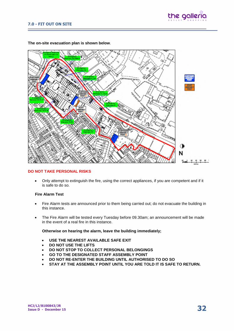
The on-site evacuation plan is shown below.
DO NOT TAKE PERSONAL RISKS
Only attempt to extinguish the fire, using the correct appliances, if you are competent and if itis safe to do so.
Fire Alarm Test
Fire Alarm tests are announced prior to them being carried out; do not evacuate the building inthis instance.
The Fire Alarm will be tested every Tuesday before 09.30am; an announcement will be madein the event of a real fire in this instance.
Otherwise on hearing the alarm, leave the building immediately;
USE THE NEAREST AVAILABLE SAFE EXIT DO NOT USE THE LIFTS DO NOT STOP TO COLLECT PERSONAL BELONGINGS GO TO THE DESIGNATED STAFF ASSEMBLY POINT DO NOT RE-ENTER THE BUILDING UNTIL AUTHORISED TO DO SO STAY AT THE ASSEMBLY POINT UNTIL YOU ARE TOLD IT IS SAFE TO RETURN.
7.0 - FIT OUT ON SITE
HCJ/LJ/B100843/JRIssue D - December 15 33
7.17 Prohibited materials or substances
Materials which are not to be used in the galleria:
1. High alumina cement.2. Woodwool slabs in permanent formwork to concrete or in structural elements.3. Calcium chloride admixtures for use in reinforced concrete.4. Asbestos and asbestos containing products as defined in the Asbestos Regulations
1987 or any statutory modification or re-enactment thereof.5. Asbestos substitutes or any naturally occurring or man-made mineral fibres
(including rock-wool or slag wool) with a thickness of 3 microns or less and alength of 200 microns or less or which contain any fibres not sealed or otherwisestabilised to prevent migration of fibres.
6. Aggregates for use in reinforced concrete which do not comply with BritishStandard 882:1992 and aggregate for use in concrete which do not comply withBritish Standard 8110:1985.
7. Lead, lead paint or any other materials containing lead which may be ingested,inhaled or absorbed, except where copper alloy fittings containing lead are specificallyrequired in drinking water pipework by any relevant statutory requirements.
8. Urea-formaldehyde, polyurethane, isocyanurates, polyisocyanurates in foams or othermaterials which may release gases in quantities which may be hazardous withreference to any limits set by the Health and Safety Executive.
9. Calcium silicate bricks or tiles.10. Vermiculite, unless it is established as being fibre-free.11. Any of the products containing cadmium which are referred to in the
Environmental Protection (Controls or Injurious Substances) (No.2) Regulations 1993or any amendment or re-enactment thereof.
12. Any timber treated with pentachlorophenol.13. Polytetrafluorethylene (known as PTFE) except when used as non-stick sealing within
valves or as an isolating tape.14. Materials which emit Radon gas.15. Insulation which uses chlorofluorocarbons (known as CFCs).16. Halon in fixed fire control systems (if a suitable alternative is available).17. Timber which is not obtained from a managed and regulated sustainable source.18. Any other materials or substances which are generally known at the time of
specification or approval to be deleterious or otherwise not in accordance with BritishStandards, Codes of Practice or good building practice or techniques.
8.0 - COMMISSIONING
HCJ/LJ/B100843/JRIssue D - December 15 34
8.1 Charges
All Retailers must pay the connection charges for connecting their engineering services intothe Landlord’s systems (sprinklers, fire alarm). The Landlord’s specialist Contractors who willundertake the works should be contacted at the earliest opportunity to confirm connectioncharges and programmes of works for their individual units.
8.2 Fire Alarm Connection Procedure
The Landlord’s fire alarm systems are maintained by Trinity Protection System Ltd andconnection to the Landlord’s systems can only be made by them to prevent potentialcorruption of the system.
Note: It is advisable for the sprinkler and fire alarm connections to be carried out by thespecialist Contractors at the same time on the same day. Retailers must manage thesetimings themselves.
1. Retailer to provide the correct trading name two weeks prior to testing to enable the frontend graphics to be amended.
2. Trinity Protection System Ltd to test Retailer cables for earth and continuity.
3. Trinity Protection System Ltd to connect Retailer’s cables to the Landlord’s interface.
4. Trinity Protection System Ltd tests/witnesses fire and fault signals to the security room.
5. Trinity Protection System Ltd witnesses the sprinkler alarm and isolate signal to thesecurity room.
6. All actions above will have to occur prior to the Retailer being allowed to open for trade.
Note: It is the Retailer’s responsibility to ensure that the system installed within the retail unitis compatible with the Landlord’s system. Failure to meet the compatibility requirements mayresult in a delay in opening of the retail unit and additional costs associated with abortivecommissioning visits. Unauthorised connection to the Landlord’s system may result indamage to the Landlord’s system. Any costs associated with damage caused byunauthorised connection will be charged to the Retailer.
8.3 Sprinkler Connection Procedure
The Landlord’s sprinkler system is maintained by the Blue Shield Fire Protection Ltd andincludes a monitored isolating valve and zone check flow switch. Connections to theLandlord’s system can only be made by the Blue Shield Fire Protection Ltd.
1. Sprinkler installation completed within unit demise. The Retailer’s installation is NOT tobe connected to the Landlord’s system without authorisation from Centre Management.
2. Retailer Sprinkler Contractor carries out Hydraulic test on installation to at least 15 bar forat least 2 hours.
3. Retailer’s Sprinkler Contractor completes application for connection form and submits toBlue Shield Fire Protection Ltd together with:-
Confirmation that payment for connection has been issued. LPCB LPS 1048 Certificate of Conformity. Sprinkler system Hydraulic test certificate. Provides evidence, issued by the Retailer’s insurer, confirming the installation has
been approved and is acceptable to the insurer.
8.0 - COMMISSIONING
HCJ/LJ/B100843/JRIssue D - December 15 35
Note: Copies of the above certificates are to be issued to the Retail DeliveryManager.
4. Retailer’s Sprinkler Contractor back-fills sprinkler system against closed Landlord’smonitored isolating valve to a water pressure of 10 bar.
5. Retailer Sprinkler Contractor co-ordinates with Blue Shield Fire Protection Ltd to open theretail unit’s isolating valve on a date to be mutually agreed. The Retailer’s SprinklerContractor is to be in attendance. It remains the Retailer’s responsibility to manage theopening of the valve. The Retailer is to ensure adequate notification is given to theLandlord/Centre Management on what date the valve is to be opened (so the fire alarminterface can be taken “off watch” to prevent false alarm).
6. Blue Shield Fire Protection Ltd issues certificate confirming Retailer is connected to theLandlord’s system and the valves are open.
Note: Specialist certificate to form part of the Step 4 submission.
8.4 Cold Water Connection Procedure
Retailer completes Domestic Water Supply installation within unit demise to a standardcompliant with all water supply regulation and Water Authority requirements. The Retailer’sinstallation is NOT to be connected to the incoming main without authorisation.
1. Retailer chlorinates system inside retail unit.
2. Retailer submits the following to Centre Management:-
Certification confirming pipework is sound and free from leaks. Certification confirming Retailer’s system has been chlorinated in accordance with BS
6700:2006. Issues certificate confirming installation conforms to all water supply By-Laws. Takes reading of water meter and issues reading to Retail Delivery Team.
3. Retailer demonstrates to Centre Management location of non-return valve.
4. Upon receipt of authorisation, Retailer connects internal pipe work to the incoming mainand turns on water supply. It is the Retailer’s responsibility to ensure all taps and valveswithin the unit are closed or off to ensure no flooding occurs.
8.5 Foul Drainage Connection Procedure
1. Retailer completes foul drainage installation within retail unit, undertakes air test and ensuresthis is witnessed by Building Control Officer. Test is to cover all pipework from top of stackthrough to lowest cleaning/rodding point.
2. Retailer provides a certificate to Centre Management confirming the installation is completeand has been witnessed by Building Control prior to connection to the Landlord’s system.
9.0 - CONSENT TO TRADE
HCJ/LJ/B100843/JRIssue D - December 15 Index36
9.0 CONSENT TO TRADEThe unit will not be allowed to open for trade without a ‘Consent to Trade’ form signed off by the RetailDelivery Manager confirming receipt of the necessary documentation. The Consent to Tradesubmission form should be submitted to the Retail Delivery Manager at least 5 working days prior tothe anticipated store opening date.
Within 28 days from the store opening the Retailer is to provide 1 hard copy set of all as builtinformation toether with 3 full electronic versions on CD to be issued to the Retail Delivery Managerr.This is to incorporate:-
1. As built drawings (dwg/pdf formats)
2. Health & Safety File
3. Operational and Maintenance Manuals
4. Test & commissioning certificates
5. Statutory approvals