RESURFACING WITH PORTLAND CEMENT CONCRETE
100
NATIONAL COOPERATIVE HIGHWAY RESEARCH PROGRAM 99 SYNTHESIS OF HIGHWAY PRACTICE RESURFACING WITH PORTLAND CEMENT CONCRETE S a a TRANSPORTATION RESEARCH BOARD NATIONAL RESEARCH COUNCIL S
Transcript of RESURFACING WITH PORTLAND CEMENT CONCRETE

NATIONAL COOPERATIVE HIGHWAY RESEARCH PROGRAM 99 SYNTHESIS OF HIGHWAY PRACTICE
RESURFACING WITH PORTLAND CEMENT CONCRETE
S
a
a
TRANSPORTATION RESEARCH BOARD NATIONAL RESEARCH COUNCIL
S

TRANSPORTATION RESEARCH BOARD EXECUTIVE COMMITTEE 1982
Officers
Chairman
DARRELL V MANNING, Director, Idaho Transportation Department
Vice Chairman
LAWRENCE D. DAHMS, Executive Director. Metropolitan Transportation Commission. San Francisco Bar Area
Secretary
THOMAS B. DEEN, Executive Director, Transportation Research Board
Members
RAY A. BARNHART, Federal High way Administrator. U.S. Department of Transportation (cx officio)
FRANCIS B. FRANCOIS, Executive Director. American Assc,ciatic,n of State Highway and Transportation Officials (cx officio)
WILLIAM J. HARRIS, JR., Vice President for Research and Test Department, Association of American Railroads (cx officio)
J. LYNN HELMS, Federal Aviatic,n Administrator. U.S. Department of Transportation (cx officio)
THOMAS D. LARSON, Secretary, Pennsylvania Department of Transportation (cx officio, Past Chairman (1981)
RAYMOND A. PECK, JR., National Highway Traffic Safety Administrator, U.S. Department of Transportation (cx officio)
ARTHUR E. TEELE, JR., Urban Mass Transportation Administratc,r, U.S. Department of Transportation (cx officio)
CHARLEY V. WOOTAN, Director, Texas Transportation Institute, Texas A&M University (cx officio, Past Chairman 1980)
GEORGE J. BEAN, Director of Aviation. Hillsborough Count (Florida) Aviation Authority
JOHN R. BORCHERT, Professor, Department of Geography, University of Minnesc,ta
RICHARD P. BRAUN, Commissioner, Minnesota Department of Transportation
ARTHUR J. BRUEN, JR., Vice President, Cc,ntinental illinois Natic,na! Bank and Trust Company of c'hicago
JOSEPH M. CLAPP, Senior Vice President, Roadway Express, Inc.
ALAN G. DUSTIN, President and Chief Executive Officer, Boston and Maine Cc,rpc,ration
ROBERT E. FARRIS, Commissioner, Tennessee Department of Transportation
ADRIANA GIANTURCO, Directc,r, California Department of Transportation
JACK R. GILSTRAP, Executive Vice President, American Public Transit Association
MARK G. GOODE, Engineer-Director, Texas State Department of Highways and Public Transportation
WILLIAM C. HENNESSY, Commissioner, New Yc,rk State Department of Transportation
LESTER A. HOEL, Chairman, Department of Civil Engineering, University of Virginia
MARVIN L. MANHEIM, Professor, Department of ('ivil Engineering, Massachusetts Institute of Technolc,gy
FUJIO MATSUDA, President, University of Hawaii
DANIEL T. MURPHY, County Executive, Oakland County Courthc,use, Michigan
ROLAND A. OUELLE'VFE, Director of Transportation Affairs, Gc'neral Motors Corporation
RICHARD S. PAGE, Gc'neral Manager, Washington (D.C.) Metropolitan Area Transit Authority
MILTON PIKARSKY. Director of Transportation Research. Illinois Institute of Technology
GUERDON S. SINES, Vice President, Information and Control Systems. Missc,uri Pacific Railroad
JOHN E. STEINER, Vice President, Corporatc' Product Development. The Boeing Company
RICHARD A. WARD, Director-Chief Engineer, Oklahoma Department of Transportation
NATIONAL COOPERATIVE HIGHWAY RESEARCH PROGRAM
Transportation Research Board Executive Cc,mmittee Subconcmittee for NCHRP
DARRELL V MANNING, Idaho Transp. Dept. (Chairman) JACK R. GILSTRAP, American Public Transit Associatic,n LAWRENCE D. DAHMS, Metropolitan Transportation Commission RICHARD S. PAGE, Washington Metropolitan Area Transit Authority WILLIAM J. HARRIS, JR., Associatic,n of American Railroads THOMAS D. LARSON, Pennsylvania Dept. of Transportation ARTHUR E. TEELE, JR., Urban Mass Transportation Administratic,n THOMAS B. DEEN, Transportation Research Board
Field of Special Projects
Prc,jc'ct Cc,mmittee SP 20-5
RAY R. BIEGE, JR., Cc,nsultant (Chairman)
VERDI ADAM, Louisiana Dept. of Transp. and Development
ROBERT N. BOTH MAN, Oregon Dept. of Transportation
JACK H. DILLARD, Virginia Hc,'v. and Transp. Research Council
JACK FRIEDENRICH, New Jerser Dept. of TransportationDAVID GEDNEY, Dc' Lc'uw, Cather and Company
SANFORD P. LAHUE, Federal Highway Administration
BRYANT MATHER, USAE Waterways Experiment Static,n
THOMAS H. MAY, Pennsylvania Dept. of Transportation
THEODORE F. MORF, Consultant
EDWARD A. MUELLER,Jacksonville Trnsp. Authority
ROBERT J. BETSOLD, Federal High cvay Administratic,n
K. B. JOHNS, Transportation Research Board
Program Staff
KRIEGER W. HENDERSON, JR., Directc,r, Cooperative Research Programs
LOUIS M. MACGREGOR, Administrative Engineer CRAWFORD F. JENCKS, Projects Engineer
R. IAN KINGHAM, Projects Engineer
ROBERT J. REILLY, Projects Engineer
HARRY A. SMITH, Projects Engineer
ROBERT E. SPICHER, Projects Engineer
HELEN MACK, Editc,r
TRB Stafffor NCHRP Project 20-5
DAMIAN J. KULASH, Assistant Directc,r for Special Prcjc'cts
THOMAS L. COPAS, Special Projects Engineer
HERBERT A. PENNOCK, Special Projects Engineer
NANCY A. ACKERMAN. Editor
NATIONAL COOPERATIVE HIGHWAY RESEARCH PROGRAM SYNTHESIS OF HIGHWAY PRACTICE 99
RESURFACING WITH PORTLAND CEMENT CONCRETE
RONALD L. HUTCHINSON
Vicksburg, Mississippi
Topic Panel
EDWIN C. LOKKEN, Portland Cement Association
RICHARD W. MAY, Federal Highway Administration
KENNETH H. MCGHEE, Virginia Highway and Transportation Research Council
GERALD B. PECK, Texas Department of Highways and Public Transportation
LAWRENCE F. SPAINE, Transportation Research Board
REUBEN S. THOMAS, Federal Highway Administration
RESEARCH SPONSORED BY THE AMERICAN ASSOCIATION OF STATE HIGHWAY AND TRANSPORTATION OFFICIALS IN COOPERATION WITH THE FEDERAL HIGHWAY ADMINISTRATION
TRANSPORTATION RESEARCH BOARD NATIONAL RESEARCH COUNCIL WASHINGTON, D.C. DECEMBER 198

NATIONAL COOPERATIVE HIGHWAY RESEARCH PROGRAM NCHRP SYNTHESIS 99
Systematic, well-designed research provides the most effec-tive approach to the solution of many problems facing high-way administrators and engineers. Often, highway problems are of local interest and can best be studied by highway departments individually or in cooperation with their state universities and others. However, the accelerating growth of highway transportation develops increasingly complex prob-lems of wide interest to highway authorities. These problems are best studied through a coordinated program of coopera-tive research.
In recognition of these needs, the highway administrators of the American Association of State Highway and Transpor-tation Officials initiated in 1962 an objective national highway research program employing modem scientific tech-niques. This program is supported on a continuing basis by funds from participating member states of the Association and it receives the full cooperation and support of the Federal Highway Administration, United States Department of Transportation.
The Transportation Research Board of the National Re-search Council was requested by the Association to ad-minister the research program because of the Board's recog-nized objectivity and understanding of modem research practices. The Board is uniquely suited for this purpose as: it maintains an extensive committee structure from which authorities on any highway transportation subject may be drawn; it possesses avenues of communications and cooper-ation with federal, state, and local governmental agencies, universities, and industry; its relationship to its parent orga-nization, the National Academy of Sciences, a private, non-profit institution, is an insurance of objectivity; it maintains a full-time research correlation staff of specialists in highway transportation matters to bring the findings of research directly to those who are in a position to use them.
The program is developed on the basis of research needs identified by chief administrators of the highway and trans-portation departments and by committees of AASHTO. Each year, specific areas of research needs to be included in the program are proposed to the Academy and the Board by the American Association of State Highway and Transporta-tion Officials. Research projects to fulfill these needs are defined by the Board, and qualified research agencies are selected from those that have submitted proposals. Adminis-tration and surveillance of research contracts are the respon-sibilities of the Academy and its Transportation Research Board.
The needs for highway research are many, and the Na-tional Cooperative Highway Research Program can make significant contributions to the solution of highway transpor-tation problems of mutual concern to many responsible groups. The program, however, is intended to complement rather than to substitute for or duplicate other highway re-search programs.
NOTE: The Transportation Research Board, the National Academy of Sciences, the Federal Highway Administration, the American Association of State Highway and Transportation Officials, and the individual States pai-tici-pating in the National Cooperative Highway Research Program do not endorse products or manufacturers. Trade or manufacturers' names appear herein solely because they are considered essential to the object of this report.
Project 20-5 FY 1981 (Topic 13-04)
ISSN 0547-5570
ISBN 0-309-03460-4
Library of Congress Catalog Card Number 82-74311
Price: $8.40
Subject Areas Pavement Design and Performance Cement and Concrete Construction
Modes Highway Transportation Air Transportation
NOTICE
The project that is the subject of this report was a part of the National Cooper-ative Highway Research Program conducted by the Transportation Research Board with the approval of the Governing Board of the National Research Council, acting in behalf of the National Academy of Sciences. Such approval reflects the Governing Board's judgment that the program concerned is of national importance and appropriate with respect to both the purposes and resources of the National Research Council.
The members of the technical committee selected to monitor this project and to review this report were chosen for recognized scholarly competence and with due consideration for the balance of disciplines appropriate to the project. The opinions and conclusions expressed or implied are those of the research agency that performed the research, and, while they have been accepted as appropriate by the technical committee, they are not necessarily those of the Transportation Research Board, the National Research Council, the National Academy of Sciences, or the program sponsors.
Each report is reviewed and processed according to procedures established and monitored by the Report Review Committee of the National Academy of Sciences. Distribution of the report is approved by the President of the Acad- emy upon satisfactory completion of the review process. -
The National Research Council was established by the National Academy of Sciences in 1916 to associate the broad community of science and tech-nology with the Academy's purposes of furthering knowledge and of advising the Federal Government. The Council operates in accordance with general policies determined by the Academy under the authority of its congressional charter of 1863, which establishes the Academy as a private, nonprofit, self-governing membership corporation. The Council has become the principal operating agency of both the National Academy of Sciences and the National Academy of Engineering in the conduct of their services to the government, the public, and the scientific and engineering communities. It is administered jointly by both Academies and the Institute of Medicine. The National Acad-emy of Engineering and the Institute of Medicine were established in 1964 and 1970, respectively, under the charter of the National Academy of Sciences.
The Transportation Research Board evolved from the 54-year-old Highway Research Board. The TRB incorporates all former HRB activities and also performs additional functions under a broader scope involving all modes of transportation and the interactions of transportation with society.
Published reports of the
NATIONAL COOPERATIVE HIGHWAY RESEARCH PROGRAM
are available from:
Transportation Research Board National Academy of Sciences 2101 Constitution Avenue, N.W. Washington, D.C. 20418
Printed in the United States of America.

PREFACE A vast storehouse of information exists on nearly every subject of concern to highway administrators and engineers. Much of this information has resulted from both research and the successful application of solutions to the problems faced by practitioners in their daily work. Because previously there has been no systematic means for compiling such useful information and making it available to the entire highway community, the American Association of State Highway and Transporta-tion Officials has, through the mechanism of the National Cooperative Highway Research Program, authorized the Transportation Research Board to undertake a continuing project to search out and synthesize useful knowledge from all avail-able sources and to prepare documented reports on current practices in the subject areas of concern.
This synthesis series reports on various practices, making specific recommen-dations where appropriate but without the detailed directions usually found in handbooks or design manuals. Nonetheless, these documents can serve similar purposes, for each is a compendium of the best knowledge available on those measures found to be the most successful in resolving specific problems. The extent to which these reports are useful will be tempered by the user's knowledge and experience in the particular problem area.
FOREWORD This synthesis report will be of special interest to pavement designers, materials
By Staff engineers, and other seeking information on portland cement concrete overlays placed over both concrete and asphalt pavements. Detailed information is pre-
Research Board Transportation
sented on design, construction, and performance of such overlays.
Administrators, engineers, and researchers are continually faced with highway problems on which much information exists, either in the form of reports or in terms of undocumented experience and practice. Unfortunately, this information often is scattered and unevaluated, and, as a consequence, in seeking solutions, full information on what has been learned about a problem frequently is not assembled. Costly research findings may go unused, valuable experience may be overlooked, and full consideration may not be given to available practices for solving or alleviating the problem. In an effort to correct this situation, a continu-ing NCHRP project, carried., out by the Transportation Research Board as the research agency, has the objective of reporting on common highway problems and synthesizing available information. The synthesis reports from this endeavor con-stitute an NCHRP publication series in which various forms of relevant informa-tion are assembled into single concise documents pertaining to specific highway problems or sets of closely related problems.

Various types of portland cement concrete overlays are used to resurface existing pavements. The types in use include bonded and unbonded, reinforced and unreinforced, and a variety of thicknesses. This report of the Transportation Research Board includes useful information on design and construction practices and on evaluation of available performance data.
To develop this synthesis in a comprehensive manner and to ensure inclusion of significant knowledge, the Board analyzed available information assembled from numerous sources, including a large number of state highway and transpOr-tation departments. A topic panel of experts in the subject area was established to guide the researcher in organizing and evaluating the collected data, and to review the final synthesis report.
This synthesis is an immediately useful document that records practices that were acceptable within the limitations of the knowledge available at the time of its preparation. As the processes of advancement continue, new knowledge can be expected to be added to that now at hand.

CONTENTS
SUMMARY
3 CHAPTER ONE INTRODUCrI0N
History of Resurfacing, 3 Interfaces, 4 Types and Uses of Concrete Resurfacings, 5 Resurfacing Projects, 6
7 CHAPTER TWO DESIGN AND CONSTRUCTION PRACTICES
Evaluation of Existing Pavement, 7 Existing Pavement Preparation, 9 Interface Medium Design and Construction, 11 Thickness Requirements, 12 Concrete Mixture Proportions, 19 Reinforcement, 21 Jointing, 23 Placement, Finishing, and Curing, 25
27 CHAPTER THREE SUMMARY OF CONCRETE RESURFACING EXPERIENCE AND PERFORMANCE
Bonded Concrete Resurfacings, 27 Partially Bonded Concrete Resurfacings, 39 Unbonded Concrete Resurfacings, 43 Concrete Resurfacing of Flexible and Other Types
of Pavements, 50
54 CHAPTER FOUR TRAFFIC-DELAY ASSESSMENT IN THE SELECTION OF TYPE OF RESURFACING
Existing Pavement Preparation Time, 54 Resurfacing Layer Placement Time, 55 Miscellaneous Construction Time, 55 Actual Examples of Project Traffic-Handling Methods, 55
57 CHAPTER FIVE CONCLUSIONS AND RECOMMENDATIONS
Conclusions, 57 Recommendations, 60
62 REFERENCES
66 BIBLIOGRAPHY
67 APPENDIX A RESURFACING PROJECTS
89 APPENDIX B MODIFIED EMPIRICAL RESURFACING DESIGN EQUATIONS
ACKNOWLEDGMENTS
This synthesis was completed by the Transportation Research Board under the supervision of Damian J. Kulash, Assistant Director for Special Projectsi The Principal Investigators responsible for con-duct of the synthesis were Thomas L. Copas and Herbert A. Pen-nock, Special Projects Engineers. This synthesis was edited by Nancy A. Ackerman.
Special appreciation is expressed to Ronald L. Hutchinson, Vicks-burg, Mississippi, who was responsible for the collection of the data and the preparation of the report.
Valuable assistance in the preparation of this synthesis was pro-vided by the Topic Panel, consisting of Edwin C. Lokken, Principal Highway Engineer, Portland Cement Association; Richard W. May, Highway Research Engineer, Office of Highway Research, Federal Highway Administration; Kenneth H. McGhee, Research Engineer, Virginia Highway and Transportation Research Council; Gerald B. Peck, Engineer of Pavement Design, Texas Department of High-ways and Public Transportation; and Reuben S. Thomas, Highway Engineer, Office of Engineering, Federal Highway Administration.
Lawrence F. Spaine, Engineer of Design, Transportation Re-search Board, assisted the NCHRP Project 20-5 Staff and the Topic Panel.
Information on current practice was provided by many highway and transportation agencies. Their cooperation and assistance were most helpful.

RESURFACING WITH PORTLAND CEMENT CONCRETE
SUMMARY Portland cement concrete has been used to resurface existing pavements since about 1913. Performance data indicate that a relatively low-maintenance service life of 20 years can be expected and that many resurfacings have provided 30 to 40 years of service. Although used in practically every state, portland cement concrete resurfacings have not been used as widely as asphalt concrete resurfac-ings because of higher initial cost and construction complexity. Several develop-ments within the last 10 to 15 years have caused the states to reevaluate the use of portland cement concrete resurfacings:
Improvements in construction equipment and procedures; Improved reinforcing techniques, such as continuous reinforcement, fibrous
reinforcement, and prestressing; The uncertain future of asphalt supply and its rapidly increasing cost; and The trend toward selection of resurfacing type based on life-cycle costs
rather than initial costs.
Portland cement concrete offers a wide range of resurfacing alternatives includ-ing five types of resurfacing [plain (unreinforced) concrete, conventionally rein-forced concrete, continuously reinforced concrete, fibrous concrete, and pre-stressed concrete], which can be used with three interfaces (bonded, partially bonded, and unbonded). This permits the design engineer to tailor the resurfacing to the type and condition of the existing pavement as well as to its intended future use. Unbonded plain, conventionally reinforced, and continuously reinforced concrete resurfacings have been widely used for highways, whereas partially bonded plain and conventionally reinforced concrete resurfacings have been used extensively for airfields. Recent developments in surface cleaning techniques have resulted in new emphasis on the use of thin, bonded plain concrete resur-facings, especially when the primary need for resurfacing is to improve the rideability or surfacing texture of the existing pavement. Fibrous reinforcement and prestressing offer new ways to strengthen the concrete and resist cracking; however, their use as resurfacings has been minimal and they must be considered to be in the experimental or developmental stage.
For recently constructed portland cement concrete resurfacings, there has been more emphasis on a thorough evaluation and preparation of the existing pavement. Many agencies have found that the location ind repair of low-strength or distressed areas in the existing pavement can add years of service life to the

2
resurfacing. There is no universally accepted thickness design procedure for portland cement concrete resurfacings. Empirically developed relationships (which relate resurfacing thickness to the deficiency between the required mono-lithic thickness of concrete and existing pavement thickness) are available and have been used extensively for airfields but sparingly for highways. Several theoretically based thickness design procedures have been advanced and a few are currently under evaluation; however, none has been universally accepted.
Minimum thickness requirements for portland cement concrete resurfacings vary among agencies; however, minimum thicknesses of 2 to 3 in. (50 to 75 mm) for bonded resurfacings and 5 to 7 in. (125 to 175 mm) for partially bonded or unbonded resurfacings appear to be most common.
A major problem with portland cement concrete resurfacing is reflection cracking (sometimes referred to as sympathetic cracking). Thermal movements and load-induced deflections at joints or cracks in the existing pavement can cause cracking to occur through the resurfacing, which in turn creates potential maintenance problems. The various resurfacing alternatives permit the selection and design of a resurfacing type and interface that will minimize these detrimental effects.
Future research needs include continuing development of a resurfacing thick-ness design method and additional data on the characteristics of bonded resurfac-ings, fibrous concrete, and prestressed concrete under repeated load applications and environmental effects. Additional data are needed to better define the desirable properties of the unbonding medium when a separation of the resurfac-ing and existing pavement is needed.

CHAPTER ONE
INTRODUCTION
This synthesis is concerned with the resurfacing of existing portland cement concrete (rigid) and bituminous cement cop-crete (flexible) pavements with portland cement concrete (hereinafter referred to as "concrete"). Concrete resurfac-ings have been used for one or more of the following pur-poses: (a) to restore the rideabiity of the existing pavement, (b) to provide an appropriate surface texture to the existing pavement, or (c) to restore or increase the load-carrying capacity or life or both ofthe existing pavement. The term "resurfacing" is considered inclusive of all these purposes and is used throughout this synthesis instead of the fre-quently used term "overlay." This report deals primarily with highway experience, but city street, county road, and airfield experience have been included where it has been considered to be appropriate.
Because a Highway Research Board (HRB) bibliography (1, 2) covers publications on this subject through 1962 and because results of condition surveys of continuously rein-forced concrete overlays in 1975 (3) and of concrete resurfac-ing in 1977 (4) have been previously published, the major emphasis here is on concrete resurfacing practices within the last 10 to 15 years. In preparation for this synthesis, a review of the literature was conducted, and it was determined that an adequate cross section of practices that have been used was available. Therefore, published papers and articles have been used as the primary source of information. Personal interviews, telephone inquiries, and selected field visits were used to supplement the published data, especially in the eval-uation of the performance of the various types of concrete resurfacings that have been used.
The references included herein supplement the HRB bib-liography (1, 2) and, although not inclusive of all articles published on this subject, they are considered representative of the various concrete resurfacing strategies that have been employed. A perusal of the references reveals a large number of variables in the materials and construction processes that have been used and forms the basis for the description of resurfacings contained herein. A summary of the construc-tion and performance of selected resurfacings, as gleaned from published reports and articles and supplemented by personal contacts, is presented in Chapter 3. The chapter on design and construction considerations is intended to present a consensus of what is considered good practice instead of a complete documentation of all procedures that have been developed or used. The concluding chapter is a summary including recommendations for the selection and use of con-crete resurfacings and future research needs.
HISTORY OF RESURFACING
The network of vehicular pavements in this country, from city streets, farm-to-market roads, the primary highway system, to the Interstate system, has been developed through a continual process of construction. These pavements, al-though adequate when constructed, soon experienced in-creased loadings in terms of both numbers and weight. The same is true of the nation's airfield pavements, both civil and military, where there has been an even more rapid increase in loadings, especially in the weights of aircraft; These in-creases in the numbers and weight of applied loading, when combined with the adverse effects of the environment on the performance of construction materials, have resulted in var-ious states of distress. The fact that the pavement network plays an important role in the nation's economy can hardly be questioned, and this has led to a continual search for ways to economically maintain the pavement system with minimal disruption to the traffic flow.
Concrete resurfacing as a method of extending the life of anexisting pavement is not new; it was used as early as 1913 and 1914. Most state highways and city streets were orig-inally constructed with 4 to 6 in. (100 to 150 mm) of concrete or a comparable thickness of flexible pavement. Several of those early concrete pavements were reinforced and of long-panel design. As the numbers and weights of vehicles in-creased, local governments had to add 4 to 6 in. of concrete to increase the load-carrying ability and thus extend the life of the existing pavement. Because cracking developed in the long-panel reinforced concrete base pavements, many resur-facings were reinforced and most were constructed with a separation course to minimize reflection cracking. Several separation course materials were used, but the most common was some form of bituminous material. During this same period (pre-World War II), a few agencies experimented with the use of ito 3 in. (25 to 75 mm) of concrete bonded to the existing pavement when just a resurfacing was needed.
Out of necessity, pavement rehabilitation during World War II was minimal; with an increase in the volume and weight of truck traffic during this period, a tremendous back-log of vehicular pavement rehabilitation work developed. It was obvious that priority needed to be given to upgrading the nation's pavement network. Many of the original pavements had been constructed with lanes 8- to 10-ft (2.4- to 3-rn) wide, and these had to be widened as well as resurfaced. Concrete played an important role in this rehabilitation; however, it was during this period that bituminous concrete resurfacing

received the most attention because it produced a dramatic improvement in the rideability of the existing surface and could be constructed with less disruption to the traffic flow. In addition, bituminous resurfacing could be constructed thinner than concrete resurfacing, thus reducing the initial cost. Experience had shown that a minimum concrete thick-ness of 4 or 5 in. (100 or 125 mm) was necessary to prevent excessive cracking due to curling or warping unless the sur-facing could be bonded to the existing pavement.
During and immediately following World War II, concrete resurfacing played an important role in the continual upgrad-ing of military airfield pavements. Many of the original air-field pavements were constructed of 8 to 10 in. (200 to 250 mm) of plain (unreinforced) or reinforced concrete generally using standard highway practices. With the rapid increase in aircraft weight and traffic, these original pavements soon had to be resurfaced to increase load-carrying ability. During this period, an extensive research program was carried on by the Corps of Engineers to develop methodology for the design of concrete resurfacing. Criteria were developed for the use of either plain or reinforced concrete resurfacing, but most projects were completed using plain concrete.
Concrete resurfacing has also played an important role in upgrading existing airport pavements for the civil aviation industry. Civil aircraft closely followed the growth in military aircraft through the 1950s; however, unlike military aircraft, civil aircraft continued to increase in both volume and weight through the 1960s and 1970s. Civil airport pavements were originally constructed of 6 to 10 in. (150 to 250 mm) of concrete and had to be resurfaced to accommodate the in-creasing aircraft weights. Concrete resurfacings of civil air-port pavements have been primarily plain concrete, designed and constructed using the criteria developed for military pavements.
Since inauguration of the Interstate highway system in 1956, priority has been given to the construction of this system and until recently there has been less emphasis on the resurfacing of the existing network of highways. In some cases, in the construction of Interstate highways, existing stretches of primary highway pavement could be utilized generally through widening or resurfacing or both. Although concrete was used extensively in the construction of the Interstate highway system, there was little use of it as a resurfacing medium; most agencies preferred bituminous concrete. However, considerable progress was being made in the design and construction of concrete pavements. Central-mix batch plants, electronically controlled slip-form payers, improved concrete spreaders, and improved finish-ing techniques made it possible, economically, to pave a mile (1.6 km) of smooth two-lane pavement per day.
As the Interstate highway system nears completion, many sections that are 15 years old or more are in need of major repair or resurfacing. Improvements made in concrete con-struction technology and equipment, increased cost of bi-tuminous materials, emphasis on crude oil conservation, and increasing environmental constraints have resulted in a re-surgence in the consideration of concrete for resurfacing. Vyce (5) states:
This resurgence was instigated both by new designs and de-creased demand for concrete materials. The designs have in-volved continuous or fiber reinforcement, the former being intended for new construction. However, with the Interstate
system nearing completion, new construction is decreasing significantly, with emphasis shifting to rehabilitation. Con-crete advocates have turned their attention to overlays, aided by two additional developments—the uncertain future supply of asphalt and the service life of asphalt overlays on concrete. While both are subject to interpretation and evaluation by individual agencies, the supply problem is more a matter of time. Performance, on the other hand, is subjective. Each agency has its own criterion for adequate service—i.e. what is expected of an overlay on a given pavement in terms of performance and life. Thus, each agency may evaluate the economic advantages and disadvantages of concrete overlays differently.
Many highway engineers have begun to base their recom-mendations regarding resurfacing on a total-cost economic analysis, which includes initial cost, maintenance and repair costs, and present worth of future resurfacings during the life of the resurfacing. These are often presented in terms of "annualized costs." Vyce (5) states:
The most important consideration is cost. While the price of asphalt has increased more than concrete over the past few years, there is still a considerable gap. However, this gap may continue to narrow as world supplies of petroleum decrease. In addition, initial cost should not be the primary criterion: long-term performance must be considered.
This thinking is not limited to state highway engineers; Schnoor and Renier (6) state:
During the past 10 years, several county engineers in Iowa have begun to reanalyze the economics of resurfacing proce-dures used on their asphalt-paved secondary roads in an attempt to decrease maintenance costs and lengthen the re-quired maintenance cycle. Their analysis has resulted in the construction of portland cement concrete overlays over old asphalt county roads . . . in a number of counties.
The resurgence in the consideration of concrete resurfac-ing is evidenced by the number of concrete resurfacing proj-ects that have been constructed in the last 10 years. Although some of this increased activity can be attributed to emphasis being placed on the Federal Highway 4-R program of reha-bilitation, restoration, resurfacing, and reconstruction, other factors, such as the use of continuously reinforced concrete, fibrous concrete, and prestressed concrete as potential resur-facing materials and the development of improved bonding techniques, have broadened the application of concrete re-surfacings and attracted the attention of engineers. Recently, resurfacings, using many of these materials and construction techniques, have been constructed as test or trial sections to collect data for the extensive pavement resurfacing program facing the highway engineer in the future.
Recent innovations in construction equipment, especially in surface-milling machines, have resulted in renewed inter-est in the use of thin bonded-concrete resurfacings to up-grade existing pavements. Because of these recent develop-ments, bonded resurfacing has been given more attention in this synthesis than have the other types of resurfacing, which have remained essentially unchanged over the last several years insofar as construction techniques are concerned.
INTERFACES
Experience has shown that the performance of a resurfac-ing can be influenced by the condition of the existing pave-ment, which can vary from structurally sound to badly dis-
tressed at the time of resurfacing. There are three primary interfaces (i.e., treatment between the resurfacing and the existing pavement) that are used for concrete resurfacing. These are characterized by the degree of bond between the existing pavement and the resurfacing and, as used herein, are termed bonded, partially bonded, and unbonded. They are also sometimes referred to as monolithic, direct, and separated or nonbonded. The interface used will depend on the design and condition of the existing pavement and will affect the design and construction of the resurfacing. The interfaces have been described in many published articles (5, 7-10), but are repeated herein for clarity.
Bonded Interface
Specific procedures, including meticulous cleaning of the existing pavement, application of a bonding medium, careful placement and consolidation of the resurfacing concrete, and thorough protection throughout the cure period, are followed during preparation of the existing pavement and resurfacing construction to ensure complete bond resulting in a mono-lithic structure. Some minor adjustments may be necessary in the concrete mixture to achieve a dense, durable surface. Joints must be provided in the bonded resurfacing coinciding with those in the existing pavement to minimize uncontrolled cracking. Intermediate cracks in the existing pavement can be expected to reflect through the resurfacing.
used when the existing surface is badly distorted. Concrete may also be used to resurface existing concrete pavements that have previously received two or more asphalt concrete resurfacings resulting in a thick [4 in. (100 mm) or more] interlayer. Thick (4 in. or more) granular layers (crushed stone or stabilized aggregate) or cement-treated materials have sometimes been used as interlayers. Although these resemble unbonded resurfacings, thick interlayers make the design analysis more difficult. Finally, the existing concrete may be broken up and an unbonding medium applied before a concrete resurfacing. These are considered to be special interfaces and are not discussed in depth in the synthesis.
TYPES AND USES OF CONCRETE RESURFACINGS
Concrete resurfacings include plain concrete and all types of reinforced concrete. Although the predominant type of resurfacing has been plain (unreinforced) and conventionally reinforced concrete, a review of past practices reveals that there have been few, if any, standards established regarding the selection of resurfacing types.Jnstead, it appears that the final selection of resurfacing type is the result of local ex-perience, evaluation of the condition of existing pavement, the causes of the distress mechanism leading to the need for a resurfacing, and an economic analysis. Nevertheless, past practices have led to the identification of certain factors help-ful in the selection of resurfacing type. These factors are described for each of the resurfacing types that can be used.
Partially Bonded Interface
No special attempt to achieve or prevent bond between the resurfacing and existing pavement is required. Minimal sur-face preparation is necessary and normal concrete mixtures, construction practices, and curing procedures are used. Joints in the resurfacing coinciding with or located within 12 in. (300 mm) of joints in the existing pavement are required to minimize uncontrolled cracking. If the existing pavement is of long-panel design [more than 20 ft (6 m)], intermediate joints or reinforcement are desirable in the resurfacing to minimize the effects of reflection cracking. Intermediate cracks in the existing pavement can be expected to reflect through the resurfacing.
Unbonded Interface
A positive separation course (unbonding medium) is used between the existing pavement and resurfacing. Normal pav-ing concrete mixtures, construction methods, jointing layouts, and curing procedures are used for the resurfacing.
Other Interfaces
Concrete may be used to resurface existing flexible pave-ments. Generally, the concrete resurfacing is cast directly on the existing flexible pavement; however, portions of the existing flexible pavement may be removed and replaced with concrete (inlay resurfacing). Leveling courses may be
Plain Concrete
Plain (unreinforced) concrete may be combined with each of the three interfaces to resurface existing concrete pave-ments. Joints must be provided in bonded plain concrete resurfacings coincident with joints in the existing pavement (i.e., like joints over like joints) to prevent reflection cracking in the resurfacing. For partially bonded plain concrete resur-facings, joints that match or fall within 12 in. (300 mm) of joints in the existing pavement must be provided; however, it is not necessary that like joints be over like joints. Inter-mediate cracking in the existing pavement will normally cause reflection cracking in either a bonded or partially bonded plain concrete resurfacing. For these reasons, both bonded or partially bonded plain concrete resurfacings are generally restricted to structurally sound existing pave-ments. When unbonded plain concrete resurfacing is used, there is no requirement to match joints in the existing pave-ment because the unbonding medium effectively minimizes reflection cracking. For this reason, unbonded plain concrete resurfacings are generally used when the existing pavement is distressed or when it is not economically feasible to match joints.
It is generally considered that thin [4 in. (100 mm) or less] plain concrete resurfacings must be bonded to existing pave-ment to minimize distress in the resurfacing caused by warp-ing. Thin, bonded plain concrete resurfacings are normally used to restore the rideabiity or surface texture of existing structurally sound concrete pavements. Although a thicker• bonded plain concrete resurfacing can be used to strengthen an existing pavement, the required thickness will generally

be such that a partially bonded or unbonded resurfacing is practical, and probably more economical because of the lower cost for surface preparation and construction.
Conventionally Reinforced Concrete
Reinforced concrete, which contains distributed steel in the panels, may be combined with each of the three inter-faces to resurface existing concrete pavements. For bonded resurfacing, joints must be provided in the resurfacing that are coincident with those in the existing pavement (i.e., like joints over like joints). The matching of joints in a partially bonded reinforced concrete resurfacing and the existing pavement is a preferred practice but not essential, because the reinforcement will control reflection cracks that develop in the resurfacing. The word "control" in this context means that the reinforcement will prevent excessive movement at the crack and thus provide good service with a minimum of maintenance required. Similarly, the reinforcement will con-trol reflection cracking resulting from intermediate cracking in the existing pavement, making it possible to resurface distressed pavements with both bonded and partially bonded reinforced concrete. Unbonded reinforced concrete resur-facing is used when the existing pavement is badly distressed or distorted and a leveling course is needed.
As is the case with plain concrete, it is generally believed that thin [4 in. (100 mm) or less] reinforced concrete resurfac-ing should be bonded to the existing pavement to minimize distress due to warping. Thin, bonded reinforced concrete resurfacings may be used to restore ndeability or surface texture to existing pavements that are not badly distressed or distorted. Partially bonded or unbonded resurfacings are nor-mally used to restore or increase the load-carrying ability of an existing pavement. The unbonded interface is used when leveling courses are needed or the existing pavement has been badly distorted. Partially bonded and unbonded rein-forced concrete resurfacings are also used when the match-ing of joints required for plain concrete resurfacing is not economically feasible. This latter condition is especially true for airfield pavements. Similarly, airfield pavement criteria permit a reduction in the required concrete thickness through the use of reinforcement, which can make the use of rein-forced concrete resurfacing economically competitive with plain concrete resurfacing.
Continuously Reinforced Concrete
Continously. reinforced concrete (CRC) contains continu-ous longitudinal steel reinforcement with no intermediate transverse joints. Transverse reinforcement may or may not be used. From both design and construction standpoints, bonded CRC resurfacings do not seem practical and none is known to have been constructed. Minimum thickness, steel requirements, and jointing requirements for CRC resurfac-ings are essentially the same as for CRC pavements. Partially bonded and unbonded CRC resurfacings are used to restore the rideabiity and to increase the load-carrying capacity of existing pavements. CRC resurfacings are particularly appli-cable for existing pavements exhibiting structural distress and when it is not practical to match the joint patterns.
Fibrous Concrete
Fibrous concrete utilizes short fibers randomly dispersed into the concrete during mixing to provide reinforcement in all directions. Several types of fibers for reinforcement have been researched, but steel fibers are most commonly used in pavement applications. Fibrous concrete has been used with all three interfaces to resurface existing pavements. When a bonded fibrous concrete resurfacing is used, joints in the resurfacing must coincide with those in the base pavement. When a partially bonded resurfacing is used, the matching of joints in the existing pavement is preferred but not essential, because the fiber reinforcement effectively controls reflec-tive cracking.
As is the case with plain concrete, thin [4 in. (100 mm) or less] fibrous concrete resurfacings should be bonded to the existing concrete to minimize effects of warping stresses. The ability of the fiber reinforcement to control reflection cracking permits the use of fibrous concrete resurfacings on existing pavements that exhibit some degree of structural cracking. Because there has been little use of fibrous con-crete resurfacing, it must still be considered to be experi-mental or in the development stage.
Prestressed Concrete
The strength of concrete and its load-carrying ability can be dramatically increased through prestressing; that is, a significantly high compressive force is applied to the con-crete during construction and is available to offset tensile stresses caused by applied loadings. Prestressed concrete is used widely for structural members and has been used exten-sively for pavement applications outside of the United States. However, there has been little use of prestressed concrete for pavements in this country; as a resurfacing material, its use has been limited to a few airfield applica-tions. On one highway, the construction of prestressed concrete simulated a resurfacing and, for this synthesis, is considered to be a resurfacing of a flexible pavement. Pre-stressed concrete resurfacings in the United States have been post-tensioned, which requires the use of a friction-reducing material (unbonding medium) at the interface. Because of the inherent high strength of prestressed concrete resurfacings, they are applicable to restore or increase the load-carrying capacity of existing pavements. Because of its infrequent use as a resurfacing, prestressed concrete must be considered to be experimental or in the development stage.
RESURFACING PROJECTS
A list of resurfacing projects, along with pertinent design and construction data, developed from a literature review and personal inquiries, is presented in Appendix A. Table A-i in Appendix A may not include all resurfacing projects because some may have been overlooked in the literature search and others may have been unreported. The list does, however, represent a fair cross section of practices to date. Highways, county roads, streets, airfields, and, in a few instances, special resurfacing projects, such as test or ex-perimental sections and parking areas, are included. A total

of 375 projects located in 42 states are listed. Each resurfac- according to the type and use of resurfacing, interface, and ing project has been assigned an identification number for type of existing pavement is presented in Table A-2. Tables easier reference in the synthesis. A summary of the projects A-3—A-9 present pertinent design and construction details.
CHAPTER TWO
DESIGN AND CONSTRUCTION PRACTICES
Procedures inherent in the concrete resurfacing of an existing pavement include the evaluation and preparation of the existing pavement, the design and construction of the interface between the resurfacing and existing pavement, and the design and construction of the resurfacing itself. Current practices in accomplishing these steps, as gleaned from the summary of resurfacing experience and perform-ance presented in Chapter 3, are described below.
A review of the literature and discussions with various pavement engineers revealed that many of the concrete re-surfacings to date have been designed and constructed based on engineering judgment and local experiences with concrete pavements. Empirical equations have been developed and used extensively for the design of airfield pavement resurfac- ings, and limited use of these relationships has been made for highway resurfacings. During the past 10 years, emphasis has been placed on the development of theoretically based methodology for the design of concrete resurfacings. A few resurfacings have been designed using the theoretically based methods but, in general, they are still under develop-ment or implementation. Although there are several different views regarding proper design and construction practices, the consensus is that a thorough investigation of the condi-tion of the existing pavement, proper repair and conditioning of the existing pavement, and consideration of the alternative types of concrete resurfacings and interfaces are essential ingredients for a properly designed and constructed concrete resurfacing.
March (8) and Knutson (11) have listed several gen-eralized design and construction requirements for concrete resurfacings, which are based on appraisal of various re-surfacings that have been in service for several years:
Thickness must be adequate for the anticipated service conditions.
Joints (longitudinal and transverse) and cracks must have the capacity to transfer applied loads without loss of surface smoothness. The joint and crack system should minimize the migration of moisture and fine solids through the resurfacing as well as between it and the underlying pavement.
Reinforcement must have adequate cover for the expo-sure conditions and should be of such size and spacing that all cracks are held tight.
The maximum size aggregate must be compatible with the resurfacing thickness and spacing of steel.
Sound durable aggregate must be used and also air-
entrainment if freezing and thawing or the use of de-icing salts might occur.
Shoulders should preferably be of concrete, tied to the resurfacing, or another material stabilized for the full depth of the resurfacing in order to minimize infiltration of shoulder material between the underlying pavement and the resurfacing.
EVALUATION OF EXISTING PAVEMENT
Barenberg (12) has summed up the concern of many authors regarding the importance of detailed evaluation of the condition of the existing pavement:
Evaluating the true condition of the existing pavement is one of the most critical factors in selecting the best overlay option. This evaluation should reflect how the existing pave-ment will affect the behavior and performance of the over-laid pavement. Such an evaluation should be based on struc-tural or behavioral considerations rather than serviceability considerations.
Two general types of data regarding the evalution of the existing pavement are usually collected or recommended for use in the design and construction of concrete resurfacings: physical condition and structural capacity of the existing pavement. Knowledge of the physical condition of the exist-ing pavement is essential for the determination of repairs or treatments that should be conducted before resurfacing. It is also necessary for selecting, of the type of resurfacing and is used in some design methods to characterize pertinent prop-erties of the existing pavement. The data are typically col-lected by condition surveys involving the use of visual in-spection to record the type and severity of distress in the existing pavement. The visual inspection is normally con-ducted by personnel trained in the identification of distress types and causative mechanisms. Photographic equipment has been developed that can provide a lane-width strip photo from which condition data can be extracted, but this process is not widely used (13).
The types of distress data collected for rigid pavements by several agencies are given in Table 1. A detailed description of the various types of distress in concrete pavements is provided in the Highway Pavement Distress Ident(flcation Manual (14). Darter (13) lists the steps required for a com-prehensive manual condition survey, and there are several other reports outlining condition survey methods, including

criteria presented in HRB Special Report 30 (15). Monismith (16) summarizes: "The use of visual condition surveys is well established and should be a part of the maintenance and rehabilitation methodology of every organization that has responsibility for pavements."
The structural capacity of the existing pavement is both a measure of its uniformity and its remaining strength or life. For some design procedures, the structural capacity of the existing pavement is a subjective determination based on its physical condition. More recently developed procedures rely on deflection measurements, or a combination of deflection and material evaluations, to assess the structural capacity of
the existing pavement. Deflection measurements are nor-mally made by one of several types of nondestructive testing devices, which are described by Moore et al. (17) and Bush (18). Most states use the Benkelman beam, Dynaflect, or Road Rater; however, several agencies have begun to in-vestigate the use of a falling weight deflectometer (19). Most of the devices are highly mobile and can be used to collect deflection data at fairly close intervals. Although several agencies use surface deflection data in designing and select-ing specific rehabilitation strategies for flexible pavements, the data have not been routinely used for the design of con-crete resurfacings. Instead, most states make deflection sur-
TABLE 1 TYPES OF DISTRESS DATA COLLECTED FOR RIGID PAVEMENTS (19)
Agency Distress Distress
Mode Type Ariz. Calif. Fla. N.Y. Ont. Pa. USAF Utah Wash.
Fracture Cracking
General . a . . Transverse • • . Longitudinal I I I I
Diagonal I I
S I Corner I I I
Other I
Spalling I I I I I I
Shattered Slab I I
Distortion Rutting I Settlement • I • I Faulting I I I I I I
Pumping I I I
Joint Separation I I I
BlowUp I I I I
Warping I I Disintegration Raveling b
Popouts b I I I
Scaling b
Polishing I
Other Patching I I S I I I
Potholes I I
aComposed of 1st, 2nd, and/or 3rd stage cracking. bEval uated by use of one distress type termed 'surface deterioration."

1.6
.4
veys to evaluate specific conditions, such as void detection or load transfer efficiency at joints, when the physical condi-tion survey indicates the need for such data. Deflection data can be used in several ways to aid the resurfacing design and construction. A deflection profile of the existing pavement (see Figure 1) will indicate the degree of structural capacity uniformity. The profile, along with the physical condition, will aid in decisions on more detailed testing, removal and replacement of localized weak areas, whether to vary the resurfacing thickness, and other possible alternatives.
Although material evaluation surveys, through field tests or direct sampling and laboratory tests, are not conducted routinely to evaluate existing pavements for resurfacing de-sign, several design methods require knowledge of the type, thickness, and strength of the layers within the existing pave-ment. However, it is generally acknowledged that this infor-mation can be determined from construction records or from previous evaluation or maintenance projects. Specific condi-tions of distress, excessive blow-ups, etc., are often evalu-ated by material studies as a part of the resurfacing design. These studies are conducted on an individual project basis when the results of the physical condition or structural capacity data dictate.
Roughness and skid measurements on existing pavements
are routinely collected by several agencies (19); although they provide valuable data for the selection and design of resurfacings, they are used primarily for planning and pro-gramming (19-22).
EXISTING PAVEMENT PREPARATION
Barenberg (12) notes:
Closely related to the pavement evaluation are the repairs and rehabilitation of the existing PCC pavements before overlay-ing. If most existing distress is eliminated prior to overlaying, then the effect of the existing pavement will be different than if the distress had been allowed to remain. Also, the method of repair is a significant factor in evaluating the pavement cqndition after repair.
The existing pavement may exhibit a variety of conditions that must be carefully evaluated. The treatment must be properly assessed during the selection of the resurfacing al-ternative. Because there is such a wide range in the condi-tions of existing pavements and in the various resurfacing alternatives that can be used, preparation of the existing pavement must be discussed in general terms. Major con-siderations in the preparation of an existing pavement for
0 10 20 30 40 50 60
Distance Along Roadway, Stations
FIGURE 1 Sample deflection profile (53).

10
resurfacing include repairs, treatment of joints and cracks, surface cleaning, and drainage. These considerations are af-fected by the type of resurfacing and the interface treatment to be used. Inasmuch as there are several combinations of existing pavement repair and resurfacing alternatives, it is prudent that each be considered and a final decision be based on economic analyses.
Treatment of Distress
Distress in the existing pavement can manifest itself in the resurfacing unless it is properly treated. Gillette (23) con-cluded from performance studies of bonded resurfacings that joints and cracks in the base pavement will reflect through the resurfacing. Darter and Barenberg (24) state:
Performance of bonded concrete overlays in service has demonstrated the need for repairing any areas of localized breakup. . . . The success of a bonded concrete also depends on the proper treatment of joints and cracks prior to place-ment of the overlay.
It has become common practice to remove and replace individual or groups of slabs that are structurally distressed (cracked) and to repair distress along joints and cracks before application of bonded or partially bonded resurfacings. Where the distress is determined to be caused by a localized foundation weakness, it is good practice to remove and re-place the weak material or to stabilize the foundation before replacement of the distressed slabs. Where surface uneven-ness is the reason for resurfacing, the cause should be deter-mined and corrected before resurfacing. For example, une-venness is often the result of slab-pumping, which can create voids beneath the pavement. It is extremely important to locate and grout the voids to stabilize the existing pavement.
A few states install longitudinal drains along the edges of the existing pavement when resurfacing; these are provided with transverse outlets through the shoulders.
Distress along joints and cracks resulting from severe spalling, raveling, or D-cracking will require treatment, espe-cially for bonded resurfacings. There is little available guid-ance regarding the degree of deterioration at which a joint or crack should be repaired by full- or partial-depth patching or not patched at all. Such decisions must be based on local experience and engineering judgment. If the distress is only minor raveling or spalling, it may be disregarded. However, as it becomes progressively more severe, as in the case of D-cracking, the deteriorated material must be removed to expose sound concrete before resurfacing. D-cracking can occur at the surface, at the bottom, or at both the top and bottom of the concrete pavement; it is essential to determine the extent before treatment.
Partial-depth repairs, wherein the deteriorated concrete is removed by a combination of sawing and chipping or by cold milling, are applicable when the distress is limited to the surface. The use of cold-milling equipment has made this an attractive repair method because the milling head can be lowered as needed to remove the deteriorated concrete. When the distress occurs in the bottom or both top and bottom, full-depth repairs are required. Sawcuts are made through the pavement and the distressed portion is removed and replaced. The replaced concrete must be bonded or tied to the existing concrete so that an additional working joint or
crack, which would cause reflection cracking in the resurfac-ing, is not created.
Although treatment of distressed areas is preferable, rein-forcement may be used in the resurfacing as an alternative for isolated slabs that are not severely distressed (do not contain multiple cracks). In such cases, either the entire resurfacing slab can be reinforced with distributed steel, or tie bars can be placed in the resurfacing over the cracks in the existing pavement. It is generally conceded that the reinforcement controls, instead of prevents, reflection cracking in the resur-facing (i.e., keeps the cracks tightly closed so that good performance can be expected). This alternative is not attrac-tive for thin [4 in. (100 mm) or less] resurfacings because of construction difficulties.
Although muQh of the foregoing discussion applies specifi-cally to the use of bonded resurfacings, it is also generally applicable for partially bonded resurfacings inasmuch as they perform similarly because of the high frictional resistance at the interface. In some instances, such as through use of an unbonding medium or resurfacing reinforcement, the resur-facing can be designed to accommodate the distress in the existing pavement. But experience has shown that best per-formance can be achieved by repairing the distress before resurfacing. The decision on whether to repair the distress or design the resurfacing to accommodate the distress is gen-erally based on an economic analysis of the various alterna-tives.
Surface Preparation
The degree of surface preparation of the existing pavement before resurfacing will depend on the interface selected.
Bonded Interface
A thoroughly cleaned surface, free of deteriorated or con-taminated material, is required for successful bonding of con-crete resurfacings. A combination of mechanical scarifica-tion or sandblasting and acid etching (25,26) was used during the 1950s and 1960s and is still considered applicable but tedious and expensive. The development of high-production, self-propelled cold-milling equipment (CMI Roto-Mill, Galion Road Planer, Barber-Green Dynaplane, etc.) and im-provements in blasting techniques (air, water, sand, shot) have resulted in high-production cleaning processes. Since about 1975, bonded resurfacings have been constructed in California, Iowa, Louisiana, Minnesota, New York, and other states wherein several combinations of surface prepa-ration were used.
Based primarily on the experience in Iowa, Knutson (27) reported that adequate bonding can be achieved using: (a) milling and scarifying equipment, (b) sandblasting, (c) shot-blast cleaning, (d) high-pressure water blasting, or (e) high-pressure water with abrasive blasting. Knutson provides a description of each process and states: "The hardness and type of coarse aggregate used in the old pavement may dic-tate the type of surface preparation based on economics." Bergren (28) reported that water blasting alone was not capa-ble of removing paint stripes, tire marks, etc., which he considered to be a shortcoming of the method.

11
Most agencies have specified the surface cleaning method as opposed to specifying a cleaned surface. For example, the Corps of Engineers (26) requires removal of a minimum of 0.25 in. (6 mm) from the entire surface by scarification fol-lowed by high-pressure water flushing and air blowing. The PCA (29) recommends that the surface be scarified to re-move unsound concrete and cleaned by sandblasting or other means. Iowa has generally specified scarification to a nominal depth of 0.25 in. followed by sandblasting to remove all dirt, oil, and other foreign material. Other agencies have specified only sandblasting or shot-blasting followed by air blasting or vacuuming to remove the loose material.
Partially Bonded Interface
Inasmuch as the partially bonded resurfacing relies neither on bond development nor on bond breaking, the only sur-face preparation required is the removal of anything that would prevent the development of natural bond or friction created by casting concrete directly on concrete. Throughout the literature, mention is made of removing the existing asphalt-concrete or wood-block surface, removing bitumi-nous patches, sweeping the surface, wetting the surface, etc., when describing surface preparation for partially bonded resurfacings. Lokken (7) and Hutchinson (9) empha-size that for partially bonded concrete resurfacing, no special effort is needed to create or destroy the bond that may de-velop between the existing pavement and resurfacing. Most design agencies indicate that some surface cleaning is re-quired to remove grease, oil, paint, debris, etc., that prevent natural bonding.
Unbonded Interface
Cleaning of the surface of the existing pavement, other than removal of any loose or foreign materials, is not re-quired. It has been general practice to remove extruded joint seal materials, especially those that may not be compatible with the bond breaking medium to be used, and any patching materials whose surface extends above the surface of the existing pavement. Unfilled joints or wide cracks, as well as deep spalls or other surface depressions, should be filled with an acceptable material before construction of the interlayer and resurfacing.
INTERFACE MEDIUM DESIGN AND CONSTRUCTION
The interface medium depends on the type of resurfac-ing to be constructed. A bonding medium is used for bonded resurfacings, and an unbonding medium or separation course is used for unbonded resurfacings; no interface medium is used for partially bonded resurfacings.
Bonding Medium
Several bonding media have been studied in both labora-tory and field tests. From these studies, sand-cement and water-cement grouts have emerged as the most practical.
Felt (30) concluded, based on laboratory and field tests, that bond strengths, as determined by a shear test, may frequent-ly be 400 psi (2.8 MPa) or more, but strengths of 200 psi (1.4 MPa) or even less may be adequate. The value of 200 psi, as a desirable bond strength, has generally been accepteU and used as a guide in designing bonding media.
Since about the mid-1950s, a sand-cement grout has been used almost exclusively as the bonding medium. Because of its consistency, the grout has been spread by workers with brooms to obtain a thickness of about 1/16 in. (1.6mm). This is a labor-intensive operation, and in some recent projects, a water-cement grout, having a water-cement ratio of 0.62, sprayed on the surface has been used. Epoxy-resin grout meeting Federal Specification MMM-G-650 B (31) is in-cluded as a bonding medium in the Corps of Engineers guide specifications for bonded resurfacings, but its use has been limited to localized patches or repairs.
A review of the requirements of several agencies for both the sand-cement and water-cement grouts reveals that they are essentially the same (25, 26, 28, 32). The sand-cement grout should contain one part portland cement, one part con-crete sand [from which the material larger than the 2.36-mm (No. 8) sieve has been scalped], and sufficient water (about one-half part) to yield a creamy consistency. The water-cement grout should be proportioned at the rate of one bag portland cement and 6 to 7 gal water (1 kg cement and 0.5 to 0.6 L water). The Iowa Concrete Paving Association (ICPA) (32) suggests the following mixture designs for the bonding media:
Grout Mix With Sand Grout Mix Without Sand**
Cement 1,376 Ib/cy Cement 1,726 lb Sand* 1,410 lb/cy Water 853 lb Water 914 ib/cy
* Allowing 3% for moisture. ** The water-cement ratio should be no higher than 0.62 (7 gal water per 94-lb bag of cement).
Unbonding Medium
Some form of bituminous material, such as sprayed cut-back asphalt, asphalt emulsion with and without sand, sand asphalt, and hot-mix asphalt concrete, has commonly been used as an unbonding medium. In many cases, a previous asphalt concrete resurfacing has been left in place as the unbonding medium. In only a few instances, have different types of unbonding media been incorporated in the same project for the express purpose of evaluating the media. A Michigan study (4), conducted in 1953, concluded that a medium composed of 0.25 gal/yd2 (1.1 L/rn2) of AE-3 with 25 lb/yd2 (l4 kg/rn2) of sand followed with a second application at the same rates provided a good unbonding medium. A California study (33), conducted in 1971, recommended:
For overlaying PCC pavements which are structurally sound, a separation course of asphalt with a light sand cover should be used. Excess sand is to be avoided. For pavements with numerous cracks or those needing leveling, an AC course should be used. The maximum size of aggregate to be used is dependent on the minimum thickness to be placed.
Tyner (34) reported that curing compound is not a suffi-
12
cient bond breaker when the existing pavement has faulted joints: "The overlay should be placed on a flat horizontal plane which can be established by grinding the joints flush or by placing an asphaltic concrete leveling course. A bond breaker should then be placed prior to placing the overlay."
The Portland Cement Association (PCA) (29) has pointed out that bituminous material represents a heat-absorbing layer, which may require cooling during hot-weather con-struction before the resurfacing is constructed. In 1981, Knutson (ICPA), in describing test sections where Petromat and 0.5-in. (13-mm) thick slurry seal were used as unbonding media, indicated that cooling of the slurry seal medium was sometimes required during hot-weather construction (unpublished data).
The PCA (29) suggests that interlayers may include such varied materials as polyethylene sheeting, wax-base liquid-curing compounds, bituminous coatings with a sand blotter, sand asphalt, and machine-laid hot-mix asphalt, but gives no minimum or maximum thickness requirements. Similarly, the Corps of Engineers (35-37) suggests the use of bitumi-nous concrete, sand asphalt, heavy building paper, poly-ethylene, or other similar stable material. No minimum thick-ness is specified, but the maximum thickness of 1 in. (25 mm) is suggested, except where the unbonding medium must also serve as a leveling course. But even in those cases, the thick-ness must be less than 4 in. (100 mm), because if the thickness is 4 in. or more, then the resurfacing is designed as though it were going to be placed on an existing flexible pavement. The Federal Aviation Administration (38) con-siders the use of an unbonded resurfacing only when a level-ing course is required and indicates that the leveling course must be a highly stable bituminous concrete; no minimum or maximum thicknesses are specified. The U.S. Steel Manual for CRC resurfacing (39) recommends that a dense-graded bituminous material be used for the stress-relieving course (unbonding medium) and suggests thicknesses ranging from 0.5 to 3 in. (13 to 75 mm), depending on the structural condi-tion of the existing pavement.
The literature review revealed few conclusions regarding specific properties of the unbonding medium. However, based on a perusal of the literature, the following considera-tions in the selection and design of the unbonding medium are suggested:
The material must be stable and resist movement under the pumping action of the deflecting slab as loads pass over joints or cracks.
The medium must provide a positive separation be-tween the resurfacing and existing pavement. By positive separation, it is meant that the medium must fill or bridge surface irregularities, such as the surface texture, spalls, popouts, scaled areas, faulted joints, etc., that would result in high resistance to differential lateral movement between the two layers. The maximum thickness should be the mini-mum that will provide positive separation.
The medium should provide a smooth level surface on which to place the resurfacing.
THICKNESS REQUIREMENTS
Several methods for determining the required thickness of concrete resurfacings have been developed or proposed; for
discussion purposes these have been grouped into two cate-gories: (a) empirically developed and (b) theoretically based. McComb and Labra (40) and Witczak (4/) provided excel-lent reviews of resurfacing design methodology in 1974.
Concrete Resurfacings on Concrete Pavements
Empirically Developed Resurfacing Equations
The following equations relate the required thickness of concrete resurfacing to the deficiency between a required thickness of monolithic concrete for the design loading and the thickness of the existing concrete pavement. These equa-tions depend on the interface between the resurfacing and existing pavement. They have been developed largely from the results of full-scale accelerated trafficking of specially designed test sections and have been published by several agencies (29, 35-38, 42, 43). The equations have been used extensively for the design of airfield pavement resurfacings and on a much more limited basis for highway resurfacings.
Bonded resurfacing: h0 = h d - h b
Partially bonded resurfacing: h 0 = '&/hd' 4 —Chb' 4
Unbonded resurfacing: h 0 = Nfh - Chb2
where
h 0 = required resurfacing thickness (in.),
h d = required monolithic thickness of concrete for the design loading (in.) (determined from regular concrete pavement design analysis),
h b = thickness of existing pavement (in.), and
C = coefficient depending on the structural condition of the existing pavement determined by visual inspection. The practice has been to use the following values for C; however, other values can be used.
C = 1.0 Existing pavement is in good overall structural condition with little or no cracking.
C = 0.75 Existing pavement has initial joint and corner cracking due to loading but no progressive struc-tural distress or recent cracking.
C = 0.35 Existing pavement is badly cracked or shattered structurally.
The above equations were developed specifically for plain concrete resurfacing of plain concrete pavements. In these equations, h 0, h d' and h b must all be expressed as the same type of resurfacing and pavement. If the equations are to be used for the design of a resurfacing that is different from the existing pavement, either (a) h b must be converted to an equivalent thickness of the resurfacing concrete, or (b) h 0 must be determined for the existing pavement concrete and then converted to an equivalent thickness of the type of concrete to be used for the resurfacing. The conversion must be based on the equivalent load-carrying capacity of the various types of resurfacing or pavement. All of the above resurfacing equations assume that the design flexural strength of the resurfacing and the flexural strength of the pavement will be approximately equal. When large differ-ences [100 psi (690 kPa) or more] are known to exist, a method for correcting the equation, as presented by Hutchin-

13
son and Wathen (10), can be employed. This correction fac-tor is shown in the equations presented in Appendix B.
The Corps of Engineers has modified the above equations to make them applicable for the design of reinforced, contin-uously reinforced, or fibrous concrete resurfacing of either plain or reinforced existing pavements (see Appendix B). The Continuously Reinforced Pavement Group modified the partially bonded and nonbonded resurfacing equations for use in designing CRC resurfacings on existing concrete pave-ments (44). The modification consisted of using a reduction factor, R, in front of the radical. They suggested a value of 0.8 forR for most cases. In using the equations to determine the required thickness of CRC resurfacing, h d and h b must be expressed in terms of plain concrete, whereas h 0 is the re-quired thickness of CRC resurfacing.
Empirically Developed Deflection 1%'Iethods
In 1973 Martin (45), after reviewing methods for the design of concrete resurfacings, concluded that they were inconsis-tent and should be reappraised. He proposed a method based on allowable calculated deflection. Through a study of the AASHO road test data, Martin selected 0.025 in. (0.6 mm) as an allowable maximum calculated deflection for the design of concrete resurfacings. He discussed the influence of such variables as load, load location, traffic, load transfer across joints or cracks, effects of tied shoulders, slab support, joint type and spacing, and reinforcement design on slab deflec-tion. Using these variables, Martin developed the relation-ships given in Table 2. In the development of the procedure, Martin used one-half of an axle load as a static wheel load and calculated the slab thickness for deflection of 0.025 in. for a range of foundation support, load transfer, and slab edge conditions. The static wheel loads were converted to traffic
TABLE 2 SLAB DEPTH RELATED TO TRAFFIC, LOAD TRANSFER, SHOULDER TYPE, AND SLAB SUPPORT FOR MAXIMUM CALCULATED SLAB DEFLECTION OF 0.025 IN. (45)
ADTST on Trastsverse Slab Depth' (in.) Design Lane Joint Load Shoulder for 30 Years Transfer Type' k = 50 k = 150 it = 500
5,000 A C or B 20.5 14.5 9.5 A C 14.5 10 7 D or CR C, or B 14.5 10 7 D0rCR C 11 8 5.5
2,000 A C or B 17.5 12.5 8.5 A C 12.6 9 6 D0rCR GorB 12.5 9 6 DorCR C 9.5 7 4.5
800 A GorB 14.5 10 7 A C 10.5 7.5 5 D or CR C or B 10.5 7.5 5 DorCR C 8 6 4
200 A CorB 11 8 5.5 A C 8 6 4 DorCR GorB 8 6 4 DorCR C 6 4.5 3
aggregate interlock: 0 m dowels: and CR continuous reinforcement. 00 g,anular material: C concrete: and B m b,tcminous material. Concrete shoulders are same death as slab at pJ,ement edge. Longitudinal joints are tied. Slab depth is that required at free edge or at longitudinal joint when adequately tied concrete shoulders are used. Slab depth must be safficient to p,ouide adequate cone, for dowels or reinforcement.
volume using the results of a study (46) that related pavement smoothness to heavy truck traffic in the design lane, type of transverse-joint load transfer, shoulder type, and modulus of subgrade reaction, k.
Theoretically Based Criteria
At least three theories have been used for the determina-tion of stresses and strains in a rigid pavement systems: (a) plate on Winkler foundation; (b) finite element plate (FEM) on an elastic-solid foundation; and (c) elastic (visco-elastic) layer.
The plate on Winkler foundation theory has been used to design concrete pavement on grade and is the basis for cri-teria published by several agencies. However, many contend that the Winkler foundation is not a very realistic represen-tation of foundation support and the theory is limited to two layers. The FEM elastic solid theory is considered to be too complex and expensive to be used as a routine analysis method. It is considered, however, to be an excellent re-search tool and has been used to develop relationships for modifying other procedures. The elastic layer theory repre-sents a simpler analysis procedure that most believe, with the aid of present-day computers, can be used economically by design agencies. It does assume, however, that the layers within a system are homogenous and continuous in lateral extent. Thus, to make the theory applicable to rigid pave-ment systems, which contain joints, cracks, and other dis-continuities, certain functions must be handled by some other analysis method such as the FEM-elastic-solid or engi-neering judgment.
Many authors have applied the elastic layer theory to the analysis of resurfacings for existing pavements, but only a few design procedures have been developed. Some of these have been used on an individual basis for the design of con-crete resurfacings and some are presently under evaluation by design agencies. In 1969 McCullough and Boedecker (47) presented a paper on the use of linear-elastic layered theory for the design of CRC resurfacings. This paper was the basis for a method to design CRC resurfacings contained in a manual published by the United States Steel Corporation in 1970 (39). Four design charts were developed—three for highway and one for airfield pavement resurfacing. For the highway design charts (see Figures 2-4), the condition of the pavement is characterized as intact, broken, or shattered, which, like the coefficient C in the previously discussed em-pirical resurfacing equations, is based on the type and sever-ity of cracking. The method recommends that the thickness of the resurfacing be greater than 3 in. (75 mm) regardless of the value determined by the charts.
A similar but more sophisticated method for the design of CRC resurfacings for airfield pavement was developed by Treybig et al. (48) in 1974 for the U.S. Air Force, U.S. Army Corps of Engineers, and Federal Aviation Administration. This method uses nondestructive testing deflection measure-ments to characterize the existing pavement and, along with laboratory tests, to determine subgrade modulus values. The linear-elastic layer analysis is used to make a fatigue analysis for a range of resurfacing thicknesses and to develop a rela-tionship between resurfacing thickness and confidence level. The design procedure has been under study and evaluation
14
by the sponsoring agencies but has not, as yet, been imple-mented.
Other recently developed procedures employing the elastic-layer theory include those by Nielsen (49), Weiss (50), Majidzadeh et al. (51, 52), and Treybig et al. (53). Nielsen (49) presents a method for the design of concrete resurfacing of existing flexible pavement. The results of plate bearing tests on the existing pavement along with elastic-layer analysis is used to determine the elastic properties (E,
) of the various layers. These properties, along with the elastic properties of the resurfacing concrete, are used in an elastic-layer model to compute the tensile stress in the resur-facing. Through an iterative process, a resurfacing thickness is selected that will result in acceptable tensile stresses for the design loading condition.
Weiss (50) uses a dynamic stiffness modulus (DSM) to characterize the properties of the existing pavement. The DSM is the slope of a deflection versus load plot developed from a range of heavy vibratory loading tests. The thickness and material classification for each layer of the existing pave-
ment must be known. Modulus values are assigned to the layers based on material type, and the modulus of the sub-grade is computed using a nonlinear analytic model. These properties are then used in an elastic-layer model to compute tensile stresses for a range of resurfacing thicknesses. The thickness of resurfacing selected is that which gives an ac-ceptable ratio of stress to design flexural strength for the design loading condition. The acceptable ratio of stress to flexural strength has been previously determined from full-scale traffic tests and, although it is based on interior loading, the value selected for design is adequate to protect against edge loading conditions at joints or cracks.
The method by Majidzadeh et al. (51, 52) is a comprehen-sive procedure that utilizes nondestructive testing, visual inspections, and direct sampling and laboratory testing to evaluate the existing pavement condition. The procedure uses a finite element-multilayered elastic program for stress analysis. The required thickness of resurfacing is based on limiting formation of load-induced fatigue cracking. A reflec-tion cracking analysis, which incorporates load-induced
FIGURE 2 Design chart for CRC resurfacing (partially bonded) (39).

15
shear as well as temperature-induced stresses (both hori-zontal and curling), is used to minimize the probability of reflection crack formation. Elements of the model are still under development.
The procedure by Treybig et al. (53) was developed for the Federal Highway Administration and is comprehensive and in implementable form. It uses linear-elastic layered theory as the analytical model and is applicable to both bonded and unbonded concrete resurfacings, as well as asphalt concrete resurfacings, on any type of existing concrete pavement. The design procedure is fully automated through the use of four computer programs to (a) plot deflection profiles of the exist-ing pavement; (b) select design sections and design deflection based on the deflection profiles; (c) determine resurfacing thickness based on a fatigue analysis; and (d) analyze the resurfacing thickness for reflection cracking that may be in-duced by the existing pavement. For CRC pavement with remaining life, the method considers bonded and unbonded plain and CRC resurfacings. For plain concrete, pavements
with remaining life, only bonded and unbonded plain con-crete and unbonded CRC resurfacings are used. When the existing pavement has class 3 or 4 cracking or will be mechanically broken up, only unbonded plain concrete and CRC resurfacings are considered.
Input data for the design procedure include: 1. Deflections of the existing pavement system deter-
mined from nondestructive testing devices such as the Dyna-flect, Road Rater, etc. Tests are performed longitudinally in wheel paths for the length of the project and at the corners of slabs in the case of jointed concrete pavements. Deflection profiles are plotted using the wheelpath deflections and are used to select design sections and a design deflection for each design section. The design deflection is used, along with laboratory tests of the subgrade material, to develop a rela-tionship between subgrade modulus and deviator stress. A ratio of corner to interior deflection is developed and is used to correct computed concrete stresses for the design of jointed concrete resurfacings.
FIGURE 3 Design chart for CRC resurfacing [unbonded, 0.5- to 1-in. (13- to 25-mm) thick asphalt concrete unbonding medium] (39).

16
2. A condition survey to determine the type and severity of cracking along with information regarding surface defects, joint condition faulting, pumping, blow-ups, roughness, etc., is conducted. This information is used to classify the existing pavement into one of three of the following categories:
Pavement with remaining life. Existing pavement is uncracked or has only class I or 2 cracking [cracking as defined by AASHTO (54)]. Pavement with class 3 or 4 cracking. Pavement will be mechanically broken up before re-surfacing.
For computational purposes the existing pavement con-crete for each of the above condition categories has been assigned a modulus of elasticity value based upon an analysis of the AASHO road test data. The condition survey data, along with the deflection data, are used to determine the presence of voids beneath the existing pavement.
3. The number of equivalent 18-kip (80-kN) single-axle
loads the pavement has experienced to date and will experi-ence during its lifetime.
The material type, thickness, Poisson's ratio, and modulus for each layer in the existing pavement system.
Type of overlay, its modulus, Poisson's ratio, and, if concrete, its flexural strength.
Type of bond breaker, if any, and its thickness, mod-ulus, and Poisson's ratio.
The heart of the procedure is the fatigue analysis used to select required resurfacing thickness. This analysis:
Determines the subgrade modulus based on measured deflections and laboratory tests on the subgrade material,
Determines the fraction of remaining life in the existing pavement based upon stresses created by traffic loading be-fore resurfacing (when appropriate),
Determines the stress in the selected resurfacing for an 18-kip (80-kN) single-axle wheel load for a range of resurfac-ing thickness varying from 3 to 12 in. (75 to 360 mm),
FIGURE 4 Design chart for CRC resurfacing [unbonded, 3-in. (75-mm) thick asphalt concrete unbonding medium] (39).

17
Calculates the fatigue life of the pavement system for each resurfacing thickness based upon the computed stresses, and
Determines resurfacing thickness versus fatigue life and selects the resurfacing thickness necessary for specific life-times as input by the designer.
After the required resurfacing type and thickness have been determined by the fatigue analysis, the resurfacing can then be analyzed to determine its susceptibility to reflection cracking from joints and cracks in the existing pavement. This part of the procedure is most applicable to asphalt con-crete resurfacings but can be used to analyze concrete resur-facings. The required input data include: joint and/or crack spacing in the existing pavement; thickness, density, mod-ulus, and thermal coefficient of the concret; friction be-tween the existing pavement and underlying material; mod-ulus, area, and perimeter of steel reinforcement per foot of pavement width for CRC pavements; a relationship between crack or joint movement and air-temperature changes; mea-surement of joint load-transfer capability; bonding stress between resurfacing and existing pavement; thickness, modulus, Poisson's ratio, and thermal coefficient of the re-surfacing concrete; resurfacing reinforcement properties; properties of the unbonding medium, if used; design tem-perature; and design loading. These input data are used to determine the development of tensile stress at the bottom of the resurfacing directly over any cracks and joints in the existing pavement. If these stresses are within tolerable range, the resurfacing generated by the fatigue analysis is satisfactory. If not, the resurfacing thickness must be in-creased or some other alternative, such as changing the type of resurfacing, redesigning the reinforcement, redesigning the unbonding medium, etc., must be considered.
The procedure reported by Treybig et al. (53) considers only the bonded and unbonded interfaces between the resur-facing and existing pavement, whereas performance studies show a difference between these interfaces and a partially bonded interface. The procedure is also currently limited to consideration of only asphalt concrete, plain concrete, and CRC resurfacings. A discussion of other types of resurfac-ings, such as polymer or sulfur-impregnated concrete, fi-brous concrete, and elastic-jointed CRC, is included in the report; however, additional information regarding the per-formance or fatigue characteristics of these materials is needed before they can be considered in the design pro-cedure.
Schnitter et al. (55) have developed a resurfacing design procedure for the Texas State Department of Highways and Public Transportation (SDHPT), which is a spinoff of the FHWA method (53). This procedure is currently under eval-uation (G. Peck, Texas SDHPT, unpublished data). The use of the procedure for the design of resurfacings for sections of 1-35 and 1-4 10 near San Antonio, Texas, is described by Seeds et al. (56). They conclude:
Although this procedure is new and has little field verification, its design models are based on sound engineering principles so that it produces practical designs. Verification will take at least 5-10 years of observed field performance. It should be noted, too, that the procedure was effectively and easily ap-plied to a complex pavement rehabilitation design situation that resulted in five separate design configurations.
Concrete Resurfacings of Existing Flexible Pavements
Most agencies consider the existing flexible pavement to be a high-quality foundation when designing concrete resur-facings. A modulus of subgrade reaction, k, at the surface of the existing pavement is either measured or assigned based on other measurable properties, and the required thickness of concrete resurfacing is determined using an agency's normal concrete pavement design analysis.
Westall (57) reported that the Corps of Engineers requires that a plate-bearing test be conducted on the surface of the existing flexible pavement to determine the k value. The test is conducted in accordance with a military standard (58) and corrected for nonlinearity of the load-deformation curve and plate bending. The following limitations are imposed:
I. In no case will a k value greater than 500 psi/in, be used; and
2. The determination of the k of the existing pavement will be made when the temperature of the existing asphalt pave- ment is of the same order as the ambient temperature of the hottest periods of the year in the particular locality of the proposed construction.
Other methods found in the literature for determination of the modulus of reaction, k, at the surface of existing flexible pavements are described below.
Utah uses the charts shown in Figures 5 and 6 (59) to estimate the k value when resurfacing an existing flexible pavement with concrete. The subgrade k is developed from a correlation of CBR and k (Figure 5) and is increased, depending on the thickness and types of material making up the existing flexible pavement, using Figures 5 and 6. For example, an existing flexible pavement made up of 4 in. (100 mm) of AC and 12 in. (300 mm) of untreated subbase on a subgrade having a CBR of 3 would have an estimated k value at the surface of 290 psi/in. (79 kPa/mm) using Figures 5 and 6.
The Corps of Engineers' 1979 manual (35) contains the graphs shown in Figure 7, which are used in addition to the plate-bearing test for determining the k value at the surface of existing flexible pavements. In this relationship, the as-phalt concrete is assumed to be the same as a well-graded crushed material. For example, using the Corps of Engineers relationship, the flexible pavement used above in the exam-ple of the Utah method would have a k value of 240 psi/in. (68 kPa/mm).
Sherman and Hannon (60) presented a method for determination of the k at the top of existing flexible pave-ments using Benkelman beam deflection measurements. The k value is determined from Figure 8 based on the minimum 80th percentile deflection level. An upper limit of 600 psi/in. (170 kPa/mm) is used for k.
For all of the methods described above, the k value is used in the conventional concrete pavement design analysis to determine the required thickness of concrete surfacing.
Although not truly a concrete resurfacing of an exist-ing flexible pavement, the design of the prestressed con-crete pavement at Brookhaven, Mississippi (No. 305 in Appendix A) is worthy of note (6/). The foundation for the prestressed concrete was a minimum 4 in. (100 mm) of granu-lar subbase, 3 in. (75 mm) of plant-mix bituminous base

18
AASHO SOIL CLASSIFICATION
I i I A-2-4 I --
I --.--- iii
-- .......
FEDERAL AVIATION ADMINISTRATION
SOIL CLASSIFICATION I E - 2 -
~J7 E-4 _J
100 150
MODULUS OF SUBGRADE REACTION-k pSi per in
200 250 300 400 500 600 700 8C
CALIFORNIA BEARING - RATIO- CBR I i I I I I -1 -
3 4 5 6 7 8 9 10 15 20 25 30 40 50 60 70 80 90 00
Table 8. Effect of Granular Borrow on* Values, pci
Subcrode G,onulor Soi rov * volue
6 in. 9 in. 12 in. 18in. * value
50 65 75 85 110
100 130 140 160 190
?00 220 230 270 320
300 320 330 370 430
Table 9. Effect of Untreated Subbase on * Values, pci
Subgrode - . Subbase * value
4 in. 6 in Sin. 12 in * value
50 65 75 85 HO
100 130 140 160 190
200 220 230. 270 320
300 320 330 370 430
Table 10. Design * Values for Cemeri - Treofed Subboses
Suor ode E_bt.cse * vciue. c'
* value 4 in. I E. in. 8 in. 10 in.
50 170 230 310 390
00 280 400 520 640
200 470 640 830 -
FIGURE 5 Effect of granular borrow, untreated subbase, and cement-treated subbase on subgrade k value (59).

19
course, and 1 in. (25 mm) of sand-bituminous base. This section is not unlike that of light-duty flexible pavement. The k value on the surface of the foundation was estimated at 225 psi/in. (63 kPa/mm) using relationships similar to those described above. A prestressed concrete resurfacing thick-ness of 6 in. (150 mm) was computed using the procedure presented by Odom and Carlton (62).
All of the theoretically based criteria discussed above in-clude the capability to determine the required thickness of concrete resurfacing for existing flexible pavements. The thickness and elastic properties of the various layers of the existing flexible pavement are required and must be assigned on the basis of either direct sampling and laboratory tests or deflection measurements, or estimated based on material types. The analysis is then the same as for concrete pave-ments.
Minimum Thickness Requirements
A review of the literature revealed few published minimum thickness requirements for concrete resurfacings. However, discussions with pavement design personnel revealed that minimum thickness requirements are imposed on a project basis during the design phase. These minimums vary with
pavement type, project conditions, resurfacing type, and construction equipment or methods used. Minimum thick-ness requirements gleaned from the literature or obtained during discussions with pavement design personnel are given in Table 3.
CONCRETE MIXTURE PROPORTIONS
For all practical purposes, the concrete mixture propor-tions for concrete resurfacings are the same as for concrete pavements. The PCA (63) has published guidelines for selecting concrete mixture proportions. In addition, each agency generally has established guidelines based on local materials and experience. Mixture proportioning for the thin, bonded concrete and fibrous concrete resurfacings are not as well established and will be discussed in light of recent prac-tices.
Bonded Concrete Resurfacings
Mixture proportioning data for several bonded concrete resurfacing projects ar given in Table A-i of Appendix A. Proportioning of concrete materials for earlier projects gen-
(-1) 1000 900 800
700
600
LiJ 500 ><
400
F-I z jcJ) 300
0 0 200
Oo
U)
lr)c 0 2 4 6 8 JO
ITHICKNESS OF RLiNT MIXED BITUMINOUS1
LSuRFCE COURSE (INCHES) ] csed on a resiheni modulus of 600,000 psi.
FIGURE 6 Effect of various thicknesses of plant mixed bituminous surface course on k values (59).

20
erally followed established guidelines for normal paving operations except that several agencies used slightly higher cement factors and smaller maximum size aggregate. Recom-mended trial mixture data for thin concrete resurfacings were published by the PCA (25); these included maximum-size coarse aggregate equal to about one-half of the resurfacing thickness, water-cement ratio of 0.45, air contents ranging from 4 to 11 percent depending on thickness, and slump ranging from ito 4 in. (25 to 100mm). These mixture propor-tions were particularly suited for thin concrete resurfacings that were constructed during the 1950s and 1960s using sta-tionary forms.
Iowa's success with dense, low-slump concrete for bridge-deck resurfacing suggested that it might be a good mixture for thin, bonded resurfacings if means could be found to deliver
the mixture in transit-mix trucks with enough workability to be placed with slip-form paving form equipment (64). Sprinkel (65) reported that high-range water-reducing admix-tures could be used to produce low water-cement ratio (0.33-0.37) mixtures that could be placed with slip-form payers and would exhibit high strengths. He did report that such mixtures exhibited variability affecting uniform con soli-dation, segregation, and air entrainment. At the same time, favorable reports on the use of high-range water-reducing admixtures were being received from Japan and Europe. Based on these encouraging reports and alter a labora-tory evaluation program, Iowa used the high-range water-reducing admixtures for the construction of a few thin, bonded plain-concrete resurfacings. The consensus was that the high-range water-reducing admixture improved the work-
500
400
300
200
00
w
so
25 0
__
WELL-GRADED CRUSH ED MATERIAL
MEETING REQUIRED DENSITIES
10 20 30 40 50 THICKNESS OF BASE OR SUBBASE, IN.
F k
WL
SO
NATURAL
MEETING
SAND AND
REQUIRED
GRAVEL (P1 <8)
DENSITIES -
0 10 20 30 40 50 THICKNESS OF BASE OR SUBBASE, IN.
FIGURE 7 Increase in k value versus base or subbase thickness (35).
500
400
300
200
100
50
25
21
1000 I I I
LEGEND
I • Colculoted values from Conodion 900 -' Good Roads Assoc. data. -
0 ObtaIned from test meosurement
BOO- -
PRELIMINARY CORRELATION
700 - -
PLMXIMUM SlJtG[STEO LIMIT 600-----O O --
0
500- 0• -
0
400 - -
PROPOSED CURVE
(ro OtSIGN)
300- -
200 I I I I I 10 2n 10 40 so A0 7C
BENKELMAN BEAM DEFLECTION (iOin.) 15,000 LB. AXLE LOAD
FIGURE 8 Correlation between k value and pavement deflection (60).
ability of the low water-cement ratio concrete and yielded high-early strengths, but sensitivity of the mixtures to such factors as mixing time, rapid slump loss with time, slight changes in water content, vibration, etc., caused construc-tion difficulties at the various projects. Similar results were experienced in Minnesota. Juckel and Tracy (66) reported:
Placement of the first concrete mix, the superplasticized low slump, did not go well. Major problems were encountered which raised serious doubts as to the feasibility of slip forming superplasticized low slump. These problems, however, were more related to the concrete mix design and haul distance than to the characteristics or operating of the paver. The most significant problems associated with superplasticized low-slump are: achieving proper slump gain, coordinating delivery with redi-mix trucks, and paving the material with a slip form paver.
Because of the variabilities experienced with the use of the high-range water reducers (superplasticizers), Iowa, as well as other agencies, completed later bonded concrete resurfac-ing projects using conventional water-reducing admixtures in low water-cement ratio concrete mixtures and found them easier to handle during construction with slip-form payers.
Fibrous Concrete Resurfacings
Mixture proportionings for several fibrous concrete resur-facing projects are given in Table A-8 of Appendix A. The
maximum size of coarse aggregate is small, the ratio of coarse to fine aggregate is about one, the cement or cement plus fly ash factor is high, and the water-cement ratio is relatively high. Kesler and Schwarz (67) state: "Steel fiber reinforced concrete requires a considerably greater amount of fine material in the mix than does plain concrete in order for it to be conveniently handled and placed by current pro-ducers and equipment." They point out that the greater amount of fine material can be achieved by additional cement [up to 10 bags per yd3 (560 kg/rn3)] or by the addition of fly ash. The use of fly ash can have certain advantages in addi-tion to meeting the increased fines requirement. Fly ash gen-erally costs less, and there is less risk of shrinkage cracking. However, fly ash may reduce the durability of the concrete; this should be investigated before use.
Parker (68) found that the size, type, and volume of fibers Influence other variables in the mixture, and offered the fol-lowing two general rules regarding the influence of fibers:
An increase in fiber content results in increased strength and decreased workability. Experience has shown that fiber contents in excess of 2 percent by volume are difficult to mix.
An increased fiber aspect ratio (length to diameter or equivalent diameter) results in increased strength and de-creased workability. For proper mixing, the maximum aspect ratio should be about 100.
Parker (68) also reported that in addition to fiber type, other variables that are unusual for fibrous concrete and can be varied in the mixture proportioning are:
For pavement applications, maximum size coarse ag-gregate has varied between 3/8 and 3/4 in., with the 3/8-in, size used predominantly.
The percentage of coarse aggregate (of the total ag-gregate content) can be varied. The percentage has been varied from 25 to 60 percent for pavement application.
The composition of the cementitious constituent can be varied. Specifically, fly ash or other pozzolans can be substi-tuted for Portland cement. The substitution of a pozzolan decreases the rate of strength gain and may increase work-ability.
Admixtures for air entrainment, water reduction, and set control have been used for fibrous concrete, and conven-tional procedures regarding their use should be followed.
REINFORCEMENT
Rather extensive use has been made of reinforced and continuously reinforced concrete resurfacings, whereas the use of fibrous and prestressed concrete resurfacings has been limited. In addition, reinforcement has been used primarily in partially bonded or unbonded resurfacings. Both distributed steel and single (untied) bar reinforcement have been used in thin, bonded concrete resurfacings, and experience (69, 70)
has shown that reinforcement can move upward and get caught on paving equipment or be left exposed at the surface. Felt (30) suggests that it may be necessary to anchor the reinforcement to the existing pavement in thin, bonded resur-facings to ensure that it is held at the proper location. He cautions against the use of reinforcement where the existing pavement is of good quality and practically free of cracks. By omitting the reinforcement, thinner resurfacings may be possible. The PCA indicates that no reinforcement is re-quired or recommended in bonded concrete resurfacing (29).
A review of design procedures indicates that the reinforce-

TABLE 3 MINIMUM THICKNESS REQUIREMENTS FOR CONCRETE RESURFACINGS
Agency a
Interface PC
Minimum Thickness, in. Highway Airfield
RC CRC FC PC RC CRC FC
California P & U 6.6 - - - - - - -
Iowa b B .2-3 - - - - - - - - 4-6 - - - - - - -
Michigan U S - - - - - - -
Mississippi U - - 6 - - - - -
North Carolina P & U 5-6 5-6 5-6 - - - - -
Texas U - - 6 - - - -
Utahe - 10 - - - - - - -
American Concrete Institute U 5 - - - 5 - - - P 6 - - - 6 - - - BI - - - 1 - - -
Continuously Reinforced Pavement Group P & U - - 4 - - - 4 -
Corps of Engineers P & U 6 4 - - 6 6 6 4
B 2 - - - 2 - - -
Federal Aviation Administration P & U - - - - 5 - - -
B - - - - 3 - - -
Portland Cement Association P & U 5 5 6 - 5 5 6 -.
U. S. Steel Corporation . P & U - - 3 - - - 3 -
a B = bonded U = unbonded; P = partially bonded.
biowa has no published minimum thicknesses for resurfacing but R. Britson, Iowa DOT, considered 3 in. (75 mm) as a minimum for bonded concrete resurfacing. Resurfacings of 4 to 6 in. (100 to 150 mm) have been used on county roads.
cMinimum thickness of 6 in. (150 mm) considered for construction (from discussion with B. Barton, Mississippi Highway Department).
dData from telephone conversation with G. Peck, Texas State Department of Highways and Public Transportation.
eUtah recently increased minimum thickness of concrete resurfacing for flexible pavements to 10 in. (250 mm) (from discussion with W. Beternon, Utah Department of Transportation).
22
ment design for resurfacing is essentially the same as for the same type of pavement.
Reinforced Concrete Resurfacing
With reinforced concrete resurfacings, reinforcement is welded-wire fabric or other distributed steel, which is de-signed to (a) inhibit reflection cracking in the resurfacing above the intermediate joints or cracks in the existing pave-ment, and (b) hold the fractured faces together when cracks form to assure that aggregate interlock will transfer loads and infiltration through the cracks will be minimized. Except for the Corps of Engineers design procedure (35, 37), no reduc-tion in the design thickness of plain concrete is made when conventional reinforcement is used. The Corps of Engineers permits more load-induced cracking in reinforced than in plain concrete resurfacing, which allows a reduction in thick-ness depending on the amount of reinforcement used. When conventionally reinforced, longer joint spacings are generally permitted if the joints are doweled to assure good load
transfer. The cross-sectional area of reinforcement required generally ranges between 0.05 and 0.20 percent of the cross-sectional area of the resurfacing. The amount of steel rein-forcing required varies with slab length and thickness, fric-tional resistance at the interface, and working stress of the steel. The amount of steel required is determined by using the traditional subgrade drag theory as shown in a 1980 publica-tion (71) along with lists of the styles of welded, deformed wire fabric.
CRC Resurfacing
A sufficient amount of reinforcing steel must be provided in the longitudinal direction to keep the developing, closely spaced transverse cracks tightly closed, thereby providing good load transfer and minimizing infiltration. In general practice, this has ranged from a minimum of about 0.5 per-cent in some southern states to a maximum of 0.7 percent in northern states. The majority of states have used a value of approximately 0.6 percent (72). Earlier CRC resurfacings

23
used transverse steel reinforcement ranging from 0.05 to 1.0 percent; however, in many of the later highway resurfacings, the transverse steel has been omitted. Transverse steel rein-forcement is still used in CRC resurfacing of airfield pave-ments. The reinforcing steel, regardless of the type used, should have deformations or deformation properties ade-quate to ensure that crack widths can be controlled at the steel stress design level. Deformed wire or deformed bars are recommended (39).
The design of the longitudinal steel for CRC resurfacing is essentially the same as for CRC pavements; several proce-dures are available (39, 72, 73) These procedures are used to determine (a) the percent of longitudinal steel required to control crack spacing and width and (b) the steel stress. The procedures include consideration of concrete tensile strength, stress due to design wheel loading, concrete shrink-age, frictional resistance at the interface, and design tem-perature change. When an unbonding medium is used at the interface, the steel design for the resurfacing is the same as CRC pavements. However, for partially bonded CRC resur-facing, significant increases in the percent of longitudinal steel may be required to account for the high frictional resis-tance at the interface (72).
Design of transverse steel reinforcement, if used, is ac-complished in the same manner as for reinforced concrete resurfacing.
Fibrous Concrete Resurfacing
A variety of steel fibers has been used to produce fibrous concrete resurfacings. Fibers having both round and rec-tangular cross sections have been used. Diameters have ranged from 0.01 to 0.025 in. (0.25 to 0.64mm). The rectangu-lar cross section has been 0.01 by 0.022 in. (0.25 by 0.56mm). Fiber lengths have ranged from 0.5 to 2.5 in. (13 to 64 mm). Some fibers are straight, whereas others have crimped ends to increase the pull-out strength.
Currently, the thickness design for fibrous concrete resur-facing is based on its flexural strength. Therefore, the rein-forcing design becomes a part of the concrete mixture pro-portioning; that is, the type of fiber and weight per cubic yard is determined so as to give optimal flexural strength, work-ability, and economy. Steel fiber contents for the straight fibers have ranged from 150 to 250 lb./yd3 (90 to 150 kg/rn3), and for crimped end steel fibers, 85 lb/yd3 (50 kg/rn3) have been used. Parker (68) indicates that fiber contents in excess of 2 percent by volume (250 lb/yd3) are difficult to mix. He also recornrnends that a design flexural strength not greater than 1000 psi (6.9 MPa) at 90 days be selected for the con-crete mixture design. Although higher strengths are attain-able, mixtures will be difficult to place with conventional equipment.
For most of the resurfacings constructed to date, mixing of the fibrous concrete has presented some problems. The steel fibers have an inherent tendency to cling together resulting in fiber balls, which are not broken up during the concrete mixing operation. Several methods for depositing the fibers into the mixing drum have been tried in an attempt to prevent the fiber balls. The procedure that has been used most suc-cessfully is to rake or vibrate the fibers onto a belt that
deposits the fibers onto the aggregate charging belt. The fibers and aggregate then become mixed before the water and cement are added, which helps to prevent the fiber balls. Another procedure that has been used, especially for ready-mixed fibrous concrete, is to first deposit the aggregate into the drum followed by the fibers and finally the cement and water.
A few recently constructed fibrous concrete resurfacings at civil airports have used steel fibers (Dramix) that have crimped ends and are supplied glued together into collated bundles of 5 to 30 fibers. The glue is water soluble and the fibers separate in the mixing drum and become uniformly distributed throughout the mixture, avoiding the clumping that often occurs with other types of fibers (74). Tischer (McCarran Field, Nevada) and Widdison and Lansfeldt (Salt Lake City International Airport) reported no problems with the mixing and placement of the fibrous concrete with Dra-mix steel fibers (unpublished data).
Prestressed Concrete Resurfacing
Because of the nature of prestressed concrete, low-friction interfaces are required whether the slab is to be placed as a pavement or as a resurfacing. Therefore the design of the reinforcing steel required is the same for both applications. In the Corps of Engineers design procedure (35), a sufficient amount of longitudinal steel is required to permit application of a stress level equal to the difference between the concrete flexural strength and the computed stress resulting from the design loading, interface restraint, temperature warping, and other miscellaneous stress losses. High-strength stranded wire or smooth bars are used to apply the longitudinal pre-stress; the required cross-sectional area of steel is computed using the ultimate strength of the steel, the computed design prestress level, and the resurfacing cross-sectional area, al-lowing for an adequate factor of safety.
Transverse prestress is required for airfield pavements and the amount of steel is determined in the same manner as for the longitudinal steel. For highways, the construction of the prestressed concrete resurfacing reported at Brookhaven, Mississippi (No. 305 in Appendix A) commenced using transverse reinforcement, which was later eliminated be-cause of construction difficulties. Other highway prestressed concrete pavements have used only longitudinal prestressing and no transverse reinforcement. The amount of transverse reinforcements, if used, is determined by means of the tradi-tional subgrade drag theory (71).
JOINTING
The spacing of joints in concrete resurfacings has varied considerably. The selection of the type and spacing depends on the type of resurfacing and the interface and is guided by current practice for concrete pavements.
Bonded Resurfacing
That joints and cracks in an existing concrete pavement will eventually reflect through bonded concrete resurfacings,

24
regardless of type, has been repeatedly reported (23, 30) and is generally well accepted. Thus it is common not only to specify that the joints in the resurfacing match those in the existing pavement in both location and type, but that the joints extend through the resurfacing thickness and be as wide or wider than the joints in the existing pavement (25). This requirement is to prevent excessive compressive stresses in the resurfacing should the joint in the existing pavement completely close. Thus the joint type and spacing of joints in bonded concrete resurfacings are generally dictated by the jointing system in the pavement being resur-faced.
Although the need for joints in bonded resurfacings to match those in the existing pavement is recognized, con-struction of these joints has created problems. Small differ-ences in locations of the joints can result in reflection crack-ing in the resurfacing. It is also not uncommon to find irregular joints in older pavements, or irregular cracks that are functioning as joints. In such cases, it is practically im-possible to match the joints; thus some agencies have experi-mented with the use of reinforcement (tie bars) to control the reflection crack should it occur (69). Deterioration of joints in the existing pavement also presents problems. If such joints are repaired by full-depth patching, two closely spaced joints may result unless the patch is tied to the existing pave-ment at each end and a new joint formed. In partial-depth patching, a new joint is normally formed in the patch, or, as has been done for several projects, the deteriorated concrete is milled out and replaced as a part of the resurfacing. In this case, ajoint is formed in the resurfacing at the location of the joint in the existing pavement.
Joint construction in bonded concrete resurfacings has been accomplished by several means including depressed grooves in the plastic concrete, which are sometimes later widened by sawing; the use of inserts installed in the plastic concrete; and the sawing of the hardened concrete, including "green sawing," only a few hours after the concrete has been placed. Inserts in the plastic concrete, which were later sawed out, were used extensively during the 1950s and 1960s; however, these were not without problems. The in-serts could easily be depressed too deeply into the concrete or become tilted during finishing operations (75). Sawing has been the predominant method used to construct joints, but reflection cracking, sometimes within inches of the sawed groove, has often been experienced. In these cases, it was presumed that the crack initiated at the bottom of the resur-facing before the saw cut was completed and then progressed along a path of least resistance to the surface, which may or may not be through the sawed groove (24). Early sawing, within 6 hr or less after placement, has been used in some instances to minimize reflection cracking (66).
As pointed out by Darter and Barenberg (24), load-transfer systems are normally not used in thin, bonded concrete re-surfacings. If a bonded resurfacing is being used to signifi-cantly increase the load-carrying capacity of the existing pavement and load transfer at the joint is being considered, a careful study will be required to select and design a system that will be satisfactory. For example, the Corps of En-gineers constructed and tested an Il-in. (280-mm) thick bonded resurfacing of a 17-in. (430-mm) pavement (76). The pavement had a keyed longitudinal joint and a matching doweled joint was used in the bonded resurfacing. Bonding
of the 11-in, resurfacing was successful; however, under traf-fic, severe spalling occurred along the longitudinal joint in the resurfacing. The spalling was due to shearing of the con-crete above the dowel bars and probably was caused by unequal load transfer between the joints in the pavement and resurfacing. The keyed joint may have been slightly open, permitting some deflection before it began to transfer load, thus transferring all of the load to the tighter doweled joint and causing its failure.
Partially Bonded Resurfacing
Because of the high frictional resistance at the interface, partially bonded resurfacings behave similar to bonded re-surfacings and jointing requirements are similar. The spacing of joints in partially bonded resurfacing has varied (see Table A-4 in Appendix A). To a large degree, this has been dictated by the need to match joints in the existing pavements to reduce the possibility of reflection cracking in the resurfac-ing, especially for plain (unreinforced) concrete resurfacing. The PCA requires joints in plain concrete resurfacing to be either directly over or within 1 ft (0.3 m) of the joints in the existing pavement (29). The Corps of Engineers requires joints in plain concrete resurfacing to coincide with those in the existing pavement, but it is not necessary to match joints with like joints (35-37). Both agencies recommend that joints be provided in reinforced and fibrous concrete resurfacings matching those in the existing pavement when practical; however, reinforcement of the resurfacing is recognized as a method for controlling reflection cracking when matching of joints is impractical. The use of either CRC or PRC resurfac-ings precludes the necessity to match transverse joints, but matching of longitudinal joints in recommended (35).
Tie bars are normally used in longitudinal joints or, in the case of reinforced resurfacings, the steel is carried through the longitudinal joints. The PCA (29) limits the maximum spacing of transverse joints in plain concrete resurfacings to 20 ft (6 m) and requires dowels when the spacing exceeds 15 ft (4.6 m). Dowels are also recommended at the shorter spacings when truck traffic is high. For reinforced resurfac-ings transverse joint spacing is limited to 40 ft (12 m). The Corps of Engineers (35-3 7) specifies transverse joint spac-ings of 12.5 to 25 ft (3.8 to 7.6 m), depending on thickness, for plain concrete resurfacing and does not require dowels ex-cept in special locations. For reinforced and fibrous concrete highway resurfacings, transverse joint spacings of 75 and 50 ft (23 and 15 m), respectively, are permitted, and dowels are required when the spacing exceeds 25 ft.
When a transverse terminal joint is required for CRC re-surfacings, either an anchorage system or an expansion joint must be provided. The design of the terminal joint should be similar to those used for CRC pavements (73, 77). When the CRC resurfacing abuts either an existing or new pavement, it may be possible to use the abutting pavement to restrain the free end movements of the CRC resurfacing (39).
The partially bonded concrete resurfacings that have been constructed (Table A-4) can generally be characterized as plain undoweled and reinforced short-panel designs (4, 7). The plain undoweled design has been used sparingly for high-ways but extensively for airfields. Transverse contraction joint spacing has varied from 15 to 40 ft (4.6 to 12 m). Dowels

25
generally have not been used because, with the short spac-ings, openings are minimal and dependence has been placed on aggregate interlock to maintain continuity across the joints. In the reinforced short-panel design, transverse joint spacings have varied from about 15 to 40 ft and many of these have not been doweled. Transverse expansion joint spacing has varied from 25 to 360 (7.6 to 110 m) with about 100 ft (30 m) being used most frequently. Some agencies specify that expansion joints not be used except at junctures with structures or at pavement ends.
Most of the partially bonded resurfacings have utilized center-line joints (generally weakened plane joints) and tie bars have normally been used, especially in the CRC resur-facings.
Unbonded Resurfacing
The use of an unbonding medium at the interface elim-inates the need to provide joints in the resurfacing matching those in the existing pavement. Current criteria (29, 35-37) specify that the joint type and spacing recommended for pavements be used for the same type of resurfacings. The unbonded resurfacing has been used extensively (see Table A-5 in Appendix A). Joint spacing has varied considerably and generally reflects local experience with pavements. In some instances, joint spacings believed to be more efficient were used in the resurfacing. Typical of this is California's use of randomly spaced skewed joints in the unbonded resur-facings, whereas joints in the existing pavements were generally perpendicular and at greater spacings.
Longitudinal construction or contraction joints have gen-erally been provided on 11- to 12-ft (3.4- to 3.7-m) centers for highways and 12.5- to 25-ft (3.8- to 7.6-rn) centers for air-fields, depending on the resurfacing thickness. In many in-stances, these have been matching joints. Both the unbonded fibrous and prestressed concrete resurfacings were placed in 20- to 25-ft (6- to 7.6-m) wide paving lanes without center-line longitudinal contraction joints.
For the unbonded plain concrete resurfacings, transverse joint spacings range from 12 to 120 ft (3.7 to 37 m) for high-ways and from 12.5 to 25 ft (3.8 to 7.6 m) for airfields. Simi-larly, for unbonded reinforced concrete resurfacings, trans-verse joint spacings range from 15 to 100 ft (4.6 to 30 m). Transverse expansion joints have sometimes been used in-stead of closely spaced contraction joints; the expansion joints have generally been spaced at 30 to 75 ft (9 to 23 m) depending on resurfacing thickness. Transverse construction and expansion joints for prestressed concrete resurfacing vary from 400 to 500 ft (120 to 150 m).
Pressure Relief Joints
Pressure relief joints are used to reduce the damaging ef-fects of excessive volumetric expansion of the pavement. The need for such joints should be carefully considered; they should be used only where there has been a history of blow-ups or where blow-up potential exists. The relief joints will permit cumulative opening at intermediate joints and cracks, thereby reducing load-transfer capability and effectively weakening the pavement. Ordinarily, relief joints will not be
required when resurfacing plain or CRC pavements but may be needed for the long-panel reinforced concrete pavements. When relief joints are necessary, experience has indicated an initial spacing of 1000 to 1500 ft (300 to 450 m). The relief joint should be designed to provide load transfer capability at the expansion joint, or the edges of the existing pavement should be strengthened in some way to resist free edge loading. One design consists of removing a 5- to 6-ft (1.5- to 1.8-rn) width across the pavement and constructing a new doweled or thickened-edge expansion joint, which is tied to the existing pavement by means of drilled and grouted tie bars.
In some projects, pressure relief joints have been con-structed by making a 4-in. (100-mm) wide cut through the pavement with a wheel cutter and filling with an expansion material. This results in a free edge condition at the joint. The method has been used for existing pavements in Nebraska for several years with reported success. This method for installing pressure relief joints has also been used in some recently constructed bonded overlays in Iowa, but there has been insufficient time to evaluate performance.
Concrete Resurfacing of Flexible and Other Types of Pavements
When concrete is used to resurface existing flexible or brick pavements or when the existing surface of either type of pavement is removed and replaced with a concrete resur-facing (inlay pavement), the existing pavement is considered to be a base or subbase course. In these cases, the design and construction of joints in the resurfacing are essentially the same as for the same type of concrete pavement.
Several of these resurfacings have been constructed (Table A-6 in Appendix A), most of which have been plain concrete or CRC. For the plain concrete resurfacings, the transverse and longitudinal joint spacings have varied from about 12 to 25 ft (4.8 to 7.6 m), with the spacing being somewhat depen-dent on resurfacing thickness, especially for airfield pave-ments. California, Iowa and Utah have made extensive use of plain concrete resurfacings. California has generally used skewed undoweled transverse joints with a random spacing of 13-19-18-12 ft (4.0-5.8-5.5-3.7 m). Undoweled transverse joints spaced on 20-ft (6-rn) centers have been used for many of Iowa's resurfacing of county roads; resurfacing thick-nesses ranged from 4 to 8 in. (100 to 200 mm). Iowa has also recently completed two plain concrete inlay resurfacing proj-ects on 1-80 with undoweled joint spacings of 20 ft for one and randomly spaced [18 to 21 ft (5.5 to 6.4 m)] undoweled skewed joints for the others. Utah has recently completed three plain concrete resurfacings in which undoweled trans-verse joints were randomly spaced at 13-18-17-12 ft (4.0-5.5-5.2-3.7 m) and skewed. Center-line longitudinal contraction joints with tie bars were used for both the plain and CRC resurfacings of flexible and other types of pavements.
PLACEMENT, FINISHING, AND CURING
Generally these operations for resurfacings are the same as or similar to those for pavements.

Placement
Early resurfacings were placed using stationary forms; these are still used occasionally, especially for confined or irregular areas and small projects. The stationary forms are generally constructed of steel and are firmly anchored either to the existing pavement or shoulder. Because of the thinness of early bonded concrete resurfacings, many of these were constructed using wooden or angle iron forms. Slip-form paving was first used for concrete resurfacing in 1969 (78) and has been used almost exclusively since 1970, especially for highway pavement resurfacing. Slip-form paving tech-niques are essentially the same for resurfacing construction as for pavement construction, and are especially applicable for highway resurfacing construction where operations are essentially limited to a width equal to the mainline pavement plus shoulders. Batch-plant or transit-truck-mixed concrete can be deposited directly in front of the paver, which reduces the lateral width that is required for side dumping and con-crete distributors; however, the latter method of concrete delivery is preferred. Operation of the concrete trucks on the prepared surface presents potential problems, especially for bonded concrete resurfacing construction. These operations disturb the bonding medium, tracking it onto the pavement ahead where it may dry and turn powdery. The powdery material may then act as a debonding instead of a bonding medium. The traffic also increases the potential of contami-nation from mud, oil, and grease drippings, etc. (69). Such problems prompted Johnson (79) to state: "Cleaning equip-ment also must be kept readily available for oil spills, dirt tracking on the pavement from batch trucks, and other con-taminants that might affect bond."
As with most paving operations, equipment modification and innovative techniques or procedures are often necessary during the placement operations. Many of these are con-tained in the literature and a few are briefly mentioned in the project descriptions in Chapter 3.
Of concern should be the placement of concrete on an existing pavement surface, either concrete or flexible, ex-hibiting elevated temperatures [in excess of 100°F (38°C)]. The rapid cooling of the existing pavement surface may re- sult in shrinkage stresses in the resurfacing, which can cause cracking before joints can be formed. In addition, the hot surface will result in high thermal gradients and curling or warping in the resurfacing during the initial cure period. The latter effect can be especially detrimental to the bonding of resurfacings. Several agencies have recommended either wetting the existing pavement surface to reduce its tempera-ture or resorting to nighttime construction.
Westall (57), in a discussion of concrete resurfacing con-struction on existing flexible pavements during warm or hot weather, states:
In view of its heat-retention properties, some measures should be taken to lower the temperature of the asphalt sur-face before concrete is placed directly upon it. Unless this is done, the plastic concrete layer may have a temperature gradient several degrees higher at the bottom than at the sur-face. This condition can induce early cracking in the overlay pavement because of more rapid hardening and greater vol-ume loss at the bottom of the slab. The asphalt pavement can be most effectively cooled by keeping the surface wet with water for several hours prior to placing the concrete.
Knutson supported Westall's concern when, as noted pre-viously, he reported that the slurry seals used as an unbond-ing medium sometimes had to be cooled by wetting down to prevent uncontrolled contraction cracking in the resurfacing.
Finishing and Texturing
Finishing and texturing operations are the same for con-crete resurfacings as for concrete pavements. Burlap and artfficial-turf drags have been used extensivcly tuteAlule the surface, but because they catch and pull the steel fibers, they are not considered satisfactory for fibrous concrete. Bristle brooms and steel tines are used for all types of concrete resurfacings when more aggressive textures are needed; steel tines are recommended by the FHWA as the most practical and dependable method of providing a positive texture.
Curing
As with any concrete pavement, adequate protection dur-ing the early curing period is extremely important to the success of concrete resurfacing. The most commonly used curing medium is a white-pigmented membrane-forming compound, which is sprayed onto the surface after the finish-ing and texturing operation. Other types of curing media include wet burlap, cotton mats, waterproof paper, white polyethylene sheeting, and, where temperatures may fall below 34°F (1°C), hay, straw, insulated blankets, etc. The curing medium is applied as soon as possible without damag-ing the surface finish or texture.
The PCA (25) emphasizes that proper and adequate curing is more important for bonded concrete resurfacing than for other types of resurfacings or ordinary pavement construc-tion. It is during the early curing period that drying shrinkage and/or curling can result in stresses at the interface that may exceed the bond strength and cause debonding, especially at the corners and edges of slabs. It is essential, therefore, to protect the bonded resurfacing not only from moisture loss, but also from sudden extreme temperature changes. For these reasons the Corps of Engineers requires moist curing for the first 72 hr of the curing period for bonded concrete resurfacings (26). The PCA (25) reports that white-pigmented membrane curing compounds will provide satis-factory curing for bonded resurfacings under most condi-tions. However, when temperatures exceed 90°F (32°C) or if the humidity is low and accompanied by relatively high winds, it is advisable to fog the surface followed by wet burlap for the first 8 to 24 hr (25). Curing procedures used for several bonded concrete resurfacing projects are given in Table A-9 of Appendix A.
Most of the concrete resurfacings constructed since 1970, regardless of type, have been cured using membrane-forming compounds. Wet burlap has been used for initial curing, which is later covered with polyethylene sheeting for the remainder of the cure period (64). Polyethylene sheeting alone has also been used (80). Two separate applications of membrane-forming compounds resulting in coverage of 1.5 to 2 times the normal rate were used for curing of several

27
resurfacing projects in Iowa (64, 69, 70). Two separate appli- combinations of water fogging, wet burlap, polyethylene cations were used to keep the 1quid from running off or sheeting, and sprayed-on curing compound, have been used ponding in low areas. Special curing procedures, such as for some of the experimental fibrous concrete resurfacings.
CHAPTER THREE
SUMMARY OF CONCRETE RESURFACING EXPERIENCE AND PERFORMANCE
The resurfacing projects and the pertinent design and construction details given in Appendix A represent a fair summary of the experience with the use of concrete resurfac-ings to date. The predominant types of resurfacing have been plain (unreinforced) concrete and reinforced concrete (Table A-2 in Appendix A), which have been used primarily to re-surface existing plain concrete and flexible pavements. The various interfaces are well represented. CRC resurfacing has been used significantly for highways, but little use has been made of fibrous and prestressed concrete resurfacings.
The first concrete resurfacings were on city streets con-structed in 1913 and 1914 (Table A-i). The fact that these resurfacings were in service for at least 40 years (30) attests to their durability and permanence. The first concrete resur-facing of a highway was in 1916. Concrete resurfacings were used predominantly on streets during the 1920s, but during the 1930s and 1940s the use of concrete resurfacing on high-ways increased. Use of concrete resurfacings remained steady for highways through the 1950s and 1960s, a period when they were being used extensively for airfield pave-ments. Since 1970 there has been a significant increase in the number of concrete resurfacing projects, which is probably the result of increasing asphalt costs, improvements in con-crete construction technology, and the use of total-cost analysis in the selection of resurfacing type.
The type of interface provides a convenient grouping of the resurfacings for discussion of experience and performance.
BONDED CONCRETE RESURFACINGS
Bonded concrete resurfacings along with pertinent design and construction details are given in Table A-3 (Appendix A). Bonded concrete has been used to resurface pavement that (a) did not meet surface requirements during construc-tion, (b) suffered surface damage during or immediately fol-lowing construction, and (c) required improvement in ride-ability or surface texture or both. On only a few occasions has a bonded concrete resurfacing been used to restore or improve the load-carrying ability of the existing pavement. Nevertheless, it has been recognized that the resurfacing, for whatever reason, does add to the structural capacity of the existing pavement.
After extensive laboratory and field test programs, Felt (30, 81) made the following observations:
Resurfacing or patching of old concrete pavements with bonded concrete has been extensively studied and found to be feasible.
That it can be done with success is known, for there are many examples where long lasting bond has been obtained.
The question then is not whether bond can be obtained but rather what procedures should be followed to insure good bond.
Felt emphasized that the two main factors governing bond were the strength and integrity of the existing pavement and the cleanliness of its surface.
The performance of selected bonded concrete resurfacings through 1978 has been reported (23, 24, 30, 82-.7). A sum-mary update on the performance of these projects is included herein, but emphasis is placed on projects constructed since 1978.
Surfacing Types and Thicknesses
The types and thicknesses of bonded concrete resurfacing that have been used are included in Tables A-i and A-3 in Appendix A. Plain concrete has been the predominant type of bonded resurfacing (Table A-2); however, several projects have used reinforced concrete and there have been experi-mental sections of both fibrous concrete and CRC. The thicknesses of plain concrete bonded resurfacings have ranged from 2 to 8 in. (50 to 200 mm). Thinner plain bonded resurfacings, generally 2 to 4 in. (50 to 100 mm), have been used to correct construction deficiencies, improve rideabil-ity, or restore surface texture. Plain concrete bonded resur-facings of 5 to 8 in. (125 to 200 mm) have been used to increase the load-carrying capacity of the existing pavement. One experimental test section has been constructed using an il-in. (280-mm) thick plain bonded resurfacing.
Bonded CRC resurfacings, 3- and 4-in. (75- and 100-mm) thick, were included in an Iowa overlay project. Bonded fibrous concrete resurfacings, 2- and 3-in. (50- and 75-mm) thick, have been used on highway pavements, and a 4-in. (100-mm) thick bonded fibrous concrete has been used to resurface an airfield apron pavement. Shotcrete resurfac-
28
ings. 0.25- to 0.5-in. (6- to 13-mm) thick, have been attempted but were generally considered unsuccessful.
Surface Cleaning
Cleaning the surface of the existing pavement preparatory to a bonded resurfacing generally consisted of scrubbing, sweeping, air blowing or water flushing for the earlier proj-ects. Scarification of the surface with air hammers and star drills, especially on scaled or badly contaminated areas, commenced in 1938 and became more common in the 1950s with the development of a machine that utilized rapidly re-volving, hardened steel, gear-shaped cutters for chipping the concrete surface. Because the cutter head was only 4-in. (100-mm) wide, several passes were required to clean large areas. The process was time-consuming and costly, and its use was generally limited to areas exhibiting some surface deterioration or other weakened condition.
l)uring the 1950s, Felt (30) concluded that sound concrete surfaces could be adequately cleaned by the use of an acid treatment. The process included mechanical scarification or sandblasting or both to remove unsound or badly contami-nated surfaces and a combination of brooming and washing followed by the application of hydrochloric acid. Immedi-ately after the acid reaction stopped, the surface was thor-oughly flushed with water and vigorously brushed to remove partly loosened sand and other residue. This process, recom-mended by the PCA (25), was used extensively through the 1950s and 1960s, especially for thin, bonded resurfacing of airfield pavements. During this period, the Corps of Engi-neers prepared a guide specification (26) for the construction of thin, bonded resurfacings, which is still in use. This speci-fication requires that the surface be scarified to a minimum of 0.25 in. (6 mm) over the entire area to be resurfaced
followed by high-velocity water flushing and air blowing. The scarified surface is then acid etched and water flushed if a sand-cement bonding medium is to be used. The acid treat-ment is eliminated if an epoxy bonding medium is used.
Good performance of bonded concrete bridge decks and developments in cold milling and blasting (sand, water, shot) equipment during the 1970s created new interest in the use of bonded concrete resurfacings. Cold-milling machines (Fig. 9), such as the CMI Roto-Mill. the Barber-Green Dyna-plane, and the Galion Road Planer, are capable of removing an appreciable thickness of the concrete surface in widths ranging from a few inches to several feet in a single pass. High-pressure sandblasters and water blasters (Fig. 10) are capable of removing deteriorated concrete and many surface contaminants. This equipment, used alone or in combination followed by air blasting, has been found to produce good surfaces for bonded resurfacings (Fig. II), although there has been some concern about spalling of joints and cracks result-ing from the cold-milling process.
Other methods, such as Blastracing and high-velocity water with sand abrasives, have been tried: success was reported insofar as surface cleanness is concerned but pro-ductivit generally has been poor. An abraded metal-shot rebound principle was used to clean a short section of US-61 (No. 350 in Appendix A) for a bonded resurfacing (Fig. 12). The existing pavement had been constructed with a river gravel, which was extremely difficult to cold-mill. Metal shot was propelled onto the pavement surface at a speed of 200 mph (320 km/h) by centrifugal force using two slinger wheels. The steel shot hits the pavement, chips the surface, and bounces back into a rebound chamber where the dust and debris are separated and the shot is collected for reuse. The surface texture was controlled by the size of the shot used and the forward speed of the machine. Several sizes of shot were tried on the project: 1/16-in. (1.6-mm) diameter
FIGURE 9 One of several cold-milling machines currently used for concrete surface scarification.

FIGURE 10 High-pressure blasting equipment used to clean surface of concrete pavement.
29
resulted in the best texture. The machine cleaned an 8-ft (2.4-rn) width, which was then air blasted before resurfac-ing (88).
Bonding Medium
On some of the earliest projects, dry cement sprinkled onto a wetted surface and mixed with brooms was used as the bonding medium. Various other bonding media have been
studied, including sand-cement and water-cement grouts, neat cement, epoxies, and latex. From these studies, the sand-cement and water-cement grouts have emerged as the most practical. Epoxies and latex have been used success-fully for bonded concrete repairs of spalls and pop-outs; however, the literature reveals only two experimental resur-facing projects where an epoxy was used as the bonding medium.
After a comprehensive laboratory study in the 1950s, Felt (30) reported: "The data indicate little difference between a

FIGURE II Texture of concrete surface after cold milling and sandblasting.
30
sand-cement grout, a neat cement grout, a retempered grout, a grout containing CaCl. or a grout formed by spreading dry cement on a damp surface." He also found no great differ-ence in bond strength between the use of the various bonding mediums and using no bonding medium, except that more consistent results were obtained when a bonding medium was used. Felt also found that a sand-cement grout increased the bond strength by 26 percent over not using a bonding medium when resurfacing 26 to 28 year old pavements.
A sand-cement grout composed of one part cement to one part sand [from which the material coarser than the 2.36-mm (No. 8) sieve has been scalped] and sufficient water to form a creamy consistency (see Chapter 2) has become the most commonly used bonding medium. Because of its consist-ency. the grout has been spread by hand brooming (Fig. 13). Experience has shown that the grout thickness should be about 1/16 in. (1.6 mm) and should not exceed 1/8 in. (3.2 mm).
The sand-cement grout bonding medium was applied to a damp surface (no free water) for bonding projects during the 1950s and 1960s. The damp surface served two purposes: it retarded rapid drying of the grout and it cooled the surface of the existing pavement, thereby reducing the tendency for curling of the resurfacing by reducing the temperature gradi-ent. This process worked well: however, recent experience in Iowa indicates that better bond may be achieved by apply-ing the grout on a dry surface. Knutson (27) explains: "The grout must be placed on a dry surface. The bond is developed by the grout penetrating the surface pores of the old pave-ment. If these pores are filled with water this action cannot take place." Performance of the Iowa bonded resurfacings has been good, but it must be recognized that they have been constructed in the fall when curling conditions are more favorable.
The placing and spreading of the sand-cement grout is labor intensive and a few recent bonded-resurfacing projects have utilized a water-cement grout, at a ratio of 0.62 by weight, which can be sprayed on the surface as a bonding medium (Fig. 14). Laboratory tests by the Iowa DOT to investigate the use of water-cement versus sand-cement grouts yielded the following results (89):
w-c Bond Strength (avg. of 3 tests)
Treatment at Interface Ratiopsi kl'a
Wetted, water only 410 2800 1:1 sand-cement 450 3100 Water-cement. brushed on 0.70 640 4400 Water-cement, sprayed on 0.70 490 3400 Water-cement, brushed on 0.62 390 2700 Water-cement, sprayed on 0.62 610 4200
Based on the above test results, Iowa permitted the use of the water-cement grout at a water-cement ratio of 0.62 for con-struction of the bonded resurfacing (No. 329). California used the same bonding medium for a bonded resurfacing test (No. 369).
Performance of Bonded Concrete Resurfacings
Pertinent design and construction details for the bonded resurfacing projects are given in Table A-3 in Appendix A. Most of the projects have been of limited extent and of ex-perimental nature, and have included a wide range of vari-ables. However, sufficient performance data are generally available to warrant conclusions regarding their potential as

91
a pavement resurfacing alternative. Most of the performance data included herein have been derived from the literature and personal contacts. A few on-site inspections of the more recently constructed projects were conducted.
Performance of Projects Constructed Before 1967
Boyeret al. (92), the Corps of Engineers (83-87), Felt (30). Gillette 23, 90. and Westall 82. 90) have reported on the
performance of bonded concrete resurfacings. The perform-ance studies included a visual inspection and, in many cases, soundings to detect debonding and cores to evaluate the bond between the resurfacing and base pavement.
Performance data reported by Felt (30) included tests on specially designed experimental resurfacing projects as well as an evaluation of projects that had been in service. Some of the experimental projects (Nos. 125, 140, and 157 in Ap-pendix A) were on existing surfaces that were badly scaled and contained structural cracks, and some were on newly
.,;- --- . 'S...'. ' -
. _:.'•
--
q. 'V P.. - ., . . . • ••,. S .. ' -
5- . • . - .." . . 'l,.'•
FIGURE 12 Scarification of concrete surface using abraded metal shot rebound method (top) and the resultant texture of concrete surface (bottom).

k ..-. ifAN
- •'....,-,..-.. A
FIGURE 13 Cement-sand bonding grout is applied by hand brooming.
constructed slabs at the PCA laboratory. For these projects. the surface preparation, resurfacing thickness and type, bonding medium, and curing procedures were varied. Bond-strength data for these projects are given in Table A-9 (Appendix A). Performance was fair to good with some debonding, which was attributed to inadequate cleaning of the scaled surface, and reflection cracking.
In an evaluation of bonded resurfacings in service. Felt inspected and cored 11 projects in 1953— 1955 (Nos. I. 2, 59. 64,74,75, 107, 108, 110, 117. 141). These projects included a range of surface preparations, bonding media, and types
and thicknesses of resurfacing (Table A-3). The age of the bonded resurfacings ranged from 2 to 40 years. Bond strengths (Table A-9) averaged from as low as 84 to as high as 562 psi (580 to 3870 kPa). The condition of the resurfacings was generally fair to good with some dcbonding at the corners or edges at most projects and reflection cracking that had required some maintenance (generally sealing).
Felt's findings included (30):
A grout appeared to he helpful in increasing bond strength and was a necessity when dry-mix concrete was placed upon a dry base. - -
-.
FIGURE 14 Cement-water bonding grout is applied by spraying.

33
Bond strength of cores from the various projects ranged from approximately 200 to 600 psi and were lowest when the surface of the old concrete was of relatively poor quality.
Based upon the performance of all the work, the moisture condition of the old slab did not appear to influence the results greatly.
Bond failures occasionally started in the vicinity of the cracks, but there is evidence that the deterioration of bond progresses slowly.
These data indicate that satisfactory performance has spmetimes been shown even though bond strengths are low as compared to values obtained in the laboratory and in experi-mental pilot field jobs, and even though localized areas show little or no bond strength.
Visual observation of the street and highway projects shows that many of the cracks and structural defects that apparently were in the old pavement reflect through a bonded resurface. There does not appear to be a simple economical method for preventing the occurrence of sympathy cracking in a bonded resurface.
The following fundamental factors must be observed closely when placing bonded concrete: (1) proper preparation of the old base concrete, (2) use of high-quality grout and concrete, (3) good compaction, (4) proper jointing, and (5) proper curing. The need for first-class workmanship and high-quality materials cannot be over emphasized. Wire mesh rein-forcement may be desirable at times.
Gillette (23, 91) reported in 1963 and 1965 on the perform-ance of several bonded concrete resurfacings projects con-structed between 1954 and 1963 (Nos. 159, 160, 168, 172, 190, 196, 210, 213, 216, 218, 219, 222, 224, 225). Pertinent design and construction details for these projects are included in Table A-3 in Appendix A. Bond-strength data obtained by Gillette are given in Table A-9 in Appendix A. The ages of the resurfacings at the time of Gillette's surveys ranged from ito 10 years. Others reported the performance of many of the same projects based on studies conducted concurrent and subsequent to Gillette's study; these results are included in the following discussions of performance.
All of the above projects were constructed following rec-ommended guidelines published in a PCA Concrete Informa-tion Publication (25). Mechanical scarification was used to remove any deteriorated or weakened concrete from the sur-facing of the base pavement at all but No. 172, where the surface was scrubbed with a detergent, and No. 216, where the surface was sandblasted. At No. 190 mechanical scarifi- cation was used for badly scaled areas, but most of the sur-face was scrubbed with detergent. At all projects the pre-pared surface was cleaned by acid etching followed by water flushing and air blasting. A 1:1 sand-cement grout bonding medium and a high-quality resurfacing concrete mixture were used for all projects.
With few exceptions, the bonded concrete resurfacings have provided excellent service. Gillette (23, 91) reported that some debonding had occurred in practically all projects but it was minor and concentrated at the corners and joints or free edges. A series of surveys by both Gillette (23, 9/) and the Corps of Engineers (83-87) indicated that when good bond was achieved during construction, there was only minor progression of the debonding with age. Westall (90)
reported that after more than four years of service the bonded concrete resurfacing at No. 168 showed no defect of any type and was, in fact, indistinguishable in appearance from the adjoining pavement. Three exceptions to reported excellent performance are described below.
US-34, Burlington, Iowa (No. 172) This project, con-structed in 1954, was surveyed by Gillette in 1961 (91):
The recent survey shows varying areas of distress in the overlay. Some areas have come completely loose while others are in varying degrees of distress. Most of the distressed overlay areas have been patched. There are areas which have lost bond but show no surface distress. All thicknesses per-formed in about an equal manner.
The bonding medium was a 0.25-in. (6-mm) thick layer of cement-sand grout pneumatically applied (64). Knutson (ICPA) believes that the bonding medium was excessively thick and contributed to the bond failure (unpublished data). Johnson (69) indicated that the jet-crete bonding medium was too dry and acted as a bond breaker instead of a bonding medium.
Seifridge AFB, Michigan (No. 190) This project was con-structed in 1956 and was the first large bonded resurfacing project. Gillette (23) reported:
A survey in 1961 indicated a loss of bond along some joints and at corners. Some small corners had been repaired and much of the unbonded areas showed no surface distress. Unfortunately, cores could not be obtained on this area but a visual inspection from time to time indicates that the poor surface condition of the base slab and unfamiliar construction techniques contributed to the loss of bond areas.
Surveys conducted by the Corps of Engineers in 1959 and 1962 (84) revealed that the number of slabs showing bond loss almost doubled (744 to 1,306) in the three-year period accompanied by a substantial increase in spalls and cracking.
Randolph AFB, Texas (No. 216) This project was con-structed in 1960. After a survey in 1961, Gillette (23) re-ported: "As in other projects, some loss of bond was found along joints but no surface distress was evident." After a follow-up survey in 1964, he reported that large areas had debonded, but there was little cracking and practically no spalling. Although no cores were taken during these surveys, Gillette (23) reported that several "cores taken during the construction phase . . . showed a bond failure due to a resi-due left on the surface of the base slab after the acid applica- tion." A detailed survey of the bonded resurfacing con-ducted by the Corps of Engineers in 1962 (87) indicated that about 75 percent of the 1,422 resurfacing slabs showed some degree of debonding. The resurfacing condition was de-scribed as follows (87):
In general, the surface of the overlay on the East Runway is in good condition. It is true that there are many shrinkage cracks, crow foot cracks and possibly some reflection cracks from the underlying base slabs. However, the cracks are all tightly held together with little spalling and no displace-ment. . . . Although the effect of the bond loss is serious, the consequences to the pavement are not nearly as great at Randolph AFB as they would be in a more severe climate where freezing and thawing would be a factor.
Boyer et al. (92) indicated that bonded concrete resurfac-ing had continued to deteriorate and required considerable patching; in 1980 it was still in service but rated in only fair condition.

34
Based upon his performance studies, Gillette offered the following observations (23):
It is essential to follow the recommended techniques and construction sequence to assure a successful project.
Thin watery grout or free water left standing on the surface of the base pavement tends to weaken the bond.
An adequate bond strength can be obtained using the techniques outlined by Westall [82, 90]. When such bond is obtained, shear tests cause a break in the base pavement in practically every core tested.
Some loss of bond was found on practically every proj-ect with most areas being small in size along longitudinal construction joints.
Loss of bond areas can only be found by sounding the pavement and show little or no deterioration.
No distress was observed along longitudinal construc-tion joints which could be attributed to lack of load transfer.
Joints in the base pavement will reflect through the re-surfacing and should be matched whenever possible.
Cracks in the base pavement will also reflect through the resurfacing in most cases.
Gillette concluded his report of performance by stating: The evidence gathered shows that adequate performance
can be expected regardless of the thickness of the resurfacing and the type and frequency of traffic."
Boyer et al. (92) reported in 1980 on the performance of bonded resurfacings at four Air Force bases; two were up-dated reports of the performance reported by Gillette and included in the above discussions. The other two projects are discussed below.
Seifridge AFB, Michigan (No. 226) The 1000 ft (300 m) at each end of the N-S runway was resurfaced with 3 in. (75 mm) of bonded concrete in 1963. The existing 19- and 21-in. (480- and 530-mm) thick concrete pavements constructed in 1959 were structurally sound, but chert aggregate pop-outs at the surface necessitated the resurfacing. The surface of the existing pavement was mechanically scarified to a depth of ¼ to ½ in. (6.4 to 8.5 mm) followed by a detergent scrubbing, acid etching, and water flushing. A 1:1 sand-cement grout bonding medium was broomed onto the cleaned surface and a high-quality concrete resurfacing applied. The resurfacing was surveyed in 1963, 1966, 1976, and 1979. Boyer et al. (92) reported that minor debonding at slab corners was detected on one runway end in 1966, but the resurfacing was judged to be in excellent condition. In 1976 the resurfacing was con-sidered to be in excellent condition and in 1979 it was rated in very good condition. The resurfacing was still in service in 1980, 17 years after construction, and considered to be in very good condition.
Rickenbacker AFB. Ohio (No. 239) An apron pavement was resurfaced in 1967-1968 with 2 in. (50 mm) of bonded concrete. The construction procedure was the same as that described for Seifridge AFB (No. 226), except that after the surface preparation and one paving lane had been completed in the fall of 1967, cold weather forced deferment until the spring of 1968 (86). In the spring, about 4 or 5 months after surface preparation, the prepared surface was flushed with water and placement of the grout and resurfacing was com-pleted. The resurfacing was surveyed in 1968 (86) and found to be in satisfactory condition, but practically all of the slabs
showed some degree of debonding and 4 to 5 percent showed complete loss of bond. There appeared to be no difference in the bond condition between the lane paved in 1967 and those paved 4 to 5 months later. Boyer et al. (92) reported that in 1980, 12 years after construction, the resurfacing contained small surface cracks along the joints and corners and several corners had been patched. Nevertheless, the resurfacing was still considered to be functional and in good condition.
Based on the performance of bonded concrete resurfacings at the four Air Force Bases, after an average of 18 years of service, Boyer et al. stated (92):
Air Force experience with the thin bonded PCC overlays indicates that these overlays perform satisfactorily if careful surveillance of the construction procedure has been main-tained. Lack of bond between the old surface and the PCC overlay is a problem with some of the features studied. The bonding problem is probably due to premature drying of the grout which bonds the layers together before the thin PCC overlay was applied. This problem is eliminated by coordinat-ing the grouting and paving operations. Reflection cracking was observed in some pavement features because of failure to match joints in the thin bonded PCC overlay with those in the underlying pavement. When the recommended procedures for constructing thin bonded PCC overlays have been closely followed, Air Force experience with these overlays is satis-factory and indicates that thin bonded overlays are a viable alternative in upgrading pavement surfaces.
Performance of Projects Constructed Since 1967
Road E-53, Greene County, Iowa (No. 273) This project was completed as a study of concrete resurfacing for deteri-orated highway pavement. The original pavement was 8.5 in. (220 mm) of unjointed reinforced concrete constructed in 1921-1922 and, although still serviceable, it contained exten-sive cracking, spalling, and raveling. A 3-mile (5-km) section was widened and then resurfaced in 1973, encompassing 42 test items of which six were bonded concrete. The only preparation of the original pavement for the bonded resurfac-ings was brooming. The bonding medium consisted of dry cement sprinkled on a wetted surface and broom brushed to form a slurry (93, 94).
The bonded concrete resurfacings included one 3-in. (75-mm) and one 4-in. (100-mm) CRC section and two 3-in. and two 2-in. (50-mm) fibrous concrete sections, each with different fiber lengths and contents. The bonded CRC sec-tions were each 200-ft (60-m) long and served as end anchors for other CRC test sections. The overlay project attracted national attention and the performance was carefully fol-lowed by various personnel including yearly surveys by the Iowa DOT. In 1978, a panel of 23 personnel met, inspected, and rated the condition and performance of the various test items (94). Using a scale of 0 to 100, each panel member rated each item and the ratings were averaged. The highest panel rating for any item was 90. Ratings of the six bonded concrete resurfacings were:
4-in. CRC 84 3-in. CRC 54 3-in, fibrous concrete (1-in, long fibers, 100 lb/yd') 64 3-in, fibrous concrete (21/2-in, long fibers 100 lb/yd) 68 2-in, fibrous concrete (1-in, long fibers 100 lb/yd') 56 2-in, fibrous concrete (21/2-in, long fibers 100 lb/yd) 63
35
The major defect in the bonded CRC resurfacing was closely spaced transverse cracking accompanied by some spalling or raveling. The bonded fibrous concrete contained longitudinal cracking in the outer wheel tracks, which was attributed, at least partially, to reflection cracking from the juncture between the original pavement and the widening. Transverse and Y-cracking were also prevalent in the bonded fibrous resurfacing. Betterton and Knutson (94) reported that Delamtect testing in October 1978 indicated that the bonded sections exhibited no greater degree of bonding than partial or unbonded sections. Despite this, one of the con-clusions reached was (94): "The bonded sections provided better performance than the partial or unbonded sections; however, true bond was not achieved on the bonded sections."
Route 20, Waterloo, Iowa (No. 302) A 1500-ft (450-rn) long section of the westbound lanes was resurfaced with 2 in. (50 mm) of bonded concrete in 1976. The existing 10-in (250-mm) plain concrete pavement was constructed in 1958 and ex-hibited spalling and D-cracking at the joints, but a minimum of structural cracking. Details of design and construction have been reported previously (64, 89, 95). The existing pavement was prepared by cold milling a minimum of 0.25 in. (6mm) from the surface over the entire area. In addition, the project included varying treatment of the deteriorated joints including both full- and partial-depth patching and localized joint milling (Fig. 15) to remove the deteriorated concrete (24, 64). Alter milling, the surface was sandblasted and air blasted. A 1:1 sand-cement grout bonding medium was broomed onto the surface-dry pavement. The resurfacing concrete was a high-quality, dense, low-slump mixture made more workable by the use of a superplasticizer. The resurfac-ing was surveyed by Darter and Barenberg (24) in 1979 who found the condition to be excellent, with the only distress being some reflection cracking along the center line where the longitudinal joint of the existing pavement was not matched and transverse cracking at some of the full-depth patches. The resurfacing was considered to be in excellent condition after 3 years of service.
Prospect Blvd. and Hammond Ave., Waterloo, Iowa (Nos. 303, 304) Two 6-in. (150-mm) thick jointed reinforced con-crete streets, constructed in the 1940s, were resurfaced with 1 to 2 in. of bonded plain concrete in 1976 concurrent with resurfacing of Route 20 (No. 302). The existing pavement contained several cracks and the surface had deteriorated from D-cracking and scaling related to reinforcing steel cor-rosion. The existing pavement surface was prepared by cold milling about 0.25 in. (6-mm) from the deteriorated surface followed by sandblasting and air blasting. A 1:1 sand-cement bonding grout was applied by brooming and the resurfacing was slip-formed using a dense, low-slump superplasticized concrete mixture. Joints were not provided in the resurfacing to coincide with the joints in the existing pavement, but some relief joints were provided in each project by cutting through both the resurfacing and base pavement.
Based on surveys conducted in October 1976, July 1977, and October 1978, the thin, bonded concrete resurfacings
have performed well. In 1976, shortly after construction, some very fine cracking was noted; this was considered to be reflection of cracks in the underlying pavement. By 1977 additional reflection type cracking had occurred and a few transverse cracks had opened to about 0.25 in. (6 mm) with some minor raveling. In 1978 the resurfacings were con-sidered to be in good condition, but there were numerous cracks, some localized areas of map cracking, and some loss of bond.
Route C17, Clayton County, Iowa (Nos. 317, 318) A 1.3-mile (2.1-km) section of an existing 6-in. (150-mm) thick plain concrete pavement, which was constructed in 1968, was resurfaced with bonded concrete in 1977 as a research project. At the time of resurfacing the existing pavement was considered to be of excellent quality, although there was some structural cracking from overloading. The resurfacing design and construction details have been described in other reports (24, 69, 79). The variables in the project included 2-, 3-, 4-, and 5-in. (50-, 75-, 100-, and 125-mm) thicknesses of bonded resurfacing; cold milling, sandblasting, and water blasting as methods for surface preparation; 1:1 sand-cement and water-cement grouts as bonding media; concrete mix-tures that included both normal and super-water-reducing admixtures; and the use of transverse deformed bars and chain-link fencing as reinforcement for the bonded resurfac-ing. This is one of a few projects where thicker resurfacings were included to study the feasibility of using this method to increase the load-carrying capacity of the existing pavement.
Johnson (69) reported the following conclusions shortly after completion of construction of the Clayton County project:
Normal mixing equipment and proportioning procedures could be used using a conventional central-mix proportioning plant. This was successful when used with super-water reduc-ing admixtures. Only minor changes need be made in pro-cedures and timing.
The time has been too short since the completion of the project to determine how the new pavement will perform; however, initially it appears that the method is economical and no reason is seen at this time why the life of the pavement should not be comparable to an all new pavement.
The initial test results show that bond strength, regard-less of which method of cleaning is used, scarifying, sand blasting or water-blasting, far exceeds what is considered the minimum bond strength of 200 psi except where the paint stripes were intentionally left, thus showing that the paint must be removed.
It appears that either cement and water grout, or sand, cement and water grout may be used and still obtain the required bond.
Darter and Barenberg (24) inspected the project in 1979 after 2 years of service and, in almost every test section, found reflection cracking that was probably coincident with cracking in the existing pavement. There was some minor spalling and a few very localized areas of debonding along the edges of the pavement. Darter and Barenberg (24) reported on the performance of several of the variables:
All of the surface preparations were generally satisfactory except for the section in which waterblasting alone was used. When waterblasting alone was used a small amount of delami-nation was observed in which the overlay was broken into small pieces. Such distress was usually over relatively small

areas near the edge of the pavement. Total area with this type distress was generally small, but does indicate a potential problem area. Distress of this type was not observed in areas where surface milling and/or sandblasting was used whether alone or in combination, except for one or two small areas where sandhlasting alone was used.
No difference in performance was observed between the two concrete mixes.
While the reinforcement did hold the cracks in the overlay tightly closed, it did not prevent the reflective cracking from occurring. There was some reduction in reflective cracking in the 5-in, thick overlay with reinforcement.
The chain link fence experiment proved unsatisfactory.
Little difference was observed in the performance of the overlay of different thicknesses. The 5-in, overlay has re-flected fewer cracks (and they have remained tight) than the thinner overlays.
Route /2 (former/v US-20), Sioux City, Iowa (No. 322) One-half mile (0.8 km) of the westbound lanes was resurfaced with 3 in. (75 mm) of bonded plain concrete in 1978. The existing pavement was 9 in. (225 mm) of plain concrete, which was widened and resurfaced with asphalt
L - 4- -.-- .-- ..-.- .. --
.• - - -i ,. ..- - ... .- -
FIGURE 15 D-cracked concrete at transverse joint is removed by lowering drum during longitudinal cold milling of surface (top) and transverse cold milling (houo,n) (Iowa, Project No. 302).

37
concrete in the 1970s. Design and construction details for this project are described in other reports in (24, 96). The asphalt concrete and the upper 0.25 in. (6 mm) of the existing con-crete pavement were removed by cold milling. The milled surface was sandblasted, swept, and air blasted, and a 1:1 sand-cement grout was applied to the surface-dry pavement. A conventional concrete paving mixture was slip-formed for the resurfacing. Darter and Barenberg (24) surveyed the project in August 1979 after 1 year of service and reported the condition as follows: "In general, the bonded overlay was performing very well, although some joints were showing spalling and two or three distressed areas existed near drain-age structures (cause unknown)."
Runway, Willard Airport, Champaign, Illinois (No. 324) The central 75-ft (23-rn) width of runway 4-22 was strength-ened with an 8-in (200-mm) thick bonded plain concrete re-surfacing in 1978. The existing plain concrete pavement was 8-in, thick and considered to be structurally sound; however, it contained some slabs cracked by overloading. Details of construction and performance after 1 year were reported by Darter and Barenberg (24). The existing pavement was pre-pared by cold milling 0.5 in. (13 mm) from the surface, sweeping, and water blasting. A 1:1 sand-cement grout broomed onto the prepared surface served as the bonding medium and the resurfacing was slip-formed using a conven- tional airport concrete paving mixture. Darter and Barenberg (24) reported:
The overlay at Willard Airport has been in service for approximately one year (Fall 1978 to present). The overlay appears to be performing as designed and no significant prob-lems have been noted. The only minor problem noted is that eleven of the sawed transverse joints have some secondary cracks. While these secondary cracks are of some concern, they constitute a very small percentage of the joints in the project. No evidence of delamination has been noted in the bonded keel section of this project.
Barenberg, consultant on the design of the bonded resur-facing, has indicated that load-transfer devices were not in-cluded in the resurfacing and the thickness design had been based on a free-edge loading condition (unpublished data). This was to avoid the possibility of resurfacing joint failures of the type experienced and reported by Mellinger (76).
1-80, Pottawattamie County, Iowa (No. 329) Four and one-half miles (7.2 km) of the eastbound lanes of 1-80 was resur-faced with 3 in. (75 mm) of bonded plain concrete in 1979. The ADT volume in 1979 was 12,780; 21,130 is projected for the year 2000 with 25 percent truck traffic. The existing pave-ment was 8-in. (200-mm) thick CRC except for about 2100 ft (640 m) at the east end of the project, which was 10-in. (250-mm) thick jointed reinforced concrete. The existing pavement was constructed in 1965 and 1966; the surfaces were in poor condition because of D-cracking at joints and cracks. Design and construction details have been previously reported (24, 89, 97, 98). Longitudinal edge drains were in-stalled and the surface of the pavement was prepared by cold-milling a minimum of 0.25 in. (6 mm) from the surface. In badly D-cracked areas, up to 1 in. (25 mm) of concrete had to be removed. Pressure relief joints were installed in the
existing pavement on 1000-ft (300-m) centers because of the potential for future blow-ups. The relief joints were formed by sawing a 4-in. (100-mm) wide groove through the full depth of the CRC pavement and filling it with polystyrene foam.
The surface was then cleaned by sandblasting and air blast-ing. Water-cement grout was sprayed onto the cleaned sur-face as a bonding medium and the concrete resurface was slip-formed. Final finishing was conventional except that the white-pigmented curing compound was applied at 1.5 times the normal rate for added protection. Initially, the relief joints were extended through the resurface on the day follow-ing placement by double sawing and removing the 4-in. (100-mm) width of resurface. This method had to be modified because the base pavement was expanding as the resurfacing was being placed, which created compressive stresses in the resurfacing resulting in bond loss for about 12 to 18 in. (300 to 450 mm) on each side of the joint. This occurred at only a few joints. Repairs consisted of sawing and removing the debonded resurface, cleaning, applying the water-cement bonding medium, and replacing the resurface on each side of the 4-in, wide joint. After this problem was discovered, the construction process was modified by removing a 4-in, width of plastic concrete at the relief joints, which eliminated the stress buildup. The relief joints 'in the resurfacing were filled with a preformed material, which resulted in well-constructed relief joints. For the bonded resurfacing of the jointed reinforced concrete pavement at the east end of the project, joints were provided in the resurfacing coinciding with the 76.5-ft (23.3-m) spaced joints in the existing pave-ment by sawing through the full depth of the resurfacing. As an experiment, joints were also provided in the resurfacing at spacings of 20, 40, and 80 ft (6, 12, and 24 m) by sawing through the full depth of the resurfacing on the extreme eastern end of the CRC pavement section.
In October 1981 the resurfaced section was in excellent condition and exhibited a very good ride quality. Many of the short-spaced cracks in the CRC pavement had reflected through the resurface but were tight and exhibited little or no raveling or spalling. Because of the heavy traffic, the surface could not be sounded except at a few locations at the edge. There was no visible surface distress that would indicate debonding. Relief joints, including those that had to be re-paired during construction, were performing satisfactorily. In one localized area, pavement depression accompanied by some cracking was noted. This was later discovered to be due to a foundation problem resulting from edge drain pipe installation and was not associated with the resurfacing. No appreciable differences could be discerned among the per-formances of the bonded resurfacing of the CRC pavement, the jointed reinforced concrete pavement, or the section of CRC pavement resurfacing where the resurfacing was jointed.
In October 1981 Britson (Iowa DOT) and Knutson (ICPA) expressed overall satisfaction with the bonded concrete re-surfacing project (unpublished data). However, they stated that in future resurfacings of this type they would plan to construct the resurfacing and then install the relief joints by cutting through the resurfacing and existing pavement simul-taneously in order to eliminate the problem experienced with compressive stresses in the resurfacing.

38
Public Square, Indianola, Iowa (No. 332) Four streets en-closing the public square were resurfaced with 2-in. (50-mm) thick bonded plain, concrete in 1979. The existing plain con-crete streets, constructed in 1949, were 6-in. (150-mm) thick. After 30 years the surface was scaled and spalled from the use of deicing compounds and from freezing and thawing. Details of design and construction have been described previously (99-101). The existing pavement surface was cleaned by scarification and sandblasting. Unsound and oil-contaminated surfacing.was removed by scarification using a hand-operated, pneumatically powered scabbler. The remainder of the area was cleaned by sandblasting and the entire surface finally cleaned by air blowing. The sandblast-ing and air blowing created dust problems in the downtown environment. A 1:1 sand-cement grout was applied by brooming and the resurfacing was slip-formed. Reflection cracking commenced in the resurfacing over the joints in the base pavement before weakened planes could be cut in the resurfacing. To prevent this cracking from occurring, crack initiators were impressed in the plastic concrete over the joints in the existing pavement. The cracks initiated in the resurface were later widened by sawing.
An inspection in October 1981 revealed that the resurfac-ing was in excellent condition with no evidence of debond-ing. A few reflection cracks were evident, but they were tight and no raveling or spalling had occurred. Mayor Smith ex-pressed satisfaction with the resurfacing and was pleased that the procedure had permitted the resurfacing while main-taining the aesthetics of the square (unpublished data).
Vine Street, West Des Moines, Iowa (No. 338) Vine Street was constructed in stages in the 1950s using 5 to 6 in. (125 to 150 mm) of plain concrete. The surface suffered scaling and deterioration and was resurfaced with an asphalt concrete in 1970. During the winters of 1977-1979, much of the asphalt concrete resurfacing peeled off or developed potholes. In addition, the existing pavement had experienced some rather severe structural distress attributed to inadequate thickness and poor foundation conditions. In 1980 the remaining as-phalt concrete resurfacing was removed by cold milling, failed areas of the existing pavement were repaired by full-depth removal and replacement, and a 2-in. (50-mm) thick bonded plain concrete resurfacing was applied. Details of design and construction have been reported previously (70, 102). After removal of the asphalt concrete resurfacing, the existing pavement was cold-milled to remove unsound con-crete. A large vacuum sweeper was used to remove the milled material; this procedure eliminated much of the dust problem. After milling; full-depth repairs were accomplished followed by final cleaning. Blastracing was initially used for fmal cleaning but due to poor productivity, water blasting with sand abrasives was ultimately used. The cleaned surface was air blasted, a 1:1 sand-cement bonding grout was applied by brooming, and the 2-in, resurfacing was placed with a slip-form paver. Some problems were encountered with re-flective cracking over joints in the base pavement before, and even during, sawing of the joints in the resurfacing. Expan-sion joints were installed by three methods: double sawing after the concrete had hardened, precutting by hand on a bridge behind the paver, and removal of plastic concrete and
hand placement of expansion joint material from a bridge behind the paver.
An inspection in October 1981 revealed no surface distress to indicate bond failure; also limited sounding with a metal rod indicated that the surfacing was well-bonded. There were some cracks in the resurfacing, which were probably re-flected from cracks and joints in the existing pavement. The cracks were generally tight with little or no raveling. Several of the cracks had been routed and sealed or prepared for sealing. Overall, the resurfacing was considered to be in excellent condition.
1-80, West of Truckee, California (No. 369) A bonded plain concrete resurfacing was applied to 1.4 miles (2.3 km) of the westbound 3 lanes of 1-80 in 1981 as a test of this type of resurfacing. The existing pavement was 8 in. (200 mm) of plain concrete, which was structurally sound, although the surface had been badly eroded by the use of chains and studded tires. The surface of the existing pavement was cleaned by sandblasting followed by air blasting. At each end of the project the surface of the existing pavement was tapered by cold-milling from 0 to 2-in. (0 to 50-mm) deep over a distance of 62 ft (19 m) to transition from the resurfacing back to the existing pavement surface. A water-cement grout was sprayed onto the cleaned surface as a bonding medium and the resurfacing was slip-formed. Three thicknesses of resurfacing were used; 2.4, 3.0, and 3.6 in. (61, 76, and 91 mm). Finishing of the resurfacing was by conventional means. A white-pigmented curing compound with water fogging during the first day was used for curing.
During the placement of lanes 1 and 2 (left and middle lanes, respectively), some minor shrinkage cracking was noted. The cause was believed to be due to.the use of an absorptive aggregate, which was becoming too dry in the drained stockpile,' or to excessive moisture loss during cur-ing. For the placement, of lane 3 (right or truck lane), the aggregate stockpile was sprayed and the time of water fog-ging, which originally was from 10:30 a.m. to 4:30 p.m., during the first day of curing, was extended to 7:00 p.m. These changes eliminated the shrinkage cracking.
An inspection was made on August 26, 1981 (about 2 months after construction) by personnel from the California Department of Transportation (Caltrans). Debonding of the resurfacing had been previously detected; tests with the Delamtect and soundings using iron bars had been used to delineate the unbonded areas in lanes 1 and 2. These were outlined on the surface by painted lines and plotted on a layout of the project. A cursory analysis of the results of these tests indicated that about 34 and 9 percent of the areas in lanes 1 and 2, respectively, had debonded. Lane 3 had not been tested at the time of the survey, but preliminary sound-ings indicated some debonding in that lane.
In December 1981, Neal (Caltrans) stated that about 4 percent of the area in lane 3 was debonded. An examination of all three lanes revealed some fine hairline corner and edge cracking associated with some minor raveling and spalling, which is characteristic of debonded resurfacing subjected to traffic. The condition was evident in all three lanes, but the cracking was most prevalent in lane 1. There was no discern-ible difference in condition of the three thicknesses used or

39
at the areas where the surface had been prepared by sand-blasting versus those prepared by cold milling (unpublished data).
Woodstrom and Neal (Caltrans) stated that the debonding may be associated with curling of the resurfacing caused by temperature changes (unpublished data). Although actual ambient temperatures at the site were not available, reports from nearby Truckee indicated that daytime temperatures may have reached 85' to 90°F (29° to 32°C) and dropped to 35° to 40°F (2° to 4°C) at night. That this may have been a major contributing factor was supported by the reduction in debonding that developed in lane 3 when the water fogging time was increased. Additional fogging reduces the daytime temperature of the concrete. The curling effect may have also been aggravated by low humidity and windy conditions during placement of the resurfacing, resulting in moisture gradients, in addition to temperature gradients, in the resur-facing. The possibility of inadequate surface cleaning or pre-mature drying of the water-cement bonding medium was dis-cussed, but Caltrans personnel were confident that these were not major contributing factors to the debonding. As Neal pointed out, the existing lane 3 (the truck lane) was eroded more severely than lane 2, and lane 2 was eroded more than lane 1. Because erosion exposes more of the ag-gregate, it is conceivable that the bonding capabilities were highest for lane 3, next best for lane 2, and least for lane 1. This would help explain the difference in debonding between lanes. This problem is currently under study by Caltrans.
Because of the danger that the debonded portions of the resurfacing might break up and become displaced during the forthcoming winter months, the resurfacing was overlayed with 0.3 ft (90 mm) of asphalt concrete.
Bond Strength Data
Bond strength data, collected from the literature, are sum-marized in Table A-9 in Appendix A. All bond strength data available for projects constructed before 1976 were reported by Felt (30) and Gillette (23, 91) at some time after the projects had been completed. These data indicate a wide range of bond strengths, from 0 to 750 psi (0 to 520 kPa), with the strength being somewhat dependent on the type of sur-face preparation and the bonding procedure used. When the surface of the existing pavement was simply swept or broom scrubbed, bond strengths were generally low, averaging from 84 to 330 psi (580 to 2300 kPa). When the surface was scari-fied followed by sweeping and/or air blasting, the average bond strengths ranged from 259 to 565 psi (1800 to 3900 kPa). Of major significance is that the bond strength tests on these earlier projects indicate that the bond continues for many years. During the 1950s and 1960s, when acid etching was used to clean the surface, either alone or in combination with scarification, bond strengths were generally more uniform with averages ranging from 332 to 496 psi (2300 to 3400 kPa). Bond strength data were not available for the runway at Randolph AFB (No. 216), but Purinton (103) reported that
Core samples taken from completed areas indicate that bonding of the overlay is satisfactory." Reports by Gillette (23) and the Corps of Engineers (87) indicate some areas of debonding during and shortly after construction due to made-
quate cleaning of the existing pavement surface following the acid etching.
Since 1976 surface preparation has consisted primarily of some combination of scarification by milling equipment, sandblasting, and high-pressure water blasting. Bond strength data were often collected during construction and, in some cases, for a few months or years following construc-tion. The data, along with the method of surface preparation used, are given in Table A-9 in Appendix A. In general, the bond strength obtained by the methods used since 1976 have exceeded that obtained by the methods used on earlier proj-ects. All the methods used, with the possible exception of sweeping alone, have usually produced bond strengths exceeding the value of 200 psi (1400 kPa) that was suggested by Felt (30) as being adequate and that has become a gen-erally accepted value for selection and design of the bonding medium.
PARTIALLY BONDED CONCRETE RESURFACINGS
A list of partially bonded concrete resurfacings, along with pertinent design and construction details, is presented in Table A-4 in Appendix A. Early experience with partially bonded resurfacings indicated that, because of bond or fric-tional resistance or both at the interface, the two slabs tended to act monolithically so that joints or cracks in the existing pavement would tend to reflect through the resurfacing. To prevent or control the reflection cracking, either joints had to be located in the resurfacing to match those in the existing pavement or the resurfacing had to be reinforced. Through-out the 1940s many of the existing pavements that were being upgraded contained structural cracks, irregular joint spac-ings, widenings, etc. Matching of the joints was often diffi-cult; therefore many of the partially bonded resurfacings were reinforced.
Results of studies by the Corps of Engineers during the 1940s and 1950s (104) indicated that partially bonded resur-facings were practical and generally did not require as great a thickness as unbonded resurfacings. Specific conclusions included: "Crack patterns in the base slab of a rigid overlay pavement are quickly reflected into the overlay slab under conditions of overload. . . . Bond-breaking courses between pavement layers, even as thin as asphalt prime coats, greatly reduce the useful life of a rigid overlay system." Because of these study findings, partially bonded concrete resurfacings were used extensively to increase the load-carrying capacity of structurally sound concrete pavements during the 1950s and early 1960s. Hutchinson (9), in discussing the basis for rigid pavement design for military airfields, stated: "Partially bonded rigid (concrete) overlay is by far the most widely used type of rigid overlay for strengthening existing rigid pavements."
Lokken (7), drawing on early highway experience with partially bonded concrete resurfacing, stated: "A direct (partially bonded) overlay is used where the question of whether and to what degree bonding takes place is not critical to the performance of the resurfacing. . . . Direct (partially bonded) overlays are used only when the existing concrete pavement is in sound, well seated condition, with no major distress, distortion or rocking slabs."

40
Since 1960 there have been few partially bonded concrete resurfacings and most of those that have been constructed have been on airfields or are experimental sections of CRC and fibrous concrete.
Types and Thicknesses
All types of concrete, except prestressed, have been used for partially bonded resurfacings (Table A-2 in Appendix A). Reinforced concrete has been the predominant type of par-tially bonded resurfacing for streets and highways. The prin-cipal type of reinforcement has been wire mesh ranging from 27 to 75 lb/100 ft2 (1.3 to 3.7 kg/rn2) of pavement; however, a few resurfacings have been reinforced with bar mats, gen-erally 0.5-in (18-mm) bars spaced at 12 in:(300 mm) center to center. Thicknesses have consistently been between 4 and 8 in. (100 and 200 mm) with 6 in. (150 mm) being predominantly used. Among the most often stated reasons for the wide-spread use of reinforced concrete resurfacings has been the control of reflection cracking from distress in the existing pavement.
During the 1950s there was an increase in the number of partially bonded plain concrete resurfacings, as a result of the almost universal use of this type of resurfacing for airfield pavements. Thicknesses ranged from 6 to 21 in. (150 to 530 mm), depending on the strength and condition of the existing pavement and the design loading conditions.' The airfield pavements, many of which were still structurally sound, were resurfaced to meet the rapidly increasing design loading conditions. These pavements were in good structural condi-tion, and reflection cracking through the resurfacing was not a major concern. Reinforcement was used only when it was economically impractical to match joints in the existing pave-ment or when localized areas of pavement distress were encountered.
Most of the partially bonded concrete resurfacings con-structed since 1970 have been experimental in nature using either CRC or fibrous concrete. Partially bonded CRC resur-facings have been constructed on both highway and airfield pavements with thicknesses between 5 and 8 in. (125 and 200 mm) and with longitudinal steel ranging from 0.6 to 0.7 per-cent. Only a few of the CRC resurfacings have included transverse reinforcement. Partially bonded fibrous concrete resurfacings have been constructed on city streets, high-ways, and airfields. Steel fibers have been used almost uni-versally and resurfacing thicknesses have ranged from 2 to 6 in. (50 to 150 mm).
Performance of Partially Bonded Concrete Resurfacings
The condition of CRC resurfacings as of 1975 (3) and of other types of concrete resurfacings as of 1977 (4) has been reported by the PCA. Lokken (7) updated the 1975 and 1977 condition reports and discussed several newly constructed projects. The following discussions of the performance of partially bonded concrete resurfacings are based largely on the information reported in the preceding reports and supple-mented with information obtained from personal inquiries and on-site inspections.
Partially Bonded Plain Concrete Resurfacings
Although partially bonded plain concrete has been used only sparingly for the resurfacing of highways and streets, its performance has been very good. Of the projects where per-formance data are available, partially bonded plain concrete resurfacings have yielded from 15 to 30 years of service before some form of rehabilitation was required. The average life of partially bonded plain concrete resurfacings for high-ways has been 22 years and for streets 23 years. For airfields, it is not unusual to find partially bonded plain concrete resur-facings that have been in service for 30 years or more and are still in good condition.
In the 1977 condition survey (4), a 5-in. (125-mm) thick partially bonded plain concrete resurfacing in Georgia (No. 99) was reported to be in good condition after 30 years of service. Similarly, a 6-in. (150-mm) thick partially bonded plain concrete street resurfacing in Indianapolis (No. 122) was reported to be in good condition and still in service after 26 years. Lokken (7), in 1981, reported that a 5-in, thick partially bonded plain concrete resurfacing in Greene County, Iowa (No. 274) was in very good condition after 7 years. Betterton and Knutson (94) reported that this type of resurfacing, after 5 years of service, received the highest panel rating of all of the resurfacing types used in the Greene County experiment.
Manteno Road, Kankakee, Illinois (No. 255) A 1-mile (1.6-km) length of the eastbound lane (2-lane road) was resur-faced with partially bonded plain concrete as an ACPA Pave-In Demonstration in April 1971. The existing pavement was plain concrete, 6-in. (150-mm) thick and 9-ft (3-rn) wide, and was constructed directly on the clay subgrade. Skewed transverse contraction joints on 15-ft (5-rn) centers were used in the resurfacing; these joints did not match the joints in the existing pavement. Lokken (7) reported the condition of the resurfacing to be good in 1980 after 9 years service. Although the resurfacing section does not carry a high daily volume of traffic, it is subjected to a relatively high volume of loaded farm trucks and, according to ACPA, many illegal overloads avoiding a nearby weigh station on 1-57.
An inspection in July 1981 revealed both transverse and longitudinal cracking in the resurfacing, which appear to be reflection cracking resulting from cracks and mismatched joints in the existing pavement. A crack survey of the exist-ing pavement before the resurfacing was not available but, according to ACPA personnel, the existing pavement did contain numerous cracks and the surface was somewhat ir-regular. The cracks in the resurfacing had been resealed and raveling and spalling were minimal. Some minor faulting was evident at a few transverse cracks. At about 50 mph (80 km/h), the rideabiity was good. Overall, the resurfacing would be considered to be in fair to good condition after 10 years of service.
Columbus Street, Anderson, Indiana (No. 301) This is an experimental pavement on which four 100-ft (30-rn) long by

41
20-ft (6-rn) wide sections of different resurfacing types were constructed in 1976. Two of the four sections were con-sidered to be slightly modified partially bonded plain con-crete resurfacings. For one section, a 4-in. (100-mm) thick plain concrete resurfacing was placed directly on the existing 8-in. (200-mm) reinforced concrete pavement after it had been broken by a drop hammer. Information is not available regarding the size of the broken pieces. In another section, the 4-in, thick plain concrete resurfacing was placed directly on the 8-in, existing pavement, but roofing paper was placed over cracks to isolate them from the resurfacing. The base pavement had a 40-ft (12-rn) transverse joint spacing, which was not matched in the resurfacing. Instead, skewed trans-verse joints were constructed in the resurfacing at 15-ft (5-m) spacings.
Loldcen (7) reported that the plain concrete resurfacings were in poor condition in 1980, 4 years after construction. An inspection in July 1981 revealed cracks along the center-line longitudinal joint and some diagonal and transverse cracking. Minor faulting was noticeable at the skewed transverse joints in the section where the base pavement was broken.
Partially Bonded Reinforced Concrete Resurfacings
Partially bonded reinforced concrete resurfacings with un-doweled transverse joints at 15- to 30-ft (5- to 10-rn) spacings were used to upgrade several pavements in Iowa and Nebraska during the 1950s. Lokken (7) reported that this design has performed well in Nebraska and these resurfac-ings are still in excellent condition after 26 to 28 years of service. The same design did not perform as well in Iowa where differential frost heave between the widening and existing pavement resulted in distress to the resurfacing. Nevertheless, many of the Iowa projects were still in service in 1977 (4) and after 23 to 25 years were judged to be in fair to good condition. Similar designs were used in North Caro-lina (No. 129), where after 25 years the pavement was rated as fair, and in Missouri (Nos. 123 and 158) and Michigan (No. 92), where after 17 to 25 years of service the pavements were again resurfaced.
Other partially bonded reinforced concrete resurfacing de-signs included several in which joints were provided to match the joints in the existing pavement, and a few in which the transverse joint spacing exceeded 50 ft (15 m) but was doweled. The literature contains little information regarding the performance of these latter designs other than one in Pennsylvania (No. 98), which performed well for 20 years before being resurfaced (4). Robson (West Virginia Depart-ment of Highways) reported that a project on 1-77 (No. 370), completed in 1981, was to have been a partially bonded 8-in. (200-mm) reinforced concrete resurfacing of the existing 10-in. (250-mm) reinforced concrete pavement, but because closely spaced transverse cracks appeared early in the resur-facing construction, the remainder of the project was com-pleted as an unbonded resurfacing (unpublished data). (The project is discussed in more detail in the section on unbonded concrete resurfacings.)
Overall, the average life of reinforced concrete resurfac-ings has been 20 years; several are still in service after 23 to 26 years.
Route E-53, Greene County, Iowa (No. 273) Betterton and Knutson (94) report that after 5 years of service the two 4-in. (100-mm) thick partially bonded reinforced concrete resur-facings included in this project have provided excellent per-formance. A panel rated the performance of the reinforced concrete resurfacings as third highest of all the resurfacings used. The predominant defect in the test sections was trans-verse cracking in the 30-ft (10-rn) long slabs. In 1980, after 7 years, the cracks were tight with little or no raveling or faulting and the rideability of the resurfacings was good.
Columbus Street, Anderson, Indiana (No. 301) The par-tially bonded reinforced concrete resurfacing in this project is one of four test sections. The 100- by 20-ft (30- by 6-rn)
reinforced concrete resurfacing was tapered from 4- to 3-in. (100- to 75-mm) thick on the 8-in. (200-mm) thick reinforced concrete existing pavement. In July 1981, the section con-tained several cracks but there was little raveling, spalling or faulting, and the section was considered to be in fair to good condition after 5 years of service. Of the four test resurfac-ings included in this project, the partially bonded reinforced concrete resurfacing was showing the best performance.
Partially Bonded CRC Resurfacings
The literature reveals only a few partially bonded CRC resurfacings. After 8 to 14 years, all are still in service and all but one are rated in good to excellent condition.
Aprons, Patuxent NAS (Nos. 238, 258) and Glenview NAS (No. 260) On these airfield projects, 5- and 6-in. (125-and 150-mm) thick CRC has been used to resurface and strengthen existing 6- to 9-in. (150- to 225-mm) thick plain and reinforced concrete pavements that were structurally distressed. At Patuxent NAS (Nos. 238, 258) the concrete was placed in 12.5-ft (3.8-rn) wide lanes using fixed forms; at Glenview NAS (No. 260) 22-ft (6.7-rn) wide lanes were used with a longitudinal contraction joint to match the existing pavement. For each resurfacing 0.56 percent longitudinal steel and 0.09 percent transverse steel were used. Reinforced T sections were used for end anchors, except for one end at Glenview NAS, which abutted an existing pavement. McGrath and Fitver (U.S. Navy) (unpublished data) re-ported in December 1981 that these CRC resurfacings were in good to excellent condition after 9 to 14 years of service.
1-69, North of Indianapolis, Indiana (No. 245) A 6-in. (150-mm) thick partially bonded CRC was used to resurface a short length of the southbound lanes of Interstate 1-69 in 1970. Reinforcement in the resurfacing consisted of 0.65 and 0.04 percent steel in the longitudinal and transverse direc-tions, respectively. The existing pavement was a 9-in. (225-mm) thick reinforced concrete with 40-ft (12-rn) trans-verse joint spacing, and contained numerous transverse cracks with some raveling and spalling at the time of the resurfacing. A survey in 1975 (3) rated the resurfacing poor because of closely spaced transverse cracks [6 to 10 in. (150

42
to 250 mm)] and interconnecting longitudinal cracks, which resulted in three local punchout failures at the edges. An increase in the severity of spalling at the transverse cracks, additional longitudinal cracking, and an increase in the number of edge punchout failures were evidence of con-tinued deterioration of the partially bonded CRC resurfacing when surveyed in July 1981. Although in poor condition, the resurfacing is still in service carrying a high volume of daily traffic after 11 years.
1-75, Forsyth to Macon, Georgia (Nos. 276, 277) Tyner (34), in 1981, reported that the test sections of 7- and 8-in. (175- and 200-mm) thick partially bonded CRC resurfacing were in good condition after 8 years of service. The project included 13.6 miles (22 km) of resurfacing and encompassed four experimental sections. The sections, as given in Table A-4 in Appendix A, consisted of 8-in. CRC over 8- and 9-in. (200- and 225-mm) thick plain concrete with expansion joints at 600 ft (180 m), and 7- and 8-in, thick CRC over 10-in. (200-mm) thick plain concrete with 30-ft (10-rn) contraction joint spacings. According to Tyner, all sections experienced the normal transverse crack patterns but most were still fairly tight with no excessive spalling or raveling. The 8-in. CRC over 10-in, plain concrete section has a higher traffic volume and contains some Y-cracks and cluster cracks but is in good condition. The cluster cracking appears to be asso-ciated with joints in the base pavement and is more pro-nounced and severe in the sections over the 9-in, plain con-crete pavement having expansion joints.
Partially Bonded Fibrous Concrete Resurfacings
There have been several applications of partially bonded fibrous concrete resurfacings (Table A-4 in Appendix A), many of which have been trial or experimental sections. The thicknesses have ranged from 2 to 6 in. (50 to 150 mm) with the most common thickness being 3 in. (75 mm).
Steel fibers have been used for all of the fibrous concrete resurfacings, except for one section in Minnesota (No. 286) where glass fibers were used. The steel-fiber content has ranged from 60 to 265 lb/yf1 (36 to 157 kg/m3) of concrete. The single glass-fiber reinforced resurfacing had a fiber con-tent of 55 lb/yf1 (33 kg/rn3). Steel fibers have varied in length from 0.5 to 2.5 in. (13 to 64 mm) with rectangular or round cross-sectional areas varying from 0.0000785 to 0.0004909 in.' (0.051 to 0.317 mm2). Podolny (105) stated: "A con-vement numerical parameter describing a fiber is its aspect ratio, defined as the fiber length divided by its diameter or equivalent diameter." Based, on this parameter, fibers with aspect ratios ranging from 40 to 200 have been used. The glass fibers used in the single test item were 1-in. (25-mm) long and flat.
(200-mm) thick plain concrete pavement and was subjected to heavy-load, controlled traffic. The existing pavement had been previously trafficked and contained several cracks. Joints in the existing pavement, which were on 25-ft (7.6-rn) centers, both matched in the resurfacing. Reflection cracks occurred in the resurfacing coinciding with the joints and cracks in the exist-ing pavement but remained tight with little spalling or ravel-ing. The section was trafficked to failure. After analysis Parker (68) concluded that the 4-in, fibrous concrete resur-facing had performed comparable to a 7.1- to 7.3-in. (180-to 185-mm) thick plain concrete resurfacing applied to an exist-ing pavement of similar condition.
Taxiway, Tampa International Airport (No. 262) After the encouraging results of the WES project, two small experi-mental partially bonded fibrous concrete resurfacings were constructed on an existing taxiway at the Tampa Interna-tional Airport by the Airport Authority in 1972 (107). These resurfacing sections .consisted of a 6-in. (150-mm) thick, 75-ft (23-rn) wide by 200-ft (60-rn) long section in which the exist-ing longitudinal joints were matched but no transverse joints were provided; and a 4-in. (100-mm) thick 50-ft (15-rn) wide by 50-ft long section in which neither the longtitudinal nor transverse joints were matched. Both resurfacing sections were constructed using a slip-form paver and conventional central-plant batching equipment.
Parker (68) followed the performance of these sections for several years and reported that, although cracking had devel-oped in the resurfacings coincident with the jointing and crack pattern of the base pavement, the cracks remained tight with little or no raveling or spalling. From recent discus-sions with Corps of Engineer personnel who have continued to follow the performance of these resurfacings, it was learned that they are still in service and after 9 years there has been little additional cracking, although the cracks have widened and there has been some raveling along the cracks.
Danbury Street, Cedar Rapids, Iowa (No. 263) A 3-in. (75-mm) thick fibrous concrete was used to resurface an existing concrete street in 1972. The resurfacing was in-spected by Corps of Engineer (WES) personnel in 1974 and again in 1977; it was reported that it had performed well and was in excellent condition after 5 years of service. The resur-facing contained a continuous center-line crack and a few fairly evenly spaced transverse cracks, which appeared to be reflection cracks from joints in the base pavement. A bitumi-nous surface treatment had been applied on the resurfacing sometime before 1977, but the reason for the treatment was not evident. Some minor additional cracking had occurred between the 1974 and 1977 surveys and had reflected through the bituminous treatment.
Experimental Overlay, Waterways Experiment Station (No. 256) One of the first partially bonded fibrous concrete resurfacings was a test section constructed and trafficked by the Corps of Engineers (106). The Section consisted ofa4-in. (100-mm) thick fibrous concrete resurfacing of a 10-in.
8 Mile Road, Detroit, Michigan (No. 268) Arnold and Brown (108) described the construction of a 3-in. (75-mm) thick fibrous concrete resurfacing containing two fiber con-tents on a 1086-ft (33 1-m) long by 48-ft (14.6-m) wide (4 lanes) section of existing jointed concrete pavement. Joints were

43
provided in the resurfacing generally on 50- or 100-ft (15- or 30-rn) centers, but with two 67- and 79-ft (20- and 24-rn) long slabs. The resurfacing was constructed in October 1976 under rather adverse weather conditions, and temperatures during the curing period were low. The resurfaced area was opened to traffic 2 days after placement.
Performance during the first 3 months was adequate for the section with higher fiber content, but serious problems de-veloped in the section with the lower fiber content. Several reflection cracks developed. There were also localized areas of cracking and deterioration that did not appear to be asso-ciated with conditions of the base pavement. Arnold and Brown (/08) reported that the thickness may be only 1.5 to 2 in. (38 to 50 mm) in some areas and that adverse curing conditions may have contributed to the less than satisfactory performance of the lower fiber content section. Arnold (109) indicated that the failure related to thickness and curing rather than to the fibous concrete concept. He pointed out that the slab corners appeared to be raised as much as Vs in. (3 mm), which may be attributable to warping. Approxi-mately three-fourths of the resurfacing had to be removed after 9 months because of the distress. The remainder was left for continued evaluation; however, in July 1981, Coppel and Arnold (Michigan DOT) stated that because of continu-ing deterioration, the remainder of the resurfacing had to be removed in 1980 (unpublished data). They indicated that the curling of the resurfacing along with traffic had resulted in corner and edge breaks and permitted water to get into the interface, which then froze and caused additional separation and cracking of the resurfacing.
Route E-53, Greene County, Iowa (No. 272) This project was constructed in 1973 and contained 23 sections of par-tially bonded fibrous concrete in which there were variations in thickness, joint spacing, and concrete mixture propor-tions. Two thicknesses [2 and 3 in. (50 and 75mm)] of resur-facing were used. Transverse joint spacings were generally 40 ft (12 m), except in one section where 10-ft (3-rn) joint spacings were used. Mixture proportioning variables in-cluded cement content, fly ash content, fiber content, and fiber dimensions. These variations are described by Better-ton and Knutson (94). The following observations regarding performance were reported (94):
The 3-in, partially bonded FC resurfaced sections per-formed better than the 2-in, thick sections.
There was very little difference in the performince of the sections containing the two types of steel fibers for either the 2- or 3-in, thickness. The 2.5-in, long by 0.025-in. dia. fibers showed slightly better performance than did the 1-in, long and 0.010- to 0.022-in, cross section fibers.
The resurfacings with the higher fiber content gave the best performance for both the 2- and 3-inch thicknesses.
The sections containing 600-lbs of cement per cu. yd. of concrete showed a slightly better performance than did those containing 750-lbs. of cement per cu. yd. Both of these ce-ment contents gave much better performance than did the combination of cement and fly ash.
1-10, Beaumont, Texas (No. 281) This is a fibrous concrete resurfacing of an existing 8-in. (200-mm) thick CRC pave-ment that was distressed from spalling and raveling of the
transverse cracks and localized punchout failures. The punchout failures were not repaired before resurfacing. In 1973 a short section was resurfaced with 3 to 3.5 in. (75 to 89 mm) of fibrous concrete, whereas the remainder was resur-faced with asphalt concrete. In January 1982, Peck (Texas SDHPT) reported that the fibrous concrete resurfacing had performed well and had been effective in bridging the punch-outs (unpublished data). The resurfacing contained some reflection cracking and spalling but was considered to be serviceable when the section was resurfaced with asphalt concrete along with the adjoining pavements.
UNBONDED CONCRETE RESURFACINGS
A list of unbonded concrete resurfacings is given in Table A-S in Appendix A. The use of an unbonding medium (or separation course) at the interface prevents bond and reduces friction, which minimizes reflection cracking in the resurfacing. An unbonding medium permits the use of a more efficient joint spacing in the resurfacing, which may not match the existing pavement joint layout, and, in the case of distorted or broken pavements, also serves as a leveling course. For these reasons the unbonded concrete resurfacing has been the primary type used for highways. It has not been as widely used for airfields where the purpose of resurfacings has generally been to upgrade existing structurally sound pavements to carry increasing design loadings. In this con-text Mellinger (76) states; "A nonbonded design requires a greater thickness of overlay and generally is used when the existing pavement is relatively thin in comparison with the thickness of the overlay, or when the base pavement con-tains numerous cracks."
Types and Thicknesses
Reinforced concrete and plain concrete were generally used for unbonded resurfacings through the 1950s (Table A-2 in Appendix A). For highways, the thickness of these resur-facings varied from 3 to 8 in. (75'to 200 mm) with 6 in. (150 mm) being predominant. Thicknesses for airport pavement resurfacings were generally greater, ranging from 6 to 12 in. (150 to 300 mm), because heavier design loadings were in-volved. Weights of wire mesh ranged from 26 to 85 lb/100 ft2 (1.3 to 4.2 kg/m2) of resurfacing. During the 1960s and 1970s many miles of unbonded CRC resurfacings were used for highways. Except for some experimental sections, CRC re-surfacing thicknesses have ranged from 6 to 8 in. (150 to 200 mm) for both highway and airfield pavements. Longitudinal reinforcing steel in the CRC resurfacings has ranged from 0.4 to 1.0 percent, with 0.6 percent most often being used. All CRC resurfacings used on airfields and most of the earlier CRC resurfacings for highways contained transverse rein-forcing steel ranging from 0.05 to 0.14 percent; however, more recently CRC resurfacings for highways have been con-structed without transverse reinforcement.
Since 1970 there have been several unbonded fibrous con-crete resurfacings and two prestressed concrete resurfac-ings. Most of these have been for airfield pavements and, although several have been of an experimental nature, others

UK
have been production projects. Fibrous concrete thicknesses have ranged from 2 to 7 in. (50 to 175 mm). Steel fibers have been used exclusively for the unbonded resurfacings, and fiber contents have ranged from 60 to 175 lb/yc.F (36 to 104 kg/nT3) of concrete. For straight fibers (either round or rec-tangular cross sections), fiber contents of 160 to 175 lb/yd3 (95 to 104 kg/rrr3) have been used; for fibers having crimped ends (Dramix), fiber contents of 82 to 85 lb/y& (49 to 50 kg/rn3) have been used. Prestressed concrete resurfacings with thicknesses of 4, 8, and 9 in. (100, 200, and 225 mm) have been constructed at airfields.
Unbonding Medium
Several materials have been used as unbonding media (Table A-S in Appendix A). With few exceptions, the per-formance of these unbonded resurfacings has been reported to be good, implying that the unbonding medium was also satisfactory. Only two studies, in Michigan (4) and California (33), were encountered in the literature that were designed to investigate the effectiveness of different unbonding media.
The Michigan study, conducted in 1953, consisted of the following applications of an asphalt emulsion (AE-3) and sand:
First Second Application Application
Test Material (per yd2) (per yd2)
A AE-3/sand 0.25 gal/25 lb 0. 15 gal/25 lb. B AE-3/sand 0.25 gal/25 lb None C" AE-3/sand 0.25 gal/25 lb 0.25 gal/25 lb
* The medium used for test C proved to be the most effective based on performance of the resurfacing after 8 years of service.
terials may be moved by deflections at the joints and can cause faulting, such as that indicated by the California study described above. Tyner (34) concurs with the inadequacy of curing compound as an unbonding medium when the existing pavement has faulted joints. Knutson (ICPA) indicated in 1981 that Petromat used as an unbonding medium was not successful in preventing reflection cracking, but a 0.5-in. 13-mm) thick slurry seal performed well (unpublished data).
Performance of Unbonded Concrete Resurfacings
Unbonded Plain Concrete Resurfacings
Although unbonded plain concrete resurfacings have not been used extensively, performance data available on those projects that have been constructed indicate that these re-surfacings have provided good service. One project in North Carolina provided service for 30 years before being resur-faced; two others in Michigan and Tennessee were resur-faced after 18 and 14 years, respectively.
California has used unbonded plain concrete resurfacings with undoweled, randomly spaced skewed joints to upgrade many pavements. Many of these projects, which range in age from 10 to 30 years, are still in service and in good to very good condition. Ames (Caltrans) indicated in September 1981 that he preferred the unbonded concrete resurfacing (unpublished data). He explained that the existing pavement will, in most instances, be distressed and will have an ad-verse effect on the performance of the resurfacing unless it is corrected or an unbonding medium is used to isolate it from the resurfacing. In most cases, the cost of the unbonding medium will be less than the cost of correcting the distressed pavement.
The California study (33), conducted in 1971, evaluated the effectiveness of the following types of unbonding media: (a) wax-based curing compound applied at a rate of 1 gall 15 yd2 (0.30 L/m2); (b) MC-250 applied at a rate of I gal/4 ycI2 (1.1 L/rn2) with a sand cover; (c) 60-70 penetration grade asphalt applied at a rate of 1 gal/4 yd2 with a sand cover; (d) 6-mil (0.15-mm) polyethylene sheeting; (e) 0.5-in. (13-mm) minimum thickness of asphalt concrete with 0.5-in. maximum size aggregates; and (1) 1/s-in. (3-mm) minimum thickness of slurry seal. The performance of these materials was compared to partially bonded resurfaced sections by a measure of the amount of cracking in the resurfacing re-flected from the cracks in the existing pavement. The conclu-sions reached in the study included: (a) curing compound would not prevent all reflection cracking; (b) asphalt (MC-250 or 60-70 penetration) with light sand cover is satis-factory, but care must be exercised not to have loose sand, which could accelerate faulting; (c) polyethylene sheeting works well but is difficult to handle under windy conditions and wrinkles were caused by placement of concrete; (d) as-phalt concrete provided an excellent medium; and (e) slurry seal was satisfactory but expensive.
Although several unbound materials, such as sand, crushed stone, compacted gravel, slag screenings, etc., have been used sparingly, performance indicates that such ma-
Columbus Street, Anderson, Indiana (No. 301) This proj-ect was constructed in 1976 and consisted of a 100-ft (30-m) long by 20-ft (6-rn) wide experimental resurfacing of 4-in. (100-mm) thick plain concrete on an 8-in. (200-mm) rein-forced concrete pavement separated by 3-mil (0.076-mm) polyethylene sheeting. The existing pavement had a trans-verse joint spacing of 40 ft(12 m), and a 15-ft (4.6-m) skewed joint spacing was used in the resurfacing. The street is sub-ject to intense traffic but a fairly low volume of heavy truck traffic. In July 1981 the plain concrete resurfacing was badly cracked along the center-line longitudinal joint and there were several transverse and diagonal cracks in the 10-ft (3-rn) by 156-ft (48-m) slabs. Most of the cracks were believed to be reflected from cracks and joints in the existing pavement.
1-85, Gwinnett County, Georgia (No. 292) In 1975 a 0.25-mile (400-rn) long experimental section of unbonded plain concrete resurfacing was constructed on 1-85. The section consisted of a 6-in. (150-mm) thick plain concrete resurfacing of an existing 9-in. (225-mm) plain concrete pavement. The existing pavement was 15 years old. Approximately 8 per-cent of the slabs exhibited structural cracking. Before resur-facing, the existing pavement was undersealed and cracked slabs were replaced. A curing compound was used as the

45
unbonding medium. Doweled transverse joints were con-structed in the resurfacing on 30-ft (9-rn) spacings matching those in the existing pavement. On one-half of the section, undoweled joints were constructed in the resurfacing mid-way between the doweled joints resulting in a 15-ft (4.6-rn) spacing between transverse joints.
After 6 years of service, Tyner et al. (110) reported that 65 percent of the slabs were cracked in the section with 30-ft transverse joint spacing, whereas in the section with 15-ft joint spacing only 30 percent of the slabs were cracked. They attribute the high percentage of cracked slabs in the 30-ft panels to inadequate bond breaking between the resurfacing and the base pavement and possibly to differential slab-curling between the resurfacing and the base pavement. They stated (110):
Jointed PCC sections that used the 15.2-cm [6-in.] thickness are doing well after five years of heavy truck traffic. From the performance of the two PCC overlay sections on 1-85, the joint spacing in a 15.2-cm jointed PCC overlay should be 4.6 in (15-ft). All the joints in the original pavement should be matched in the overlay and intermediate joints added to ob-tain the desired joint spacing.
According to the ACPA, in 1982 the 6-in. CRC and plain sections are in excellent condition and the tied concrete shoulders are performing well.
Adair and Madison Counties, Iowa (Nos. 355, 364) Knutson (ICPA) reported in October 1981 that two plain concrete resurfacings using slurry seal as an unbonding medium had recently been constructed in Iowa (unpublished data). In Adair County (No. 355), a 6-in. (150-mm) thick plain concrete resurfacing was placed on an existing concrete pavement that was in only fair'condition with some cracked slabs, minor faulting, and D-cracking at the joints. On one-half of the project, a Petrornat fabric unbonding medium was used; a slurry seal about 0.5- to 0.75-in. (13- to 19-mm) thick was used on the other half. Transverse joint spacing in the resurfacing was 20 ft (6 m). Shortly after the pavement was opened to traffic, reflection cracking occurred where the Petrornat fabric was used, whereas little or no cracking oc-curred after several months where the slurry seal was used. Based on this performance, a 5-in. (125-mm) unbonded plain concrete resurfacing was constructed (No. 364) using a thinner slurry seal (about 0.5 in.). Although only a few months old, the performance of the resurfacing has been excellent.
East-West To//way, Chicago, Illinois (No. 368) In July 1981 an inspection was made during the construction of a 4.5-mile (7.2-km) section being resurfaced with plain con-crete. Accorded to Clairmont of Crawford, Murphy and Tilly, Inc., the existing pavement consisted of an asphalt concrete resurfacing on an original 10-in. (250-mm) rein-forced concrete pavement (unpublished data). The asphalt concrete was milled off, deteriorated joints were repaired, and pressure relief joints were installed on 1500-ft (460-rn) centers. A 0.5-in. (13-mm) minimum thickness of sand as-phalt was used as the unbonding medium and the leveling course. The plain concrete resurfacing was 8-in. (200-mm)
thick with undoweled transverse joints randomly spaced at 12 to 18 ft(3.7 to 5.5 m) with an average of 14.5 ft(4.4 m). The joints in the resurfacing were deliberately mismatched so that no joint in the resurfacing was closer than 5 ft (1.5 m) to a joint in the existing pavement. Construction of the resurfac-ing was completed in the fall of 1981. The section carries an average of 30,000 vehicles per day with a high percentage of heavily loaded trucks. Darter (University of Illinois) re-ported in February 1982 that the resurfacing was in excellent condition (unpublished data).
Unbonded Reinforced Concrete Resurfacings
Many miles of unbonded reinforced concrete resurfacing were constructed through the 1950s. Three general design philosophies were used: short-panel designs with undoweled joints generally on 30-ft (9-rn) or less spacings; long-panel designs with undoweled joints on 99- to 100-ft (30.2- to 30.5-rn) spacings; and mesh-dowel designs with doweled joints generally on 30-ft or less spacings but some with longer joint spacings. A comparison of the performance of the three designs does not indicate a clear-cut difference. For exam-ple, one long-panel design required resurfacing after only 13 years, whereas most have performed satisfactorily for more than 20 years and several are still in service after 30 years. Similarly, one short-panel design was resurfaced after 17 years, whereas others provided well in excess of 20 years of service. The mesh-dowel designs have demonstrated similar performance.
Michigan made rather extensive use of the long-panel de-sign for reinforced concrete resurfacings during the 1950s to widen and resurface existing pavements. Most of these resur-facings have provided 25 to 30 years of service and a few are still in service.
An extensive study was made of the performance of con-crete resurfacing in Indiana by Lewis (111) in 1950. Most of the projects studied were unbonded reinforced concrete re-surfacings that had been constructed during the 1930s and had used a paper or felt as the unbonding medium. Lewis reported (111):
Reinforced concrete resurfacing, under conditions of structural adequacy and reasonably good durability, has shown a long service life.
In the majority of projects, the durability of the resurfac-ing has been inferior to that of full-depth slabs built of the same materials and under the same contract.
Old pavements resurfaced with 5 inches of reinforced concrete have been less susceptible to pumping than standard pavement slabs in the same project.
Lewis suggests that the inferior performance of resurfacings compared to full-depth slabs may be the result of moisture at. the interface, which increases the detrimental effects of freezing and thawing. Brokaw (112) also suggests that water at the interlayer of the resurfacing may accelerate deterioration.
U.S.-127, Ingham County, Michigan (No. 147) In 1953 Michigan constructed a test section to evaluate joint spacings and unbonded media. The 3.9-mile (6.3-km) project con-

46
sisted of a 6-in. (150-mm) reinforced concrete resurfacing of an existing 9-7-9-in. (225-175-225-mm) plain concrete pave-ment, which had expansion joints on 100-ft (30-rn) centers. Three types of unbonding medium, which have been previ-ously described, and four transverse joint spacings [43, 57, 70, 99 ft (13, 17, 21, 30 m)] in the resurfacing were used. The shorter joint spacings outperformed the longer spacings. In July 1981, after 28 years service, only about 1 mile (1.6 km) of the original section remained in service. There was con-siderable transverse cracking and distress at the joints. Many of the joints have been repaired with full-depth patches.
1-69 Temporary, Lansing, Michigan(No. 197) In July 1981, along with Wickham (Michigan DOT), an inspection was made of the unbonded reinforced concrete resurfacing. The existing pavement was 20-ft (6-m) wide and consisted of 8 or 9 in. (200 or 225 mm) of concrete. It was widened 4 ft(1.2 m) on either the traffic lane or the passing lane side before resur-facing. The resurfacing, constructed in 1957, consisted of 6-in. (150-mm) thick reinforced concrete with an asphalt/ sand treatment as an unbonding medium. Transverse joints were constructed on 99-ft (30-m) centers.
The highway now carries a heavy volume of traffic includ-ing a large percentage of trucks. After 24 years, the resurfac-ing is considered to be in good condition, but the 99-ft slabs contain transverse cracks, which have begun to ravel, and there has been some joint distress. Several of the joints have been repaired by full-depth patching. Longitudinal cracking, apparently caused by reflection from the joint between the existing pavement and widening, was prevalent in much of the length of resurfacing. A drive over the resurfacing at about 50 mph (80 km!h) indicated some roughness, which is probably the result of joint or crack faulting. Wickham pointed out that the resurfacing does not seem to be in quite as good condition as lengths of full-depth reinforced concrete pavement constructed at the same time (unpublished data).
Penn-Lincoln Parkway, Pittsburgh, Pennsylvania (No. 352) An unbonded reinforced concrete resurfacing was con-structed on an existing 10-in. (250-mm) reinforced concrete pavement with 61.5-ft (18.7-m) transverse joint spacing. Al-though the joints were not faulted, vertical deflections were evident and a few of the joints had spalled excessively. Por-tions of the existing pavement had been resurfaced for skid resistance with asphalt concrete, which had severely rutted in some areas. Preparation of the existing pavement included removing all asphalt concrete resurfacing, patching failed joints and localized distressed areas with full-depth concrete, pressure grouting voids with cement-mortar material, and cleaning and resealing joints. The unbonding medium con-sisted of a 1-in. (25-mm) minimum thickness of asphalt con-crete, which also served as a leveling course, covered with a 6-mil (0.15-mm) polyethylene sheeting. An 8-in. (200-mm) reinforced concrete resurfacing, designed using the un-bonded empirically developed resurfacing equation (see Chapter 2), was selected. A 30-ft 9-in. (9.4-rn) transverse joint spacing was used with tied shoulders of 8-in, plain con-crete having transverse joint spacings of 15 ft 4.5 in. (4.7 in). The resurfacing of the westbound lanes, completed in 1981, is in excellent condition.
1-77, Princeton, West Virginia (No. 370) The existing pave-ment consisted of 10-in. (250-mm) thick reinforced concrete, which had been constructed in 1978-1979 and, according to Robson (West Virginia DOT), was badly cracked with ravel- ing and spalling at the joints and some surface deterioration (unpublished data). Transverse joint spacing of the existing pavement was 60.5 in. (18.4 m). The existing pavement had a fairly aggressive steel tine surface texture, which, along with the spalling and surface deterioration, resulted in a rough surface. The resurfacing consisted of 8 in. (200 mm) of reinforced concrete with transverse joints matching those in the existing pavement and with additional mid-panel joints resulting in a 30-ft 3-in. (9.2 m) spacing. The resurfacing was originally to have been partially bonded, but, according to Robson, the first 200-ft (61-rn) length developed closely spaced transverse cracking within 24 hours (unpublished data). The crack spacing was irregular and sometimes as close as 3 ft (0.9 m); this was believed to be due to bond or high friction at the interface. A curing compound was applied to the existing pavement as an unbonding medium; however, some transverse cracking still continued. Finally a sprayed RC asphalt was used as the unbonding medium, and the remainder of the 5-mile (8-km) length was constructed as an unbonded resurfacing without further cracking. The resur-facing is new and in excellent condition.
Unbonded CRC Resurfacings
At least 26 separate unbonded CRC resurfacing projects have been constructed (Table A-S in Appendix A). The con-dition and performance of 13 of these projects were reported in 1975 (3). Eight of the projects were rated in excellent condition, three were rated in good to fair condition, and two were rated as fair to poor. In 1981 Lokken (7) updated the condition rating of 12 of the above projects (one project was resurfaced with asphalt concrete in 1969) and reported on eight additional projects constructed between 1975 and 1980. The condition ratings by Lokken indicated little change in conditions during the S-year period, except for a northern climate project that deteriorated from excellent or good to good or poor. Lokken (7) stated that the poor ratings were attributed to one or more of the following factors:
Non-uniform thickness of the overlay where a leveling course was omitted and the base slab was irregular or settled.
Poorly consolidated concrete resulting from improper vi-bration of concrete under closely spaced steel.
Inadequate subgrade drainage; high water table with no provision for adequate edge drains.
Non-uniform base pavement support and failure to stabil-ize original pavement in known problem areas.
1-29, Grand Forks and Walsh County, North Dakota (Nos. 267, 288) Information furnished by Cawley (Associated Reinforcing Bar Producers) indicates that the unbonded CRC resurfacing at Grand Forks (No. 267), constructed in 1972, has continued to deteriorate (unpublished data). Because of steel failures, transverse cracks have widened and spalled and longitudinal cracking has developed resulting in punch-out failures, which have had to be repaired. This resurfacing is rated poor, whereas a similarly designed and constructed unbonded CRC resurfacing (No. 288), constructed in

47
1974-1975, is still in excellent condition and showing no unusual distress.
1-35, Texas (Nos. 211, 229, 230) In 1978 Daniel et al. (113) reported the results of a study comparing the performance of unbonded CRC resurfacings with new CRC pavements. The study covered three projects-6- and 7-in. (150- and 175-mm) CRC resurfacings constructed on existing 9-6-9-in. (225-150-225-mm) plain concrete pavements that had been resurfaced with asphalt concrete. The study included a comprehensive condition survey in 1976 of the resurfacings and adjacent or adjoining CRC pavements constructed at about the same time as the resurfacings. Both types of pavements carried comparable or the same volume of traffic, ranging from 13,000 to22,000 ADT and 14 to 15 percent truck traffic. A statistical comparison of the' performance was made for all projects and summarized as follows (113):
The comparison of a 6-inch (152-mm) CRCP overlay with an 8-inch (203-mm) CRCP new construction in Guadalupe County [No. 229] shows statistically that both types of pave-ments have very little distress and both are performing very well and relatively equal. The comparison of a 7-inch (178-mm) CRCP overlay with an 8-inch (203-mm) CRCP new construction for the Falls-McLennan project [No. 211], however, shows that both have suffered extensive distress in every category and on the whole the CRCP overlay is out-performing the CRCP new construction. The comparison of a 6-inch (152-mm) CRCP overlay with an 8-inch (203-mm) CRCP new construction in Johnson County [No. 230] shows statistically that both pavements are performing equally in regard to observed distress; however, the CRCP overlay is shown to be slightly out-performing the CRCP new construc-tion on the basis of ride quality criteria alone.
Another significant fmding by Daniel et al. (113) was: "As observed for all these sections, an existing pavement makes an excellent foundation for subsequent construction. In an existing pavement, the majority of the soil movements have already taken place and a solid base to build upon is provided."
The Falls-McLennan Counties project (No. 211) was the first CRC resurfacing on highway pavements. The resur-facing was rated in fair to poor condition in 1975 (3), and Daniel et al. (113) reported that it exhibited extensive dis-tress in 1976. Mter carrying a high volume of traffic, includ-ing heavy trucks, for 20 years, the project was resurfaced with asphalt concrete in 1979 because of heavy maintenance requirements.
1-69, Indianapolis, Indiana (No. 251) The 6-in. (150-mm) unbonded CRC resurfacing constructed in 1971 was rated as poor in 1975 (3). It was constructed on a 9-in. (225-mm) reinforced concrete pavement, which had 40-ft (12-m) trans-verse joint spacings and was only in fair condition because of extensive spalling and raveling at the transverse cracks and joints. A 6-mu (0.15-mm) polyethylene sheeting was used as an unbonding medium. In 1975, the resurfacing had closely spaced transverse cracks, interconnecting longitu-dinal cracks, punchout failures, and several patches. In July 1981 it was evident that there had been a continuation of the distress, which required extensive patching to keep the pave-ment serviceable. In its present condition, the resurfacing would have to be rated as very poor.
1-20, Vicksburg, Mississippi (No. 252) This project is a 6-in. (150-mm) unbonded CRC resurfacing of an existing 8-in. (200-mm) reinforced concrete pavement (the eastbound lanes of 1-20), which was in good structural condition. A 1-in. (25-mm) minimum thickness of asphalt concrete was used as an unbonding medium and leveling course. In both 1975 (3) and 1980 (7) the resurfacing was rated in excellent condi-tion. An inspection in August 1981 revealed three distressed areas, which were in sections of CRC on grade. These were sections where the existing pavement had been removed, grade corrections were made, and the section was repaved with CRC. Except for these distressed areas, the unbonded CRC resurfacing was considered to be in very good to excel-lent condition. It contained the characteristic 5- to 8-ft (1.5-to 2.4-rn) transverse cracking, a few sections of closely spaced [2- to 3-ft (0.6- to 0.9-m)] cracks, and a short length having a longitudinal crack in the outer wheel path. The cracks were still tight with minimal raveling and spalling. From the visual inspection there appeared to be less raveling or spalling of the cracks in the resurfacing than in the CRC pavement in either the three replacement sections or in the adjacent eastbound lanes of 1-20 that were constructed at the same time as the CRC resurfacing. The ADT for this section is 18,415 with 22 percent truck traffic.
1-85, Gwinnett County, Georgia (No. 291) In 1975 relatively short lengths of a 9-in. (225-mm) plain concrete pavement with 30-ft (9-rn) undoweled joints were resurfaced with 3,4.5, and 6 in. (75, 114, and 150mm) of unbonded CRC to evaluate the effectiveness of such thin resurfacings. A curing com-pound was used as the unbonding medium. Tyner et al. (110) reported that hairline cracking appeared in the resurfaced sections within days after construction. The cracks were considered to be reflection cracks because they were located directly over the joints in the existing pavement. Cracking continued at a decreasing rate as shown in Figure 16. In 1981 the 3-in, resurfacing exhibited extensive cracking and punch-outs and about 20 percent of the areas over the underlying joints had been patched. The 4.5-in, resurfacing contained multiple cracking over the underlying joints, mid-slab crack-ing, and punchouts, but no patching was required. Cracks have occurred in the 6-in, resurfacing coinciding with the joints and mid-slab cracking in the existing pavement, but there has been no multiple cracking or punchouts. Based upon the performance of these sections, Tyner et al. (110) concluded that when resurfacing an existing pavement with unbonded CRC, a minimum 6-in, thickness is needed for large volumes of heavy trucks, whereas 4.5 in. may be adequate for up to 10 years of moderate traffic levels with some maintenance. He concluded that 3-in. unbonded CRC resurfacings are not acceptable for rehabilitating existing pavements.
1-90, Erie, Pennsylvania (No. 297) A. 7-in (175-mm) un-bonded CRC, designed using the unbonded empirically de-veloped resurfacing equation (Chapter 2) and a reduction factor of 0.8, was used to resurface both the eastbound and westbound lanes of 1-90. The existing pavement was 10-in. (250-mm) thick reinforced concrete with doweled contrac-tion joints on 61.5-ft (19-rn) centers and expansion joints on

48
400
4,
300
a I. 4, a
200
0
100
FIGURE 16 Crack progression in concrete-overlay test project No. 291 (i/O).
615-ft (190-rn) centers. It was badly cracked as a result of pumping under a high volume of heavily loaded truck traffic. Before resurfacing, the existing pavement was proof rolled to locate rocking slabs, which were patched with plain con-crete; longitudinal edge drains were installed; and a 1-in. (25-mm) minimum thickness of sand asphalt was applied as an unbonding medium and leveling course. Gramling (1/4) reported in 1981 that punchouts occurred in the resurfacing within the first year. The punchouts, generally located over joints in the existing pavement, have continued to occur and require considerable patching. A task force appointed to study the cause of the distress concluded that the unbonding medium did not function as intended because cores indicated some bonding of the resurfacing to the unbonding medium. High deflections probably also contributed to the distress, but no conclusion was reached as to why the deflections were exceptionally high other than the actual traffic count, includ-ing the number of heavy semitrailer trucks, had exceeded the design value. There was some evidence that excessive con-crete strengths may have restricted the early formation of shrinkage cracks, which may have caused stress concentra-tions in the steel resulting in the formation of wide cracks.
1-86, Connecticut (Nos. 298, 326) Two unbonded CRC resurfacing projects were constructed on 1-86, one in 1975-1976 and one in 1978-1979. One project near the Massachusetts border (No. 298) consisted of a 6-in. (150-mm) resurfacing of the existing 8-in. (200-mm) reinforced concrete pavement, an integral widening, and the addition of a new outer lane for both the eastbound and westbound lanes. A 0.75 in. (19-mm) minimum thickness of bituminous con-crete was used as an unbonding medium and leveling course. In December 1981, Rouchelle (Connecticut DOT) indicated that the resurfacing was still in service and that its present condition was good but considerable cracking had occurred (unpublished data). The cracking included the characteristic
3- to 5-ft (0.9- to 1.5-rn) spaced transverse cracks with areas of closer spaced cracks and the formation of some Y-cracking and interconnecting longitudinal cracks. Rouchelle also reported that longitudinal cracking had occurred at the juncture of the widening and edge of the existing pavement and at the juncture of the outer and middle lanes. He indi-cated that these cracks were the result of insufficient depth of sawcut to form the weakened-plane longitudinal joint and differences in foundation support between the widening and resurfacing. The longitudinal cracks have widened and raveled and have required maintenance.
The project near Hartford (No. 326) consisted of a 6-in. (150-mm) resurfacing of an existing 9-in. (225-mm) reinforced concrete pavement. A 0.75-in. (19-mm) minimum thickness of asphalt concrete was again used as an unbonding medium and leveling course. In December 1981, DaDalt (Connecticut DOT) reported tht the resurfacing was in good to excellent condition with no unusual cracking or distress (unpublished data).
1-59, Ellisville to Moselle, Mississippi (No. 353) In 1981 7 miles (11 km) of the northbound lanes of 1-59 were resurfaced with a 6-in. (150-mm) unbonded CRC. The existing pavement was an 8-in. (200-mm) CRC experimental section con-structed in 1962 using varying percentages of smooth, welded-wire mesh mats and was in poor condition. A 1.5-in. (38-m) minimum thickness of asphalt concrete was used as an unbonding medium and leveling course. The existing pave-ment was removed at each end of the project so that lug anchors could be installed and the resurfacing tied into the adjoining pavements. MacDonald and Barton (Mississippi State Highway Department) reported on the following inter-esting aspects of this project: (a) it is the first CRC resurfac-ing of an existing CRC pavement in Mississippi (no other such resurfacing was found during preparation of this synthesis); (b) an innovative construction method was used

49
resulting in a short construction time, and (c) the traffic con-trol operations were unusual (unpublished data).
The project called for the construction of tied concrete shoulders and the contractor chose to pave the full 38-ft (11.6-rn) width [24-ft (7.3 m) mainline and 4-ft (1.2 in) inner and 10-ft (3-rn) outer shoulders] in a single pass. The north-bound roadway was paved from north to south. The longi-tudinal steel was tied and laid out on the right side leaving most of the 24-ft (7.3-rn) wide mainline and 10-ft (3-rn) shoulder free for delivery of concrete, etc. Two spreaders were used. The front spreader covered a 25-ft (7.6-rn) width: the inside 1 ft (0.3 m) of the 4-ft (1.2-rn) shoulder and the 24-ft (7.3-rn) mainline. Concrete was delivered with side durnps and deposited with a transverse spreader. The front spreader picked up and positioned the steel while spreading a 10- to 12-in. (250- to 300-mm) thickness of concrete. The second spreader covered the. full 38-ft (11.6-rn) width and augered the previously spread concrete both left and right, leaving a design thickness of 6 in. (150 mm). An occasional load of concrete was deposited directly on the 10-ft shoulder in front of the second spreader. By means of this operation, the 7-mile (11-km) long, 38-ft (11.6-rn) wide resurfacing was placed in 16 days.
In October 1981, 8 months after it was opened to traffic, the resurfacing was in excellent condition. The resurfacing contained the characteristic 5- to 8-ft (1.5- to 2.4-rn) spaced transverse cracks, which were still very tight and hard to distinguish because of the aggressive steel tine surface tex-ture. Transverse cracks were noted almost universally at the juncture of the shoulder joints, which were on 18-ft (5.5-rn) spacing, and in the mainline pavement. The weakened-plane joint between the shoulder and mainline pavement is tight and there has been no raveling or spalling to date.
Unbonded Fibrous Concrete Resurfacings
Route E-53, Greene County, Iowa (No. 272) Only one un-bonded fibrous concrete resurfacing of a street or highway was found in the literature. This project, which was con-structed in 1973, included one 2-in. (50-mm) and two 3-in. (75-mm) thick resurfacings, each containing 100 lb/yd3 (59 kg/rn3) of 2.5-in. (64-mm) long by 0.025-in. (0.6-mm) diameter steel fibers. The concrete mixture proportioning for all three sections was the same except that shrinkage compensating cement (Chern Comp) was used for one of the 3-in. sections. Polyethylene sheeting was used as the unbonding medium for all sections. After 5 years of service, a rating panel (94) indicated that the two 3-in, thick sections outperformed the 2-in, thick section and there was no distinguishable differ-ence in the performance of the 3-in. section constructed with type I cement versus the section constructed with shrinkage compensating cement.
International Airports, Portland, Oregon, and New York, New York (Nos. 283, 294, 345) Unbonded fibrous concrete resurfacings have been used at several airfields. Some of these have been small, such as at Portland International Air-port (No. 294) where 16- by 40-ft (4.9- by 12-rn) and 15- by 56-ft (4.6- by 17-rn) slabs 3-in. (75-mm) thick were used to
replace the rutted asphalt concrete resurfacing at several aircraft parking gates. The existing asphalt concrete resUr-facing was removed, and polyethylene sheeting was used on the underlying plain concrete pavement as an unbonding medium. The performance of these slabs, which were con-structed in 1975-76, has been excellent although there has been evidence of some curling at the corners (115).
Projects at JFK International Airport (Nos. 283, 345) are sirnilarly small areas where unbonded fibrous concrete resur-facings were used to replace the rutted and shoved asphalt concrete surfacing on a runway. The first project (No. 283), constructed in 1974, consists of a 120- by 150-ft (37- by 46-rn) 5-in. (125-mm) thick resurfacing. The second project (No. 345), constructed in 1980, consists of a 100- by 300-ft (30- by 91-rn) 4- to 7-in. (100- to 175-mm) thick resurfacing. In both cases the distressed asphalt concrete was removed and one or two layers of polyethylene sheeting were used as an un-bonding medium. Both resurfacings were placed in 25-ft (7.6-rn) wide lanes. No transverse joints were provided in No. 283; for No. 345, transverse joints were placed on 100-ft (30-rn) centers. Performance has been good (115).
Apron, Fallon Naval Air Station, Virginia (No. 344) Larger areas of unbonded fibrous concrete resurfac-ings have been used at this project and at the airfields in Virginia and Utah (see below). The Fallon NAS apron con-sists of a 600-by 600-ft(180- by 180-rn) 5-in. (125-mm) thick fibrous concrete resurfacing of a section of existing plain concrete apron. A 0.75-in. (19-mm) minimum thickness as-phalt concrete was used as an unbonding medium and level-ing course. Longitudinal and transverse joint spacings of 25 and 40 ft (7.6 and 12 m), respectively, were used. The struc-tural performance has been good; however, a bristle broom was used for the surface texture, which raised many of the fibers. The breaking off or loosening of the surface fibers created a maintenance problem and required vacuuming and surface grinding (1/5).
Aprons, Norfolk Naval Air Station, Virginia (Nos. 3/6, 347) These are 5-in. (125-mm) thick fibrous concrete resur-facings of an 8-in. (200-mm) plain concrete apron pavement, which had previously been resurfaced with asphalt concrete. The asphalt concrete was left in place as an unbonding me-dium. Transverse and longitudinal joint spacings of 25 ft (7.6 m) were used for each project. The first project (No. 316), constructed in 1978-79, utilized a straight steel fiber at 160 lb/yd3(95 kg/rn3), whereas a later project (No. 347), con-structed in 1980-1981, utilized a crimped end steel fiber at 85 lb/yd3(50 kg/rn3). Northnagel (Norfolk NAS) reported in December 1981 that both projects were performing excel-lently (unpublished data). He also reported that the use of the fibrous concrete allowed a reduction in the required thickness of the resurfacings, which reduced grade problems at hangar doors or entrances to other structures.
Apron, Salt Lake City Municipal Airport, Utah (No. 372) This project was an extensive reconstruction of an existing apion in 1981. The reconstruction consisted of an irregular

50
area about 600 by 600 ft (180 by 180 m) and included fibrous concrete resurfacing of both existing plain concrete and flexi-ble pavements as well as fibrous concrete on grade or stabil-ized bases. One section, about 150 by 240 ft (46 by 73 m), consisted of a 7- to 8-in. (175- to 200-mm) unbonded resurfac-ing of an existing 12-in. (300-mm) plain concrete pavement. A 1-in. (25-mm) minimum thickness of asphalt concrete was used as an unbonding medium and leveling course. An exten-sive investigation of the existing pavement, including joint loading tests to locate voids and cracks or joints with weak load transfer, was conducted before the resurfacing. Distressed areas were removed and replaced with plain con-crete. Cracks or joints at which deflections exceeded 0.05 in. 0.3 mm) were strengthened by the installation of load-transfer devices in 6-in. (150-mm) core holes across the joint or crack. The resurfacing was paved in 25-ft (7.6-m) wide lanes and transverse joints were spaced at 50 ft (15 m). The longitudinal joints were tied and transverse joints were doweled. The resurfacing was complete when an inspection was made in October 1981, but the pavement had not yet been opened to traffic. The condition was excellent with few cracks. Widdison and Lansfeldt (Salt Lake City Airport Authority) indicated that there had been some minor fiber balling at the beginning of the job, which was quickly re-solved by improvements in the fiber introduction into the mixture (unpublished data). The contractor used fixed-form construction and a paver that was not heavy enough to handle a dry, stiff mixture; thus the slump had to be in-creased to about 2 to 3 in. (50 to 75 mm). Lansfeldt reported that with some of the early work with fibrous concrete on grade or stabilized base, transverse cracking in the 50-ft slabs that resembled the cracking in CRC occurred. A procedure that involved paving 300-ft (90-rn) sections and skipping a 50-ft section was employed and appeared to eliminate the cracking problem. This type of cracking was not as prevalent on the resurfacing portion.
Unbonded Pestressed Concrete Resurfacings
Apron, San Antonio International Airport, Texas (No. 212) This unbonded prestressed concrete resurfacing con-sisted of two 75- by 80-ft (22.9- by 24.4-rn) slabs constructed on a plain concrete taxiway in 1959. The resurfacings were 4-in. (100-mm) thick and prestressed to 425 and 175 psi (2.9 and 1.2 MPa) in the longitudinal and transverse directions, respectively. The 6-in. (150-mm) thick existing pavement ex-hibited severe cracking. An unbonding medium and leveling course consisting of sand covered with a polyethylene sheet-ing was used. The resurfacings were reported to be in good condition after 3.5 years of service (1/6).
Runway, O'Hare International Airport, Chicago, Illinois (No. 339) This unbonded prestressed concrete resurfacing, constructed in 1980, consisted of two 400-ft (120-m) long by 150-ft (45-rn) wide sections on an existing CRC runway that had previously been resurfaced with asphalt concrete. One section was 8-in. (200-mm) thick and the other was 9-in. (225-mm) thick; the thicker section was used where heavy
aircraft cross the resurfacing. Displaced and distressed sec-tions of the existing pavement were leveled with a thin layer of asphalt concrete, and two layers of polyethylene sheeting were used as an unbonding medium or friction reducing layer. The concrete was prestressed to 500 and 240 psi (3.4 and 1.7 MPa) in the longitudinal and transverse directions, respectively, by post-tensioning. The resurfacing has been in service more than 1 year and performance has been excellent (117, 118).
CONCRETE RESURFACING OF FLEXIBLE AND OTHER TYPES OF PAVEMENTS
Plain concrete, reinforced concrete, continuously rein-forced concrete, and prestressed concrete have been used to resurface existing flexible pavements (Table A-6 in Appendix A). Similarly, plain concrete, reinforced concrete, and fi-brous concrete have been used to resurface existing brick pavements, often after the existing asphalt concrete or wood block surfacing has been removed. Plain concrete has also been used as an inlay in existing flexible pavements wherein a sufficient depth of the existing pavement is removed to permit construction of a resurfacing.
The first use of concrete to resurface an existing flexible pavement, based on a review of the literature, was in Terre Haute, Indiana (No. 5) in 1918. The existing flexible pave-ment was resurfaced with 3 to 4 in. (75 to 100 mm) of rein-forced concrete and after 8 years of service was in excellent condition. Several brick pavements were resurfaced with 4 to 6 in. (100 to 150 mm) of plain or reinforced concrete during the 1920s and 1930s. Some of the brick pavements had been surfaced with wood blocks or asphalt concrete, which were removed before resurfacing. In some instances, the brick also was removed and the concrete resurfacing placed di-rectly on the base course material.
Plain Concrete
During the 1940s and 1950s plain concrete resurfacings were used extensively to upgrade existing flexible pavements at both military and civil airports as aircraft loadings and traffic increased. Thicknesses of the resurfacings ranged from 8 to 18 in. (200 to 460 mm). The performance of many of the concrete resurfacings of flexible pavements at military airfields was monitored by the Corps of Engineers (WES); a review of the condition survey reports on file at that installa-tion showed that these concrete resurfacings performed very well and many are still in service.
in 1966 Westall (57) presented design and construction details for concrete overlays on flexible pavements based on experience during the previous 10 years and discussed the performance of several projects. He indicated that because of the heat-retention properties, it may be necessary to lower the temperature of the asphalt surface before placing the concrete mixture to prevent (a) rapid hardening of the con-crete at the bottom, (b) a severe temperature gradient from the bottom to the surface of the concrete, and (c) shrinkage or contraction of the surface of the existing pavement from the cooling effects of the concrete mixture. The combination

51
of these effects may induce early and uncontrolled cracking in the concrete overlay. Westall noted that the asphalt sur-face can be effectively cooled by keeping the surface wet with water for several hours. Nightime paving has also been used to prevent these problems. Westall (57) concluded:
Concrete overlays built on asphalt pavements have demon-strated the feasibility of this type of construction when a change in pavement type is planned and it is practicable to re-use an existing asphalt pavement."
Plain concrete has been used extensively for resurfacing existing flexible pavement since 1960, especially in Cali-fornia, Iowa, and Utah. California used 7 to 9 in. (175 to 225 mm) of plain concrete to resurface several sections of high-way pavements during the 1960s and 1970s. A minimum thickness of asphalt concrete was generally used to level the existing pavement surface. The plain concrete resurfacings were constructed with skewed transverse joints, generally randomly spaced 13-19-18-12 ft (4.0-5.8-5.5-3.7 m) and un-doweled. The resurfacings were reported to have a good to very good serviceability rating in 1977 (4). In. 1981 Lokken (7) reported: "Plain concrete resurfacings without dowels or reinforcement have given excellent service in California." In September 1981, Ames, Woodstrom, and Neal (Caltrans) indicated that the performance of the plain concrete resurfac-ings has been good and many, in fact, were still in service after 20 years (unpublished data).
Between 1967 and 1975 several existing flexible pavement highway sections were resurfaced with CRC. These resurfac-ings have ranged from 6 to 9 in. (150 to 225 mm) in thickness with from 0.5 to 0.6 percent longitudinal steel; most of the resurfacings contained light (0.05 to 0.07 percent) transverse steel reinforcement. Generally, a minimum thickness of asphalt concrete was used on the existing flexible pavement as a leveling course before the resurfacing. Some of these CRC resurfacing projects were reported in 1975 (3) to be in excellent condition after 2 to 6 years of service. Lokken (7) confirmed the excellent condition of these CRC resurfacings in 1980.
Since 1977 Iowa has made extensive use of plain concrete to resurface existing flexible pavements, especially on the county road system. Schnoor and Renier (6) discussed the design and construction details for many of these projects. The plain concrete resurfacings range in thickness from 4 to 8 in. (100 to 200 mm). According to Knutson (ICPA) in October 1981, many of the county engineers were consider-ing thicknesses of 4 and 5 in. (100 and 125 mm) based on the excellent performance of the resurfacings to date (unpublished data). For some of the earlier resurfacings, the asphalt wearing course was removed and the concrete con-structed on the granular base course. In later projects, seal coats and/or high spots were removed using road planers or cold-milling equipment. For projects where the existing pavement was not badly rutted, no preparation was required before construction of the concrete resurfacing. Schnoor and Renier (6) indicated that all of the concrete resurfacings on existing flexible pavements were performing excellently. They reported (6):
The use of the old asphaltic concrete roadway as a base provides several advantages to the contractor. Bad weather has little effect on construction and paving can start again
immediately after an extensive rainfall. In addition, the old asphaltic concrete roadway provided an excellent haul road for materials and a supply route to the slip-form paver. No rutting was encountered ahead of the paver.
Manteno Road, Kankakee Co., and PlankRd., Peru, Illinois (Nos. 255, 289) These plain concrete resurfacings of exist-ing flexible pavements were inspected in July 1981. Both were in excellent condition after 8 to 10 years of service. The westbound lane of Manteno Road (No. 255), constructed in 1971, contained only a few transverse cracks, which were tight with little or no raveling. The rideability was very good. Less than 10 percent of the slabs on Plank Road (No. 289), constructed in 1973, contained defects. A few transverse cracks in the 20-ft (6-m) long slabs existed in one localized area.
1-84 and 1-80, Utah (Nos. 308, 327, 335, 351) Since 1976 Utah has used plain concrete to resurface four sections of flexible pavement on 1-80 and 1-84 that became badly dis-torted. Based on extensive research and economic analyses, it was concluded that plain concrete resurfacing of distressed flexible pavement in Utah would result in savings through less frequent sealing and resurfacing (119). Tea, Betenson, and McCleary (Utah DOT) reported in September 1981 that Utah has adopted a minimum compressive strength require-ment of 4000 psi (28 MPa) at 28 days for the concrete resur-facing, which has been found to produce a more durable and wear-resistant surfacing (unpublished data). Utah has also adopted a minimum thickness requirement of 10 in. (250 mm) for concrete resurfacings.
An 8-mile (12.9-km) length of all four lanes of 1-84 (No. 308) was resurfaced with 9 in. (225 mm) of plain concrete in 1976. The 10-year-old flexible pavement was rutted and ex-hibited surface distortion. A 1-in. (25-mm) minimum thick-ness of asphalt concrete was used as a leveling course. In 1979 and 1980, 10-in. (200-mm) plain concrete was used to resurface two sections of 1-80 (Nos. 327, 335) east of Salt Lake City. The existing flexible pavement was rutted and distorted; however, no leveling course was used and con-crete was slip-formed directly on the existing surface. An 11-in. (275-mm) plain concrete was used to resurface 1-80 west of Salt Lake City (No. 351) in 1981. Plain concrete shoulders were paved as an integral part of these resurfacings by means of a 38-ft (11.6-rn) wide slip-form paver. Sawed, weakened-plane, tied longitudinal joints were used at the center line of the mainline pavement and between the main-line and shoulders. Sawed, weakened-plane, undoweled transverse joints were skewed and randomly spaced at 18-13-12-17 ft (5.5-4.0-3.7.5.2 m).
Betenson, in 1981, indicated that all of these plain concrete resurfacings have performed excellently to date (unpub-lished data). An inspection of 1-80 west of Salt Lake City (No. 351) was made in 1981 before it was opened to traffic. Some uncontrolled longitudinal cracking had occurred in one localized area and had been repaired by pressure grouting with epoxy. In the same general area there was some surface grinding. Utah DOT personnel explained that the uncon-trolled longitudinal cracking was probably the result of either

52
late sawing or sawing to an inadequate depth. Surface grind-ing corrected local roughness caused by the tendency of the paver to ride up on the plastic concrete. The resurfacing was new and in excellent condition.
InlaY Resurfa ings
Inlay resurfacing, wherein a sufficient thickness of the existing pavement is removed and replaced with concrete, has been used successfully at several military airfields. Hutchinson and Wathen (10) reported:
For example, at several military aiIds,the center 75-ft or 100-ft width of 300-ft wide runways has been removed and replaced with an adequately designed pavement, in a few instances, the center 25-ft width of 75-ft wide taxiways has also been removed and replaced as has the primary taxiway through the parking apron. This method of strengthening (resurfacing) has proven more economical than overlaying the entire width of the pavement and after 2 to 3 years of service, the pavements are entirely satisfactory.
Plain concrete inlay resurfacings of existing flexible pave-ments have recently been completed on Interstate highways in Iowa and Idaho.
1-80, Des Moines. Iowa (No. 33/) The existing surfacing of a section of 1-80 consisted of 13 in. (330 mm) of asphalt concrete, which had accumulated from several previous re-surfacings. In 1979 this section required another resurfacing; however, with additional thickness, overpass clearances would become critical. The decision was made to remove 9 in. (225 mm) of the existing surface for a width of 24 ft (7.3 m) by cold milling and to replace it with a 10-in. (250-mm) plain concrete resurfacing. Longitudinal and transverse weakened-plane joints were sawed. The skewed, randomly spaced transverse joints were doweled with epoxy-coated bars on 20-in. (500-mm) centers. In October 1981, the resur-
facing was in excellent condition with no visible cracks. The ride quality was excellent. The traffic volume on this section was 13,200 AL)T in 1980 and is projected to be 20,500 ADT with 26 percent truck traffic by 2000.
1-80, Ac/air County, tuna (No. 354) Only the traffic lane of the existing flexible pavement on 1-80 was in need of resur-facing at this site. The existing pavement had been resur-faced several times, which resulted in a total of about II or 12 in. (275 or 300 mm) of asphalt concrete. The existing pavement was removed to a depth of 10 in. (250 mm) over a width of 12.5 ft (3.8 rn) and a 10-in, plain concrete resurfacing was slip-formed in the trench. Before placement of the con-crete, a metal keyway with epoxy-coated tie bars was at-tached to the vertical face of the asphalt concrete in the passing lane. This provides a keyed, tied longitudinal joint should the passing lane also be resurfaced in the same manner in the future. Sawed, undoweled transverse joints were placed on 20-ft (6-rn) centers. The 1980 and predicted 2000 traffic volumes on this section are the same as for No. 331. In October 1981 the pavement was in excellent condition with no visible cracking (Fig. 17). The surface ap-peared to be a little rougher than normal for a new concrete surfacing. Britson (Iowa DOT) and Knutson (ICPA) ex-plained that this was caused by the tendency of the paver to ride up on the plastic concrete as it distributed the concrete over the lane width (unpublis/iec/ data). It was difficult to obtain good distribution of the concrete from the transit trucks because of the limited maneuver area. Traffic used the passing lane during construction.
1-84. Boise. Idaho (No. 336) A plain concrete inlay re-surfacing of a section of 1-84 was completed in 1980. The existing pavement, constructed in 1960, consisted of 0.4 ft (120 mm) of asphalt concrete, 0.4 ft of cement-treated base. and 0.4 ft of base rock. The surface was distorted and was
FIGURE 17 The plain concrete single-lane inlay resurfacing [10-in. (250-mm) thick] of existing asphalt concrete pavement on 1-80 in Iowa (Project No. 354) is in excellent condition.

53
removed down to the cement-treated base over a width of 26 ft (7.9 m) by cold milling. A 24-ft (7.3-rn) wide, 7-in. (175-mm) thick plain concrete resurfacing was slip-formed in the trench, and the shoulders were resurfaced with as-phalt concrete. A plastic tape, weakened-plane longitudinal joint was used, and undoweled, skewed transverse joints were sawed on a random spacing of 12-13-13-14 ft (3.7-4.0-4.0-4.3 m).
Prestressed Concrete Resurfacings
In 1976 Mississippi, participating in FHWA Demonstra-tion Project 17, constructed a prestressed concrete surfacing near Brookhaven (No. 305). This surfacing was on a founda-tion simulating that of an existing flexible pavement (61). The 2.5-mile (4-km) section is a new alignment of four-lane divided US-84. The foundation for the prestressed concrete surfacing is a 4-in. (100-mm) minimum thickness of granular subbase, 3 in. (75 mm) of asphalt concrete, and 1 in. (25mm) of sand asphalt, a section not unlike that of a low traffic volume flexible pavement. Two layers of 6-mil (0.15-mm) polyethylene were used on the sand asphalt as an unbonding medium and friction-reducing layer. The pavement thickness is 6 in. (150 mm) and slab lengths are 450 ft (137 m). The pavement was prestressed by post-tensioning, in the longi-tudinal direction only, to 225 psi (1.55 MPa). Stressing tendons were plastic-encased 7-wire stress-relieved cables having a 0.5-in. (13-mm) diameter. The one-way average daily traffic is about 2300 vehicles of which about 35 percent is trucks. An inspection of the project in October 1981 showed it to be in excellent condition. Nine of the 29 slabs in the westbound lanes and 10 of the 29 slabs in the eastbound lanes had mid-point transverse cracking. A few of the slabs had multiple transverse cracks, but all were fairly tight. One slab had a 40- to 50-ft (12- to 15-rn) long longitudinal crack near the longitudinal center line.
Fibrous Concrete Resurfacings
Tank Apron, Ft. Hood, Texas (No. 284) Fibrous concrete was used to resurface a flexible pavement apron that was showing surface distress under the aggressive action of turn-ing tracked vehicles. Several areas required complete recon-struction before resurfacing. The fibrous concrete resurfac-ing was placed on 20-ft (12-m) wide lanes, and transverse joints were sawed on 50-ft (15-rn) centers (/20). Gay et al. (121) reported that some minor problems with fiber balling and shrinkage cracking occurred during construction. The joints were sealed with preformed neoprene rubber, which was difficult to install. According to Gay et al., the Corps of Engineers indicated that a two-component joint sealer may
.have been more effective.
Aprons, Iv! cCarran Field, Las Vegas, Nevada (Nos. 306, 334) Fibrous concrete was used to resurface two flexible pavement apron areas in 1976 and 1979. Tischer (McCarran Field), in August 1981, explained that although the initial cost of the fibrous concrete resurfacing was 10 to 15 percent higher than other types, an economic analysis indicated the
annualized costs to be lower as a result of less maintenance (unpublished data). In addition, the lesser thickness of fibrous concrete reduced grade problems at the juncture with existing facilities.
In 1976 about 13 acres (5.3 hrn2) of existing flexible apron pavement, the surface of which was badly deteriorated due to oil and fuel spillage and traffic, was resurfaced with 6-in. of fibrous concrete (No. 306). Straight, round steel fibers at 160 lb/yd3 (95 kg/rn3) were used. The resurfacing was slip-formed in 25-ft (7.6-rn) wide lanes and transverse joints were sawed on 50-ft (15-rn) centers. No unusual problems, ab-normal wear on equipment, or excessive edge slumping were reported (/22) during construction. In August 1981, after 5 years of service, the resurfacing was found to be in very good condition with a few corner cracks, some of which showed a little faulting.
In 1979 an access area from a taxiway to some terminal gates (No. 334) was constructed. For this project, a new foundation was constructed consisting of 12 in. (300 mm) of aggregate base and 2 in. (50 mm) of asphalt concrete, a sec-tion cornparable to most of the existing flexible pavements at the airport. The fibrous concrete resurfacing was 7-in. (175-mm) thick and was slip-formed in 25-ft (7.6-rn) wide lanes; transverse joints were sawed on 50-ft (15-rn) centers. A round steel fiber with crimped ends (Dramix) at 85 lb/yd3 (50 kg/rn3) was used. The Drarnix fiber, which is furnished glued together in collated bundles and separates in the pres-ence of water in the mixing drum, initially created some problems. According to Tischer, the water-soluble glue would not dissolve within the mixing time and some presoak-ing of the fibers was required. A more rapidly dissolving glue was used on later fibers, which solved the problem. In August 1981, after 1.5 years of service, the resurfacing was in excellent condition with a minor arnount of corner cracks and shrinkage cracking. Two transverse cracks, at about slab mid-points, were noted. Tischer reported that about every third transverse joint opened initially, which resulted in some excessive joint openings and may have caused the transverse cracking (unpublished data).
Apron, Salt Lake City Airport, Utah (No. 373) A large apron was reconstructed in August 1981; part of the project included resurfacing of an existing flexible pavement. The existing pavement, consisting of 5.5 in. (140 mm) of asphalt concrete and 24 in. (610mm) of granular subbase, was proof-rolled to locate weak areas, which were repaired. The resur-facing consisted of 8 in. (175 mm) of fibrous concrete using 85 lb/yd3 (50 kg/m3) of Dramix fibers, which were furnished glued together with a water-soluble glue. Widdison and Lans-feldt (Airport Authority) reported no unusual problems with the fibrous concrete resurfacing (unpublished data). The re-surfacing was constructed with fixed forms and the paver had trouble handling the low-slump concrete, which required an adjustment of the water-cement ratio during construction. Lansfeldt reported some unexplained transverse cracking and suggested that the use of internal vibrators traveling transversely across the lane possibly may have created weakened planes in the concrete. The resurfacing was con-structed with 25-ft (7.6-rn) wide lanes, and transverse joints were sawed on 50-ft (15-rn) centers.

54
CHAPTER FOUR
TRAFFIC-DELAY ASSESSMENT IN THE SELECTION OF TYPE OF RESURFACING
Within the last 10 to 15 years, life-cycle costs have re-ceived much attention in the decision-making process in-volved in the selection of resurfacing type. Inherent in the life-cycle cost analysis is an assessment of the traffic-handling costs. These costs include not only the cost of diverting traffic but also the cost or inconvenience that the construction will have on the traveling public. These latter costs are commonly called "user costs" and are caused by delay time, additional vehicle costs, and accidents. Total traffic-handling costs will be a function of time and will vary depending on the time of construction required for the var-ious resurfacing types. Although these costs will seldom, if ever, be dominant, they can be significant and, if considered in the overall cost analysis, may effect the decision on the type of resurfacing.
The method of traffic handling will directly affect the user costs. However, it isnot the intent herein to discuss traffic-handling methods or an analysis of user costs as these sub-jects are well-covered in the literature [for example, see NCHRP Synthesis of Highway Practice 9 (123)1. In this chapter the effects of the various types of resurfacing on construction time, which in turn determines the total delay time and thus the total user costs, are discussed. Because the method of traffic handling can have indirect effects on con-struction time, these effects are also discussed here. In addi-tion, several traffic-handling methods that were encountered in the collection of information for this synthesis, along with an assessment of the effects on user costs, are described.
Total traffic-handling costs include, but are not limited to, the following: (a) the cost of construction required to divert traffic (temporary cross-overs, shoulders or widenings, bar-riers, etc.), (b) inconveniences to the normal reconstruction process, and (c) the user or time delay costs. From a practical standpoint, the first two costs are important insofar as total cost of the project is concerned, but these costs will be simi-lar for all resurfacing types; i.e., any inconvenience to con-struction cause by a traffic-handling method will be the same for all types of resurfacings. Obviously, there are exceptions; therefore a study of traffic-handling alternatives and their effects on the construction of each type resurfacing should be conducted.
For example, construction of reinforced, continuously reinforced, or prestressed concrete resurfacings requires steel-handling operations that are not required for plain or fibrous concrete resurfacings. Therefore, a cost analysis may show an advantage for plain or fibrous concrete if traffic is simply diverted to the adjacent lane or to a widened shoulder where it might inhibit steel placement operations. However, the advantage may not be as apparent if traffic is rerouted leaving both lanes and shoulders available for construction operations. In such cases, the difference in traffic-diversion costs would be considered in selecting the most cost-effective resurfacing type. As another example, rerouting of
the traffic is essential when paving a two-lane highway in a single pass. The construction could be accomplished by paving narrower lanes while maintaining traffic in the adja-cent lane or shoulder widening.
The costs of the construction required for both types of traffic diversion should be determined to select the most economical traffic-handling method. The most economical traffic-diversion method and its effect on the resurfacing will be highly dependent on site conditions. In some instances, the most economical method will be obvious; more often a cost analysis, or some form of rating system, will be neces-sary to select the optimal alternative.
Possibly the most significant costs involved in traffic han-dling are the user or time delay costs. Although the traffic-handling method will be the primary input for determining the unit (daily, weekly, etc.) user costs, the time of construc-tion will determine the total cost for the project. Because the time of construction will vary somewhat for the various types of resurfacing, the total delay cost will also vary and may influence the selection of the type of resurfacing. The total construction time for any type of resurfacing can be divided into (a) existing pavement preparation time, (b) resurfacing layer placement time, and (c) miscellaneous construction time, which includes shoulder resurfacing, guardrail height adjustment, etc. Each of these processes is dependent on the resurfacing type, and although each can be discussed sepa-rately, they are interrelated and the total of all three should be used when comparing the time delays caused by construc-tion of the various resurfacing types.
EXISTING PAVEMENT PREPARATION TIME
The time required to prepare the existing pavement will depend, to some degree, on the type of resurfacing. In this context, it will be found that the preparation time can be minimized by resurfacing the existing pavement before it becomes badly distressed. All types of resurfacing have a portion of the existing pavement preparation in common: proper evaluation of the condition of the existing pavement (which may be made before the final traffic diversion scheme is selected); removal and replacement of localized failed areas; repair of deteriorated joints; repair of weak foundation conditions; and correction of inadequate drainage.
Additional preparation may be necessary depending on the condition of the existing pavement after the above repairs have been made and on the type of resurfacing selected. Because these are so site-dependent, they can only be dis-cussed in general terms. Ranked in order of increasing addi-tional preparation time are the following types of resurfacing interfaces: partially bonded, unbonded, and bonded. Normal surface cleaning is required for the partially bonded resurfac-ing. The construction of an unbonding medium for the un-

55
bonded resurfacing is a time-consuming operation, whereas the bonded resurfacing requires meticulous surface cleaning plus construction of the bonding medium. The differences in preparation time for the three resurfacing types may not have a great impact on total construction time because some of these operations can be accomplished concurrent with other paving operations. It may also be found that the interface will affect the construction time for the resurfacing layer and this must also be evaluated.
RESURFACING LAYER PLACEMENT TIME
Generally speaking, the time required to place the resur-facing layer will be directly proportional to the number of operations involved in the placement. For example, a plain concrete resurfacing, which requires the least number of placement operations of the five types of resurfacing, will normally require the least placement time. The resurfacings ranked in order of normal placement time are: plain, fibrous, continuously reinforced, reinforced, and prestressed. There may be little difference in the placement time for plain and fibrous concrete resurfacings. Although fibrous concrete requires an additional operation in the concrete mixing, it handles much the same as plain concrete, and the placement time saved because of the lesser thickness may offset the additional mixing time.
Similarly, there may be little difference in the placement time for CRC or reinforced concrete resurfacings because both require steel delivery and placement operations. Any time differences will depend on how the steel is placed during construction. For example, for CRC resurfacings the trans-verse steel (if used) is generally prepositioned ahead of the paving operation on chairs. The longitudinal steel is laid out ahead of the paver either on the transverse steel or on the existing pavement surface and is then picked up and posi-tioned by the paver. For reinforced concrete, on the other hand, the prefabricated mats may be positioned on chairs and concrete placed through the steel and the steel vibrated into the concrete, or the steel mats may be placed on a struck-off layer of concrete and topped by a second layer of concrete. The last operation generally employs two concrete spread-ers. For CRC resurfacings employing only longitudinal steel, the placement time will normally be less than for reinforced concrete. Otherwise there will be little difference in the placement time of the two types of resurfacing.
Prestressed concrete resurfacing has not been used exten-sively and therefore many of its operations are still manual and time-consuming. A friction-reducing layer, which will generally be in addition to an unbonding medium or leveling course, is necessary. The steel delivery and placement operations are not unlike that for a CRC pavement except that more care is generally exercised to ensure that the steel is in its proper position and orientation. Stressing is accom-plishéd in stages depending on the strength gain in the con-crete. The final stress cannot be applied until the concrete has gained an appreciable amount of its design strength; this will generally extend its placement time. After the final stress is applied, fill-in slabs,joint construction, etc., must be com-pleted. Therefore, in its present state of development in this country, prestressed concrete will require the longest place-ment time of the five types of resurfacing.
MISCELLANEOUS CONSTRUCTION TIME
Miscellaneous construction is the work required after the resurfacing layer has been constructed and includes such items as shoulder paving, guardrail height adjustment, re-signing, paint striping, slope dressing, etc. Although the times required for these operations are fairly constant for the five types of resurfacing, time differentials may occur be-cause of differences in resurfacing thicknesses or in the amount of disruption to the existing facilities during the re-surfacing operation. The differences in resurfacing thickness will probably be the dominant factor in any time differentials. For example, a bonded resurfacing may be only 2- or 3-in. (50- or 75-mm) thick, whereas the minimum thicknesses for the other types of resurfacings will be from 4 to 6 in. (100 to 150 mm). This difference in thickness will affect the time required to resurface the shoulders and make adjustments to guardrails, signs, etc.
Table 4 gives times required for the three construction operations, three interfaces, and five types of concrete re-surfacings used to resurface existing concrete pavements. A summation of the times for any combination of the 11 vari-ables would be a representation of the time required to con-struct that alternative as compared to the times required for the other alternatives. This table has been developed using a rating of 1 to 5: 1 requiring the least time to construct and 5 requiring the most time. It is emphasized that Table 4 has not been developed from actual operational data. It is included only to illustrate that there may be significant differences in the total construction times of the various alternatives, which could have a significant effect on the user or delay time costs. For example, as can be seen in Table 4, a partially bonded plain concrete (total of 7) may require less construction time (and thus a lower delay cost) than an unbonded reinforced concrete (total of 12). Inasmuch as the individual variables are highly site-dependent, a matrix such as that shown in Table 4 would have to be developed for each specific project.
ACTUAL EXAMPLES OF PROJECT TRAFFIC-HANDLING METHODS
The traffic-handling method used during the resurfacing of 1-59 in Mississippi (No. 353) is of interest. After an evaluation of several alternatives, the decision was made to detour traf-fic to the southbound lanes of 1-59 during the resurfacing of a 7-mile .( 11 -km) section of the northbound lanes. The traffic plan was as follows:
Two-way operation was used on the southbound lanes for the total length of the project and for the total construc-tion time.
Concrete median barriers and lighting were used at the transitions from and to the four-lane sections.
Existing paved shoulders [3 ft (0.9 m) inside and 9 ft (2.7 m) outside] on the southbound lanes each were resur-faced and widened 1 ft (0.3 m).
The one interchange within the project limits was closed to prohibit movement to and from the two-way sec-tion and construction area.
Fluorescent orange plastic, tubular, snap-back delinea-

56
TABLE 4 COMPARATIVE TIMES FOR CONSTRUCTION OF VARIOUS RESURFACING ALTERNATIVES'
Resurfacing_Typec
Interface 2 PC RC CRC I FC PRC
P 5 5 5
Bonded R 1 3 1
M 2 2 1
P 1 1 1 1
Partially R 2 4 4 3 Bonded
M 4 4 4 2
-j;;- 3 3 3 3 5
Unbonded R 3 4 4 3 5
M 5 5 5 3 3
a1 = least time; 5 = most time
b = preparation of existing pavement; R = placement of resurfacing; M = miscellaneous construction
cPC = plain concrete; RC = reinforced concrete; CRC continuously reinforced concrete; FC = fibrous concrete; PRC = prestressed concrete
tors were glued to the center line of the southbound lanes on 100-ft (30-rn) centers to supplement double yellow striping for traffic separations. Two bands of reflective sheeting were fastened to each delineator for nighttime reflectivity.
Variable message signs were used on the approaches to and at appropriate intervals within the project. "Two-way Traffic," "Do Not Pass," and "No Passing" signs were located on both sides of the southbound lanes, which re-sulted in a sign every 1/8 mile (0.2 km) to indicate the two-way operation.
A comprehensive system of directional signs were used in and around the project to assist traffic normally having access to 1-59 at the closed interchange.
The speed limit was maintained at 55 mph (90 km/h) on the two-way southbound lanes to prevent queuing of traffic.
Traffic volume, speed, and accident data were collected during the two-way traffic period and compared to the 14,500 ADT immediately before the construction. There was a 17 percent reduction in traffic on the Interstate and a 49 percent increase in traffic on a nearby parallel state route. Thus it appears that some of the normal local Interstate traffic used the parallel route during the construction period. Much of this was undoubtedly due to thorough coverage in the local newspapers, radio, and television that provided information on the planned construction before the. project was started. There were no accidents in the two-way traffic area during the construction period and no increase in the accident rate on the parallel state route. This is considered significant as the construction time covered two major holidays (Christmas and New Year's Day). The 85th percentile speed on 1-59 during the 2-way traffic was only 2 to 4 mph (3 to 6 km/h) less than the open highway speeds in this area. According to
McDonald and Barton (Mississippi Highway Department), the traffic-handling method was a complete success (un-published data) and resulted in minimal costs. Although user cost data were not available, evidence also points to minimal user costs.
A similar traffic-handling plan was used for the 4.5-mile (7.2-km) resurfacing of the eastbound lanes of 1-80 in Iowa (No. 331). Traffic (12,780 ADT) was detoured to the west-bound lanes using conventional temporary crossovers sepa-rated by median barriers at each end. The westbound lanes were double striped and signed both at the approaches and throughout the two-way traffic area, serving as a constant reminder to the motorist. In addition, the highway patrol helped control speeds and prevent passing. Michel (97), ex-pressing the contractor's viewpoint, believed that the traffic-handling method used did a good job but that perhaps more "No Passing" signs as well as signs advising the driver of the remaining length of the two-way traffic might have helped. He pointed out that he knew of no accidents nor did he observe any unusual congestion on the roadway during the construction period. Traffic seemed to move at normal speed and space itself out fairly well. Michel commented as follows on the traffic control as it pertained to the construction operations:
The locations of crossovers at each end of the job were not far enough beyond the limit of the work to permit lining up equip-ment, thus exposing our crews to unnecessary hazards. Also, an ideal access to the job is an interchange and the job should be planned so that at least one interchange is included within the project limits. Because it wasn't, some unforeseen prob-lems and expense did arise on the project.
These remarks indicate the traffic-handling method used was considered adequate, and costs, including user costs, were reasonable. As mentioned by Michel (97), the traffic handling may have caused some inconvenience to construction opera-tions, thereby increasing construction costs.
Traffic handling for the short length of resurfacing [1.4 miles (2.3 km)] of the three westbound lanes of 1-80 near Truckee, California (No. 369) was accomplished by widening the shoulders and by the use of signing, warning lights, and portable delineators. With the three traffic lanes numbered from left to right, traffic was routed on lane 3 and the outside widened shoulder during the resurfacing of lanes 1 and 2. Traffic was routed over the inside shoulder and lanes 1 and 2 during the resurfacing of lane 3. The traffic-handling system worked well and resulted in minimal redirection of the traffic speed and flow for this short stretch of resurfacing. User costs, in this case, probably were minimal.
For two-lane, two-way traffic routes, such as county-road resurfacings in Iowa, traffic is normally rerouted. This is also true of most city-street resurfacing projects. However, traf-fic handling at airfields during resurfacing projects presents different problems. Normally the entire facility being resur-faced must be closed to traffic for the length of the construc-tion period. If taxiways or aprons are resurfaced, traffic is generally rerouted, which causes disruptions to the normal flow and results in time delays. For runways, traffic must be rerouted to alternative runways if available. This causes significant time delays and often curtails service. Arntzen (118), in discussing the results of a Delay Task Force Study on O'Hare International Airport, states: "This report mdi-

57
cates that the annual cost of aircraft delays that could occur without optimized runway use is $27.6 million. This does not infer that all runway construction will affect operations equally; however, even occasional disruptions are costly."
The inconvenience or user costs will soar at airfields having single runways, as is the case at some military airfields, where the entire operation must be reassigned to an alterna-tive site.
CHAPTER FIVE
CONCLUSIONS AND RECOMMENDATIONS
CONCLUSIONS
Concrete resurfacings have been used to upgrade city streets; county, state, and Interstate highways; and airfield pavements. Although data have not always been available for a rigorous analysis of performance, there are sufficient data to indicate that it is reasonable to expect a service life of 20 years or more. The available information also indicates that several alternative designs can be used to solve problems with pavements that are no longer adequate. But, as with any paving material, concrete resurfacings are most effective when used under proper conditions and within reasonable limitations.
The availability of three interfaces and five resurfacing types permits a wide latitude in the selection of a system that will provide long service at minimal annual cost. However, the performance data indicate that not all combinations of resurfacing types and interfaces will be compatible with all types and conditions of the existing pavement. Thus each resurfacing project must be evaluated separately with the appropriate constraints applied. To evaluate the relative merits of the various resurfacing alternatives, a systematic approach to decision making must be used. Such an ap-proach requires an evaluation of the existing pavement, a determination of the existing-pavement repair needed, the selection of the appropriate interface and the type of resur-facing, and a determination of the required thickness. There may be more than one resurfacing alternative that will pro-vide the required performance; therefore an economic analy-sis will be necessary for the final decision making. Guidelines to aid in the selection of the most efficient resurfacing alternative are presented below.
Evaluation of Existing Pavement
A realistic evaluation of the condition of the existing pave-ment is critical to the determination of the repairs needed and to the selection of the resurfacing alternative. The evaluation should concentrate on the behavioral and structural condi-tion instead of the serviceability. As a minimum, a visual inspection should be made by trained personnel who are capable of recognizing the cause of distress and are familiar with the types of distress.
A structural evaluation, consisting of an assessment of the uniformity and the load-carrying capacity of the existing pavement, will greatly aid in the selection of the resurfacing alternative and in its design. Several methods for making a structural evaluation of an existing pavement using nonde-structive testing equipment have been developed or are under development. At present, surface deflection measure-ments represent the best developed and simplest procedure. There are several devices available that are capable of induc-ing a nondestructive loading to the pavement system and measuring the resulting deflection. Loading capabilities of the devices range from very light to well above the wheel loadings normally encountered on highways. Generally, an evaluation procedure for each of these devices has been developed. However, generally accepted guidelines for selection of the loading device and testing are not available and remain a matter of individual preference and engineering judgment. The consensus seems to be that the evaluation test load should approach the individual wheel loading used for design.
Several conditions of the existing pavement can affect de-flection measurements and must be taken into consideration during evaluation of the data. Among these are upward or downward curling of the pavement because of temperature, voids between the pavement and foundation, and structural cracking in the vicinity of the test. However, if properly designed and interpreted, the structural evaluation will yield (a) data on the presence of voids, the load-transfer capability at joints and cracks, and the uniformity of pavement and foundation; and (b) an estimate of the remaining life as well as the load-carrying capability of the existing pavement.
Existing-Pavement Repair
Because of the variety of conditions that can be encoun-tered, there are currently no well-established guidelines regarding the type and extent of repair that should be made to the existing pavement before resurfacing. In the final analysis, this will depend on the condition of the existing pavement, the resurfacing alternative to be used, and the economics involved. It has become common practice to re-

58
moie and replace isolated slabs that are severely distressed, repair isolated weak foundation conditions, patch deterio-rated joints and cracks, correct inadequate drainage, and grout voids that may exist beneath the existing pavement before any type of resurfacing is accomplished. Each of these distress types seriously detracts from the uniformity and load-carrying capacity of the existing pavement and will have an adverse effect on the performance of the resurfacing un-less corrected. In addition to these common repairs, other repairs should be considered and weighed against such other alternatives as different interfaces or types of resurfacing that may not require repair of the existing pavement.
When making repairs, consideration must be given to their design and construction to avoid creating other problems. For example, removal and replacement of portions of slabs, such as joint repairs, can create a discontinuity at the junc-ture of the repair and the existing pavement, which will result in a reflection crack through the resurfacing. At such junc-tures, the repair should be tied to the existing pavement to provide continuity across the juncture. Similarly, the con-struction of a relief joint by simply cutting through the pave-ment with a wheel cutter may create a weakness at the joint and allow intermediate joints and cracks to open, which may reduce their load-transfer capability. Such joints should only be used after a careful study has indicated their need, and the design of the resurfacing should consider the potential weak-ening of the existing pavement.
Bonded Resurfacing
Thinner resurfacings can be used with the bonded inter-face, which is perhaps the greatest advantage of this type of resurfacing. The bonded resurfacing acts monolithically with the existing pavement and minimizes warping or curling of the resurfacing, thus permitting thinner resurfacings. Bonded resurfacings as thin as 1 in. (25 mm) have been used; however, most applications have been 2- to 3-in. (50- to 75-mm) thick. Although there appears to be no maximum thickness, economic considerations will generally limit use to thinner resurfacings. Because of the thinness, smaller quantities of concrete are required and higher-quality con-crete can be specified without significant increase in cost. These features make the bonded resurfacing ideally suited for resurfacing structurally sound pavements that are only in need of retexturing or improved rideabiity. Bonded resur-facings also offer a viable solution to resurfacing problems in cases where increasing the thickness of the existing pave-ment may be critical; e.g., city streets where resurfacing eliminates the curbline and at overpasses when clearances become critical.
Disadvantages of bonded resurfacing include: (a) struc-tural discontinuities (cracks) in the existing pavement will ultimately reflect through the resurfacing; (b) joints must be provided in the resurfacing to match (location, type, and width) those in the existing pavement; and (c) additional construction effort is required to provide a meticulously clean bonding surface, a bonding medium, and additional curing protection. Steel reinforcement has been used in bonded resurfacings (generally over cracks in the existing pavement), but it presents construction problems and its ef-
fectiveness is questionable. Experience indicates that rein-forcement will not prevent reflection cracking and, when used in thin resurfacings, cannot be expected to restrict movements of cracks in the underlying pavement.
Partially Bonded Resurfacing
The greatest advantage of partially bonded resurfacings is the simplicity of construction. Little preparation of the exist-ing pavement surface is required, and construction practices are essentially the same as for the same type of concrete pavement. As a result, construction times are usually minimal, which, from a traffic-handling standpoint, is a dis-tinct advantage. The partially bonded interface will require greater thickness than the bonded interface but lesser thick-ness than the unbonded interface.
The major disadvantage of partially bonded resurfacings is that, because of bond or friction at the interface, they tend to act monolithically with the existing pavement and any struc-tural discontinuities will reflect through the resurfacing. It is necessary, therefore, to provide joints in the resurfacing to match those in the existing pavement in location, but it is not necessary that they match in type. Partially bonded resurfac-ings are most applicable for structurally sound pavements and are especially useful for increasing the load-carrying abil-ity of the existing pavement before it becomes structurally distressed.
lJnbonded Resurfacing
Unbonded resurfacings are useful for resurfacing existing pavements in which distress is so advanced that it cannot be economically eliminated by repair before resurfacing. The unbonding medium isolates the resurfacing from the adverse effects of distress in the existing pavement and serves as a leveling course where the surface has become distorted. A significant advantage of the unbonded interface is that it is not necessary to match joints in the resurfacing and existing pavement. This simplifies construction and allows considera-tion of a more efficient jodesign for the resurfacing. Another advantage is that minimal surface preparation of the existing pavement is required.
Major disadvantages of the unbonded resurfacing include the greater thickness of resurfacing required and the con-struction of the unbonding medium, which is both time-consuming and costly.
Plain Concrete Resurfacing
Of the five types of resurfacing, plain concrete resurfacing is the simplest to construct. This advantage generally results in a savings in both construction time and cost. The plain concrete resurfacing may be used with any of the three inter-faces; however, the selection of the interface will depend on the type and the condition of the pavement being resurfaced. Bonded and partially bonded plain concrete resurfacings are limited to structurally sound pavements. If the existing pave-ment is structurally distressed and cannot be economically

59
repaired, an unbonded plain concrete resurfacing should be used.
The major disadvantage of plain concrete resurfacings is the need for closely spaced joints to prevent intermediate cracking. Ideally, joint spacing should not exceed 15 ft (4.5 m) and the longitudinal joint should be tied. Transverse joints should be doweled, especially for heavily trafficked resurfacings.
Reinforced Concrete Resurfacing
Reinforced concrete resurfacing can be used for distressed pavements or where it is impractical to match joints in the resurfacing with those in the existing pavement. However, reinforced concrete resurfacings should not be used to pre-clude making the repairs previously described as being com-mon for all resurfacing alternatives. Reflection cracking through the resurfacing resulting from structural distress or mismatched joints will be held tightly closed by the reinforce-ment; this will provide load-carrying continuity and minimize raveling or spalling at the cracks. A distinct advantage is that joint spacing can be increased, thereby reducing construc-tion costs as well as providing improved rideability. Longi-tudinal joints should be provided at about 12-ft (3.7-rn) spac-ings and should be tied or the steel reinforcement should be carried through the joint. Transverse joint spacings should not exceed about 40 ft (12 m) and should be doweled.
Reinforced concrete resurfacings can be used with any of the three interfaces; however, construction of very thin, rein-forced bonded resurfacings is not practical. Although joint spacings as described above can be used, it is good practice to match joints in reinforced bonded or partially bonded re-surfacings with the existing pavement whenever practical. The initial cost of reinforced concrete resurfacing is greater than plain concrete resurfacing; however, when analyzed on a life-cycle basis, the cost differential may be reduced or eliminated.
Continuously Reinforced Concrete Resurfacing
Transverse joints are eliminated in CRC resurfacings, thus providing improved rideability and reduced maintenance costs. The continuous longitudinal reinforcement, and, in some instances, transverse reinforcement, permits CRC re-surfacing to be used for distressed pavements. However, as with reinforced concrete resurfacing, CRC should not be used to preclude making the repairs described previously as being common to all resurfacing alternatives. CRC has been used for both partially bonded and unbonded resurfacing, but is most commonly used for unbonded resurfacing. CRC is not considered practical for bonded resurfacing.
Longitudinal joints should match those in the existing pavement and be tied, or, if transverse reinforcement is used, the steel should be carried through the joint. Either end an-chors or specially designed expansion joints are required at project ends and at junctures with structures. Although the initial cost of CRC resurfacings will generally exceed the cost of either plain or reinforced concrete resurfacings, a life-cycle cost analysis may show reduction or elimination of the
cost differential because of reduced maintenance and im-proved rideability of the jointless surface.
Fibrous Concrete Resurfacing
Fibrous concrete resurfacings are relatively new; although several have been constructed, there has been insufficient time to obtain an adequate performance history. Thus fibrous concrete resurfacing must be considered to be in the experi-mental or developmental stage. The fiber reinforcement in-creases the toughness, ductility, and resistance to crack propagation, properties that make the material ideally suited to resurfacing pavements exhibiting structural distress. This should not be construed to mean that fibrous concrete resur-facing would preclude the need for repairs to the existing pavement previously described as common for all resurfac-ing alternatives. Experimentation to date indicates that a reduction in thickness is possible with fiber reinforcement and that the reinforcement will hold cracks tightly closed (35, 68).
Although fibrous concrete has been used experimentally with all three interfaces, the major use has been as a partially bonded resurfacing to which it appears to be ideally suited. Performance to date indicates that the fiber reinforcement will not prevent the reflection of cracks or joints through the resurfacing and, for bonded or partially bonded resurfacings, joints should be provided in the resurfacing matching those in the existing pavement. For unbonded fibrous concrete resurfacing, tied longitudinal joints on about 12-ft (3.7-rn) spacing and transverse joints on spacings not exceeding about 40 ft (12 in) should be used. The transverse joints should be doweled.
The principal disadvantages of the use of fibrous concrete resurfacing at this time are lack of performance data, the need to develop automated methods for introducing the fi-bers into the mixing of the concrete, and the high cost of the steel fibers. On an initial-cost basis, fibrous concrete is con-siderably more expensive than plain concrete; however, if performance data should, confirm the reduction in thickness that is indicated by experimentation, the cost differential will be significantly reduced.
Prestressed Concrete Resurfacing
The principal advantage of prestressed concrete resurfac-ing is its relatively high structural strength, which permits a substantial reduction in the required thickness. The use of prestressed concrete as either a pavement or resurfacing is relatively uncommon in the United States, although it has been used more extensively in other countries.
Performance data indicate that prestressed pavements are capable of sustaining heavy loadings over extended periods of time. Inasmuch as the process of prestressing requires the use of a friction-reducing interface, prestressed concrete is applicable only as an unbonded resurfacing. Experience to date indicates the need for specially designed transverse joints at about 500-ft (150-rn) spacings. For highways, it ap-pears that longitudinal prestressing is only required with tied longitudinal joints on about 12-ft (3.7-rn) centers or matching

60
those in the existing pavement. Because of their inherently high structural strength, prestressed resurfacings are well suited for increasing the load-carrying capacity of the exist-ing pavement. The prestress in the concrete along with the need for a friction-reducing medium (unbonding medium) makes prestressed resurfacings practically immune to reflec-tion cracking. If a crack should reflect through the resurfac-ing, the prestress would keep it tightly closed and provide good load transfer across the crack. These features make prestressed concrete ideally suited for resurfacing existing pavements that are distressed. The need for repairs to the existing pavement would be significantly reduced.
At present, the principal disadvantages of prestressed con-crete resurfacings include the lack of performance data with which to build design and construction confidence and the high cost of construction because of the several labor inten-sive operations required. On an initial-cost basis, prestressed concrete is probably the most expensive of the five resurfac-ings, even considering the reduction in thickness that is pos-sible. However, considering its excellent rideability and minimal maintenance costs along with an indicated long ser-vice life, a life-cycle cost analysis may prove that prestressed concrete is comparable to the other resurfacing alternatives.
Concrete Resurfacing of Existing Flexible Pavement
All five types of concrete have been used successfully to resurface existing flexible pavements. The existing pavement is used as a high-quality foundation and the design and con-struction of the resurfacing are essentially the same as for the same type of concrete pavement. Unless the existing surface is badly distorted, no surface preparation is necessary; however, isolated, failed, or badly distressed areas should be repaired to maintain uniformity. Should the surface be badly distorted, it can be leveled with a leveling course or by sur-face grinding (cold milling, etc.). The engineer must be con-cerned with the heat-retention potential of the dark surface, which may cause premature and uncontrolled cracking and warping or curling in the resurfacing. This concern is greatest when resurfacing with plain concrete because reinforcement in the other types will hold any such cracking that may occur closed and provide good load transfer.
Resurfacing Thickness
There is no generally accepted concrete resurfacing thick-ness design method for highways, although some are under development or evaluation. The thicknesses of many of the resurfacings constructed to date have been selected based on engineering experience and taking into consideration mini-mum thickness requirements as determined from perform-ance of concrete pavements. In fact, as pointed out in several interviews conducted during preparation of this synthesis, it is often found that the minimum thickness requirements will equal or exceed the resurfacing thickness requirement indi-cated by available design methods. Although minimum thick-ness requirements vary among agencies; minimums of 2 in. (50 mm) for bonded resurfacings and 5 to 6 in. (125 to 150 mm) for partially or unbonded resurfacings are commonly used.
The empirically developed equations (Chapter 2) represent the most common method for determining concrete resurfac-ing thickness. Although developed specifically for plain con-crete resurfacing, the equations have been modified and used for the design of reinforced, fibrous, and continuously rein-forced concrete resurfacings. The equations have been used extensively for airfield resurfacing design for more than 30 years and performance has proven their validity. Some states have also used the equations either for design or to check thicknesses selected by other methods.
The principal advantages of these equations are simplicity of use and facility in obtaining the required input data. Short-comings of the equations include: (a) they are empirical and thus valid only for the conditions used for their development; and (b) they do not employ a rational evaluation of the load-carrying capacity of the existing pavement. The first of these shortcomings is especially true for the modified equations presented for reinforced, fibrous, and continuously rein-forced resurfacing design. The equations for these types of resurfacings lack the experimental background and long-time performance history needed to build confidence in their use. Only the Corps of Engineers, where a different failure mode for reinforced concrete resurfacing is used, permits a reduc-tion in the required thickness when conventional steel rein-forcement is used. Based on the performance of CRC pave-ments and resurfacings to date, the reduction factor used in the Corps' modified equation for CRC resurfacing design is now under review and may be eliminated. If this is done, the CRC resurfacing thickness would be the same as the plain concrete resurfacing thickness. The current AASHTO In-terim Guide (42) does not include a reduction factor for CRC thickness.
The theoretically based design procedures, which are either under development or evaluation, will eliminate some of the shortcomings of the empirically developed resurfacing equations. But they will be more complicated to use; how-ever, use of the methods is well within the capabilities of most design agencies. Because these methods will encom-pass more of the factors affecting resurfacing performance, their continued development, evaluation, and implementa-tion should be encouraged.
In the final analysis, the design engineer must always con-sider the total pavement section, which includes not only every layer but the subgrade itself. Although this synthesis has concentrated on the resurfacing, the design cannot be separated from the underlying materials. The designer must be careful that enthusiasm for reinforcing or otherwise mak-ing the surface layer stronger does not lead to a surface thickness reduction that will result in overloading or over-stressing one of the underlying layers, which could lead to premature failure of the resurfacing. A design or analysis system is needed that will evaluate the performance of each of the layers within the total pavement section (including the foundation) under the design loading conditions.
RECOMMENDATIONS
The following recommendations are based on the design and construction practices and the performance data re-ported herein along with the results of discussions with various management, design, construction, and research per-

61
sonnel pertaining to the applicability of concrete resurfacings for upgrading existing pavements.
The three interfaces and five types of concrete resurfac-ings discussed herein provide a variety of resurfacing alterna-tives. Inasmuch as several alternatives may be applicable to the solution of a particular inadequacy of the existing pave-ment, it is recommended that a life-cycle cost analysis be used for the selection of the most cost-effective alternative.
Many states have increased the allowable loadings on the present highway system. In light of this, it is recom-mended that consideration be given to resurfacing the exist-ing pavement for the purpose of increasing load-carrying capacity before the existing pavement has suffered structural distress. This would capitalize on the remaining life of the existing pavement and reduce the overall cost of the resur-facing that will be required because of the increased allow-able loading.
Both stress analysis and performance show that load-ings at free edges of concrete pavements or resurfacings are the most critical. The juncture between the mainline pave-ment and shoulders constitutes a free-edge condition and it is recommended that tied concrete shoulders be considered during the design and life-cycle costing of concrete resurfac-ings. Tied concrete shoulders will provide support for the free edge of mainline pavements and can result in either thinner resurfacings or extended life of the resurfacing. Either will have a significant effect on the life-cycle costs for the resurfacing.
Because of the complexity of construction, it is recom-mended that the use of bonded concrete be limited to the resurfacing of structurally sound pavements. If used to in-crease the load-carrying capacity of an existing pavement, it is recommended that the thickness of the bonded resurfacing be based on a free-edge loading condition without any reduc-tion for load transfer at the joints.
It is recommended that a minimum thickness of 2 in. (50
mm) be used for bonded concrete resurfacing regardless of type. Similarly, it is recommended that the minimum thick-ness of partially or unbonded resurfacings be 5 in. (125 mm) for low-traffic areas and 6 in. (150 mm) for high-traffic areas regardless of type of resurfacing.
It is recommended that one of the several types of non-destructive deflection measuring devices be used to establish the structural capacity of the existing pavement preparatory to a resurfacing design. Of particular importance is the struc-
tural uniformity of the existing pavement, the location and the extent of any voids beneath the existing pavement, and the load-transfer capability of the existing jointing system.
Research Needs
The following are recommended for further research and development:
Development and adoption of a theoretically based me-thod for the design of concrete resurfacings are needed. The method should consider the capability of each. layer in the pavement system as well as the foundation itself.
Additional data are needed regarding the performance of fibrous and prestressed concrete resurfacings under repeated loading applications and environmental effects. In addition, studies leading to improved handling and construction meth-ods for these materials are needed to improve their economic competitiveness with other types of concrete resurfacings. These materials have many of the properties ideally suited for resurfacings, especially the resurfacing of existing pave-ments that are structurally distressed.
Fatigue data are needed for some of the concrete resur-facing systems, especially for bonded resurfacings, and for some of the newer or less used resurfacing types, such as fibrous and prestressed concrete. Such data would permit these resurfacing systems and materials to be incorporated into existing or proposed analyses with more confidence.
Data regarding the development of bond strength during the early life (i.e., the first 24 hours) of bonded resurfacings are needed. Also, data on the effects of temperature and moisture changes in the resurfacing on early bond develop-ment are needed.
Although many unbonded concrete resurfacings have been constructed, there have been few studies to define the desirable properties of the unbonding medium. Studies to define the minimum and maximum thicknesses, stiffness requirements, types of materials, frictional characteristics, etc., are needed.
The collection and rigorous analysis of performance data from the large number of concrete resurfacings that have been constructed are needed to provide guidance and confidence in the selection, design, and construction of the various concrete resurfacing alternatives.

62
REFERENCES.
Highway Research Board, HRB Bibliography 21: Sal-vaging Old Pavements by Resurfacing. National Re-search Council, Washington, D.C. (1957) 47 pp. "Salvaging Old Pavements by Resurfacing." Supple-ment to Part I of Highway Research Board Bibliogra-phy 21 (1957). Highway Research News, No. 8 (October 1963) pp.. 70-77. "Continuously Reinforced Concrete Overlays: 1975 Condition Survey." Publication SR 180.01 P. Ad Hoc Committee for Concrete Overlays, Portland Cement Association (1976). "1977 Condition Survey-Concrete Resurfacing." Publication SR 180.01 P. Portland Cement Association (1978). Vyce, J. M., "Concrete Overlays: Current Use and Application in New York." Special Report 62. Engi-neering Research and Development Bureau, New York State Department of Transportation (1979). Schnoor, C. F., and E. J. Renier, "Portland Cement Concrete Overlays of Existing Asphaltic Concrete Secondary Roads in Iowa." Transportation Research Record 702 (1979) pp. 75-82. Lokken, E. C., "Concrete Overlays for Concrete and Asphalt Pavements." Proceedings, 2nd International Conference on Concrete Pavement Design. Purdue University, April 14-16, 1981. Martin, R., HRB Special Report 116: Design and Con-struction of Concrete Resurfacing of Concrete Pave-ments. National Research Council, Washington, D.C. (1971) pp. 211-214. Hutchinson, R. L., "Basis for Rigid Pavement Design for Military Airfields." Corps of Engineers, Ohio River Division Laboratories MP 5-7 (1966). Hutchinson, R. L., and T. R. Wathen, "Strengthening Existing Airport Pavements." Journal of the Aero-Space Transport Division, Proceedings of the Ameri-can Society of Civil Engineers, Vol. 88, No. ATI (August 1962). Knutson, M. J., "Introduction to Concrete Overlays." World of Concrete IV (January 1978) p. 15. Barenberg, E. J., "Rehabilitation of Concrete Pave-ments by Using Portland Cement Concrete Overlays." Transportation Research Record 814 (1981) pp. 29-34. Darter, M. I., "Concrete Pavement Condition Survey and Criteria for Method Selection." Report No. FHWA-TS-82-208. Proceedings of the National Semi-nar on P.CC Pavement Recycling and Rehabilitation. Federal Highway Administration, U.S. Department of Transportation, Washington, D.C. (1981) pp. 4-13. Smith, R. E., M. I. Darter, and S. M. Herrin, "High-way Pavement Distress Identification Manual for High-way Condition and Quality of Highway Construction Survey." Report No. FHWA-RD 79-66. Federal High-way Administration, U.S. Department of Transporta-tion, Washington, D.C. (1979).
Highway Research Board, HRB Special Report 30: Pavement Condition Surveys -Suggested Criteria. National Research Council, Washington, D.C. (1957). Monismith, C. L., "Pavement Evaluation and Overlay Design: Summary of Methods." Transportation Re-search Record 700 (1979) pp. 78-81. Moore, W. M., D. I. Hanson, and J. W. Hall, Jr., Tran-sportation Research Circular No. 189: An Introduction to Nondestructive Structural Evaluation of Pavements. National Research Council, Washington, D.C. (1978) 33 pp. Bush, A. J., "Nondestructive Testing for Light Aircraft Pavements-Phase I." U.S. Army Waterways Experi-ment Station (1979). Transportation Research Board, NCHRP Synthesis of Highway Practice 76: Collection and Use of Pavement Condition Data. National Research Council, Washing-ton, D.C. (1981) 74 pp. Bartell, C., and K. Kampe, "Development of the Cali-fornia Pavement Management System." Vol. 1: "System Development." Report No. FHWA-CA-HM-7 139-78-03. California Department of Transportation (1978). Boucher, F., "Development of the California Pavement Management System." Vol. 2: "Manual of Rating In-structions." California Department of Transportation (1978). Peterson, D. E., "A System for Planning Roadway Im-provements." Proceedings, 8th Paving Conference, University of New Mexico, Albuquerque (1970). Gillette, R. W., "A 10-Year Report on the Performance of Bonded Concrete Resurfacings. "Highway Research Record No. 94 (1965) pp. 6 1-76. Darter, M. I., and Barenberg, E. J., "Bonded Concrete Overlays: Construction and Performance." Miscella-neous Paper GL-80- 11. Corps of Engineers Waterways Experiment Station (1980). "Bonded Concrete Resurfacing." Concrete Informa-tion, Publication ISO 58.02P. Portland Cement Asso-ciation (1960). "Resurfacing of Rigid Pavements with Thin, Bonded Rigid Overlays." Guide Specification for Military Con-struction, CE-806.04. Corps of Engineers, Department of the Army (1961). Knutson, M. J., "Iowa's Bonded Concrete Overlays." Proceedings of the National Seminar on PCC Pave-ment Recycling and Rehabilitation. Report No. FHWA-TS-82-208. Federal Highway Administration, U.S. Department of Transportation, Washington, D.C. (1981) pp. 118-128. Bergren, J. V., "Bonded Portland Cement Concrete Resurfacing." Transportation Research Record 814 (1981) pp. 66-70. . . -- "Guide to Concrete Resurfacing Designs and Selection

63
Criteria." Publication EB087.01P. Portland Cement 45. Martin, R., "Design Considerations for Resurfacing Association (1981). Pavements with Concrete." Highway Research Record Felt, E. J., "Resurfacing and Patching Concrete Pave- No. 434 (1973) pp. 24-32. ment with Bonded Concrete." Highway Research 46. Brokaw, M. P., "Effect of Serviceability and Rough- Board Proceedings. Vol. 35. Highway Research Board, ness at Transverse Joints on Performance and Design of National Research Council, Washington, D.C. (1956) Plain Concrete Pavement." Highway Research Record pp. 444-469. No. 47/ (1973) pp. 91-98. "Grout, Adhesive, Epoxy Resin, Flexible, Filled." 47. McCullough, B. F., and K. J. Boedecker, "Use of Federal Specification MMM-G-650B. Linear-Elastic Layered Theory for the Design of CRCP "Sample Specifications for Portland Cement Concrete Overlays." Highway Research Record 29/ (1969) pp. Bonded Overlay." Iowa Concrete Paving Association, 1-13. Des Moines. 48. Treybig, H. J., B. F. McCullough, and W. R. Hudson, Speilman, D. L., J. H. Woodstrom, and B. F. Neal, "Continuously Reinforced Concrete Airfield Pave- "Investigation of Unbonded PCC Overlays." Research ment." Vol. II: "Design Manual for Continuously Report No. M & R 635165. Materials and Research Reinforced Concrete Overlay Pavements." U.S.A.F. Department, California Division of Highways (1971). Weapons Laboratory Technical Report 73-229 (Federal Tyner, H. L., "Concrete Pavement Rehabilitation- Aviation Administration Report RD-73-33-2) (1974). Georgia Methodology." Proceedings of the National 49. Nielsen, J. P., "The Design of Concrete Overlays by Seminar on FCC Pavement Recycling and Rehabilita- Means of Layered Theory." Proceedings, 7th Paving tion. Report No. FHWA-TS-82-208. Federal Highway Conference, University of New Mexico, Albuquerque Administration, U.S. Department of Transportation, (1969). Washington, D.C. (1981) pp. 30-52. 50. Weiss, R., "Pavement Evaluation and Overlay Design "Rigid Pavements for Airfields Other than Army." Using Vibratory Nondestructive Testing and Layered Departments of the Army and the Air Force Technical Elastic Theory." Vol. 1. Report No. FAA-RD-77-186- Manual, Army TM 5-824-3, Air Force AFM 88-6, Ch. 3 1. Federal Aviation Administration (1980). (1979). 51. Majidzadeh, K., G. Suckarieh, and G. lives, "Design "Army Airfield and Heliport Rigid and Overlay Pave- Guidelines for Overlays for Existing Pavements: An ment Design." Department of the Army Technical Implementation Manual." Final Report. Research Proj- Manual TM 5-823-3 (1968). ect EES 457. College of Engineering, Ohio State Uni- "Rigid Pavements for Roads, Streets, Walks, and Open versity, Columbus (1977). Storage Areas." Department of the Army Technical 52. Majidzadeh, K., F. Jives, and R. W. May, "Mechanis- Manual TM 5-822-6, AFM 88-7, Ch. 1 (1977). tic Overlay Design Procedures for Rigid Pavements." "Airport Pavement Design and Evaluation." Advisory Proceedings, 2nd International Conference on Con- Circular AC 150/5320-6C. Federal Aviation Admini- crete Pavement Design, Purdue University (1981). stration (1978). 53. Treybig, H. J., B. F. McCullough, P. Smith, and H. McCullough, B. F., "Design Manual for Continuously Von Quintus, "Overlay Design and Reflection Crack- Reinforced Concrete Pavement." United States Steel ing Analysis for Rigid Pavements." Vol. 1: "Develop- Corporation (1970). ment of New Design Criteria.' Report No. FHWA-RD- McComb, R A., and J. J. Labra, "A Review of Struc- 77-66. Vol. 2: "Design Procedures." Report No. tural Evaluation and Overlay Design for Highway Pave- FHWA-RD-77-67. Federal Highway Administration, ments." Pavement Rehabilitation: Proceedings of a U.S. Department of Transportation, Washington, D.C. Workshop. Report No. FHWA-RD-74-60. Federal (1977). Highway Administration, U.S. Department of Trans- 54. Highway Research Board, Special Report 61E: The portation, Washington, D.C. (1974) pp. 83-114. AASHO Road Test, Report 5, Pavement Research. Na- Witczak, M. W., "Structural Evaluation and Overlay tional Research Council, Washington, D.C. (1962) 352 Design Methodology for Airfield Pavements: State of pp. the Art." Pavement Rehabilitation: Proceedings of a 55. Schnitter, 0., W. R. Hudson, and B. F. McCullough, Workshop. Report No. FHWA-RD-74-60. Federal "A Rigid Overlay Design Procedure for Texas Highway Administration, U.S. Department of Trans- SDHPT." Research Report 177- 13. Center for Highway portation, Washington, D.C. (1974) pp. 115-150. Research, University of Texas at Austin (1978). "AASHTO Interim Guide for Design of Pavement 56. Seeds, S., B. F. McCullough, W. R. Hudson, and M. Structures 1972: Chapter III Revised, 1981." American Gutierrez de Velasco, "Implementation of New Over- Association of State Highway and Transportation Of- lay Design Procedure in Texas." Transportation Re- ficials (1981). search Record 756 (1980) pp. 23-29. "Design of Concrete Overlays for Pavements." 57. Westall, W. G., "Concrete Overlays on Asphalt Pave- Journal of the American Concrete Institute, Vol. 64 ments." Highway Research News, No. 22 (February (August 1967) pp. 470-474. 1966) pp. 52-57. "Design and Construction, Continuously Reinforced 58. "Test Methods for Pavement, Subgrade, Subbase and Concrete Overlays." Concrete Reinforcing Steel In- Base Course Materials." MIL-STD-621 (CE) (1961). stitute, Continuously Reinforced Pavement Group, 59. "Pavement Design and Evaluation." Manual 8-993. Chicago (1968). Utah Department of Transportation (1975).
64
Sherman, G. B., and J. B. Hannon, "Overlay Design Using Deflections." Research Report No. M & R 633128. Materials and Research Department, California Division of Highways (1970). Albritton, G. E., "Prestressed Concrete Pavement Construction." Demonstration Project No. 17, Brook-haven, Mississippi. Federal Highway Administration (1978). Odom, E. C., and P. F. Carlton, "Prestressed Concrete Pavements." Vol. II: "Design and Construction Proce-dures for Civil Airports." Technical Report S-74-10. U.S. Army Engineer Waterways Experiment Station (1974). "Design and Control of Concrete Mixtures." Engineer-ing Bulletin, Eleventh Edition. Portland Cement Asso-ciation (1968). Schroder, C. J., R. A. Britson, and J. V. Bergren, "Bonded, Thin-Lift Non-Reinforced Portland Cement Concrete Resurfacing." Division of Highways, Iowa Department of Transportation (1977). Sprinkel, M. M., " Super- Water-Reduced Concrete Pavements and Bridge Deck Overlays." Transporta-tion Research Record 720 (1979) pp. 19-28. Juckel, P., and R G. Tracy, "Low Slump Concrete Overlay of a Continuously Reinforced Concrete Pave-ment." Research and Development Section, Minnesota Department of Transportation. Paper presented at the Iowa Concrete Paving Association Workshop, Des Moines, 1979. Kesler, C. E., and A. W. Schwarz, "Steel Fiber Rein-forced Concrete Mix Design Considerations." High-way Focus, Vol. 4, No. 5 (October 1972)., Parker, F., Jr., "Steel Fibrous Concrete for Airport Pavement Applications." Report No. TR S-74- 12. U.S. Army Waterways Experiment Station (1974). Johnson, M. L., "Bonded, Thin-Lift Non-Reinforced Portland Cement Concrete Resurfacing." Project HR-191. Report for Iowa Highway Research Board (1977). Hawbaker, L. D., "New Life for Concrete Streets." Public Works (April 1981) pp. 46-49. "Jointed Concrete Pavements Reinforced with Welded Wire Fabric." Publication TF 101. Wire Reinforcement Institute, Inc., McLean, Virginia (1980). "Continuously Reinforced Concrete Overlays, Design and Construction." Continuously Reinforced Pave-ment Group, Concrete Reinforcing Steel Institute, (1973). Design of Continuously Reinforced Concrete for High-ways." Association Reinforcing Bar Producers-CRSI, Chiëago, Illinois (1981). "New Reinforceing Fibers Slim Concrete Slabs." Engi-neering News-Precord (April 16, 1981) p. 116. Adams, J. B., "Overlays Used in Reconditioning Run-ways at Naval Air Statio., Glenview, Illinois." The Navy Civil Engineer, Vol. 3, No. 5 (May 1962). Mellinger, F. M., "Structural Design of Concrete Over-lays."Journal of the American Concrete Institute, Vol. 60, No. 2 (February 1963). pp. 225-236. Transportation Research Board, Special Report 173: Design of Terminals for Rigid Pavements to Control
End Movements: State of the Art. National Research Council, Washington, D.C. (1977) 19 pp. Ray, G. K., et al., "Slipform Payers Prove Their Versa-tility." Meeting Preprint 2392, ASCE Annual and Na-tional Environmental Engineering Convention, Kansas City, Missouri, October 21-25, 1974. Johnson, M., "Iowa County's 3-R Concrete Project Tries New Methods, Evaluates Old Ones." Rural and Urban Roads (August 1978). Heun, R. C., "A New First for New York City." Con-crete Industry Bulletin (Fall 1980) pp. 4-5. Felt, E. J., "Repair of Concrete Pavement." Journal of the American Concrete Institute, Vol. 57, No. 2 (August 1960) pp. 139-153. Westall, W. G., "Bonding Thin Concrete to Old." Civil Engineering, Vol. 28, No. 6 (June 1958) pp. 406-409. "Condition Survey Report of Thin Bonded Overlay, Little Rock Air Force Base, Arkansas." U.S. Army Corps of Engineers, Ohio River Division Laboratories, Cincinnati (1962). "Airfield Pavement Condition, Survey Reports, Self-ridge ANG, MI." Air National Guard Support Center, Andrews Air Force Base (1979). "Condition Survey Report, Bunker Hill (Grissom) Air Force Base, Indiana." U.S. Army Corps of Engineers, Ohio River Division Laboratories, Cincinnati (1962). "Condition Survey Report, Thin Bonded Overlay of ANG Apron Pavement, Lockbourne (Rickenbacker) AFB, Ohio." U.S. Army Corps of Engineers, Ohio River Division Laboratories, Cincinnati (1968). "Condition Survey Report, Randolph Air Force Base, Texas." U.S. Army Corps of Engineers, Ohio River Division Laboratories, Cincinnati (1962). McIntyre, W., "Louisiana Witnesses Concrete Resur-facing Project Near Port Hudson." Louisiana Contrac-tor (June 1981) pp. 96-102. "Thin Bonded P. C. Overlay." Iowa Department of Transportation Project Open House, Avoca, Iowa (1979). Westall, W. G. , HRB Bulletin 260: Bonded Resurfacing and Repairs of Concrete Pavement. National.Research Council, Washington, D.C. (1960) pp. 14-24. Gillette, R. W., "Performance of Bonded Concrete Overlays."Journal of the American Concrete Institute, Vol. 60, No. 1 (January 1963) pp. 39-48. Boyer, R. E., P. T. Foxworthy, and W. H. Highter, "Performance of Thin Bonded Portland Cement Con-crete Overlays on Military Airfields." Proceedings, 2nd International Conference on Concrete Pavement Design, Purdue University, April 14-16, 1981. Knutson, M. J., "Greene County Iowa Concrete Over-lay Research Project." Publication SP-5 1. American Concrete Institute (1975). Betterton, R. H., and M. J. Knutson, "Fibrous P. C. Concrete Overlay Research in Greene County, Iowa." Research Project HR-165. Iowa Highway Research Board (1978). "Two-Inch Bonded Concrete Overlay Tested in Three Iowa Projects." Rural and Urban Roads (March 1977) pp. 36-38.

65
"Thin-Bonded Concrete Overlays Aging Asphalt." Highway and Heavy Construction (August 1978) pp. 66-69. Michel, R. A., "Contractors Viewpoint- Bonded Overlay 1-80." 16th Annual Concrete Paving Workshop, Iowa Concrete Paving Association, Cedar Rapids, Iowa, February 20-21, 1980. "Bonded Concrete-New Life for Iowa Interstate." Concrete in Transportation. Publication PL 140.01 P. Portland Cement Association (1979). "Bonded Concrete Restores Indianola City Streets." Concrete in Transportation. Publication PL 140.0IP. Portland Cemeht Association (1979). Scheibe, M., '/Thin Concrete Restores City Square." American City and County (April 1981) pp. 73-74. "Indianola Lifts City Square with Concrete." GO-MACO World, Vol 8, No. 2 (1980) pp. 8-9. LaRoe, J., "Bonded Overlay Provides 'New Life for a City Street'." Midwest Contractor (March 9, 1981) pp. 15-18. Purinton, J. B., Jr., "Thin PCC Overlay for Randolph Runway." U.S.A.F. Civil Engineer, Vol. 1, No. 4 (November 1960). Sale, J. P., and R. L. Hutchinson, "Development of Rigid Pavement Design Criteria for Military Airfields." Proceedings, Journal of the Air Transport Division,' ASCE, Vol. 85, No. AT3 (July 1959). Podolny, W., Jr., "Properties of Fiber-Reinforced Con-crete." Highway Focus, Vol. 4, No. 5 (October 1972). Grau, R. W., "Strengthening of Keyed Longitudinal Construction Joints in Rigid Pavements." Report No. FAA-RD-72- 106. Federal Aviation Administration (1972). Parker, F., Jr., "Construction of Fibrous Reinforced Concrete 'Overlay Test Slabs; Tampa International Air-port, Florida." Report No. FAA-RD-72- 119. Federal. Aviation Administration (1972). Arnold, C. J., and M. G. Brown, "Experimental Steel-Fiber-Reinforced Concrete Overlay." Research Report No. R-852. Michigan State Highway Commission (1973). Arnold, C. J., "Steel-Fiber-Reinforced Concrete Over-lay." Research Report No. R-878. Michigan State Highway Commission (1973). Tyner, H. L., W. Gulden, and D. Brown, "Resurfacing of Plain Jointed-Concrete Pavements." Transportation Research Record 814 (1981) pp. 41-45.
Lewis, D. W., "The Performance of Concrete Resur-facing in Indiana." Highway Research Board Proceed-ings. Vol. 30. National Research Council, Washington, D.C. (1950) pp. 8 1-91. Brokaw, M. P., "Discussion of the Performance of Concrete Resurfacing in Indiana." Highway Research Board Proceedings. Vol. 30, National Research Coun-cil, Washington, D.C. .1950) pp. 91-94. Daniel, J. I., W. R. Hudson, and B. F. McCullough, "A Study of CRCP Performance: New Construction Vs. Overlay." Research Report 177-12. Center for High-way Research, The University of Texas at Austin (1978). Gramling, W., "Unbonded Concrete Overlays: Evalua-tion and Design Considerations." Summary presented to TRB Committee A21303 at the Sixtieth Annual Meet-ing of the Transportation Research Board (January 1981). "Listing of Fibrous Concrete Projects." ACI Commit-tee 544, February 15, 1978, and Addendums 1 and 2, February 29, 1980. Lemcoe, M. M., and C. H. Mahla, "Prestressed Over-lay Slab For San Antonio Airport." Journal of the American Concrete Institute, Vol. 31, No. 1 (July 1959) pp. 25-35. "Prestressed Concrete Overlay." Engineering News-Record (September 25, 1980) pp. 13-14. Arntzen, D. M., "Prestressed Concrete Overlay at O'Hare International Airport: In-Service Evaluation." Transportation Research Record 814 (1981) pp. 62-66. "Concrete Overlay Cuts Paving Costs." Engineering News-Record (December 11, 1980) p. 40. Williamson, G. R., "Technical Information Pamphlet on Fibrous Concrete Overlays-Ford Hood Project." Technical Report M- 147. Construction Engineering Re-search Laboratory, U.S. Army Corps of Engineers (1975). Gay,L. H., J. C. Hawley, and W. J. Lindsay, "Fibrous Concrete Overlay -Texas Test Section". Highway Focus, Vol. 8, No. 2 (April 1976). pp. 66-68. "Fibrous Concrete Cuts Airport Overlay to 6 In." Engineering News-Record (June 10, 1976) p. 21. Transportation Research Board,. NCHRP Synthesis of Highway Practice 9: Pavement Rehabilitation - Materials and Techniques. National Research Council, Washington, D.C. (1972) 41 pp.

66
BIBLIOGRAPHY
Adams, J. B., "Overlay For Concrete Pavement Repair." The Military Engineer, Vol. 54, No. 362 (Nov.-Dec. 1962).
Barenberg, E. J., and B. L. Ratterree, "Fully Bonded Con-crete Overlay for an Airport Runway." Proceedings, In-ternational Air Transport Conference, New Orleans, Lou-isiana (1979).
Bergren, J., "Thin Bonded Portland Cement Concrete Re-surfacing." Proceedings, 17th Paving Conference, Uni-versity of New Mexico (1980).
"Bonded Overlay Gives New Life to Old Runway." Engi-neering News-Record, Vol. 201, No. 20 (November 16, 1978) pp. 32-33.
Booher, L. W., "Two-Inch Concrete Resurfacing Has Been under Traffic 12 Years." Concrete Highway T'Iagazine, Vol. II, No. 3 (March 1927) P. 58.
Brooks, J. J., P. J. Wainwright, and A. M. Neville, "Time-Dependent Properties of Concrete Containing 'Mighty' Admixture." Proceedings of an International Symposium on Superplasticizers in Concrete. Vol. IL Ottawa, Canada (May 29-31, 1978).
"Design and Construction of Concrete Resurfacing." Public Works, Vol. 89, No. 4 (April 1958);
"Experiments With Concrete for Road Resurfacing." Engi-neering News-Record, Vol. 74, No. 15 (October 7, 1916) p. 435.
"Fibrous Concrete Resurfacing, Greene County, Iowa." Project HR-165. Highway Division, Iowa Department of Transportation (1977).
"Four Concrete Overlay Methods Tested for Street Resur-facing." Modern Concrete (February 1977) pp. 53-57.
Gould, V. G., "Summarized Committee Report 1948-1960: Salvaging Old Pavements by Resurfacing." HRB Bulletin 290. National Research Council, Washington, D.C. (1961) pp. 1-10.
Haas, R. C. G., "Surface Evaluation of Pavements: State of the Art." Pavement Rehabilitation: Proceedings of a Workshop. Report No. FHWA-RD-74-60. Federal High-way Administration, U.S. Department of Transportation, Washington, D.C. (1974) pp. 56-82.
Haim, H. J., "Bonded Concrete Resurfacing." Proceedings, 2nd International Conference on Concrete Pavement De-sign, Purdue University, April 14-16, 1981.
"Largest Fibrous Concrete Paving Project Solves Clumping Problem." Engineering News-Record (April 11, 1974) pp. 72-73.
Lokken, E. C., "Concrete Pavement Recycling and Overlay Techniques." ASCE Highway Division, Specialty Confer-ence on Rehabilitation and Reconstruction of Major High-ways, March 16- 18, 1981.
Lokken, E. C., "Modernization of Transportation Systems with Concrete." Proceedings, 12th Paving Conference, University of New Mexico (1975).
Lopez, R. V., "Summary of Concrete Overlays." Proceed-ings, 17th Paving Conference, University of New Mexico (1980).
McCullough, B. F., "Overlay Design: What are the States Presently Doing?" Highway Research Record No. 300 (1969) pp. 4-9.
McCullough, B. F., "What an Overlay Design Procedure Should Encompass." Highway Research Record No. 300 (1969) pp. 43-49.
Miller, W. C., "Fibrous Concrete Overlay in Minnesota." Highway Focus (April 1976).
Nayak, B. C., W. R. Hudson, and B. F. McCullough, "A Sensitivity Analysis of Rigid Pavement Overlay Design Procedure." Research Report 177-11, Project 3-8-75-177. Center for Highway Research, The University of Texas at Austin (1977).
"New York Tests First Cement Concrete Overlay." Engi-neering News-Record (August 30, 1979) pp. 18-19.
"New York Tries Thin Bonded Resurfacing." American Concrete Paving Association Newsletter, Vol. 17, No. 6 (July 1981).
"PC Over Asphalt? New Interest Grows." Rural and Urban Roads (January 1981) pp. 20, 32.
Phang, W. A., "Pavement-Condition Ratings and Rehabilita-tion .Needs." Transportation Research Record 700 (1979) pp. 11-19.
Ratterree, B. L., "Pavement Evaluation and Concrete Over-lay Design for Ithnois Toll Highway." Presented at the 1981 Annual Meeting of the Transportation Research Board.
Ray, G. K., "35 Years of Pavement Design and Perfor-mance." Proceedings, 2nd International Conference on Concrete Pavement Design, Purdue University, April 14-16, 1981.
Ray, G. K., "Concrete Overlays and Resurfacings." Paper presented to the Illinois Association of Highway Engineers (1974).
Ray, G. K., "Concrete and R-R-R (Resurfacing, Restoring and Rehabilitation)." Proceedings, 14th Paving Confer-ence, University of New Mexico (1977).
Renner, K. H., "Design Criteria for Continuously Re-inforced Concrete Overlay Based on Performance." Pro-ceedings, International Conference on Concrete Pave-ment Design, Purdue University, February 15-17, 1977.
"Resurfacing Pavements with Thin Bonded Concrete." New Zealand Concrete Construction, Vol. 6, No. 9 (September 1962) pp. 160-163.
"Rigid Airfield Pavement Evaluation." TM 5-827-3. Head-quarters, Department of the Army (1965).
Shahin, M. Y., M. I. Darter, and S. D. Kohn, "Evaluation of Airfield Pavement Condition and Determination of Rehabilitation Needs." Transportation Research Record 700 (1979) pp. 1-10.
Spiers, J. L., Jr., "Thin Bonded Overlays for Airfield Pave-ments." Proceedings, 2nd Paving Conference, University of New Mexico (1963).
"The Design and Construction of Concrete Resurfacing for

67
Old Pavements." Concrete Information. Publication HB22. Portland Cement Association (1956).
"Thin-Bonded Concrete Overlay Applied to Busy Road North of Utica." Constructioneer (November 19, 1979) pp. 26-27.
Tittle, R. H., HRB Bulletin 47: Salvaging Old Pavements by Resurfacing. National Research Council, Washington, D.C. (1952).
Transportation Research Board, NCHRP Synthesis of High-way Practice 44: Consolidation of Concrete for Pave-ments, Bridge Decks, and Overlays. National Research Council, Washington, D.C. (1977) 61 pp.
Treybig, H. J.,, "Preparation of PCC Pavement for Overlay."
Report No. FHWA-TS-82-208. Proceedings of the Na-tional Seminar on PCC Pavement Recycling and Rehabili-tation. Federal Highway Administration, U.S. Depart-ment of Transportation, Washington, D.C. (1981) pp. 107-117.
Treybig, H. J., "Mechanistic Method of Pavement Overlay Design." Transportation Research Record 700 (1979) pp. 72-77.
Welch, B. H., M. W. Witczak, D. C. Zimmer, and D. G. Hacker, "Pavement Management Study: Illinois Toliway Pavement Overlays." Transportation Research Record 814 (1981) pp. 34-40.
APPENDIX A
RESURFACING PROJECTS
A list of concrete resurfacings along with pertinent data on design and construction is presented below. The data given in the tables have been developed from the references cited in the synthesis and from personal inquiries. The list of projects is not intended to encompass all concrete resurfac-ing projects, nor is it intended to include all of the pertinent design and construction facts. The list was developed solely to represent a cross section of types of resurfacing that have been constructed and to show some of the design practices that have been used.
Table A-1 is a chronological list of concrete resurfacings with construction date, thicknesses, type of resurfacing, type of interface, and reason for resurfacing, where available. Table A-2 summarizes the projects by types and uses.
Some of the pertinent design and construction data for the various resurfacings according to the interface type (bonded, partially bonded, and unbonded) are given in Tables A-3—A-5. Table A-6 gives data from concrete resurfacings of existing pavements other than concrete. Performance or con-dition data, where available, have been included in Tables A-3—A-6. Mixture proportioning data for selected bonded and fibrous concrete resurfacings and measured bond strength data for bonded resurfacings are presented in Tables A-7—A-9.

TABLE A-i 00
SUMMARY OF PORTLAND CEMENT CONCRETE RESURFACING PROJECTS
Resurfacing Existing Pavement Thick- Thick-
Year ness b Inter- Year ness b No. Location Usea Built (in.) Type facec Built (in.) Type Performance and Remarks
1 Warsaw St., Toledo, Ohio S 1913 1-2 RC B 1912 6 PC Correct construction deficiency (frozen surface). 2 Market St., Savannah, Mo. 5 1914 2-3 RC B 1913 5 PC Correct construction deficiency (roughness). 3 Grand River Rd., Wayne Co., Mich. H 1916 3 RC U 1910 634 PC Experimental project to correct structural distress. 4 Wisconsin S 1917 334 RC B - - PC - 5 South 7th St., Terre Haute, md. S 1918 3-4 RC - - - F Strengthen and correct distortion and cracking in existing pvmt. 6 East Bridge St., Oswego, N.Y. 5 1919 4 RC P 1906 434 AC/PC Replace distorted AC. Existing pavement fair. 7 Idaho-Pacific Highway, Boise, Ida. H 1920 3 RC U 1912 6 PC Structural distress and surface deterioration. 8 Aberdeen, Wash. S 1921 34-34 Gunite B - 8 PC Correct construction deficiency. Gunite surface failed by peeling of . 1. 9 Taft to Bakersfield, Kern Co., Calif. H 1921 5 PC U 1916 4 PC Existing pavement failed structurally.
10 Olive St., Pine Bluff, Ark. S 1921 4 RC B - - PC Surface deterioration of existing pavement. 11 3 Streets, Cape Girardeau, Mo. 5 1922 4 & 534 RC P 1910 4 PC Replacement for wood block surfacing. 12 Wetmore Ave., Everett, Wash. S 1922 5 PC P - 5 PC Previous AC resurface failed. Existing PC structurally cracked. 13 Water & Central Sts., Peekskill, N.Y. S 1923 5 RC P 1901 - AC/PC AC failed and was removed. 14 Route 1, Illinois H 1923 6 RC P - 434 PC Previous AC resurface failed. 15 87 projects, Los Angeles, Calif. 5 1924-29 5 PC P - - PC Existing pavement structurally distressed. 16 Test road, Syracuse, N.Y. - 1925 234-434 RC P 1914 (d) PC Existing pavement structurally distressed. 17 Fulton to Oswego, N.Y. H 1925 4)4 RC P 1912 434 (e) Existing pavement structurally distressed. 18 Ovid to Romulus, N.Y. H 1926 434 RC P - 5 PC Existing pavement structurally distressed. 19 Cleveland to Berea, Ohio H 1926 6 RC - 1901-04 - Brick Correct for unevenness and roughness. 20 Main St., Ossining, N.Y. S 1926 5 RC P - 4 Brick/PC Replace uneven and rough brick. Base pavement good. 21 78 miles of highway, California H 1926 5 RC U - - AC/PC Replace distorted AC surfacing. 22 Center Rd., Cleveland to Akron, Ohio H 1926 6 RC - - - Brick Rideability improvement. 23 Boston Rd., Milford to W. Haven, Conn. H 1927 9, 6-7 PC P - 6-814-6 RC Structural strengthening. Existing pavement cracked. 24 Several streets, Battle Creek, Mich. S 1927 214-5-214 RC P - - AC/PC Distorted AC replaced. Existing pavements generally fair. 25 US-23, Mt. Morris to M-8, Mich. H 1927 5 RC U - - PC Strengthen and correct structural distress. 26 Main St., Lexington, Ky. S 1927 5 RC - - - PC - 27 Halifax St., Petersburg, Va. S 1928 414-714 RC P - 4 PC Wood block surfacing deteriorated and removed. 28 Main St., Ada, Okia. S 1928 4-5 RC P - - PC Previous AC resurfacing failed and removed. 29 W. Fourth St., Williamson, W. Va. 5 1928 4 RC - 1912 - Brick Strengthen and correct roughness. 30 US-25, Buncombe Co., N.C. H 1928 6 PC U&P 1916 - PC Existing pavement structurally distressed. 31 US-25, Piqua to Troy, Ohio H 1929 6 RC P 1928 - PC - 32 National Old Trails Rd., Indianapolis, Ind. H 1930 5 RC P 1922 6-8-6 PC Structural strengthening. Existing pavement structurally distressed. 33 Richmond Terrace, Richmond, N.Y. S 1930 4 RC P 1913 6 PC Wood block surface deteriorated and removed. 34 US-70,.Black Mountain, N.C. H 1930 6 PC P 1914 - PC Existing pavement structurally distressed. 35 US-23, Michigan H 1930 6 RC U - - RC Strengthen and correct structural distress. 36 US-71, S of 3oplin, Mo. H 1931 4 RC U&P - 6-734-6 PC Experimental resurfacings for strengthening. 37 Route 42A, Ill. H 1931 234-3 RC & PC B - 6 PC Previous AC resurface failed and removed. 38 Fullerton St., Chicago, Ill. S 1931 5 PC - - - Base Wood block surfacing and brick failed and removed. 39 4 streets in Elgin, Ill. 5 1931 7 RC U 1905 5 PC Brick surfacing failed and removed. 40 South Chicago Ave., Chicago, Ill. 5 1931 5 PC - - - Base Wood block surfacing and brick failed and removed. 41 US-23, Flint to Mt. Morris, Mich. H 1931 6 PC U - - PC Strengthen and correct structural distress. 42 Route M-83, Mich. H 1931 6 PC U - - PC Strengthen and correct structural distress. 43 US-60, E of Huntington, W. Va. H 1931 5 RC - - - PC Strengthen and correct structural distress 44 Central Avenue, Superior, Nebr. S 1931 4 RC P 1914 4-5 AC/PC Distorted AC removed and replaced. Base pavement fair. 45 Lynnhaven Inlet to Cape Henry, Va. H 1932 4 RC U&P - 6 PC Correct for surface roughness. 46 US-25, New Haven, Mich. H 1932 6 RC U - - PC Strengthen and correct structural distress. 47 US-lO, South of'M-38, Mich. H 1932 6 RC U - - PC Strengthen and correct structural distress. 48 US-25, SE of Port Huron, Mich. H 1932 6 RC U - - PC Strengthen and correct structural distress. 49 US-40, Callaway Co., Mo. H 1932 4 & 6 RC P 1924-25 9-6-9 PC Existing pavement structurally poor. 50 US-18, W of Mason City, Iowa H 1933 7 RC P 1913 6-7-6 PC Strengthen and upgrade existing pavement.
a5 = street; H = highway; A = airfield.
bRc = reinforced concrete; PC = plain concrete; CRC = continuously reinforced concrete; FC = fibrous concrete; PRC = prestressed concrete; F = flexible; AC = asphalt concrete.
cB = bonded; U = unbonded; P = partially bonded.
d4 3/4-6 3/4-4 3/4. eHassam concrete.

TABLE A-i continued
No. Location Usea
Resurfacing Thick-
Year ness Built (in.)
b Type
Existing
Inter- facec
Pavement Thick-
Year ness Built (in.)
b Type Performance and Remarks
51 US-45, Champaign, Ill. H 1933 5 RC P - 7 PC Strengthen and correct structural distress. 52 US-42, Racine to Kenosha Co., Wis. H 1932-34 4 RC U&P 1927 6-8-6 PC Upgrade with integral widening. Existing pavement fair. 53 US-66, Springfield, Mo. H 1934 4 RC U 1913 5 PC Strengthen and correct structural distress. 54 Streets in Indianapolis, md. S 1931-34 5 RC P - - pc Strengthen and correct structural distress. 55 4th Ave., Portland, Ore. S 1935 314-10 PC - - - Base AC & wood block surface failed and removed. 56 US-29, N.C. H 1935 5 RC U - - PC Strengthen and correct structural distress. 57 US-I, Richmond To Petersburg, Va. H 1936 6-5-6 PC P 1921 5-7-5 PC Strengthen and correct structural distress. 58 Route 10, Chesire to MilIdale, Conn. H 1936 7-5-7 PC P 1916 6-8-6 AC/PC Distorted AC replaced. Existing pavement fair. 59 Route 44, Providence, R.I. H 1936 2 PC B - 6 PC Vacuum processed concrete used to patch existing surface. 60 US-40, Montgomery Co., Mo. H 1936 4, 5 & 6 RC P 1924-25 9-69 PC Existing pavement in poor structural condition. 61 Route 2, Elkhart to Goshen, md. H 1937 5 RC U&P - - PC & Brick Widen and resurface to correct structural distress. 62 Pike St. & 4th Ave., Seattle, Wash. 5 1937 5-7 PC P - 5-9 PC Existing pavement structurally distressed. 63 Street in Iron River, Mich. S 1937 4 PC U 1916 6 AC/PC Replace stripped AC surfacing. Existing pavement fair. 64 US-322, Grampian, Pa. H 1938 2-9 PC B - 6-8-6 PC Vacuum processed PC used. Existing pavement structurally distressed. 65 Highway near Albany, N.Y. H 1938 2 PC B - - PC Correct surface distress. 66 Genessee St., Mich. 5 1938 4 PC P - - PC - 67 Harrison St., Liberty, Mo. 5 1939 3-4 RC U 1913 1/4 AC/PC AC removed and replaced with PC. Base pavement cracked. 68 US-52, Florence to Darlington, S.C. H 1941 8-5-8 PC U 1925 2/5 AC/PC AC surface distorted but not removed. Widened and strengthened. 69 JS-52 & 401, S.C. H 1941 5 RC U - - AC/PC AC surface distorted but not removed. Widened and strengthened. 70 Route 110, Mich. H 1941 4 RC U - - PC - 71 Joy Blvd. E of IJS-25, Mich. 5 1941 4 RC U - - PC Upgrade and strengthen. Correct structural distress. 72 US-71, Newton Co., Mo. H 1941 5 RC U 1919 6-8-6 PC Upgrade with integral widening. Strengthen. 73 Main St., Charles City, Iowa S 1942 4 RC P - - AC/PC Replace distorted AC and correct structural distress. 74 Main St., bus stop, Rochester, N.Y. 5 1942 4 PC B - 6 PC Correct surface distress and strengthen existing pavement. 75 Meadowbrook Rd., Rochester, N.Y. H 1942 114 PC B - 6 PC Correct surface distress. 76 Route 20, N.Y. H 1942 5 & 6 RC P - - PC Upgrade and strengthen. 77 US-112, E of Ypsilanti, Mich. H 1942 6 RC U - - PC Upgrade and strengthen. Correct structural distress. 78 US-60, S of Charleston, W. Va. H 1943 6 PC U 1934 - PC Upgrade and widen. 79 Apron, England AFB, La. A 1943 614 PC U 1943 6 PC Strengthen and correct structural distress. 80 Route M-53, Mich. H 1943 5 RC U - - PC Upgrade and strengthen. Correct structural distress. 81 Runway, Standiford Field, Louisville, Ky. A 1944 6 PC P - 9-6-6-9 PC Strengthen and correct structural distress. 82 Second Ave., Seattle, Wash. S 1944 614 PC - - - Brick Correct roughness and unsatisfactory service from brick. 83 Runway, taxiway, Langley AFB, Va. A 1944 8 & 10 PC U 1933 8-6-8 PC & RC Strengthen for increased loadings. 84 Runway, Offutt AFB, Nebr. A 1944 7 & 9 PC - 1941 - F Correct structural distress. 85 Runway, Offutt AFB, Nebr. A 1944 9 PC U 1941 9-7-9 & 9 PC Strengthen for increased loadings. 86 Apron, Hamilton AFB, Calif. A 1944-45 12 PC U 1933 8-6-8 PC Strengthening program. 87 Route 91, III. H 1945 8 RC U 1925 9-6-9 RC - 88 Apron, Davis-Monthan AFB, Ariz. A 1945 10 PC U 1941 9-6-9 PC Strengthening program. Existing pavement fair. 89 Apron, Davis-Monthan AFB, Ariz. A 1945 12 PC - - - F Strengthening program. Existing pavement surface distressed. 90 Apron, Carswell AFB, Tex. A 1945-46 10 & 15 PC U 1942-43 8-6-8 PC Strengthening program. 91 Apron, Davis-Monthan AFB, Ariz. A 1945 12 PC U 1941 9-6-9 PC Strengthening program. 92 15 Mile Rd., Mich.. H 1946 4% RC P - - PC Upgrade and strengthen. 93 General Pulaski Skyway, N.J. H 1946 4% PC B - 1114 AC/PC Remove AC blocks. Resurface to correct surface defects. 94 Packard Test Track, Mich. - 1946 6 RC U 1927 6 PC Correct roughness and structural distress. 95 US-12, Augusta to Fall Creek, Wis. H 1946 5-6-5 PC P 1929 9-614-9 PC Correct structural distress and unevenness. 96 US-82, Lamar Co., Tex. H 1946 6 PC P - - PC - 97 Route 27, Suffolk Co., N.Y. H 1947 5 RC P 1927 7 PC Correct excessive faulting and cracking. 98 US-30, W of Westinghouse Bridge, Pa. H 1947 6 RC P - 8 PC Correct structural cracking and surface distress. 99 Route 21, Chatham Co., Ga. H 1947 5 PC P 1920-21 514-6-514 AC/PC Replace distorted AC. Existing PC good, some structural distress.
100 US-40, Baltimore to Aberdeen, Md. H 1947 714-714-5 RC P 1939 9-7-9 PC Correct failed existing pavement.
aS = Street; I-I = highway; A = airfield.
bmtc r reinforced concrete; PC = plain concrete; CRC = continuously reinforced concrete; FC = fibrous concrete; PRC = prestressed concrete; F = flexible; AC = asphalt concrete.
c14 bonded; U = unbonded; P = partially bonded.
3/4-6 3/4-4 3/4.
tAlso 7-8-7. 0\
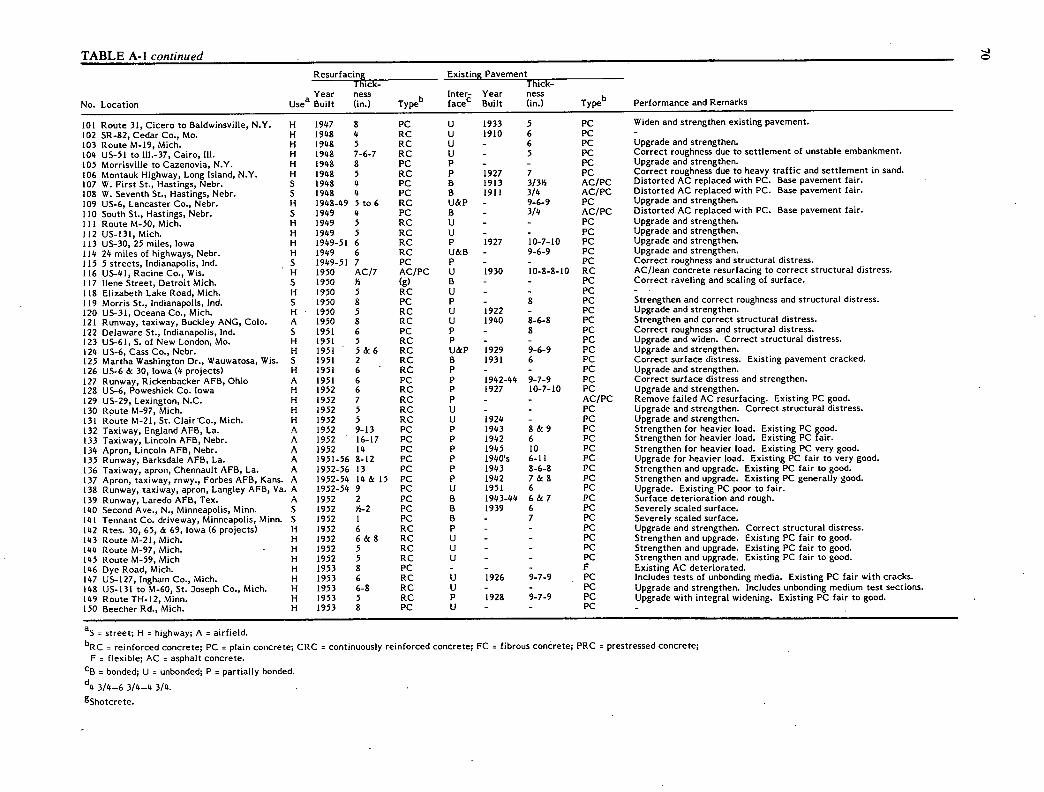
TABLE A-i continued
Resurfacing Existing Pavement Thick- Thick-
Year ness b
Inter- Year ness b No. Location Usea Built (in.) Type face' Built (in.) - Type Performance and Remarks
101 Route 31, Cicero to Baldwinsville, N.Y. H 1947 8 PC U 1933 5 PC Widen and strengthen existing pavement.
102 SR-82, Cedar Co., Mo. H 1948 4 RC U 1910 6 PC - 103 Route M-19, Mich. H 1948 5 RC U - 6 PC Upgrade and strengthen.
104 US-51 to 111.-37, Cairo, Ill. H 1948 7-6-7 RC U - 5 PC Correct roughness due to settlement of unstable embankment.
105 Morrisville to Cazenovia, N.Y. H H
1948 1948
8 5
PC RC
P P
- 1927
- 7
PC PC
Upgrade and strengthen. Correct roughness due to heavy traffic and settlement in sand. 106 Montauk Highway, Long Island, N.Y.
107 W. First St., Hastings, Nebr. S 1948 4 PC B 1913 3/3B AC/PC Distorted AC replaced with PC. Base pavement fair.
108 W. Seventh St., Hastings, Nebr. 5 1948 4 PC B 1911 3/4 AC/PC Distorted AC replaced with PC. Base pavement fair.
109 US-6, Lancaster Co., Nebr. H 1948-49 5 to 6 RC U&P - 9-6-9 PC Upgrade and strengthen.
110 South St., Hastings, Nebr. S 1949 4 PC B - 3/4 AC/PC Distorted AC replaced with PC. Base pavement fair.
111 Route M-50, Mich. H 1949 5 RC U - - PC Upgrade and strengthen.
112 US-131, Mich. H 1949 5 RC U - - PC Upgrade and strengthen.
113 US-30, 25 miles, Iowa H 1949-51 6 RC P 1927 10-7-10 PC Upgrade and strengthen.
114 24 miles of highways, Nebr. H 1949 6 RC U&B - 9-6-9 PC Upgrade and strengthen.
115 5 streets, Indianapolis, md. S 1949-51 7 PC P - - PC Correct roughness and structural distress.
116 US-41, Racine Co., Wis. H 1950 AC/7 AC/PC U 1930 10-8-8-10 RC AC/lean concrete resurfacing to correct structural distress.
117 llene Street, Detroit Mich. S 1950 B (g) B - - PC Correct raveling and scaling of surface.
118 Elizabeth Lake Road, Mich. H 1950 5 RC U - - PC - 119 Morris St., Indianapolis, lnd. 5 1950 8 PC P - 8 PC Strengthen and correct roughness and structural distress.
120 US-31, Oceana Co., Mich. H 1950 5 RC U 1922 - PC Upgrade and strengthen.
121 Runway, taxiway, Buckley ANG, Cob. A 1950 8 RC U 1940 8-6-8 PC Strengthen and correct structural distress.
122 Delaware St., Indianapolis, Ind. S 1951 6 PC P - 8 PC Correct roughness and structural distress. 123 US-61, S. of New London, Mo. H 1951 5 RC p - - PC Upgrade and widen. Correct structural distress.
124 US-6, Cass Co., Nebr. H 1951 5 & 6 RC U&P 1929 9-6-9 PC Upgrade and strengthen. 125 Martha Washington Dr., Wauwatosa, Wis. S 1951 2 RC B 1931 6 PC Correct surface distress. Existing pavement cracked. 126 US-6 & 30, Iowa (4 projects) H 1951 6 RC P - - PC Upgrade and strengthen. 127 Runway, Rickenbacker AFB, Ohio A 1951 6 PC p 1942-44 9-7-9 PC Correct surface distress and strengthen. 128 US-6, Poweshiek Co. Iowa H 1952 6 RC P 1927 10-7-10 PC Upgrade and strengthen. 129 US-29, Lexington, N.C. H 1952 7 RC P - - AC/PC Remove failed AC resurfacing. Existing PC good. 130 Route M-97, Mich. H 1952 5 RC U - - PC Upgrade and strengthen. Correct structural distress. 131 Route M-21, St. ClairCo., Mich. H 1952 5 RC U 1924 - PC Upgrade and strengthen. 132 Taxiway, England AFB, La. A 1952 9-13 PC P 1943 8 & 9 PC Strengthen for heavier load. Existing PC good. 133 Taxiway, Lincoln AFB, Nebr. A 1952 16-17 PC P 1942 6 PC Strengthen for heavier load. Existing PC fair. 134 Apron, Lincoln AFB, Nebr. A 1952 14 PC P 1945 10 PC Strengthen for heavier load. Existing PC very good. 135 Runway, Barksdale AFB, La. A 1951-56 8-12 PC p 1940's 6-11 PC Upgrade for heavier load. Existing PC fair to very good. 136 Taxiway, apron, Chennault AFB, La. A 1952-56 13 PC P 1943 8-6-8 PC Strengthen and upgrade. Existing PC fair to good. 137 Apron, taxiway, rnwy., Forbes AFB, Kans. A 1952-54 14 & 15 PC p 1942 7 & 8 PC Strengthen and upgrade. Existing PC generally good. 138 Runway, taxiway, apron, Langley AFB, Va. A 1952-54 9 PC U 1951 6 PC Upgrade. Existing PC poor to fair. 139 Runway, Laredo AFB, Tex. A 1952 2 PC B 1943-44 6 & 7 PC Surface deterioration and rough. 140 Second Ave., N., Minneapolis, Minn. S 1952 Y,-2 PC 6 1939 6 PC Severely scaled surface. 141 Tennant Co. driveway, Minneapolis, Minn. S 1952 1 PC B - 7 PC Severely scaled surface. 142 Rtes. 30, 65, & 69, Iowa (6 projects) H 1952 6 RC P - - PC Upgrade and strengthen. Correct structural distress. 143 Route M-21, Mich. H 1952 6 & 8 RC U - - PC Strengthen and upgrade. Existing PC fair to good. 144 Route M-97, Mich. H 1952 5 RC U - - PC Strengthen and upgrade. Existing PC fair to good. 145 Route M-59, Mich H 1952 5 RC U - - PC Strengthen and upgrade. Existing PC fair to good. 146 Dye Road, Mich. H 1953 8 PC - - - F Existing AC deteriorated. 147 US-127, lngham Co., Mich. H 1953 6 RC U 1926 9-7-9 PC Includes tests of unbonding media. Existing PC fair with cracks. 148 US-13l to M-60, St. 3oseph Co., Mich. H 1953 6-8 RC U - - PC Upgrade and strengthen. Includes unboriding medium test sections. 149 Route TH-12, Minn. H 1953 5 RC p 1928 9-7-9 PC Upgrade with integral widening. Existing PC fair to good. 150 Beecher Rd., Mich. H 1953 8 PC U - - PC -
a S = Street; H = highway; A = airfield.
bRC = reinforced concrete; PC = plain concrete; CRC = continuously reinforced concrete; FC = fibrous concrete; PRC = prestressed concrete; F = flexible; AC = asphalt concrete.
cB = bonded; U = unbonded; P = partially bonded.
3/4-6 3/4-4 3/4.
85hotcrete.
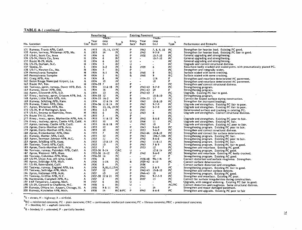
TABLE A-i continued
No. Location Usea
Resurfacing Thick-
Year ness Built (in.)
b Type
Existing
1nter face
Pavement Thick-
Year ness Built (in.)
b Type Performance and Remarks
151 Runway, Travis AFB, Calif. A 1953 10, 11, 13 PC P 1943 7,8,9, 10 PC Strengthen for heavier load. Existing PC good. 152 Apron, taxiway, Whiteman AFB, Mo. A 1953 14 PC P 1942 9-7-9 PC Strengthen for heavier load. Existing PC fair to good. 153 US-61, Scott Co., Iowa H 1954 6 RC P 1928 10-7-10 PC General upgrading and strengthening. 154 US-34, Henry Co., Iowa H 1954 6 RC P - 10-7-10 PC General upgrading and strengthening. 155 Route M-29, Mich. H 1954 6 RC U - - PC General upgrading and strengthening. 156 US-70, Durham, N.C. H 1954 5 RC U - - PC Upgrade and correct structural distress. 157 Skokie, Ill. S 1954 }G-2 PC B 1929 6 PC Resurface badly cracked and scaled pvmt. with pneumatically placed PC. 158 US-71, Newton Co., Mo. H 1954 5 RC P - - PC Strengthen and integrally widen. 159 Pennsylvania Turnpike H 1954 Y2-1 PC 6 1940 9 RC Surface scaled with some cracking. 160 Pennsylvania Turnpike H 1954 2 RC 6 1940 9 RC Surface scaled with some cracking. 161 Craig AFB, Ala. A 1954 8 PC - - IIY, F Strengthen and resurface deteriorated AC pavement. 162 Baton Rouge Municipal Airport, La. A 1954 10 PC - - 10 F Strengthen and resurface deteriorated AC pavement. 163 Route 347, Tex. H 1954-55 7 RC P - - PC Strengthen and correct structural distress. 164 Taxiway, apron, runway, Dover AFB, Del. A 1954 13 & 18 PC P 1942-43 9-7-9 PC Strengthening program. 165 Runway, Dover AFB, Del. A 1954 16 PC - 1941-43 29 F Strengthening program. 166 Apron, Ellsworth AFB, S.D. A 1954 13 PC P 1942-43 7 PC Upgrade. Existing PC fair to good. 167 Rnwy., taxiway, apron, Grissom AFB, md. A 1954-55 12 PC P - 10-8-10 PC Strengthening program. 168 Apron, Little Rock AFB, Ark. A 1954-55 114-2 PC B 1954-55 15 PC Correct for frozen surface during construction. 169 Runway, Schilling AFB, Kans. A 1954 12 & 14 PC P 1942 10-8-10 PC Strengthen for increased loadings. 170 Runway, Tinker AFB, OkIa. A 1954-56 11 & 14 PC P 1942 9-7-9 PC Upgrade and strengthen. Existing PC fair to poor. 171 Apron, Whiteman AFB, Mo. A 1954 13, 14, 19 PC P 1942 9-7-9 PC Upgrade and strengthen. Existing PC fair to poor. 172 US-34, W of Burlington, Iowa H 1955 1-3 PC B 1921 - PC Deteriorated surface and cracking in existing PC. 173 US-41, Smyrna to Nashville, Tenn. H 1955 6 PC U 1943 8 PC Upgrade and strengthen. Correct structural distress. 174 Route TH-12, Minn. H 1955 5 PC P - - PC - 75 Rnwy., txwy., apron, Blytheville AFB, Ark. A 1955 11 & 12 PC P 1942 8-6-8 PC Upgrade and strengthen. Existing PC poor to fair.
176 Rnwy., taxiway, apron, Castle AFB, Calif. A 1955 10 PC U 1946 11 PC Upgrade and strengthen. Existing PC fair. 177 Apron, taxiway, Castle AFB, Calif. A 1955 16 & 18 PC - 1942 10 F Upgrade and strengthen. Existing AC poor to fair. 178 Apron, Davis-Monthan AFB, Ariz. A 1955 12 PC P 1943 9-6-9 PC Strengthening program. Existing PC poor to fair. 179 Apron, Davis-Monthan AFB, Ariz. A 1955 10 PC U 1953 9-6-9 PC Strengthen and correct structural distress. 180 Apron, Rickenbacker AFB, Ohio A 1955 7 PC P 1942-44 10-8-10 PC Strengthen and correct for surface deterioration. 181 Runway, Mather AFB, Calif. A 1955 12 PC P 1943 1014-7-1014 PC Strengthening program. Existing PC fair. 182 Apron, Seymour-)ohnson AFB, N.C. A 1955 11 PC P 1942 8-6-8 PC Strengthening program. Existing PC poor to fair. 183 Apron, Schilling AFB, Kans. A 1955 13 & 15 PC P 1942 11-8-11 PC Strengthening program. Existing PC fair. 184 Taxiway, Travis AFB, Calif. A 1955 13 PC P 1943 . 7 & 9 PC Strengthening program. Existing PC fair to good. 185 Apron, Davis-Monthan AFB, Ariz. A 1955 7 PC P 1953 12 PC Strengthen and resurface. Existing PC good. 186 Taxiway, runway, Palmdale AFB, Calif. A 1955-56 8-14 CRC U - 12 & 14 PC Strengthening program. Existing PC good. 187 Apron, Westover AFB, Mass. A 1955-56 11-12 PC P 1942 9-6-9 PC Strengthen and resurface. Existing PC badly cracked. 188 Taxiway, Columbus AFB, Miss. A 1956-58 16 PC - - 17 F Strengthening program. Existing AC good. 189 US-99, Union Ave. off ramp, Calif. H 1956 8 RC - 1938-48 914-1114 F Correct distortion and surface roughness. Strengthen. 190 Apron, Seifridge AFB, Mich. A 1956 1-114 PC B 1929-42 6-10 PC Correct surface deterioration. 191 US-99, Bakersfield, Calif. H 1956 8 PC - 1936 - F . Correct surface distortion and strengthen. 192 Taxiway, runway, England AFB, La. A 1956 9,10,11,I3PC P 1943 8 & 9 PC Strengthening program. Existing PC fair to good. 193 Taxiway, Self ridge AFB, Mich. A 1957 12 PC P 1942-43 10-8-10 PC Strengthen and correct surface defects. 194 Apron, Holloman AFB, N.M. A 1957 13 PC P 1944-45 10 PC Strengthening program. Existing PC good. 195 Taxiway, Griffiss AFB, N.Y. A 1957-58 12 & 21 PC P 1941 9-7-7-9 PC Strengthen and resurface. Existing PC poor. 196 Hardstands, Campbell AFB, Ky. A 1957 2 PC 6 1957 15 PC Correct for surface irregularities during construction.. 197 1-69 Temporary, Lansing, Mich. H 1957 6 RC U - - PC Upgrade, with integral widening. Existing PC fair to good. 198 US-29, Concord to Charlotte, N.C. H 1958 6 RC Ii - - AC/PC Correct distortion and roughness. Some structural distress. 199 Runway, O'Hare tnt. Airport, Chicago, Ill. A 1958 9 & 11 PC - - 24 F Strengthen and repair damaged pavement. 200 Runway, Kincheloe AFB, Mich. A 1958 14 RC & PC P 1942 8-6-8 PC Strengthen and upgrade. Existing PC poor to fair
as = street; H = highway; A = airfield. bRC r reinforced concrete; PC r plain concrete; CRC = continuously reinforced concrete; FC = fibrous concrete; PRC = prestressed concrete;
F = flexible; AC = asphalt concrete.
cB = bonded; U = unbonded; P = partially bonded.

TABLE A-i continued
Resurfacing Existing Pavement Thick- Thick-
Year ness b Inter- Year ness b
No. Location Usea Built (in.) Type face' Built (in.) Type Performance and Remarks
201 Runway, Kincheloe AFB, Mich. A 1958 12 RC - 1942 9 F Strengthen and upgrade. Existing AC fair. 202 Runway, Kincheloe AFB, Mich. A 1958 12 PC P 1957 9 & 10 PC Strengthen and resurface. Existing PC fair to good. 203 Taxiway, Glasgow AFB, Mich. A 1958-59 15 RC - - 55 F Strengthening program. Existing AC fair. 204 Runway, Self ridge AFB, Mich. A 1958-59 9 PC P 1942-43 12-10-12 PC Upgrade and correct for surface distress. 205 Runway, Self ridge AFB, Mich. A 1958-59 13 PC - 1951 34 F Strengthening program. Existing AC fair. 206 Taxiway, K.I. Sawyer AFB, Mich. A 1958-59 8 & 16 PC P 1955-57 16 PC Upgrade and resurface. 207 US-99, Kern Co., Calif. H 1959 8 PC U - - AC/PC Upgrade and correct for surface distortion and roughness. 208 US-99, Madera Co. Calif. H 1959 9 PC U 1929 7 & 9 AC/PC Upgrade and correct for surface distortion and roughness.
209 1-5, near Gorman, Calif. H 1959 8 PC - 1949 - F Upgrade and correct for surface distortion and roughness. 210 Runway, Standiford Field, Louisville, Ky. A 1959 4 PC B 1944 6/9-6-6-9 PC/PC Strengthen. Correct surface distress and improve grade.
211 1-35, Falls & McLennan Cos., Tex. H 1959 7 CRC U 1934 314/9-6-9 AC/PC Strengthen and improve rideability. 212 Apron, San Antonio lnt. Airport, Tex. A 1959 4 PRC U - 6 PC Experimental strengthening. Existing PC fair to good. 213 Apron, Grissom AFB, md. A 1959 3 PC 6 1942-43 10-8-10 PC Correct for surface irregularities.
214 Apron, Self ridge AFB, Mich. A 1959 6 RC P 1942-43 12-10-12 PC Strengthen and correct surface distress.
215 Woodbury Co., Iowa H 1960 6 PC - - - F Strengthen and improve rideability.
216 Runway, Randolph AFB, Tex. A 1960 216 PC B 1944 8 PC Strengthen and correct surface distress.
217 Runway, Los Angeles Int. Airport, Calif. A 1960 1014& 15 PC - - - F Upgrade and correct surface distortion and cracking.
218 Apron, Glenview NAS (Phase I), Ill. A 1961 5 PC B 194 1-42 6 & 7 PC Strengthen and correct surface distress.
219 Runway, Andrews AFB, Md. A 1961 2-6 PC B 1941 12-9-12 PC Correct roughness.
220 Taxiway, Langley AFB, Va. A 1961 16 PC P 1944 10 PC Strengthening program. Existing PC good.
221 Runway, apron, Otis AFB, Mass. A 196 1-62 7 PC B&P 1955 10 PC Strengthen and correct surface irregularities.
222 Kellogg Field, Battle Creek, Mich. A 1962 2 PC 6 - 8 PC Correct surface distress.
223 Ashworth Rd., W. Des Moines, Iowa H 1963 5 PC P - 10-7-10 PC Correct surface distress and structural cracking.
224 Apron, Glenview NAS (Phase II), Ill. A 1963 5 PC B 194 1-42 9 PC Strengthen and correct surface distress.
225 Apron, Detroit Municipal Airport, Mich. A 1963 2 PC B 1935-41 9 PC Correct surface distress.
226 Runway, Self ridge AFB, Mich. A 1963 3 PC B 1954 12 PC Correct surface distress.
227 US-99, Kern Co., Calif. H 1964 7 PC - 1922-48 914-13 F Upgrade and improve serviceability.
228 US-6-34, Red Willow Co., Nebr. H 1964 5 RC U - 8 PC Upgrade and strengthen.
229 1-35, Guadalupe Co., Tex. H 1965 6 CRC U 1934 214/9-6-9 AC/PC Upgrade and improve serviceability.
230 1-35, 3ohnson Co., Tex. H 1965 6 CRC U 1936 3/9-6-9 AC/PC Upgrade and improve serviceability.
231 Runway, Grissom AFB, md. A 1965 2 PC B 1954-55 14 PC Correct surface distress.
232 1-5, Los Angeles Co., Calif. H 1966 8 PC U - - PC - 233 US-91, Orange Co., Calif. H 1966 8 PC - - - F Upgrade and improve serviceability.
234 US-101, Los Angeles Co., Calif. II 1966 7 PC - - - F Upgrade and improve serviceability.
235 1-70, Bond Co., Ill. H 1967 7 CRC U - 10 PC Upgrade and improve serviceability.
236 1-70, Wof Pocahontas, Ill. H 1967 6, 79 8 CRC U 1939 10-8-10 AC/PC Experimental sections. Improve rideability.
237 Midway Airport, Chicago, Ill. A 1967 8 CRC - - - F Strengthen and correct distorted existing pavement. 238 Apron, Patuxent NAS, Md. A 1967 5 CRC P - 9 RC Strengthen and resurface structurally distressed pavement.
239 Apron, Rickenbacker AFB, Ohio A 1967-68 2 PC B 1954 12 PC Correct surface distress.
240 US-99, N. of Bakersfield, Calif. H 1968 8 PC U 1914 12/4 AC/PC Improve serviceability due to distorted AC.
241 1-8, E of San Diego, Calif. H 1968-69 6 PC U 1951 - PC Upgrade to Interstate standards. 242 1-80, W of Sacramento, Calif. H 1968 8 PC U&P - - PC Upgrade. Experimental sections of unboriding media.
243 1-5, Project City, Calif. H 1968 6 PC - 1950-54 8 & 12 AC/CTB Strengthen and improve rideabilty.
244 1-55, near Springfield, Ill. H 1968 8 CRC U - 10 RC Upgrade to Interstate standards.
245 1-69, N of Indianapolis, Ind. I-I 1970 6 CRC P 1955 9 RC Upgrade existing RC to Interstate standards.
246 Route 163, San Diego Co., Calif. H 1970 6 & 8 PC U - - PC - 247 1-5, S. of Portland, Ore. (4 projects) H 1969-75 7 & 9 CRC - 1950 - F Upgrade existing F to Interstate standards.
248 Woodbury Co., Iowa H 1971 6 PC - - - F Strengthen and improve rideability.
249 1-75, N of Macon, Ga. H 1971 7 & 8 CRC P 1954 9-8-10 PC Upgrade existing PC to Interstate standards.
250 Storm Lake Airport, Iowa A 1971 5. PC - - - F Strengthen and correct surface distortion.
a S = street; H = highway; A = airfield.
bRC = reinforced concrete; PC = plain concrete; CRC = continuously reinforced concrete; FC = fibrous concrete; PRC = prestressed concrete; F = flexible; AC = asphalt concrete.
cB = bonded; U = unbonded; P = partially bonded.

TABLE A-i continued
Resurfacing Existing Pavement Thick- Thick-
Year ness b
Inter- Year ness b No. Location Usea Built (in.) Type face' Built (in.) Type Performance and Remarks
251 1-69, N of Indianapolis, md. H 1971 6 CRC U 1955 9 RC Upgrade existing pavement to Interstate standards. 252 1-20, Vicksburg, Miss. H 1971 6 CRC U - 9 RC Upgrade existing pavement to Interstate standards. 253 1-80, Near Ladd, Ore. H 1971 7 & 9 CRC - - - F Upgrade existing pavement to Interstate standards. 254 1-40, Potter Co., Tex. H 1971 8 CRC - - 12-16 F Upgrade existing pavement to Interstate standards. 255 Manteno Road, Kankakee Co., Ill. H 1971 6 PC P - 6 & 7 PC&F ACPA pave-in demonstration. Existing PC cracked. Existing F distorted. 256 Exp. overlay, WES, Vicksburg, Miss. TP 1971 4 FC P 1970 10 PC Test resurfacing. Existing PC trafficked and cracked. 257 1-70W of Baltimore, Md. (3 projects) H 197142 6 CRC U - 9 PC&RC Upgrade existing pavement to Interstate standards. 258 Apron, Patuxent NAS, Md. A 1971 5 CRC P - 9 RC Strengthen and resurface cracked pavement. 259 US-99, Tulare Co., Calif. H 1971 7 PC U 1915 - AC/PC Upgrade and restore rideability. 260 Apron, Glenview NAS, Ill. (Phase 11) A 1972 5 & 6 CRC P - 6 & 7 PC Strengthen and resurface cracked pavement. 261 1-205, E of Portland, Ore. H 1972 7-9 CRC - - - - - 262 Taxiway, Tampa mt. Airport, Fla. A 1972 4 & 6 FC P - 12 PC Test resurfacings. Existing PC cracked but in good condition. 263 Danbury St., Cedar Rapids, Iowa S 1972 3 FC P - 7 RC Resurface because of surface distress. 264 Fifth Avenue., S.E., Cedar Rapids, Iowa S 1972 214 FC - - - AC/Brick Resurface distorted surface. 265 1-55, W. Memphis, Ark. H 1972 6 CRC U 1951 9 RC Upgrade existing pavement to Interstate standards. 266 Taxiway, Cedar Rapids Airport, Iowa A 1972 3 FC P - - PC Resurface distressed surface. 267 1-29, Grand Forks, N.D. H 1972 6 CRC U 1958 8 PC Upgrade existing pavement to Interstate standards. 268 M-102, 8 Mile Road, Detroit, Mich. H 1972 3 FC P - - PC Experimental resurfacing of surface distressed pavement. 269 1-40, W of Bushland, Tex. H 1972 8 CRC - 1953 16+ F Upgrade existing pavement to Interstate standards. 270 1-83, S of Pa. border, Md. H 1973 6 CRC U - 9 RC Upgrade existing pavement to Interstate standards. 271 Route E-53, Greene Co., Iowa H 1973 3 & 4 CRC U 1921-22 814 RC Test resurfacings with integral widenings. Existing pvmt. cracked. 272 Route E-53, Greene Co., Iowa H 1973 2 & 3 FC B,U,P 1921-22 814 RC Test resurfacings with integral widenings. Existing Pvmt. cracked. 273 Route E-53, Greene Co., Iowa H 1973 4 & 5 RC P 1921-22 814 RC Test resurfacings with integral widenings. Existing pvmt. cracked. 274 Route E-53, Greene Co., Iowa H 1973 5 PC P 1921-22 814 RC Test resurfacings with integral widenings. Existing Pvmt. cracked. 275 1-205, E of Portland, Ore. H 1973 7 & 9 CRC - 1959 - F Upgrade existing pavement to Interstate standards. 276 1-75, Forsyth to Macon, Ga. H 1973 8 CRC P - 8, 9, 10 PC Upgrade existing pavement to Interstate standards. 277 1-75, Forsyth to Macon, Ga. H 1973 7 CRC P - 10 PC Upgrade existing pavement to Interstate standards. 278 1-29, Walsh Co., N.D. H 1973 6 CRC - - - F Upgrade existing pavement to Interstate standards. 279 1-30, Little Rock, Ark. H 1973 6 CRC - - - F Upgrade existing pavement to Interstate standards. 280 US-16, Hartl and- Pewaukee, Wis. H 1973 7 CRC U 1950's 9 PC Upgrade and strengthen. 281 1-10, Beaumont, Tex. H 1973 3-314 FC P - 8 CRC Experimental resurfacing of distressed CRC. 282 1-5, Siskiyou Co., Calif. H 1973 814 PC - 1971 514 F Upgrade existing pavement to Interstate standards. 283 Rnwy., 3FK mt. Airport, New York, N.Y. A 1974 5 FC U - - AC/PC Remove distressed AC and resurface with FC. 284 Tank Apron, Ft. Hood, Tex. S 1974 4 FC - - 17-19 F Resurface distressed AC for tank parking. 285 Snelling Ave., St. Paul, Minn. S 1974 3 PC B - - PC Test resurfacing of surface distressed area. 286 Snelling Ave., St. Paul, Minn. S 1974 2 & 3 FC B&P - - PC Test with glass and steel fibers, epoxy and sand-cement bond. 287 Clinton Co., Iowa H 1974 6 PC - - - F Strengthen and improve rideability. 288 1-29, Walsh Co., N.D. H 1974 6 CRC U - 8 PC Upgrade existing pavement to Interstate standards. 289 Plank Rd., Peru, Ill. H 1974 5 PC - - 8 F Strengthen and improve rideability. 290 Taxiway, Moody AFB, Ga. A 1974 6 CRC B&P - - F Strengthen and resurface deteriorated pavement. 291 1-85, Gwinnett Co., Ga. H 1975 3, 414, 6 CRC U 1960 9 PC Thickness test sections of distressed pavement. 292 1-85, Gwinnett Co., Ga. H 1975 6 PC U 1960 9 PC Existing pavement distressed. 293 1-80, Ore. H 1975 7 & 9 CRC - - - F Upgrade existing pavement to Interstate standards. 294 Apron, Portland mt. Airport, Ore. A 1975-76 3 FC U - 414 PC Replace rutted asphaltic concrete in parking areas. 295 1-610, Houston, Tex. H 1975 8 CRC - - - PC Upgrade existing pavement to Interstate standards. 296 Apron, Reno Municipal Airport, Nev. A 1975 4 FC B 1958-59 11 PC Strengthen and resurface. 297 1-90, Near Erie, Pa. H 1975-77 7 CRC U 1957-61 10 RC Upgrade existing pavement to Interstate standards. 298 1-86, Near Mass, border, Conn. H 1975-76 6 CRC U 1948-54 8 RC Upgrade existing pavement to Interstate standards. 299 1-5, Ore. H 1975 - CRC - - - F Upgrade existing pavement to Interstate standards. 300 1-45, Houston to Galveston, Tex. H 1976 6 CRC U - - PC Upgrade existing pavement to Interstate standards.
aS = street; H = highway; A = airfield; TP = test project.
bRC = reinforced concrete; PC = plain concrete; CRC = continuously reinforced concrete; FC = fibrous concrete; PRC = prestressed concrete; F = flexible; AC = asphalt concrete.
c6 = bonded; U = unbonded; P = partially bonded.

TABLE A-i continued Resurfacing Existing Pavement
Thick- Thick- Year ness b
Inter- Year ness b No. Location Usea Built (in.) Type facec Built (in.) Type Performance and Remarks
301 Columbus St., Anderson, md. S 1976 3 & 4 PC & RC U&P 1944 8 RC Test resurfacings of distressed street. 302 US-20, Waterloo, Iowa H 1976 2 PC B 1958 10 PC Alleviate joint and surface distress, some cracking. 303 Prospect Blvd., Waterloo, Iowa S 1976 1-2 PC B 1940's 6 RC Surface and joint distress, some cracking. 304 Hammond Ave., Waterloo, Iowa S 1976 1-2 PC B 1940's 6 RC Surface and joint distress, some cracking.
305 US-84, Brookhaven, Miss. H 1976 6 PRC U 1976 4 AC/4 Granular New PRC resurfacing of foundation simulating existing F Pvmt.
306 Apron, McCarran Field, Las Vegas, Nev. A 1976 6 FC - - 18 F Upgrade deteriorated pavement.
307 Newark mt. Airport, N.J. A 1976 4 FC - - - F Remove existing distorted AC and resurface with FC
308 1-84, Snowville, Utah H 1976 9 PC - 1966 - F Strengthen and improve rideability.
309 Clinton Co., Iowa H 1977 6 PC - - - F Strengthen and improve rideability.
310 Route 163, San Diego, Calif. H 1977 9 PC - - - F Improve serviceability.
311 Cedar Co., Iowa H 1977 6 PC - 1955 - F Strengthen and improve rideability.
312 Dallas Co., Iowa H 1977 5 PC - 1955 11 F Strengthen and improve rideability.
313 Washington Co., Iowa H 1977 5 PC - 1958 121 F Strengthen and improve rideability.
314 Boone Co., Iowa H 1977 5 PC - 1957 II F Strengthen and improve rideability.
315 Apron, La Guardia lnt. Airport, N.Y. A 1977 6 FC - - - F Remove distorted AC and resurface with FC
316 Apron, Norfolk NAS, Va. A 1977-79 5 FC U - 114-3/8 AC/PC Existing AC distorted and PC badly cracked.
317 C-17, Clayton Co., Iowa H 1977 3, 4, 5 RC B 1968 6 PC Strengthen existing pavement for heavier traffic.
318 C-17, Clayton Co., Iowa H 1977 2 PC B '1968 6 PC Strengthen existing pavement for heavier traffic.
319 TH-71, Kandiyohi & Renville Cos., Minn. H 1977 514 PC U - 9-7-9 PC - 320 Aprons, Patuxent NAS, Md. (7 projects) A 1977-8 1 6 CRC U - 8 PC Strengthen existing distressed pavement.
321 Grundy Co., Iowa H 1978 5 PC - - - F Strengthen and improve rideability.
322 US-20, Sioux City, Iowa H 1978 3 PC B - 9 PC Correct surface distress. Existing pavement cracked.
323 1-35W, Blaine, Minn. H 1978 2-3 PC B 1969 8 CRC Correct surface distress. 324 Runway, Willard Airport, Champaign, Ill. A 1978 8 PC B&P 1944 8 PC Strengthen existing pavement.
325 US-24, Shawnee Co., Kans. H 1978 6 PC U 1956 - RC Strengthen and improve rideability.
326 1-86, NE of Hartford, Conn. H 1978-79 6 CRC U - 9 RC . Upgrade existing pavement to Interstate standard.
327 1-80, Wyo. line to Wahsatch, Utah H 1979 10 PC - - - F Strengthen and improve serviceability.
328 Route 12, N of Utica, N.Y. H 1979 2 PC B 1970 9 PC Correct surface distress. 329 1-80, Pottawattamie Co., Iowa H 1979 3 PC B 1966 8 & 10 CRC & RC Correct surface, joint and crack distress.
330 Hines Dr., Wayne Co., Mich. S 1979 5 PC U 1939 9 AC/PC Replace distorted AC. Existing PC cracked.
331 1-80, W of Des Moines, Iowa H 1979 10 PC - 1959-72 37 F Inlay to correct AC distortion and cracking.
332 Public Square, Indianola, Iowa S 1979 2 PC B 1949 6 RC Correct surface distress.
333 Centerville Airport, Iowa A 1979 5 PC - - - F Strengthen and restore serviceability.
334 Apron, McCarran FId., Las Vegas, Nev. A 1979 7 FC - - 14 F Strengthen and correct distortion and cracking.
335 1-80, Wahsatch to Castle Rock, Utah H 1980 10 PC - - - F Strengthen and restore serviceability.
336 1-84, SW of Boise, Ida. H 1980 7 PC - - 14 F Inlay to replace distorted and cracked AC.
337 New Utrecht Ave., N.Y. City, N.Y. S 1980 2 PC B - - PC Correct surface distress. 338 Vine Street, W. Des Moines, Iowa S 1980 2 PC B 1950-60 5-6 PC Correct surface distress and structural deficiencies. 339 Runway, O'Hare tnt. Airport, Chicago, Ill. A 1980 8 & 9 PRC U - - CRC Strengthen and correct structural deficiencies.
340 1-94, \Varrens & Millston, Wis. H 1980-81 8 CRC U 1970 - RC Strengthen and restore serviceability.
341 1-55, W of W. Memphis, Ark. H 1980 6 CRC - - - PC Strengthen and restore serviceability.
342 Dallas Co., Iowa H 1980 4 PC - - - F Strengthen and correct surface distortion and cracking.
343 Clayton Co., Iowa H 1980 6 PC - - - F Strengthen and correct surface distortion and cracking.
344 Apron, Fallon NAS, Nev. A 1980 5 FC U - - PC Strengthen and correct surface distress.
345 Rnwy., JFK tnt. Airport, N.Y. City, N.Y. A 1980 4-7 FC U - - AC/PC Remove distorted AC and replace with FC.
346 Runway, Newark tnt. Airport, N.J. A 1980 3 FC B - - FC Resurface and raise grade of runway ends.
347 Apron, Norfolk NAS (3 projects), Va. A 1980-81 5 FC U - 114-3/8 AC/PC Strengthen and correct for surface distress.
348 1-43, Green Bay to Sheboygan, Wis. H 1981 6 CRC U - - PC - 349 1-45, La Marque, Galveston Co., Tex. H 1981 6 CRC U 1949-51 9 & 10 PC Upgrade existing pavement to Interstate standard.
350 US-61, Port Hudson, La. H 0 1981 3-4% PC B 1960 - PC Correct surface distress and improve rideability.
as = street; H = highway; A = airfield. bRC = reinforced concrete; PC = plain concrete; CRC = continuously reinforced concrete; FC = fibrous concrete; PRC = prestressed concrete;
F = flexible; AC = asphalt concrete.
cB = bonded; U = unbonded; P = partially bonded.

TABLE A-i continued
No. Location Usea
Resurfacing Thick-
Year ness Built (in.)
b Type
Existing Pavement Thick-
1ntei Year ness face Built (in.)
b Type Performance and Remarks
351 1-80, W of Salt Lake City, Utah H 1981 11 PC - - - F Strengthen and restore serviceability. 352 Penn-Lincoln Pkwy., Pittsburgh, Pa. H 198 1-82 8 RC U - 10 RC Strengthen and restore serviceability. 353 1-59, Ellisville to Moselle, Miss. H 1981 6 CRC U - 8 CRC Strengthen and restore serviceability. 354 1-80, Adair Co., Iowa H 1981 10 PC - - F Inlay of traffic lane to replace distorted and cracked AC. 355 Adair Co., Iowa H 1981 6 PC U - - PC Correct surface distress and structural cracking. 356 Luther, Boone Co., Iowa H 1981 6 PC - - - F Strengthen and improve rideability. 357 Greene County Line, Greene Co., Iowa H 1981 6 PC - - - F Strengthen and improve rideability. 358 R-18, Boone Co., Iowa H 1981 6 PC - - - F Strengthen and improve rideability. 359 Great River Road, Clayton Co., Iowa H 1981 3 PC B 1968 6 PC Strengthen existing pavement for heavier loadings. 360 C-38, Cherokee Co., Iowa H 1981 6 PC - - - F Strengthen and improve rideability. 361 F-31, Dallas Co., Iowa H 1981 5 PC - - - F Strengthen and improve rideability. 362 X-23, Henry Co., Iowa H 1981 5 PC - - - F Strengthen and improve rideability. 363 3-20, Jct. 218, Henry Co., Iowa H 1981 7 PC - - - F Strengthen and improve rideability. 364 G-61, US-169, Madison Co., Iowa H 1981 5 PC U - - PC Correct surface distress and structural cracking. 365 F-41, Scott Co., Iowa H 1981 6 PC - - - F Strengthen and improve rideability. 366 IA-92 to Wel!man, Washington Co., Iowa H 1981 8 PC - - - F Strengthen and improve rideability. 367 IA-92 to ict. 114, Washington Co., Iowa H 1981 7 PC - - - F Strengthen and improve rideability. 368 E-W Toliway, Chicago, Ill. 369 1-80, W of Truckee, Calif.
H H
1981 1981
8 2.5,3,3.6
PC PC
U - 3-4/10 B - 8
AC/PC Replace AC resurfacing to strengthen and improve serviceability.
370 1-77, N of Princeton, W. Va. H 1981 8 RC U&P 1978-79 10 PC RC
Correct surface distress. Strengthen and correct for structural distress.
371 1-81, N of Syracuse, N.Y. H 1981 3 PC B - 9 PC Correct surface distress. 372 Apron, Salt Lake City Airport, Utah 373 Apron, Salt Lake City Airport, Utah
A A
1981 1981
7 8
FC FC
U - 12 AC/PC Apron reconstruction - strengthen and correct structural distress.
374 Apron, Fallon NAS, Nev. A 1981 5 FC - - - U - -
F PC
Apron reconstruction - strengthen and correct structural distress. Strengthen and correct surface distress.
375 Apron, Stapleton Airport, Denver, Cob. A 1981 4-7 FC - - - - -
as = Street; H = highway; A = airfield.
bRc = reinforced concrete; PC = plain concrete; CRC = continuously reinforced concrete; FC = fibrous concrete; PRC = prestressed concrete F = flexible; AC = asphalt concrete.
c13 = bonded; U = unbonded; P = partially bonded.
-4 .1

76
TABLE A-2 NUMBER OF CONCRETE RESURFACING PROJECTS BY RESURFACING, INTERFACE, AND EXISTING PAVE-MENT TYPES AND USE
Existing Use and R.esurfacin Typea Pave,ent Highways Streets Airfields
Interface Type PC RC CRC PC PRC PC RC CRC FC PRC PC RC CRC FC PRC
Bonded PC 14 3 - - - 12d - - 1e RC 3 - - 1 - 2 - - - - - - - - - CRC 2 - - - - - - - - - - - - - - FC - - - - - - - - - - - - - 1 -
Partially PC 13 36 2 1 - 10 11 - I - 36 2 1 4e - Bonded RC 1 2 2 1 - 2 1 - I - - - 2 - -
CRC - - - I - - - - - - - - - - -
Unbonded PC 21 40 14 - - 1 3 - - - 10 1 2 7 1 RC 2 4 10 1 - 1 1 - - - 1 - - - - CRC - - I - - -
Other Flexible 38 1 9 - 1 - 1 - 2g - 13 2 2 5 - Brick - 3 - - - 1 1 - - - - - - - - Base 3 - - - - 3 - - - - - - - - -
aPC - plain concrete. RC - conventionally reinforced concrete. CRC - continuously reinforced concrete. FC - fibrous concrete. PRC'- prestressed concrete. Base - Existing AC, brick, or wood block surfacing removed and concrete resurfacing placed on base.
bincludes Interstate, state, and county highways.
cincludes runways, taxiways, and aprons.
dlncludes one gunite resurfacing.
elncludes experimental test sections.
lncludes resurfacing of Packard test track. Include5 resurfacing of tank parking area.

TABLEA-3 BONDED CONCRETE RESURFACING PROJECTS
Thick- 3oint Spacing (ft) ness
b Transverse c No. Usea (in.) Type Reinforcement Long. Contr. Exp. Bonding Procedure Condition
'S 1 - 2 RC Mesh (light) - - - Surface swept & washed; dry cement sprinkled on wet surface Good after 40 yr 2 S 2 - 3 RC Mesh - 28 lb None None 40 Surface broomed, scrubbed, and grout applied Fair after 40 yr 4 S 314 RC Triangular wire mesh Coincide with base Surface broomed, scrubbed; dry cement sprinkled on wet surface - 8 S 14 - 14 Gunite None No joints used Surface broomed Gunite peeled off
10 5 4 RC Mesh - 30 lb None None 35 Surface scrubbed and cement grout used Satisfactory after 3 yr 37A H 214 - 3 RC Mesh - 42 lb - - - AC removed, surface swept, stiff cement grout applied Good after 1 yr 376 H 214 - 3 PC None - - - AC removed, surface swept, stiff cement grout applied Good after 1 yr 59 H 2 PC None Coincide with base - Unknown 64 I-I 2 - 9 PC None Coincide with base Surface scarified (stardrills), air blown, swept, wetted, W-C grout Poor after 15 yr 65 H 2 PC None - - - Surface swept, vacuum concrete resurfacing Excellent after 1 yr 74 5 4 PC None Coincide with base Surface scarified (stardrills), air blown, water washed, S-C grout Good after 11 yr 75 H 114 PC None Coincide with base Surface scarified (stardrills), air blown, water washed, S-C grout Poor after 11 yr 93 H 454 PC None t 25 100- 200 AC removed, roughened, swept, wetted; dry cement to form 1:1.75 grout -
107 5 4 PC None 10 10 - AC removed, swept, cement slurry applied Good after 8 yr 108 5 4 PC None 13 10 - AC removed, swept, cement slurry applied Good after 5 yr 110 5 4 PC None 13 12 - AC removed, swept, cement slurry applied Good after 4 yr 117 5 14 Shotcrete None No joints used Surface broomed, swept, and air blown Poor after 4 yr 125 5 2 RC Mesh - - - Surface scarified (Tennant), water flushed, 1:1 S-C grout used Fair after 4 yr 139 A 2 PC None Coincide with base Surface swept, acid etched, water flushed, 1:1 S-C grout used - 140 5 14- 2 PC None Coincide with base Surface scarified (Tennant), air blown, water flushed, 1:1 S-C grout Good after 3 yr 141 5 1 PC None Coincide with base Surface scarified (Tennant), broomed, wetted, W-C grout used Poor after 1 yr 157 5 14 - 54 Pneu. PC None Coincide with base Edges scarified (Tennant), acid etched, flushed, airblown, spray-creted Excellent after 2 yr 159 H 34 - 2 PC None Coincide with base Surface scarified (Tennant), acid etched, flushed, pneu. applied S-C grout Good after 10 yr 160 H 2 RC Mesh Coincide with base Surface scarified (Tennant), acid etched, flushed, pneu. applied S-C grout Good after 10 yr 168 A 114 - 2 PC None Coincide with base Surface scarified (Tennant), acid etched, flushed, 1:1 S-C grout used Excellent after 26 yr 172 H 1, 2, 3 RC Mesh Coincide with base Detergent scrub, acid etched, flushed, 1:1 S-C grout pneu. applied Poor; early bond loss 190 A I PC None Coincide with base Scarified (Tennant) or detergent scrubbed, acid etched, flushed, 1:1 S-C grout Fair after 8 yr 196 A 2 PC None Coincide with base Surface scarified (Tennant), acid etched, flushed, 1:1 S-C grout Excellent after 24 yr 210 A 4 PC None Coincide with base Surface scarified (Tennant), acid etched, flushed, 1:1 S-C grout Excellent after 5 yr 213 A 3 PC None Coincide with base Surface scarified (Tennant), acid etched, flushed, 1:1 S-C grout Very good after 21 yr 216 A 214 PC None Coincide with base Surface sandblasted, acid etched, water flushed, 1:1 S-C grout Fair after 21 yr 218 A 5 PC None Coincide with base Surface scarified (Tennant), acid etched, water flushed, 1:1 S-C grout Excellent after 3 yr 219 A 2 - 6 PC None Coincide with base Surface sandblasted, acid etched, water flushed, 1:1 S-C grout Excellent after 3 yr 221 A 7 PC None Coincide with base Surface sandblasted, acid etched, water flushed, 1:1 S-C grout Very good after 19 yr 222 A 2 PC None Coincide with base Surface scarified (Tennant), acid etched, water flushed, 1:1 S-C grout Excellent after 2 yr (d) Exp. II PC None Coincide with base Surface broomed, acid etched, water flushed, 1:1 S-C grout Bond excellent during test
as = street; H = highway; A = airfield
bRC = reinforced concrete; PC = plain concrete; CRC r continuously reinforced concrete; FC = fibrous concrete
cW_C = water-cement; S-C = sand-cement
dSharonville, Ohio

TART F A-i rnnlinupl!
00
Thick- Joint Spacing (ft) ness b
Transverse No. Usea (in.) Type Reinforcement Long. Contr. Exp. Bonding ProcedureC Condition -
224 A 5 -- PC None Coincide with base Surface scarified (Tennant), acid etched, water flushed, 1:1 S-C grout Excellent after 1 yr
225 A 2 PC None Coincide with base Surface scarified (Tennant), acid etched, water flushed, 1:1 S-C grout Excellent after 2 yr
226 A 3 PC None Coincide with base Scarified (Tennant) or detergent scrub, acid etched, flushed, 1:1 S-C grout Very good after 17 yr
231 A 2 PC None Coincide with base Scarified (Tennant), swept, acid etched, water flushed, 1:1 S-C grout Good after 15 yr
239 A 2 PC None Coincide with base Scarified (Tennant) or detergent scrub, acid etched, flushed, 1:1 S-C grout Good after 14 yr
271 H 3, 4 CRC L-0.45%; T-0.05% it None None Broom swept, sprinkled cement on wet surface, broomed to form grout Fair after 5 yr; bond loss
272 H 2, 3 FC 60, 100 & 160 Ib/cy steel fibers it 40 None Broom swept, sprinkled cement on wet surface, broomed to form grout Fair after 5 yr; bond loss
285 S 2 PC None Coincide with base Surface sandblasted, broomed, epoxy bond - 286A S 3 FC 160 Ib/cy steel fibers 4 15 - 39 None Surface sandblasted, broomed, epoxy bond
286B S 2 FC 160 Ib/cy steel fibers; 50 glass 4 15 - 39 None Surface broomed, water flushed, W-C slurry - 296 A 4 FC 200 Ib/cy steel fibers 1214 & 20 20 & 25 None Surface sandblasted, broomed, flushed, 1:1 S-C grout Good after 6 yr
302 H 2 PC None It& none 20 & none None Surface cold milled, sandblasted, air blasted, 1:1 S-C grout Excellent after 5 yr
303 S I - 2 PC None None None 100-600 Surface cold milled, sandblasted, air blasted, 1:1 S-C grout Fair after 5 yr
304 5 1 - 2 PC None None None 300 Surface cold milled, sandblasted, air blasted, 1:1 S-C grout Fair after 5 yr
317A H 214 & 3 PC & RC No. 4 bars 12" c-c trans. t & none Match exist. None Surface sandblasted, air blasted, W-C grout used These Sections are fair to
317B H 4, 5 RC No. 4 bars 12" c-c trans. . It & none Match exist. None Surface cold milled, vacuumed or air blasted, 1:1 S-C grout very good after 4 yr. Some
318A H 2 PC None f & none Match exist. None Surface cold milled, sandblasted, air blasted, 1:1 S-C grout
Nbetter
debonding and reflection
318B H 2, 3, 4, 5 PC None it & none Match exist. None Surface cold milled, vacuumed or air blasted, 1:1 S-C grout cracking. Milled and/or
318C H 2, 3,4 PC None t & none Match exist. None Surface sandblasted, air blasted, 1:1 S-C grout sandblasted generally
318D H 2,3 PC None 4 & none Match exist. None Surface water blasted, 1:1 S-C grout than water blasted.
322 H 3 PC None Coincide with base Surface cold milled, sandblasted, swept, air blasted, 1:1 S-C grout Very good after 2 yr
323 H 2- 3 PC None it 15 None Surface cold milled, sandblasted, air blasted, 1:1 S-C grout -
324 A 8 PC None Coincide with base Surface cold milled, power broomed, waterblasted, 1:1 S-C grout Excellent after 3 yr
328 H 2 PC None Coincide with base Surface cold milled, sandblasted, air blasted, 1:1 S-C grout -
329 -4 3 PC None 4 20 - 80 for RC 1000 Surface cold milled, sandblasted, air blasted, W-C grout Excellent after 2 yr
332 S 2 PC None Coincide with base Surface sandblasted or scarified, air blasted, 1:1 S-C grout Excellent after 2 yr
337 5 2 PC None Coincide with base AC removed, cold milled, swept, air blasted, 1:1 S-C grout Excellent after 1 yr
338 S 2 PC None Coincide with base Cold milled AC of, f, vacuumed, water-sand blasted, air blasted, 1:1 S-C grout Excellent after 1 yr
346 A 3 FC 85 lb/cy steel fibers 25 100 None Swept, air blasted, epoxy bonded - 350 H 3- 4% PC None It 20 None Surface shotblasted, vacuumed, air blasted, 1:1 W-C grout sprayed Excellent after 6 months
359 H 3 PC None 4 20 None Surface cold milled, air blasted, 1:1 S-C grout - Excellent after 6 months
369 H 2.5, 3, 3.6 PC None Coincide with base Surface sandblasted, air blasted, W-C grout sprayed Bond failed; AC overlay
371 H 3 PC None Coincide with base Surface cold milled, sandblasted, vacuumed, 1:1 S-C grout Excellent after 6 months
a5 = street; H = highway; A = airfield
bRC m reinforced concrete; PC = plain concrete; CRC = continuously reinforced concrete; FC = fibrous concrete
cW_C = water-cement; S-C = sand-cement

TABLE A-4 PARTIALLY BONDED CONCRETE RESURFACING PROJECTS
Thick-
a ness b 3oint Spacing (ft)
No. Use (in.) Type Reinforcement Long. Trans. Exp. Performance Remarks
6 S 4 RC Mesh - 42 lb - - 50 Good after 7 yr Bit, surface removed, swept and washed 11 S 4 RC Mesh - - - - Wood block surface removed, swept 12 5 5 PC None 4 14) 284 Excellent after 7 yr Bit, surface removed, swept 13 S 5 RC 4" bar mats 4 - 60 - Bit, surface removed, swept 14 H 6 RC - None None None Excellent after 9 yr Bit, surface removed, swept 15 S 5 PC None 13 20 - - 16 T 2 - 4B RC - - - - - Test road 17 H 4Yz RC Mesh & bar mats 4 - 40 Excellent after 3 yr Surface swept and wetted 18 H 4h RC Mesh - 60 lb 4 - 40 Excellent after 2 yr Surface swept and wetted 19 H 6 RC Mesh - 56 lb - - - - No treatment 20 S 5 RC Mesh - 65 lb - - 50 - Brick surface removed, swept and wetted 22 H 6 RC Mesh - 56 lb - - - - No treatment 23 H 6 - 7 & 9 PC Perimeter bar reinf. - - 50 - 24 5 2Y,-5-2Y PC None 4 - - - Bit, surface removed, repaired & scrubbed 27 S 4}4 - 734 RC Mesh- 47 lb - - 30 - Wood block surface removed, base repaired 28 S 4 - 5 RC Mesh - 57 lb 17 - 30 - Bit, surface removed, swept 29 S 4 RC Mesh - 56 lb 4 - Shutdowns - 30 H 6 PC None - 50 - 30 yr service. Resurfaced with AC in 1958 31 H 6 RC Mesh - 59 lb - 40 None - 32 H 5 RC 34" bar mats it - - - Surface swept 33 5 4 RC Mesh - 70 - 75 lb - - 40 Good after 1 yr Wood block surface removed, swept 34 H 6 PC None - 50 - - Base pavement repaired 36 H 4 RC Mesh - 59 lb 4 40 80 - Surface scrubbed and wetted 44 S 4 RC Mesh - 42 lb - - - - Bit, surface removed, swept 45 H 4 RC Mesh - 42 lb - 45 & 105 - - Test section with unbonded resurfacings 49 H 4 & 6 RC Bar mats Joints sawed; spac. unknown 19 yr service. Resurfaced with AC in 1951 Base pavement in bad condition 50H 7 RC - - - - - SI H 5 RC Mesh -581b - - 30 - 52 H 4 RC Mesh - 56 lb 10 27 11/12 8334 - Surface swept and wetted 54 5 5 RC Mesh -65 lb 4 35 105 - 57 H 6-5-6 PC None - - 50 - Base pavement repaired and swept 58 H 7-5-7 PC None 4 25 99 - Bit, surface removed, swept 60 H 4, 5, 6 RC Mesh - 43 lb Joints sawed, spac. unknown 15 yr service. Resurfaced with AC in 1951 Base pavement in poor condition 61 H 5 RC - 10 None 40 - 62 5 5 & 7 - PC None Std. joint spacing -
aS = street; H = highway; A = airfield; T = test
bRC = reinforced concrete; PC = plain concrete; CRC = continuously reinforced concrete; FC = fibrous concrete

00 C
TABLE A-4 continued Thick-
a ness b 3oint Spacing (ft) No. Use (in.) Type Reinforcement Long. Trans. Exp. Performance Remarks
66 S 4 PC None - - - 22+ yr service. Resurfaced with AC in 1960s
73 S 4 RC 14 bar mats - 67 lb - 20 88 - Bit. surface removed, swept
76 H 5, 6 PC Mesh - - - 24 yr service. Resurfaced with AC in 1966
81 A 6 PC None 1214 15 None - 82 5 614 PC None 18 12 None - Exist, brick street in bad condition
92 H 43 RC Mesh - 53 lb - 30 120 18 yr service. Resurfaced with AC in 1964
95 H c
5-6-5 PC None 10 to 20 10 to 20 None 15 yr service. Resurfaced with AC in 1961 Base pavement in bad condition - repaired
96H 6 PC None - - - - 97 H 5 RC Mesh - 63 lb - None - 21 yr service. Resurfaced with AC in 1967 98 H 6 RC Mesh - 72 lb - - 77 20 yr service. Resurfaced with AC in 1967
99 H 5 PC None 20 - 25 300 - Joints matched
100 H 714-714-5 RC Mesh - 78 lb 15 & 30 360 21 yr service. Resurfaced with AC in 1968
104 H 7-6-7 RC Mesh 100 None - Resurfaced because of unstable foundation
105H 8 PC None - - - - 106 H 5 RC Mesh - 63 lb - None - - Base pavement bad due to unstable sand
113 H 6 RC Mesh - 52 lb 16 1/3 - 13+ yr service. Resurfaced with AC in 1964
114 H 6 RC Mesh - 32 lb 10 15 1/3 797 - Surface swept and wetted
115 S 7 PC None - 20 & 40 - 21 to 27 yr service. AC resurface in 1973-76
119 S 8 PC None - 40 - Still in service in 1977 after 27 yr
122 S 6 PC None - 20 - Still in service in 1977 after 26 yr 123 H 5 RC Mesh - 52 lb - 20 - 24 yr service. Resurfaced with AC in 1975
124 H 5 & 6 RC Mesh - 40 lb - 15 1/3 - Excellent in 1977 after 26 yr
126 H 6 RC Mesh - 52 lb - 16 1/3 - 13 to 24 yr service. AC resurface in 1964-75
127 A 6 PC None 1214 15 None - Bit, patches & extruded joint seal removed
128 H 6 RC Mesh - 50 lb - 16 1/3 - - 129 H 7 RC Mesh - 52 lb - 30 None Fair cond. in 1977 after 25 yr service
132 A 9- 13 PC None 10 & 1214 20 None Still in service after 28 yr Bit, patches & extruded joint seal removed
133 A 16 - 17 PC None 1214, 15, 25 25 None Still in service after 28 yr Extruded joint seal removed and swept
134 A 14 PC None 25 25 None Still in service after 28 yr Surface swept
135 A 8 - 12 PC None 1214 15 & 18 None - No special treatment. Joints matched
136 A 13 PC None 1214 15 None - No special treatment. Joints matched
137 A 14 & 15 PC None IS & 25 15 & 25 None - No special treatment. Joints matched
142 H 6 RC Mesh - 52 lb - 16 1/3 - IS to 21 yr service. AC resurface in 1967-73
149 H 5 - 9 RC Mesh - - - 23 yr service. Resurfaced with AC in 1976
151 A 10 & 11 PC None 1214 15 - Still in service after 27 yr No special treatment. Joints matched
152 A 14 PC None 1214 15 None - No special treatment. Joints matched
153 H 6 PC Mesh - 52 lb - 16 1/3 - Very good in 1977 after 23 yr service
154 H 6 RC Mesh - 52 lb - 16 1/3 - Good in 1977 after 23 yr service
158 H 5 RC Mesh - 50 to 60 lb - 20 - 21 yr service. Resurfaced with AC in 1975
163 H 7 RC Mesh - 15 - 22 yr service. Resurfaced with AC in 1977
164 A 13 & 18 PC None 1214 15 None Still in service after 26 yr No special treatment. Joints matched
166 A 13 PC None 1214 15 None - No special treatment. Joints matched
167 A 12 PC None 10 20 None - No special treatment. Joints matched
169 A 12 & 14 PC None 25 25 None Excellent after 8 yr No special treatment. Joints matched
170 A 11 & 14 PC None 1214 15 None Still in service after 25 yr No special treatment. Joints matched
171 A 13 PC None 20, 21, 25 15 & 25 None Still in service after 26 yr No special treatment. Joints matched
a5 = street; H = highway; A = airfield; I = test
bpc = reinforced concrete; PC = plain concrete; CRC = continuously reinforced concrete; FC = fibrous concrete
cAIS 7-8-7

TABLE A-4 continued Thick-
a ness b Joint Spacing (ft)
No. Use (in.) Type Reinforcement Long. 'Frans. Exp. Performance Remarks
174 H 5 PC None - 20 1/6 - 21 yr service. Resurfaced with AC in 1976 175 A 11 & 12 PC None 1214 15 None - No special treatment. Joints matched 178 A 12 PC None 1214 15 None Still in service after 25 yr No special treatment. Joints matched 180 A 7 PC None 1214 15 None - No special treatment. Joints matched 181 A 12 PC None 1214 15 None - No special treatment. Joints matched 182 A 11 PC None 1214 15 None - No special treatment. Joints matched 183 A 13 & 15 PC None 1214 & 20 15 None - No special treatment. Joints matched 184 A 13 PC None 1214 & 20 15 & 20 None Still in service after 25 yr No special treatment. Joints matched 187 A 11 & 12 PC None 1214 15 None - No special treatment. Joints matched 192 A 9, 11, 13 PC None 1214 & 20 15 None - No special treatment. Joints matched 193 A 12 PC None 1214 15 None Excellent after 5 yr No special treatment. Joints matched 194 A 13 PC None 25 25 None Still in service after 24 yr No special treatment. Joints matched 195 A 12 & 21 PC None 1214 15 None - No special treatment. Joints matched 200 A 14 RC&PC Bar mats 1214 & 25 15 & 25 None Still in service after 22 yr Rnwy. ends reinforced to reduce thickness 202 A 204 A
12 9
PC PC
None None
25 25 None Still in service after 22 yr d No special treatment. Joints matched
10 & 25 15 & 25 None Excellent after 4 yr. Resurfaced in 1963 No special treatment. Joints matched 214 A 6 RC Bar mats 25 25 None Excellent after 4 yr Reinforced because of joint mismatch 220 A 16 PC None 25 25 None Still in service after 20 yr No special treatment. Joints matched 221 A 7 PC None 20 20 None - No special treatment. Joints matched 223 H 5 PC None - 20 - Excellent in 1977 after 14 yr service 238 A 5 CRC L - 0.56% T - 0.09% 1214 None None Very good after 14 yr Na special treatment. Long. joints matched 245 H 6 CRC L-0.65% T-0.04% 12 None None Poor condition after II yr No special treatment 255 H 6 PC None 12 15 skewed None Fair after 10 yr. Reflection cracking No treatment. Joints not matched 256 T 4 FC 250 Ib/cy steel fibers 25 None None Some reflection cracks. Trafficked to failure No treatment. Longitudinal joints matched 258 A 5 CRC L-0.56% 1-0.09% 1214 None None Excellent after 10 yr Longitudinal joints matched 260 A 6 CRC L0.6% T0.09% 1214 None None Excellent after 9 yr Bit, surface rmoved. Long. joints matched 262 A 4 & 6 FC 200 Ib/cy steel fibers 25 None None Very good after 9 yr. Some reflection cracks No treatment 263 5 3 FC Steel fibers None None None Good after 7 yr. Reflection cracks Joints not matched 268 H 3 FC 120 & 200 Ib/cy steel fibers 12 & 24 50 2 67, 792 100 None Failed. Some removed in 9 mos., rest after 8 yr Joints matched and mismatched 272 H 2 & 3 FC 60, 100, & 160 Ib/cy steel fibers 12 None None 3" Fair, 2" poor after 5 yr No treatment. Base pavement not jointed 273 H 4 & 5 RC Mesh - 44 lb None 30 None Good to excellent after 5 yr No treatment. Base pavement not jointed 274 1-I 5 PC None 12 20 None Very good to excellent after 5 yr No treatment. Base pavement not jointed
276A H 8 CRC L0.6% T0% 12 None None Good after 8 yr Base pavement 8" PC. No treatment 276B H 8 CRC L0.6% T0% 12 None None Good after 8 yr Base pavement 9" PC. No treatment 276C H 8 CRC L=0.6% T0% 12 None None Good after 8 yr Base pavement 10" PC. No treatment
277 H 7 CRC Lr0.7% T0% 12 None None Good after 8 yr Base pavement 10" PC. No treatment 281 H 3 - 314 FC Steel fibers None None None Good after 6 yr. Resurfaced in 1979 Punchout failures in CRC base not repaired 286 H 3 FC 160 Ib/cy steel & 55 Ib/cy glass 12 15 - 39 None - Some joints matched, others not 301 5 4 PC None 12 15 skewed None Poor after 5 yr. Reflection cracking Joints not matched
301A S 3 & 4 RC Mesh 12 None None Fair to good after 5 yr. Reflection cracks Joints not matched 324 A 6 - 8 PC None 25 20 None Excellent after 3 yr Joints matched 370 H 8 RC Mesh 12 3014 None New. Some short-spaced cracks Joints matched plus mid-span joints
a5 = street; I-I = highway; A = airfield; T = test
bRC r reinforced concrete; PC = plain concrete; CRC = continuously reinforced concrete; FC = fibrous concrete dSurface distress
eLongitudinal joints matched and mismatched.
00

TABLEA-5 UNBONDED CONCRETE RESURFACING PROJECTS
Thick- Joint Spacing (ft) ness b
Transverse No. Usea (in.) Type Reinforcement Long. Contr. Exp. Unbonding Medium Performance and Remarks
3 H 3 RC Mesh - 26 lb - - 25 Tarvia A and X Mixture Joints match
7 H 3 RC Mesh - 28 lb - - 30 Sprinkled hot Tarvia Joints match
9 H 5 PC None - - - Oil & screenings left in place 21 H 5 RC - - - - Exist. AC resurfacing left in place 25 H 5 RC - (See remarks) Bituminous material Expansion joints match joints in base pavement
30 H 6 PC None - 50 - Bituminous material 30 yr service. Resurfaced with AC in 1958
35 H 6 RC Mesh - 60 lb - - 100 Bituminous material 38 yr service. Resurfaced with AC in 1968
36 H 4 RC Mesh - 59 lb It 40 80 Asphalt coat 39 5 7 RC Mesh - 83 lb II - 14 - 30 3/4 in. sand cushion Brick surface removed
41 H 6 PC None - - - Bituminous material 42 H 6 PC None - - - Bituminous material 45 H 4 RC Mesh - 42 lb - 45 & 105 - 2 in. sand cushion or bit. material 46 H 6 RC - (See remarks) Bituminous material Exp. joints match those in base pavement
47 H 6 RC - (See remarks) Bituminous material Exp. joints match those in base pavement
48 H 6 RC -. (See remarks) Bituminous material Exp. joints match those in base pavement
52 H 4 RC Mesh - 56 lb 10 27 11/12 83% Building paper on few test sects. 53 H 4 RC Mesh - 79 1/3 Building paper 56 H 5 RC Mesh - 32 lb - 30 90 - 25 yr service. Resurfaced with AC in 1960
61 H 5 RC Mesh 10 None 40 Tar-paper on brick 63 5 4 PC None - 31 62% Bit. resurface left in place 67 S 3- 4 RC Mesh - 42 lb 8 .16 - tin, bit, resurface left in place 68 H 8-5-8 PC None - 30 90 2 in. bit, resurface left in place Joints matched.
69 H 5 RC Bar mats -3x12xl2 - 30 90 - 17 yr service. Resurfaced with AC in 1958
70 H 4 RC Mesh - 6x12-0/4 - - 100 Bituminous material 13 yr service. Resurfaced with AC in 1953
71 5 4 RC - (See remarks) Bituminous material Exp. joints match those in base pavement
72 H 5 RC Mesh - 52 lb Variable spacing 3/4 in. waterbound chat cushion Fair conditon in 1977 after 36 yr service
77 H 6 RC - Joints coincide Bituminous material 78 H 6 PC None 4 20 120 Asphalt and slag screenings 79 A 614 PC None 12% 15 None 1 in. asphalt concrete - 80 H 5 RC Mesh - 6x12-0/4 Variable spacing Bituminous material 29 yr service. Resurfaced with AC in 1972
83 A 8 & 10 PC None 12% - 15 None 14 in. sand asphalt 85 A 9 PC None 10 & 12% 15 None Bituminous membrane 86 A 12 PC None 1214 & 25 1214 & 25 None 2 in. AC & 4 to 24 in. crushed stone Crushed stone used as leveling course
87 H 8 RC Mesh - 85 lb t - 100 3 in. crushed stone 88 A 10 PC None 1214 15 None I in. asphalt concrete
street; H = highway; A = airfield
bRC = reinforced concrete; PC = plain concrete; CRC = continuously reinforced concrete; FC = fibrous concrete; PRC = prestressed concrete
00

TABLE A-S continued Thick- 3oint Spacing (ft) ness
b Transverse No. Usea (in.) Type Reinforcement Long. Contr. Exp. Unbonding Medium Performance and Remarks
90 A 10 & 15 PC None 25 25 None 1 in. mm. asphalt concrete 91 A 12 PC None 1254 15 None 1 in. asphalt concrete 94 TR 6 RC Mesh - 42 to 48 lb 2714 3754 & 50 Variable AC leveling & cutback asphalt spray Good condition in 1977 after 31 yr service
101 H 8 PC None - 187 9 in. compacted gravel 102 H .4 RC Mesh - 6x6 - 5/5 - 30 - 2 in. mm. chat leveling course Good condition in 1977 after 29 yr service 103 H 5 RC - - 100 - Asphalt emulsion Fair condition in 1977 after 29 yr service 104 H 7-6-7 RC Mesh 100 None 109 H 5 RC Mesh - 40 lb - 15 1/3 797
- 154 in. asphalt concrete c Some resurfaced in 1972 after 23 yr.
111 H 5 RC Mesh - 99 396 Bituminous material 112 H 5 RC Mesh - 6x12-0/4 - 99 396 Bitumen and sand 29 yr service. Resurfaced with AC in 1979 114 H 6 RC Mesh - 32 lb 10 15 1/3 797 2 in. bit, cold mix 116 H 7 PC None None • None Heavy bituminous blanket 118 H 5 RC Mesh -74 lb - - 99 Asphalt emulsion & sand blotter Fair condition in 1977 after 27 yr service 120 H 5 RC Mesh - 99 - Bitumen and sand Joints match within 3 ft. Still in service after 27 yr 121 A 8 RC - 1214 25 None Sand asphalt 124 H 6 RC Mesh - 40 lb - 15 1/3 - 1Y2 in. mm. asphalt concrete Very good in 1977 after 26 yr 130 H 5 RC Mesh - 75 - 100 - Bitumen and sand 131 H 5 RC Mesh - 99 - Bitumen and sand Fair condition in 1977 after 25 yr service 138 A 6 PC None 1254 & 25 15 & 25 None 54 in. mm. sand asphalt 143 H 6 & 8 RC Mesh - 100 - Bitumen 18 yr service. Resurfaced with AC in 1970 144 H 5 RC Mesh - 100 - Bitumen 22 yr service. Resurfaced with AC in 1974 145 H 5 RC Mesh - 90 - Bitumen Some resurfaced after 14-19 yr. Rest fair after 25 yr 147 H 6 RC Mesh - 43, 57, 70, 90 - Asphalt emulsion and sand Unbond. medium tests. Some sections fair after 28 yr 148 H 6 & 8 RC Mesh 99 - Bitumen and sand 26 yr service. Resurfaced with AC in 1979 150 H 8 PC None 100 - Bituminous coating 18 yr service. Resurfaced with AC in 1971 155 H 6 RC Mesh 40 to 100 - Bitumen and sand Good in 1977 after 23 yr service 156 H 5 RC - (See remarks) Exist. AC resurface Joints match those in base pavement 173 H 6 PC None 20 - tin. mm . asphalt concrete 14 yr service. Resurfaced with AC in 1969 176 A 10 PC None 25 25 None I in. mm. asphalt concrete Still in service after 25 yr 179 A 10 PC None 25 25 None 2 to 3 in. asphalt concrete 186 A 8 - 14 CRC L=0.5% TN/A 25 None None I in. mm. asphalt concrete Still in service after 25 yr. Good condition 197 H 6 RC Mesh '8 99 - Asphalt emulsion and sand Some in good condition after 24 yr. Some resurfaced. 198 H 6 RC Mesh t 30 N/A Bituminous surface treatment Joints matched. Resurfaced with AC in 1976 207 H 8 PC None '8 15 - Exist. AC resurface 208 H 9 PC None '8 13-19-18-12 (skew) - 4 in. CIB, untreated base, & AC resurface Very good condition in 1977 after 18 yr service 211 I-I 7 CRC L=0.56% 1=0.11% '8 None None Exist. 354 in AC resurface 17 yr service. Resurfaced with AC in 1979 212 A 4 PRC - 25 None None Sand and polyethylene Excellent after 3 yr 228 H 5 RC Mesh - 6x6-4/4 '8 4614 - 154 in. waste sand from pit Good condition in 1977 after 13 yr service 229 H 6 CRC L0.63% T=0.14% '8 None None Exist 254 in. AC resurface 230 H 6 CRC L=0.57% T0.14% '8 None None Exist 354 in AC resurface Fair condition in 1976 after II yr service 232 H 8 PC None it 13-19-18-12 (skew) - 1 in. mm. asphalt concrete Good condition in 1977 after Il yr service 235 H 7 CRC L=0.6% T=N/A '8 None None BAM 236 H 6, 7, 8 CRC L=0.6, 0.7, & 1.0% T = N/A '8 None None Exist. 3 to 6 in. AC resurface 240 H 8 PC None '8 - Exist. 12 in. AC resurface & AC leveling 241 H 6 PC None it 13-19-18-12 (skew) N/A 54 to 4 in. asphalt concrete Good condition in 1981 after 12 yr service 242 H 8 PC None '8 13-19-18-12 (skew) - Various experimental materials Very good condition in 1981 after 13 yr service
a5 = street; H = highway; A = airfield; TR = test road
bRC = reinforced concrete; PC = plain concrete; CRC = continuously reinforced concrete; FC = fibrous concrete; PRC = prestressed concrete -
cother very good in 1977 after 28 yr service.
p
00

TABLE A-5 continued
Thick- 3oint Spacing (It) ness b
Transverse No. Usea (in.) Type Reinforcement Long. Contr. Exp. Unbonding Medium Performance and Remarks
244 H 8 CRC L-0.6% T=N/A None None BAM 246 H 6,9 PC None 6 13-19-18-12 (skew) - 2 in. asphalt concrete Very good condition in 1977 after 7 yr service 251 H 6 CRC L=0.6% T=0.09% '6 None None 6 mi polyethylene sheeting Poor condition in 1981 after 10 yr service 252 H 6 CRC L=0.7% T=0.1% None None I in. mm. asphalt concrete Very good condition in 1981 after 10 yr service 257 H 6 CRC L=0.6% 1=0.1% '6 None None 1 to 3-in, asphalt concrete
259 H 7 PC None '8 13-19-18-12 (skew) - Existing AC resurface
265 H 6 CRC L=0.6% 1=0.1% '6 None None I to 3 in. asphalt concrete Very good condition in 1981 after 9 yr service
267 H 6 CRC L=0.6% T=0.07% It None None 1 in. mm. asphalt concrete Poor condition after 19 yr service
270 H 6 CRC Lr0.6% 1=0.1% '8 None None I to 3 in. asphalt concrete
271 H 3, 4 CRC L=0.45% T=0.05% '8 None None Wax base curing compound Fair to good condition after 5 yr service
272 H 2, 3 FC 60, 100, 160 lb/cy steel fibers '6 & None 40 None 2 layers polyethylene sheeting 2 in. poor to fair, 3 in. fair to good after 5 yr service
280 H 7 CRC L=1.0% T=0% '6 None None 6 mi polyethylene sheeting
283 A 5 FC 175 Ib/cy steel fibers 25 None (120 slab) None 2 layers polyethylene sheeting Good condition after 7 yr service
288 H 6 CRC L=0.6% 1=0.07% '6 None None 1 in. asphalt concrete Excellent condition after 6 yr service
291 H 3, 4h, 6 CRC L=0.6% 1=0%; Mesh - 94 lb 4 None None Curing compound . 3 in. poor, 4Yi in. good, & 6 in. very good after 6 yr
292 H 6 PC None It 15 & 30 - Curing compound Good after 6 yr. Reflection cracks occurred
294 A 3 FC 175 Ib/cy steel fibers None Slabs 15x56 & 16x40 Polyethylene sheeting Excellent condition after 2 yr
297 A 7 CRC L=0.7% T=N/A 4 None None I in. mm. sand asphalt Fair condition after 5 yr due to punchout failures
298 H 6 CRC L=0.6% 1=0.1% '8 None None 3/4 to lYi in. asphalt concrete Good condition in 1981 after 5 yr service
300 H 6 CRC - 4 None None - 301 S 4 PC None 12 15 skew None Roofing felt paper Test section. Poor condition in 1981 after 5 yr
316 A 5 FC 160 Ib/cy steel fibers 25 25 None Exist. AC resurface Excellent condition after 3 yr service
319 H 5Y2 PC None '8 13-19-18-12 (skew) - I in. asphalt concrete
320 H 6 CRC L=0.66% 1=0.09% 1214 None None 114 in. asphalt concrete
325 H 6 PC None 6 15 - 1 in. mm. asphalt concrete
326 H 6 CRC L=0.6% 1=0.1% '6 None None 3/4 to 5 in. asphalt concrete Good to excellent in 1981 after 2 yr service
330 H 5 PC None . - - - Exist. AC resurface 339 A 8 & 9 PRC L=0.4 & 0.35% 1=0.3 & 0.26% 25 None 400 AC and 2 layers polyethylene Excellent condition - new.
340 H 8 CRC - - - - 2 in. mm. asphalt concrete d 344 A 5 FC 82 Ib/cy steel fibers 25 40 None 3/4 in. mm. asphalt concrete Good after 1 yr.
345 A 4 - 7 FC 110 Ib/cy steel fibers 25 - 100 - Excellent condition after 1 yr service
347 A 5 FC 85 Ib/cy steel fibers 25 25 None Exist. AC resurface Excellent condition - new
348 H 6 CRC L=0.61% 1=0% '8 None None Asphalt concrete Excellent condition - new
349 H 6 CRC L=0.67 to 1.0% 1=0.08% '6 None None Bituminous surface treatment 352 1-1 8 RC - '6 303A - Asphalt concrete & polyethylene Excellent condition - new
353 H 6 CRC L=0.71% 1=0% 4 None None 114 mm. asphalt concrete Excellent condition - new
355 H 6 PC None '6 20 - Petromat & slurry seal RefI. cracking in Petromat Section. Rest excellent
364 H 5 PC None It 20 - Slurry seal Excellent condition - new
368 H 8 PC None 4 Random 12 to 18 1500 14 in. mm. sand asphalt Excellent condition - new
370 H 8 RC - '6 3011. None Curing compound & sprayed RC asph. Cracking in curing compound sect. Rest excellent
372 A 7 FC 85 Ib/cy steel fibers 25 30 None I in. mm. asphalt concrete Excellent condition - new
374 A 5 FC 82 Ib/cy steel fibers 25 40 None - -- Excellent condition - new
a5 = street; H = highway; A = airfield
hRC = reinforced concrete; PC = plain concrete; CRC = continuousy reinforced concrete; FC = fibrous concrete; PRC = prestressed concrete
dExtended surface fibers have caused maintenance problems.
00

TABLE A-6 CONCRETE RESURFACINGS OF EXISTING PAVEMENTS OTHER THAN CONCRETE
Thick- Joint Spacing (ft) Exist. ness - Transverse Pave.
No. Usea (in.) Typeb Reinforcement Long. Contraction Exp. Typec Performance and Remarks
5 S 3 - 4 RC - - - - F Excellent condition after 8 yr service. 19 H 6 RC Mesh - 56 lb - - - Brick 22 H 6 RC Mesh - 56 lb - - - Brick 29 S 4 RC Mesh - 56 lb - Shutdowns Brick 38 S 5 PC None - - S - Base Wood block & brick surfaces removed. 40 S 5 PC None - - - Base Wood block & brick surfaces removed. 55 S 38 - 10 PC None - - - Base AC & wood block surfaces removed. 61 H 5 RC Mesh - N/A 10 None 40 Brick 82 5 6% PC None 18 12 None Brick 84 A 9 PC None 12% 15 None F 89 A 12 PC None 25 25 None F
146 H 8 PC None t 20 - F Still in service in 1977 after 24 yr. 161 A 8 PC None 124 15 None F Excellent condition in 1964 after 10 yr. 162 A 10 PC None 25 25 None F Good condition after 9 yr. Some trans. cracks due to frozen dowels. 165 A 16 PC None 25 25 None F Still in service after 27 yr. 177 A 16 & 18 PC None 25 25 None F Still in service after 26 yr. 188 A 16 PC None 25 25 None F Excellent after 10 yr service. 189 H 8 PC None 15 - F 191 H 8 PC None - - - F Excellent condition in 1964 after 8 yr service. 199 A 9 & 11 PC None 20 20 - F 3-in, crushed stone leveling course. Good condition after 6 yr service. 201 A 12 PC Bar mats 25 25 None F 203 A 13 RC Bar mats 25 25 None F Still in service after 22 yr. 204 A 13 PC None 25 25 None F Excellent after 5 yr service. 209 H 8 PC None - 15 - F Excellent in 1964 after 5 yr service. 215 A 6 PC None S - - - F Gravel leveling course 217 A 10% & 15 PC None - - - F Excellent in 1964 after 4 yr service. 227 H 7 PC None - 15 - F Very good condition in 1977 after 13 yr service. 233 H 8 PC None (13-19-18-12 skew) - F Very good condition in 1977 after 11 yr service. 234 H 7 PC None (13-19-18-12 skew) - F Very good condition in 1977 after Ii yr service. 237 A 8 CRC L0.6% TN/A 25 None None F 247 H 7 & 9 CRC L0.6% T = 0.05% None None F Excellent in 1975 after 1 to 6 yr service. Includes 4 projects. 248 H 6 PC None - - - F Trimmed off high spots with motor patrol. 250 A 5 PC None - - - F 253 H 7 & 9 CRC L0.6% TN/A 6 None None F 254 H 8 CRC L0.5% TN/A None - F 255 H 6 PC None t 15 skew None F Excellent condition in 1981 after 10 yr service. 264 S 2% FC Steel fibers - content N/A None None None AC/Brick Fibers 1114.1611 dia. Good condition after 5 yr service.
a5 = street; H = highway; A = airfield
bRC = reinforced concrete; PC = plain concrete; CRC = continuously reinforced concrete; FC = fibrous concrete
F = flexible
00

TABLE A-6 continued
No. Usea
Thick- ness (in.)
b Type Reinforcement
Joint Spacing (ft) Transverse
Long. Contraction Exp.
Exist. Pave Type Performance and Remarks
269 H 8 CRC L=0.5% 1=0.07% 4 None None F Excellent in 1975 after 3 yr service.
275 H 7&9 CRC L=0.6% 1=0.05% 4 None None F Excellent in 1975 after 2 yr service.
278 I-I 6 CRC - - - - F
279 H 6 CRC - - - - F 282 H 9 PC None 4 (13-19-18-12 skew) - F 284 S 4 FC 200 Ib/cy steel fibers 20 50 None .'F Fibers IV0.10" dia.
287 H 6 PC None 4 20 - F AC wearing course removed.
289 H 5 PC None 4 20 - F Excellent condition in 1981 after 7 yr service.
290 A 6 CRC - - - - F 293 H 7&9 CRC - - - - F 299 H 8 CRC - - - - F 305 H 6 PRC L=0.11% T=0.09% None None 450 See remark Base 4 AC/4 granular base. Excellent condition in 1981 after 5 yr.
306 A 6 FC 160 Ib/cy steel fibers 25 50 None F Fibers lxO.01 xO.022 '.dExcellent condition in 1981 after 5 yr.
307 A 4 FC 175 Ib/cy steel fibers 25 None None See remark Fibers 110.01'x0.022'.
308 H 9 PC None 4 (13-18-17-12 skew) - F Very good condition in 1981 after 5 yr.
309 H 6 PC None 4 20 - F AC wearing course removed.
310 H 9 PC None 4 (13-19-18-12 skew) - F
311 H 6 PC None 4 20 - F Removed seal coat.
312 H 5 PC None 4 20 - F Scarified high spots.
313 H 5 PC None 4 20 - F 314 H 5 PC None 4 20 - F Scarified high spots.
315 A 6 FC - - - - F 321 H 5 PC None 4 20 - F 327 H 10 PC None 4 (13-18-17-12 skew) - F Very good condition in 1981 after 1 yr.
331 H 10 PC None - - - F Inlay-10" of exist. F removed. Excellent condition in 1981 after 2 yr.
333 334
A A
5 7
PC FC
None 85 Ib/cy steel fibers
- 25
- 50
- None
F F Fibers 2'xO.020" dia. crimped end. Excellent condition in 1981 after 2 yr.
335 H 10 PC None 4 (13-18-17-12skew) - F Excellent condition in 1981 after 1 yr.
336 I-f 7 PC None - - - F Inlay - 5" AC removed to CTB.
342 I-I 4 PC None 4 20 - F Excellent condition after 1 yr.
343 H 6 PC None 4 20 - F Exist, seal coat removed.
351 H 11 PC None 4 (13-18-17-12 skew) - F New - excellent condition.
354 H 10 PC None ( 20 - F Inlay traffic lane-lO' exist, removed. New - slightly rough.
356 H 6 PC None 4 20 - F New - excellent condition.
357 H 6 PC None 4 20 - F New - excellent condition.
358 H 6 PC None 6 20 - F New - excellent condition.
360 H 6 PC None 4 20 - F New - excellent condition.
361 H 5 PC None 4 20 - F New - excellent condition.
362 H 5 PC None 4 20 - F New - excellent condition.
363 H 7 . PC None 4 20 - F New - excellent condition.
365 H 6 PC None 4 20 - F New - excellent condition.
366 H 8 PC None 4 20 - F New - excellent condition.
367 H 7 PC None 4 20 - F New - excellent condition.
373 A 8 FC 85 lb/cy steel fibers 25 Varies 30 to 50 None F New - excellent condition. Fibers 2'xO.02' dia. crimped ends.
as = street; H = highway; A = airfield
bRC = reinforced concrete; PC = plain concrete; CRC = continuously reinforced concrete; FC = fibrous concrete; PRC = prestressed concrete
cF = flexible dPlaced on lime-treated base with polyethylene unbonding medium.
00
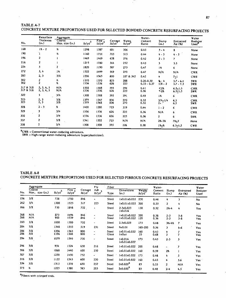
87
TABLE A-7 CONCRETE MIXTURE PROPORTIONS USED FOR SELECTED BONDED CONCRETE RESURFACING PROJECTS
Resurface eg Aggrate Water- Water Thickness Coarse Fine Cemt Wate Cement Slump Entrained Reduer
No. (in.) Max. size (in.) Ib/yd ib/yd Ib/yd Ib/yd Ratio (in.) Air (%) Used
168 114-2 Y2 1298 1587 681 306 0.45 3-4 8 None 190 1 V2 1160 1711 705 315 0.44 4-5 4-5 None 196 2 1 1469 1469 658 276 0.42 2- 3 7 None 216 2 1 1275 1780 564 252 0.45 3 3.5 None 224 5 2 1820 1190 587 275 0.47 1Y2 6 None 272 3, 4 114 1522 1499 569 270 0.47 N/A N/A CWR 285 2, 3 3/8 1206 1365 800 337 & 342 0.42 4 7+1 CWR 302 2 Y2 1370 1370 823 288 0.26-0.30 Y4 - 4 5.7 - 6.1 SWR 302 2 Va 1536 1536 626 225 0.33- 0.37 1/8 - 2 5.7 - 7.5 SWR 317 & 318 2, 3, 4, 5 N/A 1508 1508 595 291 0.41 <214 6.5+1.5 CWR 317 & 318 2, 3, 4, 5 N/A 1536 1536 626 225 0.36 <214 6.51.5 SWR 322 3 3/4 1508 1508 595 291 0.49 lYa 6 CWR 323 2, 3 3/8 1379 1347 836 270 0.32 3/4+1/4 6.5 CWR 323 2, 3 3/8 1379 1368 836 270 0.32 2+ T 6.5 SWR 328 2- 3 Va 1400 1280 725 319 0.44 1 -2 6 CWR 329 3 3/4 1536 1536 626 225 0.36 N/A 6 CWR 332 2 3/4 1536 1536 626 225 0.36 2 6 SWR 337 2 3/8 1541 1202 725 N/A N/A 214-314 714+2 None 338 2 3/4 1508 1508 595 226 0.38 134+14 6.5±1.5 CWR
aCWR = Conventional water-reducing admixture. SWR High-range water-reducing admixture (superplasticizer).
TABLE A-8 CONCRETE MIXTURE PROPORTIONS USED FOR SELECTED FIBROUS CONCRETE RESURFACING PROJECTS
Aggregate Fly Fiber Water- Water
No. Coarse Max. (in.) size
Fine Cemejlt Ash Dimensions Weigt Cement Slump Entrained Reducer Ib/yd Ib/yd Ib/yd Ib/yd Type (in.) Ib/yd Ratio (in.) Air (%) Used
256 3/8 728 1700 846 - Steel 10.010.022 250 0.46 4 5 No 262 3/4 1200 1525 517 225 Steel 10.010.022 200 0.53 2 4 No 266 3/8 750 1848 752 - Steel 2.50.025 150 0.52 234-4 4 Yes
IxO .0 16 268 N/A 873 1494 846 - Steel 10.010.022 200 0.38 2-3 5-8 Yes 268 N/A 900 1539 846 - Steel 10.010.022 120 0.36 2-3 5-8 Yes 283 3/8 1000 1500 752 - Steel 2.50.025 175 0.48 334-434 7 Yes 284 3/8 1348 1353 519 231 Steel YzxO.Ol 160-200 0.56 3 4-6 Yes 286 3/8 1206 1365 800 - Steel 10.010.022 160 0.43 4 7 Yes 286 3/8 1106 1306 800 - Glass lxflat 55 0.68 2 7 Yes 294 3/8 1079 1595 750 - Steel lxO.016 175 0.45 2-3 5 Yes
10.010.022 296 3/8 954 1324 658 216 Steel 10.010.022 200 0.48 - 7 Yes 306 3/8 1068 1440 600 250 Steel 10.010.022 160 0.59 234 1 Yes 307 3/8 1250 1450 752 - Steel 10.010.022 175 0.48 4 5 Yes 316 3/8 1122 1543 600 250 Steel 10.010.022 160 0.43 4 5.6 Yes 334 3/8 1315 1370 650 252 Steel 20.020a 85 0.53 2 N/A Yes 373 Va 1225 1380 583 203 Steel 2xO.O2Oa 85 0.48 2-4 4.5 Yes
aFibers with crimped ends.

88
TABLE A-9 BOND STRENGTH MEASUREMENTS -BONDED CONCRETE RESURFACINGS
Thick- ness Year Year Bond Strength (psi) No. o
a f
No. Type (in.) Constr. Tested Mm. Max. Avg. Cores Curing Procedure Used
1 PC 114 1913 1953 188 484 330 3 N/A
2 PC 3 1914 1953 0 208 98 3 N/A
59 PC 2 1936 1953 484 640 562 2 N/A
64 PC 2 1938 1953 348 500 404 3 Wet cotton mats for 6 days.
74 PC 314 1942 1953 444 480 462 2 Damp sand cover for 7 days.
75 PC 1 - 134 1942 1953 0 520 259 4 Damp sand cover for 7 days.
107 PC 4 1948 1953 0 348 218 3 N/A
1.08 PC 4 1948 1953 0 186 93 2 N/A
110 PC 4 1949 1953 0 168 84 2 N/A
117 Shotcrete 34 1950 1953 - - 256 1 No cover or compound used - air cured.
125 PC 2 1951 1952 - - 275 10 Vapor proof paper for 7 days.
140 PC 14 - 2 1952 1953 408 836 565 7 Wet burlap - 1 day, vapor-proof paper - 3 days, curing compound.
141 PC 1 1952 1953 316 596 445 3 Hay and tarpaulins for 10 days - cold weather.
196 PC 2 1957 1964 468 525 496 2 Water fog and wet burlap - 72 hours, curing compound.
210 PC 4 1959 1964 321 343 332 2 Curing compound..
213 PC 3 1959 1964 .0 750 459 3 Wet burlap - 72 hours, curing compound.
218 PC 5 1961 1964 224 468 346 2 White-pigmented curing compound.
222 PC 2 1962 1964 312 460 386 2 N/A
225 PC 2 1963 1964 320 406 363 2 N/A
302 PC 2 1976 1976 - - 1074 10 b 302 PC 2 1976 1977 - - 839 10 b
302 PC 2 1976 1979 - - 715 7 b
317A PC & RC 214 & 3 1977 1977 505 696 600 2 Curing compound - 2 times normal rate - 2 applications.
318A PC 2 1977 1977 366 593 488 5 318B PC 2, 3, 4, 5 1977 1977 183 449 359 7
318C PC 2, 3,4 1977 1977 310 887 585 15
318D PC 2,3 1977 1977 282 839 559 14
322 PC 3 1978 1978 - - 577 5 Curing compound - 134 times normal rate - 2 applications.
324 PC 8 1978 1978 c c 641 - Liquid membrane-forming compound at normal rate.
329 PC 3 1979 1979 - - 550 17 Curing compound - 134 times normal rate - 2 applications.
332 PC 2 1979 1979 371 851 544 8 White-pigmented curing compound.
338 PC 2 1980 1980 - - 399d - Curing compound - 114 times normal rate - 2 applications.
aPC = plain concrete; RC = reinforced concrete. bAll but 400 ft cured by curing compound at 2 times normal rate (0.13 gal/sy) applied in two applications. 400 ft cured with wet burlap
for 48 hours and then covered with polyethylene for an additional 48 hours.
C31 percent coefficient of variation.
dAverage of tests conducted at 2-7, 14, and 28 days.
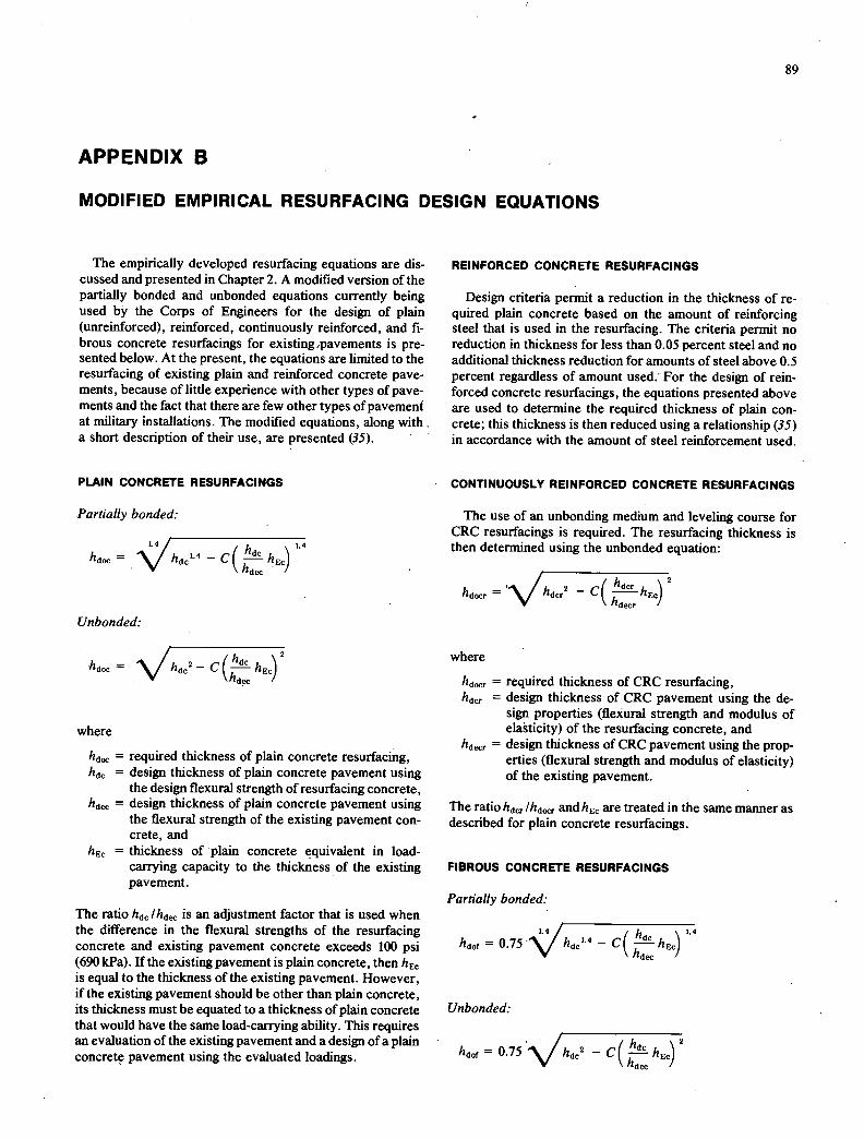
APPENDIX B
MODIFIED EMPIRICAL RESURFACING DESIGN EQUATIONS
89
The empirically developed resurfacing equations are dis-cussed and presented in Chapter 2. A modified version of the partially bonded and unbonded equations currently being used by the Corps of Engineers for the design of plain (unreinforced), reinforced, continuously reinforced, and fi-brous concrete resurfacings for existing pavements is pre-sented below. At the present, the equations are limited to the resurfacing of existing plain and reinforced concrete pave-ments, because of little experience with other types of pave-ments and the fact that there are few other types of pavement at military installations. The modified equations, along with a short description of their use, are presented (35).
PLAIN CONCRETE RESURFACINGS
Partially bonded:
L4
=
1.4
- c( hdC hEC I
hd /
Unbonded:
hd. = - c (! hEC V hd. /
where
hd ,, = required thickness of plain concrete resurfacing, hdC = design thickness of plain concrete pavement using
the design flexural strength of resurfacing concrete, hd = design thickness of plain concrete pavement using
the flexural strength of the existing pavement con-crete, and
hEC = thickness of plain concrete equivalent in load-carrying capacity to the thickness of the existing pavement.
The ratio hdC lhdll is an adjustment factor that is used when the difference in the flexural strengths of the resurfacing concrete and existing pavement concrete exceeds 100 psi (690 kPa). if the existing pavement is plain concrete, then h EC is equal to the thickness of the existing pavement. However, if the existing pavement should be other than plain concrete, its thickness must be equated to a thickness of plain concrete that would have the same load-carrying ability. This requires an evaluation of the existing pavement and a design of a plain concrete pavement using the evaluated loadings.
REINFORCED CONCRETE RESURFACINGS
Design criteria permit a reduction in the thickness of re-quired plain concrete based on the amount of reinforcing steel that is used in the resurfacing. The criteria permit no reduction in thickness for less than 0.05 percent steel and no additional thickness reduction for amounts of steel above 0.5 percent regardless of amount used: For the design of rein-forced concrete resurfacings, the equations presented above are used to determine the required thickness of plain con-crete; this thickness is then reduced using a relationship (35) in accordance with the amount of steel reinforcement used.
CONTINUOUSLY REINFORCED CONCRETE RESURFACINGS
The use of an unbonding medium and leveling course for CRC resurfacings is required. The resurfacing thickness is then determined using the unbonded equation:
hd = - c( 2
/
where
hdocr = required thickness of CRC resurfacing, hdcr = design thickness of CRC pavement using the de-
sign properties (flexural strength and modulus of elasticity) of the resurfacing concrete, and
hdecr = design thickness of CRC pavement using the prop-erties (flexural strength and modulus of elasticity) of the existing pavement.
The ratio hdcr Ihdr and hEC are treated in the same manner as described for plain concrete resurfacings.
FIBROUS CONCRETE RESURFACINGS
Partially bonded:
hdO f 0.75 ~-C( hd. \ 1.4
—hEC ) hd /
Unbonded:
hdOf = 0.75 .\/h2 -C(d
ft !. hECyhd

90
The equations for required thickness (hdOf) of fibrous con- full-scale testing. In these tests, it was found that for corn-
crete resurfacings are the same as those for plain concrete parable flexural strengths, the thickness of fibrous concrete resurfacmgs except that the resurfacing thickness is reduced could be reduced by 25 percent. It should be recognized that
by 25 percent through the use of the factor 0.75. The factor h dC is the design thickness of plain concrete having the design
has been derived from performance tests using accelerated flexural strength of the fibrous concrete resurfacing.
THE TRANSPORTATION RESEARCH BOARD is an agency of the National Research Council, which serves the National Academy of Sciences and the Na-tional Academy of Engineering. The Board's purpose is to stimulate research concerning the nature and performance of transportation systems, to disseminate information that the research produces, and to encourage the application of appropriate research findings. The Board's program is carried out by more than 250 committees, task forces, and panels composed of more than 3,100 administrators, engineers, social scientists, attorneys, educators, and others concerned with transportation; they serve without compensation. The program is supported by state transportation and highway departments, the modal administrations of the U.S. Department of Transportation, the Association of American Railroads, and other organizations and individuals interested in the development of transportation.
The Transportation Research Board operates within the National Research Council. The National Research Council was established by the National Academy of Sciences in 1916 to associate the broad community of science and technology with the Academy's purposes of furthering knowledge and of advising the Federal Government. The Council operates in accordance with general policies determined by the Academy under the authority of its congressional charter of 1863, which establishes the Academy as a private, nonprofit, self-governing membership corporation. The Council has become the principal operating agency of both the National Academy of Sciences and the National Academy of Engineer-ing in the conduct of their services to the government, the public, and the scientific and engineering communities. It is administered jointly by both Academies and the Institute of Medicine.
The National Academy of Sciences was established in 1863 by Act of Congress as a private, nonprofit, self-governing membership corporation for the furtherance of science and technology, required to advise the Federal Government upon request within its fields of competence. Under its corporate charter the Academy established the National Research Council in 1916, the National Academy of Engineering in 1964, and the Institute of Medicine in 1970.
TRANSPORTATION RESEARCH BOARD National Research Council
2101 Constitution Avenue, N.W.
Washington, D.C. 20418
ADDRESS CORRECTION REQUESTED
NON-PROFIT ORG. U.S. POSTAGE
PAID WASHINGTON, D.C. PERMIT NO. 42970
V) -
k
:
cw UJw -- "
QLU