Results on U(IV)/MA(III) co-precipitation studies for MA ...
210
RESULTS ON U(IV)/MA(III) CO-PRECIPITATION STUDIES FOR MA-BEARING OXIDE SOLID SOLUTION SYNTHESIS ACTINIDE AND FISSION PRODUCT PARTITIONING AND TRANSMUTATION – © OECD/NEA 2010 1 Results on U(IV)/MA(III) co-precipitation studies for MA-bearing oxide solid solution synthesis Jean-Philippe Dancausse, Stéphane Grandjean, Nathalie Herlet, Carole Viallesoubranne, Caroline Léorier, Benedict Arab Chapelet, Olivier Conocar Commissariat à l’Énergie Atomique Centre de Marcoule, France Abstract Within the framework of minor actinide management, the French reference way is their separation and their transmutation in fast reactors. One of the options for the transmutation is the heterogeneous mode, using actinide oxide on a uranium matrix located at the periphery of the core (“transmutation blanket”). The objective of the work is to study a precipitation process leading to the formation of U(IV)/MA(III) compound, with concentration of MA in the range 5-20%. In the case of americium and curium solid solution, for which an actinide content of less than 20% of U+MA is aimed, the oxalic co-precipitation of a solution U(IV)/MA(III) is studied. This process was not previously realised on a uranium/americium and/or curium mixture but the principle of oxalic co-precipitation of the III and IV oxidation levels has already been validated on U(IV)/Pu(III) mixtures. The main objective of tests carried out in 2006-2007 on C11/C12 Atalante hot cell was to validate the oxalic co-precipitation of U(IV)/Am(III) and/or Cm(III) by exacerbating the radiolysis phenomena through the use of 10% Cm of mass U+MA. This presentation describes the qualification steps of the process into hot cell from (U,Ce) precipitation with surrogate solution to the co-precipitation of a U(IV)/Cm(III) solution leading to a mixed oxalate U-Cm and then, after calcination under inert atmosphere, to the solid solution (U,Cm)O 2 having the fluorite structure type.
Transcript of Results on U(IV)/MA(III) co-precipitation studies for MA ...

RESULTS ON U(IV)/MA(III) CO-PRECIPITATION STUDIES FOR MA-BEARING OXIDE SOLID SOLUTION SYNTHESIS
ACTINIDE AND FISSION PRODUCT PARTITIONING AND TRANSMUTATION – © OECD/NEA 2010 1
Results on U(IV)/MA(III) co-precipitation studies for MA-bearing oxide solid solution synthesis
Jean-Philippe Dancausse, Stéphane Grandjean, Nathalie Herlet, Carole Viallesoubranne, Caroline Léorier, Benedict Arab Chapelet, Olivier Conocar
Commissariat à l’Énergie Atomique Centre de Marcoule, France
Abstract Within the framework of minor actinide management, the French reference way is their separation and their transmutation in fast reactors. One of the options for the transmutation is the heterogeneous mode, using actinide oxide on a uranium matrix located at the periphery of the core (“transmutation blanket”). The objective of the work is to study a precipitation process leading to the formation of U(IV)/MA(III) compound, with concentration of MA in the range 5-20%.
In the case of americium and curium solid solution, for which an actinide content of less than 20% of U+MA is aimed, the oxalic co-precipitation of a solution U(IV)/MA(III) is studied. This process was not previously realised on a uranium/americium and/or curium mixture but the principle of oxalic co-precipitation of the III and IV oxidation levels has already been validated on U(IV)/Pu(III) mixtures. The main objective of tests carried out in 2006-2007 on C11/C12 Atalante hot cell was to validate the oxalic co-precipitation of U(IV)/Am(III) and/or Cm(III) by exacerbating the radiolysis phenomena through the use of 10% Cm of mass U+MA. This presentation describes the qualification steps of the process into hot cell from (U,Ce) precipitation with surrogate solution to the co-precipitation of a U(IV)/Cm(III) solution leading to a mixed oxalate U-Cm and then, after calcination under inert atmosphere, to the solid solution (U,Cm)O2 having the fluorite structure type.

RESULTS ON U(IV)/MA(III) CO-PRECIPITATION STUDIES FOR MA-BEARING OXIDE SOLID SOLUTION SYNTHESIS
2 ACTINIDE AND FISSION PRODUCT PARTITIONING AND TRANSMUTATION – © OECD/NEA 2010
Introduction
Within the framework of minor actinide management, the French reference way is their separation and their transmutation in fast reactors. One of the options for the transmutation is the heterogeneous mode, using actinide oxide on a uranium matrix located at the periphery of the core (“transmutation blanket”). The objective of the work is to study a precipitation process leading to the formation of U(IV)/MA(III) compound, with concentration of MA in the range 5-20%.
In the case of americium and curium solid solution, for which an actinide content of less than 20% of U+MA is aimed, the oxalic co-precipitation of a solution U(IV)/MA(III) is studied. This process was not previously realised on an uranium/americium and/or curium mixture but the principle of oxalic co-precipitation of the III and IV oxidation levels has already been validated on U(IV)/Pu(III) mixtures.
The main objective of tests carried out in 2006-2007 on C11/C12 Atalante hot cell was to validate the oxalic co-precipitation of U(IV)/Am(III) and/or Cm(III) by exacerbating the radiolysis phenomena trough the use of 10% Cm of mass U+MA.
The important steps of this demonstration are the obtaining of a single phase mixed oxalate U-Cm and after calcination under inert atmosphere the obtaining of the aimed single phase solid solution (U,Cm)O2.
Experimental details
Reagents Uranium(IV) and curium(III) or Ce(III) surrogate solutions were prepared respectively from purified monometallic solution and by dissolving monometallic oxide. Hydrazinium nitrate (N2H5
+,NO3–) was
used as anti-nitrous agent to stabilise the +IV oxidation state of uranium. The solution characteristics (concentration, purity, oxidation state, …) were mainly determined using ICP, radiometric and spectroscopic methods.
Hot cell facility Studies were realised in the C11/C12 shielded cell of the Atalante facility. It is constituted of eleven working place behind one meter of concrete and lead glasses. The versatility of this hot cell has permitted to achieve all the required steps to obtained (U0.9,Cm0.1)O2 solid solution: radioactive solution purification (240Pu removal coming from 244Cm decay), precipitation and calcination as well as some on-line or in situ measurements.
Synthesis methods The synthesis of mixed-oxide of uranium and curium was realised by a batch oxalic precipitation in a vortex effect vessel (REV), under the following conditions (Figure 1):
• realisation of approximately 2 g of (U,Cm)O2 at 10% in Cm mass compared to (U+Cm);
• co-precipitation of oxalate of U(IV)/Cm(III) by simultaneous addition of:
– nitric solution of U (IV) (stabilised with hydrazine) and Cm (III) titrating approximately 40 g/L of actinides;
– oxalic acid and hydrazinium nitrate mixture;
– in an oxalic acid and hydrazinium nitrate in nitric medium, representative of the composition of the oxalic natural brines to balance;
• filtration of the obtained mixed oxalate;
• calcination of oxalate at 700°C under a neutral argon atmosphere.

RESULTS ON U(IV)/MA(III) CO-PRECIPITATION STUDIES FOR MA-BEARING OXIDE SOLID SOLUTION SYNTHESIS
ACTINIDE AND FISSION PRODUCT PARTITIONING AND TRANSMUTATION – © OECD/NEA 2010 3
Figure 1: Experimental conditions of uranium and curium oxalate batch co-precipitation
U(IV)-Cm(III) Co-conversion Cm/(U+Cm) = 10 % (at./at.)
Actinide feed solutionUIV
CmIII
HNO3N2H5
+
Flow rate : 5 mL.min-1
Volume : 30 mLREV
Volume : 200 mLStirring : 450 tr.min-1
oxalic acid feed solutionH2C2O4N2H5
+
Flow rate : 5 mL.min-1
Volume : 30 mL
Initial solutionH2C2O4HNO3N2H5
+
Volume : 60 mL
The precipitation vessel and filtration are described below (Figures 3, 5 and 6). For the calcination step, a horizontal tubular furnace was used. The oxalate powder is placed inside a quartz vessel under an argon flow as shown in Figure 2.
Figure 2: Details of calcination set-up
Experiment realisation
Before the realisation of experiment using curium, a test under the real conditions (Figure 3) of hot cell was performed using uranium and cerium. The criterion retained to validate this step was the single phase structure of both oxalate and oxide after calcination. The obtained X-ray pattern is presented on Figure 4, confirming the efficiency of the retained experimental design for hot cell test using curium.

RESULTS ON U(IV)/MA(III) CO-PRECIPITATION STUDIES FOR MA-BEARING OXIDE SOLID SOLUTION SYNTHESIS
4 ACTINIDE AND FISSION PRODUCT PARTITIONING AND TRANSMUTATION – © OECD/NEA 2010
Figure 3: Hot cell precipitation set-up
Figure 4: Diffraction pattern of U-Ce oxide cfc single phase
UCeO2UCeO2
Demonstration on uranium and curium
All the steps described below were realised in one day.
U and Cm solution were mixed half an hour before the beginning of the precipitation leading to a feed solution having the following characteristics:
• feed volume: 30 mL;
• [U]: 40 g/L;
• [Cm]: 3.65 g/L.
The precipitation step itself as described above in Figure 1, took about 7 min. (Figure 5) with an average flow of 4.3 mL/min and the ageing step about 20 min. After the filtration (Figure 6), rinsing

RESULTS ON U(IV)/MA(III) CO-PRECIPITATION STUDIES FOR MA-BEARING OXIDE SOLID SOLUTION SYNTHESIS
ACTINIDE AND FISSION PRODUCT PARTITIONING AND TRANSMUTATION – © OECD/NEA 2010 5
and partial drying operations, nearly 2 g of oxalate precipitate were recovered (Figures 7 and 8). Then, after two hours argon sweeping of calcination set-up, the oxalate was heated up to 720°C and maintained at this temperature for three hours. The resulting oxide weighing was 0.95 g.
Figure 5: Precipitation step
Figure 6: Filtration step

RESULTS ON U(IV)/MA(III) CO-PRECIPITATION STUDIES FOR MA-BEARING OXIDE SOLID SOLUTION SYNTHESIS
6 ACTINIDE AND FISSION PRODUCT PARTITIONING AND TRANSMUTATION – © OECD/NEA 2010
Figure 7: Filter and oxalate powder recovery
Figure 8: Crucible filling with oxalate powder
Results
Chemical balance The efficiency of the process was evaluated considering initial and final solution contents. Less than 0.03% of initial curium remains in the filtrate solution leading to a calculated atomic ratio Cm/U slightly above 10% in the resulting solid.
Powder characteristics
X-ray diffraction
The X-ray diffraction pattern obtained on oxide shows a well-defined single phase corresponding to the expected fluorite type structure. The calculated lattice parameter is equal to 54.49 nm.

RESULTS ON U(IV)/MA(III) CO-PRECIPITATION STUDIES FOR MA-BEARING OXIDE SOLID SOLUTION SYNTHESIS
ACTINIDE AND FISSION PRODUCT PARTITIONING AND TRANSMUTATION – © OECD/NEA 2010 7
Figure 9: Diffraction pattern of U0.9-Cm0.1 O2 cfc single phase
Lin
(Cou
nts)
0
1000
2000
3000
4000
2-Theta - Scale9 10 11 12 13 14 15 16 17 18 19 20 21 22 23 24 25 26 27 28 29 30
U0.9Cm0.1O2
Lin
(Cou
nts)
0
1000
2000
3000
4000
2-Theta - Scale9 10 11 12 13 14 15 16 17 18 19 20 21 22 23 24 25 26 27 28 29 30
U0.9Cm0.1O2
Scanning electron microscopy observations
The SEM examinations of oxalate and oxide powders exhibit nearly the same morphology for both. The slight difference (average particle size) is mainly due to the mass loss during thermal treatment.
Figure 10: (U,Cm) oxalate agglomerate
Figure 11: (U,Cm)O2 agglomerate

RESULTS ON U(IV)/MA(III) CO-PRECIPITATION STUDIES FOR MA-BEARING OXIDE SOLID SOLUTION SYNTHESIS
8 ACTINIDE AND FISSION PRODUCT PARTITIONING AND TRANSMUTATION – © OECD/NEA 2010
Conclusion
The co-conversion process applied to U(IV)-Cm(III) solution with a ratio 90/10 led as expected to a fluorite single-phase oxide. This experiment will be continued by studying the effects of 244Cm alpha irradiation on structure and lattice parameters of this oxide as a function of time.
Further experiments will be oriented to study the synthesis of fluorite structure solid solutions containing different ratios and mixtures of U, Pu, Np, Am and Cm in several grams scales in the framework of minor actinide transmutation studies.
References
Grandjean, S., et al., World Patent, WO 2005/119699 (2005).
Grandjean, S., et al., “Structure of Mixed U(IV)-An(III) Precursors Synthesized by Co-conversion Methods”, presented at Plutonium Futures 2008 and forthcoming in Journal of Nuclear Materials.

SAFETY RESEARCH FOR MULTI-FUNCTIONAL REPROCESSING PROCESS BASED ON ION-EXCHANGE METHOD
ACTINIDE AND FISSION PRODUCT PARTITIONING AND TRANSMUTATION – © OECD/NEA 2010 1
Safety research for multi-functional reprocessing process based on ion-exchange method*
S. Koyama,1 M. Ozawa,1,4 K. Okada,2 Y. Sato,2 K. Kurosawa,3 K. Tatenuma,3 T. Suzuki,4 Y. Fujii4
1Japan Atomic Energy Agency 2National Institute of Advanced Industrial Science and Technology,
3KAKEN Co., Ltd. 4Tokyo Institute of Technology
Abstract The group separation of lanthanide (Ln) and actinide (An), and the mutual separation of americium (Am) and curium (Cm) are still unfinished assignment as an optional separation scheme concerned with current aqueous reprocessing process. We proposed a multi-functional separation process on the basis of an ion-exchange method using tertiary pyridine type resin. Hot experiment of total separation process, starting from fuel dissolution by using a fragment of a spent mixed-oxide (MOX) fuel which had been highly irradiated in the experimental fast reactor JOYO, was demonstrated at the Alpha-Gamma Facility (AGF) of Japan Atomic Energy Agency (JAEA). We could achieve separations of the five groups, i.e. platinum group elements, Ln fission products, fuel elements (U, Pu and Np), Am and Cm. The process is a key technology for Advanced ORIENT Cycle concept implemented by JAEA as a fundamental research programme on separation, transmutation and utilisation of nuclides in the nuclear spent fuel. In order to apply this process to engineering scale, two important subjects should be solved so as to prove the availability. One is explication of the reactive safety between ion exchange resin (IER) and solvent (conc. HNO3 – MeOH and HCl). The other is engineering aspect for the use of conc. HCl solution, because of its corrosive property to the material.
Thermal hazards of the pyridine-type IER/MeOH – HNO3 eluent and HCl system were examined from the viewpoints of fire and explosion safety. First, a fundamental analysis of IER was conducted, and was analysed the chemical reactions of the IER/MeOH – HNO3 eluent system. Second, we applied a differential scanning calorimeter (DSC) to evaluate thermal hazards of the IER/MeOH – HNO3 eluent and HCl system. Third, gram-scale heat experiment was performed to confirm the actual thermal hazard.
It is well known that HCl is corrosive solvent towards structural materials made of stainless steel, and therefore, optimised structural metal should be used for components and equipment. Four metals, tantalum (Ta), zirconium (Zr), niobium (Nb) and hastelloy which is a nickel-based alloy (Ni-28Mo), were selected as candidate structural materials. The conventional austenitic stainless steel SUS316L was used as a reference. Corrosion experiment at room temperature and 90°C using liquid HCl was performed to observe the corrosion rate and soluble elements from the matrix and corroded structure. And moreover, we made electrochemical measurements to evaluate corrosion mechanism. In this meeting, these results will be reported.
* The full paper being unavailable at the time of preparation of this CD-ROM, only the abstract is included.

RECOVERY OF ACTINIDES FROM A LIQUID CATHODE BY A CADMIUM DISTILLATION
ACTINIDE AND FISSION PRODUCT PARTITIONING AND TRANSMUTATION – © OECD/NEA 2010 1
Recovery of actinides from a liquid cathode by a cadmium distillation
S-W. Kwon, Y-J. You, S-W. Paek, K-R. Kim, S-H. Kim, J-B. Shim, H. Chung, D-H. Ahn, H-S. Lee, E-H. Kim
Korea Atomic Energy Research Institute Daejeon, Korea
Abstract In Korea, the studies on a partitioning have been focused on the development of pyroprocessing based on an electrorefining of actinides because it is a kind of proliferation-resistive technology, where all the transuranic metals are separated together as a mixture. Electrorefining is generally composed of two recovery steps – deposit of uranium onto a solid cathode and the recovery of actinide elements by a liquid cadmium cathode. The actinides in the liquid cadmium cathode are generally collected as an ingot by an evaporation of cadmium at a reduced pressure. In this study, cadmium distillation experiments were carried out to examine the behaviour of a cadmium distillation for the development of an actinide recovery process from a liquid cadmium cathode. The experimental set-up is composed of an evaporator, condenser, vacuum pump, control unit, and an off gas treatment system. The evaporation temperature was varied from 400 to 700°C. Cadmium was successfully distilled and separated from the surrogate actinide metals. The evaporation rate were measured and compared with the values calculated by a relation based on the kinetics of gases. The theoretical value of the evaporation rate calculated by the Hertz-Langmuir relation is higher than the experimental value. This deviation was compensated by an evaporation coefficient obtained empirically. The evaporation coefficient was a function of the temperature.

RECOVERY OF ACTINIDES FROM A LIQUID CATHODE BY A CADMIUM DISTILLATION
2 ACTINIDE AND FISSION PRODUCT PARTITIONING AND TRANSMUTATION – © OECD/NEA 2010
Introduction
It is needed to separate long-lived actinides from the rest of the spent nuclear fuel to recycle them in a transmutation process [1]. The long-lived actinides could be extracted and fabricated into a fuel for use in advanced reactors. In addition, the extraction of actinides from a spent fuel will significantly reduce the radioactivity of the spent fuel and the volume of the spent fuel to be buried in a repository.
Pyroprocessing has been developed for the separation of the long-lived elements due to its advantages of a compactness, a nuclear proliferation resistance, and a reduction of a secondary waste generation [1].
Electrorefining is a key step in a pyroprocessing. Electrorefining process is generally composed of two recovery steps – deposit of uranium onto a solid cathode and the recovery of the remaining uranium and TRU elements simultaneously by a liquid cadmium cathode. After the recovery step of the actinides by the liquid cadmium cathode, cadmium is separated from the actinide products in liquid cadmium cathode by a distillation process [2]. Distillation process is adopted due to the following advantages [3]:
• minimal generation of secondary waste;
• compact unit process;
• simple, low -cost equipment;
• large pyrochemical experience pool;
• cost effective vs. other alternatives.
Physical separation process, such a distillation separation, is more attractive than chemical or dissolution process because physical processes generate much less secondary process. Besides the nuclear industry, cadmium distillation process has other applications in purification of cadmium and waste treatment of spent Ni-Cd battery [4,5].
In this study, cadmium distillation experiments were carried out to examine the behaviour of cadmium evaporation for the development of an actinide recovery process from the actinide-loaded liquid cadmium cathode.
Experimental
Figure 1 shows the layout of the experimental set-up for the cadmium distillation. The experimental set-up is composed of an evaporator, a condenser, a control unit, and an off gas treatment system. The evaporation area is surrounded by a carbon dome with an inner diameter of 200 mm. The maximum heating temperature is 1 500°C. The temperature in the carbon dome was measured by using a thermocouple that is connected to the centre of the dome. A Kanthal super heating element is used for heating the evaporation area.
The loading capacity is 1 kg-Cd/batch. Cadmium ingot was cut into small pieces and used as received without any further treatment. The cadmium ingot has a purity of 99.99 wt.%. The condenser is connected to the rotary vacuum and diffusion pumps. The diffusion pump was used to remove oxygen in the evaporator and the condenser chamber before a evaporation of cadmium. The absolute vacuum pressure can be reached below 1 × 10⁻³ torr before a heating. The vacuum pressure was measured by a MKS Baratron pressure sensor and a readout system. A filter was used to avoid contact between the cadmium vapour and the pressure sensor. Weight loss of cadmium in the crucible was measured by a load cell. The distillation experiments were performed in a vacuum at various temperatures in the range of 400-700°C. The ceramic filter was placed before the vacuum pump to avoid an entrainment of cadmium vapour to the pump. The off gas from the distiller was treated in the wet scrubber before its release to the atmosphere.
The cadmium crucible with about 170 g of cadmium is bottom loaded into the carbon dome by raising the bottom assembly until seated. The evaporator was evacuated and heated up to the distillation temperature. The temperature was held until a complete evaporation of the cadmium for the isothermal experiments, whereas the temperature rises continuously in the non-isothermal

RECOVERY OF ACTINIDES FROM A LIQUID CATHODE BY A CADMIUM DISTILLATION
ACTINIDE AND FISSION PRODUCT PARTITIONING AND TRANSMUTATION – © OECD/NEA 2010 3
experiments. Cadmium vapour was transported to the condenser through a 2″ diameter pipe which is preheated by a jacket heater. Cadmium is recovered by allowing the vapour to strike a cold receiving crucible, where it condenses.
Results and discussion
An investigation on the cadmium evaporation behaviour is important for the development of an actinide recovery process from a liquid cadmium cathode. Distillation rates at each temperature are very important parameters for the design and decision on an operation mode of a cadmium distiller. However, the data on the evaporation rates is not available at various temperatures, even though there have been some cadmium distillation studies [2,6].
The distillation separation process can be modelled by the kinetic theory of gases [7]. From this theory, the rate of the mass of a gas incident on a unit area per unit time can be calculated by a so called Hertz-Langmuir equation. The rate of evaporation is related to the vapour pressure of a substance. The Hertz-Langmuir relation is given as follows [Eq. (1)]:
M = (Pi – Pa)/(2πmRT)0.5 (1)
where M is the net vaporisation rate, m is the molecular weight, R is the gas constant, T is the temperature, Pi is the saturation vapour pressure of gas i in an ambient space, and Pa is the partial pressure of gas i in an ambient space.
As shown in Figure 2, the evaporation rate of cadmium (a) and the time-cumulated amounts of evaporated cadmium at constant temperatures (b) were calculated by Hertz-Langmuir relation. The evaporation rate increases exponentially with an increasing temperature. The distillation rate of cadmium was varied from 105 to 6 330 g/h-cm2 in the temperature range of 400-600°C.
Cadmium distillation experiments were carried out to examine the behaviour of a cadmium separation and to compare the experimental evaporation rate with the calculated value. Figure 3 shows profiles of cadmium weight loss and temperature during an evaporation experiment at 500°C. The distillation rate of cadmium increased with an increasing temperature.
The distillation rate of cadmium was varied from 5 to 35 g/h-cm2 in the temperature range of 400-700°C. Due to the low rate, 400°C seems to be too low to be a distiller operating temperature. It was also reported that the distillation temperature of 400°C was too low to evaporate 10 g of Cd metal in a limited time of 2 h [6].
The measured evaporation rate was compared with the values calculated by a Hertz-Langmuir equation. The theoretical value calculated by the Hertz-Langmuir relation is much higher than the experimental value of the evaporated cadmium as shown in Figure 5. This high value is probably explained by the fact that the model does not consider the effects such as a transfer of a vapour and a heat transfer. The Hertz-Langmuir equation assumes that the distillation rate is solely controlled by the vaporisation at the surface and ignores such factors as the rate of a vapour transport, heat transfer at the surface, and the presence of impurities.
Westphal, et al. investigated the evaporation rate of LiCl-KCl eutectic salt and found that the ratio of measured to theoretical is on the same order, that is, approximately 10% [8]. Bourges, et al. studied on the distillation of a KCl and CaCl2 salt system [9]. The ratio of the measured to theoretical is about 6 to 8% for both KCl and CaCl2. They reported that the actual rate of the distillation is determinate not solely by the rate of the evaporation from the surface as by the rate of transfer of the vapour away from the surface. Moreover, parameters such as the heat transfers, retro-diffusion phenomena, impurities and mixing interactions are ignored by the Langmuir expression. Thus the apparent rates are less than the theoretical rates.
This deviation between the actual and calculated distillation rate is compensated by an evaporation coefficient (α) obtained empirically. The evaporation coefficient was a function of temperature as shown in Eq. (2):
392713 T*10*47.4T*10*15.1T*10*61.1583.0 −−− −+−−=α (2)

RECOVERY OF ACTINIDES FROM A LIQUID CATHODE BY A CADMIUM DISTILLATION
4 ACTINIDE AND FISSION PRODUCT PARTITIONING AND TRANSMUTATION – © OECD/NEA 2010
Distillation rate varies with vapour pressure, which is dependent on temperature. The evaporation coefficient decrease with the increasing temperature as shown in Figure 4. The evaporation coefficients of cadmium distillation range from 0.043 to 0.0025 in the temperature range of 400 to 650°C.
The evaporation rates measured by non-isothermal method are similar to the values of the isothermal method. After the distillation experiment, a residue remained in the process crucible. The residue was found to be CdO as shown in Figure 7. The residue was about 0.10-0.25 g at each run. This amount corresponds to about 0.05 to 0.15% of the initial cadmium ingot loaded into the crucible.
Summary
Distillation behaviour of cadmium at a reduced pressure was investigated to develop an actinide recovery process from a liquid cadmium cathode in a laboratory scale cadmium distiller. Distillation rate of cadmium was calculated by the Hertz-Langmuir relation based on the kinetic theory of gases. Distillation experiments of cadmium were carried out by isothermal and non-isothermal methods and compared with a theoretical value. The theoretical value calculated by the Hertz-Langmuir relation is higher than experimental value of evaporated cadmium. This high value is probably explained that the model does not consider the effects such as transfer of vapour, heat transfer. This deviation is compensated by an evaporation coefficient (α) obtained empirically and the evaporation coefficient was a function of the temperature. About 0.1-0.25 wt.% of residue was left in the crucible after the distillation and found to be CdO.
References
[1] Laidler, J.J., J.E. Battles, W.E. Miller, J.P. Ackerman, E.L. Carls, Progress in Nuclear Energy, Vol. 31, p. 131 (1997).
[2] Westphal, B.R., J.C. Price, D. Vaden, R.W. Benedict, J. Alloys and Compounds, 444-445, 561 (2007).
[3] “Separation of Plutonium from Chloride Salts is Demonstrated by High-temperature Vacuum Distillation Method”, The Actinide Research Quarterly: Spring 1996, LALP-95-79.
[4] Ali, S.T., J.V. Rao, K.S. Varma, T.L. Prakash, Bull. Mater. Sci., 25, 479 (2002).
[5] Cox, A., D.J. Fray, Trans. Inst. Min. Metall., 108, C153 (1999).
[6] Kato, T., M. Iizuka, T. Inoue, T. Iwai, Y. Arai, J. Nucl. Mater., 340, 259-265 (2005).
[7] Dushman, S., Scientific Foundations of Vacuum Technique, 2nd Ed., John Wiley and Sons, New York (1962).
[8] Westphal, B.R., D. Vaden, T.Q. Hua, J.L. Willit, D.V. Laug, “Recent Development at the Cathode Processor for Spent Fuel Treatment”, American Nuclear Society Fifth Topical Meeting, Charleston, South Carolina, USA, 17-20 September 2002.
[9] Bourges, G., D. Lambertin, C. Baudrot, L. Pescayre, C. Thiebaut, “Development of a Vacuum Distillation Process for Pu Pyrochemistry Spent Salts Treatment”, ATALANTE 2004, Nîmes, France, 21-25 June 2004.

RECOVERY OF ACTINIDES FROM A LIQUID CATHODE BY A CADMIUM DISTILLATION
ACTINIDE AND FISSION PRODUCT PARTITIONING AND TRANSMUTATION – © OECD/NEA 2010 5
Figure 1: Experimental set-up for the cadmium distillation experiments
H eaterPri mary Cr uc i bl e
L oad Cell
H eater Unit
Cool ing
Jack et P ipe
Cd condensin g
cr uc ibl e Vacuum Pump
Cooli ng IN /OUT
I nsul at ion
H eaterPri mary Cr uc i bl e
L oad Cell
H eater Unit
Cool ing
Jack et P ipe
Cd condensin g
cr uc ibl e Vacuum Pump
Cooli ng IN /OUT
I nsul at ion
Figure 2: The evaporation rate (a) and the amount of evaporated cadmium (b) calculated by Hertz-Langmuir relation
(a) (b)
Temperature [K]500 600 700 800 900 1000
W [g
/h-c
m2 ]
0
5000
10000
15000
20000
25000
30000
Time [hr]0 1 2 3 4 5
Am
ount
Eva
pora
ted[
g/cm
2 ]
0
2000
4000
6000
8000
10000
12000
14000
400oC500oC600oC700oC

RECOVERY OF ACTINIDES FROM A LIQUID CATHODE BY A CADMIUM DISTILLATION
6 ACTINIDE AND FISSION PRODUCT PARTITIONING AND TRANSMUTATION – © OECD/NEA 2010
Figure 3: Weight loss profile during the cadmium distillation experiment at 500°C
Temperature[K]650 700 750 800 850 900 950
Dis
tilla
tion
rate
[g/h
r/cm
2 ]
1
10
100
Figure 4: Distillation rate of cadmium at various temperatures
Time[h]0 1 2 3 4 5 6 7
Wei
ght [
g]
0
50
100
150
200
Tem
p[o C
]
0
100
200
300
400
500
600
WeightTempT- pv
Figure 5: Comparison between the experimental and calculated distillation rates
Temperature[K]500 600 700 800 900 1000
Dis
tilla
tion
rate
[g/h
-cm
2 ]
1
10
100
1000
ExperimentalH-L eqn(α=1)

RECOVERY OF ACTINIDES FROM A LIQUID CATHODE BY A CADMIUM DISTILLATION
ACTINIDE AND FISSION PRODUCT PARTITIONING AND TRANSMUTATION – © OECD/NEA 2010 7
Figure 6: Effect of temperature on the evaporation coefficient
Temperature [K]
650 700 750 800 850 900 950
α
0.00
0.01
0.02
0.03
0.04
0.05
Rsqr =1.00
Figure 7: XRD pattern of the residue in the crucible after distillation
2θ
10 20 30 40 50 60 70
Inte
nsity
[arb
uni
ts]
●●
●
●
●
● CdO

MULTI-FUNCTIONAL REPROCESSING SYSTEM TOWARD FUTURE NUCLEAR FUEL CYCLE
ACTINIDE AND FISSION PRODUCT PARTITIONING AND TRANSMUTATION – © OECD/NEA 2010 1
Multi-functional reprocessing system toward future nuclear fuel cycle*
M. Ozawa,1,2 T. Suzuki,1 S. Koyama,2 I. Yamagishi,2 R. Fujita,3 H. Mimura,4 Y. Fujii1
1Tokyo Institute Technology 2Japan Atomic Energy Agency
3Toshiba Corporation 4Tohoku University
Abstract A Trinitarian R&D strategy (Adv. ORIENT Cycle) on separation, transmutation and utilisation of nuclides in the nuclear spent fuel has been actualised at the step of laboratory scale study. Deep and direct separation of all of actinides till to pure Am and Cm products by tertiary pyridine resin, selective separation of Cs and Sr by novel nano ion-exchangers and electrochemical separation of rare metal fission products (RMFP: Ru, Rh, Pd, Tc, Se, Te, Ag, etc.) are the main key technologies composing a multi-functional reprocessing system in Adv.ORIENT Cycle. Isotope separation of long-lived fission product (LLFP) toward the transmutation is also included as a challenge for the advancement in the separation of radioactive nuclides. Some of fission products like RMFP, in addition to the actinides, must be second products in the future reprocessing system because their abundance in highly burned fast breeder reactor (FBR) spent fuel versus possible requirement by the industries will be significantly noticeable in future. In a proposed multi-functional reprocessing, ion exchange chromatography (IXC) and electrochemical techniques are applied in combination under the nitric and hydrochloric acid media for better separation. At the system, three steps of separation were employed fundamentally under the hydrochloric acid media. The RMFP and Cs/Sr will be separated from main actinide fraction by tertiary pyridine resin at the first step, and further refined toward their utilisation by catalytic electrolytic extraction (CEE) method. In the applied CEE, specific metallic cation such as Pd2+, which originates in the solutions, may act as promoters (i.e. Pdadatom) or mediators, thereby accelerating electrochemical deposition of Ru, Rh and Re (simulator Tc). In the nitric acid media, though the maximum deposition ratios of RMFP were rather low for Ru, Re and Tc, deposition ratios of all of RMFP were significantly improved to be >90% in hydrochloric media. In the second step, three fractions like MA/Ln with other FP/Pu were obtained, and Am/Cm separation was successfully attained at the third step by methanol-nitric acid media, finally. Electro-deposited electrodes were dedicated to water (alkali or sea water) electrolysis tests for hydrogen production. The mixture Pd-Ru-Rh-Re deposit electrodes showed high catalytic reactivity than that of Pt-black electrode, thereby suggesting them to be alternated with the existing catalysts for hydrogen generation. To answer a few engineering issues pointed out to the proposed separation processes under the hydrochloric media, thermo-chemical safety of the resin at either nitric acid or hydrochloric acid environment, and new anti-corrosive material in hydrochloric media will be discussed in reference with the existing PUREX data. The proposed separation system composed of IXC and CEE would be the candidate for multi-functional reprocessing in future, or the ad hoc separation of Am/Cm and/or specific RMFP in the conventional PUREX-TRUEX system if they are individually applied to.
* The full paper being unavailable at the time of preparation of this CD-ROM, only the abstract is included.

ELECTROCHEMICAL REDUCTION OF U3O8 POWDER IN A MOLTEN LiCl-Li2O SALT
ACTINIDE AND FISSION PRODUCT PARTITIONING AND TRANSMUTATION – © OECD/NEA 2010 1
Electrochemical reduction of U3O8 powder in a molten LiCl-Li2O salt
Byung Heung Park, Il Woo Lee, Jin-Mok Hur, Hansoo Lee Korea Atomic Energy Research Institute, Korea
Abstract Pyroprocessing has been developed for partitioning metal fuels and, recently, the application of a pyroprocessing has been extended to an oxide spent fuel. In order to accept oxide fuels into an existing electrorefining process which was originally developed for metallic spent fuels, a reduction process compatible with the electrorefining process is required. Korea Atomic Energy Research Institute has investigated a molten-salt-based electrochemical reduction technology for oxide spent fuels under consideration of a conditioning or recycling or both. An electrochemical reduction process was carried out in a molten LiCl-Li2O salt using a porous magnesia basket. A metal oxide to be reduced was loaded into a nonconductive ceramic basket and acted as a cathode. Platinum was adopted as an inconsumable anode. In this work, U3O8 powder has been electrochemically reduced to uranium metal at 650°C in molten LiCl-3 wt.% Li2O, and the characteristics of the electrochemical reduction such as the potential profiles were measured using a bench-scale electro-reducer of a 10g U3O8/batch scale. The reduction runs were carried out by changing the current and the amount of charges supplied to a cell. It was found that the potential was stable from the start when the current density exceeded around 150 mA/cm2. An XRD analyser was used to detect the kind of lithium uranate during the reduction.

ELECTROCHEMICAL REDUCTION OF U3O8 POWDER IN A MOLTEN LiCl-Li2O SALT
2 ACTINIDE AND FISSION PRODUCT PARTITIONING AND TRANSMUTATION – © OECD/NEA 2010
Introduction
A pyrochemical reduction technology for oxide spent fuels was developed on the base of a chemical process using a reductant such as a lithium metal in a molten salt. However, a chemical reduction process requires an additional process to produce a reductant, and a transportation of the reactive material should be included to connect these two processes; a reduction process and a reductant recovery process. Recently, an electrochemical technique has been applied to the reduction of oxide spent fuels, which has some advantages over the conventional chemical processes. In the Korea Atomic Energy Research Institute (KAERI), an advanced spent fuel conditioning process (ACP) has been proposed and developed to reduce the volume, heat load, and radiotoxicity of processed SF. An electrolytic reduction process is a main process of the ACP, where oxides are converted into a metallic form, and the heat-generating elements such as Cs and Sr are readily removed from the reduced product by being dissolved in a chloride salt.
The electrolytic reduction process in the ACP was designed to have an integrated cathode which is composed of a metallic current lead, the oxides to be reduced, and a ceramic basket containing the oxides in the form of a powder. In the present study, electrochemical reduction behavior of U3O8 powder was investigated by adjusting the currents and charges supplied to a cell in a 10g U3O8/batch scale reactor, to understand the electrochemical reduction behavior of uranium oxide in a molten LiCl salt.
Experimental and results
A 10 g U3O8/batch scale electrochemical reactor has a flange with seven ports; one for an integrated cathode, three for anodes, one for a reference electrode, one for a thermocouple and one for a salt sampling. An integrated cathode was located at the centre of the reactor, which was composed of a SUS rod as a current lead, a porous magnesia filter (OD = 21 mm, ID = 16 mm) for a powder containment, and the U3O8 powder to be reduced. Three anodes made of platinum tubes (OD = 6 mm) were placed at the same distance from the cathode, and a platinum rod (OD = 3 mm) was used as a quasi-reference electrode.
The mixed salt of LiCl and Li2O was prepared by adding Li2O from Alfa AESAR Co. to a fused LiCl to be 3 wt.% of Li2O in 220 g of LiCl under an inert atmosphere. A power was applied by a WMPG 1000 Multichannel Potentiostat/Galvanostat from WonA-Tech between an integrated cathode where 10 g of U3O8 was loaded and three anodes which were made of platinum. Different initial current densities from 26.5 to 212.2 mA/cm2 were applied and the amounts of supplied charge were changed by controlling the run times under a constant current condition. The reduced products were recovered after each run and the reduction yields were determined by measuring the weight gains using a thermogravimetirc method with a TG/DTA 6300 of Seiko Instruments Inc.
At the 212.2 mA/cm2 condition, the reduction yield was increased in proportion to the amount of supplied charges. However, a linear correlation between the charges and the reduction yields was not found for the other conditions. A mass transfer of Li2O is thought to be a reason for the experimental results. Therefore, in order to sustain an electrochemical reduction, a current should exceed a threshold value which might be dependent on a system. As a qualitative analysis of the recovered products, an XRD analysis was used and a mixed oxide in the form of lithium uranates was found during the process of making the metallic uranium.
Summary
In KAERI, an electrochemical reduction technology has been developed as a part of an ACP for a volume reduction. Using a LiCl-3 wt.% Li2O molten salt as an electrolyte, a 10 g U3O8/batch scale electrochemical experimental was carried out to study the reduction behaviour of U3O8. By changing the current density and the amount of charges supplied to a cell, the reduced product was obtained and analysed to reveal there is a critical current density to sustain a reduction. The critical density is expected to be lowered by adjusting the electrode configuration and other system specifications. During the U3O8 reduction in a molten LiCl-3 wt.% Li2O salt, a mixed oxide of lithium uranate was found and it can be considered as an intermediate product prior to a metallic uranium production.

PARTITIONING AND TRANSMUTATION IN SCANDINAVIA – CHALMERS GROUP
ACTINIDE AND FISSION PRODUCT PARTITIONING AND TRANSMUTATION – © OECD/NEA 2010 1
Partitioning and transmutation in Scandinavia – Chalmers Group
Emma Aneheim,1 Christian Ekberg,1,2 Anna Fermvik1, Mark St.J. Foreman,1,2 Jan-Olov Liljenzin,1 Teodora Retegan,1 Gunnar Skarnemark1
1Nuclear Chemistry, 1Industrial Materials Recycling Department of Chemical and Biological Engineering
Chalmers University of Technology Gothenburg, Sweden
Abstract The waste from nuclear power plants all over the world has to be isolated from man and his environment for about 100 000 years to be considered safe. It has been suggested that if the long-lived actinides could be separated from the spent fuel the isolation time could be shortened to about 1 000 years. This, however, requires selective separation of parts of the waste. In this area important progress has been gained along the years.
The Nuclear Chemistry group at Chalmers has almost 50 years of experience in solvent extraction and was one of the first institutes to investigate basic properties of extraction systems. This includes the development of reprocessing processes. Chalmers scientists have recently actively participated in numerous partitioning projects within the EU Framework Programmes.
The experiments carried out at Chalmers contribute to the final goal of partitioning and transmutation in Europe, which is a working separation plant for spent nuclear fuel for further transmutation to achieve shorter disposal times and more efficient use of the nuclear fuel.
The experience gained working with the European consortium on the partitioning and transmutation will assist the Scandinavian countries with their spent fuel reprocessing/management policy.

PARTITIONING AND TRANSMUTATION IN SCANDINAVIA – CHALMERS GROUP
2 ACTINIDE AND FISSION PRODUCT PARTITIONING AND TRANSMUTATION – © OECD/NEA 2010
The University of Technology
Chalmers University of Technology was founded in 1829 under the name “Chalmersska Slöjdskolan” (Chalmers School of Handicrafts) following a donation from the estate of William Chalmers (1748-1811) who was one of the directors of the famous Swedish East India Company in Gothenburg. In 1937 the Chalmers School became a university with the authority to award doctoral degrees owned by a foundation directed by the freemasons in Gothenburg. In 1963 it was totally taken over by the government and in 1994 Chalmers University of Technology became a private university again, now owned by a new foundation.
Today more than 10 000 people including 2 000 employees, 7 000 undergraduates and 1 000 graduate students work and/or study in some of the universities, schools or departments and divisions. The research performed at Chalmers University of Technology ranges from natural sciences to engineering, mathematics and community development.
Besides PhD (Doctor of Philosophy) programmes the university offers Master of Science Engineering, Master of Architecture, Bachelor of Engineering and Nautical programmes. Every year Chalmers’ International Master’s programmes also attract more than 3 000 students from over 100 countries. Chalmers has many international collaboration projects of which one is the Alliance for Global Sustainability (AGS) consisting of joint research with ETH (Zurich), MIT (Boston) and Tokyo University [1].
The division
The research groups of Nuclear Chemistry as well as the closely related research group of Industrial Materials Recycling are parts of the Department of Chemical and Biological Engineering at Chalmers. The two groups together consist of seven senior researchers (professors, assistant professors and doctors), two professor emeritus, eleven doctoral students and a varying number of diploma workers as well as technical and administrative staff, with the major part related to Nuclear Chemistry.
Every year there are undergraduate courses given in basic and applied nuclear chemistry and advanced computer programming that are attended by approximately forty students. On demand graduate courses are also given in solvent extraction chemistry and actinide chemistry. The Nuclear Chemistry division has almost 50 years of experience in solvent extraction and was one of the first laboratories in the world where experiments regarding quantitative solvent extraction were made to gain basic knowledge of equilibrium constants and extraction processes [2].
History To develop the new field of nuclear energy in Sweden the department of Nuclear Chemistry was established in 1945, as part of a three-pronged approach to develop nuclear energy in Sweden. The director of the “Laboratory for Applied Nuclear Chemistry in Gothenburg” was given the title of professor by the government. Originally the research mainly consisted of basic nuclear chemistry such as investigations of the solid state, the use of radioactive nuclides as tracers in solution chemistry and the development of radiation detectors. In the late 1950s the research focus changed more towards properties of nuclear fuels and reprocessing chemistry.
In 1962 the first professor in Nuclear Chemistry at Chalmers was appointed by the Swedish government. Research on solid state materials was now largely replaced by research on the solution chemistry of the actinides and fission products. In the late 1960s there was also research performed in the area of materials recycling for the first, but not last, time in the divisions’ history. For instance industrial processes for metal recycling using solvent extraction were developed. From the mid-1970s the research also included final storage of spent fuel and radioactive waste. This part of the research grew during the 1970s and 1980s at the expense of materials recycling which eventually disappeared.
In the early 1990s the work at the department diversified to also include nuclear reaction studies, research on severe nuclear reactor accidents, and on separation and transmutation. During the entire 1970s and 1980s there was also a lot of research done on fast solvent extraction separations to study nuclear and chemical properties of short-lived fission products and trans-actinides. These activities were suspended in the 1990s due to lack of funding. In the 2000s the research on final storage has

PARTITIONING AND TRANSMUTATION IN SCANDINAVIA – CHALMERS GROUP
ACTINIDE AND FISSION PRODUCT PARTITIONING AND TRANSMUTATION – © OECD/NEA 2010 3
become a smaller part of the research while the research on nuclear reactors, basic solution chemistry and solvent extraction has grown. In 2007 the research on materials recycling was also revived with the start of a new division called Industrial Materials Recycling that works in close collaboration with the Nuclear Chemistry division. To give an example on how these two subjects can be related one can mention the research on separation for transmutation which is the perfect bridge between the two divisions since it includes large parts from both areas [3].
Present work
The work carried out in the division of Nuclear Chemistry today ranges over many different areas in the field of nuclear chemistry, e.g. complexation chemistry, separation and transmutation, fuel chemistry, medical applications, super heavy elements, the chemistry of severe nuclear accidents, fundamental solvent extraction, fundamental actinide chemistry and radio analytic chemistry [4].
Not only partitioning and transmutation of nuclear waste is studied at the division but there are also ongoing studies regarding a geological disposal. This is to provide society with a balanced view of the different disposal options. Currently the once through fuel strategy is employed in Sweden and a deep geological disposal is planned. Studies on deep storage will not be obsolete even if the partitioning and transmutation option is selected at a later date since work on the deep repository includes geochemical calculations (groundwater/mineral reactions and interactions with engineering materials in water environments), sorption, diffusion, precipitation, dissolution and corrosion.
Partitioning and transmutation The waste from nuclear power plants all over the world has to be isolated from man and his environment for about 100 000 years to be considered safe. It has been suggested that if the long-lived actinides could be separated from the rest of the spent fuel the storage time could be shortened to about 1 000 years [5,6]. This, however, requires selective separation of parts of the waste. By separating the elements they can be treated in different ways and hence the amount and radiotoxicity of the waste can be lowered. For example, some of the long-lived nuclides can be bombarded with neutrons and through nuclear reactions other nuclides that are more short-lived or even stable can be formed; so called transmutation.
Twenty-five years ago a partitioning and transmutation (P&T) group at Chalmers studied separation and transmutation as means to reduce the radiotoxicity of certain actinides that are to be found in the waste flows from processing plants. This research started again about 10 years ago as part of an EU project, NEWPART, followed by PARTNEW and then EUROPART. The fourth EU framework project in the area of separation and transmutation, ACSEPT, has been running since March 2008 and the Chalmers group is participating [7,8].
Today the research group consists of one professor, one assistant professor and four doctoral students. The specialties and also main tasks for the group are to synthesise, test and evaluate new extraction and stripping reagents for the separation of trivalent actinides and lanthanides. Recently there has also been research performed in the transmutation area by one of the group’s members at the European Commission Joint Research Centre: Institute for Trans Uranium elements (ITU) in Germany. The group’s main focus however lies on the separation process of trivalent actinides and lanthanides using nitrogen donor ligands such as those of the molecule type BTBP (Figure 1). These molecules, which follow the CHON-principle (containing only carbon, hydrogen, oxygen and nitrogen) [10] and therefore are fully combustible, thus simplifying the disposal and treatment of secondary wastes, will hopefully have future use in an industrialised process for P&T in Europe.
Figure 1: BTBP-type molecule (Bis Triazinyl BiPyridine)
N NN
NN N
N
N
R R
R R

PARTITIONING AND TRANSMUTATION IN SCANDINAVIA – CHALMERS GROUP
4 ACTINIDE AND FISSION PRODUCT PARTITIONING AND TRANSMUTATION – © OECD/NEA 2010
The new extraction agents are evaluated regarding several different aspects. They are, together with different diluents, tested for extraction properties of An/Ln (distribution ratios and separation factors), dissolution properties, kinetics of extraction and resistance to ionising radiation (different doses and different types of radiation).
One example of experiments performed within the partitioning and transmutation group at Chalmers is the influence of diluents on the An(III) extraction with BTBP-type molecules. Figure 2 shows an example of the results from such a study.
Figure 2: Test of diluents for the separation of Am(III) and Eu(III) with CyMe4-BTBP
D = distribution ratio, SF = separation factor
Beside the areas mentioned above there are also other possibilities for useful research that can be conducted at the division in the separation and transmutation area: theoretical calculations on a molecular level for both the metal-ligand interactions and modelling of the complex-diluent interactions, process flow sheet calculations and small scale process plants based on mixer-settlers or centrifugal contactors.
Equipment To be able to perform all of the work described above the group uses the following recourses available at the Nuclear Chemistry division [2]:
• α-laboratory for work with macro amounts of alpha-emitting radio nuclides (equipped with glove-boxes, spectrophotometer (UV-VIS), ultracentrifuge (280 000), microscope, oven (2000°C), etc., and with the possibility to do experiments under inert atmosphere). The only one in Sweden
• Organic synthesis laboratory.
• Laboratories for conducting work with radioactive materials.
• 60Co cell for irradiation and radiolysis tests.
• Radiation detectors: HPGe detector systems (γ), surface barrier detectors (α), liquid scintillation detectors (α and β), SiLi-detector (soft γ and X-rays), NaI(Tl) scintillation detector (γ), and various gas-filled detectors.
• Two AKUFVE systems (one-stage mixer-settler for continuous analysis on liquid-liquid extraction systems, near absolute phase separation).

PARTITIONING AND TRANSMUTATION IN SCANDINAVIA – CHALMERS GROUP
ACTINIDE AND FISSION PRODUCT PARTITIONING AND TRANSMUTATION – © OECD/NEA 2010 5
• Two mixer-settler batteries (of different materials) with controls.
• ICP-MS and ICP-OES.
• Hot cell laboratory for γ activity. The only one in a university in Sweden.
Conclusion
On medium term, the experiments carried out at Chalmers are contributing to the final goal of the partitioning and transmutation in Europe, which is a working separation plant for spent nuclear fuel for further transmutation to achieve shorter disposal time and more efficient use of the nuclear fuel.
On longer term, the experience gained working with the European consortium on partitioning and transmutation will assist the Scandinavian countries with their spent fuel reprocessing/ management policy, if ever decided.
References
[1] Chalmers University of Technology, CTH Informationssekretariatet, Annual Report 2007, ISSN: 0281-6224.
[2] ACSEPT official webpage, Chalmers Tekniska Hoegskola Aktiebolag, [accessed 18/08/2008]: www.acsept.org/acsept.php?page=partner&npart=CHALMERS&tree0=Members&tree1=Partner%20Details&orig=membersbyname&mem=By%20name.
[3] Chalmers official webpage, Kärnkemi-Vår Historia, 11/06/2007, [accessed 18/08/2008]: www.chalmers.se/chem/SV/amnesomraden/karnkemi/var-historia.
[4] Chalmers official webpage, Kärnkemi-Forskningsområden, 11/09/2007, [accessed 18/08/2008], Available: www.chalmers.se/chem/SV/amnesomraden/karnkemi/forskningsomraden.
[5] Aoki, S., “Research and Development in Japan on Long-lived Nuclide Partitioning and Transmutation Technology”, Progress in Nuclear Energy, 40, 3-4, 343-348 (2002).
[6] Madic, C., M.J.Hudson, J-O., Liljenzin, J-P. Glatz, R. Nannicini, A. Facchini, Z. Kolarik, R. Odoj, New Partitioning Techniques for Minor Actinides, EUR 19149, European Commission, Luxembourg.
[7] Chalmers official webpage, Transmutation, 17/10/2007, [accessed 18/08/2008]: www.chalmers.se/chem/SV/amnesomraden/karnkemi/forskningsomraden/transmutation.
[8] Bourg, S., E. Touron, C. Caravaca, C. Ekberg, E. Gaubert, C. Hill, “ACSEPT: A New FP7-Euratom Collaborative Project in the Field of Partitioning Processes for Advanced Fuel Cycles”, ATALANTE 2008, Montpellier, France, 19-22 May 2008, Communication reference number: O1-02.
[9] Madic, C., M.J. Hudson, High Level Liquid Waste Partitioning by Means of Completely Incinerable Extractants, Final Report, European Commission Contract No. FI2W-CT91-0112, EUR 18038 (1998).

COUNTER-CURRENT EXTRACTION AND SEPARATION OF Nd FROM Sr, Zr AND Pd BY TDdDGA
ACTINIDE AND FISSION PRODUCT PARTITIONING AND TRANSMUTATION – © OECD/NEA 2010 1
Counter-current extraction and separation of Nd from Sr, Zr and Pd by TDdDGA, N,N,N′,N′-tetradodecyl-diglycolamide
Yuji Sasaki, Toshihide Asakura, Yoshihiro Kitatsuji, Yasuji Morita, Takaumi Kimura Japan Atomic Energy Agency, Japan
Abstract Diglycolamide, DGA, compounds have the strong extractability for trivalent, tetravalent and hexavalent actinides (An) from nitric acid to n-dodecane, therefore DGA is one of the candidate extractants for the recovery of An from high-level radioactive liquid waste. Since DGA connecting with the long alkyl chain, TDdDGA (N,N,N′,N′-tetradodecyl-diglycolamide), has high extraction capacity and suppresses to form the third phase with Nd, we used TDdDGA to demonstrate the counter-current extraction, prior to the hot test. In this experiment we use four elements, i.e. Sr, Pd, Zr and Nd, as the typical fission products and a representative ion of An(III) and lanthanides, to confirm the extraction and separation properties, because these four elements are extractable by TDdDGA. After determination of the optimum condition on the extraction and separation of Nd from other elements by the calculation using D values, we perform the counter-current extraction using the mixer-settler equipment.

COUNTER-CURRENT EXTRACTION AND SEPARATION OF Nd FROM Sr, Zr AND Pd BY TDdDGA
2 ACTINIDE AND FISSION PRODUCT PARTITIONING AND TRANSMUTATION – © OECD/NEA 2010
Introduction
Due to the environmental safety, economical process development and transmutation, it is considered that the long lived alpha emitters, e.g. minor actinides (MA) including Am and Cm, in high-level radioactive waste solution (HLW) have to be recovered quantitatively, these nuclides will be transmutated to be short-lived nuclides or disposed in the environmental setting. Recently, MA separation is one of the key works in the nuclear fuel reprocessing and partitioning. The new extractants has been widely reported, and the representative reagents, CMPO, malonamide and TODGA, were used to establish the chemical process for MA separation. Among these, TODGA (N,N,N′,N′-tetraoctyl-diglycolamide) has very high distribution ratio (D) for MA from HNO3 to n-dodecane [1-3], and this reagent is a promising extractant for the partitioning of HLW, however, a few studies on process development using TODGA were carried out until now [4-5].
From the study on loading capacity of TODGA, the quantitative extraction of MA and lanthanides (Ln) in HLW is hardly achieved due to the third phase formation, therefore Modolo, et al. have employed the condition of 0.2 M TODGA + 0.5 M TBP/TPH (TetraPropylene Hydrogenated) as the extraction solvent in order to suppress the crud formation and to increase the extraction capacity [4]. We found that diglycolamide (DGA) compounds having the long alkyl chain gives high extraction capacity without the third phase formation [6-7].
In the present study, we use TDdDGA (N,N,N′,N′-TetraDodecyl-diglycolamide) for the new reagent of MA extraction. This extractant is used in the counter-current extraction and the effective condition and the process availability are investigated.
Experimental
Chemicals The reagents used for the synthetic experiments and the solvent extraction were commercially available. TDdDGA compounds of more than 98% purities were purchased from Kanto Chemical Co. Inc. The standard solutions of metal ions [Sr(II), Zr(IV), Pd(II) and Nd(III)] for atomic absorption spectrometry (Wako Pure Chemical Industries, Ltd) were used. All the other reagents, e.g. HNO3, H2O2 and Na2EDTA (ethylenediamine-N,N,N′,N′-tetraacetic acid disodium salt) and n-dodecane were of an analytical grade.
Batch extraction procedure A certain volume (0.5-1 ml) of the organic phase was taken in an extraction tube with an equal volume of an aqueous nitric acid solution spiked with 10 μl of radioactive tracer solution or the metal standard solution. The concentrations of metal ions used in the batchwise extraction were 100 ppm for Sr(II), Mo(VI), Zr(IV), Pd(II) and Ru(III), 1 ppm for Tc(VII), 5 × 10⁻² ppm for Th(IV), 0.1 ppm for U(VI), 1 × 10⁻² ppm for Np, 6 × 10⁻⁵ ppm for Pu, 3 × 10⁻⁴ ppm for Am(III), and 1 × 10⁻⁵ ppm for Cm(III). The extraction tube containing two phases was shaken mechanically for 30 min to reach the equilibrium at 25 ± 0.1°C. Np and Pu were reduced and adjusted to Np(IV) and Pu(III) by addition of H2O2. After centrifuging and separating both phases, the duplicate 0.50 ml aliquots were taken and their activities were measured by NaI scintillation counter (COBRA 5003, Packard Instrument Company) for 241Am, liquid scintillation counter (Tri-Carb 1600 TR, Packard Instrument Company) for 99Tc, 230Th, 233U, 237Np, 238Pu, and 244Cm with 5 ml of PICO-AQUA cocktail. The amounts of non-radioactive metal ion in the sample solutions prepared from both phases were measured by ICP-AES (SPS 1200AR, Seiko-EG & G).
Counter-current extraction TDdDGA/n-dodecane concentration to be 0.1 M (=mol/dm3) was used for the extraction solvent and 1 M HNO3 + 0. 2M H2O2 + 0.02 M Na2EDTA was used for the feed and scrub solutions. This condition would separate Nd from Sr, Zr and Pd, which was shown by a simple simulation calculation. All four metal ions can be extracted by TODGA [8], Zr and Pd are readily to form the crud and Sr would be separated from Nd as a heat source. The concentrations of metal ions in the feed are: Sr; 0.78 mM, Zr; 2.99 mM, Pd; 3.71 mM and Nd; 16.6 mM. HNO3 with the concentration of 0.2 M is employed as the

COUNTER-CURRENT EXTRACTION AND SEPARATION OF Nd FROM Sr, Zr AND Pd BY TDdDGA
ACTINIDE AND FISSION PRODUCT PARTITIONING AND TRANSMUTATION – © OECD/NEA 2010 3
aqueous solution for the back-extraction of Nd. The flow sheet design of counter-current extraction showing the extraction stage number and flow rate of the aqueous and organic phases is illustrated in Figure 1. After experiments, the metal concentrations in each extraction stage were measured by ICP-AES.
Figure 1: Flow sheet of counter-current extraction
Extraction solvent 120 cm3 h-1
0.1 M TDdDGA/n-dodecaneScrub: 60 cm3 h-1
1 M HNO3/ 0.2M H2O2/ 0.02 M Na2EDTA
Sr, Zr, Pd
Nd
Extraction (8 stages) Scrub (8 stages)
Back-extraction (8 stage)
Raffinate180 cm3 h-1
Nd product120 cm3 h-1
Used solvent150 cm h-1
Back-extraction 120 cm3 h-1
0.2 M HNO3
Nd, Sr, Zr, Pd
extraction (4 stage)
extraction solvent for scrub, 30 cm3 h-1
0.1 M TDdDGA/n-dodecane
Results and discussion
Extraction of An and FP by TDdDGA Extraction of An and FP in the extraction system of TDdDGA/n-dodecane and HNO3 with 0.2 M H2O2 were shown in Figure 2. H2O2 can work as a reductant of Np. It is noted that the distribution ratio (D) of Np is suddenly increased from 2 M HNO3 according to the redox reaction of NpO2
+ + 4H+ + e–
⇔ Np4+ + 2H2O, the proton may support the reduction of Np and Np(IV) is ready to extract by TDdDGA. Therefore, high HNO3 concentration give high Np(IV)/Np(V) ratio and show high D(Np). On the other hand, D(Zr) is relatively low in comparison to that without H2O2. H2O2 is a famous ligand for Mo complexation, in this case Zr may form metal-complex with H2O2, is stabilised in the aqueous phase, and show low D values. From these results, H2O2 can be used to extract Np and suppress Zr extraction, and no specific change can be seen in extraction of other metal ions by addition of H2O2.
Figure 2: Extraction of An and FP by TDdDGA
10-3
10-1
101
103
105
10-1 100 101
U(VI)Np(IV)Pu(III)Am(III)Cm(III)
D(A
n)
HNO3 concentration/ M
Aqueous phase: HNO
3 +
0.2M H2O
2
Organic phase: 0.1M TDdDGA /n-dodecane
10-3
10-1
101
103
105
10-1 100 101
U(VI)Np(IV)Pu(III)Am(III)Cm(III)
D(A
n)
HNO3 concentration/ M
Aqueous phase: HNO
3 +
0.2M H2O
2
Organic phase: 0.1M TDdDGA /n-dodecane
10-3
10-1
101
103
105
10-1 100 101
Ca
Sr
Pd
Tc
Zr
Ba
La
Nd
Eu
D(F
P)
HNO3 concentration/ M
Organic phase: 0.1M TDdDGA /n-dodecaneAqueous phase: HNO
3+0.2M H
2O
2

COUNTER-CURRENT EXTRACTION AND SEPARATION OF Nd FROM Sr, Zr AND Pd BY TDdDGA
4 ACTINIDE AND FISSION PRODUCT PARTITIONING AND TRANSMUTATION – © OECD/NEA 2010
Extraction capacity of TDdDGA It has already been reported that the length of the alkyl chain combined to DGA influences extraction capacity of Nd, and DGA and monoamide with more than 17 and 13 of C/O ratio, respectively, have no third phase [7,9]. In the present work, we measured LOC(Nd) using TODGA, TDDGA (N,N,N′,N′-tetradecyl-diglycolamide) and TDdDGA. Here, LOC is a limit of metal concentration in the organic phase. The results are shown in Table 1. It is evident that DGA having the long alkyl chain gave a high extraction capacity and TDdDGA has five times higher extraction capacity than that of TODGA. The extraction species of Nd with TDdDGA is considered as 1:3 (= Nd:TDdDGA) of the metal-complex, so the maximum concentration of Nd in the organic phase seems to be 33 mM when 0.1 mM TDdDGA/ n-dodecane is used. Table 1 shows that the stoichiometric extraction can be attained by TDdDGA without any modifier of diluent.
Table 1: Relationship between TO, TD, TDdDGA and extraction capacity for Nd(III)
extraction capacity (mM)TODGA 6.4TDDGA 25.8TDdDGA 32.5Condition: Extractant concentration; 0.1 M,
HNO3 concentration; 3M
Counter-current extraction of Nd and separation from Sr, Pd and Zr Using the extraction condition in Figure 1, the concentration of metal ion in the aqueous and the organic phases at each extraction stage are shown in Figures 3-6. Here, the solid lines in these figures are the results of calculation using the relationship between D(M) and HNO3 concentration. In Figure 3, Nd concentrations in the organic phases increase gradually with stage No. at the extraction section of No. 1 to 7 and shows a almost constant values from No. 7 to 16 (scrub section) stages. The Nd concentration continues decreasing at the back-extraction stage. Other metal ions, Sr, Zr and Pd, show the similar profiles with each other, high concentrations in the aqueous phases and a constant values until 8 (extraction) stages can be seen and then the concentrations decrease at the scrub stages. These results suggest the low concentrations of these metal ions in the organic phases. The scrubbing solution is an effective to eliminate these metal ions and separate from Nd. The overall recovery (%) is listed in Table 2, the Nd product contains more than 99.94% Nd, and other metal ions were separated into raffinate. The problem is a low detection limit and accuracy for Zr, and the result of Zr in Table 2 has large error. It is observed during the experiment that the white crud in extraction stage No. 1 and No. 2 were formed and increased. We have been studying the source of the crud and the condition to eliminate it, we will report these results in near future.
Figure 3: Extraction profile of Nd at each stage in counter-current extraction
0.001
0.01
0.1
1
10
100
1 2 3 4 5 6 7 8 9 10 1112 13 14 15 16 1718 19 20 21 22 23 24 25 26 27 28
()
水相実験結果
水相計算結果
有機相実験結果
有機相計算結果
Feed120 cm3 h−1
Scrub60 cm3 h−1
Back-extr.120 cm3 h−1
Extr. solvent120 cm3 h−1
Addi. Extr.30 cm3 h−1
Extr. (8) Scrub (8) B-Extr. (8)
Aq. (exp.)Aq. (cal.)Org. (exp.)Org. (cal.)
stage No.
Nd
conc
entr
atio
n (m
ol/d
m3 ) (4)
Concentration profile of Nd(III)

COUNTER-CURRENT EXTRACTION AND SEPARATION OF Nd FROM Sr, Zr AND Pd BY TDdDGA
ACTINIDE AND FISSION PRODUCT PARTITIONING AND TRANSMUTATION – © OECD/NEA 2010 5
Figure 4: Extraction profile of Sr at each stage in counter-current extraction
0.001
0.01
0.1
1
1 2 3 4 5 6 7 8 9 10 11 12 13 14 15 16 17 18 19 20 21 22 23 24 25 26 27 28
濃度
()
水相実験結果 有機相実験結果
水相計算結果 有機相計算結果
Feed120 cm3 h−1
Scrub60 cm3 h−1
Back-Extr.120 cm3 h−1
Extr. solvent120 cm3 h−1
Addi. Extr.30 cm3 h−1
Extr. (8) Scrub (8) Back-extr. (8)
Aq. (exp)Aq. (cal)
Org. (exp)Org. (cal)
Srco
ncen
trat
ion
(mol
/dm
3 )
stage No.
(4)
Concentration profile of Sr(II)
Figure 5: Extraction profile of Zr at each stage in counter-current extraction
0.01
0.1
1
10
1 2 3 4 5 6 7 8 9 10 11 12 13 14 15 16 17 18 19 20 21 22 23 24 25 26 27 28
濃度
() 水相実験結果
水相計算結果
有機相計算結果Detection limit
Feed120 cm3 h−1
Scrub soln.60 cm3 h−1
Back-extr.120 cm3 h−1
Extr. Solvent120 cm3 h−1
Addi. extr.30 cm3 h−1
Extracion (8) Scrub (8) Back-extr. (8)
Aq. (exp)Aq. (cal)Org. (cal)
stage No.Zr
conc
entr
atio
n/ m
mol
/ dm
3
(4)
Concentration profile of Zr(IV)
Figure 6: Extraction profile of Pd at each stage in counter-current extraction
0.001
0.01
0.1
1
10
1 2 3 4 5 6 7 8 9 10 11 12 13 14 15 16 17 18 19 20 21 22 23 24 25 26 27 28
Pd濃
度 (m
mol
dm
) 水相実験結果 有機相実験結果
水相計算結果 有機相計算結果
Feed120 cm3 h−1
Scrubbing60 cm3 h−1
Back-extraction120 cm3 h−1
Extr. solvent120 cm3 h−1
Addi. extr.30 cm3 h−1
Extraction (8) Scrubbing (8) Back-extr. (8)
stage No.
Pd c
once
ntra
tion/
mm
ol/d
m3
Aq. (exp)Aq. (cal)
Org. (exp)Org. (cal)
(4)
Concentration profile of Pd(II)

COUNTER-CURRENT EXTRACTION AND SEPARATION OF Nd FROM Sr, Zr AND Pd BY TDdDGA
6 ACTINIDE AND FISSION PRODUCT PARTITIONING AND TRANSMUTATION – © OECD/NEA 2010
Table 2: Recovery (%) of in the raffinate and the Nd product
Element RecoveryRaffinate Nd product Used solvent
Nd ≦0.04 ≧ 99.94 ≦0.02Sr ≧99.86 ≦0.07 〜 0Zr 76-100 (≦13) (≦13)Pd 98.2-99.6 0.4 ≦1.4
Acknowledgements The present study is the result of “Development of separation technology of transuranium elements and fission products by using new extractants and adsorbents” entrusted to the Japan Atomic Energy Agency by the Ministry of Education, Culture, Sports, Science and Technology of Japan (MEXT).
References
[1] Sasaki, Y., Y. Sugo, S. Suzuki, S. Tachimori, Solv. Extr. Ion Exch., 19, 91-103 (2001).
[2] Sasaki, Y., S. Tachimori, Solv. Extr. Ion Exch., 20, 21-34 (2002).
[3] Sugo, Y., Y. Sasaki, S. Tachimori, Radiochim. Acta, 90, 161-165 (2002).
[4] Modoro, G., H. Vijen, D. Serrano-Purroy, B. Christiansen, R. Malmbeck, C. Sorel, P. Baron, Sep. Sci. Technol., 42, 439-452 (2007).
[5] Modoro, G., H. Asp, H. Vijen, R. Malmbeck, D. Magnusson, C. Sorel, Solv. Extr. Ion Exch., 26, 62-76 (2008).
[6] Sasaki, Y., Y. Sugo, S. Suzuki, T. Kimura, Anal. Chim. Acta, 543, 31-37 (2005).
[7] Sasaki, Y., Z-X. Zhu, Y. Sugo, H. Suzuki, T. Kimura, Anal. Sci., 21, 1171-1175 (2005).
[8] Zhu, Z-X., Y. Sasaki, H. Suzuki, S. Suzuki, T. Kimura, Anal. Chim. Acta, 527, 163-168 (2004).
[9] Gasparini, G.M., G. Grossi, Solvent Extr. Ion Exch., 4, 1233 (1986).

ELECTROLYSES OF BURN-UP SIMULATED URANIUM NITRIDE FUELS AND ACTINIDE NITRIDES
ACTINIDE AND FISSION PRODUCT PARTITIONING AND TRANSMUTATION – © OECD/NEA 2010 1
Electrolyses of burn-up simulated uranium nitride fuels and actinide nitrides containing inert matrix materials in a molten LiCl-KCl eutectic
Takumi Satoh, Takashi Iwai, Yasuo Arai Japan Atomic Energy Agency, Japan
Abstract The electrolyses of burn-up simulated uranium nitride fuels containing representative solid fission product elements (Mo, Pd, Nd) and actinide nitrides containing inert matrix materials such as (U,Zr)N, (Pu,Zr)N, UN+TiN and PuN+TiN were investigated in the molten LiCl-KCl eutectic melt at 773 K from the view point of application of pyrochemical reprocessing to nitride fuel cycle. The anodic dissolution of UN in burn-up simulated UN began at about -0.75 V vs. Ag/AgCl, as well as that of pure UN. As for actinide nitrides containing inert matrix, the anodic dissolution of actinide nitrides in UN+TiN and PuN+TiN began at the similar potential of those of pure actinide nitrides because they did not form solid solution with TiN. On the other hand, the anodic dissolution of actinide nitrides in (U,Zr)N, (Pu,Zr)N began more positive potential than those of pure actinide nitrides because they formed the solid solution with ZrN and activity of them decreased.

ELECTROLYSES OF BURN-UP SIMULATED URANIUM NITRIDE FUELS AND ACTINIDE NITRIDES
2 ACTINIDE AND FISSION PRODUCT PARTITIONING AND TRANSMUTATION – © OECD/NEA 2010
Introduction
Nitride fuel cycle for transmutation of long-lived minor actinides (MA) has been developed in Japan Atomic Energy Agency (JAEA) under the double-strata fuel cycle concept [1-6]. The transmutation system proposed by JAEA is a Pb–Bi cooled sub-critical accelerator driven system with 15N-enriched MAs nitride fuels containing inert matrix such as ZrN and TiN. In this concept, spent nitride fuel from ADS is treated by pyrochemical process. Pyrochemical process has several advantages over wet process such as PUREX in treating nitride fuel for transmutation, including recycling feasibility of 15N.
In order to apply the pyrochemical reprocessing to nitride fuel cycle, Shirai, et al. elucidated the electrochemical behaviors of actinide nitrides such as UN, PuN, (U, Pu)N and NpN and successfully recovered U, Pu and Np metals by the electrolysis of their nitrides in the molten LiCl-KCl eutectic melt [7-11]. However, information on the electrolyses of actinide nitrides containing fission product (FP) elements and inert matrix materials is meager although it is necessary to clarify how FP and inert matrix affect the dissolution of actinide nitrides and to understand behavior of FP and inert matrix in the electrorefining process.
In the present work, the electrolyses of burn-up simulated uranium nitride, UN, containing representative solid fission product elements (Mo, Pd, Nd) and actinide nitrides containing inert matrix such as (U,Zr)N, (Pu,Zr)N, UN+TiN and PuN+TiN were investigated in the molten LiCl-KCl eutectic salt containing UCl3 from the view point of application of pyrochemical reprocessing to nitride fuel cycle. The experimental results on the electrode reaction of burn-up simulated uranium nitride fuels and actinide nitrides containing inert matrix materials were summarised and discussed from thermodynamic view point [12,13].
Experimental
Sample preparation Three kind of burn-up simulated UN pellets, UN+Mo (Mo = 2.84 wt.%), UN+Pd (Pd = 4.6 wt.%) and (U,Nd)N (NdN = 8.0 wt.%), were prepared by Mitsubishi Materials Corporation. UN and (U,Nd)N pellets were prepared by carbothermic reduction from UO2 or UO2 and Nd2O3 mixtures, followed by sintering. UN+Mo and UN+Pd pellets were prepared by sintering green pellets of UN and Mo or Pd mixtures. The contents of simulated fission products in the samples are adjusted to the total amounts of Mo and Tc (represented by Mo), platinum group metals (represented by Pd) and rare earth elements (represented by Nd) in spent nitride fuel with burn-up of 20% fissions per initial metal atoms (FIMA). The pellets were identified as a two-phase mixture of UN and Mo, that of UN and UPd3 and single-phase solid solution of (U,Nd)N, respectively, by X-ray diffraction and Electron Probe Micro Analyser (EPMA) analyses.
Similarly, four kind of actinide nitrides containing inert matrix pellets, (U,Zr)N (ZrN = 60 at.%), (Pu,Zr)N (ZrN = 90 at.%), UN+TiN (TiN = 60 at.%) and PuN+TiN (TiN = 94 at.%), were prepared. (U,Zr)N pellet was prepared by carbothermic reduction from UO2 and ZrO2 mixtures. (Pu,Zr)N, UN+TiN and PuN+TiN pellets were prepared by sintering green pellets of PuN and ZrN, UN or PuN and TiN mixtures, respectively. The contents of inert matrix material in (U,Zr)N and UN+TiN are adjusted to 60 at.% proposed for ADS in JAEA, while those in (Pu,Zr)N and PuN+TiN are smaller because they were prepared for the irradiation test in Japan Materials Testing Reactor (JMTR) [6]. These pellets were identified as (U,Zr)N or (Pu,Zr)N solid solution, UN or PuN and TiN two phase mixture, respectively, by X-ray diffraction and EPMA analyses.
Electrochemical measurements The electrochemical cell used in the present study was previously shown [10]. The molten LiCl-KCl eutectic salt with about 0.54 wt.% UCl3 or 1.1 wt.% PuCl3 of about 110 g was contained in an alumina crucible (about 130 cm3). UCl3 and PuCl3 were prepared by the chlorination of U or Pu metal with CdCl2 in Cd-LiCl-KCl at 773 K. The details of the procedure were described in the previous paper [14]. LiCl-KCl eutectic salt of 99.99% purity was obtained from Aldrich-APL. A cage made of Mo or W mesh (50 mesh; Rare Metallic Co. Ltd.) was used as an anode, and a 104-325 mg piece of sample pellets was placed in the cage. The counter electrode used was a W wire (1 mm in diameter, 10 mm in length) for cyclic voltammetry, a liquid Cd (about 5 g, surface area: 0.65 cm2) for electrolysis. The liquid Cd

ELECTROLYSES OF BURN-UP SIMULATED URANIUM NITRIDE FUELS AND ACTINIDE NITRIDES
ACTINIDE AND FISSION PRODUCT PARTITIONING AND TRANSMUTATION – © OECD/NEA 2010 3
cathode (LCC) was prepared as follows; some granules of Cd (99.999%; Wako Pure Chemical Industries Ltd.) were placed in separate crucibles made of high-purity alumina (99.6%; Nikkato Co.) and the crucible was immersed in the LiCl-KCl melt phase. A W wire (>99.95%; Rare Metallic Co. Ltd.) of 1.0 mm in diameter sheathed with a high-purity alumina tube of 1.0 mm in inner diameter and 2.0 mm in outer diameter was immersed in the liquid metal phase to be used as a lead wire. A silver-silver chloride (Ag/AgCl) electrode was used as a reference electrode. The reference electrode consisted of a closed-end porous mullite tube (50% Al2O3 + 46% SiO2; Nikkato Co.), in which the LiCl-KCl eutectic salt containing 5.0 mol% AgCl was placed, and an Ag wire of 1.0 mm in diameter was immersed in the salt. The temperature of the molten salt was measured to ±1.0 K using a calibrated Chromel-Alumel thermocouple.
The voltammetric measurements and electrolyses were carried out by using a potentio/ galvanostat coulometer (EG&G Princeton Applied Research, Model 263A-2). The electrolyses were performed by a potential-controlled manner. The concentrations of each metal element in the LiCl-KCl eutectic and the LCC were determined by ICP-AES after the electrolysis. The experiments were carried out in the glove boxes with Ar gas atmosphere where the impurities of oxygen and moisture were kept less than 2 ppm.
Results and discussion
Burn-up simulated UN Figure 1 shows the cyclic voltammograms for the dissolution of UN, UN+Mo, UN+Pd and (U,Nd)N in the molten LiCl-KCl eutectic salt with 0.54 wt.% UCl3 at 773 K in the potential range of -1.3 to -0.6 V. 206 mg of UN, 168 mg of UN+Mo, 205 mg of UN+Pd, 175 mg of (U,Nd)N in Mo mesh cage were used as a working electrode. UN was measured for comparison with burn-up simulated UN samples. The voltammograms of UN+Mo, UN+Pd and (U,Nd)N are similar to that of UN. The anodic current, which was caused from the reaction represented by the Eq. (1), was observed at the potential higher than about -0.75 V vs. Ag/AgCl:
-2
+3 3e+N21+U=UN (1)
Figure 2 shows the steady state anodic polarisation curves of UN+Mo, UN+Pd and (U,Nd)N in the molten LiCl-KCl eutectic salt with 0.54 wt.% UCl3 at 773 K in the potential range from -1.0 to -0.5 V. In the measurement, the chronoamperograms were measured at first at each potential for 1 min. Since the current reached a constant within 1 min at all potential, the current at 1 min was recorded at each potential. It was found that the anodic dissolutions of UN+Mo, UN+Pd and (U,Nd)N began at about -0.75 V vs. Ag/AgCl.
After the electrochemical measurements, the constant potential electrolyses at -0.65 to -0.60 V of burn-up simulated UN pellets were carried out. Results of the electrolyses are summarised in Table 1. In all samples, the concentration of U in the salt was constant and that of Mo and Pd were kept below detection limits before and after electrolysis. On the other hand, the concentration of Nd in the salt increased from 97 to 218 ppm. The increase of weight calculated from the concentration and weight of salt was 13.1 mg, which was almost equivalent of 100% of Nd contained in the initial sample. The recovery yield of U was calculated as 91-93% in all samples. On the other hand, those of Mo and Pd were below detection limits and that of Nd was calculated as 2.9%. Therefore, it was thought that most of UN was dissolved into LiCl-KCl as UCl3 at the anode, and U was recovered at the LCC in all samples. Further, most of Nd was dissolved into LiCl-KCl as NdCl3, while Mo and Pd were not dissolved and remained at the anode. However, the recovery yield of U did not reach 100% in all samples. It is considered that part of the sample dropped out from the Mo mesh electrode, because the sample became small and porous by the progress of electrolysis.

ELECTROLYSES OF BURN-UP SIMULATED URANIUM NITRIDE FUELS AND ACTINIDE NITRIDES
4 ACTINIDE AND FISSION PRODUCT PARTITIONING AND TRANSMUTATION – © OECD/NEA 2010
Figure 1: Comparison of the cyclic voltammograms of UN, UN+Mo, UN+Pd and (U,Nd)N in 0.54 wt.% UCl3-LiCl-KCl at 773 K
Scan rate: 10 mV s–1
0
40
U N
-1.4 -1.2 -1.0 -0 .8 -0.6
0
10
(U , N d)N
Potential / V vs. A g/A gCl
0
30
UN+M o
Cur
rent
/ m
A
0
20
U N +Pd
Figure 2: Anodic polarisation curve of UN+Mo, UN+Pd and (U,Nd)N
Table 1: Results of the electrolysis of burn-up simulated UN pellets
UN+Mo UN+Pd (U,Nd)N U Mo U Pd U Nd Metal in initial sample (mg) 154 4.8 185 9.4 152 12.8
Metal in the salt (wt.%) Initial 0.54 ND 0.54 ND 0.54 0.0097 Final 0.54 ND 0.54 ND 0.53 0.0218
Metal left in the anode basket (%) No sample left (dropped out) Metal recovered in the LCC (mg) 140 ND 172 ND 141 0.37 Recovery yield (%) 91 ND 93 ND 93 2.9
ND: Not detected (below detection limits).

ELECTROLYSES OF BURN-UP SIMULATED URANIUM NITRIDE FUELS AND ACTINIDE NITRIDES
ACTINIDE AND FISSION PRODUCT PARTITIONING AND TRANSMUTATION – © OECD/NEA 2010 5
Actinide nitride containing inert matrix Figures 3-6 show the cyclic voltammograms for the dissolution of (U0.4Zr0.6)N, (Pu0.1Zr0.9)N, UN+TiN and PuN+TiN in the molten LiCl-KCl eutectic salt with about 0.54 wt.% UCl3 or 1.1 wt.% PuCl3 at 773 K. 257 mg of (U0.4Zr0.6)N, 325 mg of UN+TiN, 104 mg of (Pu0.1Zr0.9)N, 119 mg of PuN+TiN in W mesh cage were used as a working electrode. The anodic dissolutions of UN, PuN and ZrN were also measured for comparison with these samples. It was seen that UN and PuN were anodically dissolved in the molten salt as U3+ and Pu3+at potential higher than about -0.75 and -0.9 V against the reference electrode, respectively. However, the dissolution of AnN (An=U, Pu) in (U0.4Zr0.6)N and (Pu0.1Zr0.9)N was not observed at the potential applied for pure AnN. Figures 3 and 4 suggest that the dissolutions of (U0.4Zr0.6)N and (Pu0.1Zr0.9)N occur at anode potential higher than about -0.2 and 0.0 V, respectively. These result means that AnN was stabilised by the formation of (An,Zr)N solid solution. It was suggested that the anode potential necessary for electrochemical dissolution of actinides depended on ZrN content in the (An,Zr)N solid solution. In Figure 3, the redox pair of (A) and (B) shows the redox reaction of U4+/U3+ in molten LiCl-KCl bath. Moreover, Shirai, et al. reported that UNCl was generated by the reaction expressed by Eqs. (3) and (4) at the potential higher than -0.45 V vs. Ag/AgCl [7,9,11].
−++ += e3UU 43
(2)
−+ += eUNUN (3)
UNClClUN =+ −+ (4)
On the other hand, the shape of the voltammograms of UN+TiN and PuN+TiN are similar to those of pure UN or PuN in Figures 5 and 6. These results suggest that the anode potential necessary for electrochemical dissolution of actinides in the actinide nitride fuel containing TiN is similar with that for pure actinide mononitrides.
Figures 7 and 8 show the steady state anodic polarisation curves of (U0.4Zr0.6)N, (Pu0.1Zr0.9)N, UN+TiN and PuN+TiN in the molten LiCl-KCl eutectic salt with about 0.54 wt.% UCl3 or 1.1 wt.% PuCl3
at 773 K. It was found that the anodic dissolutions of (Pu0.1Zr0.9)N, UN+TiN and PuN+TiN began at about 0.0, -0.75 and -0.9 V vs. Ag/AgCl, respectively, as well as the results of the cyclic voltammetry. As for (U0.4Zr0.6)N, the anodic current caused by the oxidation of U3+ to U4+ in the molten LiCl-KCl bath began to increase at about -0.50 V vs. Ag/AgCl, and the increase of anodic current caused by the dissolution of (U0.4Zr0.6)N was seen at the higher potential than 0.0 V.
After the electrochemical measurements, the constant potential electrolyses of (U0.4Zr0.6)N, (Pu0.1Zr0.9)N, UN+TiN (TiN = 60 at.%) and PuN+TiN (TiN = 94 at.%) pellets were carried out. According to the results of cyclic voltammetry and anodic polarisation curve measurement, the applied anode potential was adjusted at +0.5 V vs. Ag/AgCl for (U0.4Zr0.6)N, (Pu0.1Zr0.9)N and at -0.60 to -0.50 V for UN+TiN and PuN+TiN, respectively. Results of the electrolyses are summarised in Table 2. After the electrolyses of (U0.4Zr0.6)N and (Pu0.1Zr0.9)N pellets, (U0.4Zr0.6)N, (Pu0.1Zr0.9)N were dissolved as UCl3, PuCl3 and ZrCl4 at the anode, and U, Pu and Zr were recovered in the liquid Cd cathode, respectively. However, the concentration of U in the salt decreased from 0.51 to 0.42 wt.% in the result of the electrolysis of (U0.4Zr0.6)N. It was considered that the current efficiency of the dissolution of UN was lowered by the generation of UNCl at the anode in the electrolysis of (U0.4Zr0.6)N. On the other hand, after the electrolyses of UN+TiN and PuN+TiN pellets, UN and PuN were dissolved into LiCl-KCl as UCl3 and PuCl3 at the anode, and U and Pu were recovered in the liquid Cd cathode, respectively, while TiN was not dissolved but remained at the anode.

ELECTROLYSES OF BURN-UP SIMULATED URANIUM NITRIDE FUELS AND ACTINIDE NITRIDES
6 ACTINIDE AND FISSION PRODUCT PARTITIONING AND TRANSMUTATION – © OECD/NEA 2010
Figure 3: Cyclic voltammograms for the dissolution of (U0.4Zr0.6)N in 0.54 wt.% UCl3-LiCl-KCl at 773 K
-1.2 -0.8 -0.4 0.0 0.4-50
-25
0
25
50
75
100
(B)
(A)
UN
(U0.4Zr0.6)NZrN
Potential / V (vs. Ag/AgCl)
Cur
rent
/ m
A
Figure 4: Cyclic voltammograms for the dissolution of (Pu0.1Zr0.9)N in 1.1 wt.% PuCl3-LiCl-KCl at 773 K
-0.8 -0.4 0.0 0.4-20
0
20
40
60
PuN(Pu0.1Zr0.9)N
ZrN
Potential / V (vs. Ag/AgCl)
Cur
rent
/ m
A
Figure 5: Cyclic voltammograms for the dissolution of UN+TiN (TiN = 60 at.%) in 0.54 wt.% UCl3-LiCl-KCl at 773 K
-1.4 -1.2 -1.0 -0.8 -0.6
-10
0
10
20
30
UN+TiN
UNscan rate = 10 mV/s
Curre
nt /
mA
Potential / V vs. Ag/AgCl

ELECTROLYSES OF BURN-UP SIMULATED URANIUM NITRIDE FUELS AND ACTINIDE NITRIDES
ACTINIDE AND FISSION PRODUCT PARTITIONING AND TRANSMUTATION – © OECD/NEA 2010 7
Figure 6: Cyclic voltammograms for the dissolution of PuN+TiN (TiN = 94 at.%) in 1.1 wt.% PuCl3-LiCl-KCl at 773 K
0
100
200
300
400
Cur
rent
/ m
A
PuN
-1.0 -0.9 -0.8 -0.7 -0.6 -0.5
0
10
20
30
40
PuN+TiN
PuN
scan rate = 20 mV/s
Curre
nt /
mA
Pu
N+T
iN
Potential / V vs. Ag/AgCl
Figure 7: Anodic polarisation curve of (U0.4Zr0.6)N and UN+TiN in 0.54 wt.% UCl3-LiCl-KCl at 773 K
-1.0 -0.5 0.0 0.5
0
10
20
30
(U0.4Zr0.6)N
UN+TiN
Cur
rent
/ m
A
Potential / V vs. Ag/AgCl
Figure 8: Anodic polarisation curve of (Pu0.1Zr0.9) and PuN+TiN in 1.1 wt.% PuCl3-LiCl-KCl at 773 K
-1.0 -0.5 0.0 0.5
0
10
20(Pu0.1Zr0.9)N
PuN+TiN
Curre
nt /
mA
Potential / V vs. Ag/AgCl

ELECTROLYSES OF BURN-UP SIMULATED URANIUM NITRIDE FUELS AND ACTINIDE NITRIDES
8 ACTINIDE AND FISSION PRODUCT PARTITIONING AND TRANSMUTATION – © OECD/NEA 2010
Table 2: Results of the electrolysis of (An,Zr)N and AnN+TiN (An=U,Pu)
(U0.4Zr0.6)N (Pu0.1Zr0.9)N UN+TiN (TiN = 60 at.%)
PuN+TiN (TiN = 94 at.%)
U Zr Pu Zr U Ti Pu Ti Metal in initial sample (mg) 149 86 20 72 225 68 23 74
Metal in the salt (wt.%) Initial 0.51 ND 1.10 ND 1.10 ND 0.54 ND Final 0.42 ND 1.09 ND 1.11 ND 0.53 ND
Metal left in the anode basket (%) No sample left (dropped out) 10 83 84 ~100 Metal recovered in the LCC (mg) 129 20 7.3 4.0 189 ND 3.4 ND Recovery yield (%) 86 23 37 5.6 84 ND 15 ND
ND: Not detected (below detection limits).
Conclusions
The electrolyses of burn-up simulated uranium nitride containing representative solid fission product elements (Mo, Pd, Nd) and actinide nitrides containing inert matrix materials such as (U,Zr)N and (Pu,Zr)N, UN+TiN and PuN+TiN were investigated in the molten LiCl-KCl eutectic melt at 773 K. The anodic dissolution of UN in burn-up simulated UN began at about -0.75 V vs. Ag/AgC, as well as that of pure UN. After the electrolyses of burn-up simulated UN pellets at the constant anodic potential of -0.65 to -0.60 V vs. Ag/AgCl, most of UN was dissolved into LiCl-KCl as UCl3 at the anode, and U was successfully recovered in the liquid Cd cathode in all samples. Further, Nd which is more chemically active than U was dissolved into LiCl-KCl as NdCl3, while Mo and Pd were not dissolved but remained at the anode. As for actinide nitrides containing inert matrix, the anodic dissolution of actinide nitrides in UN+TiN and PuN+TiN began at the similar potential of those of pure actinide nitrides because they did not form solid solution with TiN. On the other hand, the anodic dissolution of actinide nitrides in (U,Zr)N, (Pu,Zr)N began more positive potential than those of pure actinide nitrides because they formed the solid solution with ZrN and activity of them decreased. After the electrolyses of UN+TiN and PuN+TiN pellets at the constant anodic potential of -0.60 to -0.50 V vs. Ag/AgCl, UN and PuN were dissolved into LiCl-KCl as UCl3 and PuCl3 at the anode, and U and Pu was successfully recovered in the liquid Cd cathode, respectively, while TiN was not dissolved but remained at the anode. On the other hand, in the electrolyses of (U,Zr)N and (Pu,Zr)N pellets at the constant anodic potential of +0.5 V vs. Ag/AgCl, (U,Zr)N and (Pu,Zr)N were dissolved as UCl3, PuCl3 and ZrCl4 at the anode, and U, Pu and Zr were recovered in the liquid Cd cathode, respectively. However, it was found that the current efficiency of the dissolution of UN was lowered by the generation of UNCl at the anode in the electrolysis of (U,Zr)N.
Acknowledgements The present study includes the result of “Technological development of a nuclear fuel cycle based on nitride fuel and pyrochemical reprocessing” entrusted to the Japan Atomic Energy Agency (JAEA) by the Ministry of Education, Culture, Sports, Science and Technology of Japan (MEXT). The authors wish to express deep gratitude to Dr. O. Shirai of Kyoto University and Mr. T. Kato and Dr. T. Murakami of Central Research Institute of Electric Power Industry (CRIEPI) for valuable discussion.

ELECTROLYSES OF BURN-UP SIMULATED URANIUM NITRIDE FUELS AND ACTINIDE NITRIDES
ACTINIDE AND FISSION PRODUCT PARTITIONING AND TRANSMUTATION – © OECD/NEA 2010 9
References
[1] Mukaiyama, T., T. Takizuka, M. Mizumoto, et al., “Review of Research and Development of Accelerator-driven System in Japan for Transmutation of Long-lived Nuclides”, Prog. Nucl. Energy, 38, 107 (2001).
[2] Sasa, T., H. Oigawa, K. Tsujimoto, et al., “Research and Development on Accelerator-driven System at JAERI”, Nucl. Eng. Des., 230, 209 (2004).
[3] Akabori, M., K. Minato, Y. Arai, “Nitride Fuel and Pyrochemical Process Developments for Transmutation of Minor Actinides in JAERI”, Actinides and Fission Product Partitioning and Transmutation, Eighth Information Exchange Meeting, Las Vegas, NV, USA, 9-11 November 2004, OECD/NEA, Paris, p. 247 (2005) [CD-ROM].
[4] Akabori, M., M. Takano, T. Nishi, A. Itoh, K. Minato, “Development of Nitride Fuels for Transmutation of Minor Actinides”, Proc. GLOBAL 2005, Tsukuba, Japan, 9-13 October 2005, paper no. 320 (2005) [CD-ROM].
[5] Arai, Y., M. Akabori, K. Minato, “JAEA’s Activities on Nitride Fuel Research for MA Transmutation”, Actinides and Fission Product Partitioning and Transmutation (IEMPT-9), Ninth Information Exchange Meeting, Nîmes, France, 26-29 September 2006, pp. 117-126 (2006) [CD-ROM].
[6] Arai, Y., M. Akabori, K. Minato, “Progress of Nitride Fuel Cycle Research for Transmutation of Minor Actinides”, Proc. GLOBAL 2007, Boise, Idaho, USA, 9-13 September 2007, pp. 980-988 (2007) [CD-ROM].
[7] Shirai, O., K. Uozumi, T. Iwai, Y. Arai, “Recovery of U by Electrolysis of UN in LiCl-KCl Eutectic Melts”, J. Nucl. Sci. Technol., Supplement 3, 745-748 (2002).
[8] Shirai, O., T. Iwai, K. Shiozawa, Y. Suzuki, Y. Sakamura, T. Inoue, “Electrolysis of Plutonium Nitride in LiCl-KCl Eutectic Melts”, J. Nucl. Mater., 277, 226-230 (2000).
[9] Shirai, O., T. Kato, T. Iwai, Y. Arai, T. Yamashita, “Electrochemical Behaviors of PuN and (U,Pu)N in LiCl.KCl Eutectic Melts”, J. Phys. Chem. Solids., 66, 456-460 (2005).
[10] Shirai, O., M. Iizuka, T. Iwai, Y. Suzuki, Y. Arai, “Recovery of Neptunium by Electrolysis of NpN in LiCl-KCl Eutectic Melts”, J. Nucl. Sci. Technol., 37 [8], 676-681 (2000).
[11] Shirai, O., H. Yamana, Y. Arai, “Electrochemical Behavior of Actinides and Actinide Nitrides in LiCl-KCl Eutectic Melts”, J. Alloys Comp., 408-412, 1267-1273 (2006).
[12] Satoh, T., T. Iwai, Y. Arai, “Electrolysis of Burnup-simulated Uranium Nitride Fuels in LiCl-KCl Eutectic Melts”, submitted to J. Nucl. Sci. Technol.
[13] Satoh, T., T. Iwai, Y. Arai, “Electrolysis of Actinide Nitrides Containing Inert Matrix Materials in LiCl-KCl Eutectic Melts”, submitted to J. Nucl. Mater.
[14] Shirai, O., T. Iwai, Y. Suzuki, Y. Sakamura, H. Tanaka, “Electrochemical Behavior of Actinide Ions in LiCl-KCl Eutectic Melts”, J. Alloys Comp., 271-273, 685-688 (1998).

DEVELOPMENT OF EQUIPMENT FOR PILOT SCALE TESTS OF PROCESSES FOR PARTITIONING AND TRANSMUTATION
ACTINIDE AND FISSION PRODUCT PARTITIONING AND TRANSMUTATION – © OECD/NEA 2010 1
Development of equipment for pilot scale tests of processes for partitioning and transmutation
Emma Aneheim,1 Christian Ekberg,1,2 Anna Fermvik,1 Mark St.J. Foreman,1,2 Teodora Retegan,1 Gunnar Skarnemark1
1Nuclear Chemistry, 2Industrial Materials Recycling Department of Chemical and Biological Engineering
Chalmers University of Technology Gothenburg, Sweden
Abstract In direct disposal the spent fuel from nuclear power plants has to be stored for about 100 000 years to be considered safe for the environment. It has therefore been suggested that if the long-lived and highly radio-toxic actinides could be separated from the spent fuel and transmuted to short-lived or stable, less toxic elements the storage time could be shortened to about 1 000 years. Several techniques can be used for such a separation, e.g. solvent extraction or pyrometallurgy.
The Nuclear Chemistry group at Chalmers has more than 40 years of experience in solvent extraction and was one of the first institutes to investigate basic properties of liquid-liquid extraction systems. The institute was also one of the first to develop and perform hot tests of a process for partitioning and transmutation, the CTH-process. Since then Chalmers scientists have actively participated in the European partitioning projects NEWPART, PARTNEW and EUROPART, and are currently participating in the integrated project ACSEPT.
One important part of the work on solvent extraction has been development of small scale extraction equipment that can be used for pilot plant process tests as well as for basic solvent extraction studies. This paper describes some of the work performed to develop mixer-settlers, centrifuges and micro extractors. Some applications of this equipment will also be discussed.

DEVELOPMENT OF EQUIPMENT FOR PILOT SCALE TESTS OF PROCESSES FOR PARTITIONING AND TRANSMUTATION
2 ACTINIDE AND FISSION PRODUCT PARTITIONING AND TRANSMUTATION – © OECD/NEA 2010
Introduction
Equipment for small scale liquid-liquid extraction separations is of interest for many industrial applications as well as for basic science. One example is development and pilot scale test of solvent extraction processes where the extractant is available only in very small amounts. Such work requires equipment with a small hold-up volume. In the work performed on partitioning and transmutation of spent nuclear fuel new extractants usually are synthesised in gram or even less than gram quantities. These tiny amounts allow the determination of basic solvent extraction properties and even tests of the continuous multistage separations that are necessary for a full scale process provided that appropriately designed equipment is available.
Other examples include the production of rare chemicals and radiopharmaceuticals, as well as processes for recycling of precious metals. One important example of small scale solvent extraction equipment is the “AKUFVE” unit. The AKUFVE is a device [1] where two immiscible phases are continuously mixed and then continuously separated. By this principle the distribution of an element can be studied and thermodynamic properties determined with greater ease. Specially designed extraction devices make it possible to study elements (e.g. actinides and even transactinides) that are available only in small amounts.
The unit operation extraction essentially includes two steps: the formation of a dispersion and subsequent phase separation. For this purpose a range of different types of equipment like mixer-settler cascades, extraction columns, centrifugal contactors and membrane devices are available. The sizes of these apparatuses today range from the m3 to the μL scale.
This paper will describe some of the contributions to the development of small scale equipment for solvent extraction that have been done by the Nuclear Chemistry group at Chalmers University of Technology.
Mixer-settlers
Between ~1975 and 1985 the group developed and performed hot tests of one of the first processes for partitioning of the waste stream from a reprocessing plant. The process, which was called the CTH process [2-4], is a reversed TALSPEAK process using TBP (tri-n-butyl phosphate) and HDEHP (bis-2-ethylhexyl phosphoric acid) as extractants. The aqueous feed was a raffinate phase from a PUREX type process run at IFE at Kjeller, Norway, during the 50s. Very soon it was realised that these tests would require a rather complex solvent extraction system. The final process was run with 127 mixer-settlers in 26 batteries.
To run such a process with a limited amount of real, high-level liquid waste required equipment that was not commercially available at that time. Therefore a modular mixer-settler unit was developed. In this unit mirror mixer-settlers are used. These units can be put together to obtain any desired number of stages in a battery. At both ends of a battery either termination or connection blocks are used. Termination blocks are used when there is no need to attach a second battery directly. If there is such a need a connection block is used. The units are held together by stainless steel rods. The mixers are of the pump-mix type. The volume of the mixing chamber is ~30 mL while the volume of the settler is ~100 mL. The impeller of the mixer is made of PVDF (polyvinylidene difluoride) while the rest of the mixer-settler can be built of e.g. PVDF or Plexiglas. The level of the phase boundary surface is controlled by electronic level meters based on conductivity measurements. Figure 1 shows a 10-stage mixer-settler battery made of PVDF. The mixer-settlers cannot, however, easily be scaled down much further due to wall effects caused by capillary forces.
Centrifuges
In the late 1960s a new type of liquid-liquid separation centrifuge, the H-centrifuge [1] (Rydberg 1969) was developed by the group. The first version had a hold-up volume of ~110 mL per phase, later versions with volumes of ~12 mL [5,6] and ~0.3 mL [7] were also developed. The smallest version has a maximum flow rate of ~10 000 mL/h which makes the hold-up time very short. The centrifuges are made of titanium passivated with palladium or of PEEK (polyetheretherketone).

DEVELOPMENT OF EQUIPMENT FOR PILOT SCALE TESTS OF PROCESSES FOR PARTITIONING AND TRANSMUTATION
ACTINIDE AND FISSION PRODUCT PARTITIONING AND TRANSMUTATION – © OECD/NEA 2010 3
Figure 1: Mixer-settler battery made of PVDF
The centrifuge was originally designed for studies of solvent extraction equilibria. In such studies it is usually necessary to measure 10-20 points to minimise the uncertainty of the derived thermodynamical constants. To speed up this work and make the chemical conditions well-defined the AKUFVE apparatus was developed [1]; AKUFVE is a Swedish acronym for Apparatus for Continuous Investigation of Distribution Coefficients in Solvent Extraction. The AKUFVE, cf. Figure 2, consists of a mixing chamber connected to a H-centrifuge for continuous, absolute phase separation, i.e. under ideal conditions no phase contains more of the other phase than the amount that corresponds to the solubility. The outgoing phases are pumped to a sampling device [8] where samples are taken for subsequent radiometric or ICP-MS analysis. On-line radiometric measurements are also possible [8]. The phases are then pumped back to the mixing chamber. The aqueous phase contains sampling devices or cells for on-line measurements of the hydrogen ion concentration as well as a reductor [9] to keep redox sensitive elements in the desired charge state. Chemicals to change e.g. pH are added to the mixing cell. Temperatures are measured at several points in the system.
The AKUFVE can be used to determine distribution ratios (D) in the range 10–5 < D < 105. The time needed for determination of a complete extraction curve using the AKUFVE is only about one day.
Soon it was realised that the hold-up time of the H-centrifuge was short enough to allow investigations of short-lived nuclides. Therefore a multi-stage solvent extraction equipment based on the centrifuge was developed. The equipment is called SISAK (Short-lived Isotopes Studied by the AKUFVE-technique) [7,10]. SISAK is the only fully continuous solvent extraction technique that is used for studies of exotic nuclides.
The SISAK version presently in operation, SISAK 3, [7] uses centrifuges with a hold-up volume of ∼0.3 mL/phase and maximum flow rates of 3 mL/s per phase.

DEVELOPMENT OF EQUIPMENT FOR PILOT SCALE TESTS OF PROCESSES FOR PARTITIONING AND TRANSMUTATION
4 ACTINIDE AND FISSION PRODUCT PARTITIONING AND TRANSMUTATION – © OECD/NEA 2010
Figure 2: AKUFVE unit with samplers
In a typical SISAK experiment, see Figure 3, radionuclides are continuously transported from the production site in an accelerator or a research reactor to the extraction equipment via a gas-jet transport system [10,11]. The nuclides carried by the gas-jet are dissolved in an aqueous phase in a static mixer, and then a specially designed degassing centrifuge [10] is used to separate the carrier gas and volatile products from the liquid. The solution leaving the degasser is fed into a centrifuge battery that consists of 1-4 H-centrifuges. The transport time from the target site to the detection system depends on the number of centrifuge steps and the flow rate. For a one-step chemistry, i.e. a degassing centrifuge and a single centrifuge for extraction, and maximum flow rates, the overall transport time is around 2.5 s, including ~1 s for the gas-jet. This fast transport has allowed detailed γ-spectroscopic studies of nuclides with half-lives down to ∼1 s. The shortest-lived nuclide so far observed with SISAK is 114Ru with a half-life of 0.57 s.
Rapid SISAK solvent extraction procedures have so far been developed for 20 elements [10,12]. The SISAK technique has mainly been used for nuclear spectroscopic studies of short-lived fission products [10] and to characterise previously unknown nuclei, e.g. 116Pd [10] and 243,244Np [10]. Attempts have also been made to use SISAK for fission yield measurements [13]. The technique was also successfully applied to one-atom-at-a-time studies of transactinide elements like rutherfordium [14]. There have also been suggestions to use this technique for partitioning of nuclear waste [4].
A smaller version of the H-centrifuge might be possible but it will be difficult to realise since the centrifugal force (F = ω2·r·m) required for fast phase separation is a function of the radius (r) and the rotation rate (angular velocity, ω). The angular velocity cannot be increased infinitely as the current limit for the rate of rotation, approximately 25 000 rpm (2.6·103 radians per second; if the angular velocity was increased further then the droplets entering the centrifuge would form an emulsion that cannot be separated during the short time in the centrifugal field.

DEVELOPMENT OF EQUIPMENT FOR PILOT SCALE TESTS OF PROCESSES FOR PARTITIONING AND TRANSMUTATION
ACTINIDE AND FISSION PRODUCT PARTITIONING AND TRANSMUTATION – © OECD/NEA 2010 5
Figure 3: A SISAK set-up for studies of rutherfordium (element 104)
Micro extractors
It was suggested many years ago [10] to use hydrophilic and hydrophobic filters for phase separation in liquid-liquid extraction. It was, however, not until Eberhardt, et al. at the University of Mainz started testing different types of filters that it was realised that the separation can be both fast and efficient. These ideas were further developed by a collaboration comprising the Institut für Mikromechanik Mainz (IMM), the Institut für Kernchemie at the University of Mainz and Nuclear Chemistry at Chalmers University of Technology. In a joint effort a micro extractor was constructed [16,17], see Figure 4. The internal volume of the micro mixer is in the order of 14 μL and the residence time is less than 0.1 seconds at a flow rate of 12 mL/min. The phases are contacted in an IMM type micro mixer that utilises multi-lamination, i.e. the phases are divided into several sub-streams and combined in a small slit where mixing by diffusion occurs. The phase separation part of the micro extraction unit contains a hydrophobic PTFE (poly tetraflouro ethylene) membrane with 0.5 or 1.0 μm pore size. When applying a counter pressure of 30-40 mbar on the outgoing aqueous phase a pure organic phase is pressed through the membrane. The break-through pressure for water is as high as ~1 bar, i.e. it is easy to obtain an organic phase free from entrainments. The aqueous phase does, however, usually contain a few percent of the organic phase. In order to make the phase separation more robust and more independent of the flow-rate several alternative designs were considered. The one chosen for further tests has a phase separation part formed as a standing cylinder with two membranes placed horizontally [18]. The mixture of the two phases is introduced between the two membranes that are permeable for the organic and the aqueous phase, respectively. After passing through the filter membranes the pure phases are collected in the chambers for pure organic and aqueous phase, respectively.
The latest extractor prototype has 7.7 mL volume. With a flow-rate of 20 mL/s per phase this corresponds to an average residence time of about 11 s. The separation unit is made of PEEK (polyetheretherketone). The hydrophobic membrane is made of PTFE. There are several alternatives for the hydrophilic membrane, e.g. polysulfone, polyethylene, aluminium oxide, zirconium oxide and titanium oxide.
The next development step will be to further scale down the equipment. This should be possible by decreasing the height and diameter by a factor of ~10. By doing so the hold-up volume will decrease from about 11 mL to about 11 μL, i.e. a volume comparable to that of the original extractor.

DEVELOPMENT OF EQUIPMENT FOR PILOT SCALE TESTS OF PROCESSES FOR PARTITIONING AND TRANSMUTATION
6 ACTINIDE AND FISSION PRODUCT PARTITIONING AND TRANSMUTATION – © OECD/NEA 2010
Figure 4: The one membrane micro extractor
References
[1] Rydberg, J., Acta Chem. Scand., 23, 647 (1969).
[2] Liljenzin, J.O., G. Persson, I. Svantesson, S. Wingefors, Radiochim. Acta, 35, 155 (1984).
[3] Persson, G., S. Wingefors, J.O. Liljenzin, I. Svantesson, Radiochim. Acta, 35, 163 (1984).
[4] Liljenzin., J.O., J. Rydberg, G. Skarnemark, Sep. Sci. Techn., 15 (4), 799 (1980).
[5] Rydberg., J., H. Persson, P.O. Aronsson, A. Selme, G. Skarnemark, Hydrometallurgy, 5, 273 (1980).
[6] Alstad., J., G. Skarnemark, F. Haberberger, G. Herrmann, A. Nähler, M. Pense-Maskow, N. Trautmann, J. Radioanal. Nucl. Chem., 189 (1), 133 (1995).
[7] Albinsson, Y., L-E. Ohlsson, H. Persson, J. Rydberg, Appl. Radiat. Isot., 39 (2), 113 (1988).
[8] Ekberg, C., H. Persson, A. Ödegaard-Jensen, Y. Albinsson, S. Andersson, Solv. Extr. Ion Exch., 24, 1 (2006).
[9] Skarnemark, G., J. Radioanal. Nucl. Chem., 243 (1), 219 (2000).
[10] Persson, H., G. Skarnemark, M. Skålberg, J. Alstad, J.O. Liljenzin, G. Bauer, F. Haberberger, N. Kaffrell, J. Rogowski, N. Trautmann, Radiochim. Acta, 48, 177 (1989).
[11] Trautmann, N., Radiochim. Acta, 70/71, 237 (1995).
[12] Wierczinski, B., J. Alstad, K. Eberhardt, J.V. Kratz, R. Malmbeck, M. Mendel, A. Nähler, J.P. Omtvedt, G. Skarnemark, N. Trautmann, N. Wiehl, J. Radioanal. Nucl. Chem., 236 (1-2), 193 (1998).
[13] Semkow, T., A.C. Wahl, J. Radioanal. Chem., 79, 93 (1983).

DEVELOPMENT OF EQUIPMENT FOR PILOT SCALE TESTS OF PROCESSES FOR PARTITIONING AND TRANSMUTATION
ACTINIDE AND FISSION PRODUCT PARTITIONING AND TRANSMUTATION – © OECD/NEA 2010 7
[14] Omtvedt, J.P., J. Alstad, H. Breivik, J.E. Dyve, K. Eberhardt, C.M. Folden III, T. Ginter, K.E. Gregorich, E.A. Hult, M. Johansson, U.W. Kirbach, D.M. Lee, M. Mendel, A. Nähler, V. Ninov, L.A. Omtvedt, J.B. Patin, G. Skarnemark, L. Stavsetra, R. Sudowe, N. Wiehl, B. Wierczinski, P.A. Wilk, P.M. Zielinski, J.V. Kratz, N. Trautmann, H. Nitsche, D.C. Hoffman, J. Nucl. Radiochem. Sci., 3 (1), 121 (2002).
[16] Skarnemark, G., S. Andersson, K. Eberhardt, C. Ekberg, V. Hessel, B. Horn, J.V. Kratz, P. Löb, A. Müller, M. Nilsson, A. Ödegaard-Jensen, Proc. Int. Solvent Extraction Conference ISEC2005, Beijing, China, 1009 (2005).
[17] Skarnemark, G., Improving the Human Research Potential and the Socioeconomic Knowledge Base, Final Report on European Union Project HPRI-CT-2002-00196 (2004).
[18] Skarnemark, G., C. Mila, Proc. Int. Solvent Extraction Conference ISEC-08, Tucson, AZ, forthcoming (2008).

ELECTROCHEMICAL BEHAVIOUR OF YTTERBIUM TRICHLORIDE IN FUSED EQUIMOLAR NaCl-KCl
ACTINIDE AND FISSION PRODUCT PARTITIONING AND TRANSMUTATION – © OECD/NEA 2010 1
Electrochemical behaviour of ytterbium trichloride in fused equimolar NaCl-KCl
Valeri Smolenski,1 Alena Novoselova,1 Andre Bovet,1 Alexander Osipenko,2 Michael Kormilitsyn2 1Institute of High-Temperature Electrochemistry Russian Academy of Science, Russia
2Research Institute of Atomic Reactors, Russia
Abstract This work presents the electrochemical study of Yb(III) in molten equimolar NaCl-KCl in the temperature range 973-1 073 K. Transient electrochemical techniques such as linear sweep, cyclic and square wave voltammetry, and potentiometry at zero current have been used in order to investigate the reduction mechanism and transport parameters of the reaction. The results obtained show that the reduction reaction )II(Ybe)III(Yb ⇔+ is reversible being controlled by the rate of the mass transfer. The diffusion coefficient of [YbCl6]3–complex ions was determined at different temperatures. The apparent standard electrode potential of the soluble-soluble redox system Yb3+/Yb2+ was obtained by cyclic voltammetry.

ELECTROCHEMICAL BEHAVIOUR OF YTTERBIUM TRICHLORIDE IN FUSED EQUIMOLAR NaCl-KCl
2 ACTINIDE AND FISSION PRODUCT PARTITIONING AND TRANSMUTATION – © OECD/NEA 2010
Introduction
Molten systems are important as reaction media for the winning of strong oxidation or reduction elements such as fluorine, chlorine, alkaline metals and aluminum. Fused salt electrochemistry has recently been used for the preparation of refractory metals opening the way to the deposition of metals in solid state [1]. The knowledge concerning the high-temperature electrochemistry leads to increasing use of this technology for the electrowinning of metals and refractory metal alloy [2].
The pyroelectrochemical route is now considered one of the promising options in an innovative nuclear fuel cycle. An important step in the process is the separation of actinides from lanthanides by electrorefining in molten chlorides.
Partitioning and transmutation (P&T) concept is nowadays considered as one of the strategies to reduce the long-term radiotoxicity of the nuclear wastes. To achieve this, the efficient recovery and multi-recycling of actinides, especially TRU elements, in advanced dedicated reactors is essential. Fuels proposed to transmute the actinides into short-lived or even stable radionuclides will contain significant amounts of Pu and minor actinides (Np, Am, Cm), possibly dissolved in inert matrices (U-free), and will reach high burn-ups. Pyrochemical separation techniques offer some potential advantages compared to the hydrometallurgical processes to separate actinides from fission products contained in the irradiated fuel. The high radiation stability of the salt solvents used, resulting in shorter fuel cooling times stands out [3-5].
The aim of the separation techniques which are currently being investigated, both hydrometallurgical and pyrometallurgical ones, is to optimise the recovery efficiency of minor actinides minimising at the same time the fission products content in the final product. Special attention is devoted to rare earth fission products mainly due to its neutronic poison effect and the high content into the spend fuel. In addition, rare earth elements have similar chemical properties to those of actinides hence separation between these groups of elements is very difficult. For this reason, a good knowledge of the basic properties of actinides [6-8] and rare earth elements [9-14] in the proposed separation media is very important.
Experiment
Apparatus The experiments were carried out under inert argon atmosphere using an electrochemical quartz sealed cell using a three electrodes setup in the temperature range 973-1 073 K. Different transient electrochemical techniques were used such as linear sweep, cyclic and square wave voltammetry, as well as potentiometry at zero current using an Autolab PGSTAT30 potentiostat (Eco-Chimie) with specific GPES electrochemical software (version 4.9).
Electrodes The inert working electrode was prepared using a 1 mm metallic W wire (Goodfellow, 99.9%). It was immersed into the molten bath between 3-10 mm. The active surface area was determined after each experiment by measuring the immersion depth of the electrode.
A chlorine electrode [15] was used as a reference electrode. The redox reaction Cl2 + 2 e ⇔ 2 Cl– occurs at the boundary layer of the solid electrode to the liquid electrolyte and the gaseous reagent. No current is flowing through the reference electrode, and the electrode potential corresponds to an equilibrium situation between the chlorine gas at 1 atm and the chloride ions which have a constant activity. In molten chlorides such an electrode represents a stable and precise reference electrode.
The counter electrode consisted of a 3 mm vitreous carbon rod (SU, 2000).
Chemicals Synthesis of dry ytterbium trichloride was realised according to the chlorination reaction of YbCl3·nH2O by the vapors of CCl4 [16]. Due to the highly hygroscopic properties of YbCl3, it was stored in sealed glass ampoules under inert gas. All further handling and filling of experimental cells were

ELECTROCHEMICAL BEHAVIOUR OF YTTERBIUM TRICHLORIDE IN FUSED EQUIMOLAR NaCl-KCl
ACTINIDE AND FISSION PRODUCT PARTITIONING AND TRANSMUTATION – © OECD/NEA 2010 3
performed in a controlled purified argon atmosphere glove-box. Alkali chlorides were dehydrated by continuous and progressive heating just above the melting point under gaseous HCl atmosphere in carbon crucible. Excess HCl was removed from the melt by argon. Afterwards the solvent were purified by the operation of the direct crystallisation [17]. The salts were handled in the glove box and stored in sealed glass ampoules, as explained above. The ytterbium concentration was determined by taking samples from the melt which were dissolved in nitric acid solutions and then analysed by ICP-MS.
Results and discussion
Study by voltammetric techniques Figure 1 plots the linear sweep voltammograms with a single cathodic peak at a potential of -1.736 V vs. 2Cl–/Cl2. The reaction mechanism was investigated by analysing the voltammetric curves obtained at several scan rates. The analysis shows on the one hand, that the cathodic potential peak (Ep) is almost constant and independent of the potential sweep rate. On the other hand, the cathodic peak current (Ip) is directly proportional to the square root of the polarisation rate (υ).
Figure 1: Linear sweep voltammograms of fused NaCl-KCl-YbCl3 at different sweep rates at 973 K. [YbCl3] = 3.79·10–2 mol kg–1. Working electrode: W (S = 0.27 cm2).
-0.03
-0.025
-0.02
-0.015
-0.01
-0.005
0
-2.5 -2.3 -2.1 -1.9 -1.7 -1.5 -1.3 -1.1
E/V
I/A
0.1 V/s
0.2 V/s
0.3 V/s
0.4 V/s
0.5 V/s
0.75 V/s
The square wave voltammetry technique was used to determine the number of electrons exchanged in the reduction of Yb(III) ions in the molten equimolar NaCl-KCl. Figure 2 shows the Gaussian-shaped symmetric cathodic wave obtained at 923 K. The number of electrons exchanged is determined by measuring the width at half height of the reduction peak, W1/2 (V), registered at different frequencies (6-80 Hz), using the following equation, valid for reversible systems:
nFRT
.W / 52321 = (1)
At low frequencies, a linear relationship between the cathodic peak current and the square root of the frequency is found. Under these conditions the system can be considered as reversible being possible to apply Eq. (1). The number of electrons exchanged determined this way was close to one.

ELECTROCHEMICAL BEHAVIOUR OF YTTERBIUM TRICHLORIDE IN FUSED EQUIMOLAR NaCl-KCl
4 ACTINIDE AND FISSION PRODUCT PARTITIONING AND TRANSMUTATION – © OECD/NEA 2010
Figure 2: Square wave voltammogram of NaCl-KCl-YbCl3 (3.79·10–2 mol kg–1) at 8 Hz at 973 K. Working electrode: W (S = 0.25 cm2).
-0.012
-0.01
-0.008
-0.006
-0.004
-0.002
0
-2.6 -2.4 -2.2 -2 -1.8 -1.6 -1.4 -1.2 -1
E/V
Ip/A
W1/2
Potentiostatic electrolysis at potentials of the cathodic peak studied did not show the formation of the solid phase of tungsten surface after polarisation. There is no plateau on the dependences potential-time. Also the working electrode did not undergo any visual change. X-ray analysis the surface of the working electrodes after experiments also show absence of formation of solid phase.
The results obtained allow concluding that the reduction of Yb(III) ions takes place in a single step with the exchange of one electron and the formation of a soluble product, according to the following reaction [18]:
Yb(III) + e ⇔ Yb(II) (2)
From the transient electrochemical techniques applied we concluded that the potential of the system [Yb(II)/Yb(0)], reaction (3), cannot be observed in the molten alkali chlorides media because it is more negative than the potential of the solvent Na(I)/Na(0):
Yb(II) +2 e ⇔ Yb(0) (3)
Diffusion coefficient of Yb(III) ions
The diffusion coefficient of [ ] −36YbCl ions in molten chloride media was determined using the cyclic
voltammetry technique [Randles-Sevčik equation (4)] and convolution method (expression 5), valid for reversible soluble-soluble system [18]:
21
0234460 ⎟
⎠⎞
⎜⎝⎛ ν=
RTD
SC)nF(.I p (4)
where S is the electrode surface area (in cm2), C0 is the solute concentration (in mol cm–3), D is the diffusion coefficient (in cm2 s–1), F is the Faraday constant (in 96 500 C mol–1), R is the ideal gas constant (in J K–1 mol–1), n is the number of exchanged electrons, υ is the potential sweep rate (in V s–1) and T is the absolute temperature (in K):

ELECTROCHEMICAL BEHAVIOUR OF YTTERBIUM TRICHLORIDE IN FUSED EQUIMOLAR NaCl-KCl
ACTINIDE AND FISSION PRODUCT PARTITIONING AND TRANSMUTATION – © OECD/NEA 2010 5
210DnFSC*m = (5)
where m* is maximum semi-integral current (in A), S is the electrode surface area (in cm2), C0 is the solute concentration (in mol cm–3), D is the diffusion coefficient (in cm2 s–1), n is the number of exchanged electrons, F is the Faraday constant (in 96 500 C mol–1).
The influence of the temperature on the diffusion coefficient obeys the Arrhenius’s law through the following equation:
Δ±⎟⎠⎞
⎜⎝⎛−=
RTE
DD Ao exp (6)
where EA is the activation energy for the diffusion process (in kJ mol–1), Do is the pre-exponential term (in cm2 s–1) and Δ is the experimental error. From this expression, the value of the activation energy for the Yb(III) ions diffusion process was calculated (see Table 1).
Table 1: Diffusion coefficient of [YbCl6]3– ions in molten NaCl-KCl at several temperatures. Activation energy for the ytterbium ions diffusion process.
T/K D·105/
cm2·s–1 [CV]
D·105/ cm2·s–1 [CON]
D·105/ cm2·s–1
Ref. [19]
-EA/ kJ·mol–1
CV]
-EA/ kJ·mol–1 [CON]
-EA/ kJ·mol–1 Ref. [19]
00973 1 023 1 073
2.8 ± 0.2 3.2 ± 0.2 4.1 ± 0.2
2.7 ± 0.2 3.0 ± 0.2 3.9 ± 0.2
2.4 ± 0.2 2.7 ± 0.2 3.4 ± 0.2
45.4 45.4 45.4
45.7 45.7 45.7
46.4 46.4 46.4
Apparent standard potential of the redox system Yb(III)/Yb(II) The apparent standard potential of the Yb(III)/Yb(II) system was determined from the cyclic voltammograms registered in YbCl3 solutions in NaCl-KCl at several temperatures.
According to the theory of linear sweep voltammetry the following expressions, including the anodic and cathodic peak potentials and the half-wave potential, can be applied in the case of a soluble-soluble reversible system [20]:
F
RT.EEC
P 11121 −= (7)
F
RT.EE A
P 11121 += (8)
( )21
2E
EE AP
CP =+ (9)
where the half-wave potential is given by:
⎟⎟⎠
⎞⎜⎜⎝
⎛
γγ
+⎟⎟⎠
⎞⎜⎜⎝
⎛+=
)II(Yb
)III(Yb
)III(Yb
)II(Yb)II(Yb)III(Yb F
RTD
D
FRT
EE lnln
21
021 (10)
It is known that for concentrations of electroactive species lower than 3 to 5·10–2 in mole fraction scale, their activity coefficient is almost constant. In these conditions, it is more convenient using the
apparent standard redox potential concept ( *)II(Yb)III(YbE ) expressed as follows [15]:
( ) ( ) ( ) ( )( )
( ) ⎟⎟⎠
⎞⎜⎜⎝
⎛
γγ
+=IIYb
IIIYbIIYbIIIYb
*IIYbIIIYb
FRT
EE ln0 (11)

ELECTROCHEMICAL BEHAVIOUR OF YTTERBIUM TRICHLORIDE IN FUSED EQUIMOLAR NaCl-KCl
6 ACTINIDE AND FISSION PRODUCT PARTITIONING AND TRANSMUTATION – © OECD/NEA 2010
The formal standard redox potentials of ( ) ( )*IIYb/IIIYbE were calculated from the following equations:
21
ln111 ⎟⎟⎠
⎞⎜⎜⎝
⎛++=
)III(Yb
)II(YbCP
*)II(Yb)III(Yb
D
D
FRT
FRT
.EE (12)
21
ln111 ⎟⎟⎠
⎞⎜⎜⎝
⎛+−=
)III(Yb
)II(YbAP
*)II(Yb)III(Yb
D
D
FRT
FRT
.EE (13)
( ) 21
ln2 ⎟
⎟⎠
⎞⎜⎜⎝
⎛+
+=
)III(Yb
)II(YbAp
Cp*
)II(Yb)III(YbD
D
FRTEE
E (14)
The data of the values of the diffusion coefficients of [YbCl6]3– were taken from this work and the values of the diffusion coefficients of [YbCl4]2– were taken from paper [19]. From the peak potential values measured in the cyclic voltammograms, the following empirical equation for the apparent standard potential of the Yb(III)/Yb(II) system versus the 2Cl–/Cl2 reference electrode was obtained, expression (15):
V,T)..()..(E*)II(Yb)III(Yb
410207300500112 −×±+±−= (15)
In some cases [21], the authors suppose that the values for the tri- and bivalent lanthanides ions
are close and the term
21
ln
/
)III(Yb
)II(Yb
D
D
FRT
⎟⎟⎠
⎞⎜⎜⎝
⎛ tends to zero. Using this assumption the dependence of the
apparent standard potential of the redox couple Yb(III)/Yb(II) versus the 2Cl–/Cl2 is calculated, expression (16):
V,T)..()..(E*)II(Yb)III(Yb
410207300500312 −×±+±−= (16)
One can see that the difference between expressions (15) and (16) is about 20 mV. So the use of Eq. (16) for comparison results of difference authors and difference method of investigations with each other as was done in the paper [21] is not correct.
The experimental values of the apparent standard potential of the Yb(III)/Yb(II) system at several temperatures as well as those reported in the literature are gathered in Table 2.
Table 2: Apparent standard redox potential of the Yb(III)/Yb(II) system at several temperatures
Reference system: Cl–/Cl2
T/K *
(II)Yb(III)/YbE− /V DYb(III) ≈ DYb(II)
*(II)Yb(III)/YbE− /V
DYb(III) ≠ DYb(II)
*(II)Yb(III)/YbE− /V
Ref. [18] 00973 1 023 1 073
1.671 1.652 1.634
1.650 1.633 1.613
1.678 1.662 1.646
Conclusions
The electrochemical behaviour of YbCl3 in fused equimolar NaCl-KCl was investigated. Reduction of Yb(III) into metal occurs in two steps, first, Yb(III) is reduced into Yb(II) being controlled by the rate of the mass transfer. In a second step the Yb(II) is reduced into metal, however, this reaction occurs at potential more negative than those of the reduction of the solvent, therefore, it was not possible to observe it. The diffusion coefficients of [YbCl6]3– ions were determined at different temperatures. The apparent standard electrode potential of the redox couple Yb3+/Yb2+ was calculated from the analysis of the cyclic voltammograms registered at different temperatures.

ELECTROCHEMICAL BEHAVIOUR OF YTTERBIUM TRICHLORIDE IN FUSED EQUIMOLAR NaCl-KCl
ACTINIDE AND FISSION PRODUCT PARTITIONING AND TRANSMUTATION – © OECD/NEA 2010 7
References
[1] Lantelme, F., Y. Berghoute, J. Electrochem. Soc., 146, 4137(1999).
[2] Stafford, G.R., G.M. Haarberg, Refractory Metals in Molten Salts, NATO ASI Series, p. 117, Kluwer Academic Publishers, Norwell, MA (1998).
[3] Nuclear Energy Agency, Accelerator-driven systems (ADS) and Fast Reactors (FR) in Advanced Nuclear Fuel Cycles, A Comparative Study, OECD/NEA, Paris (2002).
[4] Kormilitsyn, M.V., A.V. Bychkov, V.S. Ishunin, “Pyroelectrochemical Reprocessing of Irradiated Fuel of Fast Reactors”, GLOBAL 2003, New Orleans, LA, USA, 782 (2003).
[5] Smolenski, V.V., V.E. Komarov, V.K. Afonichkin, Melts, 2, 59 (2000) (in Russian).
[6] Shirai, O., K. Uozumi, I. Iwai, Y. Arai, J. Appl. Electrochem., 34, 323 (2004).
[7] Serp, J., M. Allibert, A.L. Terrier, et al., J. Electrochem. Soc., 152, 167 (2005).
[8] Martinot, L., Molten Salt Chemistry of Actinides, North Holland, 241 (1991).
[9] Johnson, K.E., J.R. Mackenzie, J. Electrochem. Soc., 116, 1697 (1969).
[10] Bermejo, M.R., J. Gómez, J. Medina, A.M. Martínez, Y. Castrillejo, J. Electroanal. Chem., 588, 253 (2006).
[11] Bermejo, M.R., F. De la Rosa, E. Barrado, Y. Castrillejo, J. Electroanal. Chem., 603, 81 (2007).
[12] Bermejo, M.R., J. Gómez, A.M. Martínez, E. Barrado, Y. Castrillejo, Electrochim. Acta, 53, 5106 (2008).
[13] Bermejo, M.R., E. Barrado, A.M. Martínez, Y. Castrillejo, J. Electroanal. Chem., 617, 85 (2008).
[14] Novoselova, A.V., A.M. Potapov, V.A. Khokhlov, Proc. EUCHEM Molten Salts Conference, 270 (2004).
[15] Smirnov, M.V., Electrode Potentials in Molten Chlorides, Nauka, Moscow (1973) (in Russian).
[16] Revzin, G.E., The Methods of Production of Chemical Reagents, Moscow, 16, 124 (1967) (in Russian).
[17] Shishkin, V.Yu., V.S. Mityaev, Inorganic Materials, 18, 1917 (1982) (in Russian).
[18] Bard, A.J., L.R. Faulkner, Electrochemical Methods. Fundamentals and Applications, John Wiley & Sons, New York (1980).
[19] Kuznetsov, S.A., M. Gaune-Escard, Proc. 7th International Symposium on Molten Salts Chemistry and Technology, MS 7, 855 (2005).
[20] Matsuda, H., Y. Ayabe, J. Electrochem. Soc., 59, 494 (1955).
[21] Nikolaeva, E.V., Melts, 6, 49 (2007) (in Russian).

α-RADIOLYSIS OF AMIDIC EXTRACTANTS BY HELIUM ION BEAM
ACTINIDE AND FISSION PRODUCT PARTITIONING AND TRANSMUTATION – © OECD/NEA 2010 1
α-radiolysis of amidic extractants by helium ion beam*
Y. Sugo, M. Taguchi, Y. Sasaki, T. Kimura Japan Atomic Energy Agency, Japan
Abstract Amidic extractants such as N,N,N',N'-tetraalkylmalonamide, N,N,N',N'-tetraalkyldiglycolamide, and N,N'-dialkyl-N,N'-diphenylpyridine-2,6-dicarboxyamide are given attention from a view point of their complete incinerabilties, and have been widely investigated for the separation of minor actinides. Among them N,N,N',N'-tetraoctyldiglycolamide (TODGA) is one of the promising extractants for the recovery of minor actinides from spent nuclear fuel. In the actual partitioning process, the organic extractant will be exposed to high radiation dose. For the purpose of application of TODGA to the process, we have previously studied the radiolysis of TODGA mainly by irradiation with 60Co γ-rays. In this study, α-radiolysis of TODGA was investigated by irradiation with helium ion beam accelerated by the AVF cyclotron in the TIARA facility at JAEA Takasaki. Helium ion beam provided by the accelerator is an alternative source to simulate long-term actinide exposure in reasonable time scale.
* The full paper being unavailable at the time of preparation of this CD-ROM, only the abstract is included.

DEVELOPMENT AND TESTING OF AN ADVANCED HEAD-END
ACTINIDE AND FISSION PRODUCT PARTITIONING AND TRANSMUTATION – © OECD/NEA 2010 1
Development and testing of an advanced head-end*
G.D. DelCul, B.B. Spencer, R.T. Jubin, E.D. Collins Oak Ridge National Laboratory
USA
Abstract The facility head-end is one of the costlier and probably less-developed components of a spent fuel processing plant. The overall concept of the advanced head-end process is to replace the traditional chop-and-leach approach to control and minimise emissions, allowing for the up-front removal and trapping of key fission products and the recovery of major constituents, such as cladding, for potential reuse. An advanced hybrid head-end process for the processing of light water reactor (LWR) spent fuel is being developed and tested. This scheme includes a pyrochemical head-end followed by aqueous separations. The pyrochemical head-end permits the complete removal of tritium from the fuel matrix and transforms the spent oxide fuel into a fine powder that can be easily separated from the cladding. The zirconium cladding may be refined for recycle. The resulting free-flowing U3O8 powder is readily dissolvable in nitric acid allowing for the use of a very compact continuous dissolver system. A secondary oxidation step using ozone can be used to transform the U3O8 powder into UO3 and avoid the generation of NOx gases during dissolution. The basic features of the proposed advanced head-end are presently being tested using authentic spent commercial LWR fuel at kilogram scale. More advanced features need further development and are being researched.
* The full paper being unavailable at the time of preparation of this CD-ROM, only the abstract is included.

EXTRACTION OF URANYL(VI) USING PYRROLIDONE DERIVATIVES AS EXTRACTANTS AND EXTRACTION BEHAVIOUR IN MICROCHEMICAL CHIP
ACTINIDE AND FISSION PRODUCT PARTITIONING AND TRANSMUTATION – © OECD/NEA 2010 1
Extraction of uranyl(VI) using pyrrolidone derivatives as extractants and extraction behaviour in microchemical chip
Yuya Takahashi, Hiroyasu Hotokezaka, Kyoko Noda, Masanobu Nogami, Yasuhisa Ikeda Research Laboratory for Nuclear Reactors
Tokyo Institute of Technology Tokyo, Japan
Abstract Pyrrolidone derivatives (NRP), which consist of C, H, O, and N, are known as U(VI) precipitants with high selectivity. NRP are also expected to be applied as extractants to reprocessing of spent nuclear fuels and nuclide partitioning. Hence, we performed fundamental research of bulk-scale extractions of U(VI) from HNO3 aqueous solutions using N-cyclohexyl-2-pyrrolidone (NCP), N-octyl-2-pyrrolidone (NOP), and N-dodecyl-2-pyrrolidone (NDP) as NRP extractants. Aqueous solutions containing U(VI) (10 mM, M = mol·dm-3) and CH2Cl2 solutions containing NRP (1.0 M) were mixed in centrifugation tube and shaken at 2 000 rpm for 20 min under 273 K to extract U(VI) from aqueous phase to organic one. As a result, it was found that extractabilities of U(VI) using NCP, NOP, and NDP increase with increasing [HNO3] from around 7% ([U(VI)] = 10 mM, [HNO3] = 0.1 M, [NRP] = 1.0 M) to around 90% ([U(VI)] = 10 mM, [HNO3] = 3.0 M, [NRP] = 1.0 M), and become constant in HNO3 system more than 3.0 M, and that U(VI) species are extracted as UO2(NO3)2(NCP)2. These results suggest that U(VI) should be extracted effectively with NRP and stripped by controlling [HNO3]. Furthermore, we examined extraction behaviour of U(VI) species from aqueous phase to organic one by using microchemical chip. From such experiments, the extraction equilibrium was found to be achieved within about 20 s.

EXTRACTION OF URANYL(VI) USING PYRROLIDONE DERIVATIVES AS EXTRACTANTS AND EXTRACTION BEHAVIOUR IN MICROCHEMICAL CHIP
2 ACTINIDE AND FISSION PRODUCT PARTITIONING AND TRANSMUTATION – © OECD/NEA 2010
Introduction
Separation of actinoid (An) species from spent nuclear fuels and high-level radioactive liquid wastes (HLLW) is one of important issues in the nuclear industry field. Especially, the separation of minor actinoid (MA) from HLLW have been studied extensively from the viewpoint of safety of final disposal.
In recent years, phosphorus free extractants have been paid increasing attention. Amide and diamide compounds consisting of only C, H, O, and N have been studied as one of the candidate extractants [1-3], because they have many advantages such as incinerability, ease of synthesis, high radiation and acid resistance.
On the other hand, the microchemical chips (MCCs) are noted as the innovative implement, because they are expected to have the micro scale characteristics such as short diffusion length, large specific interface area, integration of various functions. These characteristics should realise following advantages: i) reduction of radiolysis of extractants with a rapid extraction; ii) formation of multi-phase laminar flow without the gravitational field effect; iii) development of system integrated by connecting or designing MCCs as shown in Figure 1.
From these advantages, syntheses and separation methods using MCCs have gained considerable attention in the separation field such as Fe(II) [4], Co(II) [5-6], U(VI) [7], Y(III), Zr(II) [8], O2 [9], carbaryl [10], diazo-compound [11], methyl red, and disperse red (1-(N-ethyl-N-hydoroxyethyl-4-(-4΄-nitrophenylazo)phenylamine. However, little information is available concerning the extraction of An.
Hence, the present study have been carried out to obtain basic data for developing the extraction method of U(VI) and other An from nitric acid solutions with pyrrolidone derivatives (NRP) by using MCC.
Figure 1: Separation system using MCC
Experimental
Reagent N-Cyclohexyl-2-pyrrolidone (NCP), N-octyl-2-pyrrolidone (NOP), and N-dodecyl-2-pyrrolidone (NDP) were purchased from Aldrich. All chemicals are reagent grade and were used as received.
Extraction using NRP
Dichloromethane solutions containing NRP of 0.1-2.0 M (M = mol·dm–3) were prepared by dissolving appropriate amounts of NCP, NOP, or NDP into CH2Cl2. After mixing them with 0.1-5.0 M HNO3 aqueous solutions and settling, aqueous and organic phases were separated. Into such aqueous solutions, appropriate amounts of UO2(NO3)2·nH2O were dissolved to prepare aqueous solutions containing U(VI) of 10 mM. The resulting aqueous and organic solutions were mixed in centrifugal tube, and shaken for 20 min at 2 000 rpm and 273 K to extract U(VI) from aqueous to organic phases.

EXTRACTION OF URANYL(VI) USING PYRROLIDONE DERIVATIVES AS EXTRACTANTS AND EXTRACTION BEHAVIOUR IN MICROCHEMICAL CHIP
ACTINIDE AND FISSION PRODUCT PARTITIONING AND TRANSMUTATION – © OECD/NEA 2010 3
After extraction, sample solutions were centrifuged and collected. UV-visible absorption spectra of each phase before and after extraction were measured using Shimadzu UV-2400PC spectrophotometer. Concentrations of U(VI) in aqueous phases were determined by inductively coupled plasma atomic emission spectrometer (ICP-AES, Perkin Elmer Optima3000), and those in organic phases were determined by subtracting [U(VI)] after extraction from initial [U(VI)].
Extraction in microchemical chip An experimental set-up for the extraction using microchemical chip is shown in Figure 2. Microchemical chip (MCC) has a channel with 160 μm width, 40 μm depth, and 5 μm guide. Surface of half part of this channel was modified by octadecylsilane to form the stable laminar flow. In the extraction experiments, the 3.0 M HNO3 aqueous solution containing U(VI) was introduced into the micro channel of MCC with a microsyringe pump at 1.0 and 0.5 μl·m–1, and also the organic solution of 1.0 M NCP was introduced at the same velocity. These two solutions were found to form two-phase laminar flows in microchannel as shown in Figure 2. To determine [U(VI)], the thermal lens signal (TLS) intensities of U(VI) solutions in the microchannel were measured by thermal lens microscope (TLM) [13-14].
Figure 2: Apparatus for experiment
Results and discussion
Bulk extraction using NRP Extraction experiments of U(VI) species were performed by using 1.0 M NRP. In order to investigate extraction behaviour, UV-visible absorption spectra of organic and aqueous phases before and after extraction were measured. The results are shown in Figure 3. It is found that the absorption bands due to the U(VI) species decrease in aqueous phase and increase in organic one. This indicates that U(VI) species are extracted from aqueous to organic phase. In addition, the absorption spectrum of U(VI) in the organic phase after extraction was found to be in agreement with that of solution prepared by dissolving UO2(NO3)2(NCP)2 into CH2Cl2 (ε = 25 M–1⋅cm–1 at 423 nm). This suggests that the U(VI) species are extracted to organic phase as UO2(NO3)2(NCP)2.
The extractabilities of U(VI) by using NCP, NOP, or NDP as extractants were evaluated from [U(VI)] in aqueous phase before and after extraction. Plots of extractabilities of U(VI) vs. [HNO3] in aqueous solutions are shown in Figure 4. The extractabilities of U(VI) in all systems increase with increasing [HNO3] from approximately 7% ([U(VI)] = 10 mM, [HNO3] = 0.1 M, [NRP] = 1.0 M) to 90% ([U(VI)] = 10 mM, [HNO3] = 3.0 M, [NRP] = 1.0 M), and approach to constant value. From these results, it is expected that U(VI) can be extracted effectively by using NRP at high [HNO3] and stripped by using HNO3 aqueous solutions of low concentrations.

EXTRACTION OF URANYL(VI) USING PYRROLIDONE DERIVATIVES AS EXTRACTANTS AND EXTRACTION BEHAVIOUR IN MICROCHEMICAL CHIP
4 ACTINIDE AND FISSION PRODUCT PARTITIONING AND TRANSMUTATION – © OECD/NEA 2010
Figure 3: UV-Visible absorption spectra of aqueous (left) and organic (right) phases before and after extraction
[U(VI)] = 10 mM, [HNO3] = 3.0 M, [NCP] = 1.0 M, T = 293 K
Figure 4: Dependence of extractabilities of U(VI) on [HNO3]
[U(VI)] = 10 mM, [NRP] = 1.0 M, T = 293 K
The extraction equilibrium of U(VI) by NRP should be represented by following Eq. (1).
UO22+ + m NO3
– + n NRP ←→ UO2(NO3)m (NRP)n (1)
In order to determine m and n, the following Eq. (2) was used:
log D = m log [NO3–] + n log [NRP] + log Kex (2)
where Kex is the equilibrium constant, D is the distribution ratio (D = [U(VI) in organic phase after extraction]/[U (VI) in aqueous phase after extraction]).
The log D values were plotted against log [NRP] and log [NO3-] based on assumptions that the
activity coefficients are unity and the equilibrium constants are constant under the present extraction conditions (Figure 5). As seen from Figure 5, the plots give good linear relationships. The values of m and n were evaluated to be 1.6 and 1.8 from the slopes of Figure 5, respectively. These results suggest that Eq. (1) is represented by Eq. (3).
UO22+ + 2 NO3
- + 2 NRP ←→ UO2(NO3)2(NRP)2 (3)

EXTRACTION OF URANYL(VI) USING PYRROLIDONE DERIVATIVES AS EXTRACTANTS AND EXTRACTION BEHAVIOUR IN MICROCHEMICAL CHIP
ACTINIDE AND FISSION PRODUCT PARTITIONING AND TRANSMUTATION – © OECD/NEA 2010 5
Figure 5: Distribution ratios of U(VI) as a function of [NRP] and [NO3–]
[U(VI)] = 10 mM, left: [NRP] = 1.0 M; right: [HNO3] = 3.0 M, T = 293 K
In addition to the measurements of UV-visible absorption spectra, Raman and IR spectra of the organic phase containing extracted U(VI) were measured to confirm the extraction equilibrium expressed by Eq. (3). As a result, the resulting Raman and IR spectra were found to be consistent with those of the solution prepared by dissolving UO2(NO3)2(NCP)2 into CH2Cl2. These results support that the extraction equilibrium is expressed by Eq. (3).
Microchemical chip extraction using NCP A 3.0 M HNO3 aqueous solution containing U(VI) and a 1.0 M NCP CH2Cl2 organic solution were introduced in MCC at same velocity at 1.0 and 0.5 μl·m–1 and found to form two-phase laminar flows.
Figure 6 shows the plot of [U(VI)] against the contact time for the extraction using 3.0 M HNO3 solution containing 10 mM as aqueous phase and the CH2Cl2 containing 1.0 M NCP as organic phase. It was found that [U(VI)] in aqueous and organic phases decrease and increase with an increase in the contact time. Extraction behaviour was not significantly affected by velocity of solutions.
Figure 6: Plots of [U(VI)] in aqueous and organic phases vs. contact time in MCC
Solid and chain lines: Best-fit curves
0.1
1
10
100
0.01 0.1 1 10
D[NRP]
0.01
0.1
1
10
100
0.1 1 10[NO3-]
D

EXTRACTION OF URANYL(VI) USING PYRROLIDONE DERIVATIVES AS EXTRACTANTS AND EXTRACTION BEHAVIOUR IN MICROCHEMICAL CHIP
6 ACTINIDE AND FISSION PRODUCT PARTITIONING AND TRANSMUTATION – © OECD/NEA 2010
From Figure 6, the extraction equilibrium is found to be achieved around 20 s of contact time. The D value of U(VI) extractions using MCC was evaluated to be 13.6, and are approximately consistent with that in the conventional liquid-liquid extraction (D = 12). Furthermore the extraction of U(VI) using MCC was found to be performed rapidly.
In previous work, the extraction of U(VI) using TBP was carried out using the MCC with channel depth 43.5 μm and width 100.5 μm. In such experiments, the extraction equilibrium was achieved in a few seconds. This difference should be due to a difference in the shape of channel, that is, in the NCP extraction experiment, the channel width is 1.6 times longer and the surface volume ratio is 0.55 times smaller than those of TBP extraction experiments. Smaller size microchannel may lead to the more rapid extraction. However, even in the present MCC, the extraction equilibrium was achieved in second order.
This should lead to the decrease in the radiation damage of extractants and diluents, and to the reduction of second radioactive wastes. Therefore, it is expected that the innovative partitioning methods will be developed by using MCC.
Conclusion
Extraction of U(VI) using NRP consisting of only C, H, O and N was carried out in bulk phases and microchemical chip.
As a result, the extractabilities of U(VI) using NCP, NOP, and NDP were found to increase with increasing [HNO3] from 7% (0.1 M) to over 90% (3.0 M). Extraction equilibrium of U(VI) is expressed as follows:
UO22+ + 2 NO3
– + 2 NRP ←→ UO2(NO2)2(NRP)2
The resulting MCC extraction show that the extraction equilibrium is achieved around 20 s and that the extraction equilibrium is affected by the channel size. Hence, if it the optimised conditions can be found out, the separation of metal ions should be performed efficiently by using MCC. Separation system using MCC would be promising implement for nuclide partitioning.
References
[1] Siddall, T.H., J. Phys. Chem., 64, 1863-1866 (1960).
[2] Manchanda, V.K., P.N. Pathak, Sep. Pur. Technol., 35, 85-103 (2004).
[3] Sasaki, Y., Y. Sugo, S. Suzuki, S. Tachimori, Solvent Extr. Ion Exch., 19, 91-103 (2001).
[4] Tokeshi, M., T. Minagawa, T. Kitamori, Anal. Chem., 72, 1711-1714 (2000).
[5] Tokeshi, M., T. Minagawa, T. Kitamori, J. Chromatogr. A, 894, 19-23 (2000).
[6] Tokeshi, M. T. Kitamori, Progr. Nucl. Energ., 47, 439-447.
[7] Hotokezaka, H., M. Tokeshi, M. Harada, T. Kitamori, Y. Ikeda, Progr. Nucl. Energ., 47, 439-447 (2005).
[8] Maruyama, T., H. Matsushita, J. Uchida, F. Kubota, N. Kamiya, M. Goto, Anal. Chem., 76, 4495-4500 (2004).
[9] Hibara, A., S. Iwayama, S. Matsuoka, M. Ueno, Y. Kikutani, M. Tokeshi, T. Kitamori, Anal. Chem., 77, 943-947 (2005).

EXTRACTION OF URANYL(VI) USING PYRROLIDONE DERIVATIVES AS EXTRACTANTS AND EXTRACTION BEHAVIOUR IN MICROCHEMICAL CHIP
ACTINIDE AND FISSION PRODUCT PARTITIONING AND TRANSMUTATION – © OECD/NEA 2010 7
[10] Smirnova, A., K. Mawatari, A. Hibara, M.A. Proskurnin, T. Kitamori, Anal. Chem. Acta, 558, 69-74 (2006).
[11] Surmeian, M., M.N. Slyadnev, H, Hisamoto, A. Hibara, K. Uchiyama, T. Kitamori, Anal. Chem., 74, 2014-2020 (2002).
[12] Hisamoto, H., T. Saito, M. Tokeshi, A. Hibara, T. KItamori, Chem. Commun., 24, 2662-2663 (2001).
[13] Uchiyama, K., A. Hibara, H. Kimura, T. Sawada, T. Kitamori, Jap. J. Appl. Phys., 39, 5316-5322 (2000).
[14] Kitamori, T., M. Tokeshi, A. Hibara, K. Sato, Anal. Chem., 76, 52A-60A (2004).

RECOVERY OF MINOR ACTINIDES FROM SPENT MOLTEN SALT WASTE AND DECONTAMINATION OF MOLTEN SALT WASTE
ACTINIDE AND FISSION PRODUCT PARTITIONING AND TRANSMUTATION – © OECD/NEA 2010 1
Recovery of minor actinides from spent molten salt waste and decontamination of molten salt waste
Tatsuya Suzuki,1 Maiko Tanaka,1 Shin-ichi Koyama2 1Tokyo Institute of Technology, Japan 2Japan Atomic Energy Agency, Japan
Abstract The purification method of spent molten salt waste with recovery of minor actinide has been proposed. To develop this method, basic adsorption behavior of trivalent minor actinides (MA), rare earth elements (RE), alkaline earth elements, alkali metal elements on pyridine resin were investigated in various compositions of hydrochloric acid and methanol. The most appropriate mixing ratio of hydrochloric acid and methanol was found for the separation of rare earth elements and strontium and recovery of trivalent minor actinides from spent molten salt waste was achieved.

RECOVERY OF MINOR ACTINIDES FROM SPENT MOLTEN SALT WASTE AND DECONTAMINATION OF MOLTEN SALT WASTE
2 ACTINIDE AND FISSION PRODUCT PARTITIONING AND TRANSMUTATION – © OECD/NEA 2010
Introduction
Recovery of minor actinides from spent fuel is one of the important issues. Decontamination of spent molten salt waste is also the problem to be solved for establishment of pyrochemical reprocessing. To decrease the amount of waste and to reduce environmental stress, we have proposed the decontamination method of spent molten salt waste with recovery of minor-actinide. This process is based on the chromatographic technique using the pyridine resin in methanolic hydrochloric acid solution.
The pyridine resin employed in the present study is a tertiary type, silica-based, working both as a N-donor type solid extractant and as a weakly basic anion exchange resin, showed in Figure 1. The resin has highly resistance to α and γ irradiation [1], and shows properties to separate alkali metal and RE, and RE and MA at chromatographic experiments in HCl-MeOH solution system [2,3]. These properties are applied the decontamination method of spent molten salt waste of pyrochemical reprocessing. The outline of the method is as below; first, the salt waste is dissolved in aqueous solution or hydrochloric acid solution, and adsorbed the resin. MA, RE, strontium, etc. are separated from salt waste solution by chromatographic technique using the pyridine resin in methanolic hydrochloric acid solution. It is expected that the purified alkali metal salts will be recycled in pyrochemical reprocessing system, and MA recovered from salt waste will be applied to fuel for next generation.
Figure 1: Structure of tertiary pyridine resin
NN
CH CH2 CHCH2CHN
CH
N N
CH CH2 CHCH2CH CH2
To develop this technique toward to practical use, it is important to collect basic behavior data of intended elements of salt waste in HCl-MeOH conditions. In the present report, basic adsorption and separation behavior of MA (americium and curium), RE, alkaline earth elements (strontium), and alkali metal elements (lithium, potassium and caesium) on pyridine resin in various compositions of hydrochloric acid and methanol are described.
Experiment
The adsorption behaviors of RE, Sr and alkali metal elements were investigated using stable isotope. Samples were made by chloride salts of each element and dissolved desired HCl-MeOH solution. Column chromatography were carried out by using a resin column 1 cm-φ 50 cm packed of pyridine resin, at 298 K, flow rate as 100 ml/h, in various proportions of HCl and MeOH as effluent solution. The effluent from column was collected in fractions and concentration of each element in the fractions was determined by flaming analysis and ICP-MS.
The behaviors of MA were examined by using imitation spent molten salts waste produced from irradiation of mixed oxide (MOX) fuels. Chromatographic experiments were carried out using 1 cm-φ 10 cm column packed of pyridine resin, at 298 K, in MeOH 30 vol.% solution. Identification of elements and metal concentration in the fractions of effluent were determined by ICP-AES and α and γ spectroscopic analysis.

RECOVERY OF MINOR ACTINIDES FROM SPENT MOLTEN SALT WASTE AND DECONTAMINATION OF MOLTEN SALT WASTE
ACTINIDE AND FISSION PRODUCT PARTITIONING AND TRANSMUTATION – © OECD/NEA 2010 3
Results and discussion
Distribution coefficient (Kd), separation factor (α), and resolution (10% volley, R10%) were estimated from chromatogram of each element. Figure 2 shows the effect of addition MeOH on Kd available from stable isotope experiments. The values of Kd were changed by portion of MeOH in solution, giving maximum values when the volume of MeOH was 60 vol.% for all elements.
Figure 2: MeOH addition effect on Kd
0 50 100
0
2
4
6
100 50 0D
istri
butio
n co
effic
ient
, Kd
MeOH /vol%
conc. HCl / vol%
Ce
La
Gd
Y
Sr
K
RbCsLi
Resolution (R10%) of alkali metals from Sr, maximum value was obtained at MeOH 30 vol.%. About RE, R10% showed large values at MeOH 30-60 vol.% and maximum value was obtained at MeOH 50 vol.%. The results means that it is possible to remove alkali metals and RE from spent molten salts at MeOH 30-60 vol.%.
The chromatography experiments of imitation spent molten salts including MA were carried out based upon the results of stable isotope experiments. Figure 3 shows the chromatogram at MeOH 30 vol.%. MA (Am and Cm) were separated completely from RE. Estimated Kd and R10% values of RE were not so different as those of RE obtained at experiments of stable isotopes. This means that the radioactive effect to adsorption behavior is not considerable at the conditions employed in present study. These results suggest that it is possible to purify and recycle spent molten salts with recovery of MA by the method based on chromatography technique using by pyridine resin.
Figure 3: Chromatogram of stimulant salt waste
0.0
0.2
0.4
0.6
0.8
1.0
1.2
0.0 10.0 20.0 30.0 40.0 50.0 60.0 70.0 80.0 90.0
Efflunent volume / ml
Con
cetra
tion
/ arb
. uni
ts
137Cs 155Eu144Ce
243Cm 241AmFlowrate0-17.3 ml : 10.4 ml·h-1
17.3-89.6 ml : 36.2 ml·h-1

RECOVERY OF MINOR ACTINIDES FROM SPENT MOLTEN SALT WASTE AND DECONTAMINATION OF MOLTEN SALT WASTE
4 ACTINIDE AND FISSION PRODUCT PARTITIONING AND TRANSMUTATION – © OECD/NEA 2010
Conclusion
To develop proposed method of purifying spent molten salt with recovery MA, basic adsorption behavior of MA, RE, Sr, alkali metal elements on pyridine resin were investigated in various compositions of HCl and MeOH. To separate alkali metal and Sr, the most appropriate mixing ratio of HCL and MeOH is 70:30 vol.%. At the chromatography experiments using the sample including MA produced from irradiation of MOX fuels, MA were separated completely from RE. Recovery of trivalent minor actinides from spent molten salt waste was achieved.
Acknowledgement The present study is the result of “Research and development on removal and recovery of minor actinides from spent molten salt waste of pyrochemical reprocessing” entrusted to the Tokyo Institute of Technology by the Ministry of Education, Culture, Sports, Science and Technology of Japan (MEXT).
References
[1] Nogami, M., et al., J. Radioanal. Nucl. Chem., 203, 10 (1996).
[2] Suzuki, T., et al., J. Radioanal. Nucl. Chem., 255, 581 (2003).
[3] Sato, M., et al., Proc. in Separation Science 2005, Tokyo, Japan, P-07 (2005).

ELECTROSEPARATION STUDIES OF THE ACTINIDES AND LANTHANIDES IN MOLTEN FLUORIDE MEDIA
ACTINIDE AND FISSION PRODUCT PARTITIONING AND TRANSMUTATION – © OECD/NEA 2010 1
Electroseparation studies of the actinides and lanthanides in molten fluoride media
K. Chuchvalcová Bímová, M. Straka, R. Tuláčková Nuclear Research Institute Řež plc
Czech Republic
Abstract The paper comprises the results reached within development of electrochemical separation of the actinides and fission products (FP), represented mainly by lanthanides, from each other by electrolytic deposition method on solid cathode in molten fluoride media. The knowledge of electrochemical properties – redox potentials, mainly of deposition potentials – is necessary for determination of separation possibilities of individual components by electrolysis.
The electrochemical properties of uranium, thorium, neodymium, gadolinium and other lanthanides were measured by the Linear Sweep Potential Cyclic Voltammetry Method in the molten eutectic mixture of LiF-NaF-KF (46.5 – 11.5 – 42 molar %, melting point 454°C, acronym FLINAK) and LiF-BeF2 (67.22 – 32.78 mol %, melting point 456°C, acronym FLIBE) under inert atmosphere of highly pure argon (99.995%). Based on the voltammograms, separation possibilities of particular elements were estimated and experimental electrolyses with the goal to obtain a solid deposit have followed. Partial separations of uranium and thorium were observed.
Experimental measurements were realised in three electrode system of solid (Mo, Ni) working electrode, glassy carbon crucible used as auxiliary electrode and originally developed reference electrode. The reference electrode was designed to provide reproducible electrochemical measurements in molten fluorides and it is based on Ni2+/Ni pair as redox couple and LaF3 single crystal serves as a membrane. Electrode areas were separated by diaphragm. The whole electrochemical cell was gas tightly closed inside of nickel tube and placed in vertical resistance oven inside a dry glove box with nitrogen atmosphere. The experimental set-up consisted of electrolyser and high power potentiostat coupled by analogue scan generator. These apparatuses were connected with computer for control and data acquisition.

ELECTROSEPARATION STUDIES OF THE ACTINIDES AND LANTHANIDES IN MOLTEN FLUORIDE MEDIA
2 ACTINIDE AND FISSION PRODUCT PARTITIONING AND TRANSMUTATION – © OECD/NEA 2010
Introduction
Study of electroseparation processes of the selected actinides and lanthanides in molten fluorides is motivated by their considered application within the technology of the Molten Salt Reactors (MSR). The MSR can be operated in two modifications: for one thing as the Molten Salt Transmutation Reactor (MSTR) incinerating plutonium and minor actinides within reprocessing of spent fuel from PWR or FBR and for another thing as electricity generating MSR working under thorium – uranium fuel cycle.
These reactor types should be operated with fuel dissolved in liquid fluoride mixtures, as it was examined in Oak Ridge (USA) in 1960s. There is a necessity to purify continuously the carrier salt from fission products, thus the separation technology is supposed to be connected directly to the reactor circuit and it is called “on-line” reprocessing.
Electrolytic separation together with reductive extraction, both in inorganic media, are promising techniques, which can provide carrier melt purification without any cooling time after leaving reactor core.
The main objective of the presented work was to assess separation possibilities of the selected actinides (U, Th) and lanthanides (Nd, Gd, Eu, Pr, La) in molten fluoride salt medium by electrochemical separation. This study was followed by experiments of electrolysis with the goal to separate uranium from lanthanides.
Experimental work and set-up
Selection and preparation of the melt For electrochemical studies, the eutectic mixtures of LiF-NaF-KF (acronym FLINAK, melting point 454°C) and LiF-BeF2 (acronym FLIBE, melting point 456°C) [1] were selected as the carrier electrolytes for the electrochemical experiments. The chemical composition of FLINAK and FLIBE carrier melts are given in Table 1.
Table 1: Chemical composition of carrier melts used in electrochemical experiments
FLINAK Compound LiF NaF KF
Content molar % 46.5 11.5 42 weight % 29.2 11.7 59.1
FLIBE Compound LiF BeF2
Content molar % 67.2 32.8 weight % 54.9 45.1
Considered mixtures should fit above all the following properties: low melting point, high solubility of studied compounds, high electrochemical stability and appropriate physical properties (electrical conductivity, viscosity, etc.). The raw materials constituting used mixtures except BeF2 were desiccated before the melt preparation under vacuum at step-by-step increasing temperature 60 – 90 – 150 – 250°C, each step lasted at least 24 hours.
Experimental equipment
Experimental set-up – Electrochemical cell and glove box
All recent electrochemical experiments were carried out in the newly built nitrogen glove box and under an inert atmosphere of highly pure argon gas (99.998%) in a three-electrode set-up. Body of electrolyser is composed of a nickel vessel closed by removable flange, where electrode holders for reference, working and current electrodes are installed. The construction of electrochemical cell and electrode holders provides work under an inert atmosphere or vacuum even during shifting of electrodes due to the special original arrangement of gaskets. The electrolyser is heated by a resistance

ELECTROSEPARATION STUDIES OF THE ACTINIDES AND LANTHANIDES IN MOLTEN FLUORIDE MEDIA
ACTINIDE AND FISSION PRODUCT PARTITIONING AND TRANSMUTATION – © OECD/NEA 2010 3
oven providing homogenous thermal field up to the temperature 1 000°C. The whole apparatus is placed inside a glove box with nitrogen atmosphere, where a contents of moisture and oxygen are monitored and kept as low as possible – usually bellow 50 ppm. General experimental set-up consists of electrochemical cell, HEKA potentiostat and connected PC for a control of the electrochemical processes (the PC also provides data acquisition and processing by software developed by the potentiostat producer).
Reference electrode
Two types of reference electrode (RE) were used during the experiments. They take advantage of Nernstian behaviour of Ni/Ni2+ redox couple [2] and were developed to provide reproducible electrochemical measurements in molten fluoride salt medium. The particular design is similar to the reference electrode reported by H.R. Bronstein, et al. [3], but the construction was significantly simplified.
The RE main body is produced from pyrolitic boron nitride, grade HIP, filled with mixture of NiF2 (1.0 molar solution) and mostly with the same carrier melt as the measured one and nickel wire is tightly held by a holder, passed through a nut (both are made from pure nickel metal as well) and immersed into the melt.
The main difference between the RE two types resides in the part providing electric charge transfer between the inside and outside of the electrode. For the first RE type it was realised by capillary, whilst for the second type the LaF3 single crystal (doped by EuF3) as the ion-selective membrane was applied. The realised experiments proved satisfactory potential stability of the electrode for short-term measurements.
The electrode can be modified for measurement in another melt, when the inner content is filled the same carrier melt as the measured one.
Electrochemical measurements
The electrochemical behaviour of the selected systems was studied by the Linear Potential Sweep Cyclic Voltammetry Method. All experiments were carried out in the above described nitrogen glove box with built-in electrolyser.
Molybdenum, nickel or tungsten sheets or wires were used as working electrode (WE) materials. A glassy carbon crucible served as a container for the melt, which was connected as a counter (auxiliary) electrode (AE).
At present, the newly RE (with LaF3) type is being used for measurements in the FLINAK and FLIBE melts. RE is filled by FLINAK-NiF2 mixture in both cases thanks to very similar melting points of melts and effortlessness and feasibility of its preparation out of the box. These following systems were studied: FLINAK-UF4, ThF4, NdF3, GdF3, EuF3, ZrF4, SrF2, LaF3, PrF3 and SmF3 on Mo and/or Ni WE; FLIBE-UF4, NdF3, GdF3, LaF3, PrF3 on Mo WE.
Firstly, the pure melts characteristics were measured, after which measurements with the selected species in the melts were realised. The obtained voltammograms were compared and electrochemical behaviour was evaluated and separation possibilities assessed. Furthermore, experiments of electrolytic deposition of uranium were carried out.
Pure carrier melts Pure carrier melts FLINAK and FLIBE were examined to determine their usable potential ranges and also to characterise possibly presented impurities. It is important for a correct interpretation of detected peaks corresponding to the studied elements. The cathodic limit is characterised by reduction of the most unstable compound constituting the melt and the particular shape of the voltammogram depends on working electrode material. The observed value for molybdenum working electrode (most common working electrode material) is -2.05 V for FLINAK, and -1.50 V for FLIBE. Typical voltammogram of pure melt FLIBE can be seen in Figure 1. However the melts were supposed to be electrochemically inactive in the potential area prior its decomposition, it was not confirmed by the experiments. A gradual current decrease was observed at more positive potential than the steep

ELECTROSEPARATION STUDIES OF THE ACTINIDES AND LANTHANIDES IN MOLTEN FLUORIDE MEDIA
4 ACTINIDE AND FISSION PRODUCT PARTITIONING AND TRANSMUTATION – © OECD/NEA 2010
drop of voltammogram. The process is rather reversible and almost the same wave is formed during the back scan. Formation of a surface alloy by reduced metal with material of working electrode is the most probable explanation of the found fact, because an effect of presented impurities including moisture was experimentally challenged.
Electrochemical characteristics of uranium species The mixtures containing 1.0 molar % of UF4 were used for electrochemical studies of uranium in all selected fluoride melts. The electrochemical characteristics were measured with use of the electrode areas separator. Its electrochemical behaviour was found to be similar in melts, when a two-step reduction up to uranium metal was observed. Both reactions seem to be quite well reversible. At Figure 1 voltammogram compared with the blank (pure melt) experiment measured in the melt FLIBE is shown. The intensive peaks at potential -900 mV are associated with the first reduction step of U4+ to U3+. The next intensive peak at potential -1.4 V is attributed to reduction up to uranium metal. The last peak at -1.5 V corresponds to the decomposition of carrier melt.
Figure 1: Voltammogram’s comparison of the system FLIBE-UF4 and pure melt FLIBE
-700
-350
0
350
700
-1800 -1200 -600 0
E [mV]
j [m
A/c
m2 ]
FLIBE+UF4FLIBE
After finishing of the experiment, the electrolysis of system FLIBE-UF4 was carried out at -1.5 V and the electrolytic deposition of uranium from melt FLIBE was proved.
In case of FLINAK, measured voltammograms correspond well to theoretical assumptions and they are also in very good agreement with data published by Clayton, et al. [4]. The obtained data are summarised in Table 2. Based on the cyclic voltammograms of the melt containing uranium, experiment of uranium electrolysis was realised at the potential -1 800 mV. Analysis of the polished cut of the nickel working electrode by SEM-EDS method confirmed that a layer of an U-Ni alloy on its surface was formed (see Figure 2). The layer of U-Ni contains approximately 45 mass % of uranium. ICP-MS analysis showed that concentrations of uranium in the salt before and after electrolysis were 12.25 mg U/g of sample and 0.93 mg U/g of sample, respectively, whilst in the deposit from the working electrode surface the concentration of uranium was 72.45 mg U/g of sample, i.e. 5.91 times higher than the initial uranium content in 1 gram of the melt.
Table 2: Summary of studied reactions and redox potentials of selected species in FLINAK
Redox pair FLINAK (WE) E [V] vs. Ni/Ni2+ in FLINAK Redox pair FLINAK (WE)
E [V] vs. Ni/Ni2+ in FLINAK U3+/U0 -1.65 (Ni); -1.75 (Mo) Gd2+/Gd0 < -2.05 (Ni, Mo) U4+/U3+ -1.10 (Ni); -1.20 (Mo) Gd3+/Gd2+ ~ -1.00 (Mo) U5+/U4+ + 0.40 (Mo) Eu3+/Eux+ ~ - 0.75 (Mo) U6+/U5+ + 1.40 (Mo) Eux+/Eu0 -1.95 (Mo) Thx+/Th0 ~ -2.00 (Mo) La3+/La0 < -2.05 (Mo) Th4+/Thx+ -0.70 (Mo) Pr3+/Pr0 < -2.05 (Mo) Nd2+/Nd0 < -2.05 (Ni, Mo) Zr4+/Zrx Complicated from -1.40 (Mo) Nd3+/Nd2+ ~ -1.00 (Mo) Sr2+/Sr0 < -2.05 (Mo)

ELECTROSEPARATION STUDIES OF THE ACTINIDES AND LANTHANIDES IN MOLTEN FLUORIDE MEDIA
ACTINIDE AND FISSION PRODUCT PARTITIONING AND TRANSMUTATION – © OECD/NEA 2010 5
Figure 2: SEM-EDS picture of the cut of the nickel electrode after experiment
Ni
Ni-U
Electrochemical characteristics of thorium species Thorium behaviour was investigated in both mentioned melts and indicated two-step reduction mechanism in the system FLINAK-ThF4 (1.0 molar %) on Mo working electrode, whilst in the system FLIBE-ThF4 (1.0 molar %) it was impossible to indicated reduction of thorium species. In FLINAK, reduction up to thorium metal takes place at potential -2.0 V that is at almost the same potential like the decomposition of the carrier melt. A pair of peaks was recorded in the area of higher potential values, while the change of the current slope occurred just before the melt decomposition potential area. The anodic peak corresponding to stripping of deposited thorium metal was detected during the back scan after the peak belonging to oxidation of alkali metal reduced during the melt decomposition.
Electrochemical characteristics of lanthanides Neodymium, gadolinium and europium were selected as the representatives of the group of lanthanides and all of them were added into the carrier melts in a form of trifluorides. The two-step reduction mechanism was observed in case of all measured lanthanides in FLINAK on the molybdenum working electrode, but it was impossible to detect reduction to neodymium and gadolinium metals, because this reaction is hindered by the melt decomposition. The reduction to europium metal was observed, but similarly like in case of thorium very close to the melt decomposition.
Electrochemical behaviour of Nd, Gd, La and Pr in FLIBE was firstly studied theoretically and then consecutively the found pieces of knowledge were verified experimentally. The selected lanthanides were studied intentionally in mixtures of each other, because based on the literature [5], we supposed, that these selected lanthanides would not be possible to separate from the FLIBE. The concentration of added lanthanides for experiments was 1 molar %. Electrochemical characteristics of these systems were studied: FLIBE-NdF3, FLIBE-NdF3-GdF3, FLIBE-NdF3-GdF3-LaF3, FLIBE-LaF3-ThF4-PrF3. By these electrochemical measurements was proved, that no reduction of selected lanthanides is achieved in FLIBE melt. Based on these results, it is obvious, that is not possible to separate a single one from the so far studied lanthanides.
Conclusion
According to the results obtained so far from this study, electrochemical methods seem to be able to effect the separation of actinides from lanthanides in molten fluoride salts. However, for the particular application of the method within the “on-line” reprocessing of the MSR fuel, some important facts has to be taken into account. The lanthanides should be removed from the main fuel circuit of the MSR and the actinides should remain there to be further processed in the reactor core.

ELECTROSEPARATION STUDIES OF THE ACTINIDES AND LANTHANIDES IN MOLTEN FLUORIDE MEDIA
6 ACTINIDE AND FISSION PRODUCT PARTITIONING AND TRANSMUTATION – © OECD/NEA 2010
This aim is impossible to accomplish by using studied technique of potentially-controlled electrolysis, because deposition potentials of the lanthanides are more negative in comparison with those of the actinides. The combination of: i) pre-reduction of all presented elements; ii) the subsequent group-selective separation by the anodic dissolution method, is proposed as a solution to this problem.
All observed results, studied reactions, systems and redox potentials of selected species in FLINAK and FLIBE melts are summarised in Tables 2 and 3.
Table 3: Summary of studied reactions and redox potentials of selected species in FLIBE (on Mo WE)
Melt/studied reaction Mechanism E [V] vs. Ni/Ni2+ in FLINAK
Melt decomposition -1.50 Uranium reduction Two-step -0.90 -1.40
Lanthanides reduction (Nd, Gd, La, Pr) No reduction
References
[1] Janz, G.J., R.P.T. Carolyn, B. Allen, J.R. Downey, Jr. and R.P.T. Tomkins, “Physical Properties Data Compilations Relevant to Energy Storage. I. Molten Salts: Eutectic Data”, Nat. Stand. Ref. Data Ser., Nat. Bur. Stand. (US), 61, Part I (1978).
[2] Jenkins, H.W., G. Mamantov, D.L. Manning, J. Electroanal. Chem., Vol. 19, p. 385 (1968).
[3] Bronstein, H.R., D.L. Manning, “Lanthanum Trifluoride as a Membrane in a Reference Electrode for Use in Certain Molten Fluorides”, J. Electrochem. Soc.: Electrochemical Science and Technology, Vol. 119, 2, pp. 125-128 (1972).
[4] Clayton, F.R., G. Mamantov, D.L. Manning, “Electrochemical Studies of Uranium and Thorium in Molten LiF-NaF-KF at 500°C”, J. Electrochem. Soc., Vol. 121, 1, pp. 86-90 (1974).
[5] Chamelot, P., L. Massot, C. Hamel. C. Nourry, P. Taxil, “Feasibility of the Electrochemical Way in Molten Fluorides for Separating Thorium and Lanthanides and Extracting Lanthanides from the Solvent”, Journal of Nuclear Materials (2006).

SEPARATION OF TRIVALENT ACTINIDES FROM LANTHANIDES BY IMPREGNATED RESIN
ACTINIDE AND FISSION PRODUCT PARTITIONING AND TRANSMUTATION – © OECD/NEA 2010 1
Separation of trivalent actinides from lanthanides by impregnated resin with new N,N′-dialkyl-N,N′-diphenylpyridine-2,6-dicarboxyamides
Masayuki Watanabe, Makoto Arisaka, Takaumi Kimura Japan Atomic Energy Agency
Abstract Four N,N’-dialkyl-N,N’-diphenylpyridine-2,6-dicarboxyamides (R-PDA; R = butyl, octyl, decyl, dodecyl) were newly synthesised and were applied to extraction chromatography as extractant to attain the separation of actinides(III) from lanthanides(III). R-PDA was successfully impregnated into XAD-4 resin. It was found that the leakage of R-PDA from XAD-4 resin was suppressed with the length of the alkyl groups in R-PDA, while the leakage for each adsorbent resin was promoted with an increase of HNO3 concentration. Oct-PDA and Dec-PDA/XAD-4 resin were investigated to qualify the adsorption property for actinides(III) and lanthanides(III) by batch method. The results indicate moderate selectivity for actinides(III) over lanthanides(III) at relatively high HNO3 concentration.
On the basis of the results of batch adsorption results, precise condition of a column operation was determined by preliminary experiments on the separation of lanthanides(III) using the impregnated resin with Oct-PDA. The profile on the separation of actinides(III) from lanthanides (III) was also investigated by extraction chromatography under the several conditions.

SEPARATION OF TRIVALENT ACTINIDES FROM LANTHANIDES BY IMPREGNATED RESIN
2 ACTINIDE AND FISSION PRODUCT PARTITIONING AND TRANSMUTATION – © OECD/NEA 2010
Introduction
Separation of minor actinides (MA) such as neptunium, americium and curium with long-term α-radiotoxicity from high-level radioactive waste containing lanthanide(III) is indispensable to attain transmutation of MA successfully. The separation study has been performed using solvent extraction method world wide paying attention to the softer character of actinide elements based on HSAB theory [1-3].
Extraction chromatography would propose a promising separation process for partitioning target elements because this technique provides some advantages, for example, a convenient preparation of adsorbent resin, an effective theoretical plate number, and a concise procedure of operation. However, the leakage of the impregnated extractant from the resin inevitably deteriorates adsorption performance at column operation because the extractant would be impregnated in the resin with a weak force such as van der Waals force.
To preserve from the leakage of impregnated extractant, one of the candidate extractants is N,N’-dialkyl-N,N’-diphenylpyridine-2,6-dicarboxyamide (R-PDA) because R-PDA which consists of variety of alkyl groups could be easily derived with the same synthetic procedure. It was considered that the leakage of the extractant was prevented by an increase of the lipophilic nature of the extractant, that is, the increase of the length of alkyl groups in R-PDA. Consequently, the effectiveness of length of alkyl group on the leakage of extractant can be studied systematically. In addition, it was reported that chloroform solution of N,N’-dimethyl-N,N’-diphenylpyridine-2,6-dicarboxyamide exhibited moderate separation ability of actinides(III) from lanthanides(III) at relatively high HNO3 concentration [4]. This extractant system is prospective to selectively recognise actinides(III) over lanthanides(III) since this has nitrogen donor (pyridyl group) between two amidic functions.
In this study, the effectiveness of length of alkyl groups on the leakage of extractant and the separation of actinides(III) from lanthanides(III) by extraction chromatography were investigated by using four newly synthesised R-PDA (R = butyl, octyl, decyl, dodecyl) as the extractants.
Scheme 1: Synthetic route and structure of R-PDA
+NCl
O
Cl
O
HNR
NN
O
N
ORR
R-PDAR= Butyl, Octyl, Decyl, Dodecyl
NEt3
Experimental
Preparation of adsorbent resin The structure and synthetic route of R-PDA were shown in Scheme. 1. R-PDAs (R = butyl, octyl, decyl, dodecyl) were synthesised by reacting the corresponding N-alkylaniline with 2,6-pyridinecarbonyl dichloride in the presence of triethylamine according to the literature with 60% yield [5]. The purities were determined to be >98%, by 1H-NMR and HPLC.
R-PDA (Bu-=butyl, Oct-=octyl, Dec-=decyl, Do-=dodecyl) was impregnated into XAD-4 resin (Amberlite) by contacting with a methanol solution of R-PDA overnight. The resin was dried under vacuum after the methanol solution of R-PDA was removed by filtration. The concentrations of R-PDA in the adsorbent resin were c.a. 1 mM/g(dried resin) for all resins examined, as shown in Table 1.
Table 1: Concentration of R-PDA in XAD-4 resin
Bu-PDA Oct-PDA Dec-PDA Do-PDA mM/g 1.08 1.01 1.03 1.10

SEPARATION OF TRIVALENT ACTINIDES FROM LANTHANIDES BY IMPREGNATED RESIN
ACTINIDE AND FISSION PRODUCT PARTITIONING AND TRANSMUTATION – © OECD/NEA 2010 3
The batch experiments were carried out to evaluate the leakage of R-PDA and the adsorption behavior of Am(III) and Eu(III) to the resin. The general procedure is to contact the 50 mg of the resin with 2 ml of HNO3 solutions for three hours then the samples were taken out from the solution which was separated from the resin by filtration. The leakage of R-PDA from the resin was determined by TOC (total organic carbon) measurement. As for the adsorption experiments on Am(III) and Eu(III), HNO3 solutions containing 241Am and 152Eu was used to determine the distribution coefficient, Kd, of Am(III) and Eu(III) to the resin. The radioactivity of 241Am and 152Eu was determined by γ-ray spectrometer, respectively. The Kd was calculated by Eq. (1) where C0 and C indicate the activities (= concentrations) of M(III) in the aqueous phase before and after adsorption, respectively. VS indicates the volume of the aqueous phase (ml) and WR the weight of the dry resin (g).
R
Sd
WV
CCC
K ⋅−= 0 (1)
To qualify the separation profile in the column, the column experiments were carried out by using water-jacketed glass column with flow-controlled pump. Stock solutions of Am(III) and Eu(III) were prepared from 241Am(NO3)3 (Amersham, UK) and 152Eu(NO3)3, respectively. All other chemicals were of analytical reagent grade and used as purchased.
Results and discussion
The leakage of R-PDA from the resin was determined by TOC measurement of the aqueous phase which was contacted with 5 M HNO3 for 3 hours. The order of the leakage of R-PDA at 5 M HNO3 is as follows; Bu-PDA (56.8 ppm) > Oct-PDA (33.0 ppm) > Dec-PDA (20.5 ppm) > Do-PDA (11.5 ppm). This result indicates that the leakage of R-PDA was effectively suppressed with an increase of the length of the alkyl groups in R-PDA due to the increase of the hydrophobic nature of the extractant by an increase of the length of alkyl groups. This result indicates that PDA-impregnated resins, especially consists of longer alkyl group is significantly durable to use for chromatography without decline in the ability of adsorption of Am(III) and Ln(III).
The dependence of Kd of both Am(III) and Eu(III) on HNO3 concentration is shown in Figure 1 for the Oct-PDA/XAD4 resin as an example. The Kd of Am(III) and Eu(III) increased with an increase of HNO3 concentration in the range of 2-5 M and the separation factor between Am(III) and Eu(III) [= Kd(Am)/Kd(Eu)] also increased with an increase of HNO3 concentration. This tendency was observed with other PDAs independent upon the length of alkyl group although the separation factors depended on the length of alkyl groups in R-PDA. The separation factors at 3 M HNO3 were determined to be 5.3 for Bu-PDA, 6.9 for Oct-PDA, 8.1 for Dec-PDA, 3.0 for Do-PDA, respectively.
In Figure 2, Kds of lanthanides to Oct-PDA/XAD-4 at 5 M HNO3 were plotted against atomic number. The Kd increased with an increase of atomic number. Two parabolic curves could be drawn with a cusp on the Gd(III). The separation of Am(III) from lighter lanthanide than Gd(III) was significant. Dy(III) or Tb(III) exhibited similar Kd value to Am(III) so that the optimal condition for the column chromatography was determined by using Dy(III).
Preliminary column chromatographic operation was carried out several times by using Eu(III) and Dy(III) instead of radioactive tracer to determine the optimal condition [6]. According to the resulting profile, 5 M of HNO3 with 0.1ml/min flow rate was appropriate for the column chromatography of Am(III) and Eu(III). In Figure 3, the chromatogram of Eu(III) and Am(III) was shown. The elusion peaks of Am(III) and Eu(III) were significantly discriminated each other.
Conclusions
In conclusion, the leakage of R-PDA could be suppressed with the length of the alkyl groups in R-PDA and Octyl or Decyl was significant to use column chromatography without decline in adsorption ability to Am(III) and Ln(III). The separation factor between Am(III) and Eu(III) indicated moderate selectivity under the acidic condition. R-PDA also exhibited effectiveness to separate Am(III) from lighter lanthanide than Gd(III). Finally it was demonstrated that the chromatogram of Eu(III) and Am(III) indicated significant separation of Am(III) from Eu(III).

SEPARATION OF TRIVALENT ACTINIDES FROM LANTHANIDES BY IMPREGNATED RESIN
4 ACTINIDE AND FISSION PRODUCT PARTITIONING AND TRANSMUTATION – © OECD/NEA 2010
Figure 1: The dependence of Kd of M(III) to the Oc-PDA/XAD-4 on HNO3 concentration
0
5
10
15
20
25
30
0 1 2 3 4 5 6
AmEu
Kd
[HNO3] / M
Figure 2: Distribution coefficient vs. atomic number
0.1
1
10
100
1000
56 58 60 62 64 66 68 70 72
Am
Kd
Atomic number

SEPARATION OF TRIVALENT ACTINIDES FROM LANTHANIDES BY IMPREGNATED RESIN
ACTINIDE AND FISSION PRODUCT PARTITIONING AND TRANSMUTATION – © OECD/NEA 2010 5
Figure 3: Chromatogram of Am(III) and Eu(III) with Oct-PDA/XAD-4
0
5
10
15
20
25
0 20 40 60 80 100 120
AmEu
C/C
0
Volume of effluent / ml
Effluent: 5 M HNO3
Flow rate: 0.1 ml/min.Column size: 5 mmφ x 20 cm
Acknowledgements The present study includes the result of “Development of separation technology of transuranium elements and fission products by using new extractants and adsorbents” entrusted to the Japan Atomic Energy Agency by the Ministry of Education, Culture, Sports, Science and Technology of Japan (MEXT).
References
[1] Zhu, Y., “The Separation of Americium from Light Lanthanides CYANEX-301 Extraction”, Radiochim. Acta, 68, 95-98 (1995).
[2] Kolarik, Z., U. Müllich, F. Gassner, “Selective Extraction of Am(III) over Eu(III) by 2,6-ditriazolyl- and 2,6-ditriazinylpyridines”, Solv. Extr. Ion Exch., 17 (1), 23-32 (1999).
[3] Kolarik, Z., U. Müllich, F. Gassner, “Extraction of Am(III) and Eu(III) Nitrates by 2,6-di-(5,6-dipropyl-1,2,4-triazin-3-yl)pyridines”, Solv. Extr. Ion Exch., 17 (5), 1155-1170 (1999).
[4] Shimada, A., T. Yaita, H. Narita, S. Tachimori, T. Kimura, K. Okuno, Y. Nakano, “Extraction of Am(III) and Lanthanide(III) Ions from HNO3 Solutions Using N,N’-dimethyl-N,N’-diphenylpyridine-2,6- dicarboxyamide”, Solv. Extr. Res. Dev., Japan, 11, 1-10 (2004).
[5] Shimada, A., T. Yaita, H. Narita, S. Tachimori, K. Okuno, “Extraction Studies of Lanthanide(III) Ions with N,N’-dimethyl-N,N’-diphenylpyridine-2,6-dicarboxyamide(DMeDPhPDA) from Nitric Acid Solutions”, Solv. Extr. Ion Exch., 22, 147-161 (2004).
[6] Arisaka, M., M. Watanabe, T. Kimura, “Separation of Actinides(III) from Lanthanides(III) by Extraction Chromatography Using New N,N’-dialkyl-N,N’-diphenylpyridine-2,6- dicarboxyamide”, Proc. Int. Conf. on Advanced Nuclear Fuel Cycles and Systems (GLOBAL 2007), Boise, Idaho, USA, 111-113 (2007).

ELECTRO-FLUID ANALYSIS OF A MOLTEN SALT ELECTROLYSIS FOR A NUCLEAR WASTE TREATMENT
ACTINIDE AND FISSION PRODUCT PARTITIONING AND TRANSMUTATION – © OECD/NEA 2010 1
Electro-fluid analysis of a molten salt electrolysis for a nuclear waste treatment
K.R. Kim,1 B.G. Park,2 D.H. Ahn,1 S. Paek,1 S.W. Kwon,1 J.B. Shim,1 S.H. Kim,1 J.G. Kim,1 H.S. Lee,1 E.H. Kim,1 K.W. Yi,3 I.S. Hwang3
1Korea Atomic Energy Research Institute, Daejeon, Korea 2Soonchunhyang University, Chungcheongnam-do, Korea
3Seoul National University, Seoul, Korea
Abstract A pyrochemical processing has become one of the potential technologies for a future nuclear fuel cycle. An integrated multi-physics simulation and electrotransport model of a molten-salt electrolytic process are proposed and discussed with respect to the recovery of pure uranium when using thermochemical data. This study has been performed to provide information for diffusion boundary layers between the molten salt (KCl-LiCl) and electrode. The diffusion-controlled electrochemical model demonstrate a prediction of the electrotransport behaviours of a LWR spent fuel as function of the time up to the corresponding electrotransport satisfying a given applied current based on a galvanostatic electrolysis.

ELECTRO-FLUID ANALYSIS OF A MOLTEN SALT ELECTROLYSIS FOR A NUCLEAR WASTE TREATMENT
2 ACTINIDE AND FISSION PRODUCT PARTITIONING AND TRANSMUTATION – © OECD/NEA 2010
Introduction
In the field of pyrochemical electrometallurgy, an electrorefining is an important technique that allows for a recovery of uranium to an extreme degree. The throughput is determined by the cell configuration, operating conditions (mixing, applied current and cell voltage), and the chemical state of the electrolytic cell [1,2]. The ion current in the bulk electrolyte requires knowledge of the electrode surface which requires an electro-fluid analysis of a mixing and mass transport. The electrode kinetics require empirical and analytical knowledge of the exchange current density, and the parameters for a deposition and dissolution of the ions.
In this study, a fluid dynamic analysis is conducted by using the ANSYS® CFX-11.0 code [3]. In addition, electrochemical principles governed by a diffusion control are considered in order to analyse the electrotransport behaviour that appears in a molten salt electrolytic system.
Model approach for an electrorefiner
Electrorefining reaction of a molten salt electrolytic process is composed of three mechanisms. The first is the dissolution (oxidation) of uranium and TRU into the molten salt electrolyte. The second is the electrotransport of cation through the molten salt electrolyte and the other is an electrochemical reaction (reduction) at a cathode surface [2]. At the steady state, the amount of mass transfer through the bulk electrolyte is the same as that transferred through a diffusion boundary layer. Mass transfer through a diffusion boundary layer is assumed to govern the electrotransport between the bulk electrolyte and an electrode [4,5]. It is thought that the concentration gradient for a mass transfer in a direction normal to an electrode surface is significantly larger than that in the lateral directions within a diffusion boundary layer. Accordingly, a one-dimensional model for a mass transfer and electrochemical reaction is possible within a diffusion boundary layer. Flow velocity profiles and chemical concentration distributions can be calculated by the ANSYS® CFX-11.0 code [6].
The electrochemical reaction within a diffusion boundary layer has been calculated using a one-dimensional analysis model, REFIN [6]. It was verified that REFIN can simulate the electrochemical process near an electrode surface by bench marking it with the experiment by Tomczuk, et al. [7,8].
Current density inside a diffusion boundary layer can generally be expressed as shown in Eq. (1):
⎟⎠⎞
⎜⎝⎛ φ∇+∇Γ−==
→→nDC
RTF
CDzFJnFi (1)
First term in the bracket is the diffusion flux and the second one is the electromigration flux. Current density of the j-th reaction is expressed using the exchange current density (io,j) and the overpotential (ηi):
⎥⎥⎦
⎤
⎢⎢⎣
⎡⎟⎟⎠
⎞⎜⎜⎝
⎛η
α−−−⎟⎟
⎠
⎞⎜⎜⎝
⎛η
α= j
jjj
jjj,0j
RT
Fn)1(exp
RT
Fnexpii (2)
Eq. (2) is the Butler-Volmer equation depicting an electrode reaction at an interface and it is widely used to simulate electrochemical systems. Where αj and nj are the transfer coefficients and number of electrons transferred at the j-th reaction, respectively. REFIN is used to calculate the amount of uranium and TRU deposition at a solid cathode surface with a given electric current.
Results and discussion
According to the above-mentioned approach, a simple electrorefiner was modelled. Three-dimensional analysis of the momentum and mass transfer was conducted by using the ANSYS® CFX-11.0 code. Figure 1 shows a schematic of an electrorefiner exhibiting a fully developed fluid dynamic behaviour. The vessel consists of an anode basket of a cruciform arrangement and a steel cathode submerged in a molten LiCl-KCl eutectic containing approximately 9 wt.% of UCl3. Table 1 is the properties of the LiCl-KCl eutectic used in the study. The molten salt electrolyte is mixed during the electrorefining process by the rotating cathode (100 rpm) and anode assemblies (50 rpm).

ELECTRO-FLUID ANALYSIS OF A MOLTEN SALT ELECTROLYSIS FOR A NUCLEAR WASTE TREATMENT
ACTINIDE AND FISSION PRODUCT PARTITIONING AND TRANSMUTATION – © OECD/NEA 2010 3
Figure 1: Fluid analysis of the molten salt electrolyte in an electrorefiner
Table 1: Data of the molten eutectic salt (LiCl-KCl) used as an electrorefiner electrolyte [6]
Data Values Molten salt composition (Li/K mole ratio) 59/41 Molar mass (g/mol) 68.121 Density (g/cm3) 1.551 Dynamic viscosity (N s/m2) 0.00123 Operating temperature (K) 773
Diffusion layer thickness is dependent on the fluid dynamic conditions of the electrorefiner. From the calculated fluid dynamic contours, the thickness of a diffusion boundary layer at an interface of the electrolyte-electrode can be estimated by the analogy of the transport principle.
Diffusion layer thicknesses are obtained from the intersection of the concentration data near the wall and a mean concentration of the bulk from the fluid analysis by the CFX solver. It is found that the thicknesses of the diffusion boundary layer in the direction opposite to the anode and cathode surface are about 0.03 and 0.045 mm, respectively. Mass transport as a controlling step is mostly considered as the surface resistance between the electrode and molten-salt phase in which a constant composition is provided by an intense forced mixing of the bulk electrolyte. Accordingly, the electrochemical reaction within the diffusion boundary layer is a matter of primary concern for an advanced operation and design.
The changes of the deposition amount at the solid cathode are shown in Figure 2. Uranium deposition on the cathode mostly occurs throughout the electrolysis, since uranium is a principal element of the anode basket. It seems that the uranium deposition is dominant as long as the mass transfer is occurring during a decreased fraction in the anode basket at the given applied current. At the end of the electrolysis, the depositions of neptunium and plutonium begin to electrotransport to the cathode while the fraction of uranium in the anode basket is decreased considerably. Concentration change of the uranium in the molten salt electrolyte is almost constant during the time of a uranium deposition only. This calculation was continued to satisfy an electrotransport that is equivalent to the Faradaic current during the galvanostatic electrolysis.
As one species in a molten salt is exhausted by an electrodeposition, the other species begin to progress toward the cathode. When a species is depleted from a salt electrolyte, the overpotentials of each species are increased. Even though the overpotential is increased to make up for the applied current, the current density is limited because of a very small concentration of the species in the bulk or the mass transfer limit.

ELECTRO-FLUID ANALYSIS OF A MOLTEN SALT ELECTROLYSIS FOR A NUCLEAR WASTE TREATMENT
4 ACTINIDE AND FISSION PRODUCT PARTITIONING AND TRANSMUTATION – © OECD/NEA 2010
Figure 2: Change of the deposition amount with time
0 20 40 60 80 100 120 140 1600.0
5.0x101
1.0x10²
1.5x10²
7.5x10⁴
8.0x10⁴
8.5x10⁴
9.0x10⁴
9.5x10⁴
1.0x10⁵
Np
U
Cathodic current density: 80mA/cm2
PuD
epos
ition
am
ount
(g)
Time (hours)
U Np Pu
U
Conclusions
A three-dimensional computed fluid dynamics analysis was implemented using the ANSYS® CFX-11.0 code. The diffusion boundary layers were obtained from concentration profiles by using the calculated fluid dynamic contours. The electrochemical reaction within the diffusion boundary layer was calculated by using a one-dimensional analysis model (REFIN). The results show that improved operating strategies can be expected with the developed system simulation model. These analyses demonstrate that a first principle simulation by using a combined fluid dynamics and electrochemical reaction model can be useful for garnering in insight into an electrorefining system.
References
[1] Ahluwalia, R., T.Q. Hua, “Electrotransport of Uranium from a Liquid Cadmium Anode to a Solid Cathode”, Nuclear Technology, Vol. 140, pp. 41-50 (Oct. 2001).
[2] Li, S.X., T. Sofu, T.A. Johnson, D.V. Laug, “Experimental Observations on Electrorefining Spent Nuclear Fuel in Molten LiCl-KCl/Liquid Cadmium System”, Journal of New Material for Electrochemical Systems, Vol. 3, pp. 259-268 (2000).
[3] CFX Solver Theory, Ansys Inc. (2003).
[4] Bard, A.J., L.R. Faulkner, Electrochemical Methods, Fundamentals and Applications, 2nd ed., John Wiley & Sons, Inc., pp. 98-100 (2001).
[5] Newman, J.S., Electrochemical Systems, Prentice Hall, Englewood Cliffs, New Jersey, pp. 335-338 (1993).
[6] Bae, J.D., K.W. Yi, B.G. Park, I.S. Hwang, H.Y. Lee, “Development of an Electrochemical-hydrodynamic Model for Electrorefining Process”, Proceedings of GLOBAL 2005, Tsukuba, Japan, 9-13 October 2005.
[7] Park, B.G., I.S. Hwang, “A Time-dependent Simulation of an Electrochemical Process with Liquid Metal and Molten Salt”, The 195th Meeting of the Electrochemical Society, Seattle, 2-6 May 1999.
[8] Tomczuk, Z., “Uranium Transport to Sold Electrodes in Pyrochemical Reprocessing of Nuclear Fuel”, J. Electrochemical Soc., Vol. 139, No. 12, pp. 3523-3528 (1992).

ELECTROREFINING CHARACTERISTICS OF A HIGH THROUGHPUT ELECTROREFINER FOR A SPENT METALLIC NUCLEAR FUEL
ACTINIDE AND FISSION PRODUCT PARTITIONING AND TRANSMUTATION – © OECD/NEA 2010 1
Electrorefining characteristics of a high throughput electrorefiner for a spent metallic nuclear fuel
J.H. Lee, K.H. Oh, Y.H. Kang, S.C. Hwang, H.S. Lee, J.B. Shim, E.H. Kim Korea Atomic Energy Research Institute
Daejeon, Korea
Abstract Preliminary evaluation of a high throughput electrorefiner for a spent metallic fuel was carried out by using a commercial computational fluid dynamic code, CFX and its performance was experimentally validated. The performance of the process for a decontamination of a noble metal in a uranium product was evaluated numerically as a function of the process parameters such as the rotation speeds of the stirrer and the anode basket, and validated experimentally. The distribution of the electric field and electro deposition behaviour were also evaluated numerically and the optimum electrode configuration was suggested.

ELECTROREFINING CHARACTERISTICS OF A HIGH THROUGHPUT ELECTROREFINER FOR A SPENT METALLIC NUCLEAR FUEL
2 ACTINIDE AND FISSION PRODUCT PARTITIONING AND TRANSMUTATION – © OECD/NEA 2010
Introduction
In recent years, there has been a renewed interest in reprocessing a spent nuclear fuel. Among the reprocessing technologies, a pyrometallurgical process has been accepted as one of the promising technologies to treat a spent fuel and to reduce its volume [1~3]. A challenge in a pyrometallurgical process, especially in an electrorefining process, is to enhance the throughput because the processes are not scaled up to commercial level yet and are operated in a batch mode. The main concepts to enhance their throughput are to increase the cathode area and decrease the physical distance between the electrodes. Unlike the previous approaches, we have tried to develop a continuous electrorefining process. This continuous electrorefining concept is based on using a graphite cathode [4,5]. The unique feature of a graphite cathode is its self scraping behaviour in which uranium dendrite spontaneously falls from its surface thus enabling a continuous recovery of the uranium deposit without a mechanical scraping process. Recently, a continuous electrorefining concept was reported by using a multiple graphite cathode system and it was confirmed numerically that a high purity uranium product could be attained through a separate arrangement of the uranium and noble metal collectors [6]. This was attributed to a controlled molten salt flow to prevent a mixing of the uranium product and the noble metal particles.
The purpose of this investigation is to verify the obtained numerical analysis results by using an inactive test composed of a water-based Cu electrorefining process instead of a molten salt system. The fluid velocity was measured according to the process parameters such as the rotation speed of the toloidal anode basket and the central screw agitator. The contamination behaviour of the noble metal for the uranium deposit collector was also observed by using a surrogate noble metal material. Cell efficiency was measured at various electrorefining conditions for Cu as a surrogate material and its deposition behaviours with several electrode configurations were evaluated by using an electrohydrodynamic simulation and finally verified with experimental results. Finally the overall withdrawal performance of the Cu deposit was evaluated by using a screw conveyer system.
Geometry modelling for the electrohydrodynamic simulation
Figure 1(a) shows the three-dimensional geometry of the electrorefiner including a parts description. The continuous electrorefiner consists of four stainless steel anode baskets and a graphite cathode module. Molten salt is mainly mixed by the rotation of the anode basket and the central screw agitator surrounded by a stirrer guide tube. In this design, 24 graphite cathodes with a 200 mm length and 20 mm diameter are installed between the anode baskets and the stirrer guide tube. Uranium dendrite is scrapped from the cathode surface into the deposit collector then continuously extracted by a screw conveyer from the molten salt. Novel metal devris which is generated from the anode basket is collected from underneath the vessel and extracted by a screw conveyer connected to the noble metal collector. The operation of a screw conveyer is very simple because the only moving part is the motor driven spiral which rotates within a sealed tube to move the materials with it. The two-dimensional geometry of the electrorefiner was designed by the built-in ANSYS design modeller version 11.0 of Workbench for the analysis of the deposition behaviour of Cu as shown in Figure 1(b). In order to simplify the problem, only the surfaces of the anode basket and the cathodes were taken into consideration for the calculation at the location of a cutaway plane in Figure 1(a). The boundary conditions were +1 V and -3 V for the anode and cathode potentials respectively.
Experimental procedures
A series of inactive deposition tests was performed to validate the calculation results. Copper deposits an aqueous solution as a dendritic form at a low concentration of the electrolyte, which is suitable for simulating the deposition of uranium in a molten salt. In order to measure the velocity of the fluid in the electrorefiner, a current velocity meter (Model 2100, Swoffer, USA) was installed and the velocity was measured according to the processing parameters such as the rotation speed of the centre stirrer and the anode basket at three different places. The separation behaviour of the noble metal was investigated by charging Mo or W powders (Aldrich Co., USA) as surrogate materials of fissionable Mo and Pd due to the similarity of their density, with a 10 μm mean particle size, into the anode basket with copper pellets. And the weight fraction in the deposit and noble metal collectors was measured.

ELECTROREFINING CHARACTERISTICS OF A HIGH THROUGHPUT ELECTROREFINER FOR A SPENT METALLIC NUCLEAR FUEL
ACTINIDE AND FISSION PRODUCT PARTITIONING AND TRANSMUTATION – © OECD/NEA 2010 3
For the electrorefining experiment, a predefined amount of CuSO4 5H2O (99.9%, Duksan Chemical. Co., Korea) was dissolved in 45 L of distilled water and the electrorefiner vessel was filled with the solution. The cell efficiency was calculated by Eq. (1):
( ) ( )( ) 100×=gWgW
%efficiencyCellE
A (1)
where WA is the actual weight change of anode material (Cu pellets) and WE is the electrochemical equvalant of Cu.
Figure 1: Three-dimensional geometry of the electrorefiner (a) and two-dimensional mesh (b) derived from the cutaway plane for electrohydrodynamic analysis
Results and discussion
In a previous report, the rotations of the anode basket and central screw agitator were effective for inducing a fluid flow vertically as well as horizontally [6]. Figure 2 shows the measured fluid velocity with the current velocity meter with the revolutions per minute (rpm) of the central screw agitation and the anode basket. The velocity of the fluid is observed to be higher at the bottom of the cathode. This design of the electrorefiner induces a fluid flow vertically as well as horizontally by a combination of the central screw agitator and the rotational movement of the annular anode basket. Hence, a flow path is formed at a gap between the bottom of the anode basket and the deposit collector which is described in Figure 1(a). As confirmed by the calculation results in a previous report [6], in which higher velocity vectors were observed at the bottom part of the cathode, our experimental results also show a similar tendency even though there are some deviations in the absolute values, probably due to the material properties and boundary condition differences. A mixing of the molten salt is one of the important requirements for an electrorefiner to enhance an ionic transportation between the electrodes, so sometimes a significant amount of space is allocated for an agitation device. Conventional electrorefiner design has a limitation for reducing the component parts’ sizes due to this reason. Therefore, the above results prove that a mass transportation could be attained with this compact electrorefiner design.

ELECTROREFINING CHARACTERISTICS OF A HIGH THROUGHPUT ELECTROREFINER FOR A SPENT METALLIC NUCLEAR FUEL
4 ACTINIDE AND FISSION PRODUCT PARTITIONING AND TRANSMUTATION – © OECD/NEA 2010
Figure 2: Fluid velocity with the rpm of the central screw agitator [a) and b)] and anode basket [c) and d)] at 10 of anode rpm and central screw rpm respectively
a), c): rotational direction velocity; b), d): axial direction velocity; fluid: water; temperature: 20°C
A vigorous agitation of a molten salt, however, is not always favourable in an electrodeposition process because of a contamination of the noble metal particles falling from the anode basket. In this electrorefiner design composed of separate deposit and noble metal collectors, this problem could be overcome, theoretically, via a selection of the appropriate operating parameters such as the stirrer and anode rotation speeds. The volume fractions of the metal particles in the stirrer and deposit collector domains were calculated as a function of the stirring speed in a previous research. It was confirmed that the separation of noble metal particles from a uranium deposit was possible, theoretically, within limited processing conditions. The calculation results were validated by an inactive experiment using surrogate materials. In the case of a uranium electrorefining process, noble metal particles in a LiCl-KCl-UCl3 salt should be considered for the analysis of the flow behaviour. In this situation, generally the density ratio of the molten salt to the noble metal particle ranges from 6.3 to 7.6 for the Mo (10.2 g/cm3)/salt (1.63 g/cm3) and Ru (12.37 g/cm3)/salt (1.63 g/cm3) systems. Density ratio of Mo/water, however, is about 10.2 which is somewhat larger than the actual system, which may affect the descending velocity of the particles. Separation characteristics were investigated for the design of the separated collectors, in order to preliminary estimate the partitioning behaviour of the noble metal from the uranium deposit in advance, despite the difference in the density ratio. Figure 3 shows the separation behaviour of the noble metal particle according to the rpm of the stirrer and the anode basket. The weight fraction of the noble metal in the noble metal collector was divided by the total weight of the noble metal powder in the collectors. In the case, by changing the stirrer rpm to 10 rpm for the anode basket, the weight fraction of the Mo powder was about 30% in the deposit collector regardless of the stirrer’s rpm. There is not much difference in the noble metal fraction with the anode rpm, even though the stirrer was stationary. From the simulation results, a noble metal particle is not expected to be found in the deposit collector at these processing parameters. Hence, there seems to be other factors affecting the flow behaviour of a noble metal particle in the refiner.
In the case where W powder was used as the noble metal particle, the dependency of the processing parameters on the separation behaviour was clearly observed as shown in Figure 3. The weight fraction of the noble metal in the deposit collector was 31 wt.% at 5 rpm of the anode basket, and it was decreased to 24 wt.% at 30 prm of the rotation speed of the anode basket. And the weight fraction of the W powder was about 25% in the deposit collector regardless of the stirrer rpm, in the case of changing the stirrer rpm to 10 rpm of the anode basket.

ELECTROREFINING CHARACTERISTICS OF A HIGH THROUGHPUT ELECTROREFINER FOR A SPENT METALLIC NUCLEAR FUEL
ACTINIDE AND FISSION PRODUCT PARTITIONING AND TRANSMUTATION – © OECD/NEA 2010 5
Figure 3: Separation behaviour of the noble metal particles according to the rpm of the stirrer and anode basket
Fluid: water; temperature: 20°C; noble metals: Mo powder (10 μm), W powder (10 μm)
The main reason for the low decontamination could be that the Mo powder was too fine and most of the particles did not settle well in the water. That is why a better separation of the W powder was achieved due to a higher density of the W powder. Hence, the separation behaviours of the noble metal impurities may be dependent, not only on the processing parameters, but also their particle size in the uranium matrix. The morphology of the noble metal in the spent fuel was not investigated in detail in terms of its separation behaviour, so more detailed information should be attained to predict an actual decontamination factor for the noble metal impurities.
The cell efficiency was evaluated by calculating the weight change of the anode baskets before and after an electrorefining with 25 A (cathode current density is 9.3 mA/cm2) of an applied current according to the concentration of CuSO4 and the rotation speed of the anode basket as shown in Figure 4(a). The cell efficiency was recorded as 29% at 0.2 mol of a CuSO4 concentration without a rotation of the anode basket and it rapidly increased to around 100%. A higher cell efficiency was observed with increases of the CuSO4 concentration and it ranged from 70 to 78% without an anode rotation, and the cell efficiencies were generally observed to be more than 90% with an increasing anode rotation speed as shown in Figure 4(a). The dependency of the anode rotation speed on the electrorefining process of uranium has already been reported in a previous research in which the cell potential decreased with the rotation speed of the anode basket at a low concentration of uranium in a molten salt [7]. These experiments showed that the cell potential variation with the anode rotation speed was due to a mitigation of the concentration overpotential. Hence, the cell potential decrease with the rotation of the anode basket in this study also implies that an annular anode basket with a unique agitation mechanism is effective for a mass transportation. When the applied current was increased, the cell efficiency was also increased at a 0.6 mol CuSO4 concentration without a rotation of the anode basket as shown in Figure 4(b). The cell efficiency was more than 90% with 25 A of an applied current, however it decreased with an increasing applied current which is usual phenomena due to a secondary reaction such as a gas evolution caused by the decomposition of an electrolyte at a higher potential.

ELECTROREFINING CHARACTERISTICS OF A HIGH THROUGHPUT ELECTROREFINER FOR A SPENT METALLIC NUCLEAR FUEL
6 ACTINIDE AND FISSION PRODUCT PARTITIONING AND TRANSMUTATION – © OECD/NEA 2010
Figure 4: Current efficiency of the electrorefiner with the rotation speed of the anode basket at different CuSO4 concentrations and applied currents
Temperature: 20°C, deposition time 4 h
a) Applied current: 25 A b) CuSO4 concentration: 0.6 mol
In this high throughput electrorefining concept, the electrode area is significantly increased by a multiple installation of the cathodes in a compact vessel. If the cathode is assigned to multiple layers, then the distance between the cathodes decreases. In this case, the electric field may interfere with the movement of the metal ions, since the cathodes have the same polarity. It has been reported that a material may be transported to an electrode surface in three ways such as a diffusion, a convection and a migration [8]. Of these, the most straightforward is a migration, which simply consists of the movement of a charged particle under the influence of an electric field [8]. Hence, in this study, it was assumed that the electrodeposition of the metal ion is realised by the movement of a charged particle from an anode to a cathode surface. Figure 5 presents the simulated results of a charged particle movement for an ion with different cathode configurations. In the figure, a) corresponds to 24 double-layer cathodes, b) to 24 single-layer cathodes, c) to 12 single-layer cathodes, d) to 12 single-layer cathodes and e) to 24 double-layer cathodes. It was calculated under the condition that -3 V was applied to the cathode, +1 V to the anode and the particle was charged at 1 × 10–13 C. In case b) where the cathodes are placed densely, there is no deposition at the back of the electrodes. If the distance between them is widened as in cases c) or d), then an electric field is formed at the back of the electrodes, so particles could be deposited even at the back of the electrodes. However, a sparse array is confined by the number of used cathodes for a given reactor volume and subsequently decreases the cathode surface area, which is not desirable in terms of the management of a cell potential.
Configuration of a double layer is better to enhance the surface area and widen the distance of the electrodes. Figures 6(a) and 6(b) present photos of the experimental results for the copper dendrites for the double-cathode layers where more copper deposits are found at the outer layer and no deposition at the back side of the outer layer which agrees well with the calculation results of Figures 5(a) or 5(e). In the case of a 12 single-layer cathode as in Figure 5(d), a homogeneous deposition was clearly observed as shown in Figures 6(c) and 6(d). So, it is anticipated that a numerical prediction of an electric field in an electrorefiner can be helpful in designing the electrode configuration, and the current configuration should be effective for a uranium electrorefining.
In view of the fact that a continuous lab scale electrorefiner is under development at KAERI, these inactive experimental validation results indicate that a multiple electrode system is effective for enhancing the throughput and the separation ability of a noble metal impurity, even though the separation efficiency should be enhanced further.

ELECTROREFINING CHARACTERISTICS OF A HIGH THROUGHPUT ELECTROREFINER FOR A SPENT METALLIC NUCLEAR FUEL
ACTINIDE AND FISSION PRODUCT PARTITIONING AND TRANSMUTATION – © OECD/NEA 2010 7
Figure 5: Particle trajectories in the electrorefiner with the anode-cathode configurations
Cathode: -3 V; anode: +1 V; particle charge: 10–13C
a) 24 double-layer cathodes; b) 24 single-layer cathodes; c) 12 single-layer cathodes; d) 12 single-layer cathodes; e) 24 double-layer cathodes
Figure 6: Photographs of the graphite cathodes with double- and single-layer cathode modules after an electrodeposition showing the front side (a, c) and back side (b, d) of cathode surfaces
a), b) Deposition time: 12 hr with 25 A; c), d) Deposition time: 2 hr with 10 A

ELECTROREFINING CHARACTERISTICS OF A HIGH THROUGHPUT ELECTROREFINER FOR A SPENT METALLIC NUCLEAR FUEL
8 ACTINIDE AND FISSION PRODUCT PARTITIONING AND TRANSMUTATION – © OECD/NEA 2010
Conclusion
Experimental validation of a numerical simulation was performed for a high throughput electrorefining concept which is about to be operated at KAERI. The deposition behaviour of Cu as a surrogate material which was calculated by ANSYS CFX revealed that the designed electrode arrangement was efficient for increasing the applied current in a compact electrorefiner vessel. The cell efficiencies generally ranged from 70 to 90% at 0.6 mol of CuSO4. The fine metal particles tended to contaminate the deposit collector depending on its density, but more than 70% of the metal particles was separated by the individual noble metal collector design.
Acknowledgements This work has been carried out under the national nuclear long-term R&D programme which is supported by the Korean Ministry of Science and Technology.
References
[1] Willit, J.L., W.E. Miller, J.E. Battles, “Electrorefining of Uranium and Plutonium – A Literature Review”, J. Nucl. Mater., 195, 229 (1992).
[2] Ahluwalia, R.K., T.Q. Hua, D. Vaden, “Uranium Transport in a High-throughput Electrorefiner for EBR-II Blanket Fuel”, Nucl. Technol., 145, 67 (2004).
[3] Li, S.X., T.A. Johnson, B.R. Westphal, et al., “Electrorefining Experience for Pyrochemical Processing of Spent EBR-II Driver Fuel”, Proc. GLOBAL 2005, Tsukuba, Japan, Atomic Energy Society of Japan, Paper No. 487 (2005).
[4] Kang, Y.H., J.H. Lee, S.C. Hwang, et al., “Electrodeposition Characteristics of Uranium by Using a Graphite Cathode”, Carbon, 44, 3142 (2006).
[5] Lee, J.H., Y.H. Kang, S.C. Hwang, J.B. Shim, E.H. Kim, S.W. Park, “Application of Graphite as a Cathode Material for Electrorefining of Uranium”, Nucl. Technol., 162, 135 (2008).
[6] Lee, J.H., Y.H. Kang, S.C. Hwang, H.S. Lee, E.H. Kim, S.W. Park, “Assessment of a High-throughput Electrorefining Concept for a Spent Metallic Nuclear Fuel-I: Computational Fluid Dynamics Analysis”, Nucl. Technol., 162, 107 (2008).
[7] Lee, J.H., Y.H. Kang, S.C. Hwang, et al., “Electrodeposition Characteristics of Uranium in Molten LiCl–KCl Eutectic and its Salt Distillation Behavior”, J. Nucl. Sci. Technol., 43 263 (2006).
[8] Christensen, P.A., A. Hamnett, Techniques and Mechanisms in Electrochemistry, Blackie Academic & Professional, Chapman & Hall, Glasgow, UK (2004).

SELECTIVE SEPARATION OF NUCLIDES BY HYBRID MICROCAPSULES (1)
ACTINIDE AND FISSION PRODUCT PARTITIONING AND TRANSMUTATION – © OECD/NEA 2010 1
Selective separation of nuclides by hybrid microcapsules (1). Separation of heat-generating nuclides (Cs, Sr)
Yusuke Endo, Takahiro Tachibana, Wu Yan, Lee Chuanpin, Hitoshi Mimura, Yuichi Niibori Graduate School of Engineering, Tohoku University, Japan
Isao Yamagishi, Shinichi Koyama, Masaki Ozawa, Masayoshi Kamiya Japan Atomic Energy Agency, Japan
Abstract The selective separation and recovery of 137Cs and 90Sr from radioactive waste solutions containing highly concentrated HNO3 and NaNO3 is of great interest in recent years for its application to volume reduction of radioactive wastes and partitioning of nuclides. Ammonium molybdophosphate (AMP) and crown compound (decyl-18-crown-6(D18C6)) with high selectivity towards Cs+ and Sr2+ can act as promising adsorbents for this purpose. These compounds are granulated by microencapsulation methods using alginate gel polymers for the successive separation such as column operations. The present paper deals with the uptake properties of Cs+ and Sr2+ for the microcapsules (MC) enclosing AMP and D18C6. Fine crystals of AMP exchanger were granulated with calcium alginate (CaALG) gel polymer as an immobilisation matrix. The uptake rate of Cs+ for the AMP-CaALG MC was fairly fast and the uptake attained equilibrium within 3 h; the uptake percentage was above 96% within 3 h even in the presence of 5 M NaNO3. In a wide HNO3 concentration region of 10–2~5 M, the distribution coefficient of Cs+ (Kd,Cs) for MC was around 104 cm3/g, while those of other nuclides, Na+, Sr2+, Co2+, Eu3+ and Am3+, were less than 102 cm3/g. The uptake of Cs+ followed a Langmuir adsorption isotherm, and the maximum uptake capacity of Cs+ increased with the content of AMP immobilised in MC. Trace amounts of 137Cs in the presence of 4.5 M NaNO3-1 M HNO3 were selectively adsorbed on the MC column, and a linear relationship between retention volume and Kd,Cs was observed for the elution of Cs+ with NH4Cl solution. The AMP exchanger was further incorporated in porous silica gels by successive impregnation with H3Mo12O40P and NH4NO3. The selective uptake properties of Cs+ on AMP-loaded silica gels (SGAMP) and the recovery of Cs+ were also studied by batch and column methods. As for Sr uptake, the hybrid microcapsules enclosing D18C6 (D18C6-MC) with high selectivity for Sr2+ were also prepared by sol-gel method; microcapsules contain crown compound (D18C6) and sodium dodecyl sulphate (SDS) or sodium lauryl benzene sulphonate (Na-LBS) as counter ions. The uptake behaviours of Sr2+ for MC in nitric acid solution were examined by batch method. MC having 40 wt.% D18C6 exhibited a high adsorbability to Sr2+. The higher Kd values above 102 cm3/g were obtained in the presence of HNO3 from 0.01 to 10 M. Adsorption of Sr2+ on MC was followed by Langmuir adsorption equation and the saturated amount of adsorption was estimated to be 0.202 mmol/g. The Kd values for Sr2+ and Ba2+ were larger than those for other metal ions in concentrated nitric acid. The adsorption and elution experiments were carried out using the column packed with D18C6-MC. The 5% breakpoint and recovery of Sr2+ were estimated to be 59.2 cm3 and 93%, respectively. Thus, AMP-CaALG MC, SGAMP and D18C6-MC were found to be effective for the selective separation and recovery of Cs+ and Sr2+ from radioactive waste solutions containing highly concentrated HNO3 and NaNO3.

SELECTIVE SEPARATION OF NUCLIDES BY HYBRID MICROCAPSULES (1)
2 ACTINIDE AND FISSION PRODUCT PARTITIONING AND TRANSMUTATION – © OECD/NEA 2010
Introduction
The selective separation and recovery of 137Cs from radioactive liquid wastes containing highly concentrated HNO3 and NaNO3 are of great interest in recent years for the application to volume reduction of radioactive wastes and partitioning of nuclides [1,2]. Ammonium molybdophosphate (AMP) with a high selectivity for Cs+, can act as one of the most promising inorganic ion-exchanger for this purpose [3,4]. However, microcrystalline AMP exchanger is still not employed on a large scale because of its fine powder morphology which is unsuitable for the successive separation such as column operations. In order to overcome the handling problem, a mixture of AMP exchanger and asbestos was employed as a column bed [5], while this led to a marked lowering of bed density and uptake capacity.
Organic binding polymers for the granulation of microcrystalline ion-exchanger have a number of advantages such as simplicity of preparation procedure and excellent physicochemical properties [6]. Alginic acid is a biopolymer having carboxyl groups capable of forming complexes with divalent cations such as Ca2+ and Ba2+ [7]. Recently, the gel-forming property of this polymer has led to its extensive use in biomedicine and biotechnology industry to immobilise or encapsulate enzymes, subcelluler organelles and living cells [8-12]. Thus the prominent immobilising ability of alginic acid and alginates seems to be effective for the granulation of fine crystals of AMP exchanger, and this nobel granulation method has a number of advantages of simplicity for preparation, high content of active component (AMP), high porosity, mechanical strength and strong acid resistance [13]. The gel network of alginate matrices is also expected to prevent the exchanger from dislodgment during operation of packed column. In this study, we have attempted to immobilise the fine crystals of AMP exchanger into the porous matrices of alginate gel polymer and silica gel in order to employ the granulated composite for the successive separation and recovery of radioactive caesium from radioactive waste solutions. The present paper deals with the evaluation of Cs+ selectivity of AMP, preparation procedure of AMP-CaALG MC, their characterisations and uptake properties of Cs+. The present paper also deals with preparation procedure of AMP-loaded silica gels, their characterisations and uptake properties of Cs+.
As for the separation of Sr, 90Sr having a half-life of 28.8 y exhibited high radioactivity and heat generation. The selective separation of 90Sr in HLLW is thus expected for the development of advanced nuclide separation process [14]. In this study, the MC enclosing with D18C6 having high affinity for Sr2+, alcohol (organic solvent), LBS or SDS (counter ion) were prepared by sol-gel method; MC was easily obtained by dropping NaALG sol containing D18C6 into divalent metal solution or nitric acid. The prepared MC have a cross-linking structure between divalent metal ions or hydrogen ions and carboxyl ions. Figure 1 shows a chemical structure of D18C6 with a hydrophobic property. Crown ether has a structure like a crown cap, and the interesting point is the central cavity having negative charge [15]. This cavity has a selective extractability for a specific cation adjusting to its size. Sr2+ ions were extracted with crown ether by ion-pair extraction. Here, it needs counter anions (X–) for the compensation of positive charge. The extraction of Sr2+ with D18C6 is described as:
( ) ( ) ( )orgorgaqXaqSr 6C18Dor22 ++ −+ →← ( ) ](org)XD18C6[Sr 2⋅⋅ (1)
The present study deals with the preparation of MCs enclosing D18C6, their characterisations, and uptake properties of Sr2+ in the presence of highly concentrated nitric acid.
Figure 1: Structure of AMP and D18C6

SELECTIVE SEPARATION OF NUCLIDES BY HYBRID MICROCAPSULES (1)
ACTINIDE AND FISSION PRODUCT PARTITIONING AND TRANSMUTATION – © OECD/NEA 2010 3
Experimental
Materials and preparation procedure of AMP-CaALG MC The AMP exchanger which consists of Keggin-type polyanions ([PMo12O40]3−) [16] and exchangeable NH4
+ ions was used as an active component, and its unit cell content was (NH4)3PO4・12MoO3·3H2O (Wako Pure Chemical Ind.) (Figure 1). Sodium alginate (NaALG) with a viscosity of 100-150 cP was produced from the common brown algae Lessonia nigrescans (Wako Pure Chemical Ind.). The preparation procedure for ammonium molybdophosphate-calcium alginate MC (AMP-CaALG MC) is as follows. A viscous NaALG solution was kneaded with yellow fine crystals of AMP at prescribed mixing ratios and then the kneaded sol was added dropwise to a 0.5 M CaCl2 solution with stirring at room temperature to form spherical gel particles. The concentration of NaALG in deionised water and the mixing ratio were 1.0-2.0 wt.% and 2.5 × 10⁻³-0.1 g/cm3, respectively. Here the mixing ratio was defined as the weight (g) of AMP to the volume (cm3) of NaALG solution. After standing overnight, the gel particles were allowed to settle and became rigid. They were separated from the calcium solution, washed with deionised water, air-dried at 40°C and finally stored in a sealed vessel over a saturated NH4Cl solution (humidity: 79% at 25°C) at a constant vapour pressure of water.
Materials and preparation procedure of SGAMP The synthesis of AMP-loaded silica gels (SGAMP) is as follows. Ten grams of the silica gel granule (Wako–Gel C–100, Wako pure chemical, 150-475 μm size, pore size 7 nm; SG) was dried at 110°C. These SG were then added to 25 cm3 of 0.2 M phosphomolybdic acid hydrate (H3Mo12O40P; Fluka Chemie; PMA) solution. The resulting solution was kept under reduced pressure and at room temperature for 30 min in order to impregnate the PMA into the SG. The excess PMA solution was removed by aspiration. The product was freeze-dried to precipitate PMA in the macropores of SG. In a similar manner, PMA-loaded SG was treated with 25 cm3 of 10 M NH4NO3 solution to convert the loaded PMA into AMP. The reaction of PMA with NH4NO3 to form AMP is as follows.
H3Mo12O40P + 3NH4NO3 → (NH4)3PO4⋅12MoO3 + 3HNO3 (2)
After freeze-drying, the product was sieved by using a 150 μm sieve to remove fine AMP particles and dried at 50°C for 12 h and finally stored in a sealed vessel. AMP-loaded silica gels treated with once and twice impregnation were abbreviated as SGAMP-1 and SGAMP-2, respectively.
Materials and preparation procedure of D18C6-MC The chemical reagents used were D18C6 (Merck Ltd.), sodium alginate, calcium chloride, 1-decanol, 1-octanol, strontium chloride, zinc chloride, nitric acid (Wako Pure Chemical Industries, Inc.), nickel chloride, sodium dodecyl sulphate (SDS, Wako Pure Chemical Industries, Inc.), sodium lauryl benzene sulphonate (Na-LBS, Nacalai Tesque, Inc.), and copper chloride (Kanto Chemical Co., Inc.). All reagents were of guaranteed grade. H-LBS was prepared by shaking Na-LBS in alcoholic solvent three times with 1 M HNO3 at 2:1 organic: aqueous phase ratio. The MC were prepared by sol-gel method as follows. Organic phase containing D18C6 and LBS or SDS (1 cm3) was mixed with 1 wt.% NaALG solution (100 cm3). The kneaded sol was then dropped into a CaCl2 (0.5 M) solution under stirring condition. Prepared gel was aged for 1 d, washed with distilled water and finally air-dried. The prepared MC are listed in Table 1. Different matrices types of CLD-XALG were prepared by using 0.5 M metal chlorides (CaALG) or glutaraldehyde (GAALG) as the gelling reagent.
Table 1: Components of prepared D18C6-MC
MC Organic phase Organic phase/NaALG (mass ratio)
CLD(Na)-CaALG D18C6, Na-LBS, 1-decanol 0.80 CLD(H)-CaALG D18C6, H-LBS, 1-decanol 0.80
CS-CaALG D18C6, SDS 1.00 CSD-GAALG D18C6, SDS, 1-decanol 2.00
C: D18C6, L: LBS, S: SDS, D: 1-decanol.

SELECTIVE SEPARATION OF NUCLIDES BY HYBRID MICROCAPSULES (1)
4 ACTINIDE AND FISSION PRODUCT PARTITIONING AND TRANSMUTATION – © OECD/NEA 2010
Surface morphology and structure of AMP-CaALG MC The structure of fine AMP crystals was checked by powder X-ray diffractometry (XRD, Rigaku RAD-B) using monochromatised Cu-Kα radiation. The surface morphology, chemical composition and the mode of immobilisation of AMP in the gel matrices were examined by scanning electron microscopy (SEM, Hitachi 4100-L) and electron probe microanalysis (EPMA, JEOL, JXA-8200WD/ED).
Determination of distribution coefficient The distribution coefficients of various radioactive nuclides or metal ions were determined by the batch method. An aqueous solution (7 cm3) containing 10 ppm metal ion was contacted with 0.070 g of adsorbents (AMP-CaALG MC, SGAMP, D18C6-MC) at 25 ± 1°C for 3 d, which was found to be sufficient for attaining equilibrium. After equilibration, the concentration of different metal ions (Na+, K+, Rb+, Cs+, Sr2+, Co2+, Eu3+) in supernatant was measured by the atomic adsorption spectrometer Jarrel–Ash AA–890 or ICP-AES SPS-1500R. The radioisotopes, 137Cs, 22Na, 85Sr, 60Co, 152Eu and 241Am, were used as tracers. A radioisotope 241Am was obtained from the Radiochemical Centre (UK) as an oxide, and it was dissolved in HNO3-HF solution by heating and then diluted with 0.1 M HNO3. The concentration of carrier-free 241Am used for the distribution experiments was 2.1 × 10⁻⁹ M. A radioactive tracer 85Sr was produced by the 86Sr(γ,n)85Sr reaction with 50 MeV bremsstrahlung from linear accelerator (linac) in the Laboratory of Nuclear Science, Tohoku University, and was dissolved with 0.1 M HNO3.The uptake percentage of metal ions removed from the solution, R (%), and the distribution coefficient, Kd (cm3/g), are defined as:
R = [(Ci – Ct)/Ci] × 100 (%) (3)
Kd = [(Ci – Cf)/Cf] × V/m (cm3/g) (4)
where Ci, Ct and Cf (ppm) are the concentration at the initial stage, at time t, and at equilibrium, respectively; m (g) is the weight of the adsorbents; and V (cm3) is the volume of the aqueous phase.
Column test
Sample was densely packed into a glass column with a jacket thermostated at 25 ± 1°C (Figure 2). A breakthrough curve was obtained by plotting the breakthrough ratio (C/C0) against the effluent volume, where C0 and C (ppm) are the concentration of the initial solution and the effluent, respectively. Elution/regeneration of the column was carried out by using eluant. An elution curve was obtained by plotting the eluted% [% ratio of the amount of eluted metal ions to that of initial loaded ones] against the elution volume.
Figure 2: Apparatus for column experiments
Thermo-
controller
P
P Tubing pump
Circulate pump
Fraction Collector Feed
Column
Water
Results and discussion
Surface morphology and structure of AMP-CaALG MC The fine powders of AMP with high Cs+-selectivity were granulated by using calcium alginate gel polymer as immobilising matrices. The SEM images of AMP-CaALG MC and the magnification of its surface are shown in Figure 3(a) and 3(b). Granulated composites were obtained, and fine AMP crystals

SELECTIVE SEPARATION OF NUCLIDES BY HYBRID MICROCAPSULES (1)
ACTINIDE AND FISSION PRODUCT PARTITIONING AND TRANSMUTATION – © OECD/NEA 2010 5
of about 300 nm are seen to be immobilised in the CaALG gel matrices. The cross-section of the gel polymer is reported to exhibit an “eggbox structure” which brings about high porosity and mechanical strength [7]. The maximum size of the granulated composite estimated from SEM photographs tended to increase with the content of AMP; for example, the maximum sizes of AMP-CaALG MC obtained at mixing ratio of 2.5 × 10⁻³ and 0.1 g/cm3 were estimated to be 1.0 and 1.8 mm, respectively. Unrestricted loading of AMP should be avoided, because AMP-CaALG MC prepared at mixing ratio over 0.1 g/cm3 have the disadvantage of fragility. Fibrous and filmy composites were also prepared by changing the method of dipping of the kneaded sol into the calcium salt solution.
Figure 3: SEM images of AMP-CaALG MC
(a) AMP-CaALG MC (b) Magnification image
Uptake properties of Cs+ of AMP-CaALG MC Figure 4 shows the effect of equilibration time on the uptake percentage, R (%), of Cs+ on AMP-CaALG MC in deionised water or 5 M NaNO3. Here the uptake of Cs+ on AMP-CaALG MC is compared with that on the fine AMP crystals. The uptake of Cs+ on AMP-CaALG MC was fairly fast, and the R value increased markedly within 2 h. The uptake equilibrium attained within 3 h and relatively large R values above 96% were obtained. The uptake rate of Cs+ ions on AMP-CaALG MC was almost similar to that on fine AMP crystals, indicating that the alginate matrices did not interfere with their diffusion; the uptake percentage of Cs+ on calcium alginate gel polymer was estimated to be less than 10% [17]. In the presence of 5 M NaNO3, slight swelling of the gel particles probably resulted in a lowering of uptake rate within 7 h; at higher concentration of Na+, the uptake of Na+ on gel matrices resulted in a lowering of effective concentration of carboxylate anions (-COO–) and the swelling of gel particles [17]. The Kd,Cs value was almost constant in a fairly wide range of H+ concentration from 10−3 to 1 M; even at higher H+ concentration of 5 M, the Kd,Cs value was 6.7 × 103 cm3/g, indicating high selectivity towards Cs+. Figure 5 shows the uptake ability of the AMP-CaALG MC for various metal ions, Cs+, Na+, Sr2+, Co2+, Eu3+ and Am3+, at different HNO3 concentrations. In the presence of 10−2–5 M HNO3, only the Kd value of Cs+ was almost constant around 104 cm3/g, while those of other nuclides were below 102 cm3/g. This resulted in a marked enhancement of the separation factor (α) of Cs+ and other metal ions; the α value of Cs+ and other metal ions (αCs/M = Kd,Cs/Kd,M, M = Na+, Sr2+, Co2+, Eu3+ and Am3+) was estimated to be above 103 in the presence of 1–5 M HNO3. On the other hand, the Kd value of metal ions other than Cs+ tended to increase with decreasing HNO3 concentration, probably due to the ion exchange adsorption of these metal ions on the calcium alginate gel matrices [9,17]. The uptake isotherm of Cs+ on AMP-CaALG MC was obtained in a wide range of initial Cs+ concentration from 10−2 to 0.1 M. The equilibrium amount of Cs+ adsorbed on the AMP-CaALG MC approached a constant value with increasing Cs+ concentration, suggesting that the uptake of Cs+ follows a Langmuir adsorption equation[18]. The Langmuir equation is given by:
Ceq/Qeq = 1/LQmax + (1/Qmax)Ceq (g/dm3) (5)
where Ceq (mol/dm3) and Qeq (mol/g) are the equilibrium concentrations of Cs+ in the aqueous and solid phases, respectively; Qmax (mol/g) is the maximum amount of Cs+ taken up; L (dm3/mol) is the Langmuir constant. As seen in Figure 6, a fairly linear relation between Ceq/Qeq and Ceq was obtained from Langmuir plots for the AMP-CaALG MC. The Qmax value was calculated to be 0.43 mmol/g which was 40% higher than that for the insoluble ferrocyanide-loaded silica gels (SL5FC-III) [19]. The content of AMP in the MC was roughly estimated to be 43%.

SELECTIVE SEPARATION OF NUCLIDES BY HYBRID MICROCAPSULES (1)
6 ACTINIDE AND FISSION PRODUCT PARTITIONING AND TRANSMUTATION – © OECD/NEA 2010
Figure 4: Uptake rate of Cs+
AMP/NaALG (1 wt.%) of 1.0 × 10⁻² g/cm3; V/m = 100 cm3/g; 25 ± 1°C
Figure 5: Kd of various metal ions at different HNO3 concentrations
V/m = 100 cm3/g; Cs+, Na+, Sr2+, Co2+ and Eu3+: 10 ppm; Am3+: 2.1 × 10⁻⁹ M
Figure 6: Langmuir plots for Cs+ uptake
AMP/NaALG (1.5 wt.%): 5 × 10⁻³ g/cm3
Breakthrough properties of Cs+ through AMP-CaALG MC column The selective removal of small amounts of Cs+ ions in the presence of HNO3 up to 5 M was performed by using a column packed with AMP-CaALG MC. Here the AMP-CaALG MC packed in the column was prepared at the mixing ratio of AMP/NaALG (1.5 wt.%) of 2.5 × 10⁻³ g/cm3. Figure 7 shows the breakthrough curves of Cs+ for the feed solutions with different HNO3 concentrations. Each curve exhibited a favourable S-shaped profile, indicating no dislodgment of AMP from the calcium alginate matrices and no swelling of gel particles in the column; in the previous paper, the authors reported that

SELECTIVE SEPARATION OF NUCLIDES BY HYBRID MICROCAPSULES (1)
ACTINIDE AND FISSION PRODUCT PARTITIONING AND TRANSMUTATION – © OECD/NEA 2010 7
the presence of HNO3 above 0.1 M was effective for the inhibition of swelling [13]. The breakthrough properties of Cs+ in the presence of HNO3 up to 1 M are almost similar, and the total capacity for the feed solution of 10 ppm Cs+-0.1 M HNO3 was estimated to be 0.29 mmol/g. The total capacity tended to decrease with increasing HNO3 concentration. The column packed with AMP-CaALG MC was thus effective for the selective removal of trace amounts of Cs+ from waste solutions containing highly concentrated HNO3 and NaNO3.
Figure 7: Breakthrough curves of Cs+
AMP/NaALG (1.5 wt.%): 2.5 × 10⁻³ g/cm3
Uptake properties of Cs+ of SGAMP-2 Figure 8 shows the uptake ability of SGAMP–2 for different metal ions in HNO3 solution. Kd values for all metal ions decreased with increasing HNO3 concentration. The separation factors of Cs+ and other metal ions (αCs/M = Kd,Cs/Kd,M, M = Na+, K+, Rb+, Sr2+, Co2+, Eu3+) were estimated to be about 102 even in the presence of 5 M HNO3. As there was no caesium uptake on SG in acid solution, the high selectivity of SGAMP–2 to Cs+ is totally due to the “steric” effect [20] of the structure of loaded AMP.
Figure 8: Effects of HNO3 concentration on Kd
V/m = 100 cm3/g; [Mn+]: 10 ppm; 25°C; 3 h
10-1
100
101
102
103
104
10-2 10-1 100 101
CsSrRbCoEuKNaK d /
cm3 g-1
[HNO3] / M
Breakthrough and elution properties of Cs+ through SGAMP–2 column Figure 9(a) illustrates the breakthrough curve of Cs+, which is a symmetrical S-shaped profile, suggesting no dislodgement of AMP from the matrix of SG. The break point of 5% breakthrough was estimated to be 40 cm3 [bed volume (BV) = 10]. The breakthrough capacity (B.T. Cap.) and total capacity (T. Cap.) were calculated to be 0.045 and 0.060 meq/g, respectively, resulting in a relatively high column utilisation (B.T. Cap./T. Cap.) of 75%. The column packed with SGAMP–2 was thus effective for the selective removal of Cs+. On the other hand, the adsorbed Cs+ on the column can be eluted by flowing the ammonium salt solution. The elution of Cs+ was performed with 87% recovery of the adsorbed Cs+ up to first 15 BV of effluent [Figure 9(b)].

SELECTIVE SEPARATION OF NUCLIDES BY HYBRID MICROCAPSULES (1)
8 ACTINIDE AND FISSION PRODUCT PARTITIONING AND TRANSMUTATION – © OECD/NEA 2010
Figure 9: Breakthrough and elution curves of Cs+ from SGAMP-2 column
Column, 0.8 × 30 cm; SGAMP-2, 3 g; flow rate 0.20 cm3/min; 25°C
(a) feed solution [Cs+] = 500 ppm; (b) 0.19 mmol Cs+ adsorbed initially; eluant 5 M NH4NO3
0
0.2
0.4
0.6
0.8
1
0 20 40 60 80 100
C/C
0
Effluent volume / cm3
0
5
10
15
20
0 20 40 60 80 100
Elu
ted
/ %
Elution volume /cm3
Uptake properties of Sr2+ of D18C6-MC The uptake properties of MCs were examined by changing the shaking time, the concentration of coexisting nitric acid, the kind of alginate matrices and the ratio of composition to estimate the best condition for the effective uptake of Sr2+. The effects of shaking time on Sr2+ uptake for CS-CaALG MC and CLD-CaALG MC are shown in Figure 10. The uptake equilibrium was attained within 2 h. The enhancement of uptake rate for CS-CaALG MC is due to the increase of the amounts of D18C6 and SDS.
Figure 10: Uptake rate of Sr2+ for CS-CaALG MC and CLD(Na)-CaALG MC
Figure 11 shows the effect of HNO3 concentration from 0.01 to 10 M on Kd value. In this concentration range, the dominant factors governing the uptake are: i) ion-exchange adsorption of Sr2+ on CaALG matrices below 0.01 M; ii) ion-exchange adsorption of Sr2+ on Na-LBS and SDS around 0.1 M; iii) extraction of Sr2+ with D18C6 above 0.1 M, respectively. CLD-CaALG MC exhibited a relatively large Kd value above 102 cm3/g even in the presence of 3 M HNO3. In order to clarify the uptake mechanism, the uptake isotherms were obtained in initial concentration of Sr2+ from 10-4 to 6.9 × 10⁻³ M in the presence of 3 M HNO3. The uptake isotherm shows a convex profile indicating that the selective uptake of Sr2+ on CS-CaALG MC.
As shown in Figure 12, a linear relation between Ceq/Qeq and Ceq was obtained from Langmuir-plot. The estimated Qmax value for CS-CaALG MC was 0.20 mmol/g, indicating that about 40% of D18C6 participated in the Sr2+ uptake. In order to estimate the uptake selectivity of nuclide ions, the Kd value for different metal ions was compared under the same conditions: CS-CaALG MC: 5.0 × 10⁻² g, [Metal ion]: 1.0 × 10⁻⁴ M, and [HNO3]: 3.0 M. Both Sr2+ and Ba2+ ions had relatively large Kd values above 2 × 102 cm3/g, while those for alkaline metals, platinum group metals (PGM) and lanthanide metals were considerably lowered below 10 cm3/g. This suggests that the CS-CaALG MC is effective for the selective uptake of Sr2+ from the HLLW containing highly concentrated nitric acid.
(a) (b)

SELECTIVE SEPARATION OF NUCLIDES BY HYBRID MICROCAPSULES (1)
ACTINIDE AND FISSION PRODUCT PARTITIONING AND TRANSMUTATION – © OECD/NEA 2010 9
Figure 11: Effect of HNO3 concentration on Sr2+ uptake
Figure 12: Uptake isotherm and Langmuir plot
Breakthrough and elution properties of Sr2+ through D18C6-MC column Figure 13 illustrates the breakthrough and elution curve of Sr2+ through CSD-GAALG MC column. The 5% breakpoint and recovery (%) of Sr2+ were estimated to be 59.2 cm3 and 93%, respectively. The column packed with CSD-GAALG MC was thus effective for the selective removal of trace amounts of Sr2+ from waste solutions containing highly concentrated HNO3.
Figure 13: Breakthrough (a) and elution (b) curves of Sr2+ ion from CSD-GAALG MC column
CSD-GAALG MC, 1.1 g; fraction: 3.2 cm3
(a) feed solution [Sr2+] = 1.0 × 10⁻³ M, [HNO3] = 3.0 M; (b) eluant, H2O and [DTPA]:0.10 M, [NaOH]: 0.38 M
(a) (b)

SELECTIVE SEPARATION OF NUCLIDES BY HYBRID MICROCAPSULES (1)
10 ACTINIDE AND FISSION PRODUCT PARTITIONING AND TRANSMUTATION – © OECD/NEA 2010
Conclusions
The fine crystals of AMP exchanger were granulated with CaALG gel polymer as immobilisation matrices. The uptake rate of Cs+ for the AMP-CaALG MC was fairly fast and the uptake was above 96% within 3 h even in the presence of 5 M NaNO3. The Kd value of AMP-CaALG MC for Cs+ was around 104 cm3/g in the presence of 10−2-5 M HNO3, while those for other elements, Na+, Sr2+, Co2+, Eu3+ and Am3+, were less than 102 cm3/g. The uptake of Cs+ followed a Langmuir adsorption isotherm, and the maximum uptake capacity of Cs+ increased with the content of AMP immobilised in the MC. The trace amounts of Cs+ in the presence of HNO3 were selectively adsorbed on the column packed with AMP-CaALG MC. AMP was also incorporated in the porous silica gels by successive impregnation with H3Mo12O40P and NH4NO3. The distribution coefficient of Cs+ on SGAMP was above 500 cm3/g even in the presence of 5 M (= mol/dm3) HNO3, while other nuclides were less than 20, indicating high selectivity of SGAMP towards Cs+. These adsorbents are effective for the selective isolation of Cs+ from simulated high–level liquid wastes.
Decyl-18-crown-6 (D18C6), hydrophobic cyclic polyether, had a selective uptake ability for Sr2+ from concentrated nitric acid solution in the presence of counter ion. MCs enclosing D18C6, and SDS or Na-LBS as counter ions were successfully prepared by using alginate matrices. The CS-CaALG MC having the content of 40 wt.% D18C6 exhibited a high uptake ability to Sr2+. Relatively large Kd values above 102 cm3/g were obtained in the presence of HNO3 from 0.01 to 10 M. The uptake of Sr2+ on CS-CaALG MC was followed by Langmuir adsorption equation and the saturated amount of adsorption was estimated to be 0.202 mmol/g. The Kd values for Sr2+ and Ba2+ ions were above 2 × 102 cm3/g, which was larger than those for other metal ions. Thus the D18C6-MC are effective for the selective uptake of Sr2+ from the HLLW containing highly concentrated nitric acid. At present, the compact column separation system for HLLW is developing by using these MC with high selectivity towards Cs and Sr as shown in Figure 14. The precise nuclide separation system is expected for the utilisation of heat-generating nuclides.
Figure 14: Schematic view of precise separation system for various nuclides from HLLW
Acknowledgements The authors express appreciation to Mr. T. Kamaya and Mr. Y. Sato (Tohoku University) for their helpful discussions of SEM and EPMA data. This study was financially supported by JAEA.

SELECTIVE SEPARATION OF NUCLIDES BY HYBRID MICROCAPSULES (1)
ACTINIDE AND FISSION PRODUCT PARTITIONING AND TRANSMUTATION – © OECD/NEA 2010 11
References
[1] IAEA Technical Rep. Ser., No. 356, IAEA, Vienna (1993).
[2] Kubota, M., et al., Actinide and Fission Product Partitioning and Transmutation, Fifth Int. Information Exchange Meeting, OECD NEA, Paris, 131 (1998).
[3] Pekarek, V., V. Vesely, Talanta, 19, 1245-1248 (1972).
[4] Qureshi, M., K.G. Varshney, Inorganic Ion Exchangers in Chemical Analysis, CRC Press Inc., Boston, 57-90 (1991).
[5] Smit, J. van R., W. Robb, J.J. Jacobs, J. Inorg. Nucl. Chem., 12, 104 (1959).
[6] Sebesta, F., J. John, A. Motl, IAEA-TECDOC-947, Vienna, 79-103 (1997).
[7] Rees, D.A., E. J. Welsh, Angew. Chem. Int. Ed. Engl., 16, 214 (1977).
[8] Bucke, C., Methods Enzymol., 135, 175 (1987).
[9] Konishi, Y., S. Asai, Y. Midoh, M. Oku, Sep. Sci. Technol., 28, 1691 (1993).
[10] Mijangos, F., Y. Jodra, Progress in Ion Exchange, A. Dyer, M.J. Hudson, P.A. Williams (Eds.), Royal Soc. of Chem., Cambridge, 314 (1995).
[11] Alginate Industries Ltd., Gel Formation with Alginates Data Sheet (1973).
[12] Gilson, C.D., A. Thomas, J. Chem. Tech. Biotechnol., 62, 227 (1995).
[13] Mimura, H., M. Saito, K. Akiba, Y. Onodera, Solvent Extr. Ion Exch., 18, 1015 (2000).
[14] Mimura, H., “Selective Separation and Recovery of Heat-generating Elements and Their Utilization”, J. Ion Exch., 19 (2), pp. 59-72 (2008).
[15] Pedersen, C.J., J. Am. Chem. Soc., 89, pp. 7017-7036 (1967).
[16] Keggin, J.F., Proc. R. Soc., (London), A144, 75 (1934).
[17] Mimura, H., H. Ohta, K. Akiba, Y. Onodera, J. Radioanal. Nucl.Chem., 247, 33-38 (2001).
[18] Benes, P., V. Majer, Trace Chemistry of Aqueous Solutions, Elsevier Sci. Publ., Amsterdam, 199 (1980).
[19] Mimura, H., M. Kimura, K. Akiba, Y. Onodera, Solvent Extr.Ion Exch., 17, 403 (1999).
[20] Smit, J. van R., Nature, 181, 1530-1531 (1958).

SELECTIVE SEPARATION OF NUCLIDES BY HYBRID MICROCAPUCULES (2)
ACTINIDE AND FISSION PRODUCT PARTITIONING AND TRANSMUTATION – © OECD/NEA 2010 1
Selective separation of nuclides by hybrid microcapucules (2). Separation of rare metals (Re, Mo)
Wu Yan, Kaoru Ikeda, Lee Chuanpin, Hitoshi Mimura, Yuichi Niibori Graduate School of Engineering, Tohoku University, Japan
Masahiko Osaka, Shinichi Koyama Japan Atomic Energy Agency (JAEA), Japan
Yoshito Wakui National Institute of Advanced Industrial Science and Technology (AIST), Japan
Abstract The selective separation and recovery of oxoanions such as Re(VII) and Mo(VI) from high level liquid wastes (HLLW) containing highly concentrated HNO3 and NaNO3 are very important in relation to the volume reduction of radioactive wastes and partitioning of nuclides. The present paper deals with the uptake properties of Re(VII) and Mo(VI), characterisation and dynamic adsorption properties for microcapsules (MC) enclosing organic extractants. The selective uptake of Re(VII) from nitric acid solution was examined by using amine-MC. Amine extractants (primene JMT, tri-n-octylamine TOA, tridodecylamine, n-methyldioctylamine), which are effective for the extraction of oxoanions, were encapsulated in the calcium alginate gel polymer (CaALG) by using its highly immobilising ability. The characterisation of MC was examined by SEM/EPMA, and the uptake properties of Re(VII) were examined by batch method. The particle size of MC was about 700 μm, and fine droplets of amine were uniformly encapsulated in the matrices. TOA microcapsule (TOA-CaALG) exhibited a relatively large distribution coefficient (Kd) above 104 cm3/g for Re(VII) in the presence of 10–2 M HNO3. The uptake of Re(VII) on TOA-CaALG in the presence of 0.1 M HNO3 was attained equilibrium within 10 h and high uptake percentage above 70% was obtained. The Kd value of Re(VII) for TOA-CaALG tended to increase with increasing HNO3 concentration, and had a maximum around 0.1 M HNO3. The order of Kd value for different metal ions at 0.1 M HNO3 was Re(VII) > W(VI) > Cr(VI)~Mo(VI) >> Se(IV). The uptake isotherm of Re(VII) followed a Langmuir-type adsorption equation and the maximum adsorption capacity was estimated to be 1.4 mmol/g. The Re(VII) ions in 0.1 M HNO3 were also effectively extracted with TOA-CaALG in the column operation. The loaded Re(VII) ions were successfully eluted with an eluent of highly concentrated HNO3 solution. As for Mo(VI) uptake, the organic extractant of LIX63 (5,8-diethyl-7-hydroxy-6-dodecanone oxime) was encapsulated with alginic acid matrices. The uptake properties of Mo(VI), characterisation and dynamic adsorption properties were also investigated by using LIX63-MC. The uptake rate of Mo(VI) for LIX63-MC was fairly fast and the uptake attained equilibrium within 5 h; the uptake percentage was above 99% within 3 h even in the presence of 3 M HNO3. The uptake of Mo(VI) followed a Langmuir adsorption isotherm, and the maximum uptake capacity of Mo(VI) was estimated to be 0.27 mmol/g. The order of Kd of different metal ions at 1 M HNO3 was Mo(VI) > W(VI) >> Cr(VI) > Re(VII) > Se(IV). The breakthrough curve had S-shaped profiles, and 5% breakpoint and breakthrough capacity were estimated to be 24 cm3 and 0.11 mmol/g, respectively. The breakpoint of Mo(VI) decreased with increasing flow rate and column temperature. The adsorbed Mo(VI) was effectively eluted with 5 M HNO3 solution. The amine-MC and LIX63-MC were thus effective for the selective separation and recovery of Re(VII) and Mo(VI) from the waste solutions containing highly concentrated HNO3 and NaNO3, respectively.

SELECTIVE SEPARATION OF NUCLIDES BY HYBRID MICROCAPUCULES (2)
2 ACTINIDE AND FISSION PRODUCT PARTITIONING AND TRANSMUTATION – © OECD/NEA 2010
Introduction
The selective separation and recovery of oxoanions such as Re(VII) and Mo(VI) from high level liquid wastes (HLLW) containing highly concentrated HNO3 and NaNO3 are very important in relation to the volume reduction of radioactive wastes and partitioning of nuclides. These elements are called rare metals and these precious metals are expected for the utilisation from the standpoint of “element strategy”. Re(VII) is one of the rarest elements in nature with high melting point and plays an important role in many fields such as chemical and metallurgical industries. In recent years, Re(VII) is in short supply on the world market, thus its recovery from HLLW presents an interesting task. In HLLW, large amounts of Mo(VI) (~4 kg/1tHU, 43 GWd/t) tends to precipitate, and the content of Mo is restricted less than 3 wt.% for the vitrification process in order to avoid the formation of yellow solid (MoO4)phases and the lowering of mechanic strength of glass product [1]. Thus, the separation and recovery of Re(VII) and Mo(VI) from HLLW are particularly significant.
There are various methods to separate oxonium anions such as solvent extraction, and ion exchange on polymeric materials [2,3]. Amines have been widely used as the extractants for the uptake of oxoanions [4,5]. In general, the efficiency of metal extraction by amines decreases as follows: quaternary > tertiary > secondary > primary when metal ion complexes are extracted under the same conditions [4,5]. Although certain difficulties are encountered in stripping metals using quarternary ammonium compounds, tertiary amines have found wide application in practical extraction systems [4,5]. Various oxime based chelating extractants, such as LIX63 and LIX84 also have been proposed as suitable reagent for extraction of oxoanions [6]. In order to utilise these extraxtants having high affinity for oxoanions, the microencapsulation with alginate gel polymers seems to be one of the most promising techniques for the practical column operation [7-11]. In recent years, increasing interest in environmental protection and energy saving, as well as process optimisation and continuous progress in fundamental chemistry, has produced the important development of new chemical separation techniques. Microencapsulation is a unique technique for enclosing active component in a porous polymeric matrix. Alginic acid is a biopolymer consisting of mannuronic acid and guluronic acid and occurs in the marine product brown algae. Alginate is the salt of alginic acid having carboxyl groups capable to form gels by cross-linking with multivalent metal ions. This immobilising property of alginate has led to its extensive applications to the microencapsulation of enzymes, subcellular organelles, and living cells [12,13]. Recently, special attention has been given to the application of microcapsules for the separation and recovery of metal ions. These techniques have several advantages over the solvent extraction methods: concentrating ability of metal ions from dilute solutions and lesser loss of harmful components for the environment [14]. In this study, we have attempted to encapsulate amine and LIX63 extractants into the porous alginate gel polymers for the selective separation of Re(VII) and Mo(VI). The present paper deals with the preparation of different microcapsules (MC) enclosing these extractants, characterisation, uptake properties, and breakthrough and elution properties of Re(VII) and Mo(VI) for the column packed with MC.
Experimental
Materials The amine extractants (primene JMT, tri-n-octylamine TOA, tridodecylamine, n-methyldioctylamine) and LIX63 (5,8-Diethyl-7-hydroxy-6-dodecanone oxime) were purchased from Tokyo Chemical Ind. Co. Sodium alginate (NaALG, 500-600 cP) was supplied by Wako Pure Chemical Ind. The Re(VII) was procured from Kanto Chemical Co. The Mo(VI), W(VI), Cr(VI) and Se(IV) solutions were obtained by diluting the standard solutions (103 ppm, Wako Pure Chemical Ind.).
Preparation of MC The MC prepared by gelation of kneaded sols of amine/NaALG or LIX63/NaALG with Ca(NO3)2 or HNO3 solution were abbreviated as amine MC and LIX63-MC, respectively. The alginate gel enclosing amine was prepared as follows. The NaALG solution (50 cm3, 2 wt.%) was kneaded with 0.1, 0.3, 0.5, 1 or 2 g of amine and fully dispersed. The well-kneaded sol was injected dropwise into 0.1 M Ca(NO3)2 solution using a medical needle under constant stirring at room temperature to form spherical MC. The MC were stirred gently for one night to enhance the aging. The MC were then separated from the solution,

SELECTIVE SEPARATION OF NUCLIDES BY HYBRID MICROCAPUCULES (2)
ACTINIDE AND FISSION PRODUCT PARTITIONING AND TRANSMUTATION – © OECD/NEA 2010 3
washed with distilled water and finally air-dried at 30°C for 2 d. The procedure for preparation of LIX63-MC is similar to that for amine-MC. LIX63-MC were prepared as follows. The NaALG solution (50 cm3, 2 wt.%) was kneaded with 0.3, 0.5, 1, 2 or 3 g of LIX63 and fully dispersed. The well-kneaded sol was added dropwise to a 1 M HNO3 solution using a medical needle with stirring at room temperature to form flaky MC.
Characterisation The surface and cross-section morphology of MC were observed by optical microscope and scanning electron microscope (SEM, Hitachi S-4100L). The incorporation of Re(VII) and Mo(VI) ions into MC was confirmed by electron probe microanalysis (EPMA, JEOL, JXA-8200WD/ED).
Determination of distribution coefficient (Kd) The distribution of Re(VII), Mo(VI), W(VI), Cr(VI) and Se(IV) ions for MC were estimated by batch method. An aqueous solution (5 cm3) of 10 ppm each metal ion solution was contacted with 50 mg of different MC at 25 ± 1°C up to 1 d, which was found to be sufficient for attaining equilibrium. The concentrations of these metal ions were measured by ICP-AES (SII, SPS 7800). The uptake percentage (R, %) of metal ions removed from the solution and the distribution coefficient (Kd, cm3/g) are defined as:
R = (C0 – Ct)/C0 × 100 (%) (1)
Kd= ((C0 – Cf)/Cf) × V/m (cm3/g) (2)
where C0, Ct and Cf are the concentration of metal ions at initial, at time t, and at equilibrium, respectively; m (g) the weight of MC; V (cm3) the volume of aqueous phase.
Column preparation and characterisation
The column was prepared by packing 500 or 700 mg of the MC in a glass column (5 mmφ × 200 mm long) with thermostatic water jacket. Every 80 drops of the effluent was fractionated, and the concentration was determined by ICP-AES. A breakthrough curve was obtained by plotting the breakthrough ratio (C/C0) against the effluent volume, where C0 and C (ppm) are the concentration of the initial solution and the effluent, respectively. For the elution experiments, 500 or 700 mg of the MC was packed into the glass column. Fifteen mg of Re(VII) or 0.3 mg of Mo(VI) ions was loaded on the upper part of the column. The eluent used in this study were 5 M or 6 M HNO3. The effluent was collected by a fraction collector, and the concentration was determined by ICP-AES. The column experiment was carried out at constant temperature (25 ± 1°C). The elution chromatogram was obtained by plotting the elution percentage (elution, %) against the elution volume. The elution percentage is defined as the ratio of the eluted amount of Re(VII) in each fraction to the initial amount loaded on the column.
Results and discussion
Surface morphology The SEM images of representative MC (TOA-CaALG) prepared by the mixing ratio of 2.0/50 g/cm3 were shown in Figures 1(a) and 1(b). Obvious spherical and elastic granules were obtained, and a number of fine drops of amine were enclosed in the alginate matrices. On the surface of TOA-CaALG, fine droplets (~1 μm in diameter) are seen to be encapsulated. Some creases were observed on the surface of TOA-CaALG. The surface morphology of TOA-CaALG was similar to that of other amine MC. The particle sizes of MC were estimated to be 0.7 mm in diameter by optical microscope and SEM image. The diameter of spherical MC tended to slightly increase with the content of amine. Figures 1(c) and 1(d) show the SEM images of LIX63-MC (LIX63-HALG) prepared by the mixing ratio of 2.0/50 g/cm3. LIX63-HALG is obtained as flaky shape. On the surface of LIX63-HALG, fine droplets (~20 μm in diameter) were seen to be encapsulated. The particle sizes of MC were estimated to be 1.2 mm in diameter by optical microscope and SEM image.

SELECTIVE SEPARATION OF NUCLIDES BY HYBRID MICROCAPUCULES (2)
4 ACTINIDE AND FISSION PRODUCT PARTITIONING AND TRANSMUTATION – © OECD/NEA 2010
Figure 1: SEM images of the surface of TOA-CaALG and LIX63-HALG
Uptake of Re(VII) and Mo(VI) on different MC The MC were prepared by changing the mixing ratio of extractant and NaALG, and the uptake properties of Re(VII), Mo(VI) on MC were examined by batch method. In general, the extraction of oxoanions with amine and the efficiency of metal extraction by amines decrease as follows: quaternary > tertiary > secondary > primary, when the metal ion complexes are extracted under the same conditions. Figure 2 shows the uptake of Re(VII) for different MC (mixing ratio: amine (g)/NaALG (cm3) = 2/50 (g/cm3). Relatively large uptake around 60~96% for Re(VII) was obtained in the presence of 10–2~10–1 M HNO3. The uptake of Re(VII) for tertiary amines (TOA, tridodecylamine, n-methyldioctylamine) MC were considerably enhanced compared to that of primary amine (primene JMT) MC, similarly to the extractability of amines as mentioned above. Figure 3 shows the uptake of Mo(VI) for different MC [mixing ratio: LIX63 or amine (g)/NaALG (cm3) = 2/50 (g/cm3)]. The uptake behaviour of Mo(VI) for LIX6-MC at 10–3~10–2 M HNO3 was closed to that of other MC, exhibiting a high affinity for Mo(VI). On the other hand, relatively large uptake of Mo(VI) for LIX63-MC about 70% was obtained even in the presence of 1 M HNO3, while those of other MC was lowed less than 20%. This result indicated that LIX63-MC were effective for the uptake of Mo(VI).
Figure 2: Uptake of Re(VII) for amine MC
V/m: 100 cm3/g; 10 ppm Re(VII); 25°C
0
20
40
60
80
100
JMT
mine
TOA
mine
Upt
ake/
%
0.001M0.01M0.1M1M3M
Figure 3: Uptake of Mo(VI) for MC
V/m: 100 cm3/g; 10 ppm Mo(VI); 25°C
0
20
40
60
80
100
1 2 3 4 5
Upt
ake/
%
0.001M
0.01M
0.1M
1M
LIX63-MC (a) (c) (b) (d)
JMT n-methyldioctylamine TOA Tridodecylamine
LIX63 JMT TOA N-methyldioctylamine Tridodecylamine

SELECTIVE SEPARATION OF NUCLIDES BY HYBRID MICROCAPUCULES (2)
ACTINIDE AND FISSION PRODUCT PARTITIONING AND TRANSMUTATION – © OECD/NEA 2010 5
Uptake rate The uptake properties of Re(VII) and Mo(VI) were examined by batch method. Figure 4 shows the effects of shaking time on the uptake percentage, R (%), of Re(VII) for MC with different TOA contents; TOA(2g)-CaALG, TOA(1g)-CaALG, TOA(0.5g)-CaALG, TOA(0.3g)-CaALG and TOA(0.1g)-CaALG. The uptake rate of Re(VII) by MC attained equilibrium within 10 h. The uptake rate tended to increase with TOA content, and relatively large R value about 60% was obtained for the MC (TOA(2g)-CaALG) prepared at the mixing ratio of 2.0/50 g/cm3. Figure 5 shows the uptake rate of Mo(VI) on LIX63(3g)-HALG, LIX63(2g)-HALG LIX63(1g)-HALG, LIX63(0.5g)-HALG and LIX63(0.3g)-HALG. The uptake of Mo(VI) for MC was fairly fast in the initial stage within 0.5 h and the uptake equilibrium attained within 5 h. The uptake rate tended to increase with LIX63 content. However, in the case of 3.0/50 g/cm3, the uptake rate of Mo(VI) decreased, because of the microencapsulation at higher mixing ratio over 2.0/50 g/cm3 resulted in the lowering of the stability of MC, and the ooze of extractant through the wall of gel matrices.
Figure 4: Effects of shaking time on uptake (%) of Re(VII)
V/m: 100 cm3/g; 10 ppm Re(VII); 1 M HNO3; 25°C
0
20
40
60
80
100
0 3 6 9 12 15 18 21 24
TOA(0.1g)-CaALGTOA(0.3g)-CaALGTOA(0.5g)-CaALGTOA(1g)-CaALGTOA(2g)-CaALG
Upt
ake/
%
Time/h
Figure 5: Uptake rate of Mo(VI) for LIX63-MC
V/m: 100 cm3/g; 10 ppm Mo(VI); 3 M HNO3; 25°C
0
20
40
60
80
100
0 1 2 3 4 5 6
LIX63(0.3 g)-HALG
LIX63(0.5 g)-HALG
LIX63(1 g)-HALG
LIX63(2 g)-HALG
LIX63(3 g)-HALG
Upt
ake/
%
Time/h
Effect of HNO3 concentration on Kd of Re(VII) and Mo(VI) The Kd value of Re(VII) for TOA-CaALG was obtained at different HNO3 concentrations of 103~5 M (Figure 6). As for the uptake on MC, the Kd values tended to increase with increasing HNO3 concentration of 10–3~10–2 M HNO3 and relatively large Kd values above 103 cm3/g were obtained around 10–1 M HNO3. This indicates that at lower HNO3 concentration, the uptake of Re(VII) for MC (TOA-CaALG) was governed by solvent extraction of perrhenic acid with TOA [Eq. (3)]. On the other hand, the Kd of Re(VII) tended to gradually decrease above 10–1 M HNO3, which probably is due to the effect of related reactions including solvent extraction [Eq. (4)] and ion exchange [Eq. (5)], indicating that the nitric acid

SELECTIVE SEPARATION OF NUCLIDES BY HYBRID MICROCAPUCULES (2)
6 ACTINIDE AND FISSION PRODUCT PARTITIONING AND TRANSMUTATION – © OECD/NEA 2010
extraction with amine became dominant in this process and the forward reaction of Eq (5) was restricted at higher HNO3 concentration.
( ) ( ) ( )−+−+ →+ oaqo OReNHROReHNR 4343 (3)
( ) ( ) ( )−+−+ →+ oaqo NONHRNOHNR 3333 (4)
( ) ( ) ( ) ( )−−+−−+ +→+ aqoaqo NOOReNHROReNONHR 343433 (5)
Figure 6: Effects of HNO3 concentration on Kd of Re(VII)
TOA-CaALG; 10 ppm Re(VII); V/m:100 cm3/g; 25°C
100
101
102
103
104
105
10-3 10-2 10-1 100 101
TOA(0.1g)-CaALGTOA(0.3g)-CaALGTOA(0.5g)-CaALGTOA(1.0g)-CaALGTOA(2.0g)-CaALG
Kd/c
m3 g-1
HNO3/M
The uptake ability of Mo(VI) for LIX63-MC [mixing ratio: LIX63 (g)/NaALG (cm3) = 2/50 (g/cm3)] from various nitric acid concentrations is shown in Figure 7. As for the uptake on LIX63-MC, a relatively large Kd value about 105 cm3/g was obtained around 10–3~1 M HNO3, and then decreased rapidly above 3 M HNO3. It is known that Mo(VI) exists as MoO4
2– in weakly acidic, neutral and alkaline media predominantly in the region of pH > 2. At low pH region of pH < 2, the chemical species of Mo(VI) may be shifted to the MoO2
2+ form, and then extracted with LIX63; it is assumed that the extraction of Mo(VI) with LIX63 is expressed by the following equations:
OHMoOHMoO 222
24 24 +→+ ++− (6)
( ) ( ) ++ +→+ HLMoOHLMoO oo 22 2222 (7)
Thus, the Kd value of Mo(VI) tended to decease with increasing of nitric acid. This result was similar to the that of previous report for LIX63/Mo(VI) extraction system [6].
Distribution of various oxoanions The uptake affinity for various oxoanions, Se(IV), W(VI), Cr(VI), Mo(VI) and Re(VII) on TOA-CaALG [mixing ratio: TOA (g)/NaALG (cm3) = 2/50 (g/cm3)] was examined at different concentrations of HNO3 up to 5 M by batch method (Figure 8). Relatively large Kd values over 102 cm3/g were obtained at 0.1 M HNO3, indicating that TOA-CaALG has strong adsorption ability with oxoanions. The order of Kd value at 0.1 M HNO3 was Re(VII) > W(VI) > Cr(VI) ~ Mo(VI) >> Se(IV). The Kd values tended to decease with HNO3 concentration. In particular, the Kd value of Re(VII) for TOA-CaALG was above 2 × 102 cm3/g even in the presence of 1 M HNO3, while other oxoanions had lower uptake ability, suggesting that TOA-CaALG is effective for the selective separation of Re(VII) from mixed oxoanion solutions. In order to check the uptake ability of LIX63-MC, the Kd value of Se(IV), Mo(VI), W(VI), Cr(VI) and Re(VII) for LIX63-MC [mixing ratio: LIX63 (g)/NaALG (cm3) = 2/50 (g/cm3)] was compared by varying the concentration of HNO3 (Figure 9). In the presence of 0.1~1 M HNO3, a relatively large Kd value of Mo(VI) was around 106 cm3/g, while those of other oxoaions were below 103 cm3/g. The order of Kd value at 1 M HNO3 was Mo(VI) > W(VI) >> Cr(VI) > Re(VII) > Se(IV). These results indicate that the chromatographic separation of Mo(VI) from the mixed solution of oxoanion can be achieved by controlling the concentration of nitric acid.

SELECTIVE SEPARATION OF NUCLIDES BY HYBRID MICROCAPUCULES (2)
ACTINIDE AND FISSION PRODUCT PARTITIONING AND TRANSMUTATION – © OECD/NEA 2010 7
Figure 7: Effects of HNO3 concentration on Kd of Mo(VI) for LIX63-HALG
10 ppm Mo(VI); V/m:100 cm3/g; 25°C
101
102
103
104
105
106
0.1 1 10
Kd/c
m3 /g
HNO3/M
Figure 8: Kd values of various oxonium anions for TOA-CaALG
[oxoanion]: 10 ppm; V/m:100 cm3/g; 25°C
0.1
1
10
100
1000
10000
0.1 1 10HNO3/M
Kd /c
m3 /g
ReWCrMoSe
104
102
101
100
10-1
103
0.1
1
10
100
1000
10000
0.1 1 10HNO3/M
Kd /c
m3 /g
ReWCrMoSe
104
102
101
100
10-1
103
Figure 9: Kd values of various oxonium anions for LIX63-HALG
[oxoaion]: 10 ppm; V/m:100 cm3/g; 25°C
0.1 1 10HNO3 [M]
Kd/c
m3 /g
ReWMoSeCr
106
105
104
103
102
101
100
10-1
0.1 1 10HNO3 [M]
Kd/c
m3 /g
ReWMoSeCr
106
105
104
103
102
101
100
10-1

SELECTIVE SEPARATION OF NUCLIDES BY HYBRID MICROCAPUCULES (2)
8 ACTINIDE AND FISSION PRODUCT PARTITIONING AND TRANSMUTATION – © OECD/NEA 2010
Uptake isotherm of Re(VII) and Mo(VI) The uptake isotherm of Re(VII) for TOA-CaALG [mixing ratio: TOA (g)/NaALG (cm3) = 2/50 (g/cm3)] was obtained in a wide range of initial Re(VII) concentration from 10 ppm to 9 × 10² ppm. The equilibrium amount of Re(VII) adsorbed on TOA-CaALG approached a constant value with increasing Re(VII) concentration, suggesting that the uptake of Re(VII) follows a Langmuir-type adsorption equation [15]. The Langmuir equation can be rewritten as follows:
( ) eqmaxmaxeqeq CQKQQC 11 += (g/dm3) (8)
where Ceq (mol/dm3) and Qeq (mol/g) are the equilibrium concentrations of Re(VII) in the aqueous and solid phases, respectively; Qmax (mol/g) is the maximum amount of Re(VII) taken up; K (dm3/mol) is the Langmuir constant. As shown in Figure 10, a fairly linear relation between Ceq/Qeq and Ceq was obtained from Langmuir-plots for TOA-CaALG and LIX63-HALG. The result shows that the Qmax value for TOA-CaALG was estimated to be 1.4 mmol/g, which was higher than that of commercial ion-exchange resins. The uptake of Mo(VI) also followed a Langmuir adsorption isotherm, and the maximum uptake capacity of Mo(VI) was estimated to be 0.27 mmol/g.
Figure 10: Langmuir-plots of Re(VII) and Mo(VI) uptake for TOA-CaALG and LIX63-HALG, 25°C
0
5
10
15
20
0 1 2 3 4 5 6
MoRe
Ceq
/Qeq
[g/d
m3 ]
Ceq
[mmol/dm 3]
Breakthrough properties of Re(VII) and Mo(VI) Figure 11 shows the breakthrough curve of Re(VII) for the column packed with TOA-CaALG [mixing ratio: TOA (g)/NaALG (cm3) = 1/50 (g/cm3)]. The breakthrough curve had a symmetrical S-shaped profile, indicating that no dislodgment of TOA from the matrix of CaALG. The breakpoint of 5% breakthrough and breakthrough capacity (B.T. Cap.) for TOA-CaALG were 129 cm3 and 0.38 mmol/g, respectively. The total capacity (T. Cap.) was estimated to be 0.68 mmol/g.
Figure 11: Breakthrough curves of Re(VII) from TOA-CaALG column
TOA-CaALG: 0.7g; feed: 250 ppm Re(VII) – 10–1 M HNO3; flow rate: 0.16 cm3/min; 25°C
0
0.2
0.4
0.6
0.8
1
0 100 200 300 400 500
C/C
0
Effluent vol./cm3

SELECTIVE SEPARATION OF NUCLIDES BY HYBRID MICROCAPUCULES (2)
ACTINIDE AND FISSION PRODUCT PARTITIONING AND TRANSMUTATION – © OECD/NEA 2010 9
A breakthrough of Mo(VI) was tested at different flow rates and temperatures. As shown in Figure 12, breakthrough curves obtained at flow rates range from 0.18~0.3 cm3/min yielded symmetrical S-shaped profiles. As the flow rate increased, the breakpoint at 5% breakthrough was shifted to lower effluent volumes and the slope of each curve became broader. The breakpoint of 5% breakthrough and breakthrough capacity (B.T. Cap.) for LIX63-HALG (flow rate: 0.18 cm3/min) were 24 cm3 and 0.11 mmol/g, respectively. The total capacity (T. Cap.) was estimated to be 0.14 mmol/g. Figure 13 shows the effect of temperature on the breakthrough curves of Mo(VI). An increase in temperature resulted in a shift of each curve to lower effluent volumes, while the slope of the curve was enhanced at higher temperature (40°C).
Figure 12: Effect of flow rate on breakthrough curves of Mo(VI)
LIX63-HALG: 0.5 g; feed: 500 ppm Mo(VI) – 3 M HNO3; 25°C
0
0.2
0.4
0.6
0.8
1
0 10 20 30 40 50 60 70
0.3 cm3/min
0.22 cm3/min
0.18 cm3/min
C/C
0
Effluent vol./cm3
Figure 13: Effect of temperature on breakthrough curves of Mo(VI)
LIX63-HALG: 0.5 g; feed: 500 ppm Mo(VI) – 3 M HNO3
0
0.2
0.4
0.6
0.8
1
0 10 20 30 40 50 60
40 ℃
30 ℃
25 ℃
C/C
0
Effluent vol./cm3
Elution behaviour of Re(VII) and Mo(VI) The elution properties of Re(VII) were examined by varying the concentration of eluting regent of HNO3. Figure 14 shows the elution chromatograms of Re(VII) at 5 M and 6 M HNO3. The retention volume (VR, cm3) defined as the elution volume at the maximum of chromatogram tended to decrease with increasing HNO3 concentration [16]. The VR value and effective theoretical plates number (N) at 6 M HNO3 were calculated to be 4.6 cm3 and 5.9, respectively. In this case, the total elution percentage was estimated to be 91% up to 15 cm3 of elution. Figure 15 shows the elution chromatogram of Mo(VI) at 5 M HNO3. An elution curve having N = 14.4 was obtained, yielding the VR value of 38 cm3 which was closed to the calculated one. The adsorbed Mo(VI) about 99% can be successfully eluted, the eluent of 5 M HNO3 was thus effective for the elution of Mo(VI).

SELECTIVE SEPARATION OF NUCLIDES BY HYBRID MICROCAPUCULES (2)
10 ACTINIDE AND FISSION PRODUCT PARTITIONING AND TRANSMUTATION – © OECD/NEA 2010
Figure 14: Elution curves of Re(VII) from TOA-CaALG column
TOA-CaALG: 0.7 g; Re(VII): 15 mg; eluent: 5 M and 6 M HNO3; flow rate: 0.16 cm3/min; 25°C
0
5
10
15
20
25
30
35
0 3 6 9 12 15 18 21Effluentvol./cm3
Elu
tion/
%
6M HNO35M HNO3
Figure 15: Elution curves of Mo(VI) from LIX63-HALG column
LIX63-HALG: 0.5 g; Re(VII): 300 mg; eluent: 5 M HNO3; flow rate: 0.2 cm3/min, 25°C
0
2
4
6
8
10
0 20 40 60 80 100 120 140 160Effluent voL /cm3
Elu
tion
/%
Conclusions
The uptake property of Re(VII) using amine-MC has been studied by batch and column method. TOA-CaALG exhibited relatively large Kd values above 104 cm3/g for Re(VII) in the presence of 10–2 M HNO3. The uptake rate of Re(VII) on TOA-CaALG in the presence of 1 M HNO3 was attained equilibrium within 10 h and high uptake percentage above 70% was obtained. The Kd value of Re(VII) for TOA-CaALG tended to increase with increasing HNO3 concentration, and had a maximum around 0.1 M HNO3 The order of Kd value at 0.1 M HNO3 for TOA-CaALG was Re(VII) > W(VI) > Cr(VI) ~ Mo(VI) >> Se(IV). The uptake isotherm of Re (VII) followed a Langmuir-type adsorption equation and the maximum adsorption capacity was estimated to be 1.4 mmol/g. The TOA-CaALG was effectively extracted with Re(VII) in the presence of 0.1 M HNO3 in the column operation. The loaded Re(VII) ions were successfully eluted with an eluent of concentrated HNO3 solution. The MC enclosing amines were thus effective for the selective uptake of Re(VII).
The uptake properties of Mo(VI), characterisation and dynamic adsorption properties were investigated by using LIX63-MC. The uptake of Mo(VI) for LIX63-HALG was fairly fast in the initial stage within 0.5 h and the uptake equilibrium attained within 5 h. The Kd value of Mo(VI) for LIX63-HALG was almost constant (105 cm3/g) up to 1 M HNO3, while the Kd value decreased with HNO3 concentration about 3 M. A comparison of Kd values for various oxoanions in different HNO3 concentrations indicates

SELECTIVE SEPARATION OF NUCLIDES BY HYBRID MICROCAPUCULES (2)
ACTINIDE AND FISSION PRODUCT PARTITIONING AND TRANSMUTATION – © OECD/NEA 2010 11
that the chromatographic separation of Mo(VI) from mixed oxoanion solution can be achieved by controlling the concentration of nitric acid. The uptake isotherm Mo(VI) followed a Langmuir-type adsorption equation. The breakpoint of Mo(VI) decreased with increasing flow rate and column temperature. The adsorbed Mo(VI) was effectively eluted with 5 M HNO3 solution.
Thus, the amine-MC and LIX63-MC were seems to be effective for the separation and recovery of Re(VII) and Mo(VI) from waste HLLW containing highly concentrated HNO3 and NaNO3.
Acknowledgements The authors wish to thank the Mr. Y. Sato and T. Kamaya (Tohoku University, IMRAM) for SEM observation and discussion.
References
[1] Research Committee on Partitioning and Transmutation Cycle, J. Atomic Energy Society of Japan, 48, 327-332 (2006).
[2] Sasaki, Y., Y. Kitatsuji, T. Kimura, Chemistry Letters, 11, pp. 1394-1395 (2007).
[3] Suzuki, T., K. Itoh, A. Ikeda, M. Aida, M. Ozawa, Y. Fujii, Journal of Alloys and Compounds, 408-412, pp. 1013-1016 (2006).
[4] Vun, C.K., Hydrometallurgy, 12 (3), pp. 285-295 (1984).
[5] Coca, J., F.V. Duez, M.A. Moris, Hydrometallurgy, 25 (2), pp. 125-133 (1990).
[6] Mahmoud, M.H.H., S. Nakamura, K. Akiba, Solvent Extr. Ion Exch., 14 (2), pp. 203-217 (1996).
[7] Mimura, H., Y. Onodera, J. Nucl. Sci. Technol., 39, 283-285 (2002).
[8] Mimura, H., T. Sakakibara, Y. Niibori, K. Tanaka, J. Ion Exchange, 16, pp. 29-33 (2005).
[9] Outokesh, M., H. Mimura, Y. Niibori, K. Tanaka, Ind. & Eng. Chem. Res., 45, pp. 3633-3643 (2006).
[10] Wu, Y., H. Mimura, Y. Niibori, J. Ion Exchange, Vol. 18, No. 4, pp. 396-401 (2007).
[11] Wu, Y., M. Outokesh, H. Mimura, Y. Niibori, Progress in Nuclear Energy, 50, pp. 487-493 (2008).
[12] Watari, H., S. Hatakeyama, Analytical Science, 7, pp. 487-489 (1991).
[13] Kamio, E., K. Kondo, Journal of Chemical Engineering of Japan, 35, pp. 574-581 (2002).
[14] Nishihama, S., N. Sakaguchi, T. Hirai, I. Komasawa, Hydrometallurgy, 64, pp. 35-42 (2002).
[15] Benes, P., V. Majer, Trace Chemistry of Aqueous Solutions, p. 199, Elsevier Scientific Publishing Company, Amsterdam (1980).
[16] Mimura, H., K. Akiba, H. Igarashi, J. Nucl. Sci. Technol., 31, pp. 711-715 (1994).

LASER ISOTOPE SEPARATION OF ZIRCONIUM-93
ACTINIDE AND FISSION PRODUCT PARTITIONING AND TRANSMUTATION – © OECD/NEA 2010 1
Laser isotope separation of zirconium-93
Hideaki Niki University of Fukui, Japan
Abstract Laser isotope separation of zirconium based on polarisation selection rules has been experimentally investigated. Natural zirconium atomic beam was irradiated by pulsed dye lasers pumped by a frequency-doubled Nd:YAG laser. Mass spectrum of the laser-produced ions was analysed by the time-of-flight technique. In the three-color excitation experiment the odd isotope (Zr-91) was highly selectively ionised through the three-step excitation (J = 2→1→1→0) followed by an ionisation. The selectivity was nearly 100. In the single-colour and two-colour experiments the ionisation spectra were measured in the wide wavelength region. In each experiment, 68 peaks and 124 peaks were found, respectively. Among them six peaks showed relatively high isotope selectivity. The method can be also applicable to Zr-93 isotope separation.

LASER ISOTOPE SEPARATION OF ZIRCONIUM-93
2 ACTINIDE AND FISSION PRODUCT PARTITIONING AND TRANSMUTATION – © OECD/NEA 2010
Introduction
A conceptual design of a nuclear system based on a fast reactor has been discussed [1]. This system emits no nuclear waste by performing power generation and transmutation of the long-lived fission products (LLFP) simultaneously. For realisation of this system the development of the atomic vapour laser isotope separation (AVLIS) technique is required for enrichment of 135Cs, 93Zr and 126Sn to improve neutron balance in the fast reactor during the transmutation. As for Zr, seven isotopic components (8.1% 90Zr, 9.7% 91Zr, 11.9% 92Zr, 14.9% 93Zr, 16.8% 94Zr, 19.5% 95Zr, and 19.1% 96Zr) are produced by fission reactions. Among these, two odd isotopes, 93Zr and 95Zr are radioactive. The former has a long half life of 1.5 × 10⁶ y and is the target isotope to be enriched. In connection with development of AVLIS, we performed some spectroscopic studies on Zr.
Atomic vapour laser isotope separation (AVLIS) is a promising technique as a highly selective separation method. In a usual separation process the target isotope is selectively excited by a narrow-band laser and then ionised by another laser, while the other isotopes remain in their initial energy states. Absorption spectra of naturally occurring Zr atoms shows that the small absorption peaks of 91Zr are widely spread over a few GHz due to its hyperfine structures while the peaks of the even isotopes lie in the spectral region of 91Zr [2-4] and the isotope shifts are small. Though no spectral data of 93Zr are available, its spectral features would be similar to those of 91Zr. Therefore it seems to be difficult to excite a specific isotope selectively especially when the Doppler width of the atomic beam is larger than the isotope shifts.
Isotope separation method using polarisation selection rules [5,6] can be applicable to Zr. In this separation process the isotopes with nonzero nuclear spin are selectively excited by polarised lasers, while the isotopes with zero nuclear spin are prohibited from excitation by the selection rules. In the case of Zr the odd isotopes have non-zero nuclear spin (I = 5/2) and the even isotopes do not. Therefore the odd isotopes are selectively excited by this method. Since the isotopic selectivity is not affected by a spectral broadening, this method is useful especially for the elements having small isotope shifts or complex spectral features. Laser isotope separation of Zr by this method has been experimentally demonstrated using three-step excitation followed by photoionisation [7].
Zirconium atom as well as many other atoms can be easily excited by an intense laser via multi-photon absorption process. Even in multi-photon process the isotopic selectivity would be expected when a certain condition is satisfied. If In this paper we describe some results of the measurements of single-colour and two-colour multi-photon ionisation spectra of Zr.
Principle of Zr isotope separation
Some photoexcitation schemes are shown in Figure 1. The J value of Zr ground state is 2. (Here, J is the total electronic angular momentum quantum number.) Three-step photoexcitation from the ground state through J = 2→1→1→0 (or J = 2→2→1→0) pathway followed by the ionisation is considered in Figure 1(a). The isotopic selectivity appears when three excitation lasers are linearly (or circularly) polarised in the same direction. Excitation of an even isotope with zero nuclear spin is not allowed by the selection rules, while an odd isotope with nonzero nuclear spin can be ionised due to its hyperfine interaction. The typical mass spectra of laser-ionised Zr ions obtained in the experiment are shown in Figure 2. The figure on the left-hand side shows the mass spectrum when the atomic beam was irradiated by an intense, frequency doubled Nd:YAG laser. The ionisation was non-selective and the isotopic ratios corresponded to the natural abundances in this case. The figure on the right-hand side shows the result when using three wide-band (about 7 GHz) dye lasers polarised linearly in the same direction. Ionisation of the even isotopes is significantly suppressed in this case.
When we define the selectivity as the concentration of 91Zr in the enriched Zr divided by its concentration in natural Zr, the selectivity is nearly 100.
The two-colour excitation scheme is shown in Figure 1(b). Zr atoms are excited by the first laser from the ground state to the J = 1 state and are subsequently excited to the J = 0 state by the second laser by two-photon absorption. This two-photon absorption occurs only in the odd isotopes. Figure 1(c) shows the single-colour three-photon excitation scheme from the ground state to the J = 0 state. This occurs also only in the odd isotopes.

LASER ISOTOPE SEPARATION OF ZIRCONIUM-93
ACTINIDE AND FISSION PRODUCT PARTITIONING AND TRANSMUTATION – © OECD/NEA 2010 3
Figure 1: Some photoexcitation schemes giving isotopic selectivity between even and odd isotopes
I.P.I.P.
J=2
J=0
J=1
J=1
λ
λ3
λ1
λ2
λ1+λ2+λ3
J = 2 → 1 → 1 → 0
I.P.
J=2
J=0
J=1
λ
λ2
λ1
λ2
λ1+2λ2
J = 1 → 0
J=2
J=0λ
λ1
λ1
λ1
3λ1
J = 2 → 0
Figure 2: Mass spectrum of laser-produced Zr ions
Photoionizaion by an intense Nd:YAG laser
90
9192 94
96
Inte
nsity
Three-step selective excitaion by polarized dye lasers followed by
photoionization
90
91
92 94 96
Inte
nsity
5100 nat.Zr90Zr/91
sel.Zr90Zr/91±≥
⎥⎦⎤
⎢⎣⎡
⎥⎦⎤
⎢⎣⎡
Photoionizaion by an intense Nd:YAG laser
90
9192 94
96
Inte
nsity
Photoionizaion by an intense Nd:YAG laser
90
9192 94
96
Inte
nsity
Three-step selective excitaion by polarized dye lasers followed by
photoionization
90
91
92 94 96
Inte
nsity
5100 nat.Zr90Zr/91
sel.Zr90Zr/91±≥
⎥⎦⎤
⎢⎣⎡
⎥⎦⎤
⎢⎣⎡
Experimental set-up
The experimental set-up is schematically shown in Figure 3. Two dye lasers (Lambda Physik FL3002) were pumped by a frequency-doubled Nd: YAG laser (Continuum Surelite SLI-10) operating at 10 Hz with a pulse energy of 100 mJ. The typical output energy and the pulse duration of each dye laser were 1 mJ and 7 ns, respectively. One dye laser (L1) was tuned to an atomic resonance. Laser-induced fluorescence from the interaction region was monitored by a photomultiplier tube for fine tuning of the L1 laser. The other dye laser (L2) was scanned at the speed of 0.005 nm/s in the wavelength range from 565 to 593 nm and from 610 to 652 nm using three dyes: Rhodamine 6G, Kiton red and DCM. The line width of the dye lasers was approximately 6 GHz which was much larger than the isotope shifts of Zr.

LASER ISOTOPE SEPARATION OF ZIRCONIUM-93
4 ACTINIDE AND FISSION PRODUCT PARTITIONING AND TRANSMUTATION – © OECD/NEA 2010
Figure 3: Experimental set-up
Dye laser 2
Digital Oscilloscope
Polarizing Filter
PMT
Zr Vapor
Vacuum Chamber (~10-7torr)
Trigger
MCP
0.9m Time-of-Flight Mass Spectrometer
2ωNd:YAG
Zr+
Continuum
Spectrometer
Fluence[mJ/cm2]
8 (Average)1
Dye Laser 2Dye Laser 1
Fluence[mJ/cm2]
8 (Average)1
Dye Laser 2Dye Laser 1
Dye laser 1 573.73nm
Dye laser 2
The laser beams were directed into a vacuum chamber through a polarising filter and intersected an atomic beam perpendicularly. The L2 laser beam was slightly focused using a lens (f = 300 mm) and its diameter was 2 mm at the interaction region, while the L1 laser beam was unfocused. The typical energy fluences of two lasers (L1 and L2) at the interaction region were 1 and 8 mJ/cm2, respectively. The L2 laser pulse was delayed by 28 ns by adjusting the optical path length. Thus, the two laser pulses, polarised linearly in the same direction, hit the atomic beam sequentially without an overlap in time. In the single-colour experiment the L1 laser beam was blocked on the way to the chamber.
An atomic beam was produced by electron-bombardment heating of zirconium metal in the carbon crucible. The atomic beam collimated by an aperture presented approximately a 50 MHz Doppler line width. The photoions produced were deflected by a DC electric field of 100 V/cm and mass-analysed by a Wiley-McLaren type time-of-flight mass spectrometer. The mass separation occurred in 90 cm long field-free region. The ions were then detected by a microchannel plate. The mass-separated isotopic ion signals were displayed on and recorded by a 350 MHz storage oscilloscope. Signals were typically averaged over 16 laser shots. The laser wavelength was monitored by a spectrometer (SOLAR Laser Systems S150HR), which was calibrated by observing the optogalvanic signal from a hollow cathode lamp.
Experimental results
Single-colour multi-photon ionisation Single-colour multi-photon ionisation spectrum was measured. The wavelength of the L2 laser was scanned. Laser-produced ions were mass-separated and the ion signals of 90Zr and 91Zr were measured separately. A part of the obtained spectra are shown in Figure 4. A total of 68 ionisation peaks were observed in the 565-593 nm and 610-652 nm wavelength region. The uncertainty of the measured wavelength is about ±0.015 nm.
In our experimental condition nearly 95% of the evaporated atoms were thermally populated in the lowest three energy states, 0 cm–1, 570 cm–1 and 1241 cm–1, belonging to the 4d25s2 3F term. If a peak originates from the ground state, the ionisation is four-photon process. Some of the peaks would be of the three-photon ionisation if they originate from the 570 cm–1 or 1241 cm–1 state, or from higher metastable states. After the measurement of the ionisation spectrum, the mass spectrum of laser-produced ions was measured by tuning the laser to the wavelength of every ionisation peak. No isotopic selectivity was found in any mass spectrum.

LASER ISOTOPE SEPARATION OF ZIRCONIUM-93
ACTINIDE AND FISSION PRODUCT PARTITIONING AND TRANSMUTATION – © OECD/NEA 2010 5
Two-colour multi-photon ionisation Two-colour multi-photon ionisation experiment was performed. Here the wavelength of the L1 laser was kept fixed to excite zirconium atoms resonantly from the ground state to the 17 430 cm–1 state, while the L2 laser was scanned.
Typical measured spectra in the wavelength from 575 to 579 cm–1 are shown in Figure 5. The results for 90Zr and 91Zr are shown separately. The peaks marked with a dot were observed also in the experiment of single-colour multi-photon ionisation and were attributed to the single-colour processes. The numbered peaks were observed only when both L1 and L2 lasers were applied. Therefore these were the peaks produced by three-photon ionisation by the L2 laser from the 17 430 cm–1 state. In the 91Zr ionisation spectrum eleven peaks from no. 1 to no. 11 were found in this wavelength region. However, it is clearly seen that the two peaks, no. 8 and no. 11, observed in the 91Zr ionisation spectrum are missing in the 90Zr ionisation spectrum. This suggested that these two ionisations are isotopically selective processes.
Measured ion mass spectrum when the L2 laser was tuned to the wavelength of the peak no. 11 is shown in Figure 6(a). Five peaks of zirconium isotopes were clearly observed with a fair resolution. Relative intensities of the isotopic peaks are in accordance with their natural abundances. When the L2 laser was tuned to the peak no. 8, however, the ion mass spectrum presented a high isotopic selectivity as shown in Figure 6(b). Here the ionisation of even isotopes was significantly suppressed.
A total of 124 peaks were observed in the 565-593 nm and 610-652 nm wavelength region excluding 68 single-colour multi-photon ionisation peaks. Isotopically selective ionisation of 91Zr was observed in the ion mass spectrum for six ionisation peaks though the ion mass spectrum showed natural abundances for most of the ionisation peaks. These isotopically selective peaks in the two-colour multi-photon ionisation spectra indicate the existences of J = 0 state at 52 004.3 cm–1, 52 022.3 cm–1, 50 092.2 cm–1, 49 384.5 cm–1, 48 866.9 cm–1 and 48 288.4 cm–1.
Figure 4: A part of a single-colour multi-photon ionisation spectra of 90Zr and 91Zr
Inte
nsity
(arb
.uni
t)

LASER ISOTOPE SEPARATION OF ZIRCONIUM-93
6 ACTINIDE AND FISSION PRODUCT PARTITIONING AND TRANSMUTATION – © OECD/NEA 2010
Figure 5: A part of a two-colour multi-photon ionisation spectra of 90Zr and 91Zr
575 578577576 579
Wavelength[nm]
Zr-90
Zr-91
1
1
2
2
5
56
6
811
10
10
9
3
3
4
4
7
7
Figure 6: Mass spectra of Zr ions produced by two-colour multi-photon ionisation
Ion
sign
al(a
rb.u
nit)
91
90
Ion
sign
al(a
rb.u
nit)
90
9192 94
96
Ion
sign
al(a
rb.u
nit)
91
90
Ion
sign
al(a
rb.u
nit)
90
9192 94
96
selectivenon-selective(a) (b)

LASER ISOTOPE SEPARATION OF ZIRCONIUM-93
ACTINIDE AND FISSION PRODUCT PARTITIONING AND TRANSMUTATION – © OECD/NEA 2010 7
Summary
• Isotope separation of LLFP are required for a “self-consistent nuclear energy system” (SCNES).
• Laser isotope separation of the Zr was demonstrated by step-wise excitation with high selectivity (λ1 + λ2 + λ3 +λ4: 4 lasers).
• Laser isotope separation of Zr using multi-photon absorption has been demonstrated by multi-photon ionisation (λ1 + 3λ2: 2 lasers).
• Multi-photon ionisation spectra were measured (565 nm< λ < 650 nm):
– single-colour multi-photon ionisation: 68 peaks;
– two-colour multi-photon ionisation: 124 peaks;
– isotopically selective multi-photon ionisation: 6 peaks.
References
[1] Arie, K., M. Kawashima, Y. Araki, M. Sato, K. Mori, Y. Nakayama, K. Ishiguma, Y. Fuji-ie, “The Sustainable System for Global Nuclear Energy Utilization”, Proceedings of GLOBAL 2007, Idaho, p. 310 (2007), and references cited therein.
[2] Chevalier, G., J-M. Gagne, P. Panarosa, “Isotope Shifts and 91Zr from Optogalvanic Saturation Spectroscopy”, Opt. Commun., 64, 127-130 (1987).
[3] Langlois, E., J-M. Gagne, “Zirconium Isotope Shift Measurements Using Optogalvanic Detection”, J. Opt. Soc. Am. B, 10, 774-783 (1993).
[4] Lim, C., K. Nomaru, Y. Izawa, “Hyperfine Structure Constants and Isotope Shift Determination in Zr I by Laser-induced Fluorescence Spectroscopy”, Jpn. J. Appl. Phys., 37, 5049-5052 (1998).
[5] Balling, L.C., J.J. Wright, “Use of Angular-momentum Selection Rules for Laser Isotope Separation”, Appl. Phys. Lett., 29, 411-413 (1976).
[6] Le Guyadec, E., J. Ravoire, R. Botter, F. Lambert, A. Petit, “Effect of a Magnetic Field on the Resonant Multistep Selective Photoionization of Gadolinium Isotopes”, Opt. Commum., 76, 34-41 (1990).
[7] Green, L.W., G.A. Mcrae, P.A. Rochefort, “Selective Resonant Ionization of Zirconium Isotopes Using Intermediate-state Alignment”, Phys. Rev. A 47, 4946-4954 (1993).

BEHAVIOURS OF A SALT EVAPORATION OF THE URANIUM DEPOSITS FROM AN ELECTROREFINER
ACTINIDE AND FISSION PRODUCT PARTITIONING AND TRANSMUTATION – © OECD/NEA 2010 1
Behaviours of a salt evaporation of the uranium deposits from an electrorefiner
Sung Bin Park, Dong Wook Cho, Gyu Hwan Oh, Jong Hyeon Lee, Sung Chan Hwang, Young Ho Kang, Han Soo Lee, Eung Ho Kim, Seong Won Park
Korea Atomic Energy Research Institute, Korea
Abstract Interest on an actinide recovery process for a spent fuel is increasing. Pyroprocess is an alternative technology for treating spent nuclear fuels. Electrorefining process is one of the important processes of a pyroprocess. In the electrorefining process, uranium is separated from a spent fuel which is dissolved in a molten LiCl-KCl eutectic salt by an electrolysis, and pure uranium is electrodeposited onto a solid cathode. Deposited uranium dendrites from the electrorefiner contain about 30~40 wt.% salts. In order to recover pure uranium and consolidate it into metal ingots, the salts have to be removed. A batch operation for the salt removal is carried out by a heating and vacuum evaporation. It is operated at 700~1 000°C and less than 1 Torr, respectively. The effects of the vacuum pressure and the holding temperature on the salt distillation were investigated. The salt removal efficiencies were obtained with regard to the operational conditions. These behaviours of the salt evaporation were studied by using the Hertz-Langmuir relation. The effective evaporation coefficients of the relation were obtained and correlated with the operational conditions. With the fitted values, the predicted results of the salt evaporation showed good agreements with experimental data. The Hertz-Langmuir relation is applicable to predict the behaviours of a salt evaporation for uranium deposits.

BEHAVIOURS OF A SALT EVAPORATION OF THE URANIUM DEPOSITS FROM AN ELECTROREFINER
2 ACTINIDE AND FISSION PRODUCT PARTITIONING AND TRANSMUTATION – © OECD/NEA 2010
Introduction
In a pyrometallurgical process, a salt evaporation of uranium deposits has been studied by other researchers. A cathode process was developed for the recovery of uranium at the Argonne National Laboratory (ANL) in 1996 [1-3]. They achieved a salt distillation and a uranium melt with a crucible mould by employing a vacuum distillation process. In the Los Alamos National Laboratory (LANL), Wang, et al. developed a thermodynamic modelling of a vapour pressure for a molten salt and a model based on the Hertz-Langmuir relation which describes the evaporation rates of a binary NaCl/KCl system for a pyrochemical Pu purification process [4,5]. They applied it to the available experimental data and observed effective evaporation coefficients according to the temperature under a vacuum level of 0.13 Pa. In France, the Commissariat à l’énergie atomique (CEA) developed a vacuum distillation process for a Pu spent salts treatment, inspired by the LANL concept [6]. They designed and built pilot equipment for a distillation of NaCl/KCl and CaCl2 base salts in order to reduce the spent salt. They obtained the industrial flows of a vaporisation up to 1 200°C.
In this work, the salt evaporation experiments for LiCl/KCl eutectic salt containing 9 wt.% UCl3 from uranium deposits, which was produced from an electrorefining process, are carried out with a salt distiller according to the vacuum pressures and the hold temperatures. A simple model based on the Hertz-Langmuir relation is applied to the vacuum evaporation system. The evaporation rates calculated from the Hertz-Langmuir relation are compared to the experimental data and the effective evaporation coefficients are obtained. The effects of the vacuum pressures and the hold temperature on a salt evaporation are discussed.
Calculations
The Hertz-Langmuir relation is applicable to the evaporation process [7]:
mRT
PJ eq
π=
2
where J is the molar rate of a gas molecule, m is the molecular weight, R is the gas constant and Peq is the equilibrium pressure of a gas i. The net evaporation rate can be expressed from Eq. (1) by including an evaporation coefficient and a partial pressure, Pi. Hertz-Langmuir relation for the evaporation rate was derived as follows.
( )mRT
PPM ieq
π−α
=2
From Eq. (2), the evaporation coefficients can be obtained from experimental data. The evaporation coefficient means the ratio of the actual evaporation rate to the theoretical maximum evaporation rate. From fitted evaporation coefficients, the behaviour of a salt evaporation can be analysed physically. In Wang, et al. [5], they considered various vapour species; monomer and dimer salt mixtures for a binary KCl-NaCl system and assumed the evaporation coefficient α to be the same for all the vapour species and temperatures. The evaporation rates of the salt system were calculated from the experimental results and the effective evaporation coefficients were obtained. In contrast to Wang, et al.’s approach, we considered the monomer vapour species in this work in order to simplify the model. With a simple application of this model, the behaviours of a salt evaporation will be described well.
Experiment
The experiments for the salt evaporation of a uranium deposit from an electrorefiner were carried out with a 10-20 g cathode processor as shown Figure 1. As shown in Figure 1, the cathode processor was composed of a distiller tube, a heating system with a resistance furnace and a K-type thermocouple, an alumina crucible, an Ar gas feeder, a vacuum pump, a salt receiver, a pressure gauge and a load cell. A distill tube was made of a high-density alumina crucible, which was connected to an Ar gas feeder and a vacuum pump. The inside diameter of the distiller tube was about 4.2 cm. In the middle of the distiller tube, a resistance furnace was installed for a heating purpose. A 10 ml alumina crucible

BEHAVIOURS OF A SALT EVAPORATION OF THE URANIUM DEPOSITS FROM AN ELECTROREFINER
ACTINIDE AND FISSION PRODUCT PARTITIONING AND TRANSMUTATION – © OECD/NEA 2010 3
was used as a container for a uranium deposit, which was located at the centre of the distiller tube. It was connected to a load cell with a W wire. The load cell was installed at the flange of the distiller tube for weighing a change of the deposit weight.
Figure1: Schematic diagram of the salt evaporation equipment
Uranium deposits were produced from an electrorefiner. In the experimental electrorefining process, uranium was deposited as a dendritic form at a solid cathode of the electrorefiner. In this experiment, the depleted uranium was used as an anode. A certain amount of the uranium deposits from an electrorefiner was loaded into the cathode processor. The cathode processor was heated up to 700~900°C for a salt evaporation under a 100~500 mTorr atmosphere. The vacuum condition was controlled by a vacuum pump and an Ar gas flow.
Results and discussion
Using a cathode processor, the behaviours of a salt evaporation of uranium deposits were studied. The characteristics of a salt evaporation depend largely on the vapour pressures and the temperature. In the electrorefining process, the uranium was electrodeposited at the cathode and grew as a dendrite form. The uranium deposits contain about 30 wt.% salts. As the vapor pressures of salt components, LiCl, KCl and UCl3 are higher than those of the uranium metal, the salts could be separated from the uranium deposits by a distillation. A vacuum evaporation was applied for a salt removal in this study. Figure 2 shows the effects of the vacuum pressure and the hold temperature on the salt evaporation of the uranium deposits. In Figure 2(a), the salt distillation system was heated up to 1 000°C with one hour hold time. The heating rate was 3°C/min. The vacuum pressures were 100, 200, 300 and 500 mTorr. As the vacuum pressure increased, the evaporation rate increased. Figure 2(b) shows the behaviours of salt evaporation with regard to the hold temperature from 700 to 1 000°C with one hour hold time at 200 mTorr. As the hold temperature increased, the evaporation rate increased. We have carried out a series of salt evaporation experiments at a 100, 200, 300 and 500 mTorr vacuum pressure and a 700, 800, 900 and 1 000°C hold temperature. After each salt evaporation experiment, 1.0~1.5 g of a salt-evaporated uranium deposit was taken and rinsed with water. From measuring the weight difference of each sample, we obtained the salt removal efficiencies with regard to the vacuum pressure and the hold temperature. Figure 3 shows the measured salt removal efficiencies. In order to achieve above a 99% salt removal of the uranium deposit, the vacuum pressure should be kept above 200 mTorr and the hold temperature should be kept above 900°C.

BEHAVIOURS OF A SALT EVAPORATION OF THE URANIUM DEPOSITS FROM AN ELECTROREFINER
4 ACTINIDE AND FISSION PRODUCT PARTITIONING AND TRANSMUTATION – © OECD/NEA 2010
Figure 2: Weight loss of the evaporated salts of U deposits with regard to the vacuum pressure and the hold temperature
(a) Effects of the vacuum pressure at 1 000°C (b) Effects of the hold temperature at 200 mTorr
Figure 3: Salt removal efficiencies of the uranium deposits with regard to the vacuum pressure and the hold temperature
The Hertz-Langmuir relation was applied to these experimental results. The evaporation coefficients were obtained with regard to the vacuum pressure and the hold temperature. With the fitted evaporation coefficients, the calculated results show good agreements with the experimental results as shown in Figure 2. From these results, the Hertz-Langmuir relation is applicable to a salt evaporation of uranium deposits with one parameter fitting. The fitted evaporation coefficients with regard to the vacuum pressure and the hold temperature are shown in Figure 4. As the vacuum pressure and the hold temperature are higher, the fitted evaporation coefficient is greater. From these results, the evaporation coefficients were correlated with the vacuum pressure and the hold temperature as follows:
32
004301054081114091 ⎟⎠⎞
⎜⎝⎛+⎟
⎠⎞
⎜⎝⎛−+−=α
PT
.PT
.PT
..
With the correlated evaporation coefficient, we can predict the behaviour of a salt evaporation of a uranium deposit and secure the optimal operational conditions for a salt distillation process.

BEHAVIOURS OF A SALT EVAPORATION OF THE URANIUM DEPOSITS FROM AN ELECTROREFINER
ACTINIDE AND FISSION PRODUCT PARTITIONING AND TRANSMUTATION – © OECD/NEA 2010 5
Figure 4: Fitted evaporation coefficients of the Hertz-Langmuir relation with regard to the vacuum pressure and the hold temperature
Conclusion
The effects of the vacuum pressure and the hold temperature on a salt evaporation of U deposits were evaluated. As the vacuum pressure and the hold temperature increased, the salt removal efficiency increased. The application of the Hertz-Langmuir relation to the evaporation system showed good agreements with experimental data with a monomer evaporation model. From the results, we obtained the fitted evaporation coefficients and correlated them with the functions of the vacuum pressure and the hold temperature. By using the correlation of the evaporation coefficients, the Hertz-Langmuir relation is applicable to predict the behaviour of a salt evaporation of the uranium deposit and secure the optimal operational conditions for a salt evaporation process.
References
[1] Westphal, B.R., D.V. Laug, Argonne National Laboratory-West Technical Report, ANL/TD/CP-89650 (2006).
[2] Brunsvold, A.R., P.D. Roach, B.R. Westphal, Proceedings of the 8th International Conference on Nuclear Engineering (ICONE 8), 2-6 April (2000).
[3] Westpal, B.R., J.R. Krsul, D.W. Maddison, Light Metalts, 57 (2002).
[4] Wang, L.L., T.C. Wallace, Sr., Metallurgical and Material Transactions B., 27B, 141-146 (1996).
[5] Wang, L.L., T.C. Wallace, Sr., F.G. Hampel, J.H. Steele, Metallurgical and Material Transactions B., 27B, 433-443 (1996).
[6] Bourgès, G., D. Lambertin, C. Baudrot, L. Pescayre, C. Thiébaut, ATALANTE 2004, Nîmes, France, 21-25 June 2004.
[7] L’vov, B.V., Spectrochemica Acta Part B, 56, 1503-1521 (2001).

R&D ON PARTITIONING AT THE GERMAN RESEARCH CENTRE KARLSRUHE (FZK)
ACTINIDE AND FISSION PRODUCT PARTITIONING AND TRANSMUTATION – © OECD/NEA 2010 1
R&D on partitioning at the German research centre Karlsruhe (FZK)
Klaus Gompper, Andreas Geist, Melissa A. Denecke, Petra Panak, Horst Geckeis Forschungszentrum Karlsruhe, Institut fuer Nukleare Entsorgung
Karlsruhe, Germany
Abstract The objective of research and development on partitioning and transmutation (P&T) at the Research Centre Karlsruhe (FZK) is to assess P&T technical feasibility and advantages over the disposal of long-lived radionuclides. The work on partitioning is focused on the separation of minor actinides (MA) from high-level waste since MA, together with plutonium, make the major contribution to the radiotoxicity over long periods of time. Investigations include studies of the co-extraction of MA and lanthanides from PUREX raffinate (DIAMEX process), as well as the selective separation of MA from lanthanides (SANEX). The scope is quite broad, covering aspects ranging from developing and improving highly selective and efficient extraction reagents, to fundamental structural studies, up to and including process development and testing.
SANEX is a challenge in separation chemistry because of the chemical similarity of trivalent actinides and lanthanides. The development of the soft-donor extraction reagent 2,6-di(5,6-dipropyl-1,2,4-triazin-3-yl)pyridine (n-Pr-BTP) was considered a breakthrough because of its high separation efficiency in acidic systems. The high selectivity for MA over lanthanides, however, is not yet understood on a fundamental basis. To this end comparative investigations on the structures of americium, curium and lanthanides complexed with BTP ligands in organic solution are performed at FZK by EXAFS (extended X-ray fine structure) and TRLFS (time-resolved laser spectroscopy). Results of both speciation methods completed by computational chemistry calculations are presented and discussed.
BTP systems extract trivalent actinides from nitric acid solutions with high separation factors over lanthanides. With regard to process optimisation the kinetics of Am(III) extraction and back extraction in this extraction system has been studied in a special constant-interface stirred cell. The Am(III) extraction rate was determined in dependency of the stirring speed, the concentration of the extraction reagent and the nitrate/nitric acid concentration. Based on equilibrium data kinetic equations were derived and implemented into a simple model. Thus extraction and back extraction rates could be calculated with good agreement to experiments.
Regarding process development, continuous counter-current process tests are performed in a micro-plant using hollow fibre modules as phase contactors. Several successful DIAMEX and SANEX tests have been performed. Prior to the tests, experimental conditions are established by computer code flow sheet calculations. Such calculations are also performed for tests with centrifugal contactor batteries, as used in other laboratories.

R&D ON PARTITIONING AT THE GERMAN RESEARCH CENTRE KARLSRUHE (FZK)
2 ACTINIDE AND FISSION PRODUCT PARTITIONING AND TRANSMUTATION – © OECD/NEA 2010
Introduction
The separation of plutonium and the minor actinides (neptunium, Np; americium, Am; curium, Cm) from spent nuclear fuels (partitioning) and their subsequent transmutation in advanced reactors could significantly reduce the radiotoxicity of the highly active waste to be stored in a final repository [1]. The required separation of the actinides can be achieved by hydrometallurgical or pyrometallurgical processes [2,3].
In the frame of the EC Integrated Project EUROPART and the EC Network of Excellence ACTINET two hydrometallurgical (i.e. based on liquid-liquid extraction) separations processes are under investigation at the Research Centre Karlsruhe – Institut für Nukleare Entsorgung (FZK-INE).
• The DIAMEX process, which is the co-extraction of Am(III), Cm(III), and the lanthanides (LnIII) from the PUREX raffinate solution.
• The SANEX process, involving separation of Am(III) and Cm(III) from lanthanides in the DIAMEX product solution.
Whereas the DIAMEX process is considered mature, the SANEX process is still under development. The chemical similarity of actinides (III) with lanthanides (III) make high demands on the selectivity of separation reagents. N-donor ligands such as the family of bis-triazinyl-pyridines (BTP), developed at FZK-INE [4] meet the requirements with high yields of separated actinides. But these SANEX extracting agents have their shortcomings with respect to stability, solubility and kinetics. Thus, there is a need for improved extracting agents. However a prerequisite for specifically synthesising extracting reagents with high efficiency and stability is the fundamental understanding of the chemistry governing the selectivity of nitrogen (N)-donor ligands. To this end, complex formation of trivalent actinides and lanthanides with N-donor ligands of the BTP family (Figure 1) has been studied.
EXAFS Studies of n-Pr-BTP
In continuation of previous EXAFS studies on Am(III), Cm(III) and Eu(III) complexed with n-Pr-BTP (Figure 1, R = n-C3H7) [5-7] we also prepared the respective U(III), Gd(III) and Lu(III) complexes in organic solution [8] and measured them at the INE-Actinide Beamline at the Synchrotron Radiation Source ANKA at FZK [9]. The considerable challenge of preparing, transporting and measuring U(III) solution samples was mastered.
Figure 1: Bis-triazinyl-pyridine (BTP)
N
NNN
N
NN
R
R
R
R
The EXAFS were fit with a four-shell model (the four shells comprising of N, N/C, N/C and C atoms; see Figure 2, R = n-C3H7). As previous results confirmed the 1:3 complex stoichiometry [5], the co-ordination numbers were fixed to 9/18/18/9. Table 1 compiles the major results from the four-shell fits (co-ordination numbers N and M(III)–N bond lengths R; σ2, ΔE0, and r-factor are found in [5,8]).
At a first glance, the M(III)–N bond lengths from the first shell, with the exception of M = Lu, are identical within the error of EXAFS analysis (0.02 Å). However, the differences between the first shell M(III)-N bond lengths and tabulated M3+ radii are more meaningful. These are 1.56 Å for U(III), 1.61±0.01 Å for Am(III), Cm(III), Eu(III), and Gd(III), and 1.67 Å for Lu(III).

R&D ON PARTITIONING AT THE GERMAN RESEARCH CENTRE KARLSRUHE (FZK)
ACTINIDE AND FISSION PRODUCT PARTITIONING AND TRANSMUTATION – © OECD/NEA 2010 3
Figure 2: Visualisation of the four shells in the M(III)-BTP complexes; only one ligand shown
The result for the [U(BTP)3]3+ solution structure confirms solid state results [10]. The 0.05 Å shorter distance for U(III) compared to the lighter lanthanides could indicate stronger covalency for U(III). However, in the case of Am(III) and Cm(III) no significant difference to Eu(III) and Gd(III) complexes is found. This indicates that BTP’s good selectivity for the former over the latter is not due to structural or bonding properties. The longer distance for the much smaller Lu(III) may be attributed to steric effects.
Table 1: Co-ordination numbers N (held constant at the given value) and bond lengths R determined from four-shell fits to the L3 EXAFS of the M(III)-BTP complexes studied
Sample Shell N R [Å] U(III)-BTP 1 9 2.57(2)
[8] 2 18 3.44(2) 3 18 4.85(8) 4 9 5.34(9)
Am(III)-BTP 1 9 2.562(5) [6,7] 2 18 3.423(7)
3 18 4.77(6) 4 9 5.25(7)
Cm(III)-BTP 1 9 2.568(7) [5] 2 18 3.431(9) 3 18 4.81(3) 4 9 5.30(4)
Eu(III)-BTP 1 9 2.559(8) [5] 2 18 3.42(1) 3 18 4.82(2) 4 9 5.30(3)
Gd(III)-BTP 1 9 2.554(5) [8] 2 18 3.41(3) 3 18 4.80(3) 4 9 5.29(4)
Lu(III)-BTP 1 9 2.52(1) [8] 2 18 3.35(2) 3 18 4.77(3) 4 9 5.26(3)
TRLFS studies of n-Pr-BTP
It was previously demonstrated in a TRLFS study titrating solutions of Cm(III) or Eu(III) in kerosene/ 1-octanol with n-Pr-BTP (R = n-C3H7) that the extractable [M(BTP)3]3+ complexes form at widely different [M(III)]/[BTP] ratios [5], in agreement with BTP’s selectivity for An(III) over Ln(III).
Meanwhile, the 1:1, 1:2 and 1:3 complexes could be identified for Cm(III). For Eu(III), only two species were detected. One is the 1:3 complex, the other one was identified as the 1:1 complex by

R&D ON PARTITIONING AT THE GERMAN RESEARCH CENTRE KARLSRUHE (FZK)
4 ACTINIDE AND FISSION PRODUCT PARTITIONING AND TRANSMUTATION – © OECD/NEA 2010
slope analysis and lifetime measurement [8]. The 1:2 Eu(III) complex could not be detected. With these findings and peak deconvolution, the speciation for Eu(III)/n-Pr-BTP and Cm(III)/n-Pr-BTP was identified, as shown in Figure 3(a) and 3(b).
Whereas the [Eu(BTP)3]3+ complex forms quantitatively only for [BTP]/[Eu(III)] > 300, [BTP]/[Cm(III)] > 5 suffices to exclusively form [Cm(BTP)3]3+, despite the 100 times lower metal ion (and accordingly BTP) concentrations used in the Cm(III) experiment. These results are currently under quantitative evaluation, in order to estimate K1, K2, and K3 for the stepwise addition of BTP ligands to Eu(III) or Cm(III) in organic solution.
Figure 3: (a) Eu(III)/n-Pr-BTP speciation in kerosene/1-octanol. [Eu(III)] = 10–5 M. (b) Cm(III)/n-Pr-BTP speciation in kerosene/1-octanol. [Cm(III)] = 10–7 M.
(a) (b)
0
20
40
60
80
100
0 100 200 300 400 500 600 700
Eu(BTP)Eu(BTP)
3
Frac
tion
(%)
[Ligand] / [Eu]
0
20
40
60
80
10 0
0 20 40 60 80 10 0
Eu(BTP)Eu(BTP)
3
Frac
tion
(%)
[Ligand] / [Eu]
0
20
40
60
80
100
0 1 2 3 4 5 6 7
Cm-(n-C3H
7-BTP)
Cm-(n-C3H
7-BTP)
2
Cm-(n-C3H
7-BTP)
3
Frac
tion
(%)
[Ligand] / [Cm]
n-Pr-BTP: An(III) and Ln(III) distribution data
For the interpretation of EXAFS and TRLFS results on An(III) and Ln(III) complexation with n-Pr-BTP, R = n-C3H7) [5,8], a correlation with liquid-liquid distribution data is required. Thus, the extraction of Am(III), Cm(III) and Ln(III) (Ln = La – Lu except Pm) from nitric acid into n-Pr-BTP dissolved in kerosene/1-octanol mixture was studied.
Figure 4 shows the distribution ratios for An(III) and Ln(III) at given experimental conditions. First of all, the large selectivity for An(III) over Ln(III) is evident, with the smallest separation factor, SFAm(III)/Ho(III) = 9, and the largest, SFCm(III)/La(III) > 105.
The extractability of Ln(III) increases steeply with atomic number up to Ho(III), followed by a slight decrease up to Lu(III). This decrease may be due to a misfit between the size of the N-donor cavity and the ionic radii of the heaviest Ln(III). This is supported by EXAFS results; the difference between M(III)–N bond length and ionic radius is larger with Lu(III) (namely 1.67 Å) than with Am(III), Cm(III), Eu(III) and Gd(III) (1.61 – 1.62 Å).
It is interesting to compare Am(III) and Eu(III) with Cm(III) and Gd(III); in both cases, the selectivity is SFAn(III)/Ln(III) = 150. We need to find out whether or not this “parallel” behaviour also holds for other An(III)/Ln(III) pairs. Thus, this investigation is currently expanded to include further An(III).

R&D ON PARTITIONING AT THE GERMAN RESEARCH CENTRE KARLSRUHE (FZK)
ACTINIDE AND FISSION PRODUCT PARTITIONING AND TRANSMUTATION – © OECD/NEA 2010 5
Figure 4: Distribution ratios for the extraction of An(III) and Ln(III) from 1 M HNO3 into 40 mM n-Pr-BTP in kerosene/1-octanol
RM(III), CN = 8 [pm]
95100105110115120
DM
(III)
10-4
10-3
10-2
10-1
100
101 AmCm
La
Ce
PrNd
SmEu
Gd
TbDy Ho Er
TmYb
Lu
n-Pr-BTP mass transfer kinetics
n-Pr-BTP (Figure 1, R = n-C3H7) extracts trivalent actinides from nitric acid with high separation factors over the lanthanides. The kinetics of Am(III) extraction and back extraction of this extraction system was studied in a constant-interface stirred cell [11].
Am(III) extraction rate was found independent of stirring speed. Thus the rate of mass transfer is limited by a slow chemical complex formation reaction (“chemical regime”), allowing for a full kinetic investigation.
Am (III) extraction rate was found to increase linearly with the concentration of n-Pr-BTP. Nitrate concentration had virtually no influence on Am(III) extraction rate. However, nitric acid concentration had a strong influence on the rate of Am(III) extraction, see Figure 5; due to an increasing co-extraction of nitric acid, the concentration of free BTP decreases, which in turn reduces the rate of extraction.
Figure 5: Dependency of normalised initial Am(III) extraction rate on aqueous nitric acid concentration. n = 300/min, [NH4NO3] = 2 M, [BTP] = 0.04 M
Symbols – experiments, line – calculated
[HNO3] [M]
10-2 10-1 100
j t=0 /
[Am
3+] t=
0 · 1
07 [m
/s]
0
10
20
30

R&D ON PARTITIONING AT THE GERMAN RESEARCH CENTRE KARLSRUHE (FZK)
6 ACTINIDE AND FISSION PRODUCT PARTITIONING AND TRANSMUTATION – © OECD/NEA 2010
Interesting with respect to process optimisation is the following: decreasing the feed nitric acid concentration from 1 M to 0.5 M results in better process performance as the increase in extraction rate by a factor of two (cf. Figure 5) makes up for the small decrease in distribution ratio.
By investigating the influence of the interfacial area on Am(III) extraction rate, the interface was identified as the site of the chemical reaction. Am (III) back extraction rate increased linearly with stirring speed, indicating that back extraction is limited by diffusion.
From these findings, kinetic equations were derived and implemented into a simple model based on measured equilibrium data for the co-extraction of Am(III) and nitric acid. Extraction and back extraction rates could thus be calculated with good agreement to experiments (see e.g. the line in Figure 5).
Summary
R&D on partitioning at FZK-INE focuses on the hydrometallurgical separation of trivalent minor actinides from lanthanides using N-donor extracting agents. n-Pr-BTP was developed and tested for this task at FZK-INE. Despite its insufficient properties regarding process applicability (e.g. chemical instability) is the subject of fundamental studies aimed at understanding the An(III)/Ln(III) selectivity of such extracting agents. The structural similarity of An(III)-BTP and Ln(III)-BTP complexes illustrates that selectivity is not structural in origin. The difference in speciation implies that selectivity in liquid-liquid extraction is governed by differences in complex stabilities. The effect of ionic radius on distribution ratio is evident within the lanthanide series. Two-phase extraction kinetics demonstrates the slow process of replacing the metal ion’s hydration sphere with three rather bulky ligands.
Acknowledgements The authors are grateful for the financial support from the Commission of the European Community within the 6th Framework Programme.
References
[1] Magill, J., et al., “Impact Limits of Partitioning and Transmutation Scenarios on the Radiotoxicity of Actinides in Radioactive Waste”, Nucl. Energy, 42 (5), 263-277 (2003).
[2] Madic, C., et al., “Futuristic Back-end of the Nuclear Fuel Cycle with the Partitioning of Minor Actinides”, J. Alloys Compounds, 444-445, 23-27 (2007).
[3] Geist, A., R. Malmbeck, “Separation of Actinides in the Partitioning & Transmutation Context”, Proc. 8th International Topical Meeting on Nuclear Applications and Utilization of Accelerators (AccApp’07), Pocatello, Idaho, USA, 30 July-2 August 2007, American Nuclear Society, LaGrange Park, Illinois 60526, USA.
[4] Kolarik, Z., U. Müllich, F. Gassner, “Extraction of Am(III) and Eu(III) Nitrates by 2,6-Di(5,6-dipropyl-1,2,4-triazin-3-yl)pyridine”, Solv. Extr. Ion Exch., 17, 1155 (1999).
[5] Denecke, M.A., et al., “Characterization and Comparison of Cm(III) and Eu(III) Complexed with 2,6-di(5,6-dipropyl-1,2,4-triazin-3-yl)pyridine Using EXAFS, TRFLS, and Quantum-chemical Methods”, Inorg. Chem., 44 (23), 8418-8425 (2005).
[6] Denecke, M.A., et al., ANKA Annual Report 2005, 86-87, Forschungszentrum Karlsruhe.

R&D ON PARTITIONING AT THE GERMAN RESEARCH CENTRE KARLSRUHE (FZK)
ACTINIDE AND FISSION PRODUCT PARTITIONING AND TRANSMUTATION – © OECD/NEA 2010 7
[7] Geist, A., et al., Studien zur Selektivität von Di-triazinyl-pyridinen: EXAFS, TRLFS und quantenchemische Rechnungen. Nachrichten, Forschungszentrum Karlsruhe, 37 (4), 191-196 (2005).
[8] Denecke, M.A., et al., “A Comparative Spectroscopic Study of U(III)/Am(III) and Ln(III) Complexed with N-donor Ligands”, C. R. Chimie, 10, 872-882 (2007).
[9] Denecke, M.A., et al., “The INE-beamline for Actinide Research at ANKA”, Physica Scripta, T115, 1001-1003 (2005).
[10] Iveson, P.B., et al., “Selective Complexation of Uranium(III) over Cerium(III) by 2,6-bis(5,6-dialkyl-1,2,4-triazin-3-yl)pyridines: 1H NMR and X-ray Crystallography Studies”, Chem. Commun., 1512-1513 (2001).
[11] Weigl, M., et al., “Kinetics of Americium(III) Extraction and Back Extraction with BTP”, Solvent Extr. Ion Exch., 24 (6), 845-860 (2006).

EXTRACTION OF PERRHENATE ION WITH PODAND-TYPE NITROGEN-DONOR LIGAND
ACTINIDE AND FISSION PRODUCT PARTITIONING AND TRANSMUTATION – © OECD/NEA 2010 1
Extraction of perrhenate ion with podand-type nitrogen-donor ligand*
K. Takeshita, T. Ogata, K. Tsuda Chemical Resources Laboratory, Tokyo Institute of Technology
Yokohama, Japan
Abstract
The extraction of perrhenate ( −4ORe ) with a podand-type nitrogen donor ligand, TPEN (N,N,N’,N’-
tetrakis-(2-pyridyl-methyl)-1,2-ethylenediamine) was investigated to develop a selective recovery process of −
4TcO . The distribution of −4ORe increased with increasing the acidic concentration in the
aqueous phase. −4ORe was extracted as an ion pair with protonated TPEN, H(TPEN)+, in an acidic
aqueous solution. Under the condition that the initial concentration of −4ORe in the aqueous phase
was lower than that of TPEN in the organic phase, the stoichiometric relation for the extraction of ReO4 was represented as:
TPEN(org)H+(aq) −4ORe (aq) ↔ H(TPEN)ReO4(org)
Then, the extraction equilibrium was described simply by a Langmuir-type equation with two parameters, the maximum extraction capacity (qmax) and an extraction constant (Kex). However, the
distribution ratio of −4ORe was decreased with increasing the acidity of aqueous phase in the pH
range below 3.5. This is because the solubility of protonated TPEN into the aqueous phase. Such extraction behaviour of −
4ORe can be explained qualitatively by assuming an extraction process, which consists of the distribution of TPEN between two phases, the protonation of TPEN and the complex formation of −
4ORe with protonated TPEN. A TPEN analogue introducing two alkyl groups in the skeletal structure of TPEN (N-C-C-N structure), TPDBEN (N,N,N',N'-tetrakis(2-pyridylmethyl) dibutylethylenediamine), was synthesised for the increase in the hydrophobicity of TPEN. The extraction of −
4ORe was improved remarkably in the pH range less than 3.5. The distribution ratio of −4ORe at pH 2.5 was increased to more than 50 times that for TPEN.
* The full paper being unavailable at the time of preparation of this CD-ROM, only the abstract is included.

STUDIES ON LANTHANIDE-ACTINIDE EXTRACTION USING ANCHORED MALONAMIDE RESIN
ACTINIDE AND FISSION PRODUCT PARTITIONING AND TRANSMUTATION – © OECD/NEA 2010 1
Studies on lanthanide-actinide extraction using anchored malonamide resin
P. Deepika, K.N. Sabharwal, T.G. Srinivasan, P.R. Vasudeva Rao Fuel Chemistry Division, Chemistry Group
Indira Gandhi Centre for Atomic Research, Kalpakkam, India
Abstract N,N’-dimethyl-N, N’-dibutyl malonamide (DMDBMA) was anchored on to styrene-divinylbenzene copolymer resin and the extraction behaviour of the lanthanides and actinides was studied using this resin. The functionalised resin was characterised by using CHNS analyser for elemental analysis and IR spectroscopic technique. Batch studies were carried out to investigate the uptake behaviour of uranium, americium, lanthanides and other fission products. Based on these studies, column runs were carried out for the isolation of lanthanides and actinides together from uranium.

STUDIES ON LANTHANIDE-ACTINIDE EXTRACTION USING ANCHORED MALONAMIDE RESIN
2 ACTINIDE AND FISSION PRODUCT PARTITIONING AND TRANSMUTATION – © OECD/NEA 2010
Introduction
Current research in the field of nuclear reprocessing aims at separating the trivalent minor actinides from the trivalent lanthanides by solvent extraction. The removal of the minor actinides from the high-level waste for their subsequent transmutation into short-lived and stable fission product nuclides by neutron bombardment in accelerators or fast reactors will considerably reduce the long-term radiological hazards associated with the waste. However, lanthanides, which are 20 times more abundant than the actinides in the high-level waste, absorb neutrons more efficiently and hence reduce the transmutation efficiency of actinides. Due to similar chemical properties, the lanthanide-actinide separation is not easy. From the high-level waste, lanthanides and actinides are first co-extracted and then separated from each other.
Several extractants such as octyl(phenyl)-N, N-diisobutylcarbamoylmethylphosphine oxide (CMPO), trialkylphosphine oxides (TRPO), Diisodecylphosphoric acid (DIDPA), etc., have been developed and studied for the lanthanide-actinide co-extraction via the solvent extraction route [1-3]. Of all these, malonamides have received particular attention and have been extensively studied as co-extractants due to the several advantages they possess, such as: i) good affinity for metal nitrates from acidic high-level wastes, and low affinity in dilute nitric acid solutions; ii) complete incinerability thereby leading to reduced secondary wastes in accordance with the CHON principle; iii) innocuous nature of their degradation products, mainly carboxylic acids and amines, that can be washed off easily; iv) good radiolytic and hydrolytic stability; v) tunability of their physicochemical properties by judicious choice of substituents on nitrogen and central methylene carbon atom [4]. In fact, the DIAMEX (DIAmide EXtraction) process, developed by CEA France is based on the use of such malonamides (particularly DMDBTDMA, i.e. N,N’-dimethyl-N, N’-dibutyl-2-tetradecyl-malonamide and DMDOHEMA, i.e. N,N’-dimethyl-N, N’-dioctyl-2-hexylethoxy-malonamide) as the extractants for the solvent extraction processes [5,6].
Although solvent extraction processes have been widely adopted, these suffer from limitations like third phase formation, disposal of large volumes of extractants and diluents and tedious multi-stage extraction procedures. In this regard, the use of polymeric extractants or solid-phase extractants is preferred over the conventional solvent extraction methods in view of their several advantages, such as, their total insolubility in aqueous phase, low rate of physical degradation, negligible loss of organic solvents, use of simple and compact equipments, reusability for a long period of time without any appreciable change in the uptake behaviour, no third-phase formation and their applicability for processing even dilute solutions. Attempts have been made to anchor several organic extractants to inert polymeric supports and study their uptake behaviour for various elements [7-12].
Keeping in view the positive features of both malonamides and the solid-phase extractants, DMDBMA (N, N’-dimethyl-N, N’-dibutyl malonamide) was anchored on to chloromethylated styrene-divinylbenzene resin which was then used for the extraction studies of the lanthanides and actinides. Batch studies were carried out to investigate the uptake behaviour of uranium, americium, lanthanides and other fission products. Based on these studies, column runs were performed for the isolation of lanthanides and actinides together from uranium. This paper reports the results of these studies.
Experimental
Preparation of extraction resin N,N´-dimethyl-N,N´-dibutyl malonamide (DMDBMA) was synthesised as per the reported procedure [13]. The chloromethylated styrene-divinylbenzene resin (supplied by Thermax Ltd., Pune, India) was washed well with methanol and acetone and air-dried. This was reacted with DMDBMA (4.5 equiv.) initially treated with NaH in dry THF medium, for 8 hours at 80°C. The anchored resin was washed with water and acetone and finally air-dried. The synthesis scheme leading to the formation of the resin is shown in Scheme 1.

STUDIES ON LANTHANIDE-ACTINIDE EXTRACTION USING ANCHORED MALONAMIDE RESIN
ACTINIDE AND FISSION PRODUCT PARTITIONING AND TRANSMUTATION – © OECD/NEA 2010 3
Scheme 1: Synthesis of malonamide functionalised resin
**
Cl
n
O O
NN **
n
O O
NN
NaH / Dry THF
ChloromethylatedStyrene-DVB
DMDBMA
Anchored Resin
Batch studies Batch studies were carried out to study the uptake of U(VI), Am(III) and the lanthanides – La(III), Ce(III), Nd(III), Eu(III) and Gd(III) as well as other fission products such as Sr(I), Zr(IV), Ru(III), Pd(II), Cs(I) and Ba(II) from nitric acid medium. A known amount of air-dried resin (200 mg) was equilibrated with a known volume (3 mL) of the HNO3 solution of appropriate concentration containing the above-mentioned elements in a thermostatted water bath at 303 K for four hours. Similarly, the kinetics of U(VI) uptake by the extraction resin was also investigated by equilibrating known amount of the resin (50 mg) with 3 mL of 4 M HNO3 containing the U(VI) for different time-periods. The effect of adding a salt such as NaNO3 on the uptake of Am(III) was also investigated. 233U was estimated by liquid scintillation counting whereas assay of 241Am was carried out by gamma counting in a NaI scintillation counter. The concentrations of lanthanides and other elements were estimated using ICP-MS. The distribution coefficient was calculated by the following equation:
WV
CCC
Kd ×−= 0
where C0 and C denote the element or nuclide concentration (activity) in the aqueous phase before and after equilibration, V represents the volume of the aqueous phase used (mL), and W indicates the weight of the extraction resin (g).
Column runs for Am(III) and U(VI) separation studies A glass chromatographic column with inner diameter 10 mm was used. The column was packed with 2 g of the resin. Prior to the introduction of the sample solution, the column was preconditioned by passing 3 column volumes of 4 M HNO3. Column operation was carried out at room temperature. The bed volume as calculated from the column dimensions was found to be 6 mL. A solution of 4 M HNO3 (50 mL) spiked with Am(III) (0.35 ppm) and U(VI) (79 ppm) was passed through the column. The flow rate was maintained at 0.3 mL/min. Subsequently, the column was washed with 4 M HNO3 and U(VI) was then eluted with 0.1 M α-hydroxy isobutyric acid (pH = 3.5). The loading and elution profiles for Am(III) and U(VI) were obtained by plotting the radioactivity of different volume increments of the mobile phase vs. the volume increments of the respective loading as well as eluting solutions passed.
Results and discussion
Characterisation of the resin matrix The anchored resin was characterised by using CHNS analyser for elemental analysis and IR spectroscopic technique. The CHNS elemental analysis of the grafted resin yielded 5.12% of nitrogen

STUDIES ON LANTHANIDE-ACTINIDE EXTRACTION USING ANCHORED MALONAMIDE RESIN
4 ACTINIDE AND FISSION PRODUCT PARTITIONING AND TRANSMUTATION – © OECD/NEA 2010
as compared to 8.59% of the theoretical yield, suggesting ~60% anchoring of the malonamide moiety on the polymeric support. This nitrogen content corresponded to 45% w/w loading of the malonamide ligand on the polymeric support.
FT-IR spectra (Figure 1) of the modified resin showed the appearance of characteristic band of carbonyl group (>C = 0) at 1 645 cm–1 suggesting the presence of amide moiety on the anchored resin. Also, enhanced stretching vibrations between 3 000-2 800 cm–1 corresponding to -CH, -CH2, and -CH3 groups of malonamide as well as a band at 1 404 cm–1 due to C-N stretching vibration confirmed the same. Similarly, a reduced intensity of the vibrational band at 675 cm–1 in the functionalised resin, which corresponds to -CH2Cl group in non-functionalised resin, confirmed the chemical modification of the resin.
Figure 1: FT-IR spectra of (A) chloromethylated resin and (B) DMDBMA functionalised polymer
3 0 0 0 2 5 0 0 2 0 0 0 1 5 0 0 1 0 0 0 5 0 0
% T
rans
mitt
ance
W a v e n u m b e r, c m -1
(A )
(B )
2 9 3 0 1 6 4 51 4 0 4
8 2 3 6 7 5
2 9 2 1
1 5 1 0
1 2 6 5
8 2 5
6 7 5
Metal extraction studies by batch uptake
Influence of acidity on the metal extraction
Nitric acid is the major constituent in nuclear waste as most of the reprocessing is carried out in nitric acid medium. Hence the concentration of nitric acid was varied to study its effect on the extraction of the metal ions. This can be explained from the following equation:
( ) ( )yx RDMDBMANOMRDMDBMAyxNOM −−−→−−−++ −+33
3
where x is the valence of metal ion and y is the number of malonamide molecules.
Figure 2 shows the effect of nitric acid concentration on the uptake of the different metal ions. Kd values showed an increase with increasing nitric acid concentration for all the elements. The resin showed significantly high Kd values for U(VI) extraction. The Kd value for Am(III) was about 100 at 4 M HNO3. The different lanthanides displayed Kd values between 30-90 at 4-6 M HNO3. Among the other fission products, Zr showed an appreciable Kd of 450 at 6 M HNO3. Table 1 summarises the Kd values of different elements at the different nitric acid concentrations. From Table 1, it is seen that most of the trivalent lanthanides and actinides have low Kd values below 2 M nitric acid; this suggests low sorption of lanthanides and actinides at lower acidities due to the low concentration of nitrate ions. From Table 1, it is also observed that at 4 M HNO3, the separation factor for uranium-americium separation, SFU/Am = Kd(U)/Kd(Am) equals 14.5, whereas for uranium-europium separation, the separation factor SFU/Eu = Kd(U)/Kd(Eu) equals 31.2. These separation factors indicate the possibility of separation of the different lanthanides and actinides from uranium.

STUDIES ON LANTHANIDE-ACTINIDE EXTRACTION USING ANCHORED MALONAMIDE RESIN
ACTINIDE AND FISSION PRODUCT PARTITIONING AND TRANSMUTATION – © OECD/NEA 2010 5
Figure 2: Effect of nitric acid concentrations on the adsorption of the different metal ions onto the DMDBMA functionalised resin (0.2 g resin, 3 mL aqueous phase, 303 K, 4 h)
0 1 2 3 4 5 6
0
500
1000
1500
2000
2500
K d
H N O 3, M
S r Z r R u P d C s B a La C e N dE uG dUA m
Table 1: Kd values of various metal ions at different nitric acid concentrations for the DMDBMA functionalised resin (0.2 g resin, 3 mL aqueous phase, 303 K, 4 h)
HNO3, M U Am Eu La Ce Nd Gd Sr Zr Ru Cs Pd Ba 0.01 0.25 0.41 0.00 0.0 0.0 0.0 0.0 0.0 0.0 0.0 0.0 10.5 0.0 0.10 2.1 0.13 0.93 0.0 0.0 0.0 0.0 0.0 0.0 0.0 0.0 0.43 0.0 0.5 15 1.0 0.19 0.0 0.0 0.0 0.0 0.0 0.0 0.0 0.0 0.69 0.0 1.0 47 5.4 1.4 0.0 0.0 0.0 0.0 0.0 0.0 0.0 0.38 1.1 0.0 2.0 392 25.2 10.4 3.8 7.3 7.3 3.8 0.0 0.44 0.0 0.0 1.3 0.0 4.0 1 565 108 50 61 88 64 40 0.0 67 0.0 0.91 4.6 2.4 6.0 2 233 118 64 41 76 86 54 0.53 449 1.2 0.11 8.1 0.45
Kinetic studies
The rate of absorption of uranium from 4 M nitric acid solution was studied by measuring Kd values for its extraction as a function of time. It is seen from Figure 3 that Kd values increase with time and equilibrium is reached in 15 hours. The equilibrium with other metal ions was not studied, as it could be assumed to be similar for other metal ions also.
Effect of NaNO3 on Am(III) extraction
Figure 4 shows the effect of increasing NaNO3 concentration on the extraction of Am(III). The effect of sodium nitrate on the extraction of Am(III) was studied to determine whether a salting-out effect can lead to enhanced uptake. It was observed that the Kd values decreases as the concentration of nitrate ions increases and at 8M NO3
– (4 M NaNO3 in 4 M HNO3), the Kd values are very low. Further studies are required to understand the reason for this behaviour.

STUDIES ON LANTHANIDE-ACTINIDE EXTRACTION USING ANCHORED MALONAMIDE RESIN
6 ACTINIDE AND FISSION PRODUCT PARTITIONING AND TRANSMUTATION – © OECD/NEA 2010
Figure 3: Kinetics of uranium uptake onto the DMDBMA functionalised resin
50 mg resin, 3 mL 4 M HNO3, 303 K, 4 h
0 5 10 15 20 250
500
1000
1500
2000
2500
3000
3500
4000
K d
Time, h
Figure 4: Effect of NaNO3 on the adsorption of americium onto the DMDBMA functionalised resin
200 mg resin, 3 mL 4 M HNO3, 303 K, 4 h
Column studies for the separation of Am and U Based on the difference in the Kd values and separation factor of uranium, americium and other lanthanides, it seemed possible to achieve a column co-separation of the lanthanides and actinides from uranium. To this effect, a column run was performed to study the separation of uranium and americium from a synthetic solution. As Am(III) has a lower Kd, it was expected that it will not get loaded onto the column, only uranium will be loaded which can then be subsequently eluted with α-hydroxy isobutyric acid. We observed that while uranium was entirely retained in the column, 60% of americium was also loaded (Figure 5). During elution with α-hydroxy isobutyric acid nearly 20% of the americium got eluted along with 28% of uranium (Figure 6). Remaining uranium was very strongly sorbed onto the column and could not be removed even with subsequent washings of the column with α-HIBA, while americium could be recovered quantitatively. This suggests very strong complexation of uranium with the anchored resin, as well as slower kinetics of elution in the case of americium. Further studies are in progress in order to optimise the eluting agent based on these results.
0
20
40
60
80
100
120
140
0 0.5 1 1.5 2 2.5 3 3.5 4 4.5
NaNO3, M
Kd

STUDIES ON LANTHANIDE-ACTINIDE EXTRACTION USING ANCHORED MALONAMIDE RESIN
ACTINIDE AND FISSION PRODUCT PARTITIONING AND TRANSMUTATION – © OECD/NEA 2010 7
Figure 5: Loading of uranium and americium on to the functionalised resin taken in a column
0 10 20 30 40 50
0.0
0.1
0.2
0.3
0.4
0.5
C/C
o
Volume, mL
Loading Profile Am U
Figure 6: Elution of uranium and americium in 0.1M α-HIBA from the functionalised resin taken in a column
0 10 20 30 40 50
0.0
0.1
0.2
0.3
0.4
0.5
0.6
0.7
0.8
C/C
o
Volume. mL
Elution Profile Am U
Conclusion
N,N´-dimethyl-N, N´-dibutyl malonamide (DMDBMA) was successfully anchored to the chloromethylated Styrene-DVB resin. The resin displayed significantly high Kd values for uranium, and an appreciable separation factor for the separation of other actinides and lanthanides from the same. Column run for the separation of uranium from americium did not give satisfactory results owing to the very strong complexation of uranium with the functionalised resin, and also slower kinetics of elution for americium.

STUDIES ON LANTHANIDE-ACTINIDE EXTRACTION USING ANCHORED MALONAMIDE RESIN
8 ACTINIDE AND FISSION PRODUCT PARTITIONING AND TRANSMUTATION – © OECD/NEA 2010
References
[1] Madic, C., M. Lecomte, P. Baron, B. Boullis, “Separation of Long-lived Radionuclides from High Active Nuclear Waste”, C. R. Physique, 3, 797-811 (2002).
[2] Paiva, A.P., P. Malik, “Recent Advances on the Chemistry of Solvent Extraction Applied to the Reprocessing of Spent Nuclear Fuels and Radioactive Wastes”, J. Radioanal. Nucl. Chemstry, 261 (2), 485-496 (2004).
[3] Mathur, J.N., M.S. Murali, K.L. Nash, Actinide Partitioning – A Review, Solvent Extr. Ion Exchange, 19 (3), 357-390 (2001).
[4] Manchanda, V.K., P.N. Pathak, “Amides and Diamides as Promising Extractants in the Back End of the Nuclear Fuel Cycle: An Overview”, Sep. Puri. Technol., 35, 85-103 (2004).
[5] Madic, C., Michael J. Hudson, Jan-Olov Liljenzin, Jean-Paul Glatz, Roberto Nannicini, Alessandro Facchini, Zdenek Kolarik, Reinhardt Odoj, “Recent Achievements in the Development of Partitioning Processes of Minor Actinides from Nuclear Wastes Obtained in the Frame of the NEWPART European Programme”, Progress in Nuclear Energy, 40, 523-526 (2002).
[6] Madic, C., B. Boullis, P. Baron, F. Testard, M.J. Hudson, J.O. Liljenzin, B. Chrisyainsen, M. Ferrando, A. Geist, G. Modulo, A.G. Espartero, J. De Mendozza, “Futuristic Back-end of the Nuclear Fuel Cycle with the Partitioning of Minor Actinides”, J. Alloys and Compounds, 444-445, 23-27 (2007).
[7] Siva Kesava Raju, Ch., M.S. Subramanian, “A Novel Solid Phase Extraction Method for Separation of Actinides and Lanthanides from High Acidic Streams”, Sep. Puri. Technol., 55 (2007), 16-22.
[8] Siva Kesava Raju, Ch., M.S. Subramanian, “Sequential Separation of Lanthanides, Thorium and Uranium Using Novel Solid Phase Extraction Method from High Acidic Nuclear Wastes”, J. Hazardous Materials, 145 (2007), 315-322.
[9] Ansari, S.A., P.K. Mohapatra, V.K. Manchanda, “Synthesis of N,N’-dimethyl-N, N’-dibutyl malonamide Functionalized Polymer and its Sorption Affinities Towards U(VI) and Th(IV) Ions”, Talanta, 73, 878-885 (2007).
[10] Prabhakaran, D., M.S. Subramanian, “Selective Extraction of U(VI) over Th(IV) from Acidic Streams Using di-bis(2-ethylhexyl) Malonamide Anchored Chloromethylated Polymeric Matrix”, Talanta, 65, 170-184 (2005).
[11] Venkatesh, G., A.K. Singh, “2-{[1-(3,4-Dihydroxyphenyl)ethylidene]amino} Benzoic Acid Immobilized Amberlite XAD-16 as Metal Extractant”, Talanta, 67, 187-194 (2005).
[12] Siva Kesava Raju, Ch., M.S. Subramanian, “DAPPA Grafted Polymer: An Efficient Solid Phase Extractant for U(VI), Th(IV) and La(III) from Acidic Waste Streams and Environmental Samples”, Talanta, 67, 81-89 (2005).
[13] Nair, G.M., D.R. Prabhu, G.R. Mahajan, J.P. Shukla, “Tetra-butyl and Tetra-isobutyl Malonamides as Extractants for U(VI) and Pu(IV)”, Solvent Extr. Ion Exch., 11, 831-847 (1993).

SEPARATION BEHAVIOUR OF SOME FISSION PRODUCTS WITH ELECTROCHEMICAL/ANION EXCHANGE METHOD
ACTINIDE AND FISSION PRODUCT PARTITIONING AND TRANSMUTATION – © OECD/NEA 2010 1
Separation behaviour of some fission products (Ru, Tc, etc.) with electrochemical/anion exchange method
Yuezhou Wei, Tsuyoshi Arai1, Hiromichi Yamazaki, Keizo Ishii Cyclotron and Radioisotope Centre, Tohoku University, Japan
1Department of Materials Science and Engineering, Shibaura Institute of Technology, Japan
Abstract In a nitric acid solution of spent nuclear fuel, some fission products such as Ru and Tc show a complicated chemical behaviour due to their different oxidation state, which significantly interferes with the separation of U and Pu in aqueous reprocessing processes by mans of solvent extraction, ion exchange, etc. To achieve a better understanding of the chemical properties of Ru and Tc in spent fuel solution and improve their decontamination fact with U and Pu, anion exchange behaviour of Ru and Tc with different oxidation state in nitric acid solution was studied using silica-based anion exchangers. The lower oxidation state species of Ru and Tc were prepared by electrolytic reduction using a novel flow type electrolysis cell. It was found that Ru(III) strongly adsorb onto anion exchanger as nitrosylnitrato-complexes such as RuNO(NO3)4
– and RuNO(NO3)52–. Ru(III) could be effectively
reduced to a lower oxidation state probably Ru(II) in the electro-reduction process and the Ru(II) showed no or very weak adsorption onto anion exchanger. In the separation experiment using anion exchange column, a complete separation of Ru(II) from U(IV) was achieved. Tc(VII) was strongly adsorbed by anion exchanger as the form of TcO4
–. In electro-reduction, Tc(VII) was quantitatively reduced to its lower oxidation states such as Tc(IV) and/or Tc(II), which exhibited no or only slight adsorption on anion exchanger.

SEPARATION BEHAVIOUR OF SOME FISSION PRODUCTS WITH ELECTROCHEMICAL/ANION EXCHANGE METHOD
2 ACTINIDE AND FISSION PRODUCT PARTITIONING AND TRANSMUTATION – © OECD/NEA 2010
Introduction
Spent MOX-fuel discharged from a fast breeder reactor typically contains 80-85% (by mass) U, 10-13% Pu and 7-10% fission products (FP) and minor actinide elements (MA = Am, Cm). The principal objective of reprocessing is to recover U, Pu and Np for reuse (recycle) as nuclear fuels. In addition, from the viewpoints of safe disposal of radioactive waste and efficient utilisation of potentially valuable constituents, many research interests have been given to the separation of the MA and individual FP such as 137Cs, 90Sr, 99Tc and Pt-group metals from the spent fuels. Although the PUREX process, which uses a mixture of tributyl phosphate (TBP) and a hydrocarbon diluent to extract U and Pu from the nitric acid solution of spent fuels, is a relatively mature technology and has been applied to commercial reprocessing plants for over forty years, there are also some significant drawbacks such as the generation of a great amount of waste and the utilisation of large scale extraction equipment. To develop an advanced technology which uses compacted equipment and generates less radioactive waste for reprocessing spent nuclear fuels, we are studying a new aqueous reprocessing system named ERIX process which uses anion exchange as a main separation method and electrolytic reduction for the atomic valence (oxidation state) adjustment of U, Pu, Np and some specific FP such as Ru and Tc [1,2].
Figure 1 shows the principle of spent fuel reprocessing by anion exchange based on previous investigation results [3-5]. In nitric acid medium, the major recovery targets, i.e. U, Pu and Np exhibit distinct adsorption onto an anion exchanger with formation of anionic nitrato-complexes, while many FP such as Cs(I), Sr(II), Mo(VI), Rh(III), trivalent lanthanide and actinide elements mostly exist as cations and show no or very weak adsorption. However, a few “noble” FP elements such as Pd, Ru, Tc and Zr adsorb onto the anion exchanger. In the anion exchange process for nitric acid solution of spent fuels, these adsorptive FP are expected to interfere with the separation of U and Pu. Therefore, efficient separation of U, Pu and Np from these adsorptive FP is the main task in the development of this process. Especially, in a nitric acid solution of spent nuclear fuel, Ru and Tc show a complicated chemical behaviour due to their different oxidation state, which results in the difficulty of their separation from U and Pu. In this work, to achieve a better understanding of the chemical properties of Ru and Tc in spent fuel solution and improve their decontamination fact with U and Pu in the ERIX process, anion exchange behaviour of Ru and Tc with different oxidation state in nitric acid medium was studied using silica-based anion exchangers. The lower oxidation state species of Ru and Tc were prepared by electrolytic reduction using a novel flow type electrolysis cell.
Figure 1: The principle of spent nuclear fuel reprocessing by anion exchange
UO2(NO3)3-R+・
R+・R+・
R+・R+・
U (NO3)62-
Pu (NO3)62-
UO2(NO3)3-R+・
R+・R+・
R+・R+・
U (NO3)62-
Pu (NO3)62-
UO2(NO3)3-
U (NO3)62-
Pu (NO3)62-
U(IV, VI)
Pu(IV, VI)
Np(IV, V, VI)
Non-adsorptive FPs
Anionic nitrato-complexes
Anionic nitrato-complexes
Cs, Sr, MA(Am, Cm),Ln, Mo, Rh, etc.
Pd, Ru, Tc, ZrAdsorptive FPs
NO3-
<Anion exchanger> <Nitric acid solution>

SEPARATION BEHAVIOUR OF SOME FISSION PRODUCTS WITH ELECTROCHEMICAL/ANION EXCHANGE METHOD
ACTINIDE AND FISSION PRODUCT PARTITIONING AND TRANSMUTATION – © OECD/NEA 2010 3
Materials and experimental
Anion exchangers In adsorption and separation experiments, novel silica-based anion exchangers containing aromatic amines as functional groups as shown in Figure 2 were used. Spherical silica particles with a diameter of 40-60 μm, a mean pore size of 0.6 μm and a pore fraction of 0.69 were employed as the support for the anion exchanger resins. A macro-reticular (MR) organic resin was embedded into the pores of the silica particles. SiPyR-N3 is a weak-based anion exchanger containing polyvinyl pyridine as functional group. Its exchange capacity is 4.5 eq/kg-resin. SiPyR-N4 is a strong-based anion exchanger containing polyvinyl pyridinium group and has exchange capacity of 4.4 eq/kg-resin. AR-01 contains N-methylbenzimidazole (weak-base group) and N,N’-methyl-benzimidazolium (strong-base group) as functional groups. The total exchange capacity of AR-01 is 3.4 eq/kg-resin and the strong-base capacity is 2.0 eq/kg-resin.
Figure 2: Structure and SEM photo of the silica-based anion exchangers
Chemical and radiation stability of the ion exchange resins is a significantly important issue in the fuel reprocessing process. It was reported that compared to a conventional anion resin with alkyl amines as functional group, an anion resin with aromatic amine group is more stable against radiation [6,7]. We have examined the degradation behaviour of the AR-01 resin by γ-radiation or heat treatment (up to 353 K) in concentrated (up to 9 M) HNO3 solution [8]. As a result, AR-01 shows significantly improved chemical stability compared to a conventional anion resin.
Adsorption experiment Distribution coefficients of the nuclides between the anion exchangers and nitric acid solution were measured by batch adsorption experiments carried out at a constant temperature of 298-333 K. About 2.2 cm3 of an anion exchanger settled in a cylinder was taken and filtered over a sintering glass funnel. The anion exchanger was conditioned with a HNO3 solution of the same concentration as in sample solution. The mixture of conditioned exchanger and sample solution contained in a glass flask was maintained in a water bath and was shaken mechanically until the adsorption equilibrium was achieved. Then the anion exchanger and solution were separated by using a Teflon filter with a pore size of 4.5 μm. The metal concentration in the solution was analysed by ICP-AES spectroscopy or α-ray spectrometer. The exchanger was washed by deionised water and then was dried at 333 K overnight in vacuum. The distribution coefficient was calculated by:

SEPARATION BEHAVIOUR OF SOME FISSION PRODUCTS WITH ELECTROCHEMICAL/ANION EXCHANGE METHOD
4 ACTINIDE AND FISSION PRODUCT PARTITIONING AND TRANSMUTATION – © OECD/NEA 2010
R
S
S
S
R
S
S
Sd
WV
AAA
WV
CCC
K
×−=
×−=
0
0
(dm3/kg) (1)
where C0 (A0) and CS (AS) denote the nuclide concentration (radioactivity) in the aqueous phase before and after adsorption, respectively. WR indicates the weight of dry organic resin in the anion exchanger (kg) and VS the volume of the aqueous phase (dm3).
Separation experiment Separation experiments were conducted using a pressure-resistant glass column with 10 mm in inner diameter and 500 mm long. The AR-01 anion exchanger was packed into the column in slurry state at 0.1 MPa. The bed volume of the exchanger in the column was about 35 cm3. The AR-01 packed column was kept at a constant temperature of 298 K with water jacket. Before the introduction of sample solution, the AR-01 was conditioned by passing 250 cm3 of 6 M HNO3 solution through the column. In the separation experiment, a simulated process solution containing U, some typical FP elements and 6 M HNO3 was fed to the column at a constant flow rate of 6.4 cm/min. Then the elution and washing solutions were passed through the column, successively. The effluents from the column were recovered using auto-fractional collector in 10cm3 aliquots. The metal concentrations in each fraction were analysed by ICP-spectroscopy.
Electrolysis experiment The lower oxidation state species of Ru and Tc were prepared by electrolytic reduction using a novel flow-type electrolysis cell as shown in Figure 3. The cathode of glassy carbon fibres filled in a cylindrical column of Vycor glass (a porous silica glass) works as the working electrode. The Vycor glass column works as both cathode compartment and separator. A sample solution was introduced into the cathode compartment at a constant flow rate by a metering pump. The anode compartment was filled with a 6 M HNO3 solution. As a holding reducing agent N2H4 was added to the cathodic solution. The electrolysis cell was connected to a potentio/galvano-static D.C. power supply and the electrolytic reduction was conducted at a constant potential of -0.3 V (vs. Ag/AgCl). The outlet solution of the electrolysis cell was collected and analysed by UV-spectrometry and ICP-AES spectrometry.
Figure 3: Schematic diagram of the flow-type electrolysis cell
Inlet Outlet
Potentio/Galvano-stat
R. E.C. E.W. E.
Vycor glass Glassy carbon

SEPARATION BEHAVIOUR OF SOME FISSION PRODUCTS WITH ELECTROCHEMICAL/ANION EXCHANGE METHOD
ACTINIDE AND FISSION PRODUCT PARTITIONING AND TRANSMUTATION – © OECD/NEA 2010 5
Results and discussion
Electrochemical and separation behaviour of ruthenium In a spent fuel solution, Ru is known to have multi-oxidation states varying from II to VIII and Ru(III) is considered to be a predominant one. Ru reportedly shows very complicated chemical behaviour and many kinds of its nitrosyl (-NO), nitro (-NO2) and nitrato (-NO3) complexes are formed in the solution [9]. Ru(III) can be adsorbed by an anion exchanger as anionic nitrosylnitrato-complexes such as RuNO(NO3)4
– and RuNO(NO3)52–, which are formed in relatively concentrated nitric acid. This is work,
Ru(III) sample solution was obtained by diluting a commercial RuNO(NO3)3 solution containing 1.5% Ru in nitric acid. Figure 4 shows the UV absorption spectra of Ru(III) solutions with fixed Ru(III) concentration and nitric acid concentration changing from 0.1 M to 9 M. As can be seen, at above 3 M HNO3, Ru(III) showed a broad absorption peak at wavelength of around 480 nm, and the peak obviously increased with the increase of HNO3 concentration. This peak is presumed to belong to the absorption of Ru(III) nitrosylnitrato-complexes, though it needs further confirmation by other method.
Figure 4: UV adsorption spectra of Ru(III) in nitric acid solution (298 K)
0
1
2
3
200 300 400 500 600 700 800
(1)
(2)
(5)
(1) 0.1(2) 1.0(3) 3.0(4) 6.0(5) 9.0
(4)
(3)
Wavelength (nm)
HNO3 Conc.(mol/dm3)
Abs
orba
nce
Wavelength (nm)
HNO3 Conc.(mol/dm3)
Abs
orba
nce
The relationship between the distribution coefficient of Ru(III) onto AR-01 and IRA-900 (a commercial anion exchange resin with quaternary ammonium group) and HNO3 concentration is shown in Figure 5. The adsorption on both anion exchangers was weak in a dilute HNO3 and increased to a maximum in 2-3 M HNO3, then decreased with further increasing HNO3 concentration. It was considered that Ru(III) fairly strongly adsorbed onto the anion exchangers as anionic nitrosylnitrato-complexes such as RuNO(NO3)4
– and RuNO(NO3)52–, which are formed in nitric acid as described above.
To investigate the separation behaviour of Ru(III) from U(VI), separation experiment for a simulated spent fuel solutions containing U(VI) and some typical FP were carried out using AR-01 packed column. Figure 6 presents the experimental results for the sample solution containing 10 mM U(VI), 0.1 mM of Sr(II), Zr(IV), Ru(III), Rh(III), Pd(II), Nd(III) and 6 M HNO3. As can be seen, Sr(II), Nd(III) and Rh(III) showed almost no adsorption. These elements leaked out with the feed solution and the 6 M HNO3 rinse solution. Almost all the feed U(VI) was adsorbed onto the anion exchanger and was eluted off by 6 M HNO3 rinse solution, the remainder of U(VI) was eluted out by 1 M HNO3 eluting solution. Zr(IV) was weakly adsorbed and leaked out behind the non-adsorptive FP. A fraction of Ru(III) was distinctly adsorbed by the anion exchanger and eluted off with 6 M HNO3 behind the Zr(IV). This adsorptive Ru(III) mixed in the U(VI) eluate. The separation of U(VI) from the FP, especially the adsorptive Ru(III) and Zr(IV) was not sufficient The incomplete separation between U(VI) and these FP

SEPARATION BEHAVIOUR OF SOME FISSION PRODUCTS WITH ELECTROCHEMICAL/ANION EXCHANGE METHOD
6 ACTINIDE AND FISSION PRODUCT PARTITIONING AND TRANSMUTATION – © OECD/NEA 2010
is considered to be due to the relatively low adsorbability of U(VI) on AR-01 [10]. On the other hand, Pd(II) presented a significantly adsorption on the exchanger and was finally eluted out by thiourea (Tu) solution. The behaviour of Pd(II) has been discussed previously [5, 10,11].
Figure 5: Adsorption behaviour of Ru(III) from nitric acid solution onto anion exchanger(333 K, 2 h)
1086420100
101
102D
istr
ibut
ion
coef
ficie
nt (d
m3 /k
g)
HNO3 concentration (mol/dm3)
AR-01
IRA-900
AR-01AR-01
IRA-900IRA-900
Figure 6: Separation experiment results for the simulated fuel solution using AR-01 column
0
0.5
1
1.5
2
0
2
4
6
8
10
0 50 100 150 200 250
Sr(II)
Zr(IV)
Ru(III)
Rh(III)
Pd(II)
Nd(III)
U(VI)
Con
cent
ratio
n of
FP
s / m
M
Con
cent
ratio
n of
U(V
I) / m
M
Effluent volume / ml
① ② ③ ④ ⑤ ⑥
Feed conc. : [U(VI)]=10mM , [FPs]=1mM, [HNO3]= 6M
①;Dead volume ②;Feed ③;6M-HNO3 ④;1M-HNO
3 ⑤;Tu-HNO
3 ⑥;H
2O
To examine the behaviour of Ru in electrolytic reduction and its adsorption performance after electrolytic reduction, we have measured the changes of its concentration in solution during electrolysis and distribution coefficient onto AR-01 after electrolytic reduction. The results are shown in Figure 7. Note that the total concentration of Ru in the solution was not changed by the electrolytic reduction, meaning there was no deposition of metallic Ru from the solution. On the other hand, the distribution coefficient of Ru decreased sharply with the electrolysis time. This suggests that Ru(III) was reduced to a lower oxidation state probably Ru(II) as Reaction (2), and Ru(II) shows no or very weak adsorption onto AR-01.
RuNO3+ + e = Ru2+ + NO (E0 = 0.249 V) (2)

SEPARATION BEHAVIOUR OF SOME FISSION PRODUCTS WITH ELECTROCHEMICAL/ANION EXCHANGE METHOD
ACTINIDE AND FISSION PRODUCT PARTITIONING AND TRANSMUTATION – © OECD/NEA 2010 7
Figure 7: Adsorption behaviour of Ru from nitric acid solution onto AR-01 anion exchanger after electro-reduction (3 M HNO3, 333 K)
0
5
10
15
20
25
30
0
2
4
6
8
0 100 200 300 400 500
Dis
trib
utio
n co
effic
ient
(dm
3 /kg)
Electrolysis time (min)
Con
cent
ratio
n of
Ru
(mol
/dm
3 )
Figure 8 shows the once-through electrolytic reduction behaviour of the sample solution containing 50 mM U(VI), 0.5 mM of Ru(III), Rh(III), Pd(II) in 6 M HNO3-0.1 MN2H4 using the flow-type electrolytic cell. The sample solution was passed through the electrolysis cell at the flow rate of 1.2 cm3/min and the electrolytic potential was fixed at -300 mV (vs. Ag/AgCl). As seen from the profiles of the total U and U(IV) concentration, despite of the high concentration of HNO3 (6 M), U(VI) was effectively reduced to U(IV) with the conversion near 100% in the experimental conditions. The total current efficiency for U(VI)/U(IV) reaction was 76%, indicating the effect of side reactions was insignificant. The total concentrations of Ru and Rh after electro-reduction were unchanged and same with the initial concentrations in the sample solution. This indicates there was no deposition of these elements as metallic state. On the other hand, Pd was not detected in the outlet solution, revealing that Pd(II) was completely reduced to metallic Pd and deposited on the electrode.
Figure 8: Electrolytic reduction behaviour of U(VI), Ru(III), Rh(III) and Pd(II) in 6 M HNO3
0
10
20
30
40
50
0
0.2
0.4
0.6
0.8
1
0 50 100 150
Utotal U(IV)
Ru Rh Pd
Con
cent
ratio
n of
U(m
M)
Con
cent
ratio
n of
Ru,
Rh,
Pd
(mM
)
Effluent volume (cm3)
0
10
20
30
40
50
0
0.2
0.4
0.6
0.8
1
0 50 100 150
Utotal U(IV)
Ru Rh Pd
Con
cent
ratio
n of
U(m
M)
Con
cent
ratio
n of
Ru,
Rh,
Pd
(mM
)
Effluent volume (cm3)
0
10
20
30
40
50
0
0.2
0.4
0.6
0.8
1
0 50 100 150
Utotal U(IV)
Ru Rh Pd
Con
cent
ratio
n of
U(m
M)
Con
cent
ratio
n of
Ru,
Rh,
Pd
(mM
)
Effluent volume (cm3)
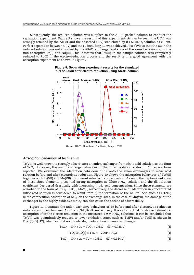
SEPARATION BEHAVIOUR OF SOME FISSION PRODUCTS WITH ELECTROCHEMICAL/ANION EXCHANGE METHOD
8 ACTINIDE AND FISSION PRODUCT PARTITIONING AND TRANSMUTATION – © OECD/NEA 2010
Subsequently, the reduced solution was supplied to the AR-01 packed column to conduct the separation experiment. Figure 9 shows the results of this experiment. As can be seen, the U(IV) was strongly retained by the AR-01 and the adsorbed U(IV) was eluted by 0.1 M HNO3 solution as eluent. Perfect separation between U(IV) and the FP including Ru was achieved. It is obvious that the Ru in the reduced solution was not adsorbed by the AR-01 exchanger and showed the same behaviour with the non-adsorptive Sr(II) and Nd(III). This indicates that Ru(III) in the sample solution was completely reduced to Ru(II) in the electro-reduction process and the result is in a good agreement with the adsorption experiment as shown in Figure 7.
Figure 9: Separation experiment results for the simulated fuel solution after electro-reduction using AR-01 column
Resin: AR-01, Flow Rate: 5cm3/ min, Temp.: 25oC
0
1
2
3
4
5
0
20
40
60
80
100
120
0 20 40 60 80 100 120 140 160
SrZrRuNdU
FP c
once
ntra
tion
/ mm
ol/d
m3
U c
once
ntra
tion
/ mm
ol/d
m3
Effluent volume / cm 3
Deadvolume 6mol/dm 3-HNO 3 0.1mol/dm 3-HNO 3
U(IV) purity:>99%
0
1
2
3
4
5
0
20
40
60
80
100
120
0 20 40 60 80 100 120 140 160
SrZrRuNdU
FP c
once
ntra
tion
/ mm
ol/d
m3
U c
once
ntra
tion
/ mm
ol/d
m3
Effluent volume / cm 3
Deadvolume 6mol/dm 3-HNO 3 0.1mol/dm 3-HNO 3
U(IV) purity:>99%
Feed
Adsorption behaviour of technetium Tc(VII) is well known to strongly adsorb onto an anion exchanger from nitric acid solution as the form of TcO4
–. However, the anion exchange behaviour of the other oxidation states of Tc has not been reported. We examined the adsorption behaviour of Tc onto the anion exchangers in nitric acid solution before and after electrolytic reduction. Figure 10 shows the adsorption behaviour of Tc(VII) together with Re(VII) and Mn(VII) in different nitric acid concentration. As seen, the hepta-valent state of these three elements presented strong adsorption at dilute HNO3 solution and the distribution coefficient decreased drastically with increasing nitric acid concentration. Since these elements are adsorbed in the form of TcO4
–, ReO4–, MnO4
–, respectively, the decrease of adsorption in concentrated nitric acid solution is considered to result from: i) the formation of the neutral acid such as HTcO4; ii) the competition adsorption of NO3
– on the exchange sites. In the case of Mn(VII), the damage of the exchanger by the highly oxidative MnO4
– can also cause the decline of adsorbability.
Figure 11 illustrates the anion exchange behaviour of Tc before and after electrolytic reduction onto two anion exchangers, AR-01 and SiPyR-N4, respectively. It was found that Tc showed almost no adsorption after the electro-reduction in the measured 1-9 M HNO3 solutions. It can be concluded that Tc(VII) was quantitatively reduced to lower oxidation states such as Tc(IV) and/or Tc(II) as shown in Eqs. (3)-(5) [12], which exhibit no or only slight adsorption on anion exchanger.
TcO4– + 4H+ + 3e = TcO2 + 2H2O (E0 = 0.738 V) (3)
TcO2⋅2H2O(s) = TcO2+ + 2OH– + H2O (4)
TcO2 + 4H+ + 2e = Tc2+ + 2H2O (E0 = 0.144 V) (5)

SEPARATION BEHAVIOUR OF SOME FISSION PRODUCTS WITH ELECTROCHEMICAL/ANION EXCHANGE METHOD
ACTINIDE AND FISSION PRODUCT PARTITIONING AND TRANSMUTATION – © OECD/NEA 2010 9
Figure 10: Adsorption of Mn(VII), Tc(VII) and Re(VII) from nitric acid solution onto AR-01
1086420100
101
102
103
104
105
106
HNO3 concentration (mol/dm3)
Dis
trib
utio
n co
effic
ient
(dm
3 /kg)
Mn(VII)Tc(VII)Re(VII)
Metals Conc. 10 mmol/dm3
Temp. 333 K
Figure 11: Adsorption behaviour of Tc in nitric acid solution before and after electro-reduction (298 K)
100
101
102
103
0 2 4 6 8 10
AR-01/BEAR-01/AE
SiPyR-N4/BESiPyR-N4/AE
Dis
trib
utio
n co
effic
ient
(dm
3 /kg)
HNO3 concentration (mol/dm3)BE: before electro-reduction AE: after electro-reduction
Conclusions
• Ru(III) showed fairly strong adsorption onto anion exchanger as nitrosylnitrato-complexes such as RuNO(NO3)4
– and RuNO(NO3)52–, which are formed in concentrated nitric acid solution.
The separation between U(VI) and Ru(III) was not sufficient in the separation experiment using the column packed with AR-01 anion exchanger.
• Ru(III) could be effectively reduced to a lower oxidation state probably Ru(II) in the electro-reduction process using the flow type electrolysis cell. Ru(II) presented no or very weak adsorption onto anion exchanger. In the separation experiment using anion exchange column, a complete separation of Ru(II) from U(IV) was achieved.
• Tc(VII) was strongly adsorbed by anion exchanger as the form of TcO4–. In electro-reduction,
Tc(VII) was quantitatively reduced to its lower oxidation states such as Tc(IV) and/or Tc(II), which exhibited no or only slight adsorption on anion exchanger.

SEPARATION BEHAVIOUR OF SOME FISSION PRODUCTS WITH ELECTROCHEMICAL/ANION EXCHANGE METHOD
10 ACTINIDE AND FISSION PRODUCT PARTITIONING AND TRANSMUTATION – © OECD/NEA 2010
References
[1] Wei, Y-Z., T. Arai, M. Kumagai, A. Bruggeman, Proc. GLOBAL 2003, New Orleans, LA, USA, 16-20 November 2003, 479-484.
[2] Wei, Y-Z., T. Arai, H. Hoshi, M. Kumagai, Proc. GLOBAL 2005, Tsukuba, Japan, 9-13 October 2005, Paper-032.
[3] Ichikawa, F., S. Uruno, H. Imai, Bull. Chem. Soc. Jpn., 34, 952 (1961).
[4] Faris, J.P., R.F. Buchanan, Anal. Chem., 36, 1157 (1964).
[5] Wei, Y-Z., M. Kumagai, et al., Ion Exchange Developments and Applications, J.A. Greig (Ed.), SCI, London, p. 174 (1996).
[6] Marsh, S.F., “Ion Exchange Advances”, Proc. IEX’92, SCI, London, p. 358 (1992).
[7] Nogami, M., Y. Fujii, T. Sugo, J. Radioanal. Nucl. Chem., 203, 109 (1996).
[8] Iwasa, S., T. Arai, Wei, Y-Z., M. Kumagai, K. Murata, K. Takeda, J. Ion Exchange, 12, 40 (2001) (in Japanese).
[9] Diana, J-J., Report CEA-R-4813, Fontenay-aux-Roses Nuclear Research Centre (1977).
[10] Wei Y-Z., M. Kumagai, Y. Takashima, et al., J. Nucl. Sci. Technol., 35, 357 (1998).
[11] Zhang, A., Wei, Y-Z., T. Arai, M. Kumagai, Solvent Extr. Ion Exch., 24 (3), 447-462 (2006).
[12] Hoshi, H., Wei, Y-Z., M. Kumagai, T. Asakura, Y. Morita, J. Radioanal. Nucl. Chem., 262 (3), 601-605 (2004).

DEVELOPMENT OF N,N-DI-ALKYLAMIDES FOR U(VI) SELECTIVE SEPARATION
ACTINIDE AND FISSION PRODUCT PARTITIONING AND TRANSMUTATION – © OECD/NEA 2010 1
Development of N,N-di-alkylamides for U(VI) selective separation
Shinichi Suzuki, Tsuyoshi Yaita, Yumi Sugo, Takaumi Kimura Japan Atomic Energy Agency, Japan
Abstract For the development U(VI) selective separation process in the LWR and FBR spent fuel treatments, new N,N-dialkylamides; N,N-dihexyl-(2-ethyl)butanamide (DH2EBA), N,N-dioctyl-(2-ethyl) butanamide (DO2EBA), N,N-dihexyl-(2,2-dimethyl)propanamide (DHDMPA) and N,N-dioctyl-(2,2-dimethyl) propanamide (DODMPA) are synthesised, and extraction behaviour of U(VI), Pu(IV), Np(VI), Np(IV) and simulated fission products by these compounds are investigated. DO2EBA, DH2EBA, DHDMPA and DODMPA can recover U(VI) selectively without accumulating Pu(IV) in uranium selective separation process. In this paper, results of extraction property of U(VI), Pu(IV) and simulated FP, extraction of macro amount of U(VI) by N,N-dialkylamides, and gamma-ray radiolysis of N,N-dialkylamides will be summarised.

DEVELOPMENT OF N,N-DI-ALKYLAMIDES FOR U(VI) SELECTIVE SEPARATION
2 ACTINIDE AND FISSION PRODUCT PARTITIONING AND TRANSMUTATION – © OECD/NEA 2010
Introduction
In our laboratory, N,N-dialkylamides have been developed as extractant based on solvent extraction technique for nuclear spent fuel treatment at L-F transition periods (from LWR to FR).
N,N-dialkylamides were developed as one of the alternative extractant of tri-butyl phosphate (TBP) [1-8]. Extraction behaviour of U(VI) and Pu(IV) with N,N-dialkylamides were almost similar to those with TBP.
N,N-dialkylamides also have some advantages, namely, their complete incinerability (CHON principle) and high stability for hydrolysis and radiolysis. Their main degradation products are carboxylic acids and secondary amines which hardly affect the separation of U(VI) and Pu(IV) from fission products. Further, the synthesis of N,N-dialkylamides was relatively easy with reaction of carboxylic chloride and secondary amine.
The main purpose of N,N-dialkylamides development is selective separation of uranium(VI) with branched N,N-dialkylamides and group separation of Pu-Np linear alkyl type N,N-dialkylamide (N,N-dioctylhexanamide: DOHA) for spent fuel treatment. As the branched alkyl type N,N-dialkylamides have the steric hindrance on complexation with metal cations, branched alkyl type N,N-dialkylamides can be used to separate An(VI) from An(IV). On the other hand, linear type N,N-dialkylamides have potential for alternative extractant for tri-butyl phosphate (TBP) because linear type N,N-dialkylamide can extract An(VI) and An(IV). In our previous research work, we have proposed N,N-di(2-ethl)hexyl-(2,2-dimethyl)propanamide (D2EHDMPA) as a candidate extractant for uranium selective separation in FBR spent fuel treatments. However D2EHDMPA showed poor U(VI) loading capacity in organic phase [9].
For the purpose of improvement of U(VI) loading capacity in organic phase, four kinds of new N,N-di-alkylamides: N,N-dihexyl-(2,2-dimethyl)propanamide (DHDMPA), N,N-dioctyl-(2,2-dimethyl) propanamide (DODMPA), N,N-dioctyl-(2-ethyl)butanamide(DO2EBA), N,N-dihexyl-(2-ethyl)butanamide (DH2EBA) are synthesised.
In this paper, our experimental results of new N,N-dialkylamides extraction property of U(VI)/Pu(IV), extraction of macro amount of U(VI), and gamma-ray radiolysis will be summarised.
Experimental
The structures of used new N,N-dialkylamides are shown in Figure 1. These new N,N-dialkylamides: N,N-dihexyl-(2,2-dimethyl)propanamide (DHDMPA), N,N-dioctyl-(2,2-dimethyl)propanamide (DODMPA), N,N-dioctyl-(2-ethyl)butanamide (DO2EBA), N,N-dihexyl-(2-ethyl)butanamide (DH2EBA), were synthesised in our laboratory. The synthetic method in the literature was used to all runs [10-11]. The organic samples obtained were purified by distillation under vacuum. N,N-di-alkylamides were identified by NMR (INOVA plus 400 MHz, VARIAN), FT-IR (FTS-135, BIO-RAD), Liquid Chromatography (LC-7100, HITACHI) and gas chromatography (G-6000, HITACHI). The N,N-dialkylamides’ high degree of purity was confirmed by the gas chromatography. Other chemicals were in analytical grade and used as received. The radioactive tracers of 233U and 238Pu were obtained from Sceti Company Ltd. In the macro amount of uranium extraction, U3O8 standard of JAERI-U1-No5 (purity: 99.9%) was used.
Equal volumes of aqueous and pre-equilibrated organic phases containing U(VI) and Pu(IV) were shaken for 10 minutes in a thermostatic atmosphere at 298 K within ±0.1 K. After the equilibration, the system was centrifuged for 5 minutes. The concentrations of metal ions used in the extraction were 8.4 × 10⁻⁷ mol/dm3 for U(VI) and 4.2 × 10⁻¹² mol/dm3 for Pu(IV), respectively.
Distribution coefficients (DU(VI) and DPu(IV)) of U(VI) and Pu(IV) between N,N-di-alkylamides in dodecane and nitric acid solution were determined by measurements of their activities in both phases. Their alpha activities were measured by using liquid scintillation counter (Tri-CARB 2700TR/AB, Packard) with 5 ml of scintisol EX-H cocktail.
For extraction with macro amounts U(VI), aqueous phase of 238.7 g/dm3-3.1 mol/dm3 HNO3, and organic phase of 1.0 mol/dm3 N,N-di-alkylamides in dodecane were treated in a similar manner as above. U(VI) concentration and nitric acid concentration both of aqueous and organic phases were determined by NaOH titration with automatic potentiometric titrator (AT-510, Kyoto Electronics).

DEVELOPMENT OF N,N-DI-ALKYLAMIDES FOR U(VI) SELECTIVE SEPARATION
ACTINIDE AND FISSION PRODUCT PARTITIONING AND TRANSMUTATION – © OECD/NEA 2010 3
Figure 1: Structure of N,N-dialkylamides
The gamma-ray irradiation was performed at 60Co gamma-ray irradiation facility in JAEA Takasaki. The sample for irradiation was used five kinds of 1.0 mol/dm3 N,N-di-alkylamides-dodecane solution and 30 v/v% tri-butyl phosphate-dodecane. The maximum dose absorbed by the solvent was about 1 MGy. The gamma-ray irradiated samples were analysed by GC-MS (GCMS-QP2010Plus, SHIMADZU).
Results
The distribution ratio of U(VI):DU(VI) and Pu(IV):DPu(IV) obtained are summarised in Table 1. In the comparative study of distribution ratio U(VI) and Pu(IV) with these four kinds of N,N-di-alkylamides, these branched alkyl group also have potential of U(VI) separation from Pu(IV). The values of separation factor (DU(VI)/DPu(IV)) of branched alkyl group were more than 10. The DU(VI) values and DPu(IV) values between 1.0 mol/dm3 DO2EBA in n-dodecane and various nitric acid solutions are shown in Figure 1. The DU(VI) and DPu(IV) values by DO2EBAwith branching carbonyl alkyl chain are larger than those by D2EHDMPA with branching carbonyl alkyl chain and nitrogen alkyl chain, respectively. This difference of D values are attributed to alkyl chain branching position of R1 or R2 and branching alkyl chain structure in N,N-dialkylamide, R1C(O)N(R2)2. U(VI) and Pu(IV) co-ordinate to D2EHDMPA or DO2EBA on the position of carbonyl oxygen atom. Branching alkyl chain structure on carbonyl group of D2EHDMPA is more bulky for metal co-ordination than that of DO2EBA.
Table 1: Summary of distribution ratio of U(VI) and Pu(IV) by 1.0 mol/dm3 N,N-dialkylamides-n-dodecane from 3.0 M HNO3
N,N-dialkylamides DU(VI) DPu(VI) N,N-dihexyl-(2-ethyl)butanamide 5.91 <0.56 N,N-dioctyl-(2-ethyl)hexanamide 4.81 <0.01 N,N-dihexyl-(2,2-methyl)propanamide 2.98 <0.01 N,N-dioctyl-(2,2-methyl)propanamide 2.50 <0.01
In our previous research work on extraction of U(VI) and Pu(IV) by linear alkyl type N,N-di-alkylamide, the DU(VI) value was as same as the DPu(IV) value [12]. However, for the extraction by D2EHDMPA and DO2EBA, the DPu(IV) value is smaller than the DU(VI) value. Such behaviour as Pu(IV) can be explained on the basis of increased steric hindrance caused by bulky amide molecules around Pu(IV) that is already co-ordinated with nitrate anions. Owing to this steric hindrance, DO2EBA is able
CN
O
CN
O
CN
O
DH2EBA DO2EBA DHDMPA
CN
O
CN
O
CN
O
DODMPA D2EHDMPA DOHA

DEVELOPMENT OF N,N-DI-ALKYLAMIDES FOR U(VI) SELECTIVE SEPARATION
4 ACTINIDE AND FISSION PRODUCT PARTITIONING AND TRANSMUTATION – © OECD/NEA 2010
to separate U(VI) from Pu(IV) like D2EHDMPA without chemical reduction from Pu(IV) to Pu(III) like the Purex process. Furthermore, selective separation of U(VI) by DO2EBA enables reduction of reduction processes from Pu(IV) to Pu(III), and exclusion of the side reaction by reducing chemicals like hydroxyl amine(HAN) and hydrazine.
In considering new compound for reprocessing process, lording of U(VI) in organic phase is important key point. In our previous work, D2EHDMPA gave good separation of U(VI) from Pu(IV) and poor extractability for macro amount of U(VI). In this study, extractability for macro amount of U(VI) with new N,N-di-alkylamides was evaluated for process adoption. Especially, the aim of our study is U(VI) selective separation from nuclear spent fuels.
Table 2 shows macro amount of U(VI) extraction results using 1.0 mol/dm3 N,N-dialkylamides-dodecane system. From the extraction results using 238.7 g/dm3 U(VI)-3.0 mol/dm3 aqueous solution, DO2EBA and DH2EBA can extract more than 100 g/dm3 uranium(VI) for organic phase. In this case, uranium concentration in organic phase was 108.2 g/dm3 for DO2EBA and 123.2 g/dm3 for DH2EBA, respectively. In addition, DO2EBA extracted 121 g/dm3 U(VI) without making the third phase from 269.0g/dm3 U(VI)-3.5 mol/dm3 HNO3 aqueous solution. While DH2EBA made the third phase in aqueous condition of 269.0g/dm3 U(VI)-3.5mol/dm3 HNO3. To introduce DO2EBA for nuclear spent fuel reprocessing, we will try to evaluate the third phase formation boundary of U(VI)-HNO3-DO2EBA-dodecane system.
Table 2: Uranium(VI) concentration in organic phase by 1.0 mol/dm3 N,N-dialkylamides-n-dodecane system
Aqueous condition: 238.7 g/dm3 U(VI) – 3.1 mol/dm3 HNO3
N,N-dialkylamides U(VI) concentration in organic phase N,N-di-(2-ehtl)hexyl-(2,2-dimethyl)propanamide 066.7 g/dm3 N,N-di-hexyl-(2-ethyl)butanamide (DH2EBA) 123.2 g/dm3 N,N-di-octyl-(2-ethyl)hexanamide (DO2EBA) 108.2 g/dm3
When the new compounds were adapted for nuclear spent fuel reprocessing, the stability (hydrolysis and radiolysis) of new compounds were also key point. Especially, FBR spent fuels has the higher irradiation dose than LWR spent fuels. In this study, the gamma-ray irradiation using 60Co for five kinds N,N-dialkylamides and TBP were carried out. The maximum absorbed dose was estimated about 1 MGy.
Figure 2 shows radiation stability of N,N-dialkylamides (DOHA, DH2EBA, DO2EBA, DHDMPA and DODMPA) against radiation dose. In comparison of stability of N,N-dialkylamides in gamma irradiation, i.e. comparison of hexyl group (DH2EBA and DHDMPA) and octyl group (DO2EBA and DODMPA), the hexyl group was more stable than the octyl group. Furthermore, the resistance for gamma irradiation of carbonyl alkyl branching of N,N-dialkylamides (DOHA, DO2EBA and DODMPA) was investigated. As a result of gamma irradiation, the resistance over the radiation of DOHA, DO2EBA and DODMPA was the following order, DHOA > DO2EBA > DODMPA.
Gasparini investigated radiolysis of tertiary amine, N,N-dialkylamide and TBP [4] and mentioned the absorbed dose by the solvent was estimated about 5 kGy in the first extraction cycle in reprocessing of FBR spent fuels. The maximum absorbed dose of about 1 MGy used our research work was large excessive dose for judging from his report. It judged from his report, the degradation of N,N-dialkylamides with 5 kGy was equal to the degradation of TBP.
Conclusions
Solvent extraction of U(VI) and Pu (IV) by four kinds of new N,N-dialkylamides, high concentrated U(VI) extraction and radiolysis of four compounds were carried out and the following results were obtained:
• Branched alkyl group combined new N,N-dialkylamides (DH2BEA, DO2EBA, DHDMPA and DODMPA) show good separation factors for U/Pu.
• DH2EBA and DO2EBA show enough extraction ability for the macro amount of U(VI).

DEVELOPMENT OF N,N-DI-ALKYLAMIDES FOR U(VI) SELECTIVE SEPARATION
ACTINIDE AND FISSION PRODUCT PARTITIONING AND TRANSMUTATION – © OECD/NEA 2010 5
• The radiation stability of N,N-dialkylamides (DOHA, DH2EBA, DO2EBA, DHDMPA and DODMPA) was less than that of TBP.
• For adoption of N,N-dialkylamides for L-F transition periods, more information of degradation, extraction of fission products and accurate of the third phase formation boundary are necessary.
Figure 2: Radiolysis of different compounds using 60Co gamma-ray irradiation
1.0 ml/dm3 amide-dodecane for DOHA, DHDMBA and D2EH2EBA, 30% TBP-dodecane
0
20
40
60
80
100
0 200 400 600 800 1,000
1.0 M DOHA1.0 M DH2EBA1.0 M DO2EBA1.0 M DHDMPA1.0 M DODMPA1.0 M TBP
Deg
rada
tion
(%)
Dose[kGy]
Acknowledgements The present study includes the results of “Development of New N,N-di-alkylamides for FBR spent fuel reprocessing” entrusted to the Japan Atomic Energy Agency by the Ministry of Education, Culture, Sports, Science and Technology of Japan (MEXT).
References
[1] Siddall, T.H. III, J. Phys. Chem., 64, 1863 (1960).
[2] Siddall, T.H. III, DP-541 (1961).
[3] Gasparini, G.M., G. Grossi, Sep. Sci. Technol., 15, 825 (1980).
[4] Gasparini, G.M., G. Grossi, Solv. Extr. Ion. Exch., 4, 1233 (1986).
[5] Musikas, C., Sep. Sci. Technol., 23, 1211 (1988).
[6] Musikas, C., N. Condamine, C. Cuillerdier, Anal. Sci., 7, 11 (1991).
[7] Condamine, N., C. Musikas, Solv. Extr. Ion. Exch., 10, 69 (1992).
[8] Thiollet, G., C. Musikas, Solv. Extr. Ion. Exch.,7 (5), 813 (1989).

DEVELOPMENT OF N,N-DI-ALKYLAMIDES FOR U(VI) SELECTIVE SEPARATION
6 ACTINIDE AND FISSION PRODUCT PARTITIONING AND TRANSMUTATION – © OECD/NEA 2010
[9] Susuki, S., Y. Sasaki, T. Yaita, T. Kimura, Proceedings of International Conference ATALANTE2004 Advances for Nuclear Fuel Cycle, Nîmes, France, 21-24 June 2004, P1-63.
[10] Wagner, R.B., H.D. Zook, Synthetic Organic Chemistry, J. Wiley and Sons, Hoboken, New Jersey (1965), p. 566.
[11] Starks, C.M., C. Liotta, Phase Transfer Catalysis. Principles and Techniques, Academic Press, New York (1978).
[12] Tachimori, S., S. Suzuki, S. Sasaki, J. Nucl. Sci. Tech., 43, 1235 (2001) (in Japanese).

Am(III)/Eu(III) SEPARATION WITH HYDROPHOBIC ALKYLATED TPEN
ACTINIDE AND FISSION PRODUCT PARTITIONING AND TRANSMUTATION – © OECD/NEA 2010 1
Am(III)/Eu(III) separation with hydrophobic alkylated TPEN
Tatsuro Matsumura Japan Atomic Energy Agency, Japan
Kenji Takeshita Chemical Resources Laboratory, Tokyo Institute of Technology, Japan
Yusuke Inaba, Atsunori Mori Graduate school of Engineering, Kobe University, Japan
Abstract We are developing a new MA/Ln separation process with TPEN (N,N,N’,N’-tetrakis(2-pyridylmethyl)-ethylenediamine) and its derivatives for P&T technology of HLLW from spent nuclear fuel reprocessing plants. TPEN is a hexadentate soft-donor ligand that has six soft-donor sites as a kind of podand type molecule and can encapsulate a metal ion. TPEN has good selectivity of Am(III) from Ln(III) and has potential to establish partitioning of MA. We elucidated extraction behaviour of Am(III) and Eu(III) using several organic solvents and found that the maximum SFAm/Eu was over 250.
From the viewpoint of practical application, the hydrophobicity of TPEN must be improved. Because the dissolution of a slight amount of TPEN (about 10–4 mol/l) to water will restrict decontamination of Ln in extraction process. In this study, the hydrophobicity of TPEN was improved by introducing alkyl groups and the effect of the introduction of alkyl groups on the separation of Am(III) and Eu(III) was examined. We synthesised various types of derivatives of TPEN. A series of the derivatives, N,N,N’,N’-tetrakis((5-alkoxypyridin-2-yl)-methyl)ethylene-diamine, TRPEN, showed good selectivity. One of them, N,N,N’,N’-tetrakis((5-dodecyloxypyridin-2-yl)-methyl)ethylenediamine, TDdPEN has excellent performance of Am/Eu separation. The maximum separation factor, SFAm/Eu, was over 800 at pH 4.50, and significant separation factor at pH 2.0. The hydrophobicity of TRPEN is checked by the distribution data between water and chloroform, and improved successfully. The approach for development of hydrophobic derivatives of TPEN was effective. The hydrophobic alkylated TPEN, TRPEN, is applicable to the separation process of An(III) from Ln(III). This paper describes the synthesis of the hydrophobic alkylated TPEN and the Am/Eu separation performance of the ligands by the batch experiments.

Am(III)/Eu(III) SEPARATION WITH HYDROPHOBIC ALKYLATED TPEN
2 ACTINIDE AND FISSION PRODUCT PARTITIONING AND TRANSMUTATION – © OECD/NEA 2010
Introduction
Reduction of radioactive toxicity of HLW is very important to decrease the risk of the environmental impact of nuclear wastes disposed to deep underground. If long-lived minor actinides (MA) are removed from HLW before the final disposal and MA convert to short-lived nuclides by transmutation technology, the environmental load of HLW will be reduced largely. However, lanthanides, whose total amount corresponds to up to 30 times that of MA in HLW [1], adversely affects the efficiency of the transmutation of MA, because these elements absorb a large proportion of neutron. Therefore, the separation of MA from lanthanides is one of essential subjects to establish transmutation technology.
It is well known that separating trivalent actinides [An(III)] and lanthanides [Ln(III)] is one of the most challenging issues, because of their similarity of chemical properties. One rational approach for the separation of An(III) is to use a soft-donor extractant based on its preferable co-ordination to softer An(III). Nitrogen-based soft-donor extractants have been attracted attention as a means of establishing a new sustainable separation process which has the feature of organic solvent waste free based on the combustibility of the extractant [2]. As a result, considerable efforts have been devoted to the development of new nitrogen-donor extractants for separating An(III) from Ln(III) [3]. Jensen, et al. reported that TPEN demonstrates 100-fold preference for Am(III) over Ln(III) from the difference between stability constants in the aqueous phase [4]. TPEN is a hexadentate ligand and can encapsulate a metal ion. We have reported that Am(III) was selectively extracted from the aqueous phase containing Ln(III) by TPEN in organic phase [5,6]. TPEN has potential to establish partitioning of minor actinides; however, the hydrophobicity should be improved. Recently, we succeed to synthesise several hydrophobic derivatives of TPEN.
Improvement of hydrophobicity of water-soluble nitrogen-donor ligand was reported [7]. As the analogue of the molecules, expected structures of hydrophobic derivatives of TPEN were shown in Figure 1. Type (a), TPDREN, has hydrophobic alkyl groups connected with the molecular framework (N-C-C-N structure) in TPEN molecule, and type (b), TRPEN, has the alkyl groups connected with pyridyl groups. Previously, we reported that the derivatives of type (a) [8]. In this work, we synthesised new derivatives of type (b), and examined both the extractability and selectivity of Am(III) and Eu(III).
Figure 1: Candidate molecular structure of hydrophobic derivatives of TPEN
NN
N
NN
N
NN
N
NN
N
TPEN
NN
N
NN
N
NN
N
NN
N
R
R
a) b)
NN
N
NN
NR
R
RR
NN
N
NN
N
NN
N
NN
N
TPEN
NN
N
NN
N
NN
N
NN
N
R
RNN
N
NN
N
NN
N
NN
N
R
R
a) b)
NN
N
NN
NR
R
RR
NN
N
NN
NR
R
RR
Experimental
Synthesis of the hydrophobic derivatives of TPEN Figure 2 shows the chemical structures of the synthesised TRPEN. The synthetic routes of the TRPEN were considered by referring to the paper on the synthesis of TPEN analogues [9,10]. The synthetic reaction was shown in Figure 3. 4-(2-alkoxy)-2-chloromethylpyridine was prepared and reacted with 1,2-ethylenediamine.

Am(III)/Eu(III) SEPARATION WITH HYDROPHOBIC ALKYLATED TPEN
ACTINIDE AND FISSION PRODUCT PARTITIONING AND TRANSMUTATION – © OECD/NEA 2010 3
Figure 2: Chemical structure of synthesised derivatives, TRPEN
N NN
NN
N
OO
OO
N NN
NN
N
OO
OO
N NN
NN
N
OO
OO
N NN
NN
N
OO
OO
TBPEN(N,N,N’,N’-tetrakis((5-butoxypyridin-2-yl)
methyl)ethylenediamine
TEHPEN(N,N,N’,N’-tetrakis((5-ethylhexyloxypyridin-2-yl)
methyl)ethylenediamine
TOPEN(N,N,N’,N’-tetrakis((5-octyloxypyridin-2-yl)
methyl)ethylenediamine
TDdPEN(N,N,N’,N’-tetrakis((5-dodecyloxypyridin-2-yl)
methyl)ethylenediamine
N NN
NN
N
OO
OO
N NN
NN
N
OO
OO
N NN
NN
N
OO
OO
N NN
NN
N
OO
OO
TBPEN(N,N,N’,N’-tetrakis((5-butoxypyridin-2-yl)
methyl)ethylenediamine
TEHPEN(N,N,N’,N’-tetrakis((5-ethylhexyloxypyridin-2-yl)
methyl)ethylenediamine
TOPEN(N,N,N’,N’-tetrakis((5-octyloxypyridin-2-yl)
methyl)ethylenediamine
TDdPEN(N,N,N’,N’-tetrakis((5-dodecyloxypyridin-2-yl)
methyl)ethylenediamine
Figure 3: Synthesis of TRPEN
1,2-ethylenediamine
4・ +
4-(2-alkoxy)-2-chloromethylpyridine
+4HCl
N,N,N’,N’-tetrakis((5-alkoxypyridin-2-yl)-methyl)ethylenediamine.
(TRPEN)
NH2NH2
N
ClOR
N NN
NN
NO
RO
R
O
RO
R1,2-ethylenediamine
4・ +
4-(2-alkoxy)-2-chloromethylpyridine
+4HCl
N,N,N’,N’-tetrakis((5-alkoxypyridin-2-yl)-methyl)ethylenediamine.
(TRPEN)
NH2NH2
N
ClOR
N NN
NN
NO
RO
R
O
RO
R
Extraction of Am(III) and Eu(III) All reagents used in the extraction experiments were reagent grade and were used without further purification. The radiotracers supplied from FRAMATOME, 241Am (800 kBq in 1 mL 1 M HCl) and 152Eu (3.0 MBq in 5 mL 1 M HCl), were dried under an infrared lamp and diluted by 10–3 M HNO3.
TBPEN was insoluble in non-polar organic solvents, such as dodecane, but dissolved in polar solvents, such as nitrobenzene, alcohol and chloroform. On the other hand, TEHPEN, TOPEN and TDdPEN were dissolved in dodecane, but the solutions were cloudy. In this study, nitrobenzene was used as diluent of organic phase. In a glass centrifugal tube with stopper, 2.5 mL of aqueous solution and 2.5 mL of organic phase were contacted for 30 minutes with the aid of a shaker at 25±0.5°C for pre-equilibrium of pH. The resulting mixture was centrifuged at 2 500 rpm for 5 min. The pH value of the aqueous phase was measured by a pH meter (F-23, Horiba) and adjusted to an aimed pH value by aqueous ammonia or nitric acid. After the pre-equilibrium of pH, 241Am and 152Eu stock solutions were added and the tubes were shaken vigorously at 25±0.5°C for 90 min. The resulting mixtures were then centrifuged at 2 500 rpm for 15 min. After centrifuging, an aliquot of 1.0 mL was sampled from both

Am(III)/Eu(III) SEPARATION WITH HYDROPHOBIC ALKYLATED TPEN
4 ACTINIDE AND FISSION PRODUCT PARTITIONING AND TRANSMUTATION – © OECD/NEA 2010
phases. The radioactivities of 241Am and 152Eu in the aqueous and organic phases were analysed by a high-purity germanium gamma-spectrometer system (EG&G Ortec Ltd.). The distribution ratio, DM, and the separation factor, SFAm/Eu, were evaluated as:
[ ][ ]phaseaqueoustheinMofionconcentrat
phaseorganictheinMofionconcentratDM = (M = Am, Eu) (1)
EuAmEuAm DDSF = (2)
Results and discussion
The results of extraction experiments of Am(III) and Eu(III) with the TPEN derivatives are summarised in Figure 4. The distribution ratios of Am(III) and Eu(III) and selectivity of Am(III) by TPEN were effective values from pH 4.3 to 6.0. However, no extractability was observed at pH 3.0 [10]. On the other hand, TBPEN was observed significant selectivity of Am(III) from Eu(III) in the pH range from 2.0 to 6.0. The maximum SFAm/Eu was obtained as 91 at pH 3.02. It should be noted that maximum value of SFAm/Eu was obtained at pH 3.02 and valuable separation factor, SFAm/Eu, 6.3, was obtained at pH 1.90. This indicates that TBPEN and other derivatives, TRPEN, are applicable to separation process of An(III) from Ln(III) without using buffer. TDdPEN, which has dodecyloxy groups connected to pyridyl groups, has high selectivity of Am(III) from Eu(III) between pH 4.0 to 5.0. The maximum SFAm/Eu was 820 at pH 4.5. The selectivity of Am(III) by TDdPEN is higher than BTP [11].
The nitrogen-donor ligands, such as TRPEN, are generally classified to neutral extractants. Therefore, Am(III) and Eu(III) are supposed to be extracted into the organic phase as M(TRPEN)(NO3)3 (M = Am or Eu) according to an ion-pair extraction mechanism:
M3+ (a) + 3NO3 (a) + TRPEN (o) ↔ M(TRPEN)(NO3)3 (o) (M = Am, Eu) (3)
Eq. (3) indicates that pH in the aqueous phase is not affected directly to the metal extraction. Thus, the results of Figure 3 suggest that side reactions such as protonation of TRPEN and hydrolysis of these trivalent ions play important roles to determine the separation factor of Am(III). However, the detailed extraction mechanism should be further investigated and the role of TRPEN in the extraction process should be made clear for the development of extraction system with TRPEN and the molecular design of other high-performance TPEN derivatives classified to type (b).
Conclusion
We succeed to synthesise high performance hydrophobic derivatives of TPEN, N,N,N’,N’-tetrakis((5-alkoxypyridin-2-yl) methyl)ethylenediamine (TRPEN), which has application potential to the separation process of An(III) from Ln(III). One of them, N,N,N’,N’-tetrakis((5-dodecyl-oxypyridin-2-yl)methyl) ethylenediamine, TDdPEN, has extremely high selectivity of Am(III) from Eu(III). The maximum SFAm/Eu of over 800 was obtained in the extraction system using nitrobenzene as a diluent. The improvement of hydrophobicity of TPEN molecule, in which n-alkyloxy groups are connected to the pyridyl groups of TPEN is effective. The technique for the improvement of hydrophobicity of TPEN, which is one of the properties that should be solved to construct MA/Ln separation process, is elucidated.

Am(III)/Eu(III) SEPARATION WITH HYDROPHOBIC ALKYLATED TPEN
ACTINIDE AND FISSION PRODUCT PARTITIONING AND TRANSMUTATION – © OECD/NEA 2010 5
Figure 4: Extraction of Am(III) and Eu(III) (25°C)
a) Organic phase: 1 mM TPEN in nitrobenzene; aqueous phase: 1.0 M NH4NO3 b) Organic phase: 1 mM TBPEN in nitrobenzene; aqueous phase: 1.0 M NH4NO3 c) Organic phase: 1 mM TEHPEN in nitrobenzene; aqueous phase: 1.0 M NH4NO3 d) Organic phase: 1 mM TOPEN in nitrobenzene; aqueous phase: 1.0 M NH4NO3 e) Organic phase: 1 mM TDdPEN in nitrobenzene; aqueous phase: 1.0 M NH4NO3
1.E-04
1.E-03
1.E-02
1.E-01
1.E+00
1.E+01
1.E+02
1.E+03
1.E+04
2.00 3.00 4.00 5.00 6.00
1.E-04
1.E-03
1.E-02
1.E-01
1.E+00
1.E+01
1.E+02
1.E+03
1.E+04
2.00 3.00 4.00 5.00 6.00
1.E-04
1.E-03
1.E-02
1.E-01
1.E+00
1.E+01
1.E+02
1.E+03
1.E+04
2.00 3.00 4.00 5.00 6.00
1.E-04
1.E-03
1.E-02
1.E-01
1.E+00
1.E+01
1.E+02
1.E+03
1.E+04
2.00 3.00 4.00 5.00 6.00
SF=820SF=550
SF=97
DM
SF=36
SF=80
d) TOPEN
b) TBPEN c) TEHPEN
e) TDdPEN
1.E-04
1.E-03
1.E-02
1.E-01
1.E+00
1.E+01
1.E+02
1.E+03
1.E+04
2.00 3.00 4.00 5.00 6.00
a) TPEN
pHeq pHeq pHeq
pHeq pHeq
DM D
M
1.E-04
1.E-03
1.E-02
1.E-01
1.E+00
1.E+01
1.E+02
1.E+03
1.E+04
2.00 3.00 4.00 5.00 6.00
1.E-04
1.E-03
1.E-02
1.E-01
1.E+00
1.E+01
1.E+02
1.E+03
1.E+04
2.00 3.00 4.00 5.00 6.00
1.E-04
1.E-03
1.E-02
1.E-01
1.E+00
1.E+01
1.E+02
1.E+03
1.E+04
2.00 3.00 4.00 5.00 6.00
1.E-04
1.E-03
1.E-02
1.E-01
1.E+00
1.E+01
1.E+02
1.E+03
1.E+04
2.00 3.00 4.00 5.00 6.00
SF=820SF=550
SF=97
DM
SF=36
SF=80
d) TOPEN
b) TBPEN c) TEHPEN
e) TDdPEN
1.E-04
1.E-03
1.E-02
1.E-01
1.E+00
1.E+01
1.E+02
1.E+03
1.E+04
2.00 3.00 4.00 5.00 6.00
a) TPEN
pHeq pHeq pHeq
pHeq pHeq
DM D
M

Am(III)/Eu(III) SEPARATION WITH HYDROPHOBIC ALKYLATED TPEN
6 ACTINIDE AND FISSION PRODUCT PARTITIONING AND TRANSMUTATION – © OECD/NEA 2010
Acknowledgements The authors thank Prof. K.L. Nash, Washington State University for helpful discussion on the complexation of Am(III) and Eu(III) with TPEN.
References
[1] Ando, Y., H. Takano, JAERI-Research 99-004, Japan Atomic Energy Research Institute (1999).
[2] Musikas, C., Inorganic Chimica Acta, 140, 107-206 (1987).
[3] Karmazin, L., M. Mazzanti, C. Gateau, C. Hill, J. Pécaut, Chem. Commun., 23, 2892 (2002).
[4] Jensen, M.P., L.R. Morss, J.V. Beitz, D.D. Ensor, J. Alloys Compounds, 303-304, 137 (2000).
[5] Watanabe, M., R. Mirvaliev, S. Tachimori, K. Takeshita, Y. Nakano, K. Morikawa, R. Mori, Chem. Lett., 31, 1230 (2002).
[6] Matsumura, T., K. Takeshita, “Extraction Separation of americium(III) from europium(III) with TPEN and Decanoic Acid in 1-octanol”, Solv. Extr. Ion Exch., forthcoming.
[7] Cordier, P.Y., C. Hill, P. Baron, C. Madic, M.J. Liljenzin, J. Alloys Compounds, 271-273, 738 (1998).
[8] Matsumura, T., K. Takeshita, Progress in Nuclear Energy, 50, 470-475 (2007).
[9] Sato, M., Y. Mori, T. Iida, Synthesis, 1992, 539.
[10] Matsumura, T., et al., Proceedings of ATALANTE2008, P3-17 (2008).
[11] Geist, A., et al., Actinide and Fission Product Partitioning and Transmutation, 9th Information Exchange Meeting, Nîmes, France, 25-29 September 2006, OECD/NEA, Paris, pp. 708-709 (2007).

THE EFFECTS OF HYDROLYSIS AND RADIOLYSIS ON THE EXTRACTION OF LANTHANIDES AND ACTINIDES
ACTINIDE AND FISSION PRODUCT PARTITIONING AND TRANSMUTATION – © OECD/NEA 2010 1
The effects of hydrolysis and radiolysis on the extraction of lanthanides and actinides with diamides of dipicolinic acid
A. Paulenova,1 B. Drtinova,1,2 J.L. Lapka,1 M.Yu. Alyapyshev,1,3 V.A. Babain,1,3 R.S. Herbst,4 J.D. Law4 1Oregon State University, Corvallis, OR, USA
2Czech Technical University, Prague, Czech Republic 3Khlopin Radium Institute, St. Petersburg, Russia
4Idaho National Laboratory, Idaho Falls, USA
Abstract The hydrolytic and radiolytic stabilities of two (ortho, para) isomers of N,N’-diethyl-N,N’-ditolyl-dipicolinamide (EtTDPA) were investigated. Hydrolysis was performed at various temperatures with 3 M nitric acid and radiolysis with doses up to 130 kGy. Also the synergistic effect of chlorinated dicarbollide (CCD) on extraction with EtTDPA was evaluated. The best Am/Eu separation was found for N,N’-diethyl-N,N’-di(ortho)tolyl-diamide. Acidic hydrolysis at room temperature was not observed and neither hydrolysis nor irradiation with gamma doses of up to 130 kGy caused a significant decrease in separation performance with the studied extraction mixtures.

THE EFFECTS OF HYDROLYSIS AND RADIOLYSIS ON THE EXTRACTION OF LANTHANIDES AND ACTINIDES
2 ACTINIDE AND FISSION PRODUCT PARTITIONING AND TRANSMUTATION – © OECD/NEA 2010
Introduction
In the nuclear waste management industry it is of great importance to understand the effects of radiation on the effectiveness of separation processes. Several widely used extractants such as TBP are known to have degradation products that are undesired [1]. Thus the radiolytic stability of any material to be used in conditions imposed by such an industry requires study before any large scale usage can be utilised.
Within the past two decades, there has been interest to develop soft-donor complexing agents. These are promising extractants for the separation of lanthanides and trivalent actinides and have received significant attention. The separation of these elements is a complex task because the chemistries of these elements are nearly identical, and differ only in a slightly stronger interaction of trivalent actinides with certain ligand donor atoms [2]. A soft donor atom such as nitrogen can covalently co-ordinate the 5f-elements, showing higher selectivity than the harder oxygen atom toward actinide (5f) over lanthanide (4f) elements; therefore, amides are a subject of extensive research as potential extractants of minor actinides from PUREX raffinate.
Current research has led to development of new N-containing reagents and processes with considerable potential for accomplishing the desired separation such as substituted malonic diamides (DIAMEX) [2,3] and tetraalkyl-diglycolamides (TODGA) [4,5]. Previously it was reported that among other substituted diamides of dipicolinic acid, N,N’-diethyl-N,N’-ditolyl-dipicolinamide (Figure 1) shows the best extractability toward americium [6]. A significant synergistic effect was observed in the extraction of trivalent metals by different dipicolinamides (DPA) in the presence of CCD [7], and some diamides of dipicolinic acid were proposed instead of CMPO as components of a modified UNEX solvent [8].
Recently, the results on investigation of extraction of Am and lanthanides (Ln) with different diethyl-ditolyl-diamides of dipicolinic acid as a function of their structure and nitric acid concentration [9] and a synergistic effect of chlorinated cobalt dicarbollide (CCD) on extraction of Am and Ln with diamides [10] were reported. The aim of the present work was to investigate the effect of previous acidic hydrolysis and radiolysis on the extraction performance of ortho and para isomers of the diethyl-ditolyl-diamides of dipicolinic acid and indentify the effect of the methyl group position in tolyl ring on stability, extractability and selectivity of studied EtTDPA toward separation of Am from lanthanides.
Experimental
Extraction procedure Four different organic solvents based on polar solvent FS-13 (trifluoromethyl-phenyl sulfone) were studied: 0.2 M Et(p)TDPA, 0.2 M Et(o)TDPA, and mixtures of 0.02 M CCD with either Et(p)TDPA (0.01 M) or Et(o)TDPA (0.01 M). The FS-13 was obtained from Marshallton Research Laboratories Inc. (King, NC, USA) and used as received. The Cs salt of chloro-protected cobalt bis(dicarbollide), Cs[(8,9,12-Cl3-C2B9H8)2-3-Co]2 (CsCCD) was obtained from Katchem (Rez, Czech Republic) and used as received. Other chemicals were of reagent grade purity and used without any additional purification.
Prior to extraction with 0.2 M EtTDPA, the organic phase was pre-equilibrated with the aqueous phase of an identical composition as in the extraction except the studied metal. A pre-equilibrated organic phase was then contacted with a fresh portion of aqueous phase in the 1:1 organic:aqueous volume ratio, spiked with the radiotracer (152,154Eu or 241Am) and agitated for four minutes which earlier was shown is satisfactory to achieve equilibrium extraction. Initial concentration of Eu was of 10–5 mol/L. Concentration of both metals were measured gamma-spectroscopically with 3” NaI(Tl) well detector. The reported experimental values of distribution ratio are an average from at least two extraction experiments.
For the extraction mixtures, the appropriate amount of the caesium salt CsCCD was dissolved in FS-13, and converted to the acid form (HCCD) by agitation with perchloric acid, followed by a final wash with dilute HNO3 to remove residual perchlorate. The final concentration of HCCD was determined indirectly by potentiometric titration with standard base, assuming a 1:1 ratio of H:CCD in the organic phase. This stock solution was then diluted and used in extraction experiments. The concentration of

THE EFFECTS OF HYDROLYSIS AND RADIOLYSIS ON THE EXTRACTION OF LANTHANIDES AND ACTINIDES
ACTINIDE AND FISSION PRODUCT PARTITIONING AND TRANSMUTATION – © OECD/NEA 2010 3
the extraction mixture prepared for these experiments was 0.02 M HCCD and 0.01 M DPA in FS-13. Extraction of Eu and Am was performed in the identical manner as above.
Hydrolysis and radiolysis For the acidic hydrolytic degradation experiment, the studied organic solvent (pure 0.2 M EtTDPA or the mixture of 0.02 M CCD with 0.01 M EtTDPA in FS-13) was placed into 7 mL plastic vials, layered with 3 M nitric acids, and placed in a thermostated incubator with a horizontal shaker for the desired time and temperature (25, 50 and 70°C). In the end of hydrolysis, the samples were centrifuged and split. The hydrolysed organic phase was investigated using FTIR spectroscopy and then tested for its extraction performance. Equal volumes of the hydrolysed organics and a fresh 3 M nitric acid were spiked with 241Am or 152,154Eu, vigorously agitated for four minutes, split by centrifugation and analysed.
For the radiolytic degradation experiment, the samples of organic solvent, pre-saturated with 3 M nitric acid, were irradiated in sealed glass vials to varying absorbed gamma-ray doses, using the Oregon State University Irradiator (Gammacell, 60Co) providing the centreline dose of 0.59 kGy/hr. The duration of irradiation was varied to achieve the desired absorbed dose (0-130 kGy). A portion of the irradiated organic solutions was then agitated with a fresh portion of 3 M nitric acid solution of equal volume, spiked with Am or Eu for three-minute duration at ambient temperature. In the same manner as above, the samples were centrifuged for two minutes, the phases were split and aliquots of both phases were taken for the metal concentration analysis. The distribution ratios and separation factors of studied metals were determined as the ratio of the appropriate specific activities in the organic and aqueous phases:
Eu
Am
aq
org
DD
SF;]Bq[A
]Bq[AD == (1)
Figure 1: Structures of extractants and solvent: Et(o)TDPA (a), Et(p)TDPA (b), FS-13 (c)
Discussion
Hydrolytic stability It is well known than amides mainly undergo acidic hydrolysis as a result of cleavage of the carbonyl-nitrogen bond [11] after nucleophilic attack by water, thus leaving the carboxylic acid and its complimentary amine. In the case of EtTDPA, the resulting amine is one of the products used during synthesis (N-ethyl-toluidine) and infrared spectra were taken of N-ethyl-toluidine in FS-13 for comparison to hydrolysis samples. The FTIR spectra of the 25°C EtTDPA and EtTDPA+CCD samples showed no discernable changes in their infrared spectra after 100 hours of hydrolysis with 3 M nitric acid for either the ortho or para isomer. This indicates that EtTDPA is hydrolytically stable at these conditions. The 50 and 70°C post-hydrolysis samples revealed only small changes in the spectral features. For example, no changes were observed in the carbonyl absorption wavelengths, while small changes in transmittance were observed in the 1 500-1 550 cm–1 region. However, these changes were not consistent with the spectra obtained for either isomer of N-ethyl-toluidine in FS-13, thus it cannot be confirmed that it was indeed produced by hydrolysis. Despite this, it is evident from this only minor change that even after prolonged hydrolysis both EtTDPA and CCD show significant stability.
S OOCF3
NN
OO
NN
N
OO
N
a) b) c)

THE EFFECTS OF HYDROLYSIS AND RADIOLYSIS ON THE EXTRACTION OF LANTHANIDES AND ACTINIDES
4 ACTINIDE AND FISSION PRODUCT PARTITIONING AND TRANSMUTATION – © OECD/NEA 2010
Radiolytic stability Mowafy [12,13] recently reported that symmetrical diamides are the most stable over unsymmetrical and branched amides. Furthermore, shorter branching substituents on the amide nitrogen led to higher stability as well. EtTDPA has both of these characteristics indicating that some stability against radiation is expected. Analysis of the irradiated EtTDPA and EtTDPA+CCD extraction mixtures shows weakening of the amide nitrogen absorption bands as well as the amide carbonyl stretches. Though some changes were observed no significant degradation was found with the dosage ranges employed in this research.
Previous experiments have shown [14] that a significant extraction of Am and Eu with studied the diamides begins at 3 M nitric acid; therefore, unless otherwise is stated, all extraction experiments were performed from this nitric acid concentration. The post-hydrolysis separation factors for Eu and Am with all four extraction phases are displayed in Table 1. Hydrolysis of 0.2 M EtTDPA in FS-13 with 3 M nitric acid agitated at 25-70°C for several days did not cause a significant decrease of extraction performance, with separation factors varying only slightly over the course of 80 hours. No significant changes in the post-hydrolysis extraction of Am and Eu with the CCD+EtTDPA mixtures were observed except for the D(Am) for 70°C where a sharp maximum for para-EtTDPA was measured as seen in Figure 2(a). Even after a prolonged time of hydrolysis, the D(Am) with “hydrolysed” p-EtTDPA+CCD remains approximately three times higher than with non-hydrolysed p-EtTDPA+CCD.
The dependence of the post-irradiation distribution ratios for Am and Eu with 0.2 M EtTDPA on absorbed dose is shown in Figure 2(b). There was no degradation effect observed for extraction of Eu with the irradiated phase of EtTDPA in FS-13 (pre-saturated with 3 M HNO3 prior to extraction). In contrast, the Am distribution ratios first decrease with the absorbed dose (0-40 kGy) and then remain stable for both irradiated ortho and para isomers of EtTDPA.
Post-irradiation behaviour of the extraction mixtures CCD+EtTDPA in FS-13 is similar to the results obtained from high temperature hydrolysis. While the distribution ratio of both Am and Eu with the ortho-EtTDPA+CCD mixture gradually decrease with increased radiation dose (Figure 4), the distribution ratio of both Am and Eu with the para-EtTDPA+CCD mixture first (in the region of 0-40 kGy) sharply increase by approximately 500%, and then gradually decrease; however, D-values continue to be at least as twice large than those for the ortho-isomer.
These results confirm very important role of the structure of dipicoline diamides. While the dicarbollide ligand is quite stable to degradation [15], the EtTDPA molecules are susceptible to radiolytically-induced damage. Exponential solute concentration decrease is common in irradiated solutions [16]. This is due to the reaction of solutes with constant concentrations of radiolytically-produced reactive species, resulting in pseudo-first order kinetics.
Interestingly, some degradation of the mixture was visually obvious. Due to pre-saturation with HNO3, all irradiated solutions turned progressively more yellow/orange/brown with the absorbed dose. At much higher doses a pale-yellow chunky precipitate occurred in the irradiated solutions of EtTDPA (starting at absorbed doses around 90 kGy). A similar precipitate was reported also by Mincher [16] for irradiated CCD/PEG system. As yet it is unidentified; however, the extraction was just slightly impaired. The summary of the Am/Eu separation factors is listed in Table 1. Therefore, the spectroscopic analysis of irradiated or hydrolysed samples is of a great interest.
The distribution ratios for Fe(III) with irradiated tetra-octyl-DPA as reported by Mowafy [14] increase with increased absorbed dose (above 40 kGy). A similar behaviour was observed for distribution of Am with the irradiated Et(p)TDPA-CCD mixture, see Figure 2(c). This behaviour can be explained by the possible formation of synergistic complexes of metal with degradation products. The next decrease in D is probably related to the degradation of the produced degradation products to lower molecular weight substances [13,14].
Conclusions
ETTDPA was found to be stable to acidic hydrolysis at room temperatures, with slight degradation occurring at higher temperatures after extended periods of time. Small but noticeable changes for irradiated samples were seen using infrared spectroscopy. It is believed that the primary degradation product will be n-ethyl-toluidine; however, additional experiments are needed. No large negative

THE EFFECTS OF HYDROLYSIS AND RADIOLYSIS ON THE EXTRACTION OF LANTHANIDES AND ACTINIDES
ACTINIDE AND FISSION PRODUCT PARTITIONING AND TRANSMUTATION – © OECD/NEA 2010 5
effect was seen on the distribution ratios of americium and europium from nitric acid. The extraction mixtures containing ETTDPA and CCD show a synergistic effect on extraction of americium, particularly after shorter periods of hydrolysis and radiolysis.
Figure 2: Distribution ratios of Am and Eu
a) With EtTDPA + CCD versus hydrolysis time in 3 M HNO3 (top)
b) With irradiated EtTDPA versus radiation dose (middle)
c) With irradiated EtTDPA+CCD extraction mixture against accumulated radiation dose (bottom)
0
10
20
30
40
50
60
70
80
0 10 20 30 40 50 60 70 80 90
time (hours)
D
Eu-Et(p)TDPA, CCD, 70°C
Eu-Et(p)TDPA, CCD, 50°C
Eu-Et(p)TDPA, CCD, 25°C
Am-Et(p)TDPA, CCD, 70°C
Am-Et(p)TDPA, CCD, 50°C
Am-Et(p)TDPA, CCD, 25°C
0
3
6
9
12
15
18
0 20 40 60 80 100 120 140dose (kGy)
D
Am-para EtTDPA
Am-ortho EtTDPA
Eu-para EtTDPA
Eu-ortho EtTDPA
0
10
20
30
40
50
60
0 20 40 60 80 100 120 140
dose (kGy)
D
Am-ortho EtTDPA
Eu-ortho EtTDPA
Am-para EtTDPA
Eu-para EtTDPA

THE EFFECTS OF HYDROLYSIS AND RADIOLYSIS ON THE EXTRACTION OF LANTHANIDES AND ACTINIDES
6 ACTINIDE AND FISSION PRODUCT PARTITIONING AND TRANSMUTATION – © OECD/NEA 2010
Table 1: Separation factors of Am and Eu for EtTDPA mixtures after hydrolysis and radiolysis
Hydrolysis Et(o)TDPA Et(p)TDPA Et(o)TDPA + CCD
Et(p)TDPA + CCD T (°C) t (h)
25 00 3.6 3.7 3.9 2.5 80 3.2 4.1 3.8 2.8
50 00 3.6 3.7 3.9 2.5 80 3.2 3.9 3.8 2.8
70 00 3.8 4.6 2.4 3.0 80 4.1 4.0 2.9 4.0
Radiolysis (kGy) Et(o)TDPA Et(p)TDPA Et(o)TDPA
+ CCD Et(p)TDPA
+ CCD 00 3.8 4.5 2.4 3.0 20 4.1 3.5 1.1 1.9 40 3.2 2.7 1.3 1.3 75 3.6 2.6 1.3 1.5
Acknowledgement This research work was performed at TRUELAB at Oregon State University, and funded by LDRD INL subaward NL130A.
References
[1] Sugo, Y. Y. Sasak, S. Tachimori, Radiochim. Acta, 90, 161-165 (2002).
[2] Cuillerdier, C., C. Musikas, P. Hoel, L. Nigond, X. Vitart, Sep. Sci. Technol., 26 (9), 1229 (1991).
[3] Serrano-Purroy, D., P. Baron, B. Christiansen, J-P. Glatz, C. Madic, R. Malmbeck, G. Modolo, Sep. Purif. Technol., 45 (2), 157 (2005).
[4] Zhu, Z.X., Y. Sasaki, H. Suzuki, S. Suzuki, T. Kimura, Anal. Chim. Acta, 527 (2), 163 (2004).
[5] Modolo G., H. Asp, C. Schreinemachers, H. Vijgen, Solv. Extr. Ion Exch., 25 (6), 703-721 (2007).
[6] Babain, V.A., M.Yu. Alyapyshev, I.V. Smirnov, A.Yu. Shadrin, Radiochemistry, Engl. Ed. 48 (4), 369 (2006).
[7] Alyapyshev, M.Yu., V.A. Babain, I.V. Smirnov, Radiochemistry, 46 (3), 270-271 (2004).
[8] Romanovskiy, V.N., V.A. Babain, M.Yu. Alyapyshev, et al., Sep. Sci. Technol., Vol. 41, No. 10, 2111-2127 (2006).
[9] Paulenova, A., M.Yu. Alyapyshev, V.A. Babain, R.S. Herbst, J.D. Law, Sep. Sci. Techn., Vol. 43 (2008).
[10] Paulenova, A., M.Yu. Alyapyshev, V.A. Babain, R.S. Herbst, J.D. Law, Solvent Extraction Ion Exchange, forthcoming.
[11] McMurry, J., Organic Chemistry, 6th Ed., Brooks/Cole-Thomson, Belmont CA (2004), 796.
[12] Mowafy, E.A., Radiochimica Acta, 95, 539-545 (2007).
[13] Mowafy, E.A., J. Radioanal. Nucl. Chem., 260 (1) 179-187 (2004).
[14] Babain, V.A., M.Yu. Alyapyshev, R.N. Kiseleva, Radiochim. Acta, 95, 217 (2007).
[15] Mincher, B.J., R.S. Herbst, R.D. Tillotson, S.P. Mezyk, Solvent Extr. Ion Exchange, 25, 747-755 (2007).
[16] Mincher, B.J., R.D. Curry, Appl. Radiat. Isot., 52, 189-93 (2000).

DESIGN FEATURES OF A MOCK-UP FACILITY FOR THE DEMONSTRATION OF A PYROPROCESSING SYSTEM
ACTINIDE AND FISSION PRODUCT PARTITIONING AND TRANSMUTATION – © OECD/NEA 2010 1
Design features of a mock-up facility for the demonstration of a pyroprocessing system
Won-Myung Choung, Il-Je Cho, Eun-Pyo Lee, Kie-Chan Kwon, Dong-Hee Hong, Kil-Sung You, Ho-Dong Kim Korea Atomic Energy Research Institute, Korea
Abstract An integrated pyroprocess system is under research and development for an effective management of the PWR spent fuel in Korea. The integrated pyroprocess system is composed of the five unit processes as the following: i) decladding and voloxidation; ii) electrolytic reduction; iii) electrorefining, iv) electrowinning; v) salt purification and waste salt treatment. KAERI has plans to perform a cold mock-up test and a hot test for demonstration of the integrated pyroprocess system on an engineering scale. For the cold mock-up test before hot test of the pyroprocess system on an engineering scale, a mock-up facility is under design for construction in 2009. This mock-up facility is designed to comprise a negative pressure inert cell compartment for maintaining a high-purity argon and an air-atmosphere cell compartment equipped with remote operation devices. The inert cell compartment will be associated with systems and equipments for pressurised argon, temperature control, atmosphere purification, sealing chamber, inter-cell transfer. The mock-up cold test will be performed with non-irradiated natural uranium. The design of the mock-up facility is focused on optimising facility arrangements and equipments configuration, a radioactive material and inert confinement to meet the process requirements for a successful operation and maintenance in cell. This paper presents the design features of a mock-up facility for a cold demonstration of the integrated pyroprocess system.

DESIGN FEATURES OF A MOCK-UP FACILITY FOR THE DEMONSTRATION OF A PYROPROCESSING SYSTEM
2 ACTINIDE AND FISSION PRODUCT PARTITIONING AND TRANSMUTATION – © OECD/NEA 2010
Introduction
Korea Atomic Energy Research Institute (KAERI) has been developing a pyroprocess for an effective management of the PWR spent fuel in Korea. KAERI has plans to make an inactive test of an integrated pyroprocess system on an engineering scale (100 kg-HM/day). A design of the PyRoprocess Integrated DEmonstration (PRIDE) facility is being carried out, and the PRIDE facility will be constructed by remodelling an existing facility which had produced UO2 powder for a PWR fuel fabrication at KAERI site. The PRIDE facility will be built to provide an argon atmosphere mock-up cell and an air atmosphere mock-up cell and equipments for a demonstration of the pyroprocessing technology developed by KAERI. The facility consists of an operating area containing two mock-up cells (an argon atmosphere mock-up cell and an air atmosphere mock-up cell) with several working stations and an accessory area for a transfer device and utility supply as shown in Figure 1. The integrated pyroprocess developed by KAERI comprises several processing units as shown in Figure 2. The PRIDE facility will be utilised for an inactive test of the integrated pyroprocess to verify the interface between a unit process and the next unit process, and demonstrated the operability of various remote systems. In the PRIDE facility, the natural uranium or depleted uranium will be handled in the form of an oxide or a metal, alone or in conjunction with molten LiCl or KCl/LiCl.
Design features of the PRIDE facility
The PRIDE facility is designed on the basis of a 10 MTU/yr processing capacity. The PRIDE facility will be arranged as a transfer system, an argon circulation and purification system, HVAC, RMS, etc., on the first floor, and a mock-up cell line and operation console on the second floor.
The mock-up cell line at the PRIDE facility includes two large-scale mock-up cells. One mock-up cell has a volume of 20.35 m3 and contains a high purity argon atmosphere. The other mock-up cell has a volume of 65.76 m3 and contains an air atmosphere. The air atmosphere mock-up cell is used for the demonstration of a decladding and voloxidation processing, and contains a large transfer hatch, stock and maintenance area, etc. The argon atmosphere mock-up cell is used for the demonstration of a pyroprocessing system consisting of an electrolytic reduction, an electrorefining, an electrowinning and a waste salt treatment, etc., and contains a large transfer rock, stock and maintenance area, etc.
Figure 1: Bird’s-eye view of the PRIDE facility
Bird View of the PRIDE (PyRoprocess Integrated Inactive DEmonstration) Facility

DESIGN FEATURES OF A MOCK-UP FACILITY FOR THE DEMONSTRATION OF A PYROPROCESSING SYSTEM
ACTINIDE AND FISSION PRODUCT PARTITIONING AND TRANSMUTATION – © OECD/NEA 2010 3
Figure 2: Process block diagram of the pyroprocessing system
Figure 3 shows a plot plan in the mock-up cell, and the inside dimensions of these mock-up cells are as follows:
• The air atmosphere mock-up cell: width 9.3 m, depth 4.75 m, height 6.3 m.
• The argon atmosphere mock-up cell: width 30.0 m, depth 4.75 m, height 6.3 m.
These mock-up cells are designed to be equipped the mock-up windows, movable Master Slave Manipulators (MSM) and a dual arm servo-manipulator of a KAERI design.
Figure 3: Plot plan of the PRIDE facility
3 .0T 3.0T
3.0T
3.0T 3 .0T3.0T

DESIGN FEATURES OF A MOCK-UP FACILITY FOR THE DEMONSTRATION OF A PYROPROCESSING SYSTEM
4 ACTINIDE AND FISSION PRODUCT PARTITIONING AND TRANSMUTATION – © OECD/NEA 2010
The argon atmosphere mock-up cell is designed to contain pure, dry argon at a pressure 25 mm of H2O, less than the atmospheric pressure in the surrounding room. The water and oxygen levels in the argon atmosphere will be maintained at ≤ 40 and 15 ppm, respectively, by the argon purification system. The components of the argon purification system include a dryer, an absorber, a circulating blower, etc.
The safety features include in the atmosphere control system of the argon mock-up cell. The mock-up cell pressure, which during a normal operation can vary from 15 mm to 25 mm H2O, less than room pressure, which is monitored by a differential pressure gauge. If the cell pressure rises above 10 mm H2O negative or a drop to 30 mm H2O negative, the emergency relief system or supply system operate automatically to settle down to a normal condition. The release of argon from the argon mock-up cell is exhausted through an air ventilation system as shown in the schematic diagram in Figure 4.
Figure 4: Schematic diagram of air and Ar ventilation system
Acknowledgements This study has been carried out under the Nuclear R&D Programme by the Ministry of Education, Science and Technology (MEST) in Korea.

DESIGN FEATURES OF A MOCK-UP FACILITY FOR THE DEMONSTRATION OF A PYROPROCESSING SYSTEM
ACTINIDE AND FISSION PRODUCT PARTITIONING AND TRANSMUTATION – © OECD/NEA 2010 5
References
Lee, Hansoo, Eung-Ho Kim, Seong-Won Park, “Overview of KAERI Research Activities on Pyroprocessing”, 2008 International Pyroprocessing Research Conference, Korea Atomic Energy Research Institute (KAERI) (2008).
Cho, I.J., G.S. You, W.M. Choung, et al., “Conceptual Design Study on Pyroprocess Mock-up Facility”, 2008 International Pyroprocessing Research Conference, Korea Atomic Energy Research Institute (KAERI) (2008).
ANS, Design Guides for Radioactive Material Handling Facilities and Equipment (1988).

STABILITY AGAINST HYDROLYSIS AND RADIOLYSIS OF Bis-DGA UAM-069 AND UAM-081
ACTINIDE AND FISSION PRODUCT PARTITIONING AND TRANSMUTATION – © OECD/NEA 2010 1
Stability against hydrolysis and radiolysis of bis-DGA UAM-069 and UAM-081 for the co-extraction of actinides(III) and
lanthanides(III) from high-level wastes issued from the PUREX process
A.G. Espartero1, P. Prados2, M.T. Murillo2, J. Sánchez-Quesada2, J.C. Iglesias-Sánchez2, A. Núñez1, J. de Mendoza3
1CIEMAT-DFN, Madrid, Spain 2Dpto. Química Orgánica, Facultad de Ciencias, Universidad Autónoma de Madrid, Madrid, Spain
3Institut Catalá d’Investigació Química (ICIQ), Tarragona, Spain
Abstract It was recently demonstrated that the use of two malonamide or two diglycolamide moieties, attached to a suitable linker in a more pre-organised chemical structure, improves the extraction properties. It describes herein the hydrolytic and radiolytic stability of two bis-diglycolamides (UAM-069, with a benzyl spacer and UAM-081, with an oxoalkyl spacer) at long permanent contact time (42 days) with high concentrated nitric acid solutions and at integrated doses up to 1 000 kGy using external 60Co sources. The analysis of the hydrolytic degraded solutions indicated that besides UAM-069 and UAM-81, four main degradation products are identified and they are mainly produced by the hydrolysis of the amide or ether bonds. The radiolytic degradation of compounds UAM-069 takes place by the rupture of one of the diglycolamide moiety. The radiolytic degradation of UAM-081 occurs mainly following the same pathway that UAM-069, although the oxoalkyl chain is also affected. These results have been compared with the degradation of TODGA at the same experimental conditions.

STABILITY AGAINST HYDROLYSIS AND RADIOLYSIS OF Bis-DGA UAM-069 AND UAM-081
2 ACTINIDE AND FISSION PRODUCT PARTITIONING AND TRANSMUTATION – © OECD/NEA 2010
Introduction
Once uranium and plutonium have been recovered from spent nuclear fuel by means of PUREX process, a high-level waste (HLW) stream is generated. Over 95% of the total radioactivity produced in the burned-up process in reactor is present in this HLW stream and the so-called minor actinides (MA, Am-Cf) are mainly responsible for its extremely high long-term radiotoxicity [1]. The deep geological disposal concept, after the HLW immobilisation in suitable glass matrix, is considered the safest route to isolate it from the biosphere. When MA elements are first removed from the HLW (partitioning) and then fragmented by fission (transmutation), the radiotoxicity of the remaining waste can be reduced. A first step consists of An(III)/Ln(III) co-extraction, thus eliminating most of the fission products and the nitric acid. For this purpose, a number of partitioning processes (e.g. TRUEX, TRPO, DIDPA or DIAMEX, based on diamide-like ligands) have been developed in recent years [2-5]. We have recently demonstrated that the use of two malonamide moieties [6] or two diglycolamide moieties [7,8] attached to a suitable linker in a more pre-organised chemical structure improves the extraction properties. For hydrometallurgical process development it is necessary to demonstrate the stability of the solvent, since it is well known that the radiolytic and hydrolytic degradation of the solvent leads to undesirable effects such as a decrease of selectivity, poorer phase separation, third phase formation, etc. as well as to minimise the regeneration of the used solvent, the volume of secondary waste generated and process cost.
We describe herein the hydrolytic and radiolytic stability of two bis-diglycolamides named UAM-069 (with a benzyl spacer) and UAM-081 (with an oxoalkyl spacer) at long permanent contact time with high concentrated nitric acid solutions and at integrated doses up to 1 000 kGy (dose rate 4 kGy/h) using external 60Co sources at NAYADE facility (CIEMAT site). The An(III) and Ln(III) extraction by these bis-DGA along the whole stability study has been evaluated by means of the distribution coefficient and a suitable analytical procedure has been set up to characterise the hydrolityc and radiolityc degradation products by means of LC-MS technique.
Figure 1: Chemical structure of the bis-DGA studied
NH OO O
NC8H17
C8H17
HN
OO O
NC8H17
C8H17
UAM-069
OO
N
O
NH17C8
C8H17
O NO
O
N
OC8H17
C8H17H H
UAM-081
NH OO O
NC8H17
C8H17
HN
OO O
NC8H17
C8H17
UAM-069
OO
N
O
NH17C8
C8H17
O NO
O
N
OC8H17
C8H17H H
UAM-081
Experimental section
Chemicals, solutions and isotopes 2-Dimethylcarbamoylmethoxy-N-{3-[(2-dimethyl-carbamoyl methoxy-acetylamino) methyl] benzyl} acetamide (UAM-069) and 2-Dioctylcarbamoylmethoxy-N-{3-[3-(2-dioctylcarbamoyl methoxy-acetylamino) propoxy] propyl} acetamide (UAM-081) were synthesised in the UAM laboratories according to the previously described procedure [7,8]. The organic solutions were prepared by dissolving weighed quantities of UAM-069 or UAM-081 in (95:5)%Vol “n-dodecane/1-octanol” mixture. The radiotracers 241Am and 152Eu were supplied by IsotrakTM (QSA, UK). Solutions of 4 000 Bq/mL of each radionuclide in 3 mol/L nitric acid were used for the extraction experiments and DM(III) determinations.
Distribution ratio measurements
Organic solutions were prepared by dissolving the corresponding extractant in 800 μL of the diluent at known concentrations. The solvent solution was pre-equilibrated twice with 3 mol/L nitric acid aqueous solution. The extraction process was carried out by mixing 600 μL of both, the pre-equilibrated solvent and the 241Am and 152Eu aqueous solution for 10 minutes in an oscillating mixer at 900 rpm at room temperature (22 ± 2°C). Phases were separated by centrifugation at 5 000 rpm and 400 μL of each were

STABILITY AGAINST HYDROLYSIS AND RADIOLYSIS OF Bis-DGA UAM-069 AND UAM-081
ACTINIDE AND FISSION PRODUCT PARTITIONING AND TRANSMUTATION – © OECD/NEA 2010 3
used for metal concentration determination. The 241Am and 152Eu concentration was determined by high energy gamma ray-spectrometry using a HP-Ge detector, suitable electronics and Genie-2000 as gamma analysis software from Canberra (USA).
Hydrolysis experiments A mixture of 5.5 mL of 0.1 mol/L UAM-069 or UAM-081 in (95:5)%Vol “n-dodecane/1-octanol” was pre-equilibrated twice with 3 mol/L nitric acid solution. Then the organic solution was divided in five volumes of 1 mL and conditioned in glass vials of 5 mL in contact with the same volume (1 mL) of 3 mol/L nitric acid. Samples were continuously mixed and shaked in an oscillating mixer at 900 rpm at room temperature (22 ± 2°C) for 7 days, 15 days, 24 days, 36 days and 42 days respectively. Phases were separated by centrifugation at 5 000 rpm and the DAm and DEu were determined following the experimental procedure aforementioned.
Irradiation procedure Irradiation of extractants was carried out in the NAYADE facility at CIEMAT site with external 60Co sources. The corresponding amount of each ligand was put into a glass vial of 5 mL capacity with a screw cap closed by hand. The dose rate applied was 4 kGy/h up to integrated doses of 250 kGy/h, 500 kGy, 750 kGy and 1 000 kGy. After the irradiation at each integrated dose, the Am(III) and Eu(III) extraction capability of the irradiated samples was evaluated by means of the DM(III) determination following the experimental procedure aforementioned.
Organic characterisation of the degradation compounds The experiments were performed in an Agilent LC-MS (APCI as mass technique) series 1100, and employed a C-8 Zorbax column chromatography and CH3CN/H2O/0.1% formic acid as the mobile phase. In the case of samples from the hydrolysis studies, they were used without previous evaporation of (95:5)%Vol “n-octanol/1-octanol” mixture and diluted until 0.001 mol/L in MeOH. Solid samples from the radiolysis studies were dissolved until 0.001 mol/L in MeOH.
Results and discussion
Stability against hydrolysis The Am(III) and Eu(III) extraction capability of compounds UAM-069 and UAM-081 was evaluated along the study of their chemical stability against hydrolysis. The DM(III) values have been plotted vs. the days of permanent contact with a 3 mol/L nitric acid solution (Figure 2). Both compounds seem to be very stable against hydrolysis, since their Am(III) and Eu(III) extraction capability remain practically constant even after 42 days of permanent contact with 3 mol/L nitric acid. However, it is important to remark that although the same DEm values were obtained along the study there is a slight decrease of the DAm value.
To understand this behaviour, an analytical procedure for the structural characterisation of the possible degradation compounds was set up. Organic solutions of both UAM-069 and UAM-081 in (95:5)%Vol “n-dodecane/1-octanol” mixture were characterised after 7 days, 15 days, 36 days and 42 days of permanent contact with 3 mol/L nitric acid against a reference sample of UAM-069 and UAM-081. The chromatograms obtained are shown in Figures 3 and 4 for UAM-069 samples and UAM-081 samples, respectively. In both figures, it is shown that besides compounds UAM-069 and UAM-081, the same corresponding degradation products were detected and characterised along the study (after 7 days, 15 days, 36 days and 42 days of contact with 3 mol/L nitric acid). Both the degradation products from UAM-069 and the degradation products from UAM-081 are produced mainly by the hydrolysis of the amide or ether bonds.
Once the degradation compounds, formed by the UAM-069 and UAM-081 hydrolysis, have been characterised, it would be necessary to synthesise them in order to quantify the amount of each product present in the degraded organic solutions. This work is now in progress.

STABILITY AGAINST HYDROLYSIS AND RADIOLYSIS OF Bis-DGA UAM-069 AND UAM-081
4 ACTINIDE AND FISSION PRODUCT PARTITIONING AND TRANSMUTATION – © OECD/NEA 2010
Figure 2: Stability of UAM-069 and UAM-081 against hydrolysis in permanent contact with 3 mol/L nitric acid
Organics: 0.1 mol/L of UAM-069 or 0.1 mol/L of UAM-081 in (95:5)%vol “n-dodecane/1-octanol” mixture
Aqueous: 152Eu and 241Am tracers in 3 mol/L HNO3
10
100
1000
10000
0 10 20 30 40 50
Contact time with 3 mol/L [HNO3]aq, days
DM(III)
Am, UAM-069 Eu, UAM-069
Am, UAM-081 Eu, UAM-081
Figure 3: Chromatograms and the degradation compounds detected and characterised of the UAM-069 organic solutions after 7 days, 15 days, 36 days and 42 days of permanent contact with 3 mol/L nitric acid solution
T i m e ( m i n )
i o n i n t e n s i t y
0 days
7 days
15 days
36 days
42 days
UAM-069
NH2
HN
OO
N
OC8H17
C8H17
NH
HN
OO
N
OC8H17
C8H17
OOH
HOO
N
O OC8H17
C8H17
OO
N
O OC8H17
C8H17
C8H17
T i m e ( m i n )
i o n i n t e n s i t y
0 days
7 days
15 days
36 days
42 days
T i m e ( m i n )
i o n i n t e n s i t y
0 days
7 days
15 days
36 days
42 days
0 days
7 days
15 days
36 days
42 days
UAM-069
NH2
HN
OO
N
OC8H17
C8H17
NH
HN
OO
N
OC8H17
C8H17
OOH
HOO
N
O OC8H17
C8H17
OO
N
O OC8H17
C8H17
C8H17

STABILITY AGAINST HYDROLYSIS AND RADIOLYSIS OF Bis-DGA UAM-069 AND UAM-081
ACTINIDE AND FISSION PRODUCT PARTITIONING AND TRANSMUTATION – © OECD/NEA 2010 5
Figure 4: Chromatograms and the degradation compounds detected and characterised of the UAM-081 organic solutions after 7 days, 15 days, 36 days and 42 days of permanent contact with 3 mol/L nitric acid solution
O days
7 days
15 days
36 days
42 days
UAM-081
O
NH2
HN O N C8H17
O O
C8H17
O
NH
HN
O O
O N C8H17
O O
O O
C8H17
C8H17
HO O N
O OC8H17
C8H17
HN
O days
7 days
15 days
36 days
42 days
UAM-081O days
7 days
15 days
36 days
42 days
UAM-081
O
NH2
HN O N C8H17
O O
C8H17
O
NH
HN
O O
O N C8H17
O O
O O
C8H17
C8H17
HO O N
O OC8H17
C8H17
HN
Stability against radiolysis The first assays to study the stability of the bis-DGA UAM-069 and UAM-081 against radiolysis were performed irradiating the compound itself, without any diluent, in order to know their own stability. Samples were irradiated with external 60Co sources up to an integrated dose of 1 000 kGy. Samples were taken at 250 kGy, 500 kGy, 750 kGy and 1 000 kGy of integrated doses and the Am(III) and Eu(III) extraction capability of both compounds was evaluated. For both compounds, the same DAm and DEm values were obtained at the different integrated doses considered (Figure 5). Apparently there is no effect of the irradiation gamma dose in the extraction capability.
The irradiated UAM-069 and UAM-081 samples were analysed in order to identify the degradation products. Figures 6 and 7 show the chromatograms obtained in the analysis of the samples irradiated at 1 000 KGy and the corresponding identified compounds by means of MS. The degradation of compound UAM-069 (Figure 6) takes place by the rupture of one of the diglycolamide moiety. Besides compound UAM-069, 12 different compounds from the radiolytic degradation of UAM-069 were identified. In the case of compound UAM-081 (Figure 7), it seems that the degradation occurs following the same pathway that UAM-069, although the oxoalkyl chain is also affected.
A sample of TODGA [9] was also irradiated at the same integrated doses that UAM-069 and UAM-081 and the irradiated samples were analysed following the same analytical procedure in order to identify the degradation compounds. Besides TODGA, compounds III, XI, XII and XIII of Figure 6 and compound XIX of Figure 7 were identified.
In order to quantify the presence of each degradation compound in the degraded samples of UAM-069, UAM-081 and TODGA, it is necessary to synthesise them and this work is now in progress.

STABILITY AGAINST HYDROLYSIS AND RADIOLYSIS OF Bis-DGA UAM-069 AND UAM-081
6 ACTINIDE AND FISSION PRODUCT PARTITIONING AND TRANSMUTATION – © OECD/NEA 2010
Figure 5: Study of UAM-069 and UAM-081 stability against radiolysis
Organics: Solid UAM-069 and UAM-081 (without diluent)
Aqueous: 152Eu and 241Am tracers in 3 mol/L HNO3
10
100
1000
10000
0 200 400 600 800 1000
Integrated dose, kGy
DM(III)
Am, solid UAM-069 Eu, solid UAM-069Am, solid UAM-081 Eu, solid UAM-081
Figure 6: Chromatogram of the bis-DGA UAM-069 sample irradiated at 1 000 kGy with external 60Co sources and the identified degradation compounds
UAM-069
1000 kGy XIIII
II
VVIVII
III, X
VIIIXI
IX
XII
NH2
HN
OO
N
OC8H17
C8H17
NH
HN
OO
N
OC8H17
C8H17
OOH
I II
HOO
N
O OC8H17
C8H17
III
NH
NH
OO
N
OC8H17
C8H17
V
O
NH2
NH
OO
N
OC8H17
C8H17
VI
OOH
NH
OO N
OC8H17
C8H17
O
VII
H
NH
OO
N
OC8H17
C8H17
O
VIII
NH
NH
OO
N
OC8H17
C8H17
IX
OO
NC8H17
O
H
NH
NH
OO
N
OC8H17
C8H17
OO
OH
O
N
OOH C8H17
C8H17
XI
X
N
OC8H17
C8H17
XII
NHC8H17
C8H17
XIII

STABILITY AGAINST HYDROLYSIS AND RADIOLYSIS OF Bis-DGA UAM-069 AND UAM-081
ACTINIDE AND FISSION PRODUCT PARTITIONING AND TRANSMUTATION – © OECD/NEA 2010 7
Figure 7: Chromatogram of the bis-DGA UAM-081 sample irradiated at 1 000 kGy with external 60Co sources and the identified degradation compounds
O
NH2
HN O N C8H17
O O
C8H17
O
NH
HN
O O
O N C8H17
O O
O O
C8H17
C8H17
HN
XIII
XIV XV O
NH
HN
OH
O N C8H17
O
O O
C8H17
XVII
HO N
OC8H17
C8H17
N
O
C8H17
C8H17
XI XII
UAM-081
XIVXIII
XVII XII
XV
UAM-081
1000 kGy
O
NH2
HN O N C8H17
O O
C8H17
O
NH
HN
O O
O N C8H17
O O
O O
C8H17
C8H17
HN
XIII
XIV XV O
NH
HN
OH
O N C8H17
O
O O
C8H17
XVII
HO N
OC8H17
C8H17
N
O
C8H17
C8H17
XI XII
UAM-081
XIVXIII
XVII XII
XV
UAM-081
1000 kGy
Acknowledgements This work has been developed in the framework of EUROPART Project (FP6) and it has been also financed by ENRESA.

STABILITY AGAINST HYDROLYSIS AND RADIOLYSIS OF Bis-DGA UAM-069 AND UAM-081
8 ACTINIDE AND FISSION PRODUCT PARTITIONING AND TRANSMUTATION – © OECD/NEA 2010
References
[1] Manchanda, V.K., P.N. Pathak, Separation Science and Technology, 35, 85-103 (2004).
[2] Schulz, W.W., E.P. Horwitz, I Chem E Symposium Series, Nº 103 (1987).
[3] Zhu, Y., R. Jiao, Nuclear Technology, 108, 361 (1994).
[4] Koma, Y., et al., Journal of Nuclear Science and Technology, 35, 130 (1998).
[5] Mathur, J.N.; M.S. Murali, K.L. Nash, Solvent Extraction and Ion Exchange, 19, 357-390 (2001).
[6] Murillo, M.T., et al., J. Radiochimica Acta, 96, 241-257 (2008).
[7] Prados, P., et al., J. European Patent Application, Nº 06380268.0 (2006).
[8] Murillo, M.T., et al., Solvent Extractaction and Ion Exchange (submitted for publication June 2008).
[9] Sasaki, Y., et al., Solvent Extraction and Ion Exchange, 19, 91-103 (2001).

STUDY ON PYROCHEMICAL PROCESS FOR THE TREATMENT OF SPENT NITRIDE FUEL CONTAINING AMERICIUM
ACTINIDE AND FISSION PRODUCT PARTITIONING AND TRANSMUTATION – © OECD/NEA 2010 1
Study on pyrochemical process for the treatment of spent nitride fuel containing americium
Hirokazu Hayashi, Mitsuo Akabori, Yasuo Arai, Kazuo Minato Japan Atomic Energy Agency, Japan
Abstract R&D on the transmutation of long-lived minor actinides (MA) by the accelerator-driven system (ADS) using nitride fuels is underway at JAEA. In regard to reprocessing technology, pyrochemical process has several advantages in case of treating spent fuel with large decay heat and fast neutron emission, and recovering highly enriched 15N. In the pyrochemical reprocessing, plutonium and MA are dissolved in LiCl-KCl eutectic melts and selectively recovered into liquid cadmium cathode by molten salt electrorefining. The electrochemical behaviour in LiCl-KCl eutectic melts and the subsequent nitride formation behaviour of plutonium and MA recovered in liquid Cd cathode are investigated. Recent results on the behaviour of americium (Am) in the pyrochemical process for the treatment of spent nitride fuel, which include preparation of AmCl3 and electrochemical behaviour of Am in LiCl-KCl eutectic melts, are presented.

STUDY ON PYROCHEMICAL PROCESS FOR THE TREATMENT OF SPENT NITRIDE FUEL CONTAINING AMERICIUM
2 ACTINIDE AND FISSION PRODUCT PARTITIONING AND TRANSMUTATION – © OECD/NEA 2010
Introduction
Nitride fuel cycle for transmutation of long-lived minor actinides (MA) has been developed in Japan Atomic Energy Agency (JAEA) under the double-strata fuel cycle concept. The actinide mononitrides show excellent thermal properties and prospected large mutual solubility. The pyrochemical process has several advantages over aqueous process in case of treating spent fuel with large decay heat and fast neutron emission. Furthermore, recovery of 15N highly enriched nitrogen can be easily achieved by the pyrochemical process [1].
In the pyrochemical reprocessing, spent nitride fuels are treated in LiCl-KCl eutectic melts. The spent fuels are dissolved at an anode and actinides are selectively recovered into a liquid cadmium cathode by molten salt electrorefining. The actinides recovered in the liquid Cd cathode are converted to nitrides to be used as fuels again.
We have been investigating anodic and cathodic behaviour of MA on the electrolyses of MA nitrides in LiCl-KCl eutectic melts and subsequent nitride formation behaviour of MA recovered in the liquid Cd cathode. In order to obtain such data precisely, we installed a hot facility to handle MA nitrides and chlorides, which easily react with water vapour and oxygen in air, in an inert gas atmosphere [2,3]. A new method for synthesising MA chlorides in a gram scale without the use of HCl or Cl2 gas, which are used conventionally, was needed because these gases can corrode the materials of the hot facility.
This paper summarises the recent experimental results on the behaviour of americium (Am) in the pyrochemical process for the treatment of spent nitride fuel, which include preparation of AmCl3 without the use of corrosive reagents [4] and electrochemical behaviour of Am in LiCl-KCl eutectic melts [5].
Preparation of AmCl3
Experimental All the procedures were carried out in the module for TRU High Temperature Chemistry (TRU-HITEC) installed in Nuclear Fuel Cycle Safety Engineering Research Facility (NUCEF), Japan Atomic Energy Agency (JAEA) [2,3]. The TRU-HITEC consists of a glove box and three hot cells maintained with a purified argon gas atmosphere. Typical impurities in the argon gas were H2O < 1 ppm and O2 < 1 ppm.
Starting material was 241AmO2 powder, which contains 5% of 237Np due to the decay of 241Am (T1/2 = 432 years) during 35 years of storage. The oxide sample was heated at 923 K in an oxygen gas flow (0.5 L/min) for 1 hour to remove organic contamination and moisture adsorbed on the sample and to adjust the oxidation state of the americium. The heated sample was identified as a single phase of the dioxide with the fluorite structure by X-ray diffraction analysis. Americium nitride was prepared from the oxide by the carbothermic reduction method [4,6]. Americium trichloride was synthesised by the reaction of the nitride with cadmium chloride; the amounts of the reactants used in two runs are shown in Table 1. This reaction can be expressed by:
AmN + 3/2CdCl2 = AmCl3 + 3/2Cd↑ + 1/2N2↑ (1)
The nitride was ground and mixed with CdCl2 (APL, 99.99%) powder at a molar ratio (CdCl2/AmN) of 1.75. The mixture was pressed to pellets; each pellet had about 100 mg of the nitride. Several pellets were placed in an alumina crucible and heated up stepwise from room temperature to 723 K in a dynamic vacuum kept with a turbo-molecular pump. The pressure in the vacuum system was monitored by a pressure gauge. The heating equipment has a water-cooled cold finger set in the furnace to trap cadmium vapour produced by the reaction (1). Heating was stopped after the monitored pressure became low; it suggested the termination of the release of nitrogen gas by the reaction (1).
Each of the obtained samples was ground and mounted on a sample holder made of platinum for X-ray diffraction analysis. The XRD profiles were obtained at room temperature typically by 0.02° step scanning between 5 and 80° in 2θ using Mo K∞ radiation (Rigaku RINT Ultima+) to determine both the chemical form and the lattice parameters.

STUDY ON PYROCHEMICAL PROCESS FOR THE TREATMENT OF SPENT NITRIDE FUEL CONTAINING AMERICIUM
ACTINIDE AND FISSION PRODUCT PARTITIONING AND TRANSMUTATION – © OECD/NEA 2010 3
Results and discussion Behaviour of the pressure monitored during heating of the mixture of the nitride and CdCl2 were essentially same on two runs. Figure 1 shows the evolution of the pressure observed on run#2. The behaviour of the pressure can be categorised into three temperature regions. At temperatures lower than 600 K (region I), the pressure increased up to about 10–4 Pa just after the temperature was raised stepwise, and then decreased gradually at each temperature. At 600 < T/K < 660 (region II), the pressure reached constant at each temperature and the pressure increased with temperature. At 660 < T/K < 723 (region III), the pressure increased just after the temperature was raised stepwise and then decreased gradually at each temperature.
Figure 1: The evolution of the pressure while heating the mixture of AmN and CdCl2
0 20000 40000 60000 8000010-6
10-5
10-4
10-3
10-2
10-10 10 20
300
400
500
600
700
Time(s)
Time(hour)
Pres
sure
(Pa)
Tem
pera
ture
(K)
Pressure
Temperature
end of heating
region I region II region III
Dark yellow fine powder was obtained by the reaction. The amounts of the product and the yield of the reaction are shown in Table 1. The colour of the cold finger became black; cadmium metal from the reaction (1) seems to be trapped. Residual CdCl2 could be vaporised and also trapped on the cold finger while heating the sample around 700 K, at which vapour pressure of CdCl2 reaches to 2 Pa [7].
Table 1: The amounts of the reactants and the product, the yield of the reaction and the lattice parameters of the products (AmCl3)
Run # Reactants Product (mg) Yield (%) Lattice parameters Nitride (mg) CdCl2 (mg) a (nm) c (nm)
1 176.3 221.9 233.8 97 0.7391±0.0002 0.4214±0.0003 2 221.9 279.4 289.0 100 0.7388±0.0002 0.4215±0.0004
Figure 2 shows both the XRD pattern of the obtained chloride and the reported XRD peaks of AmCl3 [8]. All the observed peaks except those assigned to the Pt sample holder were assigned to the hexagonal trichloride. No peaks which can be assigned to the oxides or the oxychlorides were found. Table 1 shows the lattice parameters of the hexagonal americium trichloride refined by the least square fitting with the software CellCalc [9]. Table 2 compares the averaged lattice parameters for two samples obtained in this study with the reported ones of AmCl3 [8,10-14] and NpCl3 [14-16]. The lattice parameters obtained in this study are close to those reported for AmCl3 prepared by other methods, and obviously smaller than those of NpCl3. The sample was considered to be (Am0.95Np0.05)Cl3, of which lattice parameters are expected to be a = 0.7384 and c = 0.4217 nm adopting the Vegard’s law to the reported values of AmCl3 [8] and NpCl3 [14,15]. The observed lattice parameters agree with those expected for (Am0.95Np0.05)Cl3 within the experimental uncertainties. The results show that high purity transuranium chloride samples can be prepared without the use of corrosive reagents by the method described above.

STUDY ON PYROCHEMICAL PROCESS FOR THE TREATMENT OF SPENT NITRIDE FUEL CONTAINING AMERICIUM
4 ACTINIDE AND FISSION PRODUCT PARTITIONING AND TRANSMUTATION – © OECD/NEA 2010
Figure 2: The XRD pattern of the obtained chloride sample with the reported data of AmCl3 [10]. The peaks assigned to the Pt sample holder are marked with “x”.
5 10 15 20 25 302θ(deg.)
coun
ts (a
rb. u
nit)
JCPDS(71-2102)
Experimental
×
×
××
×
: Pt sample holder×
Table 2: The averaged lattice parameters of two samples in this study and the reported lattice parameters of AmCl3 and NpCl3
Sample Scale Method Lattice parameters Ref. a (nm) c (nm) 241AmCl3a 241AmCl3 241AmCl3 243AmCl3 243AmCl3 243AmCl3 237NpCl3
200mg μg
30mg –
mg 20 mg
μg
AmN+CdCl2 AmO2+CCl4
b AmO2+HCl b AmO2+HCl b NH4Cl route NH4Cl route
–
0.7390 0.7385±0.001
0.7384±0.0004 0.7382±0.0001 0.7390±0.0003
0.73880±0.00005 0.7420±0.001
0.4215 0.4248±0.001 0.4225±0.0004 0.4214±0.0001 0.4234±0.0002
0.42235±0.00005 0.42815±0.0005
This work 10,14
11 8
12 13
14-16 a The composition of the sample is estimated to be (241Am0.95
237Np0.05)Cl3. b The samples were purified by sublimation after the syntheses.
Electrochemical behaviour of Am in LiCl-KCl eutectic melts
Experimental Figure 3 shows a schematic view of the apparatus for the electrochemical experiments installed in the TRU-HITEC [2,3]. The LiCl-KCl mixed salts (99.9%, APL, 130.71 g) and the prepared AmCl3 (230.0 mg) were placed in a high purity alumina crucible (ID 56mm, 99.9% alumina). The molar ratio of AmCl3 in the melt was calculated to be X(AmCl3) = 2.96 × 10⁻⁴. A liquid Cd electrode was used as a working electrode. The Cd electrode consists of Cd metal (234.3 mg) placed in an alumina crucible; its surface area was calculated to be 0.126 cm2. A Mo wire (1 mm φ) was used as a working electrode to compare the behaviour with these electrodes. Another Mo wire ( 2mm φ) was used as a counter electrode. The reference electrode was a silver wire (1 mm φ) dipped in AgCl(X(AgCl) = 4.01 × 10⁻²) – (LiCl-KCl)eut. placed in a mulite sheath [17]. The temperature of the molten salt was measured with R type thermocouple placed in an alumina sheath immersed in the melt. Electrochemical studies of AmCl3-(LiCl-KCl)eut. were performed employing cyclic voltammetry (CV) at both 723 K and 773 K using a PAR263A potensiostat/galvanostat with a CorrWare electrochemical software (Scribner Associates Inc.).

STUDY ON PYROCHEMICAL PROCESS FOR THE TREATMENT OF SPENT NITRIDE FUEL CONTAINING AMERICIUM
ACTINIDE AND FISSION PRODUCT PARTITIONING AND TRANSMUTATION – © OECD/NEA 2010 5
Figure 3: Experimental apparatus for the electrochemical measurements
Inert gas inlet
Mo electrode(WE)
Thermocouple
Ar atmosphere hot cell
Heater
molten salt
Liquid Cd electrode(WE)
Mo electrode(CE)Reference electrode
Inlet of samples
Inert gas outlet
Stirrer (Mo)
Alumina crucibleSUS container ISUS container II
Results and discussion
Cyclic voltammograms obtained with Mo electrode
Typical cyclic voltammograms obtained with the Mo electrode at various scanning range at 723 K are shown in Figure 4. The reduction of americium trichloride occurred in two steps as reported [18-21]. The cathodic wave Ic associated with an anodic wave Ia is assigned to the redox reactions of Am(III)/Am(II). A couple of the peaks II is assigned to Am(II)/Am(0). The IIIc observed around -2.5 V vs. Ag/AgCl electrode corresponds to Li(I)/Li(0) reduction. Any obvious signals corresponding to Np(III)/Np(0) couple were not observed; it should be due to low concentration of Np3+ ion in the melts. The anodic peak around -0.75 V can be assigned to the oxidation of cadmium metal to Cd2+ ion; a small amount of Cd metal which is considered to be evaporated from the Cd electrode may exist close to the Mo electrode. Cyclic voltammograms obtained with the Mo electrode at 773 K were similar to those obtained at 723 K.
Figure 4: Cyclic voltammograms obtained with the Mo electrode for AmCl3-(LiCl-KCl)eut (X(AmCl3) = 2.96 × 10⁻⁴), at the scan rate of 100 mV/s using the reference electrode (Ag/AgCl(X(AgCl) = 4.01 × 10⁻²) at 723 K
-2.5 -2 -1.5 -1 -0.5 0-0.01
-0.005
0
0.005
E(V) vs Ag/AgCl
I(A)
Ic
Ia
IIc
IIa
IIIc
IIIa

STUDY ON PYROCHEMICAL PROCESS FOR THE TREATMENT OF SPENT NITRIDE FUEL CONTAINING AMERICIUM
6 ACTINIDE AND FISSION PRODUCT PARTITIONING AND TRANSMUTATION – © OECD/NEA 2010
The formal standard potentials of both Am(III)/Am(II) and Am(II)/Am(0) at both 723 and 773 K were determined from the voltammograms. The formal standard potential of the soluble-soluble Am(III)/Am(II) system, E0’(Am(III)/Am(II)), was determined with the equation:
(EpIc+Ep
Ia)/2 = E0’(Am(III)/Am(II))-RT/Fln(D(Am(II)/D(Am(III))1/2 (3)
where EpIc and Ep
Ia are the cathodic and anodic peak potentials of the peaks I, respectively, D(Am(II)) and D(Am(III)) are the diffusion coefficients of Am(II) ion and Am(III) ion, respectively [22]. Table 3 compares E0’(Am(III)/Am(II)), which was determined from the observed peaks and the reported value of D(Am(II))/D(Am(III)) = 2.0 [20], with the reported values. The E0’(Am(III)/Am(II)) at both 723 and 773 K obtained in this study are similar to those reported in the literatures.
The formal standard potential of the Am(II)/Am(0) system, E0’(Am(II)/Am(0)), was determined with the equation:
EpIIc = E0’(Am(II)/Am(0)) + RT/2Fln(X(AmCl3)) – 0.849RT/2F (4)
where EpIIc is the cathodic peak potential of the peak II, X(AmCl3) is the concentration of the initial
AmCl3 in the melt [19,20,23]. The concentration of Am(II) ion was assumed to be equal to that of initial Am(III) ion.
The obtained formal standard potentials, E0’(Am(II)/Am(0)) are shown in Table 3 with those reported in literature. The reported E0’(Am(II)/Am(0)) values were obtained by emf measurements of Am/AmCl2-(LiCl-KCl)eut system [24,25] or transient electrochemical measurements of AmCl3-(LiCl-KCl)eut system [18,20,21]. It was pointed out that the emf measurements of Am/AmCl2-(LiCl-KCl)eut system were hampered by the disproportion of Am(II) ions in the melt [20]. The discrepancy between the values obtained in this study and those obtained by the emf measurements of Am/AmCl2-(LiCl-KCl)eut system [24,25] could be attributed to the disproportion of Am(II) ions. On the other hand, the values obtained by transient electrochemical measurements of AmCl3-(LiCl-KCl)eut system [18,20,21] are close to the values obtained in this study at both 723 and 773 K.
Table 3: Formal standard potentials for Am(II)/Am(0) and Am(III)/Am(II) couples
Authors E0’ (vs. Cl2/Cl–) (V)
T = 723 K T = 773 K Am(II)/Am(0) Am(III)/Am(II) Am(II)/Am(0) Am(III)/Am(II)
Roy, et al. [24] Fusselman, et al. [25] Lambertin, et al. [18] Laplace, et al. [21]
Serp, et al. [20] This study
-2.843 -2.852
-2.945 (743 K)
-2.911 (733 K) -3.00
-2.84 (743 K)
-2.695 (733 K) -2.71
-2.838
-2.82 (777 K)
-2.893 -2.94
-2.74 (777 K) -2.676 -2.68
Cyclic voltammograms obtained with liquid Cd electrode
Figure 5 shows typical cyclic voltammograms obtained with the liquid Cd electrode at various scanning rates at 723 K. Only a couple of the redox reaction that can be assigned to Am(III)/Am(0) (in Cd) was observed around -1.5 V vs. Ag/AgCl electrode. The lower limit signal appeared below -1.5 V corresponds to the reduction of Li(I)/Li(0) (in Cd) and the upper limit signal above -0.7 V corresponds to the oxidation of Cd. Assuming the electrochemical reactions were reversible, the formal standard potential was determined with the equation:
Ep = E0’(Am(III)/Am(0) in Cd) + RT/3Fln(X(AmCl3)) – 0.849RT/3F (5)
where Ep is the cathodic peak potential, X(AmCl3) is the concentration of AmCl3 in the melt. The obtained E0’(Am(III)/Am(0) in Cd) values were -1.51 V (vs. Ag/AgCl) at 723 K and -1.48 V (vs. Ag/AgCl) at 773 K; they correspond to -2.59 V (vs. Cl2/Cl–) at 723 K and -2.56 V (vs. Cl2/Cl–) at 773 K, respectively. The value at 773 K was close to that reported for 777 K [-2.56 V (vs. Cl2/Cl–)] [21].

STUDY ON PYROCHEMICAL PROCESS FOR THE TREATMENT OF SPENT NITRIDE FUEL CONTAINING AMERICIUM
ACTINIDE AND FISSION PRODUCT PARTITIONING AND TRANSMUTATION – © OECD/NEA 2010 7
Figure 5. Cyclic voltammograms obtained with the liquid Cd electrode for AmCl3-(LiCl-KCl)eut (X(AmCl3) = 2.96 × 10⁻⁴), using the reference electrode (Ag/AgCl(X(AgCl) = 4.01 × 10⁻²) at 723 K
-2 -1.5 -1 -0.5
-0.01
0
0.01
E(V) vs Ag/AgCl
I(A
)
Cd2+/Cd
Li+/Li(in Cd)
Am3+/Am(in Cd)100mV/s 50mV/s 10mV/s
Thermodynamic properties of Am-Cd compounds
The Gibbs free energy of formation of AmCl2 at infinite dilution, ΔG∞(AmCl2), was calculated from the formal standard potential E0’(Am(II)/Am(0)) according to:
ΔG∞(AmCl2) = 2FE0’(Am(II)/Am(0)) (6)
The Gibbs free energy of formation of AmCl3 at infinite dilution, ΔG∞(AmCl3), was calculated from the formal standard potential according to:
ΔG∞(AmCl3) = ΔG∞(AmCl2) + FE0’(Am(III)/Am(II)) (7)
The E0’(Am(III)/Am(0)), which was not determined experimentally, was calculated from:
ΔG∞(AmCl3) = 3FE0’(Am(III)/Am(0)) (8)
The formal standard potentials of Am(III)/Am(0) (in Cd) were more positive than those with the Mo electrode. The difference between the formal standard potential observed with the liquid Cd electrode and that with Mo electrode:
ΔEAm-Cd = E0’(Am(III)/Am(0) in Cd) – E0’(Am(III)/Am(0)) (9)
was 0.41 V at 723 K and 0.39 V at 773 K respectively; they are similar to ΔEPu-Cd and much larger than ΔEU-Cd and ΔENp-Cd [26-29] as shown in Table 4.
Table 4: The difference between the formal standard potential of Am(III)/Am(0) observed with the liquid Cd electrode and that obtained for the Mo electrode (ΔEAn-Cd), the Gibbs free energies of formation of the intermetallic compound calculated from ΔEAn-Cd (ΔGf
electrochem), and those reported for the most stable compound (ΔGf
thermochem) at each temperature
Actinide Temp. (K)
E0’ (vs Cl2/Cl–) (V)
ΔEAn-Cd (V)
ΔGfelectrochem
(kJ/mol) ΔGf
thermochem (kJ/mol)
U
Np
Pu
Am
723 773 723 773 723 773 723 773
-2.544 [29]
-2.579 [29]
-2.610 [29]
-2.59 -2.56
-0.043 [27] -0.062 [27,29]
0.158 [28] 0.140 [28,29]
0.340 [26] 0.315 [26,29]
0.41 0.39
12.4 17.9 -45.7 -40.5 -98.4 -91.2 -119 -113
-4.3(UCd11) [30] 3.3a(UCd11) [30]
-58.9(NpCd11) [30] -51.3(NpCd6) [30] -85.6(PuCd6) [30] -80.2(PuCd6) [30]

STUDY ON PYROCHEMICAL PROCESS FOR THE TREATMENT OF SPENT NITRIDE FUEL CONTAINING AMERICIUM
8 ACTINIDE AND FISSION PRODUCT PARTITIONING AND TRANSMUTATION – © OECD/NEA 2010
The difference, ΔEAn-Cd(An = U,Np,Pu), could be attributed to the stabilisation of the actinide metal dissolved into cadmium. ΔEAn-Cd corresponds to the Gibbs free energy of formation (ΔGf) of An-Cd compound formed at Cd electrode (i.e. UCd11, NpCd11 and PuCd6 at 723 K) [26-29]. ΔEAn-Cd is attributed to the formation of the intermetallic compounds at the interface between the liquid Cd electrode and the molten salt phase with the equation, ΔGf
electrochem = -3FΔEAn-Cd [28-31]. The Gibbs free energies of formation derived from the electrochemical data (ΔGf
electrochem) agree with those reported for the most stable intermetallic compound (ΔGf
thermochem) [30] within ±15 kJ/mol as shown in Table 4. The Gibbs free energies of the formation of Am-Cd intermetallic compound are estimated to be -119 and -113 kJ/mol at 723 K and 773 K, respectively.
The phase diagram of Am-Cd system has not been reported, though the existence of two kinds of the intermetallic compounds [AmCd6 and AmCd4 (Am11Cd45)] were recognised [31,32]. One of the intermetallic compounds, AmCd6 could be formed at Cd electrode in the electrochemical experiments at 723 K because it is the stable product prepared by the direct reaction of Am metal with excess amounts of liquid Cd metal at 723 K [32].
Summary
Americium trichloride has been successfully synthesised by the reaction of americium nitride with cadmium chloride at 600-660 K in a dynamic vacuum. High purity AmCl3 samples, in which the oxychloride was not found, were prepared without the use of corrosive reagents and purification by sublimation.
Electrochemical studies of AmCl3-(LiCl-KCl)eut were performed employing cyclic voltammetry (CV) at both 723 K and 773 K. The redox peaks assigned to Am(III)/Am(0) (in Cd) were observed with the liquid Cd electrode while the redox signals of Am(III)/Am(II) and Am(II)/Am(0) were observed with the Mo electrode. The formal standard potential of Am(III)/Am(0) obtained with the liquid Cd electrode is more positive than those calculated for the Mo electrode at both 723 K and 773 K. The potential shifts were attributed to the lowering of the activity of Am by the formation of the intermetallic compound at the interface between the liquid Cd electrode and the molten salt. The Gibbs free energies of formation of the Am-Cd intermetallic compound, which could be AmCd6, are estimated to be -119 and -113 kJ/mol at 723 K and 773 K, respectively.
Acknowledgements A part of this work was carried out within the collaborative research programme of TRU behaviour in pyrochemical processes with Tohoku Electric Power Company, Tokyo Electric Power Company and The Japan Atomic Power Company. Another part of this work was carried out within the task “Technological development of a nuclear fuel cycle based on nitride fuel and pyrochemical reprocessing” entrusted by the Ministry of Education, Culture, Sports, Science and Technology of Japan.
References
[1] Arai, Y., K. Minato, J. Nucl. Mater., 344, 180 (2005).
[2] Minato, K., et al., JAERI-Tech 2005-059 (2005) (in Japanese).

STUDY ON PYROCHEMICAL PROCESS FOR THE TREATMENT OF SPENT NITRIDE FUEL CONTAINING AMERICIUM
ACTINIDE AND FISSION PRODUCT PARTITIONING AND TRANSMUTATION – © OECD/NEA 2010 9
[3] Hayashi, H., M. Akabori, K. Minato, “Experiments on the Behavior of Americium in Pyrochemical Process”, Proc. International Conference on Future Nuclear Systems (GLOBAL 2005), Tsukuba, Japan, 9-13 October 2005, CD-ROM.
[4] Hayashi, H., et al., J. Alloys Compd., 456, 243 (2008).
[5] Hayashi, H., M. Akabori, K. Minato, Nucl. Technol., 162, 129 (2008).
[6] Takano, M., et al., Proc. International Conference on Future Nuclear Systems (GLOBAL ’99), Jackson Hole, USA, 29 August-3 September 1999, CD-ROM.
[7] Barin, I., Thermochemical Data of Pure Substances, VCH, Weinheim, Germany (1989).
[8] Burns, J.H., J.R. Peterson, Acta Cryst., B26, 1885 (1970), JCPDS 71-2102.
[9] Miura, H., J. Cryst. Soc. Jpn., 45, 145 (2003).
[10] Fried, S., J. Am. Chem. Soc., 73, 416 (1951).
[11] Fuger, J., J. Inorg. Nucl. Chem., 28, 3066 (1966).
[12] Asprey, L.B., T.K. Keenan, F.H. Kruse, Inorg. Chem., 4, 985 (1965).
[13] Schleid, T., L.R. Morss, G. Meyer, J. Less-Common Met., 127, 183 (1987).
[14] Zachariasen, W.H., Acta Cryst., 1, 265 (1948); J. Chem. Phys., 16, 254 (1948).
[15] JCPDS 75-1887, calculated from [14].
[16] Fried, S., N. Davidson, J. Am. Chem. Soc., 70, 3539 (1948).
[17] Yang, L., R.G. Hudson, J. Electrochem. Soc., 106 (11), 986 (1959).
[18] Lambertin, D., et al., Plasmas Ions, 3, 65 (2000).
[19] Masset, P., et al., J. Nucl. Mater., 344, 173 (2005).
[20] Serp, J., et al., Electrochim. Acta, 51, 4024 (2006).
[21] Laplace, A., et al., “Electrodeposition of Americium on a Liquid Cadmium Cathode from a Molten Salt Bath”, Proc. ATALANTE2004 Advances for Future Nuclear Fuel Cycles, Nîmes, France, 21-25 June, P1-33 (2004).
[22] Kuznetsov, S.A., M. Gaune-Escard, Electrochim. Acta, 46, 1101 (2001).
[23] Casterillejo, Y., et al., J. Electroanal. Chem., 545, 141 (2003).
[24] Roy, J.J., et al., J. Electrochem. Soc., 143 (8), 2487 (1996).
[25] Fusselman, S.P., et al., J. Electrochem. Soc., 146 (7), 2573 (1999).
[26] Shirai, O., et al., J. Electroanal. Chem., 490, 31 (2000).
[27] Shirai, O., et al., Anal. Sci., 17, 1959 (2001).
[28] Shirai, O., et al., J. Appl. Electrochem., 34, 323 (2004).
[29] Shirai, O., H. Yamana, Y. Arai, J. Alloys Compds., 408-412, 1267 (2006).
[30] Chiotti, P., et al., The Chemical Thermodynamics of Actinide Elements and Compounds. Part 5: The Actinide Binary Alloys, International Atomic Energy Agency, Vienna (1981).
[31] Hayashi, H., et al., “Preparation and Selected Properties of Am-Cd Alloys”, Proc. International Conference on Future Nuclear Systems (GLOBAL ’99), 29 August-3 September 1999, CD-ROM.
[32] Hayashi, H., et al., “Structure and Thermal Stability of Am-Cd Alloys”, forthcoming.

A NEW CONCEPT FOR An(III)/Ln(III) SEPARATION USING TODGA EXTRACTANT
ACTINIDE AND FISSION PRODUCT PARTITIONING AND TRANSMUTATION – © OECD/NEA 2010 1
A new concept for An(III)/Ln(III) separation using TODGA extractant
Xavier Hérès, Christian Sorel, Clément Hill, Pascal Baron CEA/DEN/MAR/DRCP, Marcoule
Bagnols-sur-Cèze, France
Abstract One of the different options investigated by the CEA Marcoule (in the framework of the EURATOM FP7 collaborative project ACSEPT) to separate trivalent minor actinides [Am(III) to Cf(III)] directly from PUREX raffinates by solvent extraction takes advantage of both: i) the high efficiency of the TODGA diglycolamide to extract trivalent 4f and 5f elements from nitrate/nitric aqueous solutions; ii) the selectivity of hydrophilic polyaminocarboxylic acids that complex trivalent 5f elements in buffered conditions better than 4f elements. The extraction system was optimised (both the formulations of the organic solvent and of the aqueous scrubbing and stripping solutions) to meet the requirements of an efficient flow sheet design allowing An(III) recovery yields greater than 99.9%, with high decontamination factors versus Ln(III) in only one SANEX cycle.

A NEW CONCEPT FOR An(III)/Ln(III) SEPARATION USING TODGA EXTRACTANT
2 ACTINIDE AND FISSION PRODUCT PARTITIONING AND TRANSMUTATION – © OECD/NEA 2010
Introduction
Recycling trivalent minor actinides by separation and transmutation is worldwide considered as one of the most promising strategies to reduce the inventory of radioactive waste, thus contributing to make nuclear energy more sustainable. Several SANEX1 processes have been investigated at the CEA Marcoule through the past decades. Studies started with ligands containing soft donor atoms such as the tridendate nitrogen bearing TriPyridylTriaZine (TPTZ) [1] and BisTriazinylPyridines (BTPs) [2], or the sulphur bearing dialkyl-dithiophosphinic acid (CYANEX 301) [3]. These second cycle systems only applied on solutions containing the trivalent minor actinides (An = Am to Cf) and the lanthanides (Ln) issued from the DIAMEX first cycle, where the An(III) and Ln(III) were selectively separated from the whole inventory of elements composing PUREX raffinates. Recently however, a binary extracting system composed of a malonamide (DMDOHEMA, N,N’-dimethyl-N,N’-dioctylhexylethoxymalonamide, used in the DIAMEX process) and a dialkylphosphoric acid (di(2-ethylhexyl)-phosphoric, HDEHP) has proved to be efficient to recover the trivalent minor actinides directly from PUREX raffinates [4]. This particular process (DIAMEX-SANEX/HDEHP) can separate the An(III) directly from PUREX raffinates in one single cycle, by: i) co-extracting the An(III) + Ln(III) fraction at high acidity ([HNO3] > 3 M), thanks to the malonamide DMDOHEMA as in the DIAMEX process; ii) selectively stripping the An(III) using an hydrophilic polyaminocarboxylate in a buffered aqueous solution (pH~3), while the Ln(III) remain extracted in the organic phase thanks to the dialkylphosphoric acid HDEHP (the malonamide being unable to extract the trivalent elements in these conditions). However, the combination of the malonamide and the dialkylphosphoric acid promotes the co-extraction of some d-block transition metals, which must be dealt with by specific stripping steps and thus increase the volume of the process output streams.
That is why researches are currently pursued at the CEA Marcoule, within the collaborative project ACSEPT2 (7th EURATOM Framework Programme), in order to investigate new extracting agents that could present higher extracting properties than DMDOHEMA at low acidity, and could therefore replace the DMDOHEMA/HDEHP couple of extractants. Firstly developed by JAEA researchers to recover minor actinides within the ARTIST process [5], N,N,N’,N’-tetraoctyl-diglycolamide (TODGA) extractant was recently studied during the European integrated project EUROPART3 (6th EURATOM Framework Programme) and successfully implemented counter-currently to co-extract An(III) and Ln(III) from a genuine highly active PUREX raffinate [6-8]. It presents outstanding extraction properties toward trivalent actinides and lanthanides elements. The present paper describes the results of the R&D studies performed at the CEA Marcoule to optimise an extraction system based on TODGA to meet the requirements of an efficient flow sheet design allowing An(III) recovery yields from PUREX raffinates greater than 99.9%, with high decontamination factors versus Ln(III) in only one cycle.
Principle of the SANEX-TODGA process The DIAMEX-SANEX/HDEHP one-cycle process, which allows the selective separation of the trivalent minor actinides (An(III) = Am(III) to Cf(III)) from PUREX raffinates, takes advantage of the combination of:
• a solvation extractant, DMDOHEMA (N,N’-dimethyl-N,N’-dioctylhexylethoxy-malonamide, the reference malonamide used in the DIAMEX process), which extracts various trivalent elements from acidic aqueous solutions (e.g. [HNO3] > 3 M);
• a cation exchanger, HDEHP (di(2-ethylhexyl)-phosphoric acid, the reference dialkylphosphoric acid used in the TALSPEAK process), which extracts trivalent metallic cations at low pH by proton exchange;
• an hydrophilic polyaminocarboxylate complexing agent, HEDTA (N-(2-hydroxyethyl) ethylenediamine- N,N’,N’-triacetic acid), which can selectively strip the An(III) in buffered conditions (e.g. pH ≤3, using citric acid).
1. SANEX: Separation of ActiNides by Extraction. 2. ACSEPT: Actinide reCycling by SEParation and Transmutation (Contract Number: FP7-CP-2007-211 267). 3. EUROPART: EUROpean research programme for the PARTitioning of minor actinides from high active wastes issuing the reprocessing of spent nuclear fuels (Contract Number: FI6W-CT-2003-508 854).

A NEW CONCEPT FOR An(III)/Ln(III) SEPARATION USING TODGA EXTRACTANT
ACTINIDE AND FISSION PRODUCT PARTITIONING AND TRANSMUTATION – © OECD/NEA 2010 3
As schematically described in Figure 1, the DIAMEX-SANEX/HDEHP process separates the An(III) from the Ln(III) through the following three steps (other steps, such as the stripping of d-block transition metals are not described hereafter):
• co-extraction of the An(III) and the Ln(III) by the DMDOHEMA from PUREX raffinates;
• selective stripping of the An(III) by HEDTA in a citric acid buffered solution, while the Ln(III) are maintained extracted in the organic phase by HDEHP;
• back-extraction of the Ln(III) in 1 M nitric acid.
Figure 1: Principle scheme of the DIAMEX-SANEX process for An(III)/Ln(III) separation
pH
4 3 2 1 -1 -2
log(DAn)
log(DLn)
1
2
3
4
0
pH
4 3 2 1 -1 -2
log(DAn)
log(DLn)
1
2
3
4
0
1Co-extraction ofAn(III) + Ln(III)
11Co-extraction ofAn(III) + Ln(III)
3Back-extraction of Ln(III)
33Back-extraction of Ln(III)
DIAMIDE(DMDOHEMA)
N
O
C2H4
N
O
C8H17
CH3CH3
C8H17O
C6H13
DIAMIDE(DMDOHEMA)
N
O
C2H4
N
O
C8H17
CH3CH3
C8H17O
C6H13
Acidicextractant(HDEHP)
OP
O
O O
H
Acidicextractant(HDEHP)
OP
O
O O
H
Efficient pH area for selective An(III) complexation
2Back-extraction of An(III)
(HEDTA/citrate buffer)O
O O
O
O
O O
N
OOO O
O H O
ON
Efficient pH area for selective An(III) complexation
22Back-extraction of An(III)
(HEDTA/citrate buffer)O
O O
O
O
O O
N
OOO O
O H O
ON
Although the DIAMEX-SANEX/HDEHP process has proved to be efficient to separate the trivalent minor actinides from genuine PUREX raffinates [4], the combination of the malonamide and the dialkylphosphoric acid presents some drawbacks:
• There is a synergistic co-extraction of some d-block transition metals such as Pd(II), Fe(III), Zr(IV), and Mo(VI), which must be dealt with by specific stripping steps and thus increase the volume of the process output streams.
• The modelling of the process flow sheet is rather difficult because of the complexity of the system (two extractants presenting opposite extraction mechanisms in the organic phase, with synergism and/or antagonism depending on the acidity and metallic cation nature, and two hydrophilic molecules in the aqueous phase: a complexant and a buffer that can undergo various reactions).
• The regeneration of the spent solvent is complicated by the degradation of the two organic extractants (e.g. their respective degradation products may interact with each others).
Therefore, the teams of the CEA Marcoule have searched for an extractant that would present the advantages of both the malonamide DMDOHEMA (extraction of the trivalent elements at high acidity) and the dialkylphosphoric acid HDEHP (extraction of the trivalent elements at low acidity). N,N,N’,N’-tetraoctyl-diglycolamide (TODGA), which was first developed by JAEA researchers to recover minor actinides within the ARTIST concept [5], presents such outstanding properties. Actually, TODGA possesses so high extraction efficiencies toward Ln(III) and An(III), as compared to DMDOHEMA, that it could replace the DMDOHEMA/HEDHP extractant couple in the DIAMEX-SANEX process, with the help of a salting-out agent used at the An(III) stripping-step to keep the Ln(III) extracted in the organic phase (the salting-out agent provides nitrates that displace the solvation extraction equilibrium of the Ln(III) at low acidity, where the An(III) are selectively stripped by the polyaminocarboxylate complexant). If DMDOHEMA was used alone the concentration of nitrate anions required to maintain the Ln(III) in the organic phase would be such that any process industrial application would become deterrent. TODGA extractant makes this application possible with relatively minor constrains. Furthermore, TODGA presents a slight selectivity toward some Ln(III), more favourable for the SANEX process application than DMDOHEMA, which extracts Am(III) better than Eu(III).

A NEW CONCEPT FOR An(III)/Ln(III) SEPARATION USING TODGA EXTRACTANT
4 ACTINIDE AND FISSION PRODUCT PARTITIONING AND TRANSMUTATION – © OECD/NEA 2010
Optimisation of the separation system
Solvent formulation TODGA ligand has a rather poor loading capacity and requires the addition of a phase modifier (e.g. monoamide DHOA [5]) to avoid third phase formation. In the frame of the European integrated project EUROPART, studies on TODGA process development had demonstrated the possibility to recover jointly the trivalent actinides and lanthanides from a genuine PUREX raffinate. The demonstration was made by implementing at the Institute of the Transuranium Elements (ITU, Karlsruhe, Germany) a counter-current separation flow sheet designed at the CEA Marcoule, involving a solvent consisting of TODGA and TBP [to ensure sufficient solvent loading capacity especially toward the Ln(III)], dissolved in hydrogenated tetrapropene (HTP) [6-8].
The same kind of binary solvent was selected by the CEA researchers to optimise the formulation of the SANEX-TODGA solvent. TBP was preferred to the monoamide DHOA, as the TODGA phase modifier, because of the validation of the applicability of this binary mixture to successfully treat a genuine PUREX raffinate. Furthermore, it was observed that DHOA decreases the extraction properties of TODGA by a factor of 2. The respective concentrations of TODGA (provided by Pharmasynthèse) and TBP (provided by Sigma Aldrich) were optimised in HTP (provided by Novasep) to allow the whole inventory of An(III), Ln(III), plus Y(III) present in a UOX3 type spent nuclear fuel to be extracted (i.e. the loading capacity of the SANEX-TODGA solvent should exceed 25 mM).
Aqueous solution formulations As in the French DIAMEX process, oxalic acid and hydroxyethyl-diamine-triacetic acid (HEDTA) can be added as complexing agents in the extraction section to avoid the extraction of zirconium, iron, and palladium. Strontium extraction, which is favoured in the case of TODGA as compared to DMDOHEMA might be disabled by reducing the concentration of the scrubbing acidity. The requirements targeted when optimising the formulation of the aqueous solution of the An(III)/Ln(III) partitioning section, were the following:
• distribution ratios of the Ln(III) and of Y(III) exceeding 0.5;
• sufficiently high An(III)/Ln(III) selectivity: SFLn/An = DLn/DAn > 6;
• as low as possible sensitivity of the process performances to pH variation (due to the stripping of the nitric acid extracted with the Ln(III) and An(III) in the extraction step).
The strategy adopted has consisted in assessing the efficiency of different couples of hydrophilic An(III) complexing agents and buffers to selectively strip the An(III) from a SANEX-TODGA loaded solvent, using An(III) spiked surrogate UOX3 PUREX raffinates in test tubes. The major difficulty encountered was to minimise as much as possible the impact of the solvent acidity (nitric acid is mostly extracted by TBP) on the pH of the aqueous stripping solution and hence on the An(III)/Ln(III) separation. Various hydrophilic complexing agents have been investigated in combination with various carboxylic buffers, as shown in Figure 2. The choice ended up with diethylene-triamine-pentaacetic acid (DTPA) to complex all the An(III) potentially present in the PUREX raffinate and malonic acid to buffer the aqueous stripping solution.
Since the extraction performances appeared to be very sensitive towards pH variations, it was decided to process the flow sheet at a rather low pH to reduce the amount of nitrate anions required to maintain the Ln(III) in the organic solvent while the An(III) are selectively stripped by DTPA. As a matter of fact, the higher the pH is in the aqueous phase the stronger is the complexation of the trivalent metallic cations with DTPA and hence the worse is the extraction efficiency of Ln(III) by TODGA, thus requiring more nitrate anions to compensate. Ln(III) distribution ratios vary with different powers of [HNO3] ranging from 1 to 4 as shown on Figure 3. Therefore, the pH value of the buffered An(III) stripping solution and the concentration of nitrate anions were optimised to allow both good An(III)/Ln(III) selectivities and comfortable margins for process operation in case some nitric acid was carried over the extraction/scrubbing section into the An(III)/Ln(III) partitioning section by TBP. In the process, the nitrate anions are introduced either through the addition of sodium nitrate or hydroxylamine nitrate.

A NEW CONCEPT FOR An(III)/Ln(III) SEPARATION USING TODGA EXTRACTANT
ACTINIDE AND FISSION PRODUCT PARTITIONING AND TRANSMUTATION – © OECD/NEA 2010 5
Figure 2: Optimisation of the aqueous An(III) stripping solution in the SANEX-TODGA process for An(III)/Ln(III) separation
La Ce Pr Nd Sm Eu GdMalonic-HEDTAArginine-HEDTA
Arginine -DTPAMalonic-DTPA
0
10
20
30
40
50
SFLn/Am
La Ce Pr Nd Sm Eu GdMalonic-HEDTAArginine-HEDTA
Arginine -DTPAMalonic-DTPA
0
10
20
30
40
50
SFLn/Am
Figure 3: Variation of the distribution ratio of Eu(III) with regard the acidity of the buffered An(III) stripping solution (malonic acid + DTPA) in the SANEX-TODGA process
DAm = C.x3.016
R 2 = 0.996
DEu(III) = A.x2.016
R2= 0.994
DEu-152 = B.x3.581
R2= 0.992
0.1
1
10
100
1000
0 0.02 0.06 0.1 0.14
[H+] (mol/L)
Eu(III)Eu-152Am(III)
DM(III)
DAm
R 2
DEu(III)
R2= 0.994
DEu-152
R2= 0.992
0.1
1
10
100
1000
0 0.02 0.06 0.1 0.14
[H+] (mol/L)
Eu(III)Eu-152Am(III)
DM(III)
DAm = C.x3.016
R 2 = 0.996
DEu(III) = A.x2.016
R2= 0.994
DEu-152 = B.x3.581
R2= 0.992
0.1
1
10
100
1000
0 0.02 0.06 0.1 0.14
[H+] (mol/L)
Eu(III)Eu-152Am(III)
DM(III)
DAm
R 2
DEu(III)
R2= 0.994
DEu-152
R2= 0.992
0.1
1
10
100
1000
0 0.02 0.06 0.1 0.14
[H+] (mol/L)
Eu(III)Eu-152Am(III)
DM(III)
Conclusion
CEA researchers have imagined a one-cycle An(III)/Ln(III) separation process based on the TODGA/TBP solvent, since it provides sufficiently high extraction efficiency toward trivalent 4f and 5f elements as compared to DMDOHEMA to allow the selective stripping of the An(III) by a hydrophilic polyaminocarboxylic complexing agent (DTPA) in a buffered solution (malonic acid), while the Ln(III) remain extracted in the solvent thanks to the salting-out effect of nitrate ions.
Based on the promising results obtained in test tube experiments carried out on An(III) spiked surrogate UOX3 PUREX raffinates a SANEX-TODGA process flow sheet will be elaborated and proposed for further validations through counter-current cold and hot tests.

A NEW CONCEPT FOR An(III)/Ln(III) SEPARATION USING TODGA EXTRACTANT
6 ACTINIDE AND FISSION PRODUCT PARTITIONING AND TRANSMUTATION – © OECD/NEA 2010
Acknowledgements Our acknowledgements go to to the European Commission, which granted the FP6 Integrated Project EUROPART (contract FI6W-CT-2003-508 854) and the FP7 Collaborative Project ACSEPT (contract FP7-CP-2007-211 267).
References
[1] Cordier, P.Y., C. Rabbe, N. François, C. Madic, Z. Kolarik, “Comparative Study of some Nitrogen Bearing Ligands for the An(III)/Ln(III) Separation by Liquid-liquid Extraction”, NUCEF’98 Symposium Working Group, Hitachinaka, Ibaraki, Japan, November 1998.
[2] Hill, C., X. Hérès, J.N. Calor, D. Guillaneux, B. Mauborgne, B. Rat, P. Rivalier, P. Baron, “Trivalent Actinides/lanthanides Separation Using Bis-triazinyl-pyridines”, GLOBAL 1999: Nuclear Technology – Bridging the Millennia, Jackson Hole, Wyoming, United States, August-September 1999.
[3] Hill, C., C. Madic, P. Baron, M. Ozawa, Y. Tanaka, “Americium(III)/trivalent Lanthanides’ Separation Using Organothiophosphinic Acids”, GLOBAL 1997: International Conference on Future Nuclear Systems, Yokohama, Japan, October 1997.
[4] Baron, P., X. Hérès, M. Lecomte, M. Masson, “Separation of the Minor Actinides: The DIAMEX-SANEX Concept”, GLOBAL 2001: Back-end of the Fuel Cycle: From Research to Solutions, Paris, France, September 2001.
[5] Sasaki, Y., Y Sugo, H Suzuki, T, Kimura, “Development of ARTIST Process, Extraction and Separation of Actinides and Fission Products by TODGA”, ATALANTE 2004: Advances for Future Nuclear Cycles, Nîmes, France, June 2004.
[6] Magnusson, D., B. Christiansen, J-P. Glatz, R. Malmbeck, G. Modolo, D. Serrano Purroy, C. Sorel, “Partitioning of Minor Actinides from PUREX Raffinate by the TODGA Process”, GLOBAL 2007: Advanced Nuclear Fuel Cycles and Systems, Boise, Idaho, United States, September 2007.
[7] Modolo, G., H. Asp, C. Schreinemachers, H. Vijgen, “Development of a TODGA Based Process for Partitioning of Actinides from a PUREX Raffinate. Part I: Batch Extraction Optimization Studies and Stability Tests”, Solvent Extraction & Ion Exchange, 25, 703-721, 2007.
[8] Modolo, G., H. Asp, H. Vijgen, R. Malmbeck, D. Magnusson, C. Sorel, “Demonstration of a TODGA-based Continuous Counter-current Extraction Process for the Partitioning of Actinides from a Simulated PUREX Raffinate. Part II: Centrifugal Contactor Runs”, Solvent Extraction & Ion Exchange, 26 (1), 62-76, 2008.

DEVELOPMENT OF LIQUID CATHODE STIRRERS IN Zn-Ga SYSTEM AND ITS APPLICATION TO U-Cd SYSTEM
ACTINIDE AND FISSION PRODUCT PARTITIONING AND TRANSMUTATION – © OECD/NEA 2010 1
Development of liquid cathode stirrers in zinc-gallium system and its application to uranium-cadmium system
Si-Hyung Kim, Dal-Seong Yoon, Young-Jae You, Seungwoo Paek, Joon-Bo Shim, Sang-Woon Kwon, Kwang-Rak Kim, Heung-Seuk Chung, Do-Hee Ahn and Han-Soo Lee
Korea Atomic Energy Research Institute Daejeon, Korea
Abstract A zinc-gallium system was set up to observe the growth process of dendrites and to compare the performance of the stirrers which would prevent a dendrite formation. In a no-stirring condition, zinc was easily deposited on a liquid gallium cathode in the form of dendrites. The growth of those zinc dendrites was observed to be delayed by some stirrers prepared for this study. In a uranium-cadmium system, the performance of the stirrers designed in a Zn-Ga system has been compared through electrodeposition experiments of uranium on a liquid cadmium cathode in a molten salt electrolyte.

DEVELOPMENT OF LIQUID CATHODE STIRRERS IN Zn-Ga SYSTEM AND ITS APPLICATION TO U-Cd SYSTEM
2 ACTINIDE AND FISSION PRODUCT PARTITIONING AND TRANSMUTATION – © OECD/NEA 2010
Introduction
The electrorefining technique using a liquid cadmium cathode (LCC) is a key step for non-proliferation because transuranic elements (TRU) could be collected with uranium (U) on a liquid cadmium. During the electrodeposition of U/TRU elements, however, the uranium ions were known to be deposited in the shape of dendrites on the surface of the liquid cathode [1]. These uranium dendrites hinder a co-deposition of the U and TRU elements. So, a paddle-type stirrer [2] and a pounder [3] were developed to prevent the formation of the uranium dendrites in Japan and the United States, respectively. The paddle-type stirrer rotating below the liquid cadmium surface seemed to block the dendrite growth by a turbulent liquid flow [2]. On the other hand, the pounder was likely to directly push down the deposited U into the liquid Cd and thereby delay the dendrite growth [3].
In the present work, a zinc(Zn)-gallium(Ga) system [4] in an aqueous condition was set up to observe a dendrite growth and to compare the performance of the stirrers prepared for this study. And, an experimental apparatus for the performance test of a LCC assembly has been established and the electrodeposition behaviours of uranium on a LCC in a molten salt electrolyte were investigated to make an efficient LCC assembly.
Experimental
Zn-Ga system Figure 1 shows a schematic diagram of the Zn-Ga experimental apparatus, where Zn and Ga are simulated materials for U and Cd, respectively. The electrolyte container and cathode crucible were made of transparent acryl materials to visually observe the cathode reaction. A Zn plate (110 mm length, 90 mm height, 5 mm thickness) was positioned at one side of the electrolyte container and a cathode crucible (55 mm inner diameter, 40 mm depth) containing liquid Ga was located at the bottom of the electrolyte as shown in Figure 1. Molybdenum (Mo) wires of 1 mm in diameter were used as electric leads for the Zn plate and the Ga cathode. A Pt wire with a diameter of 1 mm was used as a reference electrode. ZnSO4 electrolyte solution was agitated at 100 rpm by a paddle stirrer with two blades (35 mm length, 15 mm height).
Several kinds of stirrers such as paddle, tilt and harrow types, as shown in Figure 2, were made and their performance was evaluated at rotation speeds of 40 ~ 150 rpm from the aspect of preventing a dendrite formation. The sizes of each cathode stirrer were approximately 40 mm in length and 25 mm in height. Commonly, all the cathode stirrers used in this study were positioned at the interface of the electrolyte and the liquid Ga. The electrolysis experiments were conducted to deposit Zn into the Ga cathode at 323 K in a 1 M ZnSO4 electrolyte solution and He gas was continuously purged to remove the oxygen incorporated in the solution. The applied constant current was 2 A, which corresponds to a current density of 85 mA/cm2 by assuming that the cathode surface area was equal to the inner diameter of the cathode crucible.
U-Cd system The experimental apparatus manufactured for this study is shown in Figure 3. An electrolytic alumina crucible with 150 mm in inner diameter contained a LiCl-KCl eutectic salt of about 2.5 kg and cadmium (99.999% purity) of 350 g was included in an LCC alumina crucible (50 mm in inner diameter and 60 mm in depth). A paddle stirrer with two blades was used to mix the salt at a rotation speed of 40 rpm and LCC stirrers that have paddle or harrow types were rotated at 100 rpm. For the electrolytic deposition experiments, an anode basket containing uranium metal lumps and a molybdenum rod of 1 mm in diameter were used as an anode and a lead wire of Cd cathode electrode, respectively. A silver-silver chloride (1 wt.% AgCl in LiCl-KCl) electrode incorporated in a thin Pyrex glass tube was used as a reference.
In the condition of a constant current density of 200 mA/cm2, three kinds of electrodeposition experiments(no-stirring, paddle stirrer, harrow stirrer) were carried out to recover the uranium into the liquid Cd cathode at 773 K under a purified Ar atmosphere (less than 20 ppm of oxygen and 1 ppm of water).

DEVELOPMENT OF LIQUID CATHODE STIRRERS IN Zn-Ga SYSTEM AND ITS APPLICATION TO U-Cd SYSTEM
ACTINIDE AND FISSION PRODUCT PARTITIONING AND TRANSMUTATION – © OECD/NEA 2010 3
Results and discussion
Zn-Ga system Zn-Ga system was set up not only to understand the growth process of dendrites but also to develop the stirrers for deferring the dendrite growth process. The densities of Zn and Ga are about 7 g/cm3 and 6 g/cm3, respectively and according to the Zn-Ga phase diagram, the solubility limit of Zn in liquid Ga is around 5 wt.% at a reaction temperature of 323 K. All the experiments in this study were conducted using liquid Ga fully saturated with Zn. In this case, the deposited Zn would begin to form a dendrite even from the beginning of a deposition.
Figure 4 shows the Zn deposition results on the liquid Ga at a current density of 85 mA/cm2 in a no-stirring condition of the liquid cathode. A lot of Zn deposits were nucleated simultaneously on the entire Ga surface and those deposits began to grow vertically in the form of dendrites. Some of the dendrites were mounted over the top edge of the cathode crucible in the direction of the Zn anode, specifically toward the electrolyte stirrer. Some of the Zn dendrites were intermittently dropped from the tips of the dendrites grown out of the cathode crucible to the bottom of the electrolyte container during the electrolysis experiment. A dendrite growth means not only an increase in the cathode area but also a shortening of the distance between the anode and the cathode and thus the cathode potential decreases with the growth of the dendrite as shown in Figure 4(c). Those dendrites were confirmed to be Zn metal from the XRD analysis result of Figure 4(d).
Figure 5 shows the deposition behaviors depending on the rotation speeds when using the paddle and the harrow stirrers. The paddle stirrer, irrespective of the speeds, could not directly fracture the dendrite, on the other hand, the harrow stirrer rotating at a high speed could crush the dendrites to some extent.
The change of the revolution speeds caused a versatile deposition behavior. The paddle stirrer rotating at 40 rpm merely swept the Zn deposits on the Ga surface and the size of the deposits became bigger with time. In the mean time, several deposits were crashed by bumping each other. As the speed increased to 80 rpm, Zn deposits were swept out toward the wall of the cathode crucible due to the centrifugal forces and thereby large zinc deposits were formed near the wall of the cathode crucible. It was observed that these large deposits collapsed around the reaction time of 6 hours, which is predicted from the large peak of Figure 5(a). At 150 rpm, some of the deposits overflowed out of the cathode crucible owing to the large centrifugal forces. Because of that, the cathode potential at 150 rpm was lower than that at slower rotation speeds. This overflow was not observed when using a shorter paddle stirrer. Therefore, it is considered that the lengths of the blades should be properly adjusted to prevent an overflow of the deposits.
The harrow stirrer did not nearly prevent the dendrite growth at 40 rpm, which could be predicted by the ascending curve at around 4 hours in Figure 5(b). But, at more than 100 rpm, it could hinder the dendrite growth well because the dendrite had a weak bonding force and could be crashed by harrow stirrer rotating at high speed. In addition, the harrow stirrer did not bring about the overflow of the zinc deposits even at 150 rpm. The tilt stirrers showed a similar performance as the paddle stirrers.
U-Cd system LiCl-KCl 4 wt.% UCl3 salt was produced using the reaction of 2U + 3CdCl2 = 2UCl3 + 3Cd, where CdCl2 was charged as oxidant to form UCl3. The concentrations of the uranium ions would be maintained around at 4 wt.% throughout the experiment because uranium metal was used an anode electrode. The cyclic voltammograms at a scanning rate of 50 mV/s at 773 K for the LiCl-KCl 4 wt.% UCl3 salt were obtained with a Mo working electrode of 1 mm in diameter. The electroreduction of the U3+ ions proceeded at around -1.4 V during the cathodic sweep and then the reduced U deposits were re-oxidised from the cathode surface to the salt at around -1.3 V during the anodic sweep. Figure 6 shows the relation between the current densities and the cathode potentials in the salt, where an anode and a cathode electrode is U metal and liquid Cd, respectively. The relation shows not only a linearity but also a reproducibility when the currents are increased and decreased.
The density of liquid Cd is known to be about 7.8 g/cm3 at 773 K and that of U is probably more than 2 times than that of Cd at the same temperature. But, the U deposited on the cathode has a

DEVELOPMENT OF LIQUID CATHODE STIRRERS IN Zn-Ga SYSTEM AND ITS APPLICATION TO U-Cd SYSTEM
4 ACTINIDE AND FISSION PRODUCT PARTITIONING AND TRANSMUTATION – © OECD/NEA 2010
tendency to form dendrite shapes and those U dendrites do not sink into the liquid Cd in spite of the large density difference. If those U dendrites are fractured to fine particles, those particles are expected to sink into the Cd and the simultaneous deposition efficiency of U and TRU can be enhanced.
The electrodeposition of U was carried out at a current density of 200 mA/cm2 and the stirrers (paddle and harrow types) were used for the prevention of a dendrite formation. Figure 7 shows the variation of the cathode potentials in the stirring and no-stirring conditions. In the case of no-stirring, the values of the cathode potential were almost the same up to around 20 minutes, and then started to decrease. On the other hand, the cathode potentials began to decrease rapidly from the beginning when using the stirrers which were rotated at a rotation speed of 100 rpm. Koyama, et al. [5] showed that the growth of the dendrite deposit was confirmed by a rapid cathode potential decrease in the cases of collecting U into LCC. So, it can be predicted that the dendrite formation happened from the early stage at 200 mA/cm2.
After the electrodeposition experiments were terminated, the cathode crucibles were taken out and then inspected visually to compare the appearances of the U deposits (Figure 8). As shown in Figure 8, uranium deposits were grown out of each cathode crucible and in the direction of the anode, specifically toward the electrolyte stirrer as stated in the Zn-Ga system. But the shape of the uranium deposits looked different, that is, dendrite forms in the stirring condition and smoothed forms in the no-stirring condition. It is not clear if the lower cathode potentials in the stirring condition than in the no-stirring are related to this uranium deposits forms. Anyway, in the condition of 200 mA/cm2, the above stirrers did not prevent the growth of the uranium dendrites. So, further study will be continued to establish effective LCC processes.
Summary
It can be known from the Zn-Ga experiments that the changes of the cathode potential were closely related to the dendrite growth processes. Although the dendrites had a weak bonding force, it was difficult for a paddle stirrer to effectively prevent the dendrite growth. But, a harrow stirrer was seen to fracture the dendrite to some extent at high speeds. Not only the rotation speed but also the length of their blades needs to be properly adjusted to enhance their performance. Several electrorefining experiments were conducted successfully by using the experimental apparatus developed in this study although further study is needed to develop efficient stirrers for hindering a dendrite formation.
Acknowledgements This study has been carried out under the Nuclear R&D Programme by MOST (Ministry of Science and Technology) in Korea.
References
[1] Argonne National Laboratory, CMT Annual Technical Report 1987, ANL-88/19 (1988).
[2] Koyama, T., M. Iijuka, Y. Shoji, R. Fujita, H. Tanaka, T. Kobayashi, M. Tokiwai, J. Nucl. Sci. Technol., 34 (4), 384-393 (1997).
[3] Argonne National Laboratory, CMT Annual Technical Report 1993, ANL-94/15 (1994).
[4] Kondo, N., T. Koyama, M. Iizuka, H. Tanaka, CRIEPI Report, T95029 (1996).
[5] Koyama, T., M. Iizuka, N. Kondo, R. Fujita, H. Tanaka, J. Nucl. Mater., 247, 227-231 (1997).

DEVELOPMENT OF LIQUID CATHODE STIRRERS IN Zn-Ga SYSTEM AND ITS APPLICATION TO U-Cd SYSTEM
ACTINIDE AND FISSION PRODUCT PARTITIONING AND TRANSMUTATION – © OECD/NEA 2010 5
Figure 1: Schematic diagram of the Zn-Ga system
Figure 2: Stirrer types
(a) Paddle (b) Tilt (c) Harrow
Figure 3: Experimental apparatus for electrodeposition tests using LCC

DEVELOPMENT OF LIQUID CATHODE STIRRERS IN Zn-Ga SYSTEM AND ITS APPLICATION TO U-Cd SYSTEM
6 ACTINIDE AND FISSION PRODUCT PARTITIONING AND TRANSMUTATION – © OECD/NEA 2010
Figure 4: Zn deposition results for the Ga cathode in the no-stirring condition
(a) Ga surface before deposition (b) Dendrite shapes after deposition
(c) Cathode potential change (d) XRD analysis result of the dendrites
0 1 2 3 4 5 6 7 8-10
-8
-6
-4
-2
Cat
hode
Pot
entia
l (V
vs. P
t)
Time(hour)
30 40 50 60 70 80 90
0
20
40
60
80
100
120
I/Io(
cps)
2 theta
Zn
Figure 5: Zn deposition behavior depending on the rotation speeds in each stirrer
(a) Paddle stirrer (b) Harrow stirrer
0 2 4 6 8 10-10
-9
-8
-7
-6
-5
-4
80 rpm
150 rpm
40 rpm
C
atho
de P
oten
tial (
V vs
. Pt)
Time(hour) 0 2 4 6 8 10
-10
-9
-8
-7
-6
-5
-4
150 rpm
40 rpm
C
atho
de P
oten
tial (
V vs
. Pt)
Time(hour)

DEVELOPMENT OF LIQUID CATHODE STIRRERS IN Zn-Ga SYSTEM AND ITS APPLICATION TO U-Cd SYSTEM
ACTINIDE AND FISSION PRODUCT PARTITIONING AND TRANSMUTATION – © OECD/NEA 2010 7
Figure 6: Polarisation curve for the LiCl-KCl-4wt.%UCl3/Cd
-2.4 -2.2 -2.0 -1.8 -1.6 -1.4 -1.20
20
40
60
80
100
120
140
160
180
200
220
Cur
rent
Den
sity
(mA
/cm
2 )
Potential(V vs. Ag/LiCl-KCl-1wt%AgCl)
Figure 7: Cathode potentials depending on the stirrer types at 200 mA/cm2
0.0 0.2 0.4 0.6 0.8 1.0 1.2-2.4
-2.3
-2.2
-2.1
-2.0
-1.9
-1.8
-1.7
Paddle
Harrow
C
atho
de V
olta
ge(V
. vs.
Ag/
LiC
l-KC
l-1%
AgC
l)
Time(hour)
no-stirring
Figure 8: The shapes of the uranium dendrites formed on the cathode crucibles after electrodeposition tests were conducted at 200 mA/cm2
(a) No stirring (b) Paddle stirrer (c) Harrow stirrer

COUNTER-CURRENT EXTRACTION TEST IN LiCl-KCl AND LIQUID Cd SYSTEM FOR PYROPARTITIONING AND PYROREPROCESSING
ACTINIDE AND FISSION PRODUCT PARTITIONING AND TRANSMUTATION – © OECD/NEA 2010 1
Counter-current extraction test in LiCl-KCl and liquid Cd system for pyropartitioning and pyroreprocessing
Kensuke Kinoshita, Takeshi Tsukada Central Research Institute of Electric Power Industry (CRIEPI)
Tokyo, Japan
Abstract Reductive-extraction is a main part of pyrometallurgical partitioning process for recovery of transuranic elements (TRU) from high-level liquid waste (HLW). Actinides and fission products (FP) in HLW are converted to chloride form and the actinides are extracted selectively into a liquid Cd or Bi using Li as reductant and are separated from FP. The reductive-extraction is also a part of salt treatment process in pyrometallurgical reprocessing for spent metal fuel of FBR. Actinides remained in the salt of electrorefiners are extracted selectively into a Cd using Li as reductant and are separated from FP. In the extraction process, as regards actinides and rare earth elements (RE), recovery and separability of each other are not mutually compatible in a single-stage of extraction because of their chemical similarity. A counter-current extractor, therefore, has been developed for molten salt and liquid Cd system.
The present study was firstly focused on the single-stage extraction test with continuous-flow of both molten LiCl-KCl and liquid Cd at 773 K. Then three-stage counter-current extraction test was carried out in the same system. Three RE, Ce, Gd and Y were selected as the substitutes of U, TRU and RE, respectively, in the tests because of the similarity of the relationship among their separation factor in the LiCl-KCl/Cd system. A single-stage or three-stage extractor was connected to four individual tanks for salt supply, Cd supply, salt recovery and Cd recovery. Each stage of the extractor had about 300 ml both of molten salt and liquid Cd. The salt and the Cd were supplied from the tanks with the constant rate of 10 or 25 ml/min. each.
In the single-stage test, both salt and Cd could be transferred from the supply tanks to the extractor with constant flow rate and recovered into the recovery tanks without mutual entrainment during few hours. More than 97% of Ce could be recovered in an experiment, which mean that the high recovery yield could be achieved even in such a continuous-flow condition. Simultaneous fulfillment of efficient recovery and separation was, however, difficult in the single-stage extraction. In the three-stage counter-current extraction test, both salt and Cd were flowed and recovered successfully like as in the single-stage test, and high recovery with efficient separation was achieved here. A multi-stage counter-current extraction system, therefore, will be adopted for the separation of MA from FP in the pyroprocess.

COUNTER-CURRENT EXTRACTION TEST IN LiCl-KCl AND LIQUID Cd SYSTEM FOR PYROPARTITIONING AND PYROREPROCESSING
2 ACTINIDE AND FISSION PRODUCT PARTITIONING AND TRANSMUTATION – © OECD/NEA 2010
Introduction
Pyrometallurgical process has been under development for reprocessing of spent metal fuel [1] and for partitioning of transuranic elements (TRU) in HLW [2]. The reductive-extraction process is one of the important processes of pyroreprocessing and pyropartitioning, in which actinides and fission products (FP) are separated each other [3].
In the extraction process, actinides in the salt are extracted into liquid Cd. However, the mutual separation of actinides and rare earth elements (RE) is most difficult because of their chemical similarity. Recovery and separability are not mutually compatible in a single-stage extraction. The simultaneous realisation of efficient recovery and separation can be achieved by the adoption of a multi-stage extraction system.
The centrifugal-type counter-current extractor for the molten salt and liquid Cd system, which was called a “pyrocontactor”, was previously developed by Argonne National Laboratory [4]. In this extractor, compact size and high throughput have been achieved, but high rotation speed, around 3 000 rpm, had to be maintained during its operation. Another type of extractor is expected to be developed which has an agitation system with relatively lower speed, about 300 rpm. It can be operated under easily controllable conditions.
This study was focused on a single-stage extraction test with the continuous flow of both molten LiCl-KCl salt and liquid Cd [5]. Then three-stage counter-current extraction test was carried out in the same system [6]. The recovery yield and separation efficiency of solutes were measured in the continuous flow system with LiCl-KCl/Cd.
Experimental
A connection diagram of the extraction test equipment is shown in Figure 1. The equipment consisted of a single-stage extractor, five tanks, tubes between the tanks and the extractor, and drain tubes from each tank or the extractor. The extractor and tanks were made of stainless-steel. After the singe stage extraction test, the extractor was changed for a three-stage counter-current extractor. The five tanks were the: i) salt feed tank; ii) Cd feed tank; iii) salt recovery tank; iv) Cd recovery tank; v) back-extraction tank. The extractor, tanks and tubes were covered with electric heaters and insulating materials. They were set into a globe box with argon atmosphere. The concentrations of both oxygen and water in the box were kept below 10 ppm with the operation of a gas purification unit. The temperature in the box was kept below 35°C with the operation of a gas cooling unit.
LiCl-KCl and Cd were used as solvents in the extraction. Three RE, namely, Ce, Gd and Y, were selected as the substitutes for U, TRU and RE, respectively, because the relationship among their separation factors in the LiCl-KCl/Cd system under the equilibrium condition is similar. Li metal was used as a reductant in the experiments, and CdCl2 was used as an oxidant in the back-extraction operation after the experiments. The total amount of Cd with Li in the feed tank was about 40 kg (about 5 litres) and the total amount of LiCl-KCl with three RE chlorides was about 8 kg (about 5 litres) for each experiment. Both salt and Cd were melted at 773 K. The concentrations of RE and Li in the feed salt and the feed Cd in the single-stage extraction test are shown in Table 1. The conditions in three-stage counter-current extraction test were about the same as in the single-stage test.
The salt or Cd could be fed to the extractor from each feed tank at a controllable constant rate of 10 or 25 ml/min. The salt and Cd in the extractor were stirred with three fan turbine blades at 100 to 600 rpm. A baffle plate unit, which had 4 blades, was set in the extractor. Samples of salt and Cd from the extractor were obtained using individual syringes and stainless-steel tubes every 10 or 15 minutes during an experiment. The flow rate and the agitation speed were changed periodically, and the agitation was carried out even during the sampling operation. The obtained salt and Cd samples were dissolved with water and nitric acid, respectively, and the solutions were analysed by ICP-AES.
After each experiment, salt and Cd in both recovery tanks were gathered into the back-extraction tank. The RE metals in the Cd, which were extracted into the Cd in the extractor, were oxidised and back-extracted into the salt as chlorides by adding CdCl2. The salt and Cd were reused in the next experiment.

COUNTER-CURRENT EXTRACTION TEST IN LiCl-KCl AND LIQUID Cd SYSTEM FOR PYROPARTITIONING AND PYROREPROCESSING
ACTINIDE AND FISSION PRODUCT PARTITIONING AND TRANSMUTATION – © OECD/NEA 2010 3
Figure 1: Connection diagram of the continuous-flow extraction test equipment [5]
Salt feed tank
Cd feed tank
Single-stageextractor Salt recovery tank
Drain line
Drain lineDrain line
BackExtractiontank
Cd recovery tank
Feeding float unit
Salt feed tank
Cd feed tank
Single-stageextractor Salt recovery tank
Drain line
Drain lineDrain line
BackExtractiontank
Cd recovery tank
Feeding float unit
Table 1: Concentration of RE and Li in feed of single-stage extraction test [5]
Run #4 Run #5 Run #6 Run #7 Mole fraction in salt
Ce 1.2 × 10⁻³ 1.2 × 10⁻³ 1.1 × 10⁻³ 1.3 × 10⁻³ Gd 2.6 × 10⁻³ 2.9 × 10⁻³ 2.7 × 10⁻³ 3.2 × 10⁻³ Y 4.0 × 10⁻³ 3.9 × 10⁻³ 3.9 × 10⁻³ 3.8 × 10⁻³
Mole fraction in Cd Ce 5.6 × 10⁻⁷ 1.1 × 10⁻⁵ 2.2 × 10⁻⁴ 4.6 × 10⁻⁶ Gd 1.1 × 10⁻⁶ 2.2 × 10⁻⁵ 5.6 × 10⁻⁴ 2.5 × 10⁻⁶ Y 1.1 × 10⁻⁶ 2.2 × 10⁻⁵ 5.2 × 10⁻⁴ 9.5 × 10⁻⁷ Li 1.1 × 10⁻² 1.1 × 10⁻² 7.0 × 10⁻³ 5.9 × 10⁻³
Results of single-stage extraction test [5]
Four individual single-stage extraction tests were carried out, which were denoted by Runs #4, #5, #6 and #7. The experimental condition was changed three times during each test, shown as 1st, 2nd and 3rd periods in Table 2. The flow rate or the agitation speed was changed after intervals of 50 and 100 minutes, and the concentration of each RE in the salt and that in the Cd reached the steady state within 5 or 10 minutes.
Recovery yield and material balance Table 2 shows the recovery yield and material balance of each RE in each experiment. The material balances of each RE were almost in the domain of 93 to 105% in each experiment. The recovery yield of each element was relatively high in the 2nd period in each experiment in which the flow rate was relatively low and the agitation speed was relatively high. Therefore, the relationship between the experimental conditions and the recovery yield of each element were discussed on the basis of the result in the 2nd period in each experiment.

COUNTER-CURRENT EXTRACTION TEST IN LiCl-KCl AND LIQUID Cd SYSTEM FOR PYROPARTITIONING AND PYROREPROCESSING
4 ACTINIDE AND FISSION PRODUCT PARTITIONING AND TRANSMUTATION – © OECD/NEA 2010
Table 2: Recovery yield and material balance in single-stage extraction test [5]
Run# Run #4 Run #5 Run #6 Run #7 Period 1 2 3 1 2 3 1 2 3 1 2 3 Conditions (flow rate and agitation) (cm3/min) (rpm)
25 600
10 600
10 300
25 300
10 300
10 300
25 300
10 300
10 200
25 300
10 300
10 360
Remaining in salt (%) Ce Gd Y
8.6 10.8 33.9
4.1 5.4
31.9
14.5 17.4 35.9
5.2 6.5
38.1
2.3 3.6
36.9
4.6 6.2
40.2
4.6 7.6
59.8
2.3 5.0
60.3
5.2 8.0
60.0
12.0 29.4 91.7
8.7 26.0 92.3
8.2 26.5 92.6
Recovered in Cd (%) Ce Gd Y
87.7 85.6 62.5
93.9 92.0 65.7
81.0 81.4 60.9
90.5 88.8 60.6
97.3 97.0 63.3
98.0 97.3 61.1
94.4 90.1 36.6
96.1 93.1 39.3
91.6 88.4 39.2
83.6 68.0 13.2
87.1 70.3 8.2
85.0 68.4 9.8
Material balance (%) Ce Gd Y
96.3 96.4 96.4
98.0 97.4 97.6
95.4 98.8 96.8
95.7 95.3 98.7
99.6 100.6 100.1
102.6 103.5 101.4
99.0 97.7 99.4
98.4 98.1 99.6
96.7 96.3 99.1
95.6 97.4
104.9
95.8 96.3
100.5
93.2 94.9 102.4
Runs #4 and #5 were carried out under the same condition for the concentrations of solute and reductant, but under a different condition for agitation. The 2nd period of Run #4 was conducted with agitation at a speed of 600 rpm without a baffle plate in the extractor and the 2nd period of Run #5 was conducted with agitation at a speed of 300 rpm with the baffle plate. The recovery yields of Ce and Gd were higher and that of Y was smaller in Run #5 than those in Run #4. The baffle plate installed in the extractor, therefore, was effective for achieving the extraction behavior in this system.
Runs #7 and #5 were carried out under the same condition of agitation and of concentrations of solutes in the salt, but under a different condition of the concentration of reductant in Cd. The concentration of Li as reductant in Cd in Run #7 was about half of that in Run #5. The concentration of Li reductant in Cd had a considerable effect on the recovery yield, and that relatively higher separation efficiency was achieved under the condition of relatively lower recovery yield. The multi-stage extraction of the pyroreprocessing will be operated with low recovery yield in each stage so far as the overall recovery yield is high enough to achieve both high recovery and effective separation.
Runs #6 and #5 were carried out under the same condition of agitation and of the concentration of solute in salt, but under a different condition of the concentrations of reductant and solutes in Cd. The concentration of Li in Cd in Run #6 was about 60% of that in Run #5, but the total equivalent of RE and Li in Cd in Run #6 was about the same as that in Run #5. The recovery yields of Ce and Gd during the 2nd period in Run #6 were close to those in Run #5. On the other hand, that of Y was clearly smaller than that in Run #5. It was found that the existence of Y in the initial Cd improved the separation efficiency between Ce (or Gd) and Y. In the multi-stage extraction of the pyroreprocessing, RE are extracted into a Cd by Li as reductant at the stages near the fresh-Cd inlet, and actinides are extracted into a Cd by RE as well as Li at the stages near the Cd outlet.
Separation factor The distribution coefficient of element M (DM) is defined by DM = XM/YM, where XM and YM are the mole fraction of M in the Cd phase and that of MCln in the salt phase, respectively. The separation factor (SF) of element M against Ce is defined by SF = DM/DCe. Table 3 shows the separation factors of Gd and Y against Ce in Runs #4-#7. The separation factors measured in the previous experiment under equilibrium conditions are also shown in the table [7].
The separation factors of Gd and Y against Ce in the 2nd period of Run #5 were 0.66 and 0.042, respectively. The separation factors even in the 2nd period in the experiments were much larger than their equilibrium values, which means that the separation efficiency was lower than the equilibrium value in the case that a high recovery yield is required with a single-stage extraction system.

COUNTER-CURRENT EXTRACTION TEST IN LiCl-KCl AND LIQUID Cd SYSTEM FOR PYROPARTITIONING AND PYROREPROCESSING
ACTINIDE AND FISSION PRODUCT PARTITIONING AND TRANSMUTATION – © OECD/NEA 2010 5
Table 3: Separation factors of Gd and Y vs. Ce in single-stage extraction test [5]
Run# Period Gd Y
4 1 2 3
0.83 0.77 0.83
0.1900 0.0930 0.2800
5 1 2 3
0.78 0.66 0.75
0.0900 0.0420 0.0680
6 1 2 3
0.58 0.45 0.68
0.0310 0.0150 0.0510
7 1 2 3
0.31 0.27 0.26
0.0150 0.0092 0.0089
Equilibrium at 773 K 0.27 0.0091
On the other hand, the separation factors of Gd and Y against Ce in the 2nd period of Run #7 were 0.27 and 0.0092, respectively, which were about the same as their equilibrium values. This result shows that the separation factor could decrease to a level close to the equilibrium value with sufficient agitation in the extractor when the recovery yield was controlled below 90% in this system. Therefore, the counter-current extraction process in the pyroprocess should be performed with low recovery yield in each stage to realise effective separation as long as the overall recovery yield will is sufficient.
Mass transfer coefficient In the above discussion, it was found that both the recovery yield and the separation factor were sensitive to the flow rate and the agitation condition. Here, the simple mass transfer model was used to estimate the mass transfer coefficient of the salt under the experimental conditions.
The estimated values of the salt-side mass transfer coefficients in these experiments are shown in Table 4 with the flow rate and agitation condition. The mass transfer coefficient was estimated to be 0.14 cm/sec at the agitation speed of 300 rpm with the baffle plate in the system and 0.08 cm/sec at 600 rpm without the baffle plate. The previous studies [8,9] have indicated that the mass transfer coefficients of Ce and Gd were 0.01 to 0.02 cm/sec, which were measured at 773 K in the LiCl-KCl/Cd system, without flow of solvents, without a baffle plate in the extractor, and with agitation using a single fan turbine with a speed of around 300 rpm [8] or using Ar gas bubbling with a flow rate of a few cm3/sec [9]. The present extractor shows higher performance for the extraction of RE in this system than previous results.
Table 4: Mass transfer coefficient with flow rate and agitation condition [5]
Run# Period Conditions:
flow rate (cm3/min)
Agitation speed (rpm)
Mass transfer coefficient (cm/sec)
4 1 2 3
25 10 10
600* 600* 300*
0.08 0.08 0.02
5 1 2 3
25 10 10
300* 300* 300*
0.14 0.14 0.08
6 1 2 3
25 10 10
300* 300* 200*
0.14 0.14 0.06
7 1 2 3
25 10 10
300* 300* 360*
0.14 0.14 0.17
* Agitation in them made down-stream around blades. Others made up-stream.

COUNTER-CURRENT EXTRACTION TEST IN LiCl-KCl AND LIQUID Cd SYSTEM FOR PYROPARTITIONING AND PYROREPROCESSING
6 ACTINIDE AND FISSION PRODUCT PARTITIONING AND TRANSMUTATION – © OECD/NEA 2010
Results of three-stage counter-current extraction test [6]
Four individual single-stage extraction tests were carried out, which were denoted by Runs #12, #13, #14 and #15. The experiments were conducted under the agitation speed of 100, 200 or 300 rpm and the flow rate of 10 cm3/min. The concentrations of Ce, Gd and Y in the feed salt in Run #15 were about 1.3 × 10⁻³, 3.5 × 10⁻³ and 5.1 × 10⁻³ (mole fraction), respectively, and they were similar in Runs #12-#14. The concentrations of each RE in the salt in the extractor changed gradually during the experiment, which meant relatively longer time was needed to reach steady state in the counter-current system than in the single stage test.
Separation factor Table 5 shows the separation factors of Gd and Y against Ce in Runs #12-#15 with the agitation speed. The separation factors measured in the previous experiment under equilibrium conditions are also shown in the table [7]. In Run #12, in which the agitation speed was 300 rpm, the separation factors of Gd and Y against Ce were larger than their equilibrium values. This meant that separation efficiency in the three-stage counter-current extraction in Run #12 was smaller than in the single-stage equilibrium condition. As this extractor had the simple structure of the connecting part between each stage, Cd should be easy to mix with neighbors in the case of low flow rate and high agitation speed.
In Run #13, the agitation speed was 100 and 200 rpm to reduce the mixing ratio of Cd phase relatively. In the case at 100 rpm in Run #13, the separation factors of Gd and Y against Ce were still larger than their equilibrium values. This showed that 100 rpm agitation was too slow to extract Ce and Gd into Cd with high efficiency. The mass transfer coefficient of RE in the continuous flow single-stage test was 0.003 cm/sec at 100 rpm which was much smaller than 0.14 cm/sec at 300 rpm. Therefore neither 100 nor 300 rpm was decided to be suitable for the experimental condition for this extractor.
In Runs #13-#15, the agitation speed was adjusted to be 200 rpm. Here the separation factors of Gd against Ce were 0.28-0.29 which were about the same as the equilibrium values and those of Y against Ce were 0.0054-0.0073 which were better than the equilibrium values.
Table 5: Separation factors of Gd and Y vs. Ce in counter-current extraction test
Run # rpm Gd Y 12 300 0.72 0.0350
13 100 200
0.47 0.29
0.0520 0.0063
14 200 0.28 0.0057 15 200 0.28 0.0073
Equilibrium at 773 K 0.27 0.0091
Table 6: Recovery yield and material balance in counter-current extraction test
#12 #13 #14 #15 Remaining in salt (%)
Ce 02.13 02.37 002.45 002.09 Gd 02.36 06.54 007.97 006.73 Y 23.95 68.32 082.81 072.68
Recovered in Cd (%) Ce 65.55 84.13 093.62 103.50 Gd 59.63 68.10 084.82 094.89 Y 44.25 15.30 017.93 026.41
Material balance (%) Ce 67.68 86.50 096.07 105.59 Gd 61.99 74.64 092.79 101.62 Y 68.20 83.62 100.73 099.09

COUNTER-CURRENT EXTRACTION TEST IN LiCl-KCl AND LIQUID Cd SYSTEM FOR PYROPARTITIONING AND PYROREPROCESSING
ACTINIDE AND FISSION PRODUCT PARTITIONING AND TRANSMUTATION – © OECD/NEA 2010 7
Recovery yield and material balance Table 6 shows the recovery yield and the material balance of each RE in each experiment. The material balances of each RE were in the domain of 62-68% in Run #12 and 75-87% in Run #13, which indicated that the concentrations profiles of each RE had not reached to the steady state in these experiments. On the other hand, the material balances of each RE were in the domain of 93-101% in Run #14 and 99-106% in Run #15. The concentrations of each RE should be closed to the steady state in these experiments.
In the case of Run #15, normalised recovery yield of Ce, Gd and Y in Cd were about 98, 93 and 27%, respectively and separation factor of Y against Ce was 0.0073. In the continuous flow single-stage test (Run #5), they were about 98, 96 and 63%, respectively, and 0.042. Therefore, effective separation of Y from Ce and Gd was clearly obtained using counter-current extraction instead of single-stage extraction.
Summary
The single-stage extraction test with the continuous-flow of both molten salt and liquid Cd was carried out as a preliminary step of the development of a multi-stage counter-current extraction process. Ce, Gd and Y were selected as the substitutes for U, TRU and RE, respectively.
More than 97% of Ce could be recovered in one of the experiments, in which Gd exhibited almost the same behavior in the extraction and 63% of Y was also recovered. This means that high recovery yield could be obtained using the present experimental equipment, but the mutual separation was not sufficient when the high recovery yield was required with a single-stage extraction system.
In the case that the recovery yields of Ce and Gd were about 87% and 70%, respectively, only 8% of Y was recovered. In this case, the separation factors of Gd and Y against Ce were 0.27 and 0.0092, respectively, which were about the same as their equilibrium values. The results showed that relatively higher separation efficiency was achieved under the condition of relatively lower recovery yield.
In the three-stage counter-current extraction test, both salt and Cd could be supplied successfully from each feed tank into the extractor at low constant flow rate and recovered completely separately into each recovery tank. More than 98% of Ce could be recovered in one of the experiments, in which 93% of Gd and 27% of Y was also recovered. In this case, the separation factor of Gd and Y against Ce were 0.28 and 0.0073, which were about the same as and better than in the equilibrium condition, respectively.
As the extractor had the simple structure of the connecting part between each stage, Cd mixed up with the neighbor mutually, which made the separation efficiency lower than expected. However the simulation result showed that the recovery yield and the separation efficiency should be much improved by modification of the connecting part between each stage in the extractor.
Acknowledgements This work was supported by the Ministry of Education, Culture, Sports, Science and Technology of Japan (MEXT), through the Development of Innovative Nuclear Technologies Programme.

COUNTER-CURRENT EXTRACTION TEST IN LiCl-KCl AND LIQUID Cd SYSTEM FOR PYROPARTITIONING AND PYROREPROCESSING
8 ACTINIDE AND FISSION PRODUCT PARTITIONING AND TRANSMUTATION – © OECD/NEA 2010
References
[1] Inoue, T., T. Koyama, et al., Proc. GLOBAL 2007, Boise, Idaho, 9-13 September 2007, pp. 728-737 (2007).
[2] Kinoshita, K., M. Kurata, T. Inoue, J. Nucl. Sci. Technol., 37, 75-83 (2000).
[3] Kinoshita, K., T. Inoue, et al., J. Nucl. Sci. Technol., 36, 189-197 (1999).
[4] Chow, L.S., J.K. Basco, et al., CONF-9606116-64, ANL/CMP/CP-88009 (1996).
[5] Kinoshita, K., T. Tsukada, T. Ogata, J. Nucl. Sci. Technol., 44, 1557-1564 (2007).
[6] Kinoshita, K., T. Tsukada, Abstract of 2008 Fall Meetings of the Atomic Energy Society of Japan, P05, CD-ROM (2008) [in Japanese].
[7] Kurata, M., Y. Sakamura, et al., J. Nucl. Mater., 227, 110 (1995).
[8] Moriyama, H., D. Yamada, et al., J. Alloys and Compounds, 408-412, 1003 (2006).
[9] Kinoshita, K., Komae Res. Lab. Rep. No. T03051, CRIEPI (2004) [in Japanese].