Response of Aluminium Honeycomb Sandwich Panels Subjected ...
44
Accepted Manuscript Response of Aluminium Honeycomb Sandwich Panels Subjected to Foam Projectile Impact – An Experimental Study M.A. Yahaya, D. Ruan, G. Lu, M.S. Dargusch PII: S0734-743X(14)00181-X DOI: 10.1016/j.ijimpeng.2014.07.019 Reference: IE 2388 To appear in: International Journal of Impact Engineering Received Date: 15 August 2013 Revised Date: 24 July 2014 Accepted Date: 26 July 2014 Please cite this article as: Yahaya MA, Ruan D, Lu G, Dargusch MS, Response of Aluminium Honeycomb Sandwich Panels Subjected to Foam Projectile Impact – An Experimental Study, International Journal of Impact Engineering (2014), doi: 10.1016/j.ijimpeng.2014.07.019. This is a PDF file of an unedited manuscript that has been accepted for publication. As a service to our customers we are providing this early version of the manuscript. The manuscript will undergo copyediting, typesetting, and review of the resulting proof before it is published in its final form. Please note that during the production process errors may be discovered which could affect the content, and all legal disclaimers that apply to the journal pertain.
Transcript of Response of Aluminium Honeycomb Sandwich Panels Subjected ...

Accepted Manuscript
Response of Aluminium Honeycomb Sandwich Panels Subjected to Foam ProjectileImpact – An Experimental Study
M.A. Yahaya, D. Ruan, G. Lu, M.S. Dargusch
PII: S0734-743X(14)00181-X
DOI: 10.1016/j.ijimpeng.2014.07.019
Reference: IE 2388
To appear in: International Journal of Impact Engineering
Received Date: 15 August 2013
Revised Date: 24 July 2014
Accepted Date: 26 July 2014
Please cite this article as: Yahaya MA, Ruan D, Lu G, Dargusch MS, Response of AluminiumHoneycomb Sandwich Panels Subjected to Foam Projectile Impact – An Experimental Study,International Journal of Impact Engineering (2014), doi: 10.1016/j.ijimpeng.2014.07.019.
This is a PDF file of an unedited manuscript that has been accepted for publication. As a service toour customers we are providing this early version of the manuscript. The manuscript will undergocopyediting, typesetting, and review of the resulting proof before it is published in its final form. Pleasenote that during the production process errors may be discovered which could affect the content, and alllegal disclaimers that apply to the journal pertain.

MANUSCRIP
T
ACCEPTED
ACCEPTED MANUSCRIPT
Response of Aluminium Honeycomb Sandwich Panels Subjected to Foam Projectile
Impact – An Experimental Study
M. A. Yahayaa,b, D. Ruana,*, G. Luc, M.S Darguschd
aDefence Materials Technology Centre, Faculty of Science, Engineering and Technology,
Swinburne University of Technology Hawthorn, VIC 3122, Australia
bFaculty of Mechanical Engineering, Universiti Teknologi MARA, Shah Alam, 40450,
Malaysia
cSchool of Mechanical and Aerospace Engineering, Nanyang Technological University,
Singapore 639798
dDefence Materials Technology Centre, School of Mechanical and Mining Engineering, The
University of Queensland, St Lucia, QLD 4072, Australia
Abstract
Aluminium honeycomb sandwich panels have potential applications as a protective
mechanism that can be used to prevent failure of an important structure subjected to impact
loading. Therefore it is important to fully understand the resistance of the sandwich panels
subjected to impact loading conditions. The main objective of this work was to study the
resistance of sandwich panels with different aluminium honeycomb cores, air sandwich
panels (no core between the two face sheets) and monolithic plates of equivalent mass
subjected to impact from foam projectiles. The deformation and the elastic spring-back of the
honeycomb sandwich panels and the monolithic plates have been compared and discussed.
The resistance of the panels and plates has been quantified by their back-face deflection with
respect to the projectile impulse. Five different types of aluminium honeycombs have been
used as the core material. The front-face sheet and the back-face sheet of the honeycomb
sandwich panels are made of aluminium plate with 1 mm thickness. Cylindrical ALPORAS

MANUSCRIP
T
ACCEPTED
ACCEPTED MANUSCRIPT
aluminium foams with a relative density between 9% and 11% are employed as the metal
foam projectiles. They are fired at several hundred meters per second towards the centre of
the panels and plates using a gas gun. The deflection histories of the back-face have been
measured using a laser displacement sensor. From the deflection histories, the maximum
deflection and the final deflection of the back-face can be distinguished. Deformation modes
and failure modes of the individual component have been observed and classified into several
categories. Moreover, the deflections of the honeycomb sandwich panels have been
compared with deflections from air sandwich panels. It is found that the honeycomb
sandwich panels outperform both the air sandwich panels and the monolithic plates within an
impulse range of 2.25 kNsm-2 ~ 4.70 kNsm-2. Outside this operational range, the advantages
associated with employing the honeycomb sandwich panels as a protective structure upon
impact of foam projectiles diminishes.
Keywords: metal foam projectile, aluminium honeycomb core, sandwich panels, monolithic
plates, impact.
*Corresponding author. Tel.: +61 3 9214 8258. E-mail address: [email protected]
1. Introduction
There has been increasing interest in the design and development of impact resistance
structures over the past decade. Sandwich panels with aluminium honeycomb cores have
been identified as one of the potential candidate protective structures as they have a high
strength to weight ratio and have a good energy absorption capacity [1]. However, their
behaviour under impact loading remains to be fully understood. Radford et al. [2] developed
an experimental technique to generate shock loading into a structure by using metal foam
projectiles. More work has been carried out applying the method to study the dynamic

MANUSCRIP
T
ACCEPTED
ACCEPTED MANUSCRIPT
response and energy absorption capacity of honeycomb sandwich beams [3-8] and
honeycomb sandwich panels [9-11] with different core configurations. Curve sandwich
panels were also used to absorb shock loading [12]. Recently, metal foam projectiles have
also been used to mimic the impact of a sand column against a structure [13].
The use of metal foam is becoming popular in the transportation industry such as in the
construction of high speed vehicles in order to reduce weight and to save fuel consumption
without compromising the safety standard. However, during a collision, fractured foam can
fly off at velocities up to several hundred meters per second and hit the surrounding
structures, similar to what happened to the Columbia Space Shuttle in 2003 where a piece of
foam from the protective layer of the fuel tank struck the wing edge that was made of ultra-
strong carbon composite panels [14, 15]. The accident took seven astronauts’ lives. Such
catastrophic failure could possibly be avoided if the data describing the threat of foam
projectile impact had been available beforehand.
As a protective structure, the maximum deflection and the final deflection of the sandwich
panels upon loading has to be clearly distinguished. The difference between the maximum
deflection and the final deflection is known as elastic spring-back [16]. Using final deflection
rather than maximum deflection as a design guideline has misled designers in optimising the
capability of sandwich panels as a protective structure.
In this paper, ALPORAS aluminium foam projectiles have been used to impact the centre of
aluminium honeycomb sandwich panels at several impact velocities by using a gas gun.
Aluminium alloy plates have been used as the face sheets of the honeycomb sandwich panels.
Previously, high strength stainless steel plates were used as the face sheets [3-8] and no

MANUSCRIP
T
ACCEPTED
ACCEPTED MANUSCRIPT
failure of the face sheets was reported. The current study has employed aluminium face
sheets to investigate face sheet failure. Deformation of the sandwich panels has been studied
by analysing the deformation and the failure modes of the face sheets and the core for
different core configurations, while the resistance of the sandwich panels has been studied by
measuring the back-face deflection of the panels. The back-face deflection of the sandwich
panels has also been compared with monolithic plates of equivalent mass and air sandwich
panels. The air sandwich panel has a structure which consists of only two parallel plates
(without core) at a distance similar to the core thickness of honeycomb sandwich panels.
Finally the back-face deflection histories of the sandwich panels have been compared with
the deflection histories of monolithic plates of equivalent mass to determine the benefit of
using sandwich panels in reducing elastic spring-back. The histories of the back-face
deflection have been captured experimentally by using a laser displacement sensor. The
advantages and limitations of using sandwich panels in absorbing impact energy of foam
projectile impact have been discussed.
2. Experiments
2.1 Equipment
The experimental set-up is shown in Fig. 1. The set-up consists of a nitrogen gas tank, a
pressure regulator, a gas gun, a velocity meter, a sample holder and a laser displacement
sensor. The nitrogen gas tank supplies nitrogen gas to the gas gun at a pressure prescribed in
the pressure regulator to propel the projectile. The gas gun has a barrel length of 3 m and an
inner diameter of 38 mm. The sample holder is a special fixture fabricated to fully clamp the
samples (include honeycomb sandwich panels, air sandwich panels and monolithic plates) at
the end of the barrel. Due to the clamping along the samples, the exposed area of the samples
has been reduced to 250 mm × 250 mm from their initial dimension of 300 mm × 300 mm.

MANUSCRIP
T
ACCEPTED
ACCEPTED MANUSCRIPT
There are a total of 16 M10 bolts on the clamp where 5 bolts are located at each side of the
clamp, as shown in Fig.1. Extra caution was taken when fastening them manually to ensure
not crushing the foam along edges, but enough to hold the sample firmly and uniformly along
all edges. The velocity meter is installed in-between the barrel and the specimen holder in
order to measure the velocity of foam projectiles just before impact. The laser displacement
sensor has been manufactured by Micro-Epsilon Messtechnik Germany (Type LD 1607-200)
and has been used to record the back-face deflection history of the sandwich panels. It is
capable of measuring up to 100�� mm deformation from its reference distance which is
located at 340 mm from the unit. The accuracy of the sensor is 0.01 mm. The laser spot,
which is pointing at the centre of the back of the sandwich panel, has a diameter of 2 mm.
2.2 Specimens
2.2.1 Aluminium foam projectiles
The projectiles were made of aluminium foam with the brand name ALPORAS that had a
composition of Al-Ca5-Ti3 (wt.%). The projectiles were cylindrical in shape with a length of
��= 50 mm and diameter of d = 37 mm. The preparation process of the projectiles included:
cutting, drying and weighting. The projectiles were cut from a large block of aluminium foam
using EDM. After the cutting process, the projectiles were left to dry for several days (water
was used in the wire cutting process) and were weighed several times until the readings
became consistent.
The dimension and the mass of each projectile were then measured and the relative density
was calculated accordingly before the tests. The relative density is defined as the ratio of the
density of the foam to the density of aluminium, which is 2700 kgm-3. Common cell
morphological defects were observed on the foam projectiles such as misalignment and

MANUSCRIP
T
ACCEPTED
ACCEPTED MANUSCRIPT
broken cell wall, and non-uniform cell wall thickness and cell size. In order to minimize these
defects, only projectiles with a relative density in the range of 9% to 11% were selected for
the experiments. In this relative density range, the average cell size of the foam was 3 mm. A
minimum ratio of the projectile size to the cell size of 5 is required in order to eliminate the
size effect of cells [17]. Since the average cell size was 3 mm and the length and the
diameters of the projectiles were 50 mm and 37 mm respectively, the ratio of the projectile
size to the cell size was 16.7 along the length direction and 12.3 along the diameter direction.
2.2.2 Aluminium honeycombs as the cores
Five different types of HexWeb® hexagonal aluminium honeycombs were used as cores for
the honeycomb sandwich panels. The honeycombs were manufactured by bonding together
sheets of aluminium foil, then by expanding these sheets to form a cellular honeycomb
configuration [18]. During the experiment, the aluminium honeycombs were varied in terms
of honeycomb cell size and foil thickness. The cell size is defined as the distance between the
two vertical walls of the hexagonal cell. The aluminium honeycombs are designated using
Density – Cell Size – Foil Thickness and all dimensions are in imperial units. For example,
6.1-1/8-.0015 indicates an aluminium honeycomb with a density of 6.1 pcf (97.71 kgm-3), cell
size of 1/8 inches (3.18 mm) and foil thickness of .0015 inches (0.0381 mm). The height of
all honeycombs is 0.5 inches which is equal to 12.7 mm. The properties of the honeycombs,
which are provided by the manufacturer, are shown in Table 1.
2.2.3 Aluminium face sheets
The face sheets were made of aluminium alloy 5005 H34 with 1 mm thickness. Monolithic
plates with thickness of 2 mm, 3 mm, 4 mm and 5 mm were tested as well for comparison.
Quasi-static tensile tests at 0.05 mm/s were conducted in order to determine the properties of

MANUSCRIP
T
ACCEPTED
ACCEPTED MANUSCRIPT
these aluminium sheets by using an MTS machine. Dimensions of dog-bone samples
following the Tensile Testing of Metallic Material Standard (ISO 6892-1:2009) are shown in
Fig. 2a. Force and displacement were recorded by the MTS machine, from which the
engineering stress-strain curves were calculated. Three tests were conducted on plates with
the same thickness. Figure 2b shows the stress-strain curves of plates with 1 mm, 3 mm and 5
mm thickness, respectively. It can be seen that the three test results for each thickness are
very close to each other. Therefore, one stress-strain curve for each thickness was selected
and plotted in Fig. 2c for comparison. The average mechanical properties of all aluminium
sheets are as follow: E (Young’s Modulus) = 69 GPa; and σY (Yield stress) = 138 MPa.
2.2.4 Honeycomb sandwich panel preparation
The honeycomb sandwich panels were constructed by placing an aluminium honeycomb core
in-between two 1 mm thick aluminium plates (face sheets). Prior to adhesive bonding the
surface preparation process was carried out according to the ISO 17212 International
Standard for surface preparation. In order to provide a rough surface for better bonding with
the honeycomb core, the face sheets were sanded at angles of +/- 45 degrees. The plates were
then cleaned by using domestic liquid cleaner to remove all dust from the sanding process.
Hair dryer was used to dry the plates. Prior to bonding the plates with the core using an
adhesive, the plates were once again cleaned using acetone to remove surface oil. A two-
component thixotropic epoxy liquid adhesive (FORTIS 825) was used to adhere the face
sheets to the core. The mechanical properties of the adhesives are listed in Table 2, as
provided by the manufacturer [18].
In order to prevent the adhesives from flowing into the honeycomb structures, one face sheet
was bonded to the core first and was left on a flat table with the honeycomb core on top of the

MANUSCRIP
T
ACCEPTED
ACCEPTED MANUSCRIPT
face sheet to dry for 24 hours at room temperature. A weight (bag of sand) was placed on top
of the sandwich panels to apply a uniform pressure during the curing period to facilitate the
process. Afterwards, another face sheet was bonded to the core by following the same
procedure. Finally, 16 equally spaced holes for M10 bolts were drilled through the sandwich
panels along their edges.
The honeycomb sandwich panels were grouped as Sandwich Group A, Sandwich Group B,
Sandwich Group C, Sandwich Group D and Sandwich Group E, according to the core
configurations. Each group consists of five samples, as shown in Table 3.
2.2.5 Monolithic plates
Aluminium alloy 5005 H34 plates with dimension of 300 mm × 300 mm were cut from a
1200 mm × 2400 mm rectangular aluminium plate. The thicknesses of the plates used were 1
mm, 2 mm, 3 mm, 4 mm and 5 mm, respectively. Quasi-static tensile tests for each thickness
were carried out to determine the material properties and the results were shown in Fig. 2.
Five samples were prepared for each thickness in order to undergo the impact tests. They
were labelled as M on Table 4. Then, 16 equally spaced holes for M10 bolts were drilled
along the edges on each plate so that the plates could be placed inside the sample holder for
the experiment.
2.2.6 Air sandwich panels
The air sandwich panels were constructed using two parallel plates of aluminium alloy 5005
H34 spaced by 16 steel hollow cylinders as spacers, as shown in Fig. 3. Both methods, using
the steel hollow cylinders and using a steel frame with the same dimensions as the clamp
frame, as the spacer were considered and discussed when constructing the air sandwich panel.

MANUSCRIP
T
ACCEPTED
ACCEPTED MANUSCRIPT
The steel hollow cylinders were chosen because they could allow the air entrapped inside the
clamped area to escape quickly to minimize the effect of the entrapped air on the
performance of the sandwich panel. Furthermore, due to small magnitude of the impulses,
only a small amount localized deformations around the steel cylinders were observed and
shown in Fig. 3(c), which did not have significantly effect on the overall deformation of the
panel. Only 1 mm plates were used in the construction of the panels. The steel hollow
cylinder’s outer diameter, height and thickness were 16 mm, 12.7 mm and 1.5 mm
respectively.
The height of the steel hollow cylinder was the same as the height of the honeycomb core in
order to mimic the sandwich panels without honeycomb core, from which the contribution of
honeycomb core could be evaluated. The air sandwich panels were labelled as Sandwich G in
Table 3.
3 Test Procedure
The projectiles were fired towards the centre of the samples at five different gas gun
pressures: 200 kPa, 500 kPa, 1000 kPa, 1500 kPa and 2000 kPa. Photographs of samples
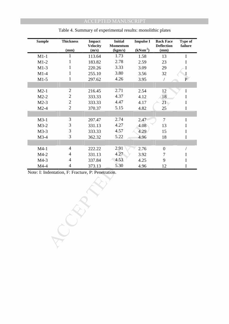
before and after tests were taken and some typical photographs are shown in Fig. 3. The
deformation of the projectiles at different impact velocities is shown in Fig. 4. The final
deformation of all the back-face sheet and the core were measured using a vernier calliper
after cutting the samples along the middle span.
Another group of tests to record the back-face deflection history were conducted at a gun
pressure of 1000 kPa; where at this pressure, none of the sandwich panels were fully
penetrated by the foam projectile. This was to prevent damaging the laser displacement
sensor installed at the back of the sandwich panels. Only one sample each from sandwich

MANUSCRIP
T
ACCEPTED
ACCEPTED MANUSCRIPT
Groups A, B, C, D and monolithic plate of thickness 2 mm and 3 mm was used in these tests.
They were labelled as SB-A, SB-B, SB-C, SB-D, SB-M2 and SB-M3 in Table 5,
respectively.
4 Results and Discussions
Table 3 and Table 4 summarise the projectile impact velocity, initial momentum, impulse per
unit area, measured permanent back-face deflection and failure mode for the aluminium
honeycomb sandwich panels, the air sandwich panels and the monolithic plates, respectively.
The impulse per unit area generated by the foam projectiles, � , is calculated using the
formula proposed by Radford et al. [2].
� =�� (1)
where �is the density of the foam projectile, �is the original length of the projectile and
is the initial impact velocity of the foam projectile. For the second set of tests, which were
to record the deflection history, results for the sandwich panels and the monolithic plates are
shown in Table 5.
4.1 Deformation of honeycomb sandwich panels
The deformation of the front-face and the back-face of the honeycomb sandwich panels
occurred mainly by stretching and bending while deformation of the core was by progressive
buckling. The deformation at the centre of the back-face showed a nose–like shape (Fig. 3b).
The whole deformation process can be summarised as follows. Depending on the magnitude
of the projectile impulse, the deformation of the front-face progressed up to a maximum
before it started to fracture from excessive bending and stretching. Further increasing the
impulse promoted the fracture to propagate along the periphery of the projectile on the front-
face. At the same time, the core buckled progressively up to full compression. Similar to the

MANUSCRIP
T
ACCEPTED
ACCEPTED MANUSCRIPT
front-face, the back-face was deformed by bending and stretching, which led to full
penetration at high impulse level.
Deformation and failure modes of the sandwich panels in the current study are found to be
very similar to those observed in the actual blast loading [19]. Therefore, the same argument
as presented in [19] will be followed here and the results have been characterised into two
groups, i.e., (1) experimental observations and (2) quantitative results.
The experimental observations include the description of the deformation modes and the
failure modes of the front-face, the back-face and the honeycomb core. The quantitative
results are associated with the impulse applied to the sandwich panels, the permanent back-
face deflections and the histories of the back-face deformation captured by the laser
displacement sensor.
4.1.1 Experimental observation
Two deformation modes were observed: global deformation and localised deformation.
Global deformation is defined as the deformation that reaches the area up to the sandwich
clamped edges and it is labelled as Mode G. Localised deformation describes the situation
when the deformation area has been limited to the projectiles cross sectional area and when
there is no evidence of the plastic hinge line along the clamped edges. Localised deformation
has been labelled as Mode L.
The failure mode can be categorised into three types: Type I for indentation, Type F for
fracture and Type P for penetration, as shown in Fig. 5. Type I is defined when there is
deformation on the face without any fracture. Type F is defined when fracture is present and

MANUSCRIP
T
ACCEPTED
ACCEPTED MANUSCRIPT
starts to propagate. Type P is defined when the projectile penetrates and passes through the
face sheets of the sandwich panels. When Type P failure occurs, tensile tearing damage is
dominant at the centre while very limited deformation is observed in the remaining part of the
sandwich panel. The overall deformation modes and the failure modes for all the sandwich
panels are summarised in Fig. 6.
In order to study the deformation of the core, samples A2, B2, C2 and D2, which were tested
at similar impulses, were sectioned along the central axis as shown in Fig.7. The core
deformation was measured using a vernier calliper and the mean compression strain of the
core was calculated accordingly as follows.
�� =∆�
� (2)
where ∆� is the reduction in the core height and c is the initial core height. From the figure, it
is evident that the magnitude of the core compression is larger at the centre of the sandwich
panels and it decreases towards the edges of the sandwich panels. Due to the difference in the
magnitude, the cross section of the sandwich panels may be divided into three regions as
shown in Fig. 7. They are: (1) Fully Folding Region, (2) Partly Folding Region, and (3)
Folding Absent Region as proposed by Zhu et al. [19].
Similar deformation was also reported in [4, 9, 10, 20]. Almost full compression of the core
can be seen in sample A2 which has a core compression ratio of 91%. The core compression
ratio of sample B2 and sample C2 were 50% and 79%, respectively. No core compression
was observed in sample D2, with only bending of the core. The core used in sample D2 is the
densest core with a density of 192.22 kgm-3 and the � ��⁄ ratio of 0.0240.
4.1.2 Quantitative results

MANUSCRIP
T
ACCEPTED
ACCEPTED MANUSCRIPT
The permanent back-face deflections of all the honeycomb sandwich panels against impulses
are shown in Fig. 8. Sandwich Group D behaved differently from the other honeycomb
sandwich panels as the fitting line shows almost a linear line. The density of the honeycomb
core in sandwich Group D is almost 4 times the density of the honeycomb core in sandwich
Group A, which is the weakest sandwich group. Linear relations were observed when steel
plates were used as the skin and when there was no fracture of the front plate [9-11].
As a very crude estimate, the back-face deformation, δ, is proportional to the applied impact
energy e and � =�
�� �, where � is the mass of the projectile in kg and is the impact
velocity in ms-1. From Eq. (1), =�
���� , therefore, � ∝ (
�
��� �� )�
�. In order to check the
relation between the permanent back-face deflection and impulse, a log-log graph of the
deflection is drawn as shown in Fig. 9. The slopes of the graphs vary from 2 to 2.6, which
indicate that the back-face deflection and the impulse are related by a power relation. In-
depth theoretical analysis is required in order to determine the relationship between the back-
face deflection and the applied impulse accurately.
The effects of doubling the foil thickness and increasing the cell size by one and half of the
honeycomb core are summarized in Table 6 and Table 7, respectively. Honeycomb Group A
and B differs in the foil thickness while honeycomb Group B and C differs in the cell size.
Difference in the magnitude of compressive yield stress can be observed from Table 1.
Doubling the foil thickness increases the compressive yield stress to almost triple while
increasing the cell size by one and a half reduces the compressive yield stress to almost half.
Using the weaker core, which is sandwich Group A in Table 6 and Group C in Table 7, as a
reference for the comparison, the percentage reduction of the back-face are calculated at
similar impulse. The data demonstrates that the percentage reduction of the back-face is

MANUSCRIP
T
ACCEPTED
ACCEPTED MANUSCRIPT
significant at low impulse. The average percentage reduction of the back-face deflection is
55% when doubling the foil thickness and is 36% when the cell size is reduced from 4.763
mm to 3.175 mm.
4.2 Deflection history of honeycomb sandwich panels and monolithic plates
Figure 10 shows the typical back-face deflection history for samples SB-A, SB-B, SB-C, SB-
D, SB-M2 and SB-M3. From the Figure, the elastic spring-back which is defined as the
difference between the maximum deflection and the permanent deflection of the back-face, is
measured. The elastic spring-back for the sample SB-A, SB-B, SB-C, SB-D, SB-M2 and SB-
M3 are 2 mm, 4 mm, 2 mm and 3.5 mm, 2.5 mm and 3 mm respectively as shown in Table 5.
The largest spring-back is 4 mm attained by sample SB-B and 3 mm attained by monolithic
plate SB-M3. The result illustrates that honeycomb sandwich panels do not have a significant
influence on the elastic spring-back effect compared with monolithic plates at the impulse
level studied.
4.3 Comparison between honeycomb sandwich panels, air sandwich panels and
monolithic plates
Six samples of air sandwich panels (sandwich Group G) were tested and the results are listed
in Table 3. Photographs of the air sandwich panels before and after the tests are shown in Fig.
3c. The impact velocities were varied from 103 m/s to 365 m/s. The permanent back-face
deflection of the air sandwich panels were compared with that of sandwich Groups A, B and
C (representing sandwich panel structure). The comparison can be seen in Fig. 11. Sandwich
Groups D and E were omitted in the figure for clarity.

MANUSCRIP
T
ACCEPTED
ACCEPTED MANUSCRIPT
Each group was represented by the best fitted line. However, limited data for each group (4
points) was due to the following two reasons:
1. Large size of samples (300 mm×300 mm) and limited stock of honeycomb cores;
2. The maximum impulse that can be generated by the current testing equipment. The
gas gun employed in this study (barrel length of 3 m and diameter of 38 mm) has a
maximum operational pressure of 2 MPa. This maximum pressure could speed up the
foam projectile up to 370 m/s. At this impact velocity, the impulse per unit area was
around 5.5 kNsm-2.
The differences can be summarised by dividing the graph into three different regions
according to the intersection of sandwich Group G with sandwich Group A (the weakest
sandwich group) and with sandwich Group B (the strongest sandwich group in the
comparison) as shown in Fig. 11. The regions are classified as low impulse region, medium
impulse region and high impulse region. The low impulse region covers from 0 to 2.3 kNsm-
2. In this region, the air sandwich panels perform better than the honeycomb sandwich panels
in minimising the back-face deflection. The front-face sheet of the air sandwich panels has
ample time and space to deform before it reaches the back-face sheet. Mode G deformation is
observed at the front-face sheets of the air sandwich panels which indicates more energy
being absorbed by the front-face sheets. As a comparison, the front-face sheets of the
honeycomb sandwich panels show Mode L deformation. For sample G1, the front-face sheet
of the air sandwich panel deforms individually even at an impulse level of 1.57 kNsm-2, and
therefore there is no back-face deformation.
When the deformation of the front-face sheet of an air sandwich panel reaches 12.7 mm, the
remainder of the impact energy is then transferred to the back-face sheet and this deforms it.

MANUSCRIP
T
ACCEPTED
ACCEPTED MANUSCRIPT
The contact area between the front-face sheet and the back-face sheet is larger due to Mode G
deformation of the front-face sheet. This phenomenon further reduces the stress concentration
on the back-face sheet thus reducing the deflection.
The advantage of the air sandwich panels against the honeycomb sandwich panels ceases
when the impulse reaches 2.3 kNsm-2. This is the beginning of the medium impulse region
which covers up to 4.70 kNsm-2. At an impulse level of 2.3 kNsm-2, sandwich Group A,
which is the weakest sandwich group, starts to deform less than the air sandwich panels. In
this region, the progressive buckling of the honeycomb core absorbs a large amount of impact
energy and reduces the back-face deflection.
The third region is the high impulse region which covers an impulse level from 4.70 kNsm-2
and beyond. In this region the air sandwich panels again outperformed the honeycomb
sandwich panels. Fracture of the front-face sheets are observed in all honeycomb sandwich
panels in this region. It is believed that the fracture has weakened the sandwich panels.
According to the test result conducted on monolithic plates M1-4 in Table 4, the aluminium
face sheet of 1 mm thick can deform up to 32 mm before fracture. The stress concentration
that developed at the interface between the front-face sheet and the core edges has weakened
the face sheet and limited the face sheet to deform more before fracture. Also according to
the result of testing monolithic plates M1-4, the air sandwich panels can be further optimised
by increasing the gap between the two plates to 32 mm.
Figure 11 also shows the comparison between the air sandwich panels and the monolithic
plates of thickness 2 mm at increasing impulses. This comparison indicates that the air

MANUSCRIP
T
ACCEPTED
ACCEPTED MANUSCRIPT
sandwich panels outperform the monolithic plates of equivalent mass at all impulse regions
applied in this study.
A similar observation was reported by Roach at el. [21] where it was concluded that the panel
specially designed to absorb energy might best be constructed from a series of thin laminates
with air spaces, rather than from single thick laminates or a laminate with core. The distance
between the laminates should be sufficient to allow for plate deflection during the
deformation process. However, the ballistic limit, which was defined as the velocity just
enough to have a penetration, of sandwich panels was higher compared to parallel plate
without core as observed by Hou at el. [22]. Note that projectiles made of solid materials,
rather than aluminium foam, were used in both [20] and [21].
4.4 Comparison between honeycomb sandwich panels with monolithic plates
The back-face deflections of the honeycomb sandwich panels have been compared with the
deflection of the monolithic plates with equivalent mass. The deflections of the plates at
various impulse levels were recorded and shown in Table 4 (samples M1-1 to M4-4). At least
4 different impulses were loaded to the plates with the same thickness. In order for the
monolithic plates to have the same equivalent mass as the honeycomb sandwich panels, the
monolithic plates need to have a thickness of 2.55 mm, 2.84 mm, 2.71 mm, 3.36 mm and
2.80 mm for sandwich groups A, B, C, D and E respectively, which was impossible
practically. Hence the data for the required plate thickness have been generated using
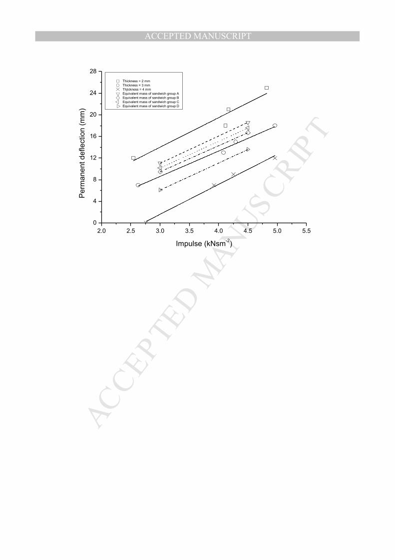
interpolation in-between the experimental results, as shown in Fig. 12.
The permanent back-face deflection of the honeycomb sandwich panels and the monolithic
plates have been compared in Fig. 13. In this figure, only sandwich Group A, Group B and

MANUSCRIP
T
ACCEPTED
ACCEPTED MANUSCRIPT
Group C are used for the comparison with the monolithic plates with equivalent mass.
Sandwich Group E has been omitted because panels’ properties are almost similar to the
properties of sandwich Group A. Sandwich panels in group D are relatively strong and the
experimental data points do not representing the general behaviour of the sandwich panels.
The sandwich panels should be loaded with projectile at higher impact velocity however; this
test is unable to be carried out due to equipment limitation. Therefore, due to the insufficient
data point especially at higher impulse to describe the deformation, sandwich Group D has
also been omitted from the comparison.
From Fig. 13, the honeycomb sandwich panels outperform their monolithic plates of
equivalent mass up to a critical impulse. Beyond this critical impulse, the honeycomb
sandwich panels deform more. The critical impulse for sandwich Groups A, B and C are 4.3
kNsm-2, 4.8 kNsm-2 and 4.6 kNsm-2 respectively. Similar observations have also been
reported [11] and it was concluded that the accumulated plastic strains that develop in the
front-face of the sandwich panels exceed those in the monolithic plate at relatively high
impulse.
5 Conclusions
Honeycombs sandwich panels with 1 mm thick aluminium face sheets and five different
honeycomb core configurations have been impacted with aluminium foam projectiles at
various speeds. The back-face deflection of the honeycomb sandwich panels has been
recorded and compared to determine the effect of the core configurations. It has been found
that the foil thickness and the cell size of the core affect the back-face deflection of the
honeycomb sandwich panels. Increasing the foil thickness and reducing the cell size led to a
decrease in the back-face deflection, but increases the overall honeycomb sandwich panels’

MANUSCRIP
T
ACCEPTED
ACCEPTED MANUSCRIPT
weight. Optimization between impact resistance and weight of a honeycomb sandwich panel
design is one of the important issues that need to be considered in future.
The use of honeycomb sandwich panels in absorbing the impact energy of aluminium foam
projectiles is limited by the operational impulse range. The operational impulse range has to
be determined to ensure the effectiveness of the sandwich panels as a protective structure.
Beyond the operational range, replacement of honeycomb sandwich panels with air sandwich
panels or monolithic plates of equivalent mass can be more favourable.
It was found that a honeycomb sandwich panel has to deform as an integral structure (face
sheets and honeycomb core deform together) in order to effectively absorb impact energy and
minimise the back-face deflection. Selection of components in constructing a sandwich panel
is important in order to ensure the optimum performance of the panel. The core must allow
the front-face to deform to its maximum before fracture. Once the front-face fractures, the
overall impact resistance of the sandwich panels reduces significantly.
Acknowledgements
The Authors wish to acknowledge the Australian Research Council for the support through a
Discovery Grant and the support of the Defence Materials Technology Centre, which was
established and is supported by the Australian Government’s Defence Future Capability
Technology Centre (DFCTC) initiative.
References
[1] G. Lu, T.X. Yu, Energy Absorption of Structures and Materials, CRC Press, 2003.

MANUSCRIP
T
ACCEPTED
ACCEPTED MANUSCRIPT
[2] D.D. Radford, V.S. Deshpande, N.A. Fleck, The use of metal foam projectiles to simulate
shock loading on a structure, Int. J. Impact Eng. 31 (2005) 1152-1171.
[3] D.D. Radford, N.A. Fleck, V.S. Deshpande, The response of clamped sandwich beams
subjected to shock loading, Int. J. Impact Eng. 32 (2006) 968-987.
[4] H.J. Rathbun, D.D. Radford, Z. Xue, M.Y. He, J. Yang, V.S. Deshpande, N.A. Fleck,
J.W. Hutchinson, F.W. Zok, A.G. Evans, Performance of metallic honeycomb-core
sandwich beams under shock loading, Int. J. Solids Struct. 43 (2006) 1746-1763.
[5] V.L. Tagarielli, V.S. Deshpande, N.A. Fleck, The dynamic response of composite
sandwich beams to transverse impact, Int. J. Solids Struct. 44 (2007) 2442-2457.
[6] V. Rubino, V.S. Deshpande, N.A. Fleck, The dynamic response of end-clamped sandwich
beams with a Y-frame or corrugated core, Int. J. Impact Eng. 35 (2008) 829-844.
[7] V.L. Tagarielli, V.S. Deshpande, N.A. Fleck, Prediction of the dynamic response of
composite sandwich beams under shock loading, Int. J. Impact Eng. 37 (2010) 854-864.
[8] B.P. Russell, T. Liu, N.A. Fleck, V.S. Deshpande, The soft impact of composite sandwich
beams with a square-honeycomb core, Int. J. Impact Eng. 48 (2012) 65-81.
[9] D.D. Radford, G.J. McShane, V.S. Deshpande, N.A. Fleck, The response of clamped
sandwich plates with metallic foam cores to simulated blast loading, Int. J. Solids Struct.
43 (2006) 2243-2259.
[10] G.J. McShane, D.D. Radford, V.S. Deshpande, N.A. Fleck, The response of clamped
sandwich plates with lattice cores subjected to shock loading, Eur. J. Mech. A-Solids 25
(2006) 215-229.
[11] V. Rubino, V.S. Deshpande, N.A. Fleck, The dynamic response of clamped rectangular
Y-frame and corrugated core sandwich plates, Eur. J. Mech. A-Solids 28 (2009) 14-24.
[12] J.Shen, G. Lu, Z.H. Wang and L.M. Zhao, Experiments on curved sandwich panels
under blast loading. Int. J. Impact Eng. 37 (2010) 960-970.

MANUSCRIP
T
ACCEPTED
ACCEPTED MANUSCRIPT
[13] S.M. Pingle, N.A. Fleck, H.N.G. Wadley, V.S. Deshpande, Discrete element calculations
of the impact of a sand column against rigid structures, Int. J. Impact Eng. 45 (2012) 74-
89.
[14] Columbia Accident Investigation Board, Report Volume 1, NASA, 2003.
[15] J.D. Walker, From Columbia to Discovery: Understanding the impact threat to the space
shuttle, Int. J. Impact Eng. 36 (2009) 303-317.
[16] A. Neuberger, S. Peles, D. Rittel, Springback of circular clamped armor steel plates
subjected to spherical air-blast loading, Int. J. Impact Eng. 36 (2009) 53-60.
[17] E.W. Andrews, G. Gioux, P. Onck, L.J. Gibson, Size effects in ductile cellular solids.
Part II: Experimental results, Int. J. Mech. Sci. 43 (2001) 701-713.
[18] FORTIS AD825 Product Data, http://fortisadhesives.com/adhesives.php, viewed on 1st April 2014.
[19] F. Zhu, L. Zhao, G. Lu, Z. Wang, Deformation and failure of blast-loaded metallic
sandwich panels—Experimental investigations, Int. J. Impact Eng. 35 (2008) 937-951.
[20] M.T. Tilbrook, D.D. Radford, V.S. Deshpande, N.A. Fleck, Dynamic crushing of
sandwich panels with prismatic lattice cores, Int. J. Solids Struct. 44 (2007) 6101-6123.
[21] A.M. Roach, K.E. Evans, N. Jones, The penetration energy of sandwich panel elements
under static and dynamic loading. Part I, Compos. Struct. 42 (1998) 119-134.
[22] W. Hou, F. Zhu, G. Lu, D.N. Fang, Ballistic impact experiments of metallic sandwich
panels with aluminium foam core, Int. J. Impact Eng. 37 (2010) 1045-1055.

MANUSCRIP
T
ACCEPTED
ACCEPTED MANUSCRIPT
Captions of figures
Fig. 1. Impact experimental set-up.
Fig. 2. Quasi-static testing of aluminium alloy 5005 H34: (a) sketch of sample dimensions; (b) stress-strain curves obtained from three repeated tests of samples with 1 mm, 3 mm and 5 mm thickness respectively; (c) typical stress- strain curves of samples with 1 mm, 2 mm, 3 mm, 4 mm and 5 mm thickness.
Fig. 3. Photographs showing typical deformation of (a) a monolithic plate (sample M1-2); (b) a honeycomb sandwich panel (sample B4); (c) an air sandwich panel (sample G6).
Fig. 4. Photographs of aluminium foam projectiles: (a) initial shape; (b) and (c) after tests at 189.39 m/s and 333.33 m/s impact velocities, respectively.
Fig. 5. Typical failure modes of the front-face of honeycomb sandwich panels: (a) Type P (penetration) (b) Type F (fracture); (c) Type I (indentation)
Fig. 6. Deformation modes and failure modes of honeycomb sandwich panels with different core configurations.
Fig. 7. Four specimens showing core compression ratio reduces from the centre towards the edges of the sandwich panels. From top to bottom: samples A2, B2, C2 and D2.
Fig. 8. Permanent back-face deflection of honeycomb sandwich panels at various impulse levels.
Fig. 9. The log-log graph of the permanent back-face deflection of honeycomb sandwich panels vs. impulse.
Fig. 10. Typical back-face deflection histories of honeycomb sandwich panels and monolithic plates.
Fig. 11. Permanent back-face deflection of the honeycomb sandwich panels (Groups A, B and C) , the air sandwich panels (Group G) and 2 mm monolithic plates.
Fig. 12. Permanent deflection of the monolithic plates.
Fig. 13. Critical impulse of honeycomb sandwich panels Groups A, B and C.

MANUSCRIP
T
ACCEPTED
ACCEPTED MANUSCRIPT
Table 1. Properties of aluminium honeycombs in the out-of-plane direction (data were provided by the manufacturer)
Group Designation
Density ρ
Cell Size
Foil Thickness
t
Comp. Yield Stress
Modulus
(kg/m3
) (mm) (mm) (MPa) (GPa)
A 3.1-1/8-.0007
49.66 3.18 0.018 2.07 0.52 0.006
B 6.1-1/8-.0015
97.71 3.18 0.038 7.03 1.66 0.012
C 4.4-3/16-
.0015 70.48 4.76 0.038 3.78 1.00 0.008
D 12-1/8-.0030
192.22 3.18 0.076 19.96 6.21 0.024
E 3.4-1/4-.0015
54.46 6.35 0.038 2.55 0.62 0.006

MANUSCRIP
T
ACCEPTED
ACCEPTED MANUSCRIPT
Table 2. Properties of epoxy adhesive AD825 [13]
Elastic Modulus in
Compression (GPa)
Compressive Strength (MPa)
Tensile Bond Strength (Al/AI at
25°C) (MPa)
Flexural Strength (MPa)
Tensile Strength (MPa)
1.99 85-90 12 30 35

MANUSCRIP
T
ACCEPTED
ACCEPTED MANUSCRIPT
Table 3. Summary of experimental results: honeycomb sandwich panels
Sample
Honeycomb
Impact Velocity
(m/s)
Initial Momentum
(kgm/s)
Impulse I (kNsm-2)
Back Face Deflection
(mm)
Type of Failure Cell Size
(mm)
Foil Thickness
(mm)
Front Face Core
Back Face
A1 3.18 0.018 106.38 1.68 1.55 3 I I I A2 3.18 0.018 200.00 3.26 3.04 7 I I I A3 3.18 0.018 289.02 4.68 4.37 18 F I I A4 3.18 0.018 320.51 5.54 5.18 36 P F I A5 3.18 0.018 359.71 6.04 5.58 P P P P B1 3.18 0.038 109.17 1.71 1.54 1 I I I B2 3.18 0.038 189.39 3.03 2.81 4 I I I B3 3.18 0.038 292.40 4.50 4.20 8 I I I B4 3.18 0.038 357.14 5.64 5.24 27 P I I B5 3.18 0.038 354.61 5.35 5.13 26 P I I C1 12.70 0.038 111.11 1.77 1.62 2 I I I C2 12.70 0.038 203.25 3.15 2.94 5 I I I C3 12.70 0.038 285.71 4.71 4.39 13 F I I C4 12.70 0.038 324.68 5.06 4.74 22 P P F C5 12.70 0.038 367.65 6.23 5.32 P P P P D1 3.18 0.076 110.62 1.68 1.62 0 No deformation D2 3.18 0.076 198.41 3.35 3.12 6 I I I D3 3.18 0.076 280.90 4.75 4.45 15 I I I D4 3.18 0.076 333.33 5.87 5.51 17 F I I D5 3.18 0.076 352.11 6.23 5.49 20 F I I E1 6.35 0.038 154.32 2.25 2.14 3 I I I E2 6.35 0.038 228.31 3.40 3.25 5 I I I E3 6.35 0.038 314.47 4.47 4.31 14 F F I E4 6.35 0.038 349.65 5.10 4.90 28 P P F E5 6.35 0.038 375.94 5.38 5.23 P P P P G1 103.31 1.64 1.57 0 I / G2 200.00 3.22 3.01 7 I I G3 310.56 5.03 4.83 16 I I G4 352.11 5.42 5.24 19 I I G5 354.61 5.67 5.41 24 P F G6 364.96 5.84 5.55 P P P
Note: I: Indentation, F: Fracture, P: Penetration.
MANUSCRIP
T
ACCEPTED
ACCEPTED MANUSCRIPT
Table 4. Summary of experimental results: monolithic plates
Sample Thickness
(mm)
Impact Velocity
(m/s)
Initial Momentum
(kgm/s)
Impulse I
(kNsm-2)
Back Face Deflection
(mm)
Type of failure
M1-1 1 113.64 1.73 1.58 13 I M1-2 1 183.82 2.78 2.59 23 I M1-3 1 220.26 3.33 3.09 29 I M1-4 1 255.10 3.80 3.56 32 I M1-5 1 297.62 4.26 3.95 / P
M2-1 2 216.45 2.71 2.54 12 I M2-2 2 333.33 4.37 4.12 18 I M2-3 2 333.33 4.47 4.17 21 I M2-4 2 370.37 5.15 4.82 25 I
M3-1 3 207.47 2.74 2.47 7 I M3-2 3 331.13 4.27 4.08 13 I M3-3 3 333.33 4.57 4.29 15 I M3-4 3 362.32 5.22 4.96 18 I
M4-1 4 222.22 2.91 2.76 0 / M4-2 4 331.13 4.27 3.92 7 I M4-3 4 337.84 4.53 4.25 9 I M4-4 4 373.13 5.30 4.96 12 I
Note: I: Indentation, F: Fracture, P: Penetration.

MANUSCRIP
T
ACCEPTED
ACCEPTED MANUSCRIPT
Table 5. Summary of experimental results: the spring-back effect of honeycomb sandwich panels and monolithic plates
Sample Gas Gun
Pressure (kPa)
Impulse I
(kNsm-2)
Maximum Deflection
(mm)
Final Deflection
(mm)
Spring back (mm)
SB-A 1000 3.77 15.0 13.5 1.5
SB-B 1000 3.82 14.0 10.0 4.0
SB-C 1000 3.89 14.0 12.0 2.0
SB-D 1000 3.77 6.5 3.0 3.5
SB-M2 1000 3.81 22.5 20.0 2.5
SB-M3 1000 3.66 19.0 16.0 3.0

MANUSCRIP
T
ACCEPTED
ACCEPTED MANUSCRIPT
Table 6. The comparison between sandwich panels Group A and sandwich panels Group B (The aluminium honeycomb core in sandwich panels Group B has the same cell size, but
double foil thickness as that in sandwich panels Group A.)
Pressure
(kPa)
Ave. Impulse
(kNsm-2)
Deflection Back-face deflection reduction
(%) Sandwich A
(mm) Sandwich B
(mm)
200 1.55 3 1 67 500 2.93 7 4 43
1000 4.29 18 8 56

MANUSCRIP
T
ACCEPTED
ACCEPTED MANUSCRIPT
Table 7. The comparison between sandwich panels Group B and sandwich panels Group C (The aluminium honeycomb core in sandwich panels Group C has the same foil thickness,
but larger cell size as that in sandwich panels Group B.)
Pressure
(kPa)
Ave. Impulse
(kNsm-2)
Deflection Back face deflection reduction
(%) Sandwich B
(mm) Sandwich C
(mm)
200 1.58 1 2 50 500 2.88 4 5 20
1000 4.29 8 13 38

MANUSCRIP
T
ACCEPTED
ACCEPTED MANUSCRIPT
Nitrogen Gas Tank
Pressure Regulator
Barrel of
Gas Gun Velocity Meter
Sample Holder Laser
Displacement
Sensor
Front View of
Sample Holder
I-Beam
Gas
Chamber

MANUSCRIP
T
ACCEPTED
ACCEPTED MANUSCRIPT
(Dimensions are in mm)
0.00 0.02 0.04 0.06 0.08 0.10 0.12
0
20
40
60
80
100
120
140
160
180 1mm-1 1mm-2 1mm-3
3mm-1 3mm-2 3mm-3
5mm-1 5mm-2 5mm-3
Engin
eering s
tress (
MP
a)
Engineering strain
0.00 0.02 0.04 0.06 0.08 0.10 0.12
0
20
40
60
80
100
120
140
160
180
Engin
eering s
tress
(M
Pa)
Engineering strain
1mm 2mm 3mm 4mm 5mm(b)
(a)
(b)
(c)
MANUSCRIP
T
ACCEPTED
ACCEPTED MANUSCRIPT
Initial shape After tests: front-face After tests: back-face
(a)
(c)
(b)

MANUSCRIP
T
ACCEPTED
ACCEPTED MANUSCRIPT
(a) (b) (c)

MANUSCRIP
T
ACCEPTED
ACCEPTED MANUSCRIPT
(a) (b) (c)

MANUSCRIP
T
ACCEPTED
ACCEPTED MANUSCRIPT
0 1 2 3 4 5 6 7
1.0
1.5
2.0
2.5
3.0
3.5
4.0
4.5
5.0
5.5
6.0
I
I
I
I
P
I
I
I
II
I
I
I
F
P
I
I
II
I
I
I
F
P
I
I
IFP
No deformationDeformation Mode G
A
A
GEDCA B
Imp
uls
e (
kN
sm
-2)
Sandwich Group
A
Deformation Mode L

MANUSCRIP
T
ACCEPTED
ACCEPTED MANUSCRIPT
Fully Folding Region Partly Folding Region Folding Absent Region

MANUSCRIP
T
ACCEPTED
ACCEPTED MANUSCRIPT
1 2 3 4 5 6
0
5
10
15
20
25
30
35
40 Sandwich Group A
Sandwich Group B
Sandwich Group C
Sandwich Group D
Sandwich Group E
Pe
rma
ne
nt b
ack-f
ace
de
fle
ctio
n (
mm
)
Impulse (kNsm-2)

MANUSCRIP
T
ACCEPTED
ACCEPTED MANUSCRIPT
1 2 3 4 5 6
0.1
1
10
Sandwich Group A
Sandwich Group B
Sandwich Group C
Sandwich Group D
Sandwich Group E
Sandwich Group A (slope = 2.0)
Sandwich Group B (slope = 2.6)
Sandwich Group C (slope = 2.1)
Sandwich Group D (slope = 2.0)
Sandwich Group E (slope = 2.6)
Pe
rma
ne
nt b
ack-f
ace
de
fle
ctio
n (
mm
)
Impulse (kNsm-2)

MANUSCRIP
T
ACCEPTED
ACCEPTED MANUSCRIPT
0 2 4 6 8 10 12 14 16
0
5
10
15
20
25
30B
ack-f
ace
de
fle
ctio
n (
mm
)
Time (ms)
Sample SB-A (I=3.77 kNsm-2) Sample SB-C (I=3.89 kNsm
-2)
Sample SB-B (I=3.82 kNsm-2) Sample SB-D (I=3.77 kNsm
-2)
Sample SB-M2 (I=3.81 kNsm-2) Sample SB-M3 (I=3.66 kNsm
-2)

MANUSCRIP
T
ACCEPTED
ACCEPTED MANUSCRIPT
1.0 1.5 2.0 2.5 3.0 3.5 4.0 4.5 5.0 5.5
0
5
10
15
20
25
30
35
40
High
Impulse
Medium
Impulse
Sandwich Group A
Sandwich Group B
Sandwich Group C
Sandwich Group G
M2 Monolithic plate thickness = 2mm
Pe
rma
ne
nt b
ack-f
ace
de
fle
ctio
n (
mm
)
Impulse (kNsm-2)
Low
Impulse
MANUSCRIP
T
ACCEPTED
ACCEPTED MANUSCRIPT
2.0 2.5 3.0 3.5 4.0 4.5 5.0 5.5
0
4
8
12
16
20
24
28
Thickness = 2 mm
Thickness = 3 mm
Thjickness = 4 mm
Equivalent mass of sandwich group A
Equivalent mass of sandwich group B
Equivalent mass of sandwich group C
Equivalent mass of sandwich group D
Pe
rma
ne
nt d
efle
ctio
n (
mm
)
Impulse (kNsm-2)

MANUSCRIP
T
ACCEPTED
ACCEPTED MANUSCRIPT
0.0 0.5 1.0 1.5 2.0 2.5 3.0 3.5 4.0 4.5 5.0 5.5
0
5
10
15
20
25
30
35
40 Sandwich Group A
Sandwich Group C
Monolithic plate with equivalent areal mass as sandwich group A
Monolithic plate with equivalent areal mass as sandwich group C
Pe
rma
ne
nt b
ack-f
ace
de
fle
ctio
n (
mm
)
Impulse (kNsm-2)
4.25 kNsm-2
(a)
0.0 0.5 1.0 1.5 2.0 2.5 3.0 3.5 4.0 4.5 5.0 5.5
0
5
10
15
20
25
30
35
40 Sandwich Group B
Sandwich Group C
Monolithic plate with the equivalent mass as sandwich C
Monolithic plate with the equivalent mass as sandwich B
Pe
rma
ne
nt b
ack-f
ace
de
fle
ctio
n (
mm
)
Impulse (kNsm-2)
4.60 kNsm-2
4.80 kNsm-2
(b)

MANUSCRIP
T
ACCEPTED
ACCEPTED MANUSCRIPT
Highlights
• The effects of core properties towards minimising the back-face deflection of honeycomb
core sandwich panels upon impact by foam projectiles were studied.
• The back-face deflections of the sandwich panels were also compared with monolithic plate
of equivalent mass and air sandwich panels.
• Histories of the back-face deflections were also recorded using a laser displacement sensor.
• Advantages and limitations of sandwich panels compared with monolithic plates of
equivalent mass and air sandwich panels were discussed.