Response Modification Factor of Coupled Steel … factor of coupled steel shear wall frames with...
12
Civil Engineering Infrastructures Journal, 46(1): 15 – 26, June 2013 ISSN: 2322 – 2093 * Corresponding author E-mail: [email protected] 15 Response Modification Factor of Coupled Steel Shear Walls Abdollahzadeh, G. 1* and Malekzadeh, H. 2 1 Assistant Professor, Faculty of Civil Engineering, Babol University of Technology, Babol, Iran. 2 M.Sc. Student, Department of Civil Engineering, College of Engineering, University of Shomal, Amol, Iran. Received: 30 Jun. 2011; Revised: 12 Jan. 2012; Accepted: 10 Mar. 2012 ABSTRACT: The present research is concerned with the determination of ductility, over- strength and response modification factors of coupled steel shear wall frames. Three structural models with various numbers of stories, bay width and coupling beam height were analyzed using static pushover and incremental nonlinear dynamic analyses. The ductility, over-strength and response modification factors for the three models are determined. Tentative values of 11.1, 11.6 and 10.6 are suggested for the response modification factor of coupled steel shear wall frames with deep and medium depth coupling beams, and uncoupled steel shear wall frames, respectively in the allowable stress design method. Keywords: Coupled Steel Shear Walls, Ductility Reduction Factor, Incremental Nonlinear Dynamic Analysis, Over Strength Reduction Factor, Response Modification Factor, Static Pushover Analysis. INTRODUCTION During recent decades, ductile steel shear walls have been used as lateral load resistant systems in design and retrofit of civil engineering structures. Proper behaviour of this system regarding stiffness, strength, ductility, energy absorption and stability of hysteresis loops strengthens the idea of its application in seismic design of the structures. A coupled shear wall system consisting of steel fill plates bounded with the column- beam system resembles a cantilever plate girder where the plate, columns and beams of the system act as the web, flanges and stiffeners of the girder, respectively. However, the strength and stiffness of the beams and columns of the steel shear wall frame have more effects on the system behaviour compared with the flanges and stiffeners of the plate girder. The flexural members coupling the shear walls increase stiffness of the system. Under lateral loads, the plate buckles and resists by forming a diagonal tension field. Even for high steel shear walls and large shear loads, high post buckling resistance of the steel plates facilitates the application of thin plates in the coupled shear wall system. The reduction of structural weight, increase of lateral stiffness, reduction of dimensions of beams and columns and easy and fast implementation are some of advantages of
Transcript of Response Modification Factor of Coupled Steel … factor of coupled steel shear wall frames with...
Civil Engineering Infrastructures Journal, 46(1): 15 – 26, June 2013
ISSN: 2322 – 2093
* Corresponding author E-mail: [email protected]
15
Response Modification Factor of Coupled Steel Shear Walls
Abdollahzadeh, G.1*
and Malekzadeh, H.2
1 Assistant Professor, Faculty of Civil Engineering, Babol University of Technology, Babol,
Iran. 2 M.Sc. Student, Department of Civil Engineering, College of Engineering, University of
Shomal, Amol, Iran.
Received: 30 Jun. 2011; Revised: 12 Jan. 2012; Accepted: 10 Mar. 2012
ABSTRACT: The present research is concerned with the determination of ductility, over-
strength and response modification factors of coupled steel shear wall frames. Three
structural models with various numbers of stories, bay width and coupling beam height
were analyzed using static pushover and incremental nonlinear dynamic analyses. The
ductility, over-strength and response modification factors for the three models are
determined. Tentative values of 11.1, 11.6 and 10.6 are suggested for the response
modification factor of coupled steel shear wall frames with deep and medium depth
coupling beams, and uncoupled steel shear wall frames, respectively in the allowable stress
design method.
Keywords: Coupled Steel Shear Walls, Ductility Reduction Factor, Incremental Nonlinear
Dynamic Analysis, Over Strength Reduction Factor, Response Modification Factor, Static
Pushover Analysis.
INTRODUCTION
During recent decades, ductile steel shear
walls have been used as lateral load resistant
systems in design and retrofit of civil
engineering structures. Proper behaviour of
this system regarding stiffness, strength,
ductility, energy absorption and stability of
hysteresis loops strengthens the idea of its
application in seismic design of the
structures.
A coupled shear wall system consisting of
steel fill plates bounded with the column-
beam system resembles a cantilever plate
girder where the plate, columns and beams
of the system act as the web, flanges and
stiffeners of the girder, respectively.
However, the strength and stiffness of the
beams and columns of the steel shear wall
frame have more effects on the system
behaviour compared with the flanges and
stiffeners of the plate girder. The flexural
members coupling the shear walls increase
stiffness of the system. Under lateral loads,
the plate buckles and resists by forming a
diagonal tension field. Even for high steel
shear walls and large shear loads, high post
buckling resistance of the steel plates
facilitates the application of thin plates in the
coupled shear wall system. The reduction of
structural weight, increase of lateral
stiffness, reduction of dimensions of beams
and columns and easy and fast
implementation are some of advantages of

Abdollahzadeh, G. and Malekzadeh, H.
16
this system compared with the concrete
shear wall system. Also, in contrast with
braced frames, this system has the privilege
of decentralization of seismic energy from
beam-to-column connection joints and the
increase of ductility and feasibility of
replacing damaged plates after earthquakes.
In this regard, Kulak (1985); Elgaaly et al.
(1993); Lubell et al. (2000); Rezai (1999);
Thorburn et al. (1983); Timler et al. (1998)
and Tromposch et al. (1987) assessed the
behavior of steel shear walls under static and
dynamic loads.
Wagner (1931) and Driver et al. (1998)
proposed a modified strip model for
analyzing steel shear walls, consisting of
thin plates without stiffener, by substituting
some inclined truss members along the
diagonal tension field (Figure 1). The angle
of inclined truss members is determined
using the principle of minimum energy
consumption. Provided that the steel plate is
pretty thin, and that the beams and columns
are pretty stiff, α becomes 45º.
Fig. 1. Modified Strip Model (Driver et al., 1998).
Although the strip model is suitable for
estimation of the ultimate load of steel shear
walls with thin plate, it cannot be used for
steel shear walls consisting of thick plates,
those that lack stiffener or those that have
opening. To overcome such deficiencies
Roberts and Sabouri-Ghomi (1992) and
Sabouri-Ghomi and Gholhaki (2005)
presented a general model to analyze and
design different types of steel shear walls
regardless of whether they have thin plates,
stiffener and opening. In this model, first,
the behaviour of the steel plate and
surrounding frame are evaluated separately.
Next, the behaviour of the complete system
is evaluated using the super position
principle considering interaction of the plate
and frame. Astaneh-Asl (2001) developed
design methods of the coupled steel shear
wall considering ductility and over strength
of the system and ensuring that the ductile
failure modes precede brittle ones. In this
design method, inelasticity triggers in non-
gravity loads carrying members, if
necessary, spreads into gravity load carrying
ones towards the end of seismic event in a
controlled manner preventing progressive
collapse.
The application of coupled steel shear
wall systems in the seismic resistant design
of structures has seen a considerable
increase. On the other hand, common
structural analysis methods proposed in
seismic codes for typical low-rise and
regular high-rise structures are equivalent
static and spectral analysis procedures.
These issues expose the need for providing
more theoretical materials of coupled steel
shear wall systems. One of these materials is
the response modification factor that relates
linear analysis and nonlinear behaviour of
structures in the aforementioned analysis
methods. This is the main focus of the
present research. In this study, three
categories of coupled steel shear wall
systems designed based on various
provisions are evaluated using static
nonlinear and dynamic nonlinear analyses.
The ductility reduction factor, over-strength
reduction factor and response reduction
factor are finally proposed for typical
layouts of this system.
Civil Engineering Infrastructures Journal, 46(1): 15 – 26, June 2013
17
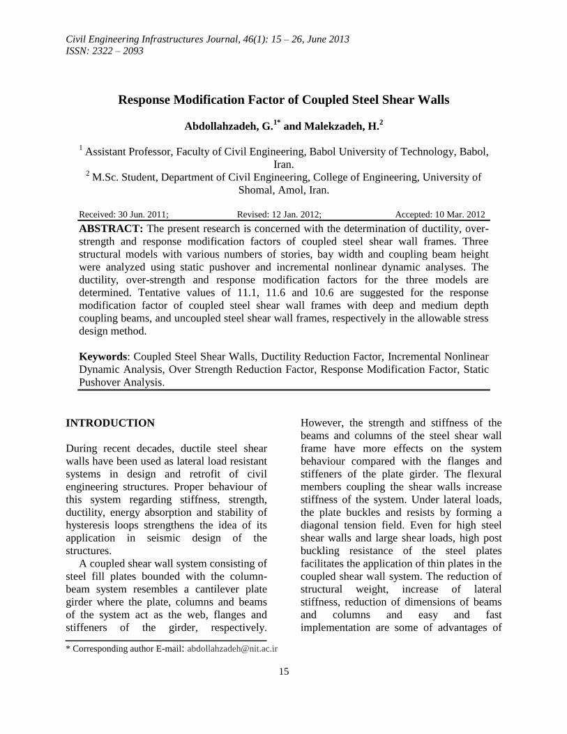
RESPONSE MODIFICATION FACTOR
In the equivalent linear static method, as the
common method proposed in most codes
(UBC97, 1997; NBCC, 2005, and BHRC,
2005) for seismic analysis of structures, the
lateral seismic loads are reduced by response
modification factor to be indirectly taken
into account for nonlinear behaviour of
structures. Mazzoni and Piluso (1996)
evaluated several theoretical approaches
such as the low cycle fatigue theory, energy
method and maximum plastic deformation
technique to evaluate the response
modification factor of structural systems. As
seen in Figure 2, the response modification
factor is the product of three factors
including the ductility reduction factor, Rμ,
over-strength reduction factor, Rs, and
redundancy factor, Y. In this figure, the
response modification factor is represented
as follows:
R =Ve
Vd (1)
where Ve is the maximum base shear
assuming elastic response for the structure
and Vd is the design base shear of the real
structure.
For the load and resistance factor design
method (AISC, 1999) and the allowable
stress design method (MHUD, 2006), the
value attributed to Vd is Vs as the base shear
corresponding to the first plastic hinge
formation in the structure, and Vw as the base
shear corresponding to the first allowable
stress exceedance in the structure,
respectively. Thus, Eq. (1) can be written as:
Ru =Ve
Vs (2)
Rw =Ve
Vw (3)
where Ru and Rw are the response
modification factors in the load and
resistance factor design method and
allowable stress design method, respectively.
The following relation can relate these two
variable one to another:
Y =Rw
Ru=
Vs
Vw (4)
where Y is the redundancy factor determined
based on the attitude of design codes for
design stress (i.e. yield stress and allowable
stress). The redundancy factor usually varies
between 1.4 to 1.7 and UBC97 (1997)
adopts the value of 1.4 for this factor.
Fig. 2. Definition of nonlinear parameters (Uang, 1991).

Abdollahzadeh, G. and Malekzadeh, H.
18
Rw = 1.4Ru (5)
Considering the ductility and over
strength, the response modification factor is
defined as:
Ru =Ve
Vs=
Ve
Vy×
Vy
Vs= Rμ × Rs (6)
where Vy as yield base shear is the
maximum base shear in the idealized elastic-
perfectly-plastic structure, Rμ =Ve
Vy is the
reduction factor resulting from the ductility
and Rs =Vy
Vs is the reduction factor resulting
from the over strength.
DAMAGE STANDARDS AND
STRUCTURAL MODELS
The performance of plastic hinges is
qualitatively evaluated using FEMA 273
(1997). The evaluation is undertaken based
on the ratio of hinge deformation to
corresponding yield deformations, and the
damage state of the whole structure is
specified by the status of performance point
as shown in Figure 3. In this figure, Q is the
action (i.e. moment or shear) at hinge, QCE
is the corresponding yield limit and Δ and θ
are the displacement and rotation of the
hinge, respectively. By having the
performance point in hand, the deformation
of structural elements and, hence,
strengthening requirements can be
determined. In the present study, nonlinear
hinge characteristics are defined using
FEMA 273 (1997). In addition to that,
response modification factors of structures
consisting of the special moment resisting
frame combined with coupled steel shear
walls are evaluated via nonlinear static
(pushover), linear dynamic and nonlinear
dynamic analyses using the SAP 2000
software (CSI, 1997).
Fig. 3. An example of force -deformation curve of
nonlinear hinges according to FEMA 273 (1997).
To assess the parameters affecting the
response modification factor, three
categories of structural models are
investigated including (A) coupled shear
wall systems with deep coupling beam, (B)
coupled shear wall systems designed based
on Astaneh-Asl (2001) recommendations,
AISC Seismic Provisions AISC (1997) and
FEMA-368 Provisions (FEMA 368, 2000)
and (C) uncoupled shear wall systems. In
each group three different number of stories
(i.e. 10, 12 and 15 stories) and three different
values of coupling beam bay width (i.e. 3, 4
and 5 meters) are selected. In total, 27
structural models are to be investigated. The
code of each model consists of the group
code, the number of bays, the number of
stories and the width of coupled bay
sequentially; for example, A_3_12_4
represent the frame from group A with 3
bays, 12 stories and coupled bay width of 4
m. For instance, the layout of the 10-story
frame is shown in Figure 4. In all models,
the typical story height and width of bays
normal to the frame plane are 3 meters and 4
meters, respectively.
Dead load and live load of floors are 550
kg/m2 and 200 kg/m
2, respectively, and the
partitions have the weight of 130 kg/m2. The
site has high seismic risk (i.e. Zone 3) and
subsoil of type III using the standard
described in BHRC (2005), (average shear
wave velocity from 175 m/s to 375 m/s in 30

Civil Engineering Infrastructures Journal, 46(1): 15 – 26, June 2013
19
meter depth top layer of soil). Equivalent
static lateral loads are used in the seismic
design procedure (BHRC, 2005) and a
preliminary value of 11.2 is used for the
response modification factor based on
Astaneh-Asl (2001). The modules of
elasticity, yield stress and ultimate stress of
the structural steel are 2.04×10⁶ kg/cm2,
2400 kg/cm2 and 3700 kg/cm
2, respectively.
Other assumptions are as follow:
• The steel plates are replaced with a series
of truss members (struts) along the tension
field.
• All frame members are connected
together by rigid connection except in group
C that the coupling beams are connected to
columns by the simple connection. In steel
structures, these connections have
considerable moment capacity and behave in
a “semi-rigid” manner rather than acting as a
pin connection as the current practice
assumes.
• For the dynamic analysis, story masses
are located in story levels considering the
rigidity of floor diaphragms.
• Idealized elastic-plastic behaviour with
maximum ductility of 4 and strain hardening
of 2% is considered for the members.
• The P-∆ effect is considered to include
geometric nonlinearities.
Fig. 4. Layout of the 10- story frame.
Abdollahzadeh, G. and Malekzadeh, H.
20
NUMERICAL RESULTS
To determine Vs, it is supposed that the
linear ultimate limits of the structure in the
nonlinear static analysis and nonlinear
dynamic analyses are the same Asgarian and
Shokrgozar (2009). After modelling the
frames, the base shear force is calculated
using the equivalent static loading model
specified in the Iranian Standard No. 2800
(BHRC, 2005). Using the model, loading is
distributed in height of the structures and the
structures are then subjected to non-linear
static (pushover) analysis.
To determine Vy, three severe Iranian
strong ground motion (Table 1) are initially
selected. To scale these records with respect
to the design spectrum, their PGAs are
altered iteratively in a way that the
calculated time history makes the structure
reach one of following failure criteria:
• Based on Iranian Standard No. 2800
(BHRC, 2005), the maximum inter-story
drift is limited to 0.025 H and 0.020 H for
the frames with the fundamental period less
than 0.7 sec and more than 0.7 sec,
respectively, where H is the story height.
• If story mechanism or overall mechanism
forms in the frame lead to loss of its stability
before reaching the inter-story drift limit, the
nonlinear dynamic analysis is terminated,
and the last scaled earthquake base shear is
selected as the ultimate limit state, Vy.
The models are then analyzed using the
incremental nonlinear dynamic analysis
under the scaled records and the maximum
nonlinear base shear, Vy, is determined
under each record. Finally, the maximum
linear base shear, Ve, is determined using
the linear dynamic analysis of the structure
under the same scaled records. The
numerical values obtained for Ve and Vy
under various earthquake records are shown
in Table 2. Averaged values of Ve and Vy
under these records are calculated for each
model, and the over strength reduction
factor, Rs, and ductility reduction factor, Rµ,
are determined using Eq. (6).
As the frames are designed based on the
preliminary response modification factor,
once the tentative values of the factor are
obtained, the models are then amended. The
modified models are analyzed again to
determine new values of response
modification factors. This procedure is
continued two or three times to determine
the final seismic response modification
factors. Results are shown in Table 2. The
response modification factor of the models
in the allowable stress design method, Rw, is
determined using a value of 1.4, as
recommended in UBC97 (1997) for Y.
These results are presented in Table 3. As
results indicate, the mean response
modification factors are 11.1, 11.6 and 10.6
for structural models of groups A, B and C,
respectively.
AstanehAsl (2001) has recommended the
value of 11.2 for the response modification
factor of dual systems with special steel
moment frames and steel plate shear walls,
and this value is concordant with the
findings of the present research. The value
of 10.6 for the response modification factor
of the uncoupled steel shear wall systems is
almost concordant with the value of 10
presented in the National Building Code of
Canada (NBCC, 2005) as the response
modification factor of these systems.
Figure 5 shows the ductility reduction
factor of studied frames. Generally, the
increase of stories or the structure height
results in a decrease in the ductility
reduction factor. This decrease is more
significant in phasing from 12-story frames
to 15-story frames than that in phasing from
10-story frames to 12-story frames. This can
be attributed to effects of higher modes that
exert more lateral loads on higher stories of
high rise structures.

Civil Engineering Infrastructures Journal, 46(1): 15 – 26, June 2013
21
Fig. 5. Variation of ductility reduction factor for different number of stories.
Figure 6 represents the variation of the
ductility reduction factor with respect to the
coupled bay width. As seen, an increase in
the coupled bay width has led to the ductility
reduction factor rise in all models. It can be
generally concluded that the width of
coupled bay has significant effect on the
ductility of coupled steel shear walls.
Generally, in 10- and 12-story frames,
coupled shear walls have more drops in the
ductility reduction factor than uncoupled
ones. In 15-story frames coupling the shear
walls cannot increase the factor significantly
except for the frames with the coupled bay
width of 4 m. Hence, it can be said that the
coupling is more effective in low and
midrise frames than in high rise ones. With
respect to normal-depth coupling beams (i.e.
Category B), using deep coupling beams (i.e.
Category A) not only cannot increase the
ductility reduction factor in some cases but
also leads to the reduction of this factor in
most cases. Hence, this technique is not an
appropriate choice for the ductility increase
of coupled steel shear walls.
Fig. 6. Ductility reduction factors of different models.
2
3
4
5
6
7
10_3 10_4 10_5 12_3 12_4 12_5 15_3 15_4 15_5
Du
ctil
ity R
edu
ctio
n F
acto
r
Structural Model Code
A B C

Abdollahzadeh, G. and Malekzadeh, H.
22
Figure 7 shows the variation of the over
strength reduction factor against the number
of stories. For the coupled bay width of 3 m,
the over strength reduction factor decreases
with the increase of the number of stories or
height of the structure. For frames with the
coupled bay width of 4 m, the over strength
reduction factor remains almost unchanged
by the increase of the number of stories. In
the case of frames with the coupled bay
width of 5 m, the increase of the number of
stories has resulted in that the over strength
reduction factor has gone up. Given the
complexity seen in variations of the over-
strength reduction factor, the selection of an
appropriate value for the coupled bay width
is an important issue in the design of
coupled steel shear wall systems.
In Figure 8, we can trace the variation of
the over strength reduction factor with
respect to the coupled bay with. In all
models, the over strength reduction factor
decreases as the coupled bay width
increases. The coupled bay width has more
effect on the over strength reduction factor
in low-rise frames than that it does in mid
and high-rise frames. It can be said that the
increase of stories hinders the effect of the
coupled bay width on the over strength
reduction factor. Similar to the case of the
ductility reduction factor, deep coupling
beams (i.e. category A) cannot enhance the
performance of the models regarding the
over strength reduction factor. This fact re-
implies the inappropriateness of the deep
coupling beams application for improving
the performance of coupled steel shear walls.
Fig. 7. Variation of over strength reduction factor for different number of stories.

Civil Engineering Infrastructures Journal, 46(1): 15 – 26, June 2013
23
[[
Fig. 8. Over-strength reduction factors of different models.
Fig. 9. Variation of response modification factor for different number of stories.
0
0.5
1
1.5
2
10_3 10_4 10_5 12_3 12_4 12_5 15_3 15_4 15_5
Over
-str
ength
Red
uct
ion F
acto
r
Structural Model Code
A B C

Abdollahzadeh, G. and Malekzadeh, H.
24
Figure 9 shows the variation of the
response modification factor in the allowable
stress design method, Rw, with respect to the
number of stories. Generally, the increase of
the number of stories has decreased the
response modification factor in all models
except in the models of Category C with the
coupled bay width of 4 m. In this special
case, the response modification of 10-story
frame is lower than those of 12- and 15-story
frames. By tracing this issue, it can be seen
that similar conditions hold for the ductility
reduction factor and over strength reduction
factor of these frames. Based on these
results, it can be said that the increase of the
coupled bay width generally hinders the
effect of frame height on the response
modification factor.
Figure 10 represents the variation of the
response modification factor with respect to
the coupled bay width. As seen, the coupled
bay width has low effect on this factor; no
systematic relation can be recognized
between the response modification factor
and the coupled bay width. However, in all
cases, frames with uncoupled shear walls
generally have lower response modification
factor than those with coupled shear walls.
Also, as mentioned in the case of ductility
reduction factor and over-strength reduction
factor, using deep coupling beams is not an
appropriate technique to improve the
performance of coupled steel shear walls.
Fig. 10. Response modification factors of different models.
CONCLUSIONS
The ductility reduction factor, over-strength
reduction factor and response modification
factor of coupled steel shear wall frames and
uncoupled ones with various numbers of
stories, coupled bay width and height of
coupling beam are evaluated using static
pushover, linear dynamic and incremental
nonlinear dynamic analyses. The results of
the present study can be summarized as
follows:
• The mean response modification factor of
the coupled steel shear walls with deep
coupling beam (i.e. Category A) in the
allowable stress design method is almost
11.1. This value is almost 11.6 for the mean
response modification factor of coupled steel
shear walls with normal depth coupling
beams (i.e. Category B). The corresponding
4
6
8
10
12
14
10_3 10_4 10_5 12_3 12_4 12_5 15_3 15_4 15_5
Res
po
nse
Mo
dif
icat
ion
Fac
tor
Structural Model Code
A B C

Civil Engineering Infrastructures Journal, 46(1): 15 – 26, June 2013
25
value of 10.6 is obtained for the uncoupled
shear walls (i.e. Category C).
• In each category, for a given bay width of
the coupling beam, the response
modification factor and ductility reduction
factor decrease as the number of stories
increases.
• In each category, for a given number of
stories, the increase of the coupled bay width
increases the ductility reduction factor, but it
decreases the over strength reduction factor.
Consequently, the response modification
factor shows little and unsystematic changes.
• In each category, when the ratio of the
frame height to the distance between the two
shear walls increases, the response
modification factor and ductility reduction
factor generally decrease so that 15-story
models with the bay width of 3 meters have
the minimum values of response
modification factor and ductility reduction
factor.
• The application of deep coupling beams
is not an appropriate technique for the
increase of the ductility reduction factor,
over strength reduction factor and response
reduction factor in none of categories and
considered geometries for the frames.
REFERENCES
AISC. (1999). Load and Resistance Factor Design
Specification, American Institute of Steel
Construction Inc., Chicago.
AISC. (1997). Seismic Provisions for Structural Steel
Buildings, American Institute of Steel
Construction Inc., Chicago.
Asgarian, B. and Shokrgozar, H.R. (2009). “BRBF
response modification factor”, Journal of
Constructional Steel Research, 65(2), 290-298.
Astaneh-Asl, A. (2001). “Seismic Behavior and
Design of Steel Shear Walls”, Steel TIPS Report,
Structural steel Education Council.
BHRC. (2005). Iranian Code of Practice for Seismic
Resistant Design of Buildings, Standard No. 2800
(3rd
edition), Building and Housing Research
Center.
CSI. (1997). SAP-2000, Version, 6.1, Three
Dimensional Static and Dynamic Finite Element
Analyses of the Structures, Computers and
Structures, Inc., Berkeley, CA.
Driver, R.G., Kulak, G.L., Elwi, A.E. and Laurie
Kennedy, D.G.L. (1998). “FE and simplified
models of steel plate shear wall”, Journal of
Structural Engineering, 124(2), 121–130.
Elgaaly, M., Caccese, V. and Du, C. (1993).
“Postbuckling behavior of steel plate shear walls
under cyclic loads”, Journal of Structural
Engineering, 119(2), 588–605.
FEMA. (1997). NEHRP Guidelines for the seismic
Rehabilitation of building, Report. FEMA 273;
Federal Emergency Management Agency,
Washington D.C.
FEMA. (2000). NEHRP Recommended Provisions for
Seismic Regulations for New Buildings and Other
Structures, Report FEMA 368; Buildings Seismic
Safety Council, Washington D.C.
Kulak, G.L. (1985). “Behavior of steel plate shear
walls”, In: Proceedings of the AISC International
Engineering Symposium on Structural Steel,
Amer. Inst. of Steel Construction, Chicago.
Lubell, A., Prion, H.G.L., Ventura, C.E. and Rezai,
M. (2000). “Unstiffened steel plate shear wall
performance under cyclic loading”, Journal of
Structural Engineering, 126(4), 453–460.
Mazzoni, F.M. and Piluso, V. (1996). Theory and
design of seismic resistant steel frames, E & FN
Spon, London.
MHUD. (2006). Iranian National Building Code, part
10, steel structure design. Ministry of Housing
and Urban Development, Tehran, Iran.
NBCC. (2005). National Building Code of Canada.
National Research Council of Canada, Ottawa,
NRCC 47666.
Rezai, M. (1999). “Seismic behaviour of steel plate
shear walls by shake table testing”, Ph.D.
Dissertation, University of British Columbia,
Vancouver, Canada.
Roberts, T.M. and Sabouri-Ghomi, S. (1992).
“Hysteretic characteristics of unstiffened
perforated steel plate shear panels”, Thin-Walled
Structures, 14, 139–151.
Sabouri-Ghomi, S. and Gholhaki, M. (2005).
“Analysis and design of ductile steel shear walls
by using interaction model plate with frame”,
Msc. Thesis, K.N. Toosi University of
Technology, Tehran, Iran.
Thorburn, L.J., Kulak, G.L. and Montgomery, C.J.
(1983). “Analysis and design of steel shear wall
system”, Structural Engineering, Report. 107,
Department of Civil Engineering, University of
Alberta, Alberta, Canada.
Timler, P., Ventura, C.E., Prion, H. and Anjam, R.
(1998). “Experimental and analytical studies of

Abdollahzadeh, G. and Malekzadeh, H.
26
steel plate shear walls as applied to the design of
tall buildings”, The Structural Design of Tall and
Special Buildings, 7(3), 233– 249.
Tromposch, E.W. and Kulak, G.L. (1987). “Cyclic
and static behavior of thin panel steel plate shear
walls”, Structural Engineering, Report No.145,
Department of Civil Engineering, University of
Alberta, Alberta, Canada.
Uang, C.M. (1991). “Establishing R (or Rw) and Cd
factors for building seismic provision”, Journal of
Structural Engineering,117(1), 19-28.
UBC97. (1997). Uniform Building Code, Vol. 2, The
International Conference of Building Officials,
Whittier, CA.
Wagner, H. (1931). “Flat sheet metal girders with
very thin webs, Part I- General theories and
assumptions”, Technical Memorandum, No. 604,
National Advisory Committee for Aeronautics,
Washington DC.