Resource Manual - Room 170 | Construction Technology · Drafting Lines and Front View 3 Cutting &...
35
The Resource Manual has : Exemplars are examples of completed assignments. Notes: the notes are here so that if you get ahead you do not have to wait for the class. Also, if you struggle at taking notes during lectures, you can copy them down at your own pace. Assignment References: When you have an assignment this is where you find the information. Exploring Technologies Resource Manual Table of Contents Orthographic Views Exemplar 2 Measuring & Marking Tools 33 Drafting Lines and Front View 3 Cutting & Shaping Tools 34 Determining The Front View Note 4 Drilling Tools 35 Rough Copy of Wood Block Exemplar 5 Centering a Drawing Exemplar 6 Lettering 7 Dimensioning 8 Drill Press 11 Disc Sander Safety 12 Scroll Saw Safety 13 Band Saw Safety 14 Compound Mitre Saw Safety 15 Project Evaluation Exemplar 16 West Point Bridge Designer 17 Levers and Energy (Mouse Trap) 23 History of Aviation 24 Anatomy of an Airplane 25 Bernoulli’s Principle 26 CO2 Dragster Construction Tips 27
Transcript of Resource Manual - Room 170 | Construction Technology · Drafting Lines and Front View 3 Cutting &...

The Resource
Manual has :
Exemplars are
examples of
completed
assignments.
Notes: the notes
are here so that if
you get ahead
you do not have
to wait for the
class. Also, if you
struggle at taking
notes during
lectures, you can
copy them down
at your own
pace.
Assignment
References:
When you have
an assignment
this is where you
find the
information.
Exploring
Technologies
Resource Manual Table of Contents
Orthographic Views Exemplar 2 Measuring & Marking Tools 33
Drafting Lines and Front View 3 Cutting & Shaping Tools 34
Determining The Front View Note 4 Drilling Tools 35
Rough Copy of Wood Block Exemplar 5
Centering a Drawing Exemplar 6
Lettering 7
Dimensioning 8
Drill Press 11
Disc Sander Safety 12
Scroll Saw Safety 13
Band Saw Safety 14
Compound Mitre Saw Safety 15
Project Evaluation Exemplar 16
West Point Bridge Designer 17
Levers and Energy (Mouse Trap) 23
History of Aviation 24
Anatomy of an Airplane 25
Bernoulli’s Principle 26
CO2 Dragster Construction Tips 27

2
Orthographic Views Worksheet
8
5
5
3
2
1
Task 1
How many orthographic views are
there of an object (not including
cylinders)? 6
This drawing includes all 6 views
and hidden lines. If you do not
know what hidden lines are look in
the Resource Manual.
Co
nstructio
n Tech
nolo
gy
Resource Manual Balabuck©
Left Back
Bottom
Front
Top
Right

3
Drafting Lines and Front View C
onstructio
n Tech
nolo
gy
Resource Manual Balabuck©
Drafting Lines
Object Lines
These are dark solid lines that outline
the edges of the object, that are seen.
Hidden Lines
- - - - - - - - - - - - - - - - - - - - - -
These are medium, dashed lines
(broken) which show the edges of the
object that are not seen from that view.
Construction Lines
These are very light, solid lines that are
used to begin the outline of the object.
They are darkened later and become object lines.
Dimension Lines
These are medium lines used to convey the size and details of an object. We will go into much more
detail about these types of lines near the end of this unit.
Advanced Workload
Centre Lines
Are used to mark the centre of a circle or curve.
Leader Lines
Point to the circles or curves to describe the diameter and the radius.
Determining the Front View Rules (Task 3)
Longest side.
Shows the most detail.
Stable on the table.
After selecting the front view, ensure that the detail is present in the other views.
Isometric Projection
4
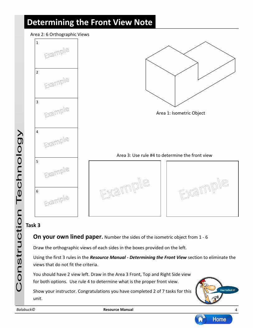
Determining the Front View Note
Task 3
On your own lined paper. Number the sides of the isometric object from 1 - 6
Draw the orthographic views of each sides in the boxes provided on the left.
Using the first 3 rules in the Resource Manual - Determining the Front View section to eliminate the
views that do not fit the criteria.
You should have 2 view left. Draw in the Area 3 Front, Top and Right Side view
for both options. Use rule 4 to determine what is the proper front view.
Show your instructor. Congratulations you have completed 2 of 7 tasks for this
unit.
Co
nstructio
n Tech
nolo
gy
Resource Manual Balabuck©
1
2
3
4
5
6
Area 3: Use rule #4 to determine the front view
Area 1: Isometric Object
Area 2: 6 Orthographic Views

5
Exemplar Rough Copy of Wood Block Task 4
On your own sheet of lined paper you will draw a rough copy. The purpose of this drawing is to
ensure that you understand the Front view and its orientation. This will also give you a chance to
demonstrate your use of the drafting tools (metric ruler and pencil).
Turn your sheet of paper in the Landscape position (holes to the top).
Draw a horizontal guideline 30 mm from the bottom and a vertical guideline 30 mm from the left.
Show your instructor this setup.
Draw the Front view 1:1 on the page (actual size). Do not trace or you will not complete this task.
Draw the Right Side view 30 mm away from the Front View, then draw the Top view 30 mm away
from the Front view.
Show your instructor. Congratulations you have completed 3 of 7
tasks for this unit.
Co
nstructio
n Tech
nolo
gy
Resource Manual Balabuck©
Guideline
Guideline

6
Centering a Drawing C
onstructio
n Tech
nolo
gy
Resource Manual Balabuck©
Horizontal Vertical
Have 255 Have 168
Need - 195 Need - 119
60 49
÷2 ÷2
30 24.5
Over from the left Up from the bottom
255 Horizontal (Have)
168
Vertical
(Have)
120 30 45
45
30
44
Horizontal
Need
Vertical
Need
Sketch the Front, Top and Right views in the proper orientation (As shown above)
On the sketch, dimension the overall measurements (length, height and width) and put 30 mm between the views.
Measure and record the actual size of the paper (255 mm x 168 mm)
This will be called what you HAVE. The HAVE will be the same for all your drawings.
Determine the NEEDS - (needs will change with every drawing) Horizontally 195 - Vertically 119
Subtract the “NEEDS” from the “HAVES” and divide by 2 to find the horizontal and vertical base lines.
Check with your instructor, then draw the base lines on your Good Copy and start the drawing.
195 119
Note: the 255 mm (horizontal)
and the 168 mm (vertical) are
the dimensions of the drawing
area available on the Good
Copy Paper

7
Lettering C
onstructio
n Tech
nolo
gy
Resource Manual Balabuck©
Task 6: The lettering used on technical drawings is called Technical lettering. This
lettering is easily read and aids the viewer in understanding complex information. The
focus of this exercise is to practice lettering, which is a writing style that is an industry
standard. Students will sharpen their ability to letter correctly and apply this to the title
block of their technical drawing.
The title block conveys all the pertinent information about the drawing such as:
The title of the object.
Who has drawn the object?
What the scale is? etc...
TECHNICAL LETTERING
A B C D E F G H I
J K L M N O P Q R
S T U V W X Y Z
TECHNICAL NUMERALS
1 2 3 4 5 6 7 8 9 0

8
Task 7: Dimensions are used to convey information about the object so that someone else
could make an exact replica or copy. For example if someone in Germany designed a new
engine for a car, a part could be made in Japan, assembled in Ontario and shipped to a
United States car dealership. This all started with Technical Drawings.
Dimension lines are used to show measurements of the object so it will be easier to build.
The trick is to put as few measurements as possible but still be understandable.
The general rules are:
Put the minimum number of dimensions (avoid cluttering your drawing)
Include overall Length, Width and Height
Include any unusual detail dimensions
Do not chain dimension across the entire object
Dimensioning (1 of 3) C
onstructio
n Tech
nolo
gy
Resource Manual Balabuck©
Length
Width
Height
Detail
Detail
9
Dimensioning (2 of 3) C
onstructio
n Tech
nolo
gy
Resource Manual Balabuck©
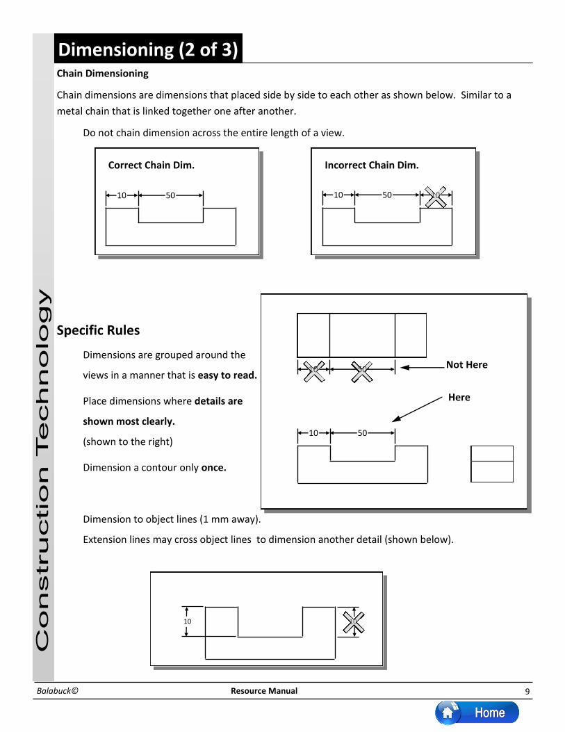
Chain Dimensioning
Chain dimensions are dimensions that placed side by side to each other as shown below. Similar to a
metal chain that is linked together one after another.
Do not chain dimension across the entire length of a view.
Specific Rules
Dimensions are grouped around the
views in a manner that is easy to read.
Place dimensions where details are
shown most clearly.
(shown to the right)
Dimension a contour only once.
Dimension to object lines (1 mm away).
Extension lines may cross object lines to dimension another detail (shown below).
Correct Chain Dim. Incorrect Chain Dim.
10 50 10
Here
Not Here 10 50
10 50
10 50
10 10

10
Specific Rules (cont.)
5 Place detail dimensions in a line (not up and down).
6. Dimension obviously identical contours only once.
Dimensioning (3 of 3)
Resource Manual Balabuck©
20
20
10
10
20 30
20 20
10
10
20 30
Your are ready for Task 6:
Dimensioning Worksheet
Co
nstructio
n Tech
nolo
gy

11
Co
nstru
ctio
n T
ech
no
log
y
Resource Manual Balabuck©
Explo
rin
g Tech
nolo
gie
s
Disk Sander
Size
Purpose
Adjustment
Parts
Safety
Determined by the diameter of the disc _____” , with 100
grit abrasive paper
To sand the end grain of wood.
No adjustments
Only use 1/2 of the disk
going down into the table
Keep the board moving
across the disc (right side)
Remove all glue and nails
Guard
Table
Power Switch

12
Co
nstru
ctio
n T
ech
no
log
y
Resource Manual Balabuck©
Parts
Safety rules concerning proper attire while operating the drill press.
Never wear loose clothing or ties around a machine. Roll up sleeves to above the elbow to
prevent getting caught in the machine
Long hair should be tied back
Never wear rings, watches, or bracelets while working in the machine shop.
Drill Press
2. Spindle
1. On/Off Button
3. Chuck
4. Table
8. Column
5. Base
6. Motor
9. Table Clamp and Handle
7. Handle
10. Chuck Key

13
Co
nstru
ctio
n T
ech
no
log
y
Keep your fingers at least 1 inch away.
When removing the wood from the machine, while still running, back out
slowly and carefully.
Do not force the wood through the machine this could will result in the
breaking of the blade.
When changing the blade, make sure that you put the new blade in the
correct way or the wood will flip up in your face.
Keep the safety guard—hold down in place.
Scroll Saw (2 of 3 Handouts)
Power Switch
Hold down
Resource Manual Balabuck©

14
Determined by the width from the blade to the arm
________” & ________”
This machine is used to cut wood in straight or curved pat-
terns
Upper guide assembly
The blade guide assembly should be moved to within 1/4”
above work
Allow machine to reach full speed before cutting
Fingers must be at least 2” away from the blade
When backing out of a cut turn the machine off, step on the
brake
Co
nstru
ctio
n T
ech
no
log
y
Band Saw
Resource Manual Balabuck©
Size
Purpose
Adjustment
Parts
Safety
Blade Guide Assembly Power Switch
Brake
Blade Guide Lock
Arm

15
Co
nstru
ctio
n T
ech
no
log
y
Compound Mitre Saw
Resource Manual Balabuck©
Size
Purpose
Adjustment
Parts
Safety
Determined by the diameter of the blade _____”
To cut wood to length and angles
The table and blade swivel 450 either way of centre.
The blade must be pressed down onto the wood.
The blade can tilt for compound angles
Never cross your hands to cut
Hands must be 3” away from blade
Long lengths of wood should be supported
For wide lumber start the blade in the lumber closest to you
and move towards the fence
6. Base
1. On/Off Switch
2. Blade
3. Fence
4.Mitre Lock
5. Mitre Indicator
16
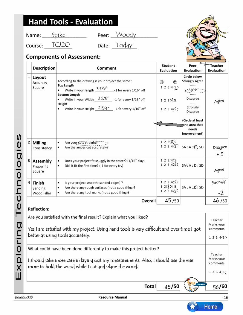
Name: ________________ Peer: _________________
Course: __________ Date: _________
Components of Assessment:
Description Comment Student
Evaluation Peer
Evaluation Teacher
Evaluation
1 Layout
Accuracy Square
According to the drawing is your project the same : Top Length
Write in your length _____ _____-1 for every 1/16” off Bottom Length
Write in your Width __________ -1 for every 1/16” off Height
Write in your Height __________ -1 for every 1/16” off
1 2 3 4 5
1 2 3 4 5
1 2 3 4 5
Circle below Strongly Agree
----- Agree -----
Disagree -----
Strongly Disagree
(Circle at least one area that
needs improvement)
2 Milling
Consistency
Are your cuts straight?
Are the angles cut accurately?
1 2 3 4 5 1 2 3 4 5
SA : A : D : SD
3 Assembly
Proper fit Square
Does your project fit snuggly in the tester? (1/16” play)
Did it fit the first time? (-1 for every try)
1 2 3 4 5 1 2 3 4 5
SA : A : D : SD
4 Finish
Sanding Wood Filler
Is your project smooth (sanded edges) ?
Are there any rough surfaces (not a good thing)?
Are there any tool marks (not a good thing)?
1 2 3 4 5 1 2 3 4 5 1 2 3 4 5
SA : A : D : SD
Overall /50 /50
Reflection:
Are you satisfied with the final result? Explain what you liked? Yes I am satisfied with my project. Using hand tools is very difficult and over time I got better at using tools accurately.
Teacher Marks your comments
1 2 3 4 5
Teacher Marks your comments
1 2 3 4 5
What could have been done differently to make this project better? I should take more care in laying out my measurements. Also, I should use the vise more to hold the wood while I cut and plane the wood.
Total /50 /60
Agree
Disagree
Strongly
Agree
Spike Woody
TCJ2O Today
+ 3
Explo
rin
g Tech
nolo
gie
s
Resource Manual Balabuck©
Hand Tools - Evaluation
-2
3 5/8”
3 5/8”
2 3/4”
45 46
45 56

17
Explo
rin
g Tech
nolo
gie
s
Resource Manual Balabuck©
West Point Bridge Designer
Getting started
Click on the Start Button and open the Technology Folder, from there click on West Point Bridge De-
signer 2013. You should see the screens below.
Click Create a New
bridge Design
Click OK

18
Explo
rin
g Tech
nolo
gie
s
Resource Manual Balabuck©
West Point Bridge Designer
Read through, then
Click Next
Check No, Click Next

19
Explo
rin
g Tech
nolo
gie
s
Resource Manual Balabuck©
West Point Bridge Designer
Click Next
Check Standard
Abutments
No Pier (One Span)
No Cable Anchorages
Medium Strength
Standard Truck
Click Next

20
Explo
rin
g Tech
nolo
gie
s
Resource Maunaul Balabuck©
West Point Bridge Designer
Select a template if
you want or select
<none> if you want
to try your own
design
Click Next
Click Next

21
Explo
rin
g Tech
nolo
gie
s
Resource Manual Balabuck©
West Point Bridge Designer
Make sure the
SPAN shows
44 meters
Click Finish
Try out the Tools,
place the member
Joints before adding
the Members

22
Explo
rin
g Tech
nolo
gie
s
Resource Manual Balabuck©
West Point Bridge Designer
Once your bridge is
finished test it out
with the truck see
below.
NOTE: You can click and
drag the mouse for
multiple selections or
hold down the Ctrl Key
and mouse click.
Port Severn Bridge, Port Severn, ON

23
Explo
rin
g Tech
nolo
gie
s
Resource Manual Balabuck©
Levers and Energy
Potential Energy
Kinetic Energy
Lever
Mechanism

24
Resource Manual Balabuck©
AND LAUNCH GLIDER
History of Aviation
irplanes are one of the newest and
fastest means of transportation.
Only spacecraft travel is faster than
airplanes. A modern jet transport plane can
carry a heavy load of passengers and
cargo across Canada in less than 5 hours.
It can fly almost a third of the way around
the world--from Vancouver to Sydney,
Australia--in about 15 hours. Passengers
can ride in comfort 30,000 to 45,000 feet
(9,100 to 13,700 meters) above the ground.
The largest jets can hold more than 400
passengers.
The activity of designing, building, and
flying aircraft is called aeronautics. During
the late 1700's, people used balloons to
make their first flights into the air. Balloons
can fly because they are lighter than air.
After the first balloon flights, inventors tried
to develop a heavier-than-air flying
machine. Some inventors experimented
with gliders (engineless planes). They
studied birds' wings and discovered that
they are curved. By giving their gliders
curved wings instead of flat ones, they
could make them fly hundreds of yards or
meters.
The Wright
uring the 1890's, Orville and
Wilbur Wright became
interested in flying while
operating their bicycle-manufacturing
shop in Dayton, Ohio. The brothers
read every book about flying they
could find. They started building
gliders in 1899. On Dec. 17, 1903,
Orville Wright became the first person
to successfully fly an engine-driven,
Mr. Balabuck© Exploring Technologies
The activity
of
designing,
building,
and flying
aircraft is
called
In 1903, the Wright brothers built their first
airplane, named the Flyer.
For further information about any of the
topics discussed in this paper, the following
resources were used:
Microsoft Encarta ‘99 Airplanes
How Stuff Works,
www.howstuffworks.com, How an

25
Resource Manual Balabuck©
ll airplanes,
except for a few
experimental
planes, have the same
basic parts. They are (1)
the wing, (2) the
fuselage (body), (3) the
tail assembly, (4) the
landing gear, and (5)
the engine. All these
parts--except the engine-
-make up a plane's
airframe. The
streamlined exterior of modern
airplanes hides a complex balance of
form and function. The fuselage
houses the pilot, passengers, and
cargo. The shape of the wings
provides the lift that enables the plane
to fly. Movable ailerons on the wings
help control lateral motions. The tail
assembly includes movable parts that
help control vertical motions and fixed
parts that increase stability during
flight. The landing gear enables the
plane to move along runways
during take-offs and
landings. Light, single-
engine planes such as this one
are popular with private pilots.
here are four basic forces
govern the flight of an airplane:
(1) gravity, (2) lift, (3) drag, and (4)
thrust. Gravity is the natural force that
pulls a plane toward the ground. Lift is
the force that pushes a plane upward
against the force of gravity. It is
created by the movement of a plane's
wing through the air. Drag is the
natural force of air opposing an
airplane's forward movement. Thrust is
the force that opposes drag and
moves a plane forward. Thrust is
created by a plane's propeller or by its
jet engines.
Anatomy of an Airplane
Wings of Flight
(1) gravity,
(2) lift,
(3) drag, and
(4) thrust.
Gravity
Thrust Drag
26
Resource Manual Balabuck©
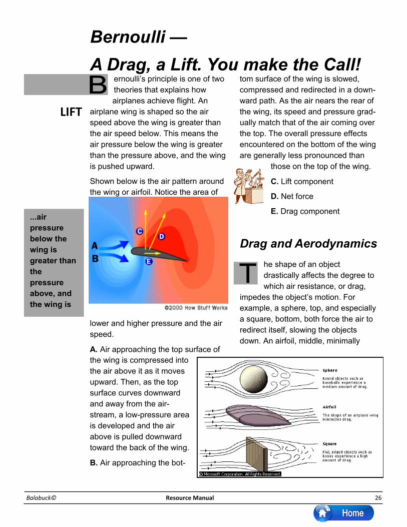
ernoulli’s principle is one of two
theories that explains how
airplanes achieve flight. An
airplane wing is shaped so the air
speed above the wing is greater than
the air speed below. This means the
air pressure below the wing is greater
than the pressure above, and the wing
is pushed upward.
Shown below is the air pattern around
the wing or airfoil. Notice the area of
lower and higher pressure and the air
speed.
A. Air approaching the top surface of
the wing is compressed into
the air above it as it moves
upward. Then, as the top
surface curves downward
and away from the air-
stream, a low-pressure area
is developed and the air
above is pulled downward
toward the back of the wing.
B. Air approaching the bot-
tom surface of the wing is slowed,
compressed and redirected in a down-
ward path. As the air nears the rear of
the wing, its speed and pressure grad-
ually match that of the air coming over
the top. The overall pressure effects
encountered on the bottom of the wing
are generally less pronounced than
those on the top of the wing.
C. Lift component
D. Net force
E. Drag component
Bernoulli —
A Drag, a Lift. You make the Call!
Drag and Aerodynamics
he shape of an object
drastically affects the degree to
which air resistance, or drag,
impedes the object’s motion. For
example, a sphere, top, and especially
a square, bottom, both force the air to
redirect itself, slowing the objects
down. An airfoil, middle, minimally
...air
pressure
below the
wing is
greater than
the
pressure
above, and
the wing is
LIFT
27
Explo
rin
g Tech
nolo
gie
s
Resource Manual Balabuck©
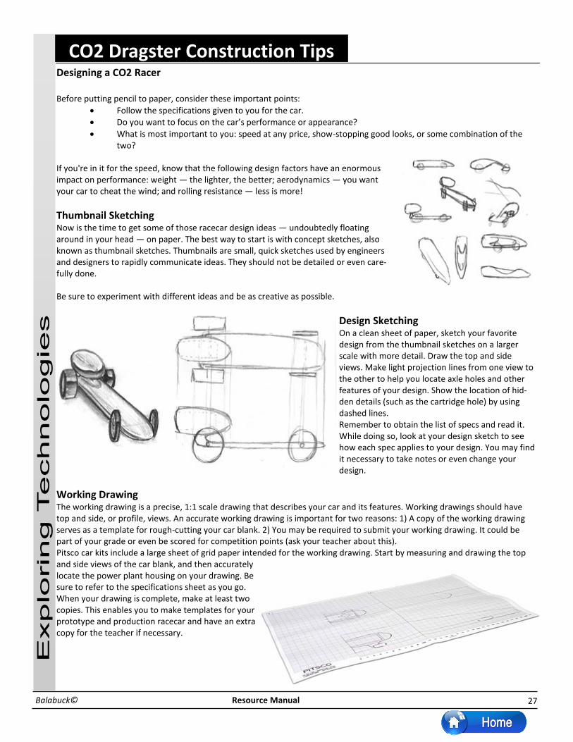
CO2 Dragster Construction Tips Designing a CO2 Racer Before putting pencil to paper, consider these important points:
Follow the specifications given to you for the car.
Do you want to focus on the car’s performance or appearance?
What is most important to you: speed at any price, show-stopping good looks, or some combination of the two?
If you're in it for the speed, know that the following design factors have an enormous impact on performance: weight — the lighter, the better; aerodynamics — you want your car to cheat the wind; and rolling resistance — less is more!
Thumbnail Sketching Now is the time to get some of those racecar design ideas — undoubtedly floating around in your head — on paper. The best way to start is with concept sketches, also known as thumbnail sketches. Thumbnails are small, quick sketches used by engineers and designers to rapidly communicate ideas. They should not be detailed or even care-fully done. Be sure to experiment with different ideas and be as creative as possible.
Design Sketching On a clean sheet of paper, sketch your favorite design from the thumbnail sketches on a larger scale with more detail. Draw the top and side views. Make light projection lines from one view to the other to help you locate axle holes and other features of your design. Show the location of hid-den details (such as the cartridge hole) by using dashed lines. Remember to obtain the list of specs and read it. While doing so, look at your design sketch to see how each spec applies to your design. You may find it necessary to take notes or even change your design.
Working Drawing The working drawing is a precise, 1:1 scale drawing that describes your car and its features. Working drawings should have top and side, or profile, views. An accurate working drawing is important for two reasons: 1) A copy of the working drawing serves as a template for rough-cutting your car blank. 2) You may be required to submit your working drawing. It could be part of your grade or even be scored for competition points (ask your teacher about this). Pitsco car kits include a large sheet of grid paper intended for the working drawing. Start by measuring and drawing the top and side views of the car blank, and then accurately locate the power plant housing on your drawing. Be sure to refer to the specifications sheet as you go. When your drawing is complete, make at least two copies. This enables you to make templates for your prototype and production racecar and have an extra copy for the teacher if necessary.

28
Explo
rin
g Tech
nolo
gie
s
Resource Manual Bal abuc
CO2 Dragster Construction Tips Prototyping Prototyping involves the construction of a three-dimensional model of your design. In this case you can use the polystyrene body blank provided in the Pitsco car kit to build your prototype. Prototyping is a quick way to put your design ideas to test. It gives designers the opportunity to make changes if necessary before the final version is produced.
Making the Prototype Cut out the top and side (profile) views from
a copy of your working drawing. Then, care-fully outline the views onto the polystyrene blank.
Use a hot wire foam cutter to roughly shape the blank:
Turn the blank on its side and cut out the profile view first.
Fit the waste pieces and working piece together and secure them by wrapping two bands of mask-ing tape around the assembly.
Set the blank assembly upright and cut out the top view. Note: The hot wire will not cut through the masking tape, so you’ll have to work around the tape. When ready, remove the tape and carefully cut those areas last.
If you haven’t already done so, remove the mask-ing tape and discard all the waste pieces.
Smooth the corners of your prototype with a sharp knife, the hot wire cutter, or sandpaper. Note: You may have limited success with sandpaper on polystyrene.
Testing the Prototype
Visual inspection – Does your prototype look like you envisioned it? Automobile manufacturers test the visual appeal of their new designs long before they put them into production.
Specifications – Meas-ure the car in appropriate places to see if it adheres to the specifica-tions.
Wind tunnel – Look for eddies around the car body. Can certain fea-tures be streamlined to reduce turbulence? Turbulence causes aerodynamic drag, which is an enemy of speed! Based on test results, you might want to modify your design. If you do, then you’ll need to make a new working drawing and, of course, make copies of it.

29
Explo
rin
g Tech
nolo
gie
s
Resource Manual Balabuck©
Testing for Tolerances This simply means to check your car against the official rules and specifications to prevent any rules violations. In most competitions, a car is disqualified if it violates even one of the rules. Conduct checks regularly during the construction of a racecar. Even in the design drawing stage, the specifications should be considered to avoid problems down the road. For TSA specs, a handy Go/No Go Gauge is available from Pitsco. It enables quick checking of several body measurements. Vehicle weight is a critical factor in competition. Because weight is an enemy of
speed, the idea is to get the weight to the absolute minimum. Remember to weigh the car with all the wheels and hardware (axles, washers, screw eyes, and so forth).
Testing for Rolling Resistance The items in this list are potential sources of rolling resistance. Be sure you test for each one.
Surface friction between two surfaces moving relative to one another – Examples include the wheels and axles, or the axles and body. Test for spinning friction by rolling your car down a ramp and observing how far the vehicle travels. Another (perhaps less scientific) method is to spin the wheels while holding the car in an inverted position and note the time that has elapsed when the wheels come to a stop. Experiment with different bearing materials or use a lubricant such adry powder graphite to improve performance.
Improper wheel alignment – This happens when axle holes are not drilled straight. (Stated more precisely, straight means the holes should be perpendicular to the car’s longitudinal axis.) Roll the car for-ward on a flat smooth surface. It should go fairly straight. If the car veers drastically to the right or left, there’s a good chance the wheels are misaligned.
Careless location of screw eyes – The guideline can actually drag on the body or wheels of the car as it moves down the track, causing a great deal of friction. Invert your car and thread an 18" length of mon-ofilament line (fishing line) through both screw eyes. Pull the line taut, and move it back and forth. If the movement of the line is restricted, consider relocating one or both of the screw eyes.
Wheel imperfections – Small imperfections from the molding process may be found on the rolling surface of a wheel. Examine your wheels and care-fully remove any imperfections with fine-grit sandpaper.
CO2 Dragster Construction Tips

30
Explo
rin
g Tech
nolo
gie
s
Resource Manual Balabuck©
Transferring Design to Body Blank Cut out the top and side (profile) views from a copy of your working drawing. Then, carefully trace the outline of the views onto the wood blank.
Drilling Axle Holes Transfer the axle hole locations onto the
blank by using a sharp pointed tool such as an awl to puncture through the template and into the wood blank.
Lay the car blank on its side and drill the axle holes. Axle holes should be drilled perpendicular to the car’s longitudinal axis in order for the car to roll freely and straight down the track. A drill press is highly recommended because it makes drilling per-pendicular holes easier.
Rough Shaping Your Car Body If you haven’t drilled the axle holes yet, do this before shaping the body. Use a band saw to roughly shape the blank:
Turn the blank on its side and cut out the profile view first.
Fit the waste pieces and working piece back together and secure
them by wrapping two bands of masking tape around the assembly.
Set the blank assembly upright and cut out the top view.
Remove the masking tape and discard all the waste pieces.
Smooth the corners of your car body. Use a bench-mounted sander, sharp knife,
wood rasp, files, or rough sandpaper (80
grit) to smooth the car to its basic rounded
shape.
Periodically check your car against the spec sheet (especially weight) to
make sure the car is still within tolerances.
When weighing your car, put the wheels,
axles, washers, screw eyes, and any other
necessary hardware on the scale along with
the body.
If your design calls for a hollowed-out body, a high-
speed rotary multi-tool works nicely. A variety of mill-
ing and sanding bits are helpful for making cavities in
the car body. Whenever using power tools to shape
the car body, go slowly and cautiously. It’s very easy
to remove too much wood and ruin your car!
CO2 Dragster Construction Tips

31
Explo
rin
g Tech
nolo
gie
s
Resource Manual Balabuck©
Fine Shaping Your Car Body At this point, your car has assumed its basic shape. Now you’re at the stage that separates the really fine cars from the mediocre cars. Extra time and ef-fort spent during the fine shaping, or pre-painting, stage have a huge payoff in the curbside appeal of the final product. Use sandpaper to remove unwant-ed bumps and irregularities from the body. Use progressively finer grit paper as you go. For example, you might start with 80-grit paper (very course, re-moves a lot of material) and progress to 220-grit (fine paper for smoothing surfaces). Check your car for symmetry, and sand the body as needed. Also, exposing your car to bright light can help reveal imperfections that need attention.
Painting Your Car Body As in the fine shaping stage, extra patience and effort put into the finishing stage can pay big dividends. Be aware that using several coats of paint can add weight to your car.
Insert a 2-foot length of 5/8" hardwood dowel into the power plant housing of the car body. This makes a very convenient handle for turning the body to paint it from all angles. Pitsco also makes a racecar paint stand for this purpose.
Use a spray can or airbrush to apply paint to the body. Spray light coats and wait several minutes between coats to allow the paint to dry.
Final Assembly: Mounting Wheels and Hardware Don’t overlook the importance of this stage. A huge factor in race performance is how smoothly the car rolls down the track. Some meticulously shaped cars have failed to finish races because of improperly installed hardware!
Gather your hardware: two axles, two straw bearings, four wheels, four washers, and two screw eyes. Depending on the configuration of the car body, different hardware might be required. Shell cars (with internal wheels) often require wheel spacers and clips to affix the axles to the car body.
Check your spec sheet for rules about wheels, axles, washers, and spacers. Carefully mount the wheels and
axles as dictated by your design. Be care-ful not to damage the fragile car body during installation.
Roll test the car on a smooth, horizontal surface. The car should roll freely, and the wheels should spin without restriction. Make adjustments if necessary.
Install the screw eyes on the underside of the car body. Im-portant: Plan the location of the screw eyes so the guideline does not rub against the car body or wheels.
Construction Tips Template Transfer Template Alternative: Use adhesive spray to attach blank-shaped templates to the top and a side of the blank. Drill and cut the blank with paper templates attached. Drilling Axle Holes Drill First: Axle holes in the body blank should be drilled before doing any shape cutting. Otherwise, it's difficult to drill straight. Rough Shaping Waste Pieces: After cutting the profile view, fit the waste pieces and body back together and secure with masking tape. This
CO2 Dragster Construction Tips

32
Explo
rin
g Tech
nolo
gie
s
Resource Manual Balabuck©
CO2 Dragster Construction Tips simplifies the cutting of the top view. Fine Shaping Haste Makes Waste: Take time and care when using power tools to shape your car body. With soft balsa wood, it's very easy to remove more material than you intended. Painting Paint Adds Weight: Applying several coats of paint can add some weight to your car. Remember to plan for this. Fill 'er Up!: Want a super smooth finish on porous balsa wood? Before painting, use a wood filler and sanding primer to fill problematic end-grain areas. Smooth Coats: Put your car under an incandescent bulb between paint coats. The warmth smoothes the surface of the paint as it dries. Finish Protection: Clear coats provide glossy protection for paint and decals, but read paint labels for compatibility infor-mation. Painting Caution: Take care when painting inside the power plant housing. Excess paint can prevent the cartridge from fitting properly. Custom Graphics: Pitsco offers an extensive selection of decals and pinstripes specially designed for CO2 racecars. Final Assembly Just a Lil' Dab: A drop of epoxy can help solidify screw eye mountings in soft balsa. But first, make sure the rules allow it. Screwy Eyes: Don’t use screw eyes that are partially open. Doing so can cause your car to detach from the guideline and slow or even damage your car. Lube 4 Speed: Heard of dry powder graphite? It's a great lubricant for axles. Sweet Wheels: Custom wheels can really accent a nice paint job and give your car a look of its own!

33
Explo
rin
g Tech
nolo
gie
s
Resource Manual Balabuck©
Measuring & Marking Tools
Tape Measure - a flexible
tape that slides into a case.
The tape has a hook on the
end that adjusts to true
zero.
Protractor - used to
measure and mark angles. I
is often used to set and
transfer bevels accurately.
Compass - for drawing circles and arcs. It can be also used to step off equal measurements.
Steel Ruler - a steel rule that is used ofr short measurements. One side is usually divided into inches, while the other is metric.
Calipers - for very accurate
measurements. Calipers are
available for outside and
inside measurements.
Sliding T-bevel - for checking
and transferring angles. The
blade pivots and can be
locked to match and angle.
Awl - used instead of a
pencil to make fine layout
lines, especially on metal. It
can also be use to make
small holes in wood for
starting drill bits, nails or
screws.
Try Square - the most
common
woodworking square
for laying out and
checking 900 angles.
Carpenter’s Square
- usually 2” x 24”
and made of metal.
This square is used
for layout lines and
squaring larger
objects.
Combination Square - used
to check layout lines at 900
and 450 angles. The handle
slides on the blade.
Speed Square (or
Rafter Angle Square -
marks out 900, 450
and other angles used
in building roofs on
houses.
Some of the definitions originate in the Wood Technology and Processes textbook.
French Curves - these plastic
curved templates allow for
variety of curved layout lines.
You can use theses curves to
make an interesting design
on your push stick.

34
Explo
rin
g Tech
nolo
gie
s
Resource Manual Balabuck©
Cutting & Shaping Tools
Claw Hammer - the
most commonly
used hammer. The
curved claw
provides leverage
for pulling nails.
Back Saw - a fine tooth
crosscut saw with a heavy
metal band across the top.
Dove Tail Saw - a small
backsaw that is used to
make fine joints. Coping Saw - has a u-
shaped frame; used to
cut curves and finishing
trim.
Hack Saw - cuts metal.
Rip Saw - cuts with the grain of the
wood.
Trigger Clamp - all
purpose clamp; only
needs one hand to
operate. Bar Clamp - large bar
clamp that is used for
gluing up wood panels.
Locking Pliers -
sometimes called Vice
Grips, the jaws can be
set and lock onto
different size objects.
Lineman’s Plier - used
mainly for twisting and
cutting wires.
Needle Nose Pliers - used
to hold small objects,
especially in electrical
work.
Side-cutting Pliers -
designed to cut wire and
thin metal
Chisels (Beveled) - used to
cut wood joints or
mortises for hinges.
Files - assorted files used
to shape and smooth
wood or metal.
Rasp - a file that
removes wood quickly,
but leaves a rough
surface.
Clamping and Cutting

35
Explo
rin
g Tech
nolo
gie
s
Resource Manual Balabuck©
Drilling Tools
Slotted Phillips Robertson
Screwdriver
Brace - bores larger holes
in wood by hand. Twist Bit - designed for
drilling holes in wood and
metal.
Forstner Bit - drills a
smooth shallow hole in
wood.
Level- used to check level
and plumb. Standard
lengths are 24” and 48”.
Drill Gauge- used to
measure drill bit sizes or
dowel.
Counter-Sink Bit & Counter-Sink with pilot hole -
drills a recess into wood to allow the head of the
screw to sit below the surface.
Other Hand Tools
Centre Punch - used to mark the
centre of holes. Also, used to mark
drilling location on metal.
Aviation Snips - used to cut thin
metal, like sheet metal or aluminum.
Utility Knife - used to cut paper,
vinyl, plastic, cardboard or thin
wood.