Resonant meta-surface superstrate for single and ... · superstrate for single and multifrequency...
12
•
Transcript of Resonant meta-surface superstrate for single and ... · superstrate for single and multifrequency...

Loughborough UniversityInstitutional Repository
Resonant meta-surfacesuperstrate for single andmultifrequency dipole
antenna arrays
This item was submitted to Loughborough University's Institutional Repositoryby the/an author.
Citation: SAENZ, E. ... et al., 2008. Resonant meta-surface superstrate forsingle and multifrequency dipole antenna arrays. IEEE Transactions on Anten-nas and Propagation, 56 (4), pp. 951 - 960
Additional Information:
• This article was published in the journal, IEEE Transactionson Antennas and Propagation [ c© IEEE], and is available at:http://dx.doi.org/10.1109/TAP.2008.919212. Personal use of this mate-rial is permitted. However, permission to reprint/republish this mate-rial for advertising or promotional purposes or for creating new collectiveworks for resale or redistribution to servers or lists, or to reuse any copy-righted component of this work in other works must be obtained from theIEEE.
Metadata Record: https://dspace.lboro.ac.uk/2134/9432
Version: Published
Publisher: c© Institute of Electrical and Electronics Engineers (IEEE)
Please cite the published version.

This item was submitted to Loughborough’s Institutional Repository (https://dspace.lboro.ac.uk/) by the author and is made available under the
following Creative Commons Licence conditions.
For the full text of this licence, please go to: http://creativecommons.org/licenses/by-nc-nd/2.5/
IEEE TRANSACTIONS ON ANTENNAS AND PROPAGATION, VOL. 56, NO. 4, APRIL 2008 951
Resonant Meta-Surface Superstrate for Single andMultifrequency Dipole Antenna Arrays
Elena Sáenz, Student Member, IEEE, Ramón Gonzalo, Member, IEEE, Iñigo Ederra,John C. Vardaxoglou, Member, IEEE, and Peter de Maagt, Fellow, IEEE
Abstract—The design of a multifrequency dipole antenna arraybased on a resonant meta-surface superstrate is proposed. The be-havior of a single element that is closely placed to a meta-surface isexperimentally investigated. The proposed meta-surface is basedon resonating unit cells formed by capacitively loaded strips andsplit ring resonators. By tuning a dipole antenna to the pass bandof the meta-surface, the physical area is effectively illuminated en-hancing the radiation performance. The gain, radiation efficiencyand effective area values of the whole configuration are comparedto the ones obtained with a single dipole without superstrate. Ra-diation efficiency values for the proposed configuration of morethan 80% and gain values of more than 4.5 1 dB are obtained.Based on this configuration, simulated results of a multifrequencyantenna array are presented. Distinctive features of this configu-ration are high isolation between elements (20 dB for a distance of0 4), and low back radiation.
Index Terms—Effective area, meta-surfaces and multifrequencyarrays, metamaterials.
I. INTRODUCTION
SINCE THE eighties, the resonance method to improve thegain of printed antennas has been well documented [1]–[3].
This method is based on the addition of a superstrate or coverlayer with either or over the substrate. By appro-priately choosing the layer thickness and the dipole position,relatively large gain may be realized. In [2], [3], the resonancegain conditions and asymptotic formulas for resonance gain,beamwidth and bandwidth (BW) were investigated. In those pa-pers gain and radiation resistance are substantially improvedover a significant BW. Nevertheless, these configurations re-quire fairly thick layers, about in the media, leading to anoverall thickness which could be incompatible with integratedcircuit antenna applications in most of the cases. Besides, theBW varies inversely with gain so that a moderate gain limit is
Manuscript received August 7, 2007; revised November 22, 2007. Thiswork was supported by the METAMORPHOSE NoE funded by the EU underContract NMP3-CT-2004-50252 and the Spanish Government under projectTEC2006-13248-C04-03/TCM.
E. Saenz, R. Gonzalo, and I. Ederra are with the Antenna Group, Public Uni-versity of Navarra, 31006 Pamplona, Spain (e-mail: [email protected]).
J. C. Vardaxoglou is with the Department of Electronic and Electrical Engi-neering, Loughborough University of Technology, Loughborough LE11 3TU,U.K. (e-mail: [email protected]).
P. de Maagt is with the European Space Research and Technology Centre(ESTEC), European Space Agency, 2200 AG Noordwijk, The Netherlands(e-mail: [email protected]).
Color versions of one or more of the figures in this paper are available onlineat http://ieeexplore.ieee.org.
Digital Object Identifier 10.1109/TAP.2008.919212
established for practical antenna operation and therefore the de-sign becomes more sensitive to the device parameters. Further-more, the aperture efficiency of those configurations is typicallyless than 60%.
Recently, several authors have proposed the application ofelectromagnetic band gap (EBG) structures [4]–[12] as super-strates in order to improve the antenna performances. Typically,an EBG array which consists of dielectric elements and charac-terized by stop/pass bands is employed as a cover for antennasto enhance the gain of a single patch antenna. The EBG actsequivalent to an aperture antenna and its effective aperture sizebecomes larger than that the original feeding antenna. The issueof thickness remains as the period of the EBG structure is closeto and more than one period is needed over the single an-tenna. However, aperture efficiencies close to 80% are obtained[11], [12]. Frequency selective surfaces (FSS) [13] based on theFabry-Perot effect [14] have also been proposed as an alterna-tive to dielectric EBGs for gain enhancement. The FSS offerssimilar transmission and reflection characteristics, but is thinnerthan the EBG configuration. However, the distance between theFSS superstrate and the ground plane of the antenna, which de-termines the resonant frequency, still needs to be about ofthe resonant frequency of the resonator.
More recent results proposed in [15]–[17] have used eitherartificial magnetic conductor (AMC) surfaces or metamaterialground planes (MPG) in combination with partially reflectivesurfaces (PRS) to design low-profile high-gain planar antennas.The overall thickness of the configuration has been reduced to
and the aperture efficiency rounds to 60%.In [18], artificial dielectrics realized as arrays of thin con-
ducting wires periodically loaded by reactive impedances (ca-pacitances) are presented. This artificial structure allows thearray period to be reduced although the wire medium is re-stricted to operation at low frequencies. The artificial lens prop-erties of this structure can in principle be electrically regulatedby controlling load reactances, with the main advantage of thepossibility to realize electrical scanning. However, if only ca-pacitively loaded wires are used in the lattice, manufacturingtolerances remain an issue of concern. This configuration hasbeen proposed to base-station antennas [18].
Recently, metamaterial (MTM) structures have shown theirbenefits as superstrate of planar antennas [19]–[22]. This paperproposes the use of meta-surfaces on top of dipole antennaarrays in order to improve their radiation performance. Fora single element, the main advantages which are derivedfrom this work are the compactness (total thickness less than
), and the high radiation efficiency (around 80%). These
0018-926X/$25.00 © 2008 IEEE
952 IEEE TRANSACTIONS ON ANTENNAS AND PROPAGATION, VOL. 56, NO. 4, APRIL 2008
meta-surfaces are based on resonant cells [23]–[25], whichexhibit pass band and stop band properties at which the poweris transmitted or reflected respectively. Due to their resonantbehavior, it is possible to design superstrates resonating at adifferent frequency resulting in low coupling between them.This fact is used to create a compact multifrequency dipoleantenna array with short distance between dipoles, less than
, and good level of isolation.The first part of this paper, Section II, is focused on an alter-
native technology of superstrates based on the use of meta-sur-faces. The unit cell selected to create the meta-surface super-strate, the manufacturing process and the resonant frequencymeasured under waveguide excitation are presented. The radi-ation performance of the superstrate while fed with a dipole isassessed in Section III. Measurements of the parameter, theresonant frequency, the gain and the radiation pattern have beencarried out for different geometrical sizes of the superstrate, i.e.,varying the number of unit cells. Using these measurements,the radiation efficiency and the effective area have been derived.Moreover, the radiation efficiency has also been obtained inde-pendently using the Wheeler cap method and compared with theone obtained by the pattern integration technique. Both resultsare in good agreement. In Section IV the main advantages of theproposed configuration are stressed and the design of a multifre-quency dipole antenna array is outlined. The work is concludedin Section V.
II. META-SURFACE DESIGN
During the recent years, several double negative materials(DNG) have been designed by different authors [23]–[25] sev-eral of them based on the topology proposed by [26], i.e., a com-bination of split ring resonators (SRRs) and wires. In order tocorrectly excite the “SRR/wire” unit cells, a plane wave withthe E-field parallel to the wires and H-field axial to the SRR isrequired, which means a propagation vector parallel to the SRRplane.
In this work, the meta-surface under study is based on theunit cell proposed by Prof. Ziolkowski in [25]. Although thisunit cell presents double negative (DNG) behavior, i.e., nega-tive refractive index, at a certain frequency band, in this paperits resonance transmission effect at the frequency band of posi-tive refractive index is used. Since the role of the DNG behavioris not exploited, the terminology meta-surface will be used. Theunit cell is constituted by a dielectric slab in which four capac-itively loaded strips (CLSs) and one SRR are embedded (seeFig. 1).
To construct the unit cell, a layer by layer technique describedin detail in [19]–[21] is followed. The material selected to fabri-cate the layers was RT/Duroid 5880, a low loss dielectric charac-terized by the parameters , loss tangent ,thickness 0.254 mm and copper cladding 70 on both faces.Three different types of layers (1, 2 and 3) were required tocreate the meta-surface unit cell. One period is constructed (seeFig. 1(b)), by stacking the layers following the pattern 123321.
The transmission and reflection properties of the manufac-tured meta-surface were tested under waveguide excitation. Amedia which consists on 12 4 unit cells in the transversal di-rections and 1 in the propagation one was placed in between two
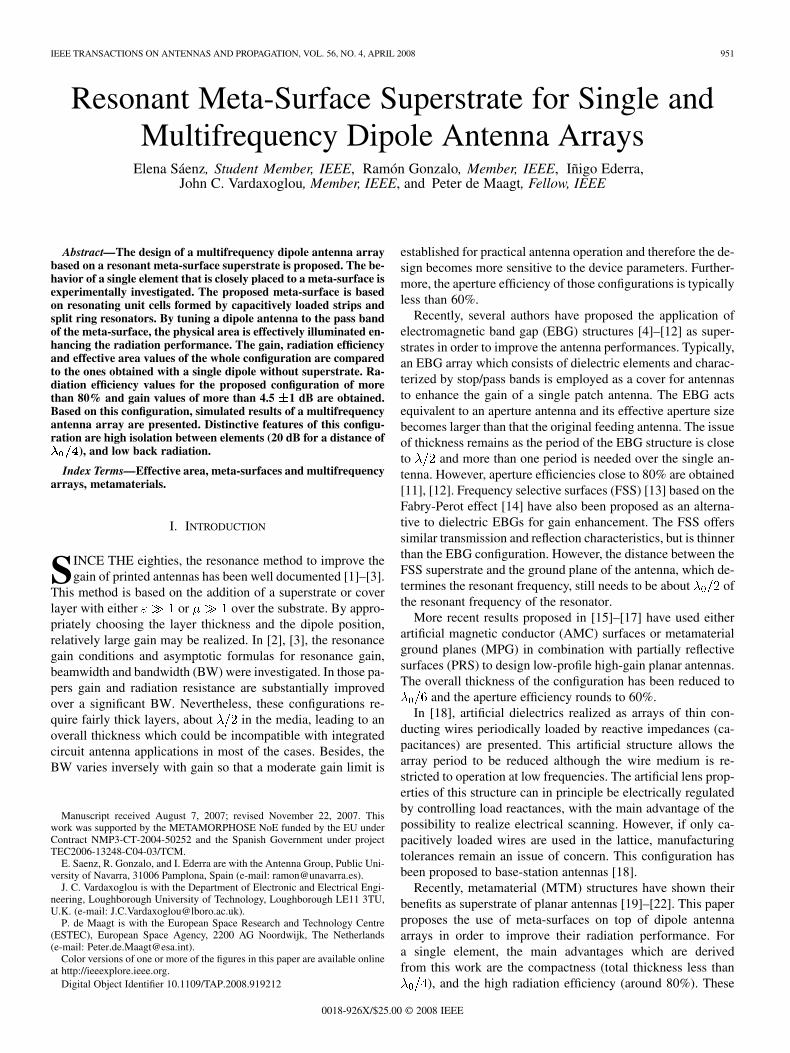
Fig. 1. Geometry of the unit cell. Width of all the gaps and lines = 0:254mm,d = 7:366 mm, d = 1:944 mm, d = 4:318 mm, l = 3:81 mm,l = 1:778 mm, l = 3:556 mm, r = 2:794 mm, r = 1:778 mm. (a)Front view. (b) Top view. The three types of layers (1, 2 and 3) are marked. (c)Cancellation of the currents in the symmetric plane.
Fig. 2. Transmission and reflection properties of the meta-surface under wave-guide excitation. Inset: set-up for the measurements; the metamaterial is placedin between the waveguides.
WR75 rectangular waveguides (19 9.5 mm) (see inset Fig. 2).The measured results are depicted in Fig. 2. Comparing theparameter between waveguides with and without the metama-terial, an enhancement of 8 dB is obtained around the resonantfrequency of 10.9 GHz.
III. RADIATION PERFORMANCE
As was mentioned before, this meta-surface is basically a res-onant structure exhibiting pass and stop bands. It is formed bya finite periodic repetition of the unit cell. The key idea behindthis configuration is to allow radiation from a primary source tospread over a larger radiating aperture. By tuning a dipole an-tenna to the pass band frequency of the superstrate, an in-phaseresonance of the unit cells will be induced leading to a more uni-form illumination of the superstrate. So, the radiating effective
SÁENZ et al.: RESONANT META-SURFACE SUPERSTRATE FOR DIPOLE ANTENNA ARRAYS 953
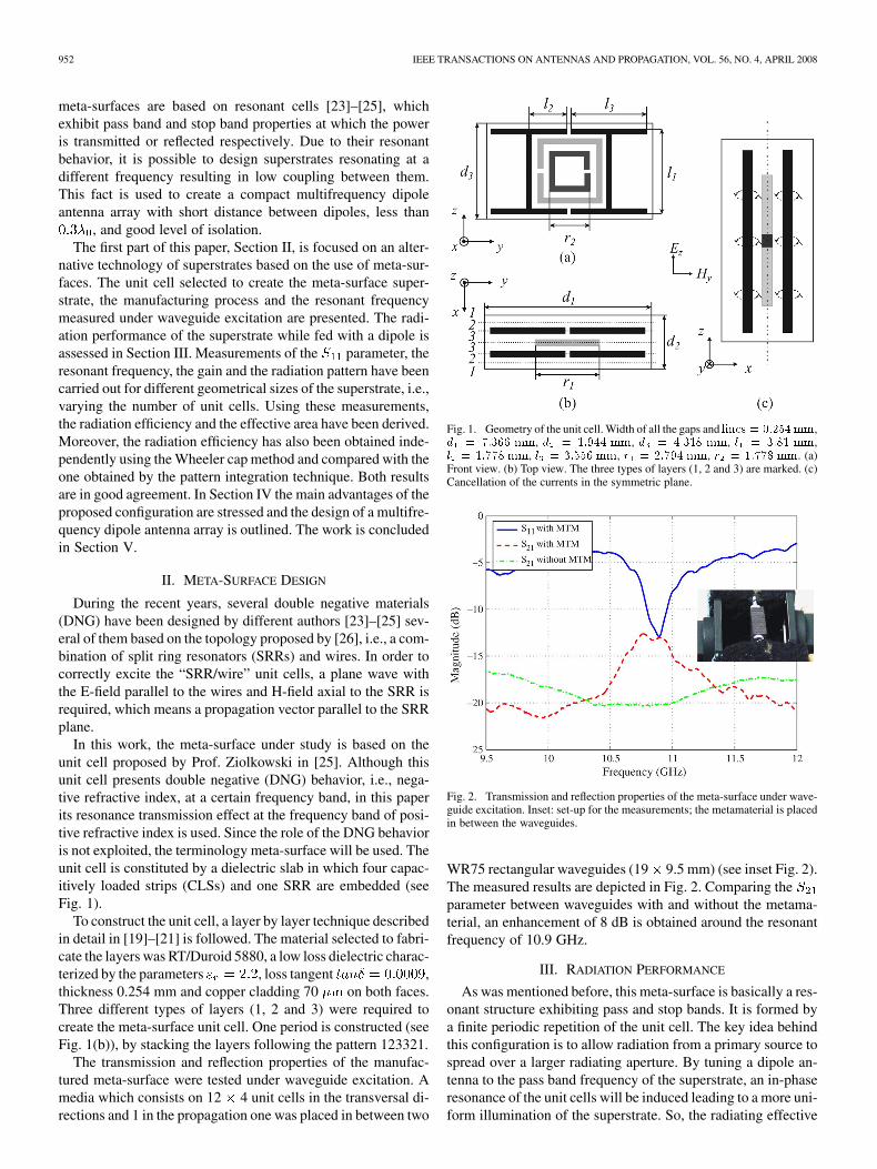
Fig. 3. Configuration of the dipole antenna with the 4� 4 uniform superstrate.Notice that electromagnetic symmetry properties were applied on the xz plane,so only half of the structure is shown. Total dimensions: l = 0:31� , l =0:58� , l = 0:25� .
area of the antenna will be enlarged. Once the meta-surface wasdesigned, it was fed by an ideal dipole antenna designed withAnsoft-HFSS. Notice that the overall configuration was opti-mized with Ansoft-HFSS to obtain the best performances; thisincludes, the distance between the dipole and the meta-surface,the length of the dipole, the number of periods of the meta-sur-face, etc.
Fig. 3 shows a sketch of the proposed dipole antenna withan uniform superstrate configuration formed by 4 4 cellsin the xy plane and 1 period in the z direction. Electromag-netic symmetry properties were applied in order to reduce thecomputational time, so only half of the structure is shown inthis figure. The thickness of the superstrate in the z directionis 7.366 mm (see Fig. 1 caption), i.e., , whereis the free space wavelength at the design resonant frequencyof 11.15 GHz. The physical orientation of the dipole withrespect to the superstrate is fixed by the requirements of anE-field parallel to the CLSs and an H-field axial to the SRRsin order to correctly excite the cells. The dimensions and po-sition of the dipole were optimized by simulating it embeddedin a dielectric slab of and loaded with the super-strate. The optimum parameters were determined by a goodmatching and gain enhancement. The final dimensions are:
,and .The dipole was fed by and ideal lumped port with an optimizedimpedance of 51.56 .
After the simulations, an experimental validation of theresults was performed. For practical reasons, a dipolewithout ground plane fed by a coaxial balun was used as feedingsource instead of the planar printed dipole. The length of thedipole was chosen according to the optimized results. Theradius of the arms was around half of the optimized planar onestaking into account the cylindrical shape. In order to estimatethe sensitivity of the configuration to small variations in thewidth and length of the dipole and the distance from the dipoleto the superstrate, a sensitivity analysis was performed. Fig. 4shows the deviation of the resonant frequency of the dipole with
Fig. 4. Deviation of the resonant frequency of the dipole with meta-surface(thick line) and without it (thin line) with respect to the optimized configurationwhen the width and length of the dipole and the distance from the dipole tothe superstrate are modified in comparison with the optimum ones: width =1:05 mm, length = 9:8 mm, distance = 0:72 mm.
Fig. 5. Set-up for the measurements of the S parameter.
and without superstrate with respect to the optimized configura-tion when the dimensions of the dipole are slightly modified. Itis observed that in the presence of the meta-surface, the systemis more stable, with a resonant frequency that remains almostconstant . In the absence of the meta-surface, forthe same variation of the physical dimensions of the dipole, thedeviation of the resonant frequency reaches 6%.
In order to determine the level of the improvements in theradiation performance due to the meta-surface, the param-eter and the radiation pattern of the dipole plus superstrate weremeasured and, by means of these results, the gain, radiation ef-ficiency and effective area were derived.
A. Parameter
The parameter of the dipole with the superstrate was mea-sured by using a network analyzer (Marconi 6210 ReflectionAnalyzer). Based on the simulation optimization process thedipole was placed just above the superstrate. The set-up for themeasurements is shown in Fig. 5.
The influence of the meta-surface in the impedance matchingof the dipole was analyzed and measured by varying the numberof periods of the superstrate in the x direction from 4 to 12.
954 IEEE TRANSACTIONS ON ANTENNAS AND PROPAGATION, VOL. 56, NO. 4, APRIL 2008
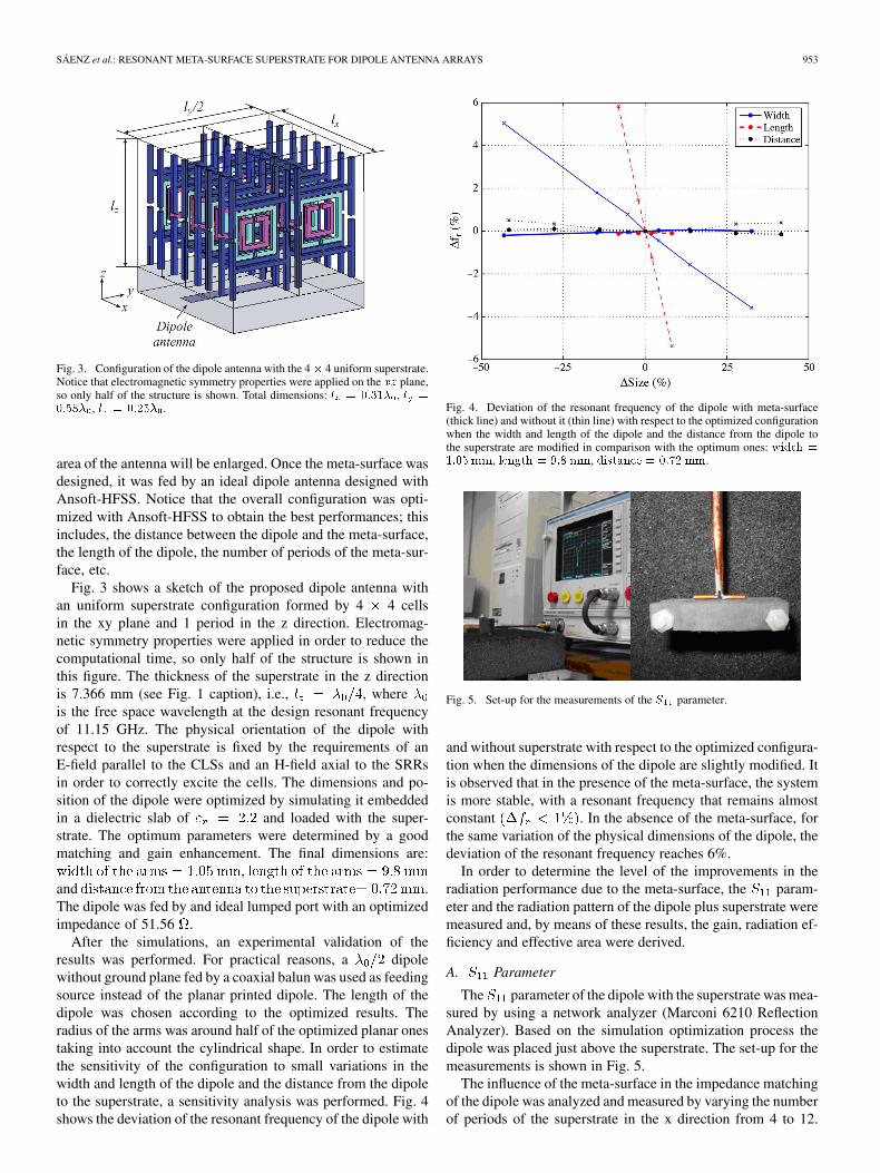
Fig. 6. Magnitude of the S parameter versus frequency as function of thenumber of cells as superstrate.
The magnitude of the parameter versus the frequency forall the measured configurations is shown in Fig. 6. As expected,an impedance matching better than 12 dB with a resonant fre-quency around 11.1 GHz and a deviation smaller than 3.5% withrespect to the central frequency has been obtained.
B. Resonant Frequency
Fig. 7 shows the dependence of the resonant frequency (min-imum ) of the configuration (meta-surface + dipole) and thefrequency of maximum gain at boresight with the number ofcells of the superstrate. The process of deriving the gain willbe explained in the next section. It can be observed that bothparameters do not exactly coincide, but there is a slight fre-quency shift between them. This is attributed to errors in themeasurements. However, a similar tendency was obtained inboth cases; as the number of cells increases, the resonant fre-quency decreases varying from 11.19 GHz in the case of 4 cellsto 10.9 GHz in the case of 12 cells [this agrees with the resultobtained with the waveguide measurements (see Fig. 2)]. Theresonant frequency curve flattens for larger superstrates sincethe meta-surface trends to behave as a more uniform media res-onating at 10.9 GHz instead of a set of single scatterers.
C. Gain
In order to characterize the different configurations in termsof absolute-gain, the two-antenna method described in [27] wasfollowed.
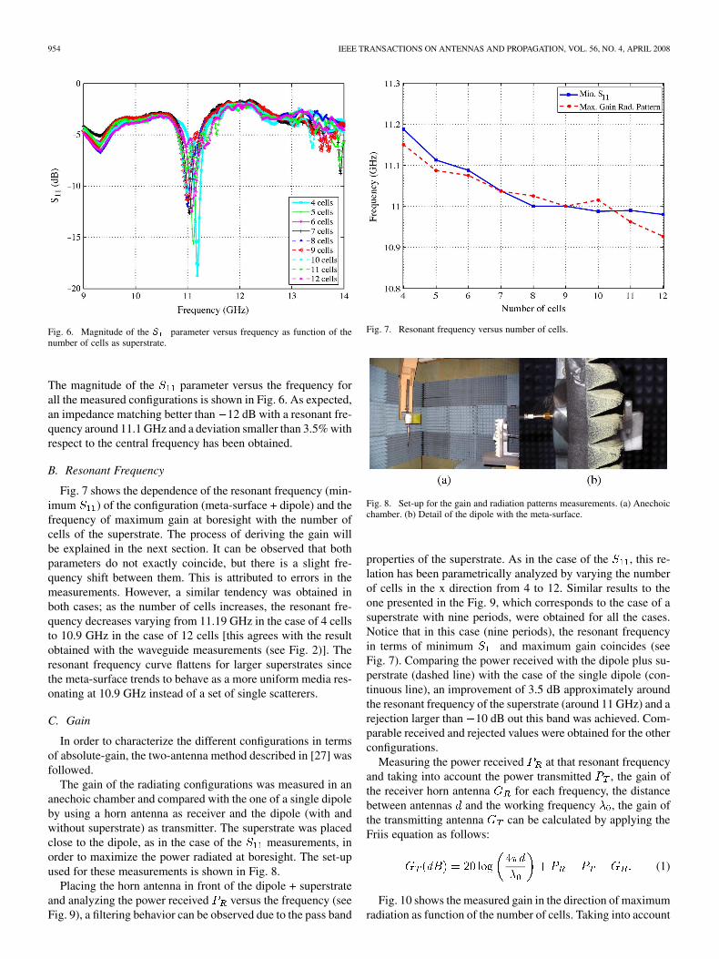
The gain of the radiating configurations was measured in ananechoic chamber and compared with the one of a single dipoleby using a horn antenna as receiver and the dipole (with andwithout superstrate) as transmitter. The superstrate was placedclose to the dipole, as in the case of the measurements, inorder to maximize the power radiated at boresight. The set-upused for these measurements is shown in Fig. 8.
Placing the horn antenna in front of the dipole + superstrateand analyzing the power received versus the frequency (seeFig. 9), a filtering behavior can be observed due to the pass band
Fig. 7. Resonant frequency versus number of cells.
Fig. 8. Set-up for the gain and radiation patterns measurements. (a) Anechoicchamber. (b) Detail of the dipole with the meta-surface.
properties of the superstrate. As in the case of the , this re-lation has been parametrically analyzed by varying the numberof cells in the x direction from 4 to 12. Similar results to theone presented in the Fig. 9, which corresponds to the case of asuperstrate with nine periods, were obtained for all the cases.Notice that in this case (nine periods), the resonant frequencyin terms of minimum and maximum gain coincides (seeFig. 7). Comparing the power received with the dipole plus su-perstrate (dashed line) with the case of the single dipole (con-tinuous line), an improvement of 3.5 dB approximately aroundthe resonant frequency of the superstrate (around 11 GHz) and arejection larger than 10 dB out this band was achieved. Com-parable received and rejected values were obtained for the otherconfigurations.
Measuring the power received at that resonant frequencyand taking into account the power transmitted , the gain ofthe receiver horn antenna for each frequency, the distancebetween antennas and the working frequency , the gain ofthe transmitting antenna can be calculated by applying theFriis equation as follows:
(1)
Fig. 10 shows the measured gain in the direction of maximumradiation as function of the number of cells. Taking into account
SÁENZ et al.: RESONANT META-SURFACE SUPERSTRATE FOR DIPOLE ANTENNA ARRAYS 955
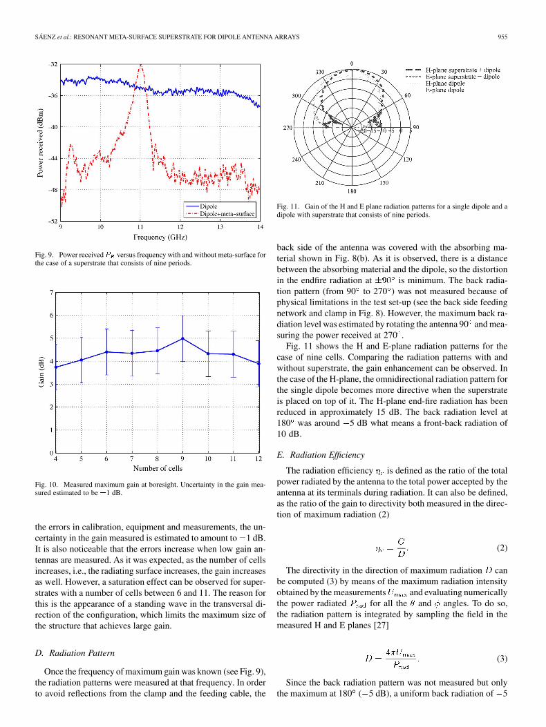
Fig. 9. Power receivedP versus frequency with and without meta-surface forthe case of a superstrate that consists of nine periods.
Fig. 10. Measured maximum gain at boresight. Uncertainty in the gain mea-sured estimated to be �1 dB.
the errors in calibration, equipment and measurements, the un-certainty in the gain measured is estimated to amount to 1 dB.It is also noticeable that the errors increase when low gain an-tennas are measured. As it was expected, as the number of cellsincreases, i.e., the radiating surface increases, the gain increasesas well. However, a saturation effect can be observed for super-strates with a number of cells between 6 and 11. The reason forthis is the appearance of a standing wave in the transversal di-rection of the configuration, which limits the maximum size ofthe structure that achieves large gain.
D. Radiation Pattern
Once the frequency of maximum gain was known (see Fig. 9),the radiation patterns were measured at that frequency. In orderto avoid reflections from the clamp and the feeding cable, the
Fig. 11. Gain of the H and E plane radiation patterns for a single dipole and adipole with superstrate that consists of nine periods.
back side of the antenna was covered with the absorbing ma-terial shown in Fig. 8(b). As it is observed, there is a distancebetween the absorbing material and the dipole, so the distortionin the endfire radiation at is minimum. The back radia-tion pattern (from 90 to 270 ) was not measured because ofphysical limitations in the test set-up (see the back side feedingnetwork and clamp in Fig. 8). However, the maximum back ra-diation level was estimated by rotating the antenna 90 and mea-suring the power received at 270 .
Fig. 11 shows the H and E-plane radiation patterns for thecase of nine cells. Comparing the radiation patterns with andwithout superstrate, the gain enhancement can be observed. Inthe case of the H-plane, the omnidirectional radiation pattern forthe single dipole becomes more directive when the superstrateis placed on top of it. The H-plane end-fire radiation has beenreduced in approximately 15 dB. The back radiation level at180 was around 5 dB what means a front-back radiation of10 dB.
E. Radiation Efficiency
The radiation efficiency is defined as the ratio of the totalpower radiated by the antenna to the total power accepted by theantenna at its terminals during radiation. It can also be defined,as the ratio of the gain to directivity both measured in the direc-tion of maximum radiation (2)
(2)
The directivity in the direction of maximum radiation canbe computed (3) by means of the maximum radiation intensityobtained by the measurements and evaluating numericallythe power radiated for all the and angles. To do so,the radiation pattern is integrated by sampling the field in themeasured H and E planes [27]
(3)
Since the back radiation pattern was not measured but onlythe maximum at 180 ( 5 dB), a uniform back radiation of 5
956 IEEE TRANSACTIONS ON ANTENNAS AND PROPAGATION, VOL. 56, NO. 4, APRIL 2008
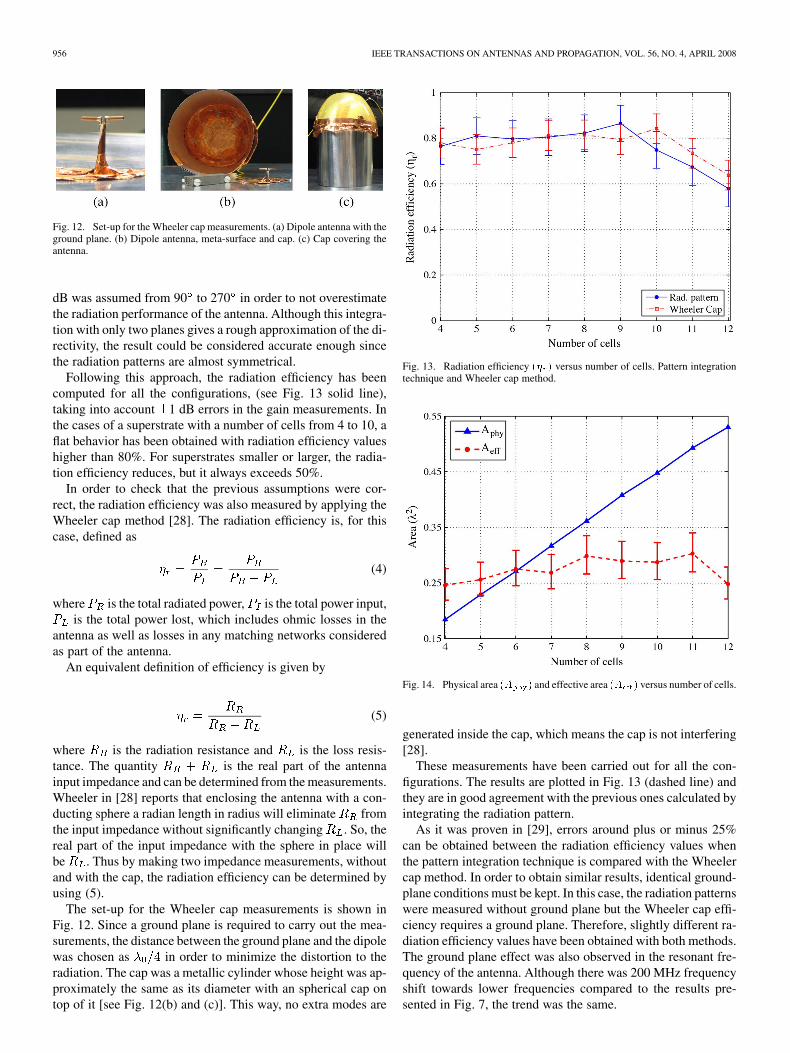
Fig. 12. Set-up for the Wheeler cap measurements. (a) Dipole antenna with theground plane. (b) Dipole antenna, meta-surface and cap. (c) Cap covering theantenna.
dB was assumed from 90 to 270 in order to not overestimatethe radiation performance of the antenna. Although this integra-tion with only two planes gives a rough approximation of the di-rectivity, the result could be considered accurate enough sincethe radiation patterns are almost symmetrical.
Following this approach, the radiation efficiency has beencomputed for all the configurations, (see Fig. 13 solid line),taking into account 1 dB errors in the gain measurements. Inthe cases of a superstrate with a number of cells from 4 to 10, aflat behavior has been obtained with radiation efficiency valueshigher than 80%. For superstrates smaller or larger, the radia-tion efficiency reduces, but it always exceeds 50%.
In order to check that the previous assumptions were cor-rect, the radiation efficiency was also measured by applying theWheeler cap method [28]. The radiation efficiency is, for thiscase, defined as
(4)
where is the total radiated power, is the total power input,is the total power lost, which includes ohmic losses in the
antenna as well as losses in any matching networks consideredas part of the antenna.
An equivalent definition of efficiency is given by
(5)
where is the radiation resistance and is the loss resis-tance. The quantity is the real part of the antennainput impedance and can be determined from the measurements.Wheeler in [28] reports that enclosing the antenna with a con-ducting sphere a radian length in radius will eliminate fromthe input impedance without significantly changing . So, thereal part of the input impedance with the sphere in place willbe . Thus by making two impedance measurements, withoutand with the cap, the radiation efficiency can be determined byusing (5).
The set-up for the Wheeler cap measurements is shown inFig. 12. Since a ground plane is required to carry out the mea-surements, the distance between the ground plane and the dipolewas chosen as in order to minimize the distortion to theradiation. The cap was a metallic cylinder whose height was ap-proximately the same as its diameter with an spherical cap ontop of it [see Fig. 12(b) and (c)]. This way, no extra modes are
Fig. 13. Radiation efficiency (� ) versus number of cells. Pattern integrationtechnique and Wheeler cap method.
Fig. 14. Physical area (A ) and effective area (A ) versus number of cells.
generated inside the cap, which means the cap is not interfering[28].
These measurements have been carried out for all the con-figurations. The results are plotted in Fig. 13 (dashed line) andthey are in good agreement with the previous ones calculated byintegrating the radiation pattern.
As it was proven in [29], errors around plus or minus 25%can be obtained between the radiation efficiency values whenthe pattern integration technique is compared with the Wheelercap method. In order to obtain similar results, identical ground-plane conditions must be kept. In this case, the radiation patternswere measured without ground plane but the Wheeler cap effi-ciency requires a ground plane. Therefore, slightly different ra-diation efficiency values have been obtained with both methods.The ground plane effect was also observed in the resonant fre-quency of the antenna. Although there was 200 MHz frequencyshift towards lower frequencies compared to the results pre-sented in Fig. 7, the trend was the same.

SÁENZ et al.: RESONANT META-SURFACE SUPERSTRATE FOR DIPOLE ANTENNA ARRAYS 957
Fig. 15. Superstrate with four cells. Notice that periodic boundary conditionswere applied on the xz and yz planes, so only one forth of the structure is shown.(a) E field on the H plane of the dipole (xz) at the resonant frequency 10.8 GHz.(b) Poynting vector on the radiating surface at the resonant frequency.
Using the single dipole as reference case, the radiation effi-ciencies obtained were 0.86 and 0.73 with the pattern integrationtechnique and Wheeler cap method respectively. That means anerror of around 17% between the two methods, what is withinexpectations.
F. Effective Area
Once the maximum directivity at boresight of the config-uration is obtained, the effective area of the meta-surfacecan be calculated by applying (6)
(6)
Fig. 14 shows a comparison between the effective area derivedfrom the measurements (taking into account the errors inthe measurements of the gain) and the physical area of themeta-surface. When the superstrate is small (4 unit cells;equal to ), it can be observed that the effective area islarger than the physical one. This is an artefact effect producedby the mathematical definition of the effective area when theradiating surface is not wide enough and there are not metallicwalls surrounding the antenna. This is a known phenomenadescribed by Balanis for dipole antennas [27] p. 83. This effectcan be explained through the observation of the fringing fieldson the edges of the structure (see Fig. 15). However, for largersuperstrates (from five to eight cells), the effective area issimilar to the physical one, what means that the meta-surfaceis completely illuminated, i.e., a uniform illumination has beenachieved. On the other hand, when the meta-surface becomesvery large, the single dipole cannot excite and illuminate thewhole superstrate and therefore the effective area becomessmaller than the physical one. In fact, from Fig. 14, it can beobserved that the maximum area that the single dipole canilluminate is around .
Plotting the E field on the H plane of the dipole at the resonantfrequency and the Poynting vector on the radiating surface ofthe superstrate (see Fig. 15) the uniform illumination and theextension beyond the physical geometry of the radiated field canbe observed, which is confirming the previous explanation foran effective area larger than the physical one.
Fig. 16. Geometry of the MFAA. Notice that electromagnetic symmetry prop-erties were applied on the xz plane, so only half of the structure is shown.Dipoles 1 and 3 are radiating at the LRF and dipole 2 at HRF. (a) Front view.(b) Top view.
IV. MULTIFREQUENCY ANTENNA CONFIGURATION
The results obtained in the previous sections show that thephysical area of the proposed structure can be used very effec-tively in order to enhance the radiation performance of planarantennas due to the uniform illumination of the superstrate.Other advantages of the configuration are the compactness( ), the quite symmetrical E andH-plane radiation patterns and reduced back radiation.
On the other hand, it has been observed that the unit cells arehighly resonating and the field is confined on the superstrate. Al-though some fringing fields can appear at the edges of the struc-ture, it is possible to place the same type of unit cell but with adifferent resonant frequency (same shape but different size) onboth sides. In this case both unit cells will be resonating inde-pendently. By tuning two dipoles to the corresponding resonantfrequency of each group of cells, a multifrequency antenna array(MFAA) can be designed with low coupling between elements.
In order to implement it, the unit cell explained in Section IIhas been scaled to be working at a higher frequency, around12.5 GHz. By combining superstrates consisting of low resonantfrequency (LRF) unit cells and high resonant frequency (HRF)ones, and tuning dipoles to these frequencies, the MFAA is de-signed. The MFAA studied is schematically depicted in Fig. 16.
The dipoles 1 are 3 are tuned to the LRF and the dipole 2 tothe HRF. Due to the small dimensions of the cells, the dipolesare very close to each other ( at LRF; at HRF).This potentially will allow to design compact multifrequencyantennas.
By plotting the magnitude of the E-field on the H-plane of thedipoles, the low coupling between dipoles can be easily under-stood. When the dipoles 1 are 3 are fed [see Fig. 17(a)] the groupof cells that are above them confine the power. However, theHRF cells that are in between are reflecting the power becausethey are not resonating, reducing at the same time the coupling

958 IEEE TRANSACTIONS ON ANTENNAS AND PROPAGATION, VOL. 56, NO. 4, APRIL 2008
Fig. 17. Magnitude of the E field on the H-plane of the dipoles (xz plane). (a)Dipoles 1 and 3 are radiating at 10.8 GHz. (b) Dipole 2 is radiating at 12.55GHz.
between dipoles. When the dipole 2 is active, the opposite ef-fect occurs. Only the HRF cells transmit the power and the LRFones that are on both sides reflect it [see Fig. 17(b)]. For dis-tance between dipoles around 0.25 , coupling values of 20dB have been obtained.
Plotting the H and E-plane radiation patterns (see Fig. 18), theimproved performance of this MFAA can be observed. Due to therather uniform illumination of the radiation surface (see Fig. 17),gain and aperture efficiency enhancement is obtained, keepingthe low back radiation and symmetrical radiation patterns.
V. CONCLUSION
In this paper, a novel implementation to enhance the radi-ation performances of a dipole antenna based on the use ofmeta-surfaces as superstrate has been presented. A finite uni-form meta-surface has been characterized in terms of pa-rameter, gain, radiation pattern, radiation efficiency and effec-tive area. Measurements of different configurations have provenan enhancement of the gain at boresight of about 3.5 1 dB witha reduction of the H-plane endfire radiation of about 15 dB. Theradiation efficiency has been calculated by means of the patternintegration technique and Wheeler cap method with efficiencyvalues higher than 80%. For superstrates up to eight cells, the ef-fective area was similar to the physical one, what means a uni-form illumination of the meta-surface. For larger superstrates,the effective area does not increase since the maximum areathat the dipole can illuminate has been estimated around .Based on this configuration, a compact multifrequency antennaarray has been simulated, showing the gain enhancement andlow coupling between elements.
ACKNOWLEDGMENT
The authors would like to thank Prof. R. W. Ziolkowski forhis helpful discussions on various aspects of this work andthe support of the Wireless Communication Research Group
Fig. 18. H and E-plane radiation patterns (a) Dipoles 1 and 3 are radiating at10.8 GHz. (b) Dipole 2 is radiating at 12.55 GHz.
(WiCR) of Loughborough University for their assistance withthe measurements.
REFERENCES
[1] Y. Sugio, T. Makimoto, S. Nishimura, and H. Nakanishi, “Analysisfor gain enhancement of multiple-reflection line antenna with dielectricplates,” Trans. IECE, pp. 80–112, Jan. 1981.
[2] N. G. Alexopoulos and D. R. Jackson, “Fundamental superstrate(cover) effects on printed circuit antennas,” IEEE Trans. AntennasPropag., vol. 32, pp. 807–815, Aug. 1984.
[3] D. R. Jackson and N. G. Alexopoulos, “Gain enhancement methods forprinted circuit antennas,” IEEE Trans. Antennas Propag., vol. 33, pp.976–987, Sep. 1985.
[4] Y. J. Lee, J. Yeo, R. Mittra, and W. S. Park, “Application of electro-magnetic bandgap (EBG) superstrates with controllable defects for aclass of patch antennas as spatial angular filters,” IEEE Trans. AntennasPropag., vol. 53, pp. 224–235, Jan. 2005.
[5] L. Zhang, H. Contopanagos, N. G. Alexopoulos, and E. Yablonovitch,“An electromagnetic bandgap resonator antenna,” in Proc. IEEE An-tennas Propagation Society Int. Symp., Jun. 21–26, 1998, vol. 1, pp.186–189.
[6] L. Zhang, N. G. Alexopoulos, and E. Yablonovitch, “Microstrip linefed slot antenna with pbg superstrate,” in Proc. IEEE Antennas Propa-gation Society Int. Symp., Jul. 11–16, 1999, vol. 3, pp. 1924–1927.
[7] C. Cheype, C. Serier, M. Thevenot, T. Monediere, A. Reineix, and B.Jecko, “An electromagnetic bandgap resonator antenna,” IEEE Trans.Antennas Propag., vol. 50, pp. 1285–1290, Sep. 2002.
[8] M. Thevenot, C. Cheype, A. Reineix, and B. Jecko, “Directive pho-tonic-bandgap antennas,” IEEE Trans. Microw. Theory Tech., vol. 47,no. 11, pp. 2115–2122, 1999.
SÁENZ et al.: RESONANT META-SURFACE SUPERSTRATE FOR DIPOLE ANTENNA ARRAYS 959
[9] B. Temelkuran, M. Bayindir, E. Ozbay, R. Biswas, M. M. Sigalas, G.Tuttle, and K. M. Ho, “Photonic crystal-based resonant antenna with avery high directivity,” J. Appl. Phys., vol. 87, no. 1, pp. 603–605, 2000.
[10] R. Biswas, E. Ozbay, B. Temelkuran, M. Bayindir, M. M. Sigalas, andK.-M. Ho, “Exceptionally directional sources with photonic-bandgapcrystals,” J. Opt. Soc. Am. B, vol. 18, no. 11, pp. 1684–1688, 2001.
[11] L. Leger, C. Serier, R. Chantalat, M. Thevenot, T. Monediere, andB. Jecko, “1D dielectric EBG resonator antenna design,” in Ann.Telecommun. Tome 49, Mar.–Apr. 2004, pp. 242–260.
[12] A. Neto, N. Llombart, G. Gerini, M. D. Bonnedal, and P. de Maagt,“EBG enhanced feeds for the improvement of the aperture efficiencyof reflector antennas,” IEEE Trans. Microw. Theory Tech., vol. 55, no.8, pp. 2185–2193, 2007.
[13] Y. J. Lee, J. Yeo, R. Mittra, and W. S. Park, “Design of a high-direc-tivity electromagnetic band gap (EBG) resonator antenna using a fre-quency-selective surface (FSS) superstrate,” Microw. Opt. Tech. Lett.,vol. 43, pp. 462–467, Dec. 2004.
[14] R. Sauleau, Fabry-Perot Resonators, Encyclopedia of RF and Mi-crowave Engineering. New York: Wiley, 2005.
[15] A. P. Feresidis, G. Goussetis, S. Wang, and J. C. Vardaxoglou, “Arti-ficial magnetic conductor surfaces and their application to low-profilehigh-gain planar antennas,” IEEE Trans. Antennas Propag., vol. 53, pp.209–215, Jan. 2005.
[16] A. P. Feresidis and J. C. Vardaxoglou, “High gain planar antenna usingoptimized partially reflective surfaces,” Proc. Inst. Elect. Eng. Microw.Antennas Propag., vol. 148, no. 6, pp. 345–350, 2001.
[17] S. Wang, A. P. Feresidis, G. Goussetis, and J. C. Vardaxoglou, “High-gain subwavelength resonant cavity antennas based on metamaterialground planes,” in Proc. Inst. Elect. Eng. Microw. Antennas Propag.,Feb. 2006, vol. 153, pp. 1–6.
[18] P. Ikonen, C. Simovski, and S. Tretyakov, “Compact directive antennaswith a wire-medium artificial lens,” Microw. Opt. Tech. Lett., vol. 43,pp. 467–469, Dec. 2004.
[19] E. Saenz, R. Gonzalo, I. Ederra, and P. de Maagt, “High efficient dipoleantennas by using left-handed superstrates,” in Proc. 13th Int. Symp.Antennas JINA, Nov. 2004, pp. 112–118.
[20] E. Saenz, R. Gonzalo, I. Ederra, and P. de Maagt, “Transmission en-hancement between rectangular waveguides by means of a left handedmedia,” Elect. Lett., vol. 41, pp. 725–727, Jun. 2005.
[21] E. Saenz, R. Gonzalo, I. Ederra, and P. de Maagt, “Application of lefthanded superstrates to improve radiation performances of dipole an-tennas,” in Proc. Eur. Microw. Association, Mar. 2006, vol. 2, pp. 3–11.
[22] E. Saenz, I. Ederra, P. de Maagt, and R. Gonzalo, “High efficient dipoleantenna with a planar meta-surface,” Elect. Lett., vol. 43, no. 16, Aug.2007.
[23] D. R. Smith, W. J. Padilla, D. C. Vier, S. C. Nemat-Nasser, and S.Schultz, “Composite medium with simultaneously negative perme-ability and permittivity,” Phys. Rev Lett., vol. 84, pp. 4184–4187, May2000.
[24] R. A. Shelby, D. R. Smith, and S. Schultz, “Experimental verificationof a negative index of refraction,” Science, vol. 292, pp. 77–79, Apr.2001.
[25] R. W. Ziolkowski, “Design, fabrication, and testing of double neg-ative metamaterials,” IEEE Trans. Antennas Propag., vol. 51, pp.1516–1529, Jul. 2003.
[26] J. B. Pendry, “Negative refraction makes a perfect lens,” Phys. RevLett., vol. 85, pp. 3966–3969, Oct. 2000.
[27] C. A. Balanis, Antenna Theory: Analysis and Design, 2nd ed. NewYork: Wiley, 1997.
[28] H. A. Wheeler, “The radiansphere around a small antenna,” in Proc.IRE, Aug. 1959, pp. 1325–1331.
[29] E. H. Newman, P. Bohley, and C. H. Walter, “Two methods for themeasurement of antenna efficiency,” IEEE Trans. Antennas Propag.,vol. 23, pp. 457–461, July 1975.
Elena Sáenz (S’04) was born in Viana, Navarra,Spain, in 1981. She received the M.Sc. degree intelecommunication engineering from the PublicUniversity of Navarra (UPNa), Navarra, Spain, in2004, where she is currently working toward thePh.D. degree.
Her doctoral research is focused on the analysisand design of metasurfaces with emphasis on theirapplication as superstrates for antennas.
Ramón Gonzalo (S’95–M’04) was born on July 15,1972 in Logroño, La Rioja. He received the M.Sc.and the Ph.D. degrees in “Ingeniero de Telecomuni-cación” (both with honors) from the Public Univer-sity of Navarra (UPNa), Spain.
Since October 1995, he has been with the An-tennas Group, Electrical and Electronic EngineeringDepartment, UPNa where he is currently an Asso-ciate Professor. From September 1997 to December1998, he was a Research Fellow to the AntennaSection in ESA-ESTEC where he was involved in
the modeling and design of electromagnetic crystal devices at microwave andmillimeter wave frequencies. He has been involved in more than 15 researchprojects, acting as Coordinator in several of them. In particular he has beenCoordinator of two electromagnetic crystal projects within the framework ofESTEC contracts. He has more than 20 journal publications and 80 conferencepapers related to electromagnetic crystal topics. His current area of researchis in the field of electromagnetic crystal structures with emphasis on spaceantenna applications, design of waveguide transmission lines and corrugatedhorn antennas.
Iñigo Ederra was born in Isaba, Navarra, Spain in1972. He received the M.Sc. degree in telecommuni-cation engineering from the Universidad Pùblica deNavarra, Navarra, Spain, in 1996 and the Ph.D. de-gree in telecommunication engineering from the Uni-versidad Pùblica de Navarra, Navarra, Spain, in 2004.
In 1997, he joined the Microwave and MillimetreWave Group, Universidad Pùblica de Navarra,where he was involved in the study of high-powermillimeter-wave components. From 1999 to 2000,he was with the European Space Research and
Technology Centre (ESTEC), ESA, Noordwijk, The Netherlands, where hewas working on electromagnetic bandgap materials and their applications inthe field of antennas. Since 2001, he is with the Antenna Group, UniversidadPùblica de Navarra.
His research interests are in the field of electromagnetic bandgap materialsand metamaterials and their applications in microwave and millimeter wavecomponents and antennas.
John (Yiannis) C. Vardaxoglou (M’87) received theB.Sc. degree in mathematics (mathematical physics)and the Ph.D. degree from the University of Kent atCanterbury, U.K., in 1981 and 1985, respectively.
In January 1988, he was appointed a Lecturer inCommunications with the Department of Electronicand Electrical Engineering, Loughborough Univer-sity of Technology, Loughborough, U.K. He was pro-moted to the position of Senior Lecturer in January1992. In 1998, he was appointed Professor of Wire-less Communications. He holds the Chair of Wireless
Communications at Loughborough University and is the Founder of the Centrefor Mobile Communications Research (CMCR). He established the WirelessCommunications Research (WiCR) group at Loughborough University and heHeads the Centre for Mobile Communications Research. He has pioneered re-search, design and development of frequency selective surfaces (FSS) for com-munication systems and has commercially exploited a number of his innova-tions. He has been active in the analysis and design of small low specific ab-sorption rate (SAR) material loaded antennas for mobile telephony and elec-tromagnetic band gap (EBG) structures for subsystem applications. His cur-rent research interests include array antennas, FSS, radomes, leaky wave res-onant antennas, optical control of microwaves and devices, periodic surfacesand EBG/AMC/LH materials, and material-loaded mobile telephone antennas.He has served as a consultant to various industries, holds three patents and is theTechnical Director of Antrum, Ltd. He has published over 130 refereed journalsand conference proceeding papers and has written a book on FSS.
Dr Vardaxoglou is currently the Chairman of the Executive Committee ofthe Antennas and Propagation Professional Network of the Institution of Engi-neering and Technology (IET), London, U.K., and he Chairs the IEEE’s Dis-tinguish Lecturer Program of the Antennas and Propagation Society. He Chairsthe Executive Committee of Metamorphose, EU FP6 Network of Excellenceof Metamaterials. He chaired the 1st and 2nd Institution of Electrical Engi-

960 IEEE TRANSACTIONS ON ANTENNAS AND PROPAGATION, VOL. 56, NO. 4, APRIL 2008
neers’s (IEE) Antenna Measurements and SAR (AMS’02 and AMS’04) Con-ferences and has been on the organizing committee of the 2001 and 2003 IEEInternational Conferences on Antennas and Propagation. He was the GeneralChair of the 1st and 2nd Loughborough Antennas and Propagation Conference(LAPC’05).
Peter de Maagt (S’88–M’88–SM’02–F’07) wasborn in Pauluspolder, The Netherlands, in 1964.He received the M.Sc. and Ph.D. degrees fromEindhoven University of Technology, Eindhoven,The Netherlands, in 1988 and 1992, respectively,both in electrical engineering.
He is currently with the European Space Re-search and Technology Centre (ESTEC), EuropeanSpace Agency, Noordwijk, the Netherlands. Hisresearch interests are in the area of millimeter andsubmillimeter-wave reflector and planar integrated
antennas, quasi-optics, electromagnetic bandgap antennas, and millimeter- andsub-millimeter-wave components.
Dr. de Maagt was co-recipient of the H. A. Wheeler Award of the IEEE An-tennas and Propagation Society for the Best Applications Paper of the year 2001.He was granted a European Space Agency Award for Innovation in 2002. Hewas corecipient of the Loughborough Antennas and Propagation Conference(LAPC) 2006 and the International Workshop on Antenna Technology (IWAT)2007 Best Paper Award.