Resonance Propagation and Mitigation in Grid … · Resonance Propagation and Mitigation in Grid...
10
Page 1923 Resonance Propagation and Mitigation in Grid Connected and Islanding Micro Grids by Using Fuzzy Logic K. Hari Prasada Reddy PG Student, Department of Electrical and Electronics Engineering, MLEC, JNTUK University, Singarayakonda, Andhra Pradesh, India. Y.Ramaiah Associate Professor Department of Electrical and Electronics Engineering, MLEC, JNTUK University, Singarayakonda, Andhra Pradesh, India. ABSTRACT In this paper, a micro grid resonance propagation model is investigated. To actively mitigate the resonance using DG units, an enhanced DG unit control scheme that uses the concept of virtual impedance is proposed. It can be seen that a conventional voltage-controlled dg unit with an LC filter has a short-circuit feature at the chosen harmonic frequencies, whereas a current-controlled dg unit presents an open-circuit characteristic. Because of completely different behaviors at harmonic frequencies, specific harmonic mitigation methods shall be developed for current controlled and voltage-controlled dg units, respectively. The application of underground cables and shunt capacitor banks may introduce power distribution system resonances. This paper additionally focuses on developing a voltage-controlled dg unit based active harmonic damping technique for grid connected and islanding micro grid systems. An improved virtual impedance control method with a virtual damping resistor and a nonlinear virtual capacitor is proposed. The nonlinear virtual capacitor is used to compensate the harmonic dip on the grid-side inductor of a dg unit LCL filter. Here we are using fuzzy controller compared to other controller due to its accurate performance. The virtual resistance is principally answerable for micro grid resonance damping. The effectiveness of the proposed damping method is examined using each a single dg unit and multiple parallel dg units. Index Terms—Active power filter, distributed power generation, droop control, grid-connected converter, micro grid, power quality, renewable energy system, resonance propagation, virtual impedance. I INTRODUCTION The increasing application of nonlinear loads cans led to significant harmonic pollution in a power distribution system. The harmonic distortion might excite complicated resonances, particularly in power systems with underground cables or subsea cables and. In fact, these cables with nontrivial parasite shunt capacitance will form an LC ladder network to amplify resonances. in order to mitigate system resonances, damping resistors or passive filters can be placed in the distribution networks .however, the mitigation of resonance propagation exploitation passive components is subject to some well understood problems, like power loss and additional investment. Moreover, a passive filter might even bring extra resonances if it's designed or installed without knowing detailed system configurations. To avoid the adoption of passive damping equipment, numerous types of active damping methods are developed. Among them, the resistive active power filter (R-APF) is often considered as a promising way to understand better performance. Conventionally, the principle of R- APF is to emulate the behavior of passive damping resistors by applying closed-loop current-controlled method (CCM) to power electronics converters. in this management category, the R-APF will be simply modeled as virtual harmonic resistor if it's viewed at the distribution system level. in addition, many changed-APF ideas were additionally developed in the recent literature. In, the separate tuning method was proposed to regulate damping resistances at different harmonic orders. Accordingly, the R-APF basically works as a non linear resistor. In, the operation of multiple Ripsaws also considered, where an interesting
-
Upload
nguyendiep -
Category
Documents
-
view
227 -
download
2
Transcript of Resonance Propagation and Mitigation in Grid … · Resonance Propagation and Mitigation in Grid...

Page 1923
Resonance Propagation and Mitigation in Grid Connected and
Islanding Micro Grids by Using Fuzzy Logic
K. Hari Prasada Reddy
PG Student,
Department of Electrical and Electronics Engineering,
MLEC, JNTUK University,
Singarayakonda, Andhra Pradesh, India.
Y.Ramaiah
Associate Professor
Department of Electrical and Electronics Engineering,
MLEC, JNTUK University,
Singarayakonda, Andhra Pradesh, India.
ABSTRACT
In this paper, a micro grid resonance propagation
model is investigated. To actively mitigate the
resonance using DG units, an enhanced DG unit
control scheme that uses the concept of virtual
impedance is proposed. It can be seen that a
conventional voltage-controlled dg unit with an LC
filter has a short-circuit feature at the chosen
harmonic frequencies, whereas a current-controlled
dg unit presents an open-circuit characteristic.
Because of completely different behaviors at
harmonic frequencies, specific harmonic mitigation
methods shall be developed for current controlled
and voltage-controlled dg units, respectively. The
application of underground cables and shunt
capacitor banks may introduce power distribution
system resonances. This paper additionally focuses
on developing a voltage-controlled dg unit based
active harmonic damping technique for grid
connected and islanding micro grid systems. An
improved virtual impedance control method with a
virtual damping resistor and a nonlinear virtual
capacitor is proposed. The nonlinear virtual
capacitor is used to compensate the harmonic dip on
the grid-side inductor of a dg unit LCL filter. Here
we are using fuzzy controller compared to other
controller due to its accurate performance. The
virtual resistance is principally answerable for micro
grid resonance damping. The effectiveness of the
proposed damping method is examined using each a
single dg unit and multiple parallel dg units. Index
Terms—Active power filter, distributed power
generation, droop control, grid-connected converter,
micro grid, power quality, renewable energy system,
resonance propagation, virtual impedance.
I INTRODUCTION
The increasing application of nonlinear loads cans led
to significant harmonic pollution in a power
distribution system. The harmonic distortion might
excite complicated resonances, particularly in power
systems with underground cables or subsea cables and.
In fact, these cables with nontrivial parasite shunt
capacitance will form an LC ladder network to amplify
resonances. in order to mitigate system resonances,
damping resistors or passive filters can be placed in the
distribution networks .however, the mitigation of
resonance propagation exploitation passive
components is subject to some well understood
problems, like power loss and additional investment.
Moreover, a passive filter might even bring extra
resonances if it's designed or installed without
knowing detailed system configurations. To avoid the
adoption of passive damping equipment, numerous
types of active damping methods are developed.
Among them, the resistive active power filter (R-APF)
is often considered as a promising way to understand
better performance. Conventionally, the principle of R-
APF is to emulate the behavior of passive damping
resistors by applying closed-loop current-controlled
method (CCM) to power electronics converters. in this
management category, the R-APF will be simply
modeled as virtual harmonic resistor if it's viewed at
the distribution system level. in addition, many
changed-APF ideas were additionally developed in the
recent literature. In, the separate tuning method was
proposed to regulate damping resistances at different
harmonic orders. Accordingly, the R-APF basically
works as a non linear resistor. In, the operation of
multiple Ripsaws also considered, where an interesting
Page 1924
droop control was designed to offer autonomous
harmonic power sharing ability among parallel
RAPFs.On the other hand, renewable energy
source(RES) based distributed generation (DG) units
are adopted to form flexible micro grids and their
interfacing converters even have the chance to address
different distribution system power quality problems.
Fig. 1. Simplified one-line diagram of a single-phase
Micro grid. Service. Simulated results are provided
to confirm the validity of the proposed Method.
For current-controlled dg units, the auxiliary R-APF
function can be seamlessly incorporated into the
primary dg real power injection function by modifying
the current reference. However, conventional CCM
will hardly provide direct voltage support throughout
micro grid islanding operation. To beat this limitation,
an enhanced voltage-controlled method (VCM) was
recently proposed for dg units with high-order LC or
LCL filters. It can be seen that the control method in
regulates the dg unit as virtual impedance, that is
dependent on the present feeder electric resistance.
Once the feeder electric resistance is inductive, this
method could not provide enough damping effects to
system resonance.
II MODELING OF DG UNITS IN MICROGRID
SYSTEM
Fig. 1 illustrates the configuration of a single-phase
micro grid system, where a few dg units are
interconnected to the point of common coupling (PCC)
through an extended underground feeder. For the sake
of simplicity, this paper only adopts an easy micro grid
configuration to demonstrate how the micro grid
power quality is affected by resonance propagation. in
addition, this paper also assumes that shunt capacitor
banks and parasitic feeder capacitances are equally
distributed in the feeder. Note that the static transfer
switch (STS) controls the operation mode of the
microgrid. When the most grid is disconnected from
the microgrid, the PCC nonlinear loads shall be
supplied by the standalone dg units.
A. DISTRIBUTED PARAMETER MODEL IN
GRID-TIED OPERATION
For a protracted feeder, as illustrated in Fig.1, a
lumped parameter model isn't able to describe its
resonance propagation characteristics. Alternatively,
the distributed parameter model was mentioned in [3]
and [6], where the voltage distortions at PCC induce a
harmonic voltage standing wave on the feeders. Where
the kth PCC harmonic voltage is assumed to be stiff
and V pcck • Vk(x) and Ik(x) square measure the
feeder kth harmonic voltage and harmonic current at
position x. The length of the feeder is l
Fig. 2. Equivalent circuit of a single grid connected
DG unit at the kth harmonic frequency.
It is easy to obtain the harmonic voltage–current
standing wave equations at the harmonic order k as
Where A and B are constants, which are determined by
feeder boundary conditions. Z and γ are the
characteristics impedance [3] of the feeder without
considering the line resistance as
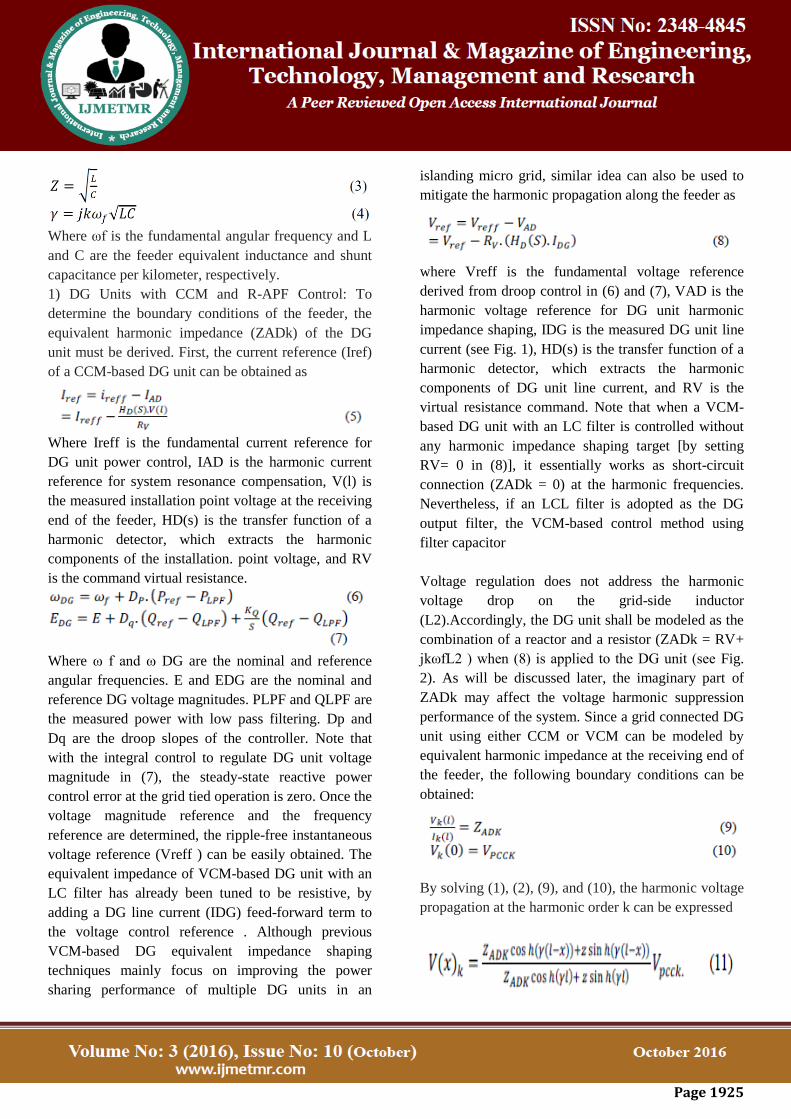
Page 1925
Where ωf is the fundamental angular frequency and L
and C are the feeder equivalent inductance and shunt
capacitance per kilometer, respectively.
1) DG Units with CCM and R-APF Control: To
determine the boundary conditions of the feeder, the
equivalent harmonic impedance (ZADk) of the DG
unit must be derived. First, the current reference (Iref)
of a CCM-based DG unit can be obtained as
Where Ireff is the fundamental current reference for
DG unit power control, IAD is the harmonic current
reference for system resonance compensation, V(l) is
the measured installation point voltage at the receiving
end of the feeder, HD(s) is the transfer function of a
harmonic detector, which extracts the harmonic
components of the installation. point voltage, and RV
is the command virtual resistance.
Where ω f and ω DG are the nominal and reference
angular frequencies. E and EDG are the nominal and
reference DG voltage magnitudes. PLPF and QLPF are
the measured power with low pass filtering. Dp and
Dq are the droop slopes of the controller. Note that
with the integral control to regulate DG unit voltage
magnitude in (7), the steady-state reactive power
control error at the grid tied operation is zero. Once the
voltage magnitude reference and the frequency
reference are determined, the ripple-free instantaneous
voltage reference (Vreff ) can be easily obtained. The
equivalent impedance of VCM-based DG unit with an
LC filter has already been tuned to be resistive, by
adding a DG line current (IDG) feed-forward term to
the voltage control reference . Although previous
VCM-based DG equivalent impedance shaping
techniques mainly focus on improving the power
sharing performance of multiple DG units in an
islanding micro grid, similar idea can also be used to
mitigate the harmonic propagation along the feeder as
where Vreff is the fundamental voltage reference
derived from droop control in (6) and (7), VAD is the
harmonic voltage reference for DG unit harmonic
impedance shaping, IDG is the measured DG unit line
current (see Fig. 1), HD(s) is the transfer function of a
harmonic detector, which extracts the harmonic
components of DG unit line current, and RV is the
virtual resistance command. Note that when a VCM-
based DG unit with an LC filter is controlled without
any harmonic impedance shaping target [by setting
RV= 0 in (8)], it essentially works as short-circuit
connection (ZADk = 0) at the harmonic frequencies.
Nevertheless, if an LCL filter is adopted as the DG
output filter, the VCM-based control method using
filter capacitor
Voltage regulation does not address the harmonic
voltage drop on the grid-side inductor
(L2).Accordingly, the DG unit shall be modeled as the
combination of a reactor and a resistor (ZADk = RV+
jkωfL2 ) when (8) is applied to the DG unit (see Fig.
2). As will be discussed later, the imaginary part of
ZADk may affect the voltage harmonic suppression
performance of the system. Since a grid connected DG
unit using either CCM or VCM can be modeled by
equivalent harmonic impedance at the receiving end of
the feeder, the following boundary conditions can be
obtained:
By solving (1), (2), (9), and (10), the harmonic voltage
propagation at the harmonic order k can be expressed

Page 1926
As With the obtained equation in (11), the impact of
DG active damping scheme to the harmonic voltage
propagation along the feeder can be easily analyzed.
Note that when the micro grid feeder is purely RL
impedance, the DG unit can still work as a virtual
harmonic resistor at the end of the feeder. In this case,
the DG unit has the capability of absorbing some PCC
nonlinear load current if it is designed and controlled
properly
B. DISTRIBUTED PARAMETER MODEL IN
ISLANDING OPERATION
The previous section focuses on the analysis of grid
tied DG units. For an islanding micro grid system, the
VCM operation of DG units is needed for direct
voltage support. To the best of the authors‟ knowledge,
the quantitative analysis of islanding micro grid
harmonic propagation is not available. When only a
single DG unit is placed in the islanding system,
constant voltage magnitude and constant frequency
(CVMCF) control can be used
Fig. 3. Equivalent circuit of a single islanding DG
unit at the kth harmonic frequency
On the other hand, for the operation of multiple DG
units in the micro grid (see Fig. 1), the droop control
method in (6) and (7) [by setting KQ = 0 in (7)] shall
be employed to realize proper power sharing among
these DG units. Considering the focus of this section is
to investigate the harmonic voltage damping in a
stand-alone islanding system, a single DG unit at the
receiving end of the feeder is considered. The circuit
model of an islanding system at the harmonic order k
is illustrated in Fig. 3, With the knowledge of
boundary conditions at both sending and receiving
ends as
the kth harmonic voltage distortion along the feeder
can be obtained
From (14), it can be noticed that the voltage
propagation in an islanding system harmonic is also
related to the DG-unitequivalent harmonic impedance.
In order to maintain satisfied voltage quality, the
equivalent harmonic impedance of islanding DG units
shall also be properly designed.
IV. REALIZATION OF VIRTUAL DAMPING
IMPEDANCE THROUGH DG VOLTAGE
CONTROL
It has been clarified that an LCL filter grid-side
inductor (L2) can affect the performance of
distribution system harmonic suppression, especially
in the case of multiple DG units. In order to
compensate the impact of LCL filter grid-side
inductor, the harmonic voltage damping scheme as
shown in (8) shall be further improved.
A. Conventional Voltage Tracking
First, a negative virtual inductor can be produced by
VCM. Accordingly, the modified voltage reference is
obtained as
Comparing (16) to (8), it can be noticed that an
additional voltage compensation term VComp is
deducted from the voltage control reference. The aim
of this voltage compensation term is to cancel the
harmonic voltage drop on the grid-side LCL filter
Page 1927
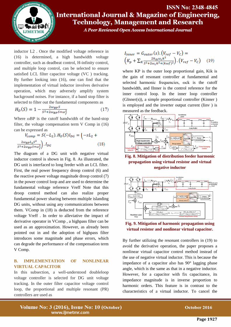
inductor L2 . Once the modified voltage reference in
(16) is determined, a high bandwidth voltage
controller, such as deadbeat control, H-infinity control,
and multiple loop control, can be selected to ensure
satisfied LCL filter capacitor voltage (VC ) tracking.
By further looking into (16), one can find that the
implementation of virtual inductor involves derivative
operation, which may adversely amplify system
background noises. For instance, if a band stop filter is
selected to filter out the fundamental components as
Where ωBP is the cutoff bandwidth of the band-stop
filter, the voltage compensation term V Comp in (16)
can be expressed as
The diagram of a DG unit with negative virtual
inductor control is shown in Fig. 8. As illustrated, the
DG unit is interfaced to long feeder with an LCL filter.
First, the real power frequency droop control (6) and
the reactive power voltage magnitude droop control (7)
in the power control loop and are used to determine the
fundamental voltage reference Vreff Note that this
droop control method can also realize proper
fundamental power sharing between multiple islanding
DG units, without using any communications between
them. VComp in (18) is deducted from the reference
voltage Vreff . In order to alleviative the impact of
derivative operator in VComp , a highpass filter can be
used as an approximation. However, as already been
pointed out in and the adoption of highpass filter
introduces some magnitude and phase errors, which
can degrade the performance of the compensation term
V Comp.
B. IMPLEMENTATION OF NONLINEAR
VIRTUAL CAPACITOR
In this subsection, a well-understood doubleloop
voltage controller is selected for DG unit voltage
tracking. In the outer filter capacitor voltage control
loop, the proportional and multiple resonant (PR)
controllers are used as
where KP is the outer loop proportional gain, Kik is
the gain of resonant controller at fundamental and
selected harmonic frequencies, ωck is the cutoff
bandwidth, and IInner is the control reference for the
inner control loop. In the inner loop controller
(GInner(s)), a simple proportional controller (Kinner )
is employed and the inverter output current (Iinv ) is
measured as the feedback.
Fig. 8. Mitigation of distribution feeder harmonic
propagation using virtual resistor and virtual
negative inductor
Fig. 9. Mitigation of harmonic propagation using
virtual resistor and nonlinear virtual capacitor.
By further utilizing the resonant controllers in (19) to
avoid the derivative operation, the paper proposes a
nonlinear virtual capacitor control method instead of
the use of negative virtual inductor. This is because the
impedance of a capacitor also has 90° lagging phase
angle, which is the same as that in a negative inductor.
However, for a capacitor with fix capacitance, its
impedance magnitude is in inverse proportion to
harmonic orders. This feature is in contrast to the
characteristics of a virtual inductor. To cancel the

Page 1928
impacts of LCL filter grid-side inductor without using
derivative operation, a nonlinear virtual capacitor with
the following frequency-dependent capacitance is
needed.
Where ωf is the fundamental angular frequency and
CV t is the command capacitance at the harmonic
order t. Note that an LCL filter inductance often has
some attenuation, if the line current is higher than the
current rating of the filter chokes. In this case, an
online estimation method can be used to identify the
real-time inductance of the LCL filter and the virtual
capacitance in (20) shall be modified accordingly.
With the control of nonlinear virtual capacitor as
shown in (20), the harmonic impact of the inductor L2
could be properly compensated. To realize this task,
the traditional harmonic detector in (17) can be
replaced by a family of selective harmonic separators
to extract DG line current harmonic contain (IDGt) at
each selected harmonic frequency. Afterwards, the
voltage dropson the nonlinear virtual capacitor can be
obtained as
Where HDt(s) is the harmonic detector to detect the tth
DG harmonic current IDGt. It can also be seen that
parallel resonant controllers used in the outer loop
voltage control in (19) are essentially a set of band-
pass filters with narrow bandwidth ωck and amplified
magnitudes Kik . Indeed, the harmonic selective
capability has already been embedded in the resonant
controllers. If arranged
Table ii
Dg unit parameters
Fig. 10. Harmonic voltage amplification during a
single DG unit grid connected operation (without
damping) [from upper to lower: (a) PCC voltage
(THD = 4.0%); (b) node 1 voltage (THD = 4.56%);
(c) node 3 voltage (THD = 10.91%); (d) node 5
voltage (THD = 12.59%); (e) DG unit filter
capacitor voltage (THD = 0.38%)].
Properly, resonant controllers can be further utilized to
realize the control of virtual nonlinear capacitor. First,
the instantaneous DG voltage reference Vreff derived
from (6) and (7) is always ripple-free and the
fundamental resonant controller can be adopted for
Vreff tracking. In addition, the regulation of virtual
resistor and virtual capacitor mainly focuses on the
performance at selected harmonic frequencies.
Therefore, parallel harmonic resonant controllers can
be utilized to control these virtual impedances. Once
the conventional PR controller is separated into two
parts, the modified outer loop control scheme is
illustrated as follows:
Page 1929
Note that the HD(s) is a harmonic detector, which has
0 db and 0° response at all selected harmonic
frequencies and HDt(s) is a selective harmonic
detector which only has 0 db and 0° response at the tth
harmonic frequency. By further utilizing the harmonic
selective feature of harmonic resonant controllers in
the PR controller, (23) can be further simplified as
With this modified outer loop controller, the DG unit
fundamental voltage tracking and harmonic virtual
impedance regulation can be realized separately. The
detailed DG controller with the control of virtual
nonlinear capacitor is shown in Fig. 9. In the revised
controller, the harmonic voltage references associated
with virtual resistor and virtual capacitor are only
regulated by the harmonic resonant controllers. It can
be seen that the derivative operator in Fig. 8 is avoided
in Fig. 9. It is true that the small proportional gain KP1
in (24) still induces some interference between
fundamental and harmonic components regulation.
However, the proportional gain in the PR controller is
normally very small compared to resonant gains. In
this paper, a small proportional gain (KP1 = 0.11) is
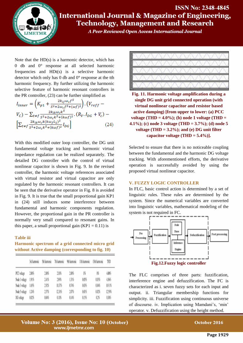
Table iii
Harmonic spectrum of a grid connected micro grid
without Active damping (corresponding to fig. 10)
Fig. 11. Harmonic voltage amplification during a
single DG unit grid connected operation (with
virtual nonlinear capacitor and resistor based
active damping) [from upper to lower: (a) PCC
voltage (THD = 4.0%); (b) node 1 voltage (THD =
4.1%); (c) node 3 voltage (THD = 3.7%); (d) node 5
voltage (THD = 3.2%); and (e) DG unit filter
capacitor voltage (THD = 5.4%)].
Selected to ensure that there is no noticeable coupling
between the fundamental and the harmonic DG voltage
tracking. With aforementioned efforts, the derivative
operation is successfully avoided by using the
proposed virtual nonlinear capacitor.
V. FUZZY LOGIC CONTROLLER
In FLC, basic control action is determined by a set of
linguistic rules. These rules are determined by the
system. Since the numerical variables are converted
into linguistic variables, mathematical modeling of the
system is not required in FC.
Fig.12.Fuzzy logic controller
The FLC comprises of three parts: fuzzification,
interference engine and defuzzification. The FC is
characterized as i. seven fuzzy sets for each input and
output. ii. Triangular membership functions for
simplicity. iii. Fuzzification using continuous universe
of discourse. iv. Implication using Mamdani‟s, „min‟
operator. v. Defuzzification using the height method.
Page 1930
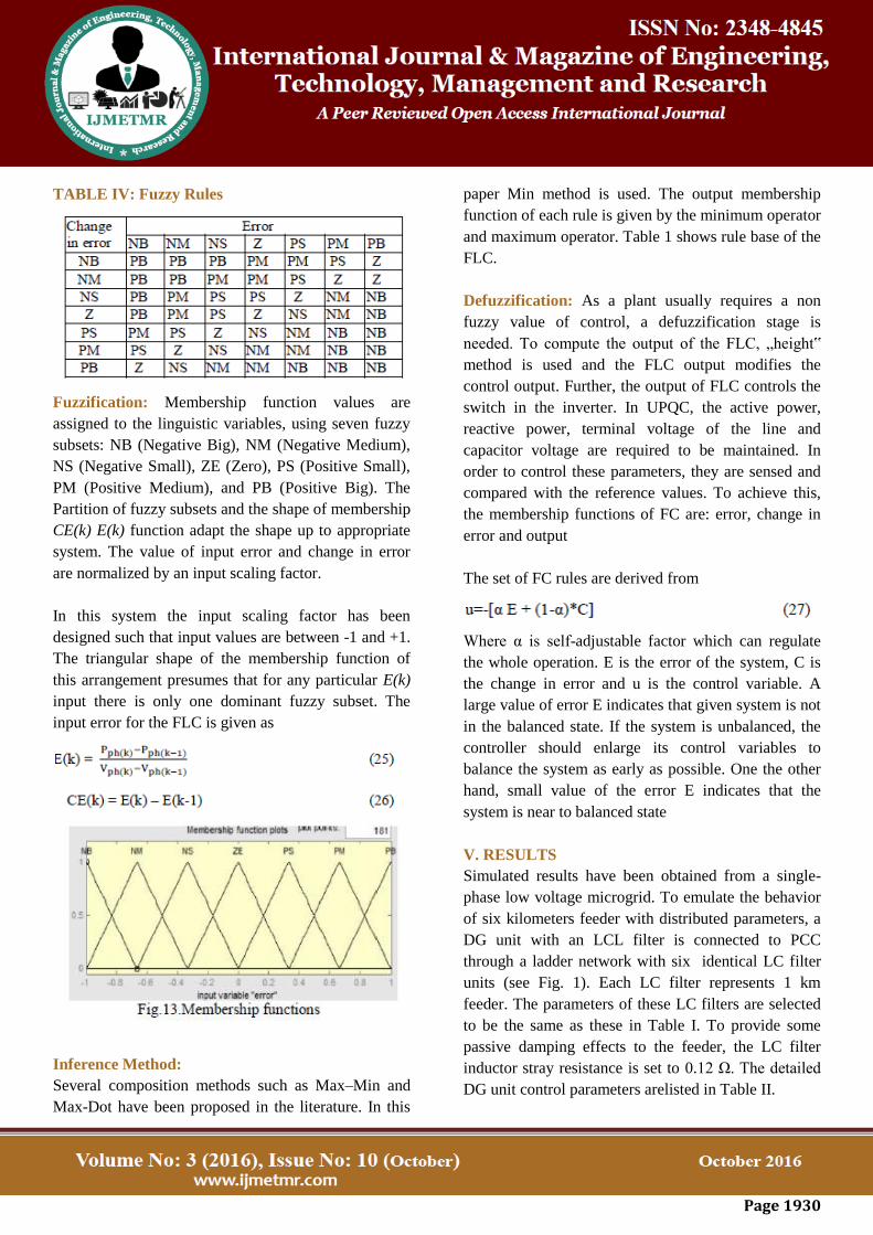
TABLE IV: Fuzzy Rules
Fuzzification: Membership function values are
assigned to the linguistic variables, using seven fuzzy
subsets: NB (Negative Big), NM (Negative Medium),
NS (Negative Small), ZE (Zero), PS (Positive Small),
PM (Positive Medium), and PB (Positive Big). The
Partition of fuzzy subsets and the shape of membership
CE(k) E(k) function adapt the shape up to appropriate
system. The value of input error and change in error
are normalized by an input scaling factor.
In this system the input scaling factor has been
designed such that input values are between -1 and +1.
The triangular shape of the membership function of
this arrangement presumes that for any particular E(k)
input there is only one dominant fuzzy subset. The
input error for the FLC is given as
Inference Method:
Several composition methods such as Max–Min and
Max-Dot have been proposed in the literature. In this
paper Min method is used. The output membership
function of each rule is given by the minimum operator
and maximum operator. Table 1 shows rule base of the
FLC.
Defuzzification: As a plant usually requires a non
fuzzy value of control, a defuzzification stage is
needed. To compute the output of the FLC, „height‟
method is used and the FLC output modifies the
control output. Further, the output of FLC controls the
switch in the inverter. In UPQC, the active power,
reactive power, terminal voltage of the line and
capacitor voltage are required to be maintained. In
order to control these parameters, they are sensed and
compared with the reference values. To achieve this,
the membership functions of FC are: error, change in
error and output
The set of FC rules are derived from
Where α is self-adjustable factor which can regulate
the whole operation. E is the error of the system, C is
the change in error and u is the control variable. A
large value of error E indicates that given system is not
in the balanced state. If the system is unbalanced, the
controller should enlarge its control variables to
balance the system as early as possible. One the other
hand, small value of the error E indicates that the
system is near to balanced state
V. RESULTS
Simulated results have been obtained from a single-
phase low voltage microgrid. To emulate the behavior
of six kilometers feeder with distributed parameters, a
DG unit with an LCL filter is connected to PCC
through a ladder network with six identical LC filter
units (see Fig. 1). Each LC filter represents 1 km
feeder. The parameters of these LC filters are selected
to be the same as these in Table I. To provide some
passive damping effects to the feeder, the LC filter
inductor stray resistance is set to 0.12 Ω. The detailed
DG unit control parameters arelisted in Table II.

Page 1931
A. SINGLE DG UNIT GRID-TIED OPERATION
At first, the performance of a grid-connected DG unit
with an LCL filter is examined. The PCC voltage in
this simulation is stiff and it has 2.0% distortion at
each lower order harmonic frequency (3rd, 5th, 7th,
and 9th harmonics).Fig.
Fig. 14. Harmonic voltage amplification during a
single DG unit islanding operation (without
damping) [from upper to lower: (a) PCC voltage
(THD = 15.2%); (b) node 1 voltage (THD = 14.7%);
(c) node 3 voltage (THD = 11.9%); (d) node 5
voltage (THD = 10.5%); and (e) DG unit filter
capacitor voltage (THD = 1.6%)].
Table v
Harmonic spectrum of an islanding micro grid
without active damping (corresponding to fig. 12)
Fig. 15. Harmonic voltage amplification during a
single DG unit islanding operation (with virtual
nonlinear capacitor and resistor based active
damping) [from upper to lower: (a) PCC voltage
(THD = 6.1%); (b) node 1 voltage (THD = 6.0%);
(c) node 3 voltage (THD = 5.2%); (d) node 5 voltage
(THD = 5.3%); and (e) DG unit filter capacitor
voltage (THD = 7.1%)].
B. SINGLE DG UNIT ISLANDING OPERATION
In addition to grid-connected operation, the
performance of a single DG unit in islanding operation
is also investigated. In this case, the PCC lad is a
single-phase diode rectifier and it is supplied by the
DG unit through long feeder. When the conventional
VCM without damping is adopted, the performance of
the system is obtained in Fig. 12. Similar to the grid-
tied operation, the voltage waveforms at PCC, nodes 1,
3, and 5, and DG unit filter capacitor are shown from
channels (a) to (e), respectively.
C. MULTIPLE DG UNITS GRID-TIED
OPERATION
To verify the circulating harmonic current between
multiple DG units, two grid-connected DG units at the
same power rating are placed at the receiving end of
the feeder.
Fig. 16. Harmonic voltage amplification along the
feeders (grid-tied operation of two parallel DG
units).

Page 1932
VI. CONCLUSION
In this paper, the impacts of voltage controlled and
current-controlled distributed generation (DG) units to
micro grid resonance propagation are compared. To
actively mitigate the resonance using DG units, an
enhanced DG unit component of the proposed
nonlinear virtual impedance is employed to
compensate the impact of dg unit LCL filter grid-side
inductor. The resistive element is responsible for
active damping. With properly controlled dg
equivalent harmonic impedance at chosen harmonic
frequencies, the proposed method can even eliminate
the harmonic circulating current among multiple dg
units with mismatched output filter parameters. Here
we are using the fuzzy controller compared to other
controllers due to its accurate performance
Comprehensive simulations are conducted to
substantiate the validity of the proposed method.
REFERENCES
[1] H. Akagi, “Active harmonic filters,” Proc. IEEE,
vol. 93, no. 12, pp. 2128–2141, Dec. 2005.
[2] H.Akagi, H. Fujita, and K. Wada, “A shunt active
filter based on voltage detection for harmonic
termination for radial power distribution system,”
IEEE Trans. Ind. Appl., vol. 35, no. 4, pp. 682–690,
Jul./Aug. 1995.
[3] K. Wada, H. Fujita, and H. Akagi, “Consideration
of a shunt active filter based on voltage detection for
installation on a long distribution feeder,” IEEE Trans.
Ind. Appl., vol. 38, no. 4, pp. 1123–1130, Jul./Aug.
2002.
[4] P.-T. Cheng and T.-L. Lee, “Distributed active
filter systems (DAFSs): A new approach to power
system harmonics,” IEEE Trans. Ind. Appl., vol. 42,
no. 5, pp. 1301–1309, Sep./Oct. 2006.
[5] T.-L. Lee and P.-T. Cheng, “Design of a new
cooperative harmonic filtering strategy for distributed
generation interface converters in an islanding
network,” IEEE Trans. Power Electron., vol. 42, no. 5,
pp. 1301–1309, Sep. 2007.
[6] T.-L. Lee, J.-C. Li, and P.-T. Cheng, “Discrete
frequency-tuning active filter for power system
harmonics,” IEEE Trans. Power Electron., vol. 24, no.
5, pp. 1209–1217, Apr. 2009.
[7] T.-L. Lee and S.-H. Hu, “Discrete frequencytuning
active filter to suppress harmonic resonances of
closed-loop distribution power system,” IEEE Trans.
Power Electron., vol. 26, no. 1, pp. 137–148, Dec.
2010.
[8] N. Pogaku and T. C. Green, “Harmonic mitigation
throughout a distribution system: A distributed-
generator-based solution,” IEE Proc. Gener. Transmits.
Disturb., vol. 153, no. 3, pp. 350– 358, May 2006.
[9] C. J. Gajanayake, D.M.Vilathgamuwa, P. C. Loh,
R. Teodorescu, and F. Blaabjerg, “Z-source inverter-
based flexible distributed generation system solution
for grid power quality improvement,” IEEE Trans.
Energy Convers., vol. 24, pp. 695–704, Sep. 2009.
[10] Y. W. Li, D. M.Vilathgamuwa, and P. C. Loch,
“Design, analysis and real-time testing of a controller
for multi bus micro grid system,” IEEE Trans. Power
Electron., vol. 19, no. 5, pp. 1195–1204, Sep. 2004.