Resolution A.1122(30) Adopted on 6 December 2017 (Agenda ...
72
I:\ASSEMBLY\30\RES\A 30-RES.1122.docx E ASSEMBLY 30th session Agenda item 11 A 30/Res.1122 18 December 2017 Original: ENGLISH Resolution A.1122(30) Adopted on 6 December 2017 (Agenda item 11) CODE FOR THE TRANSPORT AND HANDLING OF HAZARDOUS AND NOXIOUS LIQUID SUBSTANCES IN BULK ON OFFSHORE SUPPORT VESSELS (OSV CHEMICAL CODE) THE ASSEMBLY, RECALLING Article 15(j) of the Convention on the International Maritime Organization concerning the functions of the Assembly in relation to regulations and guidelines regarding maritime safety and the prevention and control of marine pollution from ships, RECALLING ALSO that regulation 11.2 of Annex II to the International Convention for the Prevention of Pollution from Ships, 1973, as modified by the Protocol of 1978 relating thereto, calls for guidelines to be developed by the Organization on the basis of which Administrations shall establish appropriate measures in respect of ships other than chemical tankers carrying noxious liquid substances in bulk identified in chapter 17 of the International Code for the Construction and Equipment of Ships Carrying Dangerous Chemicals in Bulk, in order to minimize the uncontrolled discharge into the sea of such substances, RECALLING FURTHER that it adopted, by resolution A.673(16), Guidelines for the transport and handling of limited amounts of hazardous and noxious liquid substances in bulk on offshore support vessels (LHNS Guidelines), RECOGNIZING the need to improve the provisions of the LHNS Guidelines in light of the evolution of the offshore industry and experience gained from implementing those Guidelines, HAVING CONSIDERED the recommendations of the Maritime Safety Committee, at its ninety-eighth session, and of the Marine Environment Protection Committee, at its seventy-first session, 1 ADOPTS the Code for the Transport and Handling of Hazardous and Noxious Liquid Substances in Bulk on Offshore Support Vessels (OSV Chemical Code), set out in the annex to the present resolution; 2 INVITES Governments to take action to implement the OSV Chemical Code from 1 July 2018; 3 AUTHORIZES the Maritime Safety Committee and the Marine Environment Protection Committee to keep the OSV Chemical Code under review and update it as may be necessary; 4 SUPERSEDES resolution A.673(16). ***
Transcript of Resolution A.1122(30) Adopted on 6 December 2017 (Agenda ...

I:\ASSEMBLY\30\RES\A 30-RES.1122.docx
E
ASSEMBLY 30th session Agenda item 11
A 30/Res.1122 18 December 2017 Original: ENGLISH
Resolution A.1122(30)
Adopted on 6 December 2017 (Agenda item 11)
CODE FOR THE TRANSPORT AND HANDLING OF HAZARDOUS AND NOXIOUS LIQUID SUBSTANCES IN BULK ON OFFSHORE SUPPORT VESSELS
(OSV CHEMICAL CODE)
THE ASSEMBLY,
RECALLING Article 15(j) of the Convention on the International Maritime Organization concerning the functions of the Assembly in relation to regulations and guidelines regarding maritime safety and the prevention and control of marine pollution from ships,
RECALLING ALSO that regulation 11.2 of Annex II to the International Convention for the Prevention of Pollution from Ships, 1973, as modified by the Protocol of 1978 relating thereto, calls for guidelines to be developed by the Organization on the basis of which Administrations shall establish appropriate measures in respect of ships other than chemical tankers carrying noxious liquid substances in bulk identified in chapter 17 of the International Code for the Construction and Equipment of Ships Carrying Dangerous Chemicals in Bulk, in order to minimize the uncontrolled discharge into the sea of such substances,
RECALLING FURTHER that it adopted, by resolution A.673(16), Guidelines for the transport and handling of limited amounts of hazardous and noxious liquid substances in bulk on offshore support vessels (LHNS Guidelines),
RECOGNIZING the need to improve the provisions of the LHNS Guidelines in light of the evolution of the offshore industry and experience gained from implementing those Guidelines,
HAVING CONSIDERED the recommendations of the Maritime Safety Committee, at its ninety-eighth session, and of the Marine Environment Protection Committee, at its seventy-first session,
1 ADOPTS the Code for the Transport and Handling of Hazardous and Noxious Liquid Substances in Bulk on Offshore Support Vessels (OSV Chemical Code), set out in the annex to the present resolution;
2 INVITES Governments to take action to implement the OSV Chemical Code from 1 July 2018;
3 AUTHORIZES the Maritime Safety Committee and the Marine Environment Protection Committee to keep the OSV Chemical Code under review and update it as may be necessary;
4 SUPERSEDES resolution A.673(16).
***


A 30/Res.1122 Annex, page 1
I:\ASSEMBLY\30\RES\A 30-RES.1122.docx
Annex
CODE FOR THE TRANSPORT AND HANDLING OF HAZARDOUS AND NOXIOUS
LIQUID SUBSTANCES IN BULK ON OFFSHORE SUPPORT VESSELS
(OSV CHEMICAL CODE)
TABLE OF CONTENTS
PREAMBLE .......................................................................................................................... 4
CHAPTER 1 – GENERAL ..................................................................................................... 4
1.1 Application ............................................................................................................... 4 1.2 Definitions ................................................................................................................ 6 1.3 Equivalents ............................................................................................................ 11 1.4 Surveys and certification ........................................................................................ 11
CHAPTER 2 – VESSEL SURVIVAL CAPABILITY AND LOCATION OF CARGO TANKS .................................................................................................................................12
2.1 General .................................................................................................................. 12 2.2 Freeboard and intact stability ................................................................................. 12 2.3 Non-cargo discharges below the freeboard deck ................................................... 13 2.4 Conditions of loading ............................................................................................. 13 2.5 Flooding assumptions ............................................................................................ 14 2.6 Damage assumptions ............................................................................................ 15 2.7 Standard of damage .............................................................................................. 17 2.8 Survival requirements ............................................................................................ 17 2.9 Location of cargo tanks .......................................................................................... 19
CHAPTER 3 – VESSEL DESIGN ........................................................................................19
3.1 Cargo segregation ................................................................................................. 19 3.2 Accommodation, service and machinery spaces and control stations .................... 21 3.3 Access to spaces in the cargo area ....................................................................... 21
CHAPTER 4 – SPECIAL REQUIREMENTS FOR PRODUCTS WITH A FLASHPOINT NOT EXCEEDING 60°C, TOXIC PRODUCTS AND ACID ...................................................22
4.1 General requirements for products with a flashpoint not exceeding 60°C, toxic products or acids ................................................................................................... 22
4.2 Products with a flashpoint not exceeding 60°C ...................................................... 23 4.3 Toxic products ....................................................................................................... 23 4.4 Acids...................................................................................................................... 24
CHAPTER 5 – CARGO CONTAINMENT .............................................................................24
5.1 Definitions .............................................................................................................. 24 5.2 Tank type requirements for individual products ...................................................... 25
CHAPTER 6 – CARGO TRANSFER ....................................................................................25
6.1 Piping scantlings .................................................................................................... 25 6.2 Piping fabrication and joining details ...................................................................... 27 6.3 Flange connections ................................................................................................ 28 6.4 Test requirements for piping .................................................................................. 28 6.5 Piping arrangements .............................................................................................. 28 6.6 Cargo-transfer control systems .............................................................................. 29 6.7 Vessels' cargo hoses ............................................................................................. 29

A 30/Res.1122 Annex, page 2
I:\ASSEMBLY\30\RES\A 30-RES.1122.docx
CHAPTER 7 – CARGO TANK VENTING ............................................................................30
7.1 General .................................................................................................................. 30 7.2 Types of tank venting systems ............................................................................... 31 7.3 Venting requirements for individual products ......................................................... 32 7.4 Cargo tank gas freeing .......................................................................................... 32
CHAPTER 8 – ELECTRICAL INSTALLATIONS .................................................................33
8.1 General requirements ............................................................................................ 33 8.2 Electrical requirements for individual products ....................................................... 34
CHAPTER 9 – FIRE-FIGHTING REQUIREMENTS .............................................................34
9.1 Application ............................................................................................................. 34 9.2 Cargo pump-rooms ................................................................................................ 35 9.3 Protection of the cargo area ................................................................................... 35 9.4 Special requirements ............................................................................................. 36
CHAPTER 10 – MECHANICAL VENTILATION IN THE CARGO AREA .............................36
10.1 Application ............................................................................................................. 36 10.2 Spaces normally entered during normal cargo handling operations ....................... 36 10.3 Spaces not normally entered ................................................................................. 38
CHAPTER 11 – INSTRUMENTATION AND AUTOMATION SYSTEMS..............................38
11.1 General .................................................................................................................. 38 11.2 Level indicators for cargo tanks ............................................................................. 38 11.3 Overflow control ..................................................................................................... 39 11.4 Vapour detection ................................................................................................... 39
CHAPTER 12 – POLLUTION PREVENTION REQUIREMENTS .........................................39
CHAPTER 13 – LIFE-SAVING APPLIANCES AND ARRANGEMENTS .............................40
CHAPTER 14 – PERSONNEL PROTECTION .....................................................................40
14.1 Protective equipment ............................................................................................. 40 14.2 First aid equipment ................................................................................................ 40 14.3 Safety equipment ................................................................................................... 40 14.4 Emergency equipment ........................................................................................... 41
CHAPTER 15 – OPERATIONAL REQUIREMENTS ............................................................42
15.1 General .................................................................................................................. 42 15.2 Cargo information .................................................................................................. 42 15.3 Personnel training .................................................................................................. 43 15.4 Opening of and entry into cargo tanks ................................................................... 43 15.5 Simultaneous carriage of deck cargo and products................................................ 43
CHAPTER 16 – BACKLOADING OF CONTAMINATED BULK LIQUIDS ...........................44
16.1 Preamble ............................................................................................................... 44 16.2 General .................................................................................................................. 45 16.3 Documentation ...................................................................................................... 45 16.4 Operation ............................................................................................................... 46
CHAPTER 17 – DISCHARGING AND LOADING OF PORTABLE TANKS ON BOARD ....47
17.1 Preamble ............................................................................................................... 48 17.2 General .................................................................................................................. 48 17.3 Arrangement of deck spread .................................................................................. 48 17.4 Shipment of cargo in portable tanks used as deck tanks ....................................... 49

A 30/Res.1122 Annex, page 3
I:\ASSEMBLY\30\RES\A 30-RES.1122.docx
CHAPTER 18 – CARRIAGE OF LIQUEFIED GASES .........................................................49
18.1 General requirements ............................................................................................ 49 18.2 Accommodation, service and machinery spaces and control stations .................... 50 18.3 Cargo containment ................................................................................................ 50 18.4 Materials of construction ........................................................................................ 50 18.5 Vent system for cargo containment ........................................................................ 50 18.6 Cargo transfer ........................................................................................................ 50 18.7 Vapour detection ................................................................................................... 51 18.8 Gauging and level detection .................................................................................. 51 18.9 Emergency shutdown system ................................................................................ 51 18.10 Personnel Protection ............................................................................................. 51 18.11 Carriage on open deck .......................................................................................... 51 18.12 Carriage of other liquefied gases listed in chapter 19 of the IGC Code .................. 51
APPENDIX 1 – MODEL FORM OF CERTIFICATE OF FITNESS ........................................53 APPENDIX 2 – GUIDELINES FOR TESTING PRIOR TO BACKLOADING ........................61 APPENDIX 3 – MODEL FORMAT FOR THE PROCEDURE FOR THE DISCHARGING AND LOADING OF PORTABLE TANKS CONTAINING DANGEROUS GOODS CARRIED AS DECK TANKS ON OFFSHORE SUPPORT VESSELS .................................66

A 30/Res.1122 Annex, page 4
I:\ASSEMBLY\30\RES\A 30-RES.1122.docx
PREAMBLE 1 The present Code has been developed for the design, construction and operation of offshore support vessels (OSVs) which transport hazardous and noxious liquid substances in bulk for the servicing and resupplying of offshore platforms, mobile offshore drilling units and other offshore installations, including those employed in the search for and recovery of hydrocarbons from the seabed. 2 The present Code has been developed in accordance with the requirements set forth in regulation 11.2 of Annex II to the International Convention for the Prevention of Pollution from Ships, 1973, as modified by the Protocol of 1978 relating thereto (MARPOL) and in recognition of the need for standards which provide an alternative to the International Code for the Construction and Equipment of Ships Carrying Dangerous Chemicals in Bulk (IBC Code) and the International Code for the Construction and Equipment of Ships Carrying Liquefied Gases in Bulk (IGC Code) for OSVs. 3 The basic philosophy of the present Code is to apply standards contained in the IBC Code and the IGC Code to the extent that is practicable and reasonable taking into account the unique design features and service characteristics of OSVs. 4 The Guidelines for the design and construction of offshore supply vessels, 2006 (resolution MSC.235(82)), as amended, are also applicable to OSVs subject to the present Code. 5 It is recognized that the technology of the offshore industry is complex and continuously evolving, as shown by the growing need for specialized vessels such as well-stimulation vessels. To meet the needs of the industry, the present Code should not remain static. Therefore, the Organization will periodically review the Code, taking into account both experience and technical development. Amendments to the Code involving provisions for new cargoes will be circulated periodically as new cargoes are proposed for carriage and the provisions are developed. CHAPTER 1 – GENERAL To provide an international standard for the safe carriage, by sea in bulk, of chemicals by setting the design and construction standards of vessels involved in such carriage and the equipment, so as to minimize the risks to the vessel, its crew and the environment, having regard to the nature of the products, including flammability, toxicity, asphyxiation, corrosivity and reactivity. 1.1 Application 1.1.1 The present Code applies to OSVs engaged in the carriage of the products identified in 1.1.9, regardless of size or voyage. 1.1.2 The present Code should also apply when the cargoes indicated in 1.1.9 are part of a blending or production process of cargoes used in the search for and exploitation of seabed mineral resources on board vessels used to facilitate such operations.

A 30/Res.1122 Annex, page 5
I:\ASSEMBLY\30\RES\A 30-RES.1122.docx
1.1.3 Unless expressly provided otherwise, the present Code applies to OSVs the keels of which are laid or which, on or after 1 July 2018, are at the stage where:
.1 construction identifiable with the vessel begins; and .2 assembly has commenced comprising at least 50 tonnes or 1% of the
estimated mass of all structural material, whichever is less; 1.1.4 Existing OSVs the keel of which were laid or which were at a similar stage of construction on or after 19 April 1990 and before the date specified in 1.1.3 may be permitted to carry products as assigned for carriage on a type 2 ship in the IBC Code, provided that those OSVs comply with the present Code, except for the stability provisions in chapter 2 of the present Code, and subject to the satisfaction of the Administration. 1.1.5 A vessel, irrespective of the date of construction, which is converted for the carriage of bulk liquids subject to the present Code on or after the date specified in 1.1.3 should be treated as a vessel constructed on the date on which such conversion commences. An OSV which transports a cargo subject to the present Code and undergoes modification for the transport of additional cargoes falling under the present Code should not be considered as a vessel which has undergone a conversion. 1.1.6 The present Code applies only in the case of bulk carriage involving transfer of the cargo to or from its containment which forms part of the vessel or remains on board. 1.1.7 For requirements regulating the transport of dangerous goods and marine pollutants in packaged form, including transport of dangerous goods in portable tanks, refer to the International Maritime Dangerous Goods Code (IMDG Code). 1.1.8 The present Code applies in addition to the Guidelines for the design and construction of offshore supply vessels (resolution MSC.235(82)), as amended. Where the present Code sets forth alternative safety standards, the standards in the present Code should be applied. 1.1.9 Products which may be carried subject to the present Code are:
.1 products which are listed in chapters 17 or 18 of the IBC Code and the latest
edition of the MEPC.2/Circular (Provisional categorization of liquid substances in accordance with MARPOL Annex II and the IBC Code) and their related references to chapters 15 and 19; or
.2 oil-based/water-based mud containing mixtures of products listed in
chapters 17 and 18 of the IBC Code and the MEPC.2 Circular; or .3 liquid carbon dioxide (high purity and reclaimed quality) and liquid nitrogen; or .4 contaminated backloads.
1.1.10 For a product proposed for carriage in bulk, but not listed in chapters 17 or 18 of the IBC Code, the Administration and port Administrations involved in such carriage should prescribe the suitable preliminary conditions for the carriage, having regard to the criteria for hazard evaluation of bulk chemicals. For the evaluation of the pollution hazard of such a product and assignment of its pollution category, the procedure specified in regulation 6.3 of MARPOL Annex II should be followed. IMO should be notified of the preliminary conditions for consideration for inclusion of the product in the IBC Code.

A 30/Res.1122 Annex, page 6
I:\ASSEMBLY\30\RES\A 30-RES.1122.docx
1.2 Definitions
The following definitions apply unless expressly provided otherwise (additional definitions are given in individual chapters).
1.2.1 Accommodation spaces are those spaces used for public spaces, corridors, lavatories, cabins, offices, hospitals, cinemas, games and hobbies rooms, barber shops, pantries containing no cooking appliances and similar spaces.
1.2.2 Administration means the Government of the State whose flag the vessel is entitled to fly.
1.2.3 Anniversary date means the day and the month of each year that will correspond to the date of expiry of the Certificate of Fitness.
1.2.4 Backload means contaminated bulk liquids, taken on board a vessel offshore, for transport either back to shore or to an alternate offshore site.
1.2.5 Blending additives means small amounts of liquid substances used during blending of products or production processes of cargoes for use in the search for and exploitation of seabed mineral resources on board vessels used to facilitate such operations.
1.2.6 Breadth (B) means the maximum breadth of the vessel, measured amid vessels to the moulded line of the frame in a vessel with a metal shell and to the outer surface of the hull in a vessel with a shell of any other material. The breadth (B) should be measured in metres.
1.2.7 Cargo area is that part of the OSV where:
.1 a pollution hazard only substance having a flashpoint exceeding 60°C and not defined as toxic is likely to be present and includes cargo tanks, portable tanks used as deck cargo tanks, slop tanks, cargo pump-rooms, pump-rooms adjacent to cargo tanks and enclosed spaces in which pipes containing cargoes are located; areas on open deck are not considered part of the cargo area;
.2 a safety hazard substance having a flashpoint exceeding 60°C and not
defined as a toxic is likely to be present and includes cargo tanks, portable tanks used as deck cargo tanks, slop tanks, cargo pump-rooms, pump-rooms adjacent to cargo tanks, hold spaces in which independent tanks are located, cofferdams surrounding integral tanks, enclosed spaces in which pipes containing cargoes are located and the following deck areas:
.1 within 3 m of cargo tank installed on deck or portable tanks used as
deck cargo tanks; .2 areas on open deck, or semi-enclosed spaces on deck, within 3 m
of any cargo tank access outlet; .3 areas on open deck over an integral tank without an overlaying
cofferdam plus the open deck area extending transversely and longitudinally for a distance of 3 m beyond each side of the tank;

A 30/Res.1122 Annex, page 7
I:\ASSEMBLY\30\RES\A 30-RES.1122.docx
.4 areas on open deck, or semi-enclosed spaces on deck, within 3 m of cargo manifold valve, cargo valve, cargo pipe flange, except spaces within the 3 m zone that are separated by an enclosed bulkhead to the minimum height as given in 1.2.7.2.6;
.5 areas on open deck, or semi-enclosed spaces on open deck above
and in the vicinity of any cargo tank vent outlet intended for the passage of large volumes of vapour mixture during cargo loading, within a vertical cylinder of unlimited height and 3 m radius centred upon the centre of the outlet, and within a hemisphere of 3 m radius below the outlet;
.6 areas on the open deck within spillage coamings surrounding cargo
manifold valves and 3 m beyond these, up to a height of 2.4 m above the deck; and
.7 compartments for cargo hoses;
.3 a substance having a flashpoint not exceeding 60°C, or defined as toxic or
vapours of such cargo, is likely to be present and includes cargo tanks, portable tanks used as deck cargo tanks, slop tanks, cargo pump-rooms, pump-rooms adjacent to cargo tanks, hold spaces in which independent tanks are located, cofferdams surrounding integral tanks, enclosed spaces in which pipes containing cargoes are located and the following deck areas: .1 within 3 m of cargo tank installed on deck or portable tanks used as
deck cargo tanks; .2 areas on open deck, or semi-enclosed spaces on deck, within 4.5 m
of gas or vapour outlet, cargo manifold valve, cargo valve, cargo pipe flange, cargo pump-room ventilation outlets and cargo tank openings for pressure release provided to permit the flow of small volumes of gas or vapour mixtures caused by thermal variation;
.3 areas on open deck, or semi-enclosed spaces on open deck above
and in the vicinity of any cargo gas outlet intended for the passage of large volumes of gas or vapour mixture during cargo loading, within a vertical cylinder of unlimited height and 10 m radius centred upon the centre of the outlet, and within a hemisphere of 10 m radius below the outlet;
.4 areas on open deck, or semi-enclosed spaces on deck, within 3 m
of cargo pump-room entrances, cargo pump-room ventilation inlet, openings into cofferdams;
.5 areas on the open deck within spillage coamings surrounding cargo
manifold valves and 3 m beyond these, up to a height of 2.4 m above the deck;
.6 compartments for cargo hoses; and .7 within the hose landing area.
A 30/Res.1122 Annex, page 8
I:\ASSEMBLY\30\RES\A 30-RES.1122.docx
1.2.8 Cargo control station means a location that is manned during cargo transfer operations for the purpose of directing or controlling the loading or unloading of cargo. 1.2.9 Cargo pump-room is a space containing pumps and their accessories for the handling of the products covered by the present Code. 1.2.10 Cofferdam is the isolating space between two adjacent steel bulkheads or decks. This space may be a void space or a ballast space. 1.2.11 Control stations are those spaces in which vessels' radio or main navigating equipment or the emergency source of power is located or where the fire-recording or fire-control equipment is centralized. This does not include special fire-control equipment which can be most practically located in the cargo area. 1.2.12 Conversion means a vessel in an unrelated service modified for use as an OSV. Special purpose ships (operated under the Code of Safety for Special Purpose Ships, 2008 (2008 SPS Code)) in support-related service configurations are not considered "in an unrelated service". 1.2.13 Dangerous chemicals means any liquid chemicals designated as presenting a safety hazard, based on the safety criteria for assigning products to chapter 17 of the IBC Code. 1.2.14 Dangerous goods mean the substances, materials and articles covered by the IMDG Code. 1.2.15 Deadweight means the difference in metric tons between the displacement of an OSV in water of a density of 1.025 at the load waterline corresponding to the assigned summer freeboard and the lightweight of the vessel. 1.2.16 Deck spread means portable tanks, piping, equipment, processing equipment and control stations secured to the vessel by permanent means and used in the operation of the vessel. 1.2.17 Density is the ratio of the mass to the volume of a product, expressed in terms of kilograms per cubic metre. This applies to liquids, gases and vapours. 1.2.18 Flashpoint is the temperature in degrees Celsius at which a product will give off enough flammable vapour to be ignited. Values given in the present Code are those for a "closed cup test" determined by an approved flashpoint apparatus. 1.2.19 Hazardous substance is any substance either listed in chapter 17 of the IBC Code or having a hazard more severe than one of the minimum hazard criteria given in criteria for hazard evaluation of bulk chemicals as approved by the Organization. 1.2.20 Hold space is the space enclosed by the vessel's structure in which an independent cargo tank is situated. 1.2.21 Hose landing area means an area on the main deck, except those in compartments for cargo hoses, where cargo hoses of substances having a flashpoint not exceeding 60°C and/or defined as toxic are located during cargo transfer. 1.2.22 Independent means that a piping or venting system, for example, is in no way connected to another system and that there are no provisions available for the potential connection to other systems.

A 30/Res.1122 Annex, page 9
I:\ASSEMBLY\30\RES\A 30-RES.1122.docx
1.2.23 IBC Code means the International Code for the Construction and Equipment of Ships Carrying Dangerous Chemicals in Bulk (resolutions MSC.4(48) and MEPC.19(22)), as amended. 1.2.24 IGC Code means the International Code for the Construction and Equipment of Ships Carrying Liquefied Gases in Bulk (resolution MSC.5(48)), as amended. 1.2.25 IMDG Code means the International Maritime Dangerous Goods Code (resolution MSC.406(96)), as amended. 1.2.26 Length (L) means 96% of the total length on a waterline at 85% of the least moulded depth measured from the top of the keel, or the length from the foreside of the stem to the axis of the rudder stock on that waterline, if that is greater. In vessels designed with a rake of keel, the waterline on which this length is measured should be parallel to the designed waterline. The length (L) should be measured in metres. 1.2.27 Lightweight means the displacement of an OSV in metric tons without cargo, fuel, lubricating oil, ballast water, fresh water and feed water in tanks, consumable stores, and crew and their effects. 1.2.28 Machinery spaces of category A are those spaces and trunks to such spaces which either contain:
.1 internal combustion machinery used for main propulsion; .2 internal combustion machinery used for purposes other than main propulsion
where such machinery has in the aggregate a total power output of not less than 375 kW; or
.3 any oil-fired boiler or oil fuel unit or any oil-fired equipment other than boilers,
such as inert gas generators, incinerators, etc. 1.2.29 Machinery spaces are machinery spaces of category A and other spaces containing propulsion machinery, boilers, oil fuel units, steam and internal combustion engines, generators and major electrical machinery, oil filling station, refrigerating, stabilizing, ventilation and air conditioning machinery, and similar spaces, and trunks to such spaces. 1.2.30 MARPOL means the International Convention for the Prevention of Pollution from Ships, 1973, as modified by the Protocol of 1978 relating thereto, as amended. 1.2.31 Noxious liquid substance means any substance indicated in the Pollution Category column of chapter 17 or 18 of the IBC Code, or the current MEPC.2 Circular or provisionally assessed under the requirements of regulation 6.3 of MARPOL Annex II as falling into categories X, Y or Z. 1.2.32 Offshore portable tank means a portable tank specially designed for repeated use for transport of dangerous goods to, from and between offshore facilities. An offshore portable tank is designed and constructed in accordance with the Guidelines for the approval of offshore containers handled in open seas (MSC/Circ.860).

A 30/Res.1122 Annex, page 10
I:\ASSEMBLY\30\RES\A 30-RES.1122.docx
1.2.33 Offshore support vessels (OSVs) are:
.1 multi-mission vessels which are primarily engaged in the transport of stores, materials and equipment to and from mobile offshore drilling units, fixed and floating platforms and other similar offshore installations; or
.2 multi-mission vessels, including well-stimulation vessels, but excluding
mobile offshore drilling units, derrick barges, pipe-laying barges and floating accommodation units, which are otherwise primarily engaged in supporting the work of offshore installations.
1.2.34 Oil fuel unit is the equipment used for the preparation of oil fuel for delivery to an oil- fired boiler, or equipment used for the preparation for delivery of heated oil to an internal combustion engine, and includes any oil pressure pumps, filters and heaters dealing with oil at a gauge pressure of more than 0.18 MPa. 1.2.35 Open deck is defined as an open or semi-enclosed space on cargo deck or inside of the cargo rail. Semi-enclosed spaces are those spaces that either:
.1 are open at two ends; or .2 have an opening at one end and are provided with adequate natural
ventilation effective over their entire length through permanent openings distributed in the side plating or deckhead or from above, the openings having a total area of at least 10% of the total area of the space sides.
1.2.36 Organization is the International Maritime Organization (IMO). 1.2.37 Permeability of a space means the ratio of the volume within that space which is assumed to be occupied by water to the total volume of that space. 1.2.38 Pollution hazard only substance means a substance having an entry only of "P" in column d in chapter 17 of the IBC Code. 1.2.39 Port Administration means the appropriate authority of the country for the port where the vessel is loading or unloading. 1.2.40 Portable tank means a multimodal tank used for the transport of dangerous goods. 1.2.41 Propulsion shaft tunnel is the tunnel or space in which the mechanical transfer of power to a propulsion unit is run. 1.2.42 Public spaces are those portions of the accommodation spaces which are used for halls, dining rooms, lounges and similar permanently enclosed spaces. 1.2.43 Pump-room is a space, located in the cargo area, containing pumps and their accessories for the handling of ballast and oil fuel. 1.2.44 Recognized standards are applicable international or national standards acceptable to the Administration or standards laid down and maintained by an organization which comply with the standards adopted by IMO and which are recognized by the Administration. 1.2.45 Safety hazard substance means a substance having an entry of "S" or "S/P" in column d in chapter 17 of the IBC Code.
A 30/Res.1122 Annex, page 11
I:\ASSEMBLY\30\RES\A 30-RES.1122.docx
1.2.46 Separate means that a cargo piping system or cargo vent system, for example, is not connected to another cargo piping or cargo vent system. 1.2.47 Service spaces are those spaces used for galleys, pantries containing cooking appliances, lockers, mail and specie rooms, storerooms, workshops other than those forming part of the machinery spaces and similar spaces and trunks to such spaces. 1.2.48 SOLAS means the International Convention for the Safety of Life at Sea, 1974, as amended. 1.2.49 Underdeck access way is a passage passing through the underdeck cargo area without being part of the cargo area providing access to essential areas for operation of the vessel, such as thruster room, propulsion room or steering gear room. The access way may be used to route non-cargo piping and cabling. 1.2.50 Vapour pressure is the equilibrium pressure of the saturated vapour above a liquid expressed in pascals (Pa) at a specified temperature. 1.2.51 Void space is an enclosed space in the cargo area external to a cargo tank, other than a hold space, ballast space, oil fuel tank, cargo pump-room, pump-room, or any space in normal use by personnel. 1.2.52 Well-stimulation vessel means an OSV with specialized equipment and industrial personnel that delivers products and services directly into a well-head.
1.3 Equivalents
1.3.1 Where the present Code requires that a particular fitting, material, appliance, apparatus, item of equipment or type thereof should be fitted or carried on an OSV, or that any particular provision should be made, or any procedure or arrangement should be complied with, the Administration may allow any other fitting, material, appliance, apparatus, item of equipment or type thereof to be fitted or carried, or any other provision, procedure or arrangement to be made in that vessel, if it is satisfied by trial thereof or otherwise that such fitting, material, appliance, apparatus, item of equipment or type thereof or that any particular provision, procedure or arrangement is at least as effective as that required by the Code. However, the Administration may not allow operational methods or procedures to be made an alternative to a particular fitting, material, appliance, apparatus, item of equipment, or type thereof, which are prescribed by the Code, unless such substitution is specifically allowed by the Code. 1.3.2 Where the Administration allows any fitting, material, appliance, apparatus, item of equipment, or type thereof, or provision, procedure, or arrangement, or novel design or application to be substituted, it should communicate to the Organization the particulars thereof together with a report on the evidence submitted so that the Organization may circulate the same to other Parties to SOLAS or MARPOL, for the information of their officers.
1.4 Surveys and certification
1.4.1 Following a satisfactory initial survey of an OSV, the Administration or its duly authorized organization should issue a certificate, the model form of which is set out in appendix 1, suitably endorsed to certify compliance with the provisions of the present Code. If the language used is not English, French or Spanish, the text should include the translation into one of those languages. The certificate should indicate the cargoes regulated by the present Code that the vessel is permitted to carry with any relevant carriage conditions and should have a period of validity not exceeding five years.

A 30/Res.1122 Annex, page 12
I:\ASSEMBLY\30\RES\A 30-RES.1122.docx
1.4.2 The certificate issued under the present Code should have the same force and receive the same recognition as the certificate issued under regulation 7 of MARPOL Annex II and regulations VII/10 and VII/13 of SOLAS. 1.4.3 The validity of the certificate referred to in 1.4.1 should be subject to the renewal, intermediate, annual and additional surveys required by the IBC Code, the IGC Code and MARPOL Annex II. CHAPTER 2 – VESSEL SURVIVAL CAPABILITY AND LOCATION OF CARGO TANKS To ensure that the cargo tanks are located in protected location(s) for the event of minor hull damage and that the vessel can survive the assumed flooding conditions. 2.1 General 2.1.1 OSVs subject to the present Code should survive the normal effects of flooding following assumed hull damage caused by some external force. In addition, to safeguard the vessel and the environment, the cargo tanks should be protected from penetration in the case of minor damage to the vessel resulting, for example, from contact with a jetty or an offshore installation, and given a measure of protection from damage in the case of collision or stranding, by locating them at specified minimum distances inboard from the vessel's shell plating. Both the assumed damage and the proximity of the cargo tanks to the vessel's shell should be dependent upon the degree of hazard presented by the products to be carried. 2.1.2 The design standards of this chapter should be applied according to the ship type required for cargoes containing mixtures and individual products indicated in chapter 17 of the IBC Code and the latest edition of the MEPC.2 Circular. 2.1.3 OSVs subject to the present Code may be designed without cargo tank capacity limitation; however, the requirements of this chapter will be applied according to the ship type classified in the IBC Code and quantity of products carried on any single voyage. 2.1.4 If a vessel is intended to carry more than one product listed in chapter 17 of the IBC Code and the latest edition of the MEPC.2 Circular, the standard of damage should correspond to that product having the most stringent ship type provision. The provisions for the location of individual cargo tanks, however, need only be applied based upon the vessel types related to the respective products certified to be carried. 2.1.5 The provisions for cargo ships in SOLAS chapter II-1, parts B, B-1, B-2 and B-4, should apply to vessels covered by the present Code, except that SOLAS regulations II-1/6 to II-1/7-3 need not apply, unless expressly provided otherwise. 2.2 Freeboard and intact stability 2.2.1 OSVs subject to the present Code may be assigned the minimum freeboard permitted by the International Convention on Load Lines in force. 2.2.2 The intact stability of the vessel in all seagoing conditions should comply with the International Code on Intact Stability, 2008 (resolution MSC.267(85)), as amended. 2.2.3 Solid ballast should not normally be used in double-bottom spaces in the cargo area. Where, however, because of stability considerations, the fitting of solid ballast in such spaces becomes unavoidable, then its disposition should be governed by the need to ensure that the impact loads resulting from bottom damage are not directly transmitted to the cargo tank structure.

A 30/Res.1122 Annex, page 13
I:\ASSEMBLY\30\RES\A 30-RES.1122.docx
2.2.4 The master of the vessel should be supplied with a loading and stability information booklet. This booklet should contain details of typical service and ballast conditions, provisions for evaluating other conditions of loading and a summary of the vessel's survival capabilities. In addition, the booklet should contain sufficient information to enable the master to load and operate the vessel in a safe and seaworthy manner. All OSVs of 500 gross tonnage and above should comply with SOLAS regulation II-1/5-1. 2.2.5 OSVs subject to 2.6.1 and those vessels with a length of 80 m or more subject to 2.6.2 should be fitted with a stability instrument1 capable of verifying compliance with intact and damage stability provisions, approved by the Administration, having regard to the performance standards recommended by the Organization.2 2.3 Non-cargo discharges below the freeboard deck 2.3.1 The provision and control of valves fitted to non-cargo discharges led through the shell from spaces below the freeboard deck or from within superstructures and deckhouses on the freeboard deck fitted with weathertight doors should comply with the requirements of the relevant regulation of the International Convention on Load Lines in force, except that the choice of valves should be limited to:
.1 one automatic non-return valve with a positive means of closing from above the freeboard deck; or
.2 where the vertical distance from the summer load waterline to the inboard
end of the discharge pipe exceeds 0.01L, two automatic non-return valves without positive means of closing, provided that the inboard valve is always accessible for examination under service conditions.
2.3.2 For the purpose of this chapter, "summer load line" and "freeboard deck" have the meanings as defined in the International Convention on Load Lines in force. 2.3.3 The automatic non-return valves referred to in 2.3.1.1 and 2.3.1.2 should be fully effective in preventing admission of water into the vessel, taking into account the sinkage, trim and heel in survival provisions in 2.8, and should comply with recognized standards. 2.4 Conditions of loading Damage survival capability should be investigated on the basis of loading information submitted to the Administration for all anticipated conditions of loading and variations in draught and trim for the conditions for cargoes which the vessels is certified to carry. Conditions where the OSV is not carrying products covered by the present Code, or is carrying only residues of such products, need not be considered for the purpose of the present Code.
1 Refer to the IBC Code, paragraphs 2.2.6 and 2.2.7. 2 Refer to part B of chapter 4 of the International Code on Intact Stability, 2008 (resolution MSC.267(85)),
as amended; section 4 of the Guidelines for the approval of stability instruments (MSC.1/Circ.1229)), as amended; and the technical standards defined in part 1 of the Guidelines for verification of damage stability requirements for tankers (MSC.1/Circ.1461).

A 30/Res.1122 Annex, page 14
I:\ASSEMBLY\30\RES\A 30-RES.1122.docx
2.5 Flooding assumptions 2.5.1 The provisions of 2.8 should be confirmed by calculations which take into consideration the design characteristics of the vessel; the arrangements, configuration and contents of the damaged compartments; the distribution, relative densities and the free surface effects of liquids; and the draught and trim for all conditions of loading. 2.5.2 The permeability of spaces assumed to be damaged should be as follows:
Spaces Permeability
Appropriated to stores 0.60
Occupied by accommodation 0.95
Occupied by machinery 0.85
Voids 0.95
Intended for consumable liquids 0 to 0.95*
Intended for other liquids 0 to 0.95*
Intended for dry cargo 0.95
* The permeability of partially filled tanks should be consistent with the amount of liquid carried in the tank.
2.5.3 Wherever damage penetrates a tank containing liquids it should be assumed that the contents are completely lost from that compartment and replaced by salt water up to the level of the final plane of equilibrium. 2.5.4 Every watertight division within the maximum extent of damage defined in 2.6.1 and 2.6.2 and considered to have sustained damage in positions given in 2.7 should be assumed to be penetrated. Where damage less than the maximum is being considered in accordance with 2.6.3, only watertight divisions or combinations of watertight divisions within the envelope of such lesser damage should be assumed to be penetrated:
.1 where a transverse watertight bulkhead is located within the transverse extent of assumed damage and is stepped in way of a double bottom or side tank by more than 3.05 m, the double bottom or side tanks adjacent to the stepped portion of the transverse watertight bulkhead should be considered as flooded simultaneously; and
.2 if the distance between the transverse planes passing through the nearest
stepped portions of the bulkheads is less than the longitudinal extent of damage given in 2.6.1 and 2.6.2, only one of these bulkheads should be regarded as effective.
2.5.5 The vessel should be so designed as to keep unsymmetrical flooding to the minimum consistent with efficient arrangements. 2.5.6 Equalization arrangements requiring mechanical aids such as valves or cross-levelling pipes, if fitted, should not be considered for the purpose of reducing an angle of heel or attaining the minimum range of residual stability to meet the provisions of 2.8 and

A 30/Res.1122 Annex, page 15
I:\ASSEMBLY\30\RES\A 30-RES.1122.docx
sufficient residual stability should be maintained during all stages where equalization is used. Spaces which are linked by ducts of large cross-sectional area may be considered to be common. 2.5.7 If pipes, ducts, trunks or tunnels are situated within the assumed extent of damage penetration, as defined in 2.6, arrangements should be such that progressive flooding cannot thereby extend to compartments other than those assumed to be flooded for each case of damage. 2.5.8 For vessels subject to 2.6.1 the buoyancy of any superstructure directly above the side damage should be disregarded. The unflooded parts of superstructures beyond the extent of damage, however, may be taken into consideration provided that:
.1 they are separated from the damaged space by watertight divisions and the provisions of 2.8.2.2 in respect of these intact spaces are complied with; and
.2 openings in such divisions are capable of being closed by remotely operated
sliding watertight doors and unprotected openings are not immersed within the minimum range of residual stability required in 2.8; however, the immersion of any other openings capable of being closed weathertight may be permitted.
2.6 Damage assumptions 2.6.1 For vessels carrying more than 1200 m3 of products classified in the IBC Code as requiring type 3 ship or type 2 ship, or more than 150 m3 of products classified in the IBC Code as requiring type 1 ship, the assumed maximum extent of damage should be:
.1 Side damage
Longitudinal extent
Transverse extent Vertical extent
1/3L2/3
B/5 (measured inboard from the vessel's side at right angles to the centreline at the level of the summer load line)
Upwards without limit (measured from the moulded line of the bottom shell plating at centreline)

A 30/Res.1122 Annex, page 16
I:\ASSEMBLY\30\RES\A 30-RES.1122.docx
.2 Bottom damage
Location of damage
Longitudinal extent
Transverse extent Vertical extent
.1
Within 0.3L (measured from the forward perpendicular)
1/3L2/3 B/6
B/15 or 6 m, whichever is less (measured from the moulded line of the bottom shell plating at centreline (see 2.9.2))
.2 Any other part of the vessel
1/3L2/3 or 5 m, whichever is less
B/6 or 5 m, whichever is less
B/15 or 6 m, whichever is less (measured from the moulded line of the bottom shell plating at centreline (see 2.9.2)
2.6.2 For vessels carrying not more than 1200 m3 of products classified in the IBC Code as requiring type 3 ship or type 2 ship, and not more than 150 m3 of products classified in the IBC Code as requiring type 1 ship the assumed maximum extent of damage should be:
Side damage
Vessel length Longitudinal extent
Transverse extent Vertical extent
.1 24≤L≤43 m 0.1L
760 mm (measured inboard from the vessel's side at right angles to the centreline at the level of the summer load line)
From the underside of the cargo deck, or continuation thereof, downward for the full depth of the vessel
.2 43<L<80 m 3 m + 0.03L
760 mm (measured inboard from the vessel's side at right angles to the centreline at the level of the summer load line)
From the underside of the cargo deck, or continuation thereof, downward for the full depth of the vessel
.3 80≤L≤100 m 1/3L2/3
B/20, but not less than 760 mm (measured inboard from the vessel's side at right angles to the centreline at the level of the summer load line)
From the underside of the cargo deck, or continuation thereof, downward for the full depth of the vessel
.4 L>100 m 1/3L2/3
B/15, but not less than 760 mm (measured inboard from the vessel's side at right angles to the centreline at the level of the summer load line)
From the underside of the cargo deck, or continuation thereof, downward for the full depth of the vessel
2.6.3 If any damage of a lesser extent than the maximum damage specified in 2.6.1 or 2.6.2 would result in a more severe condition, such damage should be considered.

A 30/Res.1122 Annex, page 17
I:\ASSEMBLY\30\RES\A 30-RES.1122.docx
2.6.4 A transverse watertight bulkhead extending from the vessel's side to a distance inboard not less than the transverse extent of damage indicated in 2.6.2 measured at the level of the summer load line joining longitudinal watertight bulkheads may be considered as a transverse watertight bulkhead for the purpose of the damage calculations in 2.6.2. 2.7 Standard of damage Vessels should be capable of surviving damage with the assumptions in 2.5 and 2.6 determined by the following standards:
.1 a vessel that carries more than 150 m3 of ship type 1 products should be assumed to sustain damage described in 2.6.1 anywhere along the length;
.2 a vessel with a length (L) greater than 150 m that carries more than 1200 m3
of ship types 2 and 3 products should be assumed to sustain damage described in 2.6.1 anywhere along the length;
.3 a vessel with a length (L) of 150 m or less that carries more than 1200 m3 of ship
types 2 and 3 products and not more than 150 m3 of ship type 1 products should be assumed to sustain damage described in 2.6.1 anywhere along the length except involving bulkheads bounding a machinery space of category A;
.4 a vessel with a length (L) greater than 100 m that carries 800 m3 or more but
not more than 1200 m3 of ship types 2 and 3 products and not more than 150 m3 of ship type 1 products should be assumed to sustain damage described in 2.6.2 anywhere along the length and should also comply with SOLAS regulations II-1/6 to II-1/7-3 (probabilistic damage stability standard for a cargo ship);
.5 a vessel with a length (L) of 100 m or less that carries 800 m3 or more but
not more than 1200 m3 of ship types 2 and 3 products and not more than 150 m3 of ship type 1 products should be assumed to sustain damage described in 2.6.2 anywhere along the length;
.6 a vessel with a length (L) greater than 100 m that carries less than 800 m3 of
ship types 2 and 3 products and not more than 150 m3 of ship type 1 products should be assumed to sustain damage described in 2.6.2 anywhere along the length between transverse watertight bulkheads and should also comply with SOLAS regulations II-1/6 to II-1/7-3 (probabilistic damage stability standard for a cargo ship); and
.7 a vessel with a length (L) of 100 m or less that carries less than 800 m3 of
ship types 2 and 3 products and not more than 150 m3 of ship type 1 products should be assumed to sustain damage described in 2.6.2 anywhere along the length between transverse watertight bulkheads.
2.8 Survival requirements 2.8.1 Vessels subject to the present Code should be capable of surviving the assumed damage specified in 2.6 to the standard provided in 2.7 in a condition of stable equilibrium and should satisfy the following criteria.

A 30/Res.1122 Annex, page 18
I:\ASSEMBLY\30\RES\A 30-RES.1122.docx
2.8.2 For vessels subject to 2.6.1:
.1 in any stage of flooding:
.1 the waterline, taking into account sinkage, heel and trim, should be below the lower edge of any opening through which progressive flooding or downflooding may take place; such openings should include air pipes and openings which are closed by means of weathertight doors or hatch covers and may exclude those openings closed by means of watertight manhole covers and watertight flush scuttles, small watertight cargo tank hatch covers which maintain the high integrity of the deck, remotely operated watertight sliding doors, and sidescuttles of the non-opening type;
.2 the maximum angle of heel due to unsymmetrical flooding should
not exceed 25°, except that this angle may be increased to 30° if no deck immersion occurs; and
.3 the residual stability during intermediate stages of flooding should
never be significantly less than that required by 2.8.2.2;
.2 at final equilibrium after flooding:
.1 the righting-lever curve should have a minimum range of 20° beyond the position of equilibrium in association with a maximum residual righting lever of at least 0.1 m within the 20° range; the area under the curve within this range should not be less than 0.0175 m radians. Unprotected openings should not be immersed within this range unless the space concerned is assumed to be flooded. Within this range, the immersion of any of the openings listed in 2.8.2.1 and other openings capable of being closed weathertight may be permitted; and
.2 the emergency source of power should be capable of operating.
2.8.3 For vessels subject to 2.6.2:
.1 the final waterline, taking into account sinkage, heel and trim, should be below the lower edge of any opening through which progressive flooding may take place. Such openings should include air pipes and those which are capable of being closed by means of weathertight doors or hatch covers and may exclude those openings closed by means of watertight manhole covers and flush scuttles, small watertight cargo tank hatch covers which maintain the high integrity of the deck, remotely operated watertight sliding doors and sidescuttles of the non-opening type;
.2 in the final stage of flooding, the angle of heel due to unsymmetrical flooding
should not exceed 15°. This angle may be increased up to 17° if no deck immersion occurs; and

A 30/Res.1122 Annex, page 19
I:\ASSEMBLY\30\RES\A 30-RES.1122.docx
.3 the stability in the final stage of flooding should be investigated and may be regarded as sufficient if the righting-lever curve has, at least, a range of 20° beyond the position of equilibrium in association with a maximum residual righting lever of at least 100 mm within this range. Unprotected openings should not become immersed at an angle of heel within the prescribed minimum range of residual stability unless the space in question has been included as a floodable space in calculations for damage stability. Within this range, immersion of any openings referred to in 2.8.3.1 and any other openings capable of being closed weather tight may be authorized.
2.9 Location of cargo tanks 2.9.1 Cargo tanks should be located at the following distances inboard:
.1 Cargo tanks for IBC Code ship type 1 products: from the side shell plating, not less than the transverse extent of damage specified in 2.6.1.1.1, and from the moulded line of the bottom shell plating at centreline, not less than the vertical extent of damage specified in 2.6.1.2.1, and nowhere less than 760 mm from the shell plating. This provision does not apply to tanks for diluted slops arising from tank washing.
.2 Cargo tanks for IBC Code ship type 2 products: from the moulded line of
the bottom shell plating at centreline, not less than the vertical extent of damage specified in 2.6.1.2, and nowhere less than 760 mm from the shell plating. This provision does not apply to tanks for diluted slops arising from tank washing.
.3 Cargo tanks for IBC Code ship type 3 products: nowhere less than 760 mm
from the shell plating. This provision does not apply to tanks for diluted slops arising from tank washing.
2.9.2 Suction wells installed in cargo tanks for IBC Code ship types 2 and 3 products may protrude below the inner bottom plating provided that such wells are as small as practicable and the protrusion below the inner bottom plating does not exceed 25% of the depth of the double bottom or 350 mm, whichever is less. Where there is no double bottom, the protrusion of the suction well of independent tanks below the upper limit of bottom damage should not exceed 350 mm. Suction wells installed in accordance with this paragraph may be ignored in determining the compartments affected by damage. CHAPTER 3 – VESSEL DESIGN To ensure that the cargo containment and handling systems are located in such a way that the consequences of any release of cargo will be minimized, and to provide safe access for operation and inspection. This chapter describes the minimum containment and handling provisions for all liquid cargoes. Additional provisions for those products with higher levels of hazard are described in chapter 4. 3.1 Cargo segregation 3.1.1 Tanks containing cargoes, residues of cargoes or mixtures containing cargoes subject to the present Code should be segregated from machinery spaces as defined in 1.2.28 and 1.2.29, accommodation and service spaces and from drinking water and stores for human consumption by means of a cofferdam, void space, cargo pump-room, pump-room, empty

A 30/Res.1122 Annex, page 20
I:\ASSEMBLY\30\RES\A 30-RES.1122.docx
tank, oil fuel tank, or other similar space.3 On-deck stowage of permanently attached deck tanks or installation of independent tanks in otherwise empty hold spaces should be considered as satisfying this provision. 3.1.1.1 For pollution hazards only substances having a flashpoint exceeding 60°C, the segregation provisions need only be met for accommodation spaces, drinking water and stores for human consumption. 3.1.2 Cargoes, residues of cargoes or mixtures containing cargoes which react in a hazardous manner with other cargoes or oil fuels should:
.1 be segregated from such other cargoes or oil fuels by means of a cofferdam, void space, cargo pump-room, pump-room, empty tank, or tank containing a mutually compatible cargo;
.2 have separate pumping and piping systems which should not pass through
other cargo tanks containing such cargoes, unless encased in a tunnel; and .3 have separate tank venting systems.
3.1.3 Cargo piping should not pass through any accommodation, service spaces or machinery space of category A. 3.1.4 If cargo piping systems or cargo venting systems are required to be separated, this separation may be achieved by the use of design or operational methods. Operational methods should not be used within a cargo tank or a cofferdam surrounding the cargo tanks, if entry into the cofferdam is required, and should consist of one of the following types:
.1 removing spool pieces or valves and blanking the pipe ends; .2 arrangements of two spectacle flanges in series, with provisions for detecting
leakage into the pipe between the two spectacle flanges; and .3 blind flange valve with double shut-off and with provisions for detecting
leakage in valve body. 3.1.5 Pumps, ballast lines, vent lines and other similar equipment serving ballast tanks should be separated from similar equipment serving cargo tanks and of cargo tanks themselves. 3.1.6 For access to all spaces, the minimum spacing between cargo tank boundaries and adjacent vessel structure should be 600 mm. 3.1.7 Cargo tanks other than those certified to carry substances subject to the provisions of chapter 4 may extend to the deck plating. Where cargo is handled on the deck area above a cargo tank, the cargo tank may not extend to the deck plating unless a continuous permanent deck sheathing of min 50 mm of wood or other suitable material of equivalent thickness and construction is fitted. 3.1.8 Cargoes subject to the present Code should not be carried in either the fore or aft peak tanks.
3 Refer to the interpretation of SOLAS regulation II-2/4.5.1 (MSC/Circ.1120).

A 30/Res.1122 Annex, page 21
I:\ASSEMBLY\30\RES\A 30-RES.1122.docx
3.2 Accommodation, service and machinery spaces and control stations 3.2.1 Accommodation or service spaces or control stations should not be located within the cargo area. 3.2.2 For a vessel certified to carry safety hazard substances, entrances, air inlets and openings to accommodation, service and machinery spaces and control stations may be accepted in bulkheads facing the cargo deck area if they are located outside the deck area defined in 1.2.7.2. 3.2.3 Propulsion shafts may be routed through cargo pump-rooms. 3.3 Access to spaces in the cargo area 3.3.1 Unless expressly provided otherwise in chapter 4, the following should apply:
.1 For pollution hazard only substances, at least one access to cargo tanks should be direct from the open deck and designed such as to ensure complete inspection of those substances.
.2 For safety hazard substances, at least one access to each cargo tank,
cofferdams and other spaces in the cargo area should be direct from the open deck and designed such as to ensure complete inspection of those substances.
.3 Access to double bottom spaces within the cargo area may be through a
cargo pump-room, pump-room, deep cofferdam, pipe tunnel or similar dry compartments with their own direct access from open deck, subject to consideration of ventilation aspects. Where cofferdams are provided over integral tanks, small trunks may be used to penetrate the cofferdam.
3.3.2 For accesses defined in 3.3.1 and 4.1.8 through horizontal openings, hatches or manholes, the dimensions should be sufficient to allow a person with a self-contained air-breathing apparatus and protective equipment to ascend or descend any ladder without obstruction and also to provide a clear opening to facilitate the hoisting of an injured person from the bottom of the space. The minimum clear opening should be not less than 600 mm by 600 mm. 3.3.3 For accesses defined in 3.3.1 and 4.1.8 through vertical openings, or manholes providing passage through the length and breadth of space, the minimum clear opening should be not less than 600 mm by 800 mm at a height of not more than 600 mm from the bottom shell or deck plating, unless gratings or other footholds are provided. 3.3.4 Smaller dimensions may be approved, if at least one main access defined in 3.3.1 and 4.1.8 has dimensions not less than those required in 3.3.2 and 3.3.3, respectively. The main access should be identified clearly in an access plan. 3.3.5 Cargo pump-rooms should be so arranged as to ensure unrestricted access to all valves necessary for cargo handling for a person wearing the required personal protective equipment.
A 30/Res.1122 Annex, page 22
I:\ASSEMBLY\30\RES\A 30-RES.1122.docx
CHAPTER 4 – SPECIAL REQUIREMENTS FOR PRODUCTS WITH A FLASHPOINT NOT EXCEEDING 60°C, TOXIC PRODUCTS AND ACIDS To ensure that the designs of the vessels are such that the consequences of any release of liquid cargo with severe safety hazards will be minimized, and to provide protection to the vessel and crew from fire, toxic vapour and corrosive substances. The provisions in this chapter are additional to the general provisions of chapter 3 of the present Code. 4.1 General requirements for products with a flashpoint not exceeding 60°C, toxic
products and acids 4.1.1 Unless expressly provided otherwise, the provisions of this section are applicable to products with a flashpoint not exceeding 60°C, toxic products and acids. These provisions are additional to the general provisions of the present Code. 4.1.2 Cargo tanks certified for products or residues of products subject to the provisions of this chapter should be segregated from machinery spaces, propulsion shaft tunnels, solid bulk cargo and underdeck access way if fitted, by means of a cofferdam,4 void space, cargo pump-room, empty tank or other similar space. 4.1.3 Cargo tanks certified for products subject to the provisions of this chapter need to be separated from the deck plating by cofferdams. 4.1.4 Cargo piping should not pass through any underdeck access way or machinery spaces. 4.1.5 Discharge arrangements for ballast or fresh water sited immediately adjacent to cargo tanks certified for products or residues of products subject to the provisions of this chapter should be outside machinery spaces and accommodation spaces. Filling arrangements may be in the machinery spaces provided that such arrangements ensure filling from main deck level and non-return valves are fitted. 4.1.6 Bilge pumping systems serving spaces where cargoes or residues of cargoes may occur are to be independent from systems serving spaces outside such areas and are to be entirely situated within the area related to cargos subject to this chapter. The bilge system serving these spaces should be operable from outside the cargo area. 4.1.7 In order to guard against the danger of hazardous vapours, due consideration should be given to the location of air intakes and openings into accommodation, passageways, service and machinery spaces and control stations in relation to cargo piping and cargo vent systems as defined in 1.2.7. 4.1.8 All access to cargo tanks, cofferdams, void spaces, cargo pump-room, pump-room, empty tank, or other spaces adjacent to cargo tanks certified for products subject to the provisions of this chapter, should be direct from the open deck and such as to ensure their complete inspection. The dimensions of the accesses should be in accordance with 3.3.2 to 3.3.4. 4.1.9 High walkways should not be located within the cargo area as defined in 1.2.7.3.3.
4 Refer to the interpretation of SOLAS regulation II-2/4.5.1 (MSC/Circ.1120).
A 30/Res.1122 Annex, page 23
I:\ASSEMBLY\30\RES\A 30-RES.1122.docx
4.2 Products with a flashpoint not exceeding 60°C
4.2.1 The provisions of this section are applicable to products with a flashpoint not exceeding 60°C. These provisions are in addition to the general provisions of chapter 3 of the present Code.
4.2.2 Unless they are located at least 7 m away from the deck area as defined in 1.2.7.3, entrances, air inlets and openings to accommodation, service and machinery spaces and control stations should not face the cargo deck area. Doors to spaces not having access to accommodation, service and machinery spaces and control stations, such as cargo control stations and storerooms, may be permitted within such deck area, provided the boundaries of the spaces are insulated to A-60 standard. When arranged within such deck area, windows and sidescuttles facing the deck area should be of a fixed (non-opening) type. Such sidescuttles in the first tier on the main deck should be fitted with inside covers of steel or equivalent material.
4.3 Toxic products
4.3.1 The provisions of this section are applicable to toxic products. These provisions are additional to the general provisions of chapter 3 of the present Code and to the special requirements in section 15.12 of the IBC Code.
4.3.2 Unless they are located at least 15 m away from the deck area as defined in 1.2.7.3, entrances, air inlets and openings to accommodation, service and machinery spaces and control stations should not face the deck area. Doors to spaces not having access to accommodation, service and machinery spaces and control stations, such as cargo control stations and storerooms, may be permitted within such deck area, provided the boundaries of the spaces have equivalent gas tightening to A-60 standard. Wheelhouse doors and wheelhouse windows may be located within the limits specified above so long as they are designed in such a way that a rapid and efficient gas- and vapour-tightening of the wheelhouse can be assured. Windows and sidescuttles facing the deck area and on the sides of the superstructures and deckhouses within the limits specified above should be of the fixed (non-opening) type. Such sidescuttles in the first tier on the main deck should be fitted with inside covers of steel or equivalent material.
4.3.3 For a vessel certified to carry toxic products only subject to the requirements of 15.12.3 and 15.12.4 of the IBC Code, entrances, air inlets and openings to accommodation, service and machinery spaces and control stations may be accepted in bulkheads facing the cargo deck area if they are located outside the deck area as defined in 1.2.7.3.
4.3.4 Cargo tanks certified to carry toxic products should be fitted with fixed tank washing arrangements. Other arrangements allowing cleaning of the tank(s) without the need for personnel to enter during the cleaning process may be fitted, if proper safety equipment is used.
4.3.5 The cargo deck area should be such as to promote natural ventilation and to prevent toxic gas from accumulating in closed or partly closed spaces on deck. A high closed cargo rail in the stern is prohibited. However, if proper natural ventilation can be documented, a higher aft bulwark/cargo rail may be accepted.
4.3.6 Means should be provided to minimize the range of a possible leak in the hose landing area on the main deck. An example of such means is transverse gutter bars on both sides of the hose landing area in way of the loading stations.
4.3.7 The set point of the pressure side of the P/V valves should be set at a minimum 0.6 bar gauge.
A 30/Res.1122 Annex, page 24
I:\ASSEMBLY\30\RES\A 30-RES.1122.docx
4.4 Acids 4.4.1 The provisions of this section are applicable to acids. These provisions are additional to the general provisions of the present Code and to the special requirements in section 15.11 of the IBC Code. 4.4.2 Floors or decks under acid storage tanks and pumps and piping for acid should have a lining or coating of corrosion-resistant material extending up to a minimum height of 500 mm on the bounding bulkheads or coamings. Hatches or other openings in such floors or decks should be raised to a minimum height of 500 mm; however, where the Administration determines that this height is not practicable, a lesser height may be accepted. 4.4.3 Flanges or other detachable pipe connections should be covered by spray shields. 4.4.4 Portable shield covers for connecting the flanges of the loading manifold should be provided. Drip trays of corrosion-resistant material should be provided under loading manifolds for acids. 4.4.5 Spaces for acid storage tanks and acid pumping and piping should be provided with drainage arrangements of corrosion-resistant materials. 4.4.6 Deck spills should be kept away from accommodation and service areas by means of a permanent coaming of suitable height and extension. CHAPTER 5 – CARGO CONTAINMENT To ensure the safe containment of cargo under all design and operating conditions having regard to the nature of the cargo carried. 5.1 Definitions 5.1.1 Independent tank means a cargo-containment envelope, which is not contiguous with, or part of, the hull structure. An independent tank is built and installed so as to eliminate whenever possible (or in any event to minimize) its stressing as a result of stressing or motion of the adjacent hull structure. An independent tank is not essential to the structural completeness of the vessel's hull. 5.1.2 Integral tank means a cargo-containment envelope which forms part of the vessel's hull and which may be stressed in the same manner and by the same loads which stress the contiguous hull structure and which is normally essential to the structural completeness of the vessel's hull. 5.1.3 Gravity tank means a tank having a design pressure not greater than 0.07 MPa gauge at the top of the tank. A gravity tank may be independent or integral. A gravity tank should be constructed and tested according to recognized standards, taking account of the temperature of carriage and relative density of the cargo. 5.1.4 Pressure tank means a tank having a design pressure greater than 0.07 MPa gauge. A pressure tank should be an independent tank and should be of a configuration permitting the application of pressure-vessel design criteria according to recognized standards.

A 30/Res.1122 Annex, page 25
I:\ASSEMBLY\30\RES\A 30-RES.1122.docx
5.2 Tank type requirements for individual products 5.2.1 Requirements for both installation and design of tank types for individual products are shown in column f in the table in chapter 17 of the IBC Code. 5.2.2 Instead of the use of permanently attached cargo deck tanks complying with the requirements of the IBC Code, portable tanks meeting the construction requirements of the IMDG Code or other portable tanks specifically approved by the Administration may be used for cargoes indicated in 1.1.9, provided that the provisions of chapter 17 are complied with. The applicable tank instruction for the products listed as dangerous goods in the IMDG Code should apply. Products with pollution hazard only and a flashpoint above 60°C falling within the scope of the present Code, but for which the IMDG Code is not applicable, when carried in packaged form, should be shipped under the tank instruction and special tank requirements as included in the IMDG Code for goods with UN number 3082. CHAPTER 6 – CARGO TRANSFER To ensure the safe handling of all cargoes, under all normal operating conditions and foreseeable emergency conditions, to minimize the risk to the vessel, its crew and the environment, having regard to the nature of the products involved. This will:
.1 ensure the integrity of integral liquid product tanks, piping systems and cargo hoses;
.2 prevent the uncontrolled transfer of cargo; and .3 ensure reliable means to fill and empty the cargo tank.
6.1 Piping scantlings 6.1.1 Subject to the conditions stated in 6.1.4, the wall thickness (t) of pipes should not be less than:
𝑡 =𝑡0 + 𝑏 + 𝑐
1 −a
100
(mm)
where:
𝑡0 = theoretical thickness
𝑡0 = 𝑃𝐷/(2𝐾𝑒 + 𝑃) (mm)
with
P = design pressure (MPa) referred to in 6.1.2 D = outside diameter (mm) K = allowable stress (N/mm2) referred to in 6.1.5
e = efficiency factor equal to 1.0 for seamless pipes and for longitudinally or
spirally welded pipes, delivered by approved manufacturers of welded pipes, which are considered equivalent to seamless pipes when

A 30/Res.1122 Annex, page 26
I:\ASSEMBLY\30\RES\A 30-RES.1122.docx
non-destructive testing on welds is carried out in accordance with recognized standards. In other cases, an efficiency factor of less than 1.0, in accordance with recognized standards, may be required depending on the manufacturing process.
b = allowance for bending (mm). The value of b should be chosen so that the
calculated stress in the bend, due to internal pressure only, does not exceed the allowable stress. Where such justification is not given, b should be not less than:
𝑏 =𝐷𝑡0
2.5𝑟(mm)
with
r = mean radius of the bend (mm)
c = corrosion allowance (mm). If corrosion or erosion is expected, the wall thickness of piping should be increased over that required by the other design provisions.
a = negative manufacturing tolerance for thickness (%).
6.1.2 The design pressure P in the formula in 6.1.1 is the maximum gauge pressure to which the system may be subjected in service, taking into account the highest set pressure on the relief valve on the system. 6.1.3 Piping and piping-system components which are not protected by a relief valve, or which may be isolated from their relief valve, should be designed for at least the greatest of:
.1 for piping systems or components which may contain some liquid, the saturated vapour pressure at 45°C;
.2 the pressure setting of the associated pump discharge relief valve;
.3 the scantlings' maximum possible total pressure head at the outlet of the associated pumps when a pump discharge relief valve is not installed; and
.4 for systems or components which may be separated from their relief valves and which contain only vapour at all times, the superheated vapour pressure at 45°C, assuming an initial condition of saturated vapour in the system at the system operating pressure and temperature.
6.1.4 The design pressure should not be less than 1 MPa gauge except for open-ended lines, where it should be not less than 0.5 MPa gauge. 6.1.5 For pipes, the allowable stress K to be considered in the formula in 6.1.1 is the lower of the following values:
𝑅m
𝐴or
𝑅e
𝐵
where: Rm = specified minimum tensile strength at ambient temperature (N/mm2).

A 30/Res.1122 Annex, page 27
I:\ASSEMBLY\30\RES\A 30-RES.1122.docx
Re = specified minimum yield stress at ambient temperature (N/mm2). If the stress-strain curve does not show a defined yield stress, the 0.2% proof stress applies.
A and B should have values of at least A = 2.7 and B = 1.8.
6.1.5.1 The minimum wall thickness should be in accordance with recognized standards. 6.1.5.2 Where necessary for mechanical strength to prevent damage, collapse, excessive sag or buckling of pipes due to weight of pipes and content and to superimposed loads from supports, vessel deflection or other causes, the wall thickness should be increased over that required by 6.1.1 or, if this is impracticable or would cause excessive local stresses, these loads should be reduced, protected against or eliminated by other design methods. 6.1.5.3 Flanges, valves and other fittings should be in accordance with recognized standards, taking into account the design pressure defined under 6.1.2. 6.1.5.4 For flanges not complying with a standard, the dimensions for flanges and associated bolts should be to the satisfaction of the Administration. 6.2 Piping fabrication and joining details 6.2.1 The provisions of this section apply to piping inside and outside the cargo tanks. However, relaxations from these provisions may be accepted in accordance with recognized standards for open-ended piping and for piping inside cargo tanks except for cargo piping serving other cargo tanks. 6.2.2 Cargo piping should be joined by welding except:
.1 for approved connections to shut-off valves and expansion joints; and .2 for any practical vessel building and pipe corrosion protection limits taking
into account the provisions stated in 6.2.5 and 6.3 in relation to any additional flanged connections, the use of flanged connections should be limited as far as possible.
6.2.3 Cargo piping for products or residues of products which are subject to the provisions of chapter 4 should be joined by welding. 6.2.4 The following direct connections of pipe lengths without flanges may be considered:
.1 Butt-welded joints with complete penetration at the root may be used in all applications.
.2 Slip-on welded joints with sleeves and related welding having dimensions in
accordance with recognized standards should only be used for pipes with an external diameter of 50 mm or less. This type of joint should not be used when crevice corrosion is expected to occur.
.3 Screwed connections, in accordance with recognized standards, should only
be used for accessory lines and instrumentation lines with external diameters of 25 mm or less.

A 30/Res.1122 Annex, page 28
I:\ASSEMBLY\30\RES\A 30-RES.1122.docx
6.2.5 Expansion of piping should normally be allowed for by the provision of expansion loops or bends in the piping system:
.1 bellows, in accordance with recognized standards and installed in an easily accessible location, may be specially considered; and
.2 slip joints should not be used.
6.2.6 Welding, post-weld heat treatment and non-destructive testing should be performed in accordance with recognized standards. 6.3 Flange connections 6.3.1 Flanges should be of the welded-neck, slip-on or socket-welded type. However, socket-welded-type flanges should not be used with an external diameter above 50 mm. 6.3.2 Flanges should comply with recognized standards as to their type, manufacture and test. 6.4 Test requirements for piping 6.4.1 The test provisions of this section apply to piping inside and outside cargo tanks. However, relaxations from these provisions may be accepted in accordance with recognized standards for piping inside tanks and open-ended piping. 6.4.2 After assembly, each cargo piping system should be subject to a hydrostatic test to at least 1.5 times the design pressure. When piping systems or parts of systems are completely manufactured and equipped with all fittings, the hydrostatic test may be conducted prior to installation aboard the vessel. Joints welded on board should be hydrostatically tested to at least 1.5 times the design pressure. 6.4.3 After assembly on board, each cargo piping system should be tested for leaks to a pressure depending on the method applied. 6.5 Piping arrangements 6.5.1 Cargo piping should not be installed under deck between the outboard side of the cargo containment spaces and the skin of the vessel unless clearances required for damage protection (see 2.9) are maintained; but such distances may be reduced where damage to the pipe would not cause release of cargo provided that the clearance required for inspection purposes is maintained. 6.5.2 Cargo piping located below the main deck may run from the tank it serves and penetrate tank bulkheads or boundaries common to longitudinally or transversally adjacent cargo tanks, ballast tanks, empty tanks, pump-rooms or cargo pump-rooms provided that inside the tank it serves it is fitted with a stop valve operable from the weather deck and provided cargo compatibility is assured in the event of piping failure. As an exception, where a cargo tank is adjacent to a cargo pump-room, the stop valve operable from the weather deck may be situated on the tank bulkhead on the cargo pump-room side, provided an additional valve is fitted between the bulkhead valve and the cargo pump. A totally enclosed hydraulically operated valve located outside the cargo tank may, however, be accepted, provided that the valve is:
.1 designed to preclude the risk of leakage; .2 fitted on the bulkhead of the cargo tank which it serves;

A 30/Res.1122 Annex, page 29
I:\ASSEMBLY\30\RES\A 30-RES.1122.docx
.3 suitably protected against mechanical damage; .4 fitted at a distance from the shell as required for damage protection; and .5 operable from the weather deck.
6.5.3 If a cargo pump serves more than one tank, a stop valve should be fitted in the line to each tank. 6.5.4 Cargo piping installed in pipe tunnels should also comply with the provisions of 6.5.1 and 6.5.2. Pipe tunnels should satisfy all tank provisions for construction, location and ventilation and electrical hazard provisions. Cargo compatibility should be assured in the event of a piping failure. The tunnel should not have any other openings except to the weather deck and cargo pump-room or pump-room. 6.5.5 Cargo piping passing through bulkheads should be so arranged as to preclude excessive stresses at the bulkhead and should not utilize flanges bolted through the bulkhead. 6.5.6. In order to prevent any generation of static electricity, the outlets of filling lines should be led as low as possible in the tanks, except for vessels intended to carry pollution hazard only substances having a flashpoint exceeding 60°C or oil products having a flashpoint exceeding 60°C. 6.6 Cargo-transfer control systems 6.6.1 For the purpose of adequately controlling the cargo, cargo-transfer systems should be provided with:
.1 one stop valve capable of being manually operated on each tank filling and discharge line, located near the tank penetration; if an individual deep well pump is used to discharge the contents of a cargo tank, a stop valve is not required on the discharge line of that tank;
.2 one stop valve and break-away fitting at each cargo-hose connection; and .3 remote shutdown devices for all cargo pumps and similar equipment which
should be capable of being activated from a dedicated cargo control location and which is manned at the time of cargo transfer and from at least one other location outside the cargo area and at a safe distance from it; cargo controls located in the vessel wheelhouse are acceptable as one of the cargo control locations.
6.6.2 For certain products, additional cargo-transfer control requirements are shown in column o in the table of chapter 17 of the IBC Code. 6.6.3 Pump discharge pressure gauges or readouts should be provided outside the cargo pump-room. 6.7 Vessels' cargo hoses 6.7.1 Liquid and vapour hoses used for cargo transfer should be compatible with the cargo and suitable for the cargo temperature.

A 30/Res.1122 Annex, page 30
I:\ASSEMBLY\30\RES\A 30-RES.1122.docx
6.7.2 Hoses subject to tank pressure or the discharge pressure of pumps should be designed for a bursting pressure not less than 5 times the maximum pressure the hose will be subjected to during cargo transfer. 6.7.3 Drip trays for collecting cargo residues in cargo lines and hoses should be provided in the area of pipe and hose connections under the manifold area. 6.7.4 Each type of cargo hose, complete with end-fittings, should be prototype tested at a normal ambient temperature with 200 pressure cycles from zero to at least twice the specified maximum working pressure. After this cycle pressure test has been carried out, the prototype test should demonstrate a bursting pressure of at least 5 times its specified maximum working pressure at the extreme service temperature. Hoses used for prototype testing should not be used for cargo service. Thereafter, before being placed in service, each new length of cargo hose produced should be hydrostatically tested at ambient temperature to a pressure not less than 1.5 times its specified maximum working pressure but not more than two-fifths of its bursting pressure. The hose should be stencilled or otherwise marked with the date of testing, its specified maximum working pressure and, if used in services other than the ambient temperature services, its maximum and minimum service temperature, as applicable. The specified maximum working pressure should not be less than 10 bar gauge. CHAPTER 7 – CARGO TANK VENTING
To protect cargo containment systems from harmful overpressure or underpressure at all times. 7.1 General 7.1.1 All cargo tanks should be provided with a venting system appropriate to the cargo being carried and these systems should be independent of the air pipes and venting systems of all other compartments of the vessel. Tank venting systems should be designed so as to minimize the possibility of cargo vapour accumulating about the decks, entering accommodation, service and machinery spaces and control stations and, in the case of flammable vapours, entering or collecting in spaces or areas containing sources of ignition. Tank venting systems should be arranged to prevent entrance of water into the cargo tanks. 7.1.2 The venting systems should be connected to the top of each cargo tank and, as far as practicable, the cargo vent lines should be self-draining back to the cargo tanks under all normal operational conditions of list and trim. Where it is necessary to drain venting systems above the level of any pressure/vacuum valve, capped or plugged drain cocks should be provided. 7.1.3 Provision should be made to ensure that the liquid head in any tank does not exceed the design head of the tank. Suitable high-level alarms, overflow control systems or spill valves, together with gauging and tank filling procedures, may be accepted for this purpose. Where the means of limiting cargo tank overpressure includes an automatic closing valve, the valve should comply with the appropriate requirements of 15.19 of the IBC Code. 7.1.4 Tank venting systems should be designed and operated so as to ensure that neither pressure nor vacuum created in the cargo tanks during loading or unloading exceeds tank design parameters. The main factors to be considered in the sizing of a tank venting system are as follows:
.1 design loading and unloading rate;
.2 gas evolution during loading: this should be taken account of by multiplying the maximum loading rate by a factor of at least 1.25;
A 30/Res.1122 Annex, page 31
I:\ASSEMBLY\30\RES\A 30-RES.1122.docx
.3 density of the cargo vapour mixture;
.4 pressure loss in vent piping and across valves and fittings; and
.5 pressure/vacuum settings of relief devices.
7.1.5 Tank vent piping connected to cargo tanks of corrosion-resistant material or to tanks which are lined or coated to handle special cargoes as required by chapter 15 of the IBC Code, should be similarly lined or coated or constructed of corrosion-resistant material. 7.1.6 The master should be provided with the maximum permissible loading and unloading rates for each tank or group of tanks consistent with the design of the venting systems. 7.2 Types of tank venting systems 7.2.1 An open tank venting system is a system which offers no restriction except for friction losses to the free flow of cargo vapours to and from the cargo tanks during normal operations. An open venting system may consist of individual vents from each tank, or such individual vents may be combined into a common header or headers, with due regard to cargo segregation. In no case should shut-off valves or any other means of stoppage, including spectacle blanks and blank flanges, be fitted either to the individual vents or to the header. 7.2.2 A controlled tank venting system is a system in which pressure- and vacuum-relief valves or pressure/vacuum valves are fitted to each tank to limit the pressure or vacuum in the tank. A controlled venting system may consist of individual vents from each tank or such individual vents on the pressure side only as may be combined into a common header or headers, with due regard to cargo segregation. In no case should shut-off valves or any other means of stoppage, including spectacle blanks and blank flanges, be fitted either above or below pressure- or vacuum-relief valves or pressure/vacuum valves. Provision may be made for bypassing a pressure- or vacuum-relief valve or pressure/vacuum valve under certain operating conditions provided that the requirement of 7.2.6 is maintained and that there is suitable indication to show whether or not the valve is bypassed. 7.2.3 Controlled tank venting systems should consist of a primary and a secondary means of allowing full flow relief of vapour to prevent overpressure or underpressure in the event of failure of one means. Alternatively, the secondary means may consist of pressure sensors fitted in each tank with a monitoring system in the vessel's cargo control room or position from which cargo operations are normally carried out. Such monitoring equipment should also provide an alarm facility which is activated by detection of overpressure or underpressure conditions within a tank. 7.2.4 The outlets of a controlled tank venting system should direct the vapour discharge upwards in the form of unimpeded jets and the position should be arranged at a height of not less than 6 m above the weather deck. 7.2.5 The outlet height referred to in 7.2.4 may be reduced to 3 m above the weather deck provided that high-velocity venting valves of an approved type with an exit velocity of at least 30 m/s are fitted.
A 30/Res.1122 Annex, page 32
I:\ASSEMBLY\30\RES\A 30-RES.1122.docx
7.2.6 Controlled tank venting systems fitted to tanks to be used for cargoes having a flashpoint not exceeding 60°C should be provided with devices to prevent the passage of flame into the cargo tanks. The design, testing and locating of the devices should comply with the provisions of the Administration, which should contain at least the standards adopted by the Organization. 7.2.7 In designing venting systems and in the selection of devices to prevent the passage of flame for incorporation into the tank venting system, due attention should be paid to the possibility of the blockage of these systems and fittings by, for example, the freezing of cargo vapour, polymer build-up, atmospheric dust or icing up in adverse weather conditions. In this context it should be noted that flame arresters and flame screens are more susceptible to blockage. Provisions should be made such that the system and fittings may be inspected, operationally checked, cleaned or renewed as applicable. 7.2.8 Pressure tanks should be fitted with pressure relief devices that are so designed as to direct the discharge away from personnel and have a set pressure and capacity which is in accordance with standards acceptable to the Administration taking into account the design pressure referred to in 6.1.5. 7.3 Venting requirements for individual products Venting requirements for individual products are shown in column g and additional requirements in column o in the table of chapter 17 of the IBC Code. 7.4 Cargo tank gas freeing 7.4.1 The arrangements for gas freeing cargo tanks used for cargoes other than those for which open venting is permitted should be such as to minimize the hazards due to the dispersal of flammable or toxic vapours in the atmosphere and to flammable or toxic vapour mixtures in a cargo tank. Accordingly, gas freeing operations should be carried out such that vapour is initially discharged:
.1 through the vent outlets specified in 7.2.4 and 7.2.5; or .2 through outlets at least 2 m above the cargo tank deck level with a vertical
exit velocity of at least 30 m/s maintained during the gas freeing operation; or .3 through outlets at least 2 m above the cargo tank deck level with a vertical
exit velocity of at least 20 m/s which are protected by suitable devices to prevent the passage of flame.
When the flammable vapour concentration at the outlets has been reduced to 30% of the lower flammable limit and, in the case of a toxic product, the vapour concentration does not present a significant health hazard, gas freeing may thereafter be continued at cargo tank deck level. 7.4.2 The outlets referred to in 7.4.1.2 and 7.4.1.3 may be fixed or portable pipes. 7.4.3 In designing a gas freeing system in conformity with 7.4.1, particularly in order to achieve the required exit velocities of 7.4.1.2 and 7.4.1.3, due consideration should be given to the following:
.1 materials of construction of system; .2 time to gas free;

A 30/Res.1122 Annex, page 33
I:\ASSEMBLY\30\RES\A 30-RES.1122.docx
.3 flow characteristics of fans to be used; .4 the pressure losses created by ducting, piping, cargo tank inlets and outlets; .5 the pressure achievable in the fan driving medium (e.g. water or
compressed air); and .6 the densities of the cargo vapour/air mixtures for the range of cargoes to be
carried. CHAPTER 8 – ELECTRICAL INSTALLATIONS To ensure electrical installations are designed so as to minimize the risk of fire and explosion from flammable products, and to ensure availability of electrical generation and distribution systems relating to the safe carriage, handling and conditioning of cargoes. 8.1 General requirements 8.1.1 The provisions of this chapter are applicable to vessels carrying cargoes which are inherently, or due to their reaction with other substances, flammable or corrosive to the electrical equipment, and should be applied in conjunction with applicable electrical requirements of part D of chapter II-1 of SOLAS. 8.1.2 Electrical installations should be such as to minimize the risk of fire and explosion from flammable products. Appropriate precautions should be taken to recognize the risks that might be associated with deterioration of the electrical system and equipment on account of the environment created by the products. 8.1.3 Electrical installation should be in accordance with standards acceptable to the Organization.5 8.1.4 Electrical equipment or wiring should not be installed in hazardous areas unless essential for operational purposes or safety enhancement. 8.1.5 Where electrical equipment is installed in hazardous areas as provided for in 8.1.4, it should be selected, installed and maintained in accordance with standards not inferior to those acceptable to the Organization.5 Equipment for hazardous areas should be evaluated and certified or listed by an accredited testing authority or notified body recognized by the Administration. Automatic isolation of non-certified equipment on detection of a flammable gas should not be accepted as an alternative to the use of certified equipment. 8.1.6 To facilitate the selection of appropriate electrical apparatus and the design of suitable electrical installations, hazardous areas are divided into zones in accordance with recognized standards.5 8.1.7 The lighting system in hazardous areas should be divided between at least two branch circuits. All switches and protective devices should interrupt all poles or phases and should be located in a non-hazardous area.
5 Reference is made to the recommendations published by the International Electrotechnical Commission, in
particular to the publication IEC 60092-502:1999.

A 30/Res.1122 Annex, page 34
I:\ASSEMBLY\30\RES\A 30-RES.1122.docx
8.2 Electrical requirements for individual products
Electrical requirements for individual products are shown in column i in the table of chapter 17 of the IBC Code.
CHAPTER 9 – FIRE-FIGHTING REQUIREMENTS
To ensure that suitable systems are provided to protect the vessel and crew from fire in the cargo area.
9.1 Application
9.1.1 For the carriage of liquids covered by the present Code, the requirements for tankers in chapter II-2 of SOLAS should apply to vessels covered by the present Code, irrespective of tonnage, including vessels of less than 500 GT, except that:
.1 regulations 10.8 (cargo tank protection) and 10.9 (protection of cargo pump-rooms in tankers) should not be applied;
.2 the provisions of 9.3 of the present Code should be applied in lieu of regulation 10.8 (cargo tank protection);
.3 the provisions of 9.2 of the present Code should be applied in lieu of regulation 10.9 (protection of cargo pump-rooms in tankers);
.4 regulation 4.5.1.1 (positioning of machinery spaces aft of cargo tanks, slop tanks, cargo pump-rooms and cofferdams), regulation 4.5.1.2 (requirements for location of the main cargo control station), regulations 4.5.1.4 (combination carriers) and 4.5.2.1 (access to accommodations and boundary bulkheads) to 4.5.2.3 (windows facing cargo area) need not be applied;
.5 with regard to regulation 9.2.4.1, the Administration may permit use of a method other than IC as defined in regulation 9.2.3.1.1.1;
.6 for spaces other than cargo pump-room spaces, the requirements of regulation 9.2.3 (cargo vessels except tankers) may be applied in lieu of those in regulation 9.2.4.2; additionally, regulation 9.2.4.2.5 (A-60 standard) need not be applied provided that the exterior boundaries of superstructures and deckhouses enclosing accommodation and including any overhanging decks which support such accommodation are located outside the cargo deck area defined in 1.2.7.3;
.7 regulations 4.5.3 (cargo tank venting), 4.5.4 (ventilation), 4.5.7 (gas measurement) and 4.5.8 (air supply to double hull spaces and double bottom spaces) need not be applied where alternative arrangements are provided, having due regard to the provisions of the present Code;
.8 for vessels below 2,000 GT, regulations 10.2 (water supply systems), 10.4 (fixed fire-extinguishing systems) and 10.5 (fire-extinguishing arrangements in machinery spaces) should apply as they would apply to cargo vessels of 2,000 GT and over;
.9 regulation 4.5.10 should apply to vessels of 500 GT and over, replacing "hydrocarbon gases" by "flammable vapours" in the regulation; and
.10 regulations 13.3.4 (EEBDs) and 13.4.3 (EEBDs) should apply to vessels of 500 GT and over.

A 30/Res.1122 Annex, page 35
I:\ASSEMBLY\30\RES\A 30-RES.1122.docx
9.1.2 Notwithstanding the provisions of 9.1.1, vessels engaged solely in the carriage of products which are identified in chapter 17 of the IBC Code as non-flammable (entry "NF" in column i of the table of minimum requirements) need not comply with requirements for tankers specified in SOLAS chapter II-2, provided that they comply with the requirements for cargo vessels of that chapter, except that regulation 10.7 (fire-extinguishing arrangements in cargo spaces) need not apply to such vessels and 9.2 and 9.3 hereunder need not apply. 9.1.3 For vessels engaged solely in the carriage of products with a flashpoint exceeding 60°C (entry "Yes" in column i of the table of minimum requirements), the requirements of SOLAS chapter II-2 may apply as specified in regulation II-2/1.6.4 (tankers carrying petroleum products with a flashpoint exceeding 60°C) in lieu of the provisions of this chapter. 9.1.4 For vessels engaged in both carriage of products with a flashpoint exceeding 60°C and products with a flashpoint not exceeding 60°C, the provisions of 9.2 and 9.3 are only applicable to the cargo areas and pump-rooms in connection with the tanks for carriage of products with a flashpoint not exceeding 60°C. Further, the requirement for tankers in SOLAS chapter II-2, as referred to in 9.1.1 above, is only applicable to cargo areas, cargo space, cargo tanks, pump-rooms, control stations and other spaces in connection with the tanks for carriage of products with a flashpoint not exceeding 60°C. 9.2 Cargo pump-rooms 9.2.1 The cargo pump-room of any vessel to which the provisions of 9.1.4 apply should be provided with a fixed carbon dioxide fire-extinguishing system as specified in SOLAS regulation II-2/10.9.1.1. A notice should be exhibited at the controls stating that the system is only to be used for fire-extinguishing and not for inerting purposes, due to the electrostatic ignition hazard. The alarms referred to in SOLAS regulation II-2/10.9.1.1.1 (safe alarms) should be safe for use in a flammable cargo vapour/air mixture. For the purpose of this requirement, an extinguishing system should be provided which would be suitable for machinery spaces. However, the amount of gas carried should be sufficient to provide a quantity of free gas equal to 45% of the gross volume of the cargo pump-room in all cases. 9.2.2 Cargo pump-rooms of vessels which are dedicated to the carriage of a restricted number of cargoes should be protected by an appropriate fire-extinguishing system approved by the Administration. 9.2.3 If cargoes are to be carried which are not suited to extinguishment by carbon dioxide or equivalent media, the cargo pump-room should be protected by a fire-extinguishing system consisting of either a fixed pressure water spray or high-expansion foam system. The International Certificate of Fitness should reflect this conditional requirement. 9.3 Protection of the cargo area 9.3.1 Every vessel should be provided with a fixed deck foam system in accordance with the provisions of 9.3.2 to 9.3.8. 9.3.2 The system should be located and sized to supply simultaneously foam to the deck area as defined in 1.2.7.3 to 1.2.7.5 and 1.2.7.7. 9.3.3 All parts of the areas are to be protected by either fixed foam monitor(s) or fixed nozzles or a combination of both.
A 30/Res.1122 Annex, page 36
I:\ASSEMBLY\30\RES\A 30-RES.1122.docx
9.3.4 In case of foam monitors, one monitor may be sufficient and the distance from the monitor to the farthest extremity of the protected area should not be more than 75% of the monitor throw in still air conditions. The monitor(s) should be in a location that is not above the cargo tanks and is readily accessible and operable in the event of fire in the areas protected. 9.3.5 The deck foam system should be capable of simple and rapid operation. The main control station for the system should be suitably located outside of the cargo area, adjacent to the accommodation spaces and readily accessible and operable in the event of fires in the areas protected. 9.3.6 Application rate should be 10 l/min/m2 with sufficient supply for at least 30 min for tanks
without an overlying cofferdam and 20 min for tanks with an overlying cofferdam. Water supply to the fixed foam fire-extinguishing system should be in addition to the water supply required for the vessels fire main. 9.3.7 The foam concentrates should be compatible with the cargo carried. 9.3.8 In addition, the vessel should carry in a readily available position, at cargo deck level, two portable foam applicator units with at least four portable 20 l containers with foam
concentrate, for use with water supplied by the vessels fire main. 9.4 Special requirements All fire-extinguishing media determined to be effective for each product are listed in column l in the table of chapter 17 in the IBC Code. Refer to the Material Safety Data Sheet (MSDS) for each product to be carried. CHAPTER 10 – MECHANICAL VENTILATION IN THE CARGO AREA To ensure that arrangements are provided for enclosed spaces in the cargo area to control the accumulation of flammable and/or toxic vapours. 10.1 Application 10.1.1 For vessels to which the present Code applies, the provisions of this chapter replace the requirements of SOLAS regulations II-2/4.5.2.6 and 4.5.4.1. 10.1.2 However, for products addressed under 9.1.3, except acids and products for which 15.12 and/or 15.17 of the IBC Code applies, SOLAS regulations II-2/4.5.2.6 and 4.5.4.1 may apply in lieu of the provision of 10.2 of this chapter. 10.1.3 For non-flammable products addressed under 9.1.2, except acids and products for which 15.12 and/or 15.17 of the IBC Code applies, the provisions for permanent installations in 10.3 may apply for spaces required to be entered during normal cargo handling operations. 10.2 Spaces normally entered during normal cargo handling operations 10.2.1 Cargo pump-rooms, spaces containing cargo handling equipment and other enclosed spaces where cargo vapours may accumulate should be fitted with fixed mechanical ventilation systems, capable of being controlled from outside such spaces. The ventilation should be run continuously to prevent the accumulation of toxic vapours. A warning notice requiring the use of such ventilation prior to entering should be placed outside the compartment.

A 30/Res.1122 Annex, page 37
I:\ASSEMBLY\30\RES\A 30-RES.1122.docx
10.2.2 Mechanical ventilation inlets and outlets should be arranged to ensure sufficient air movement through the space to avoid accumulation of toxic or asphyxiant vapours, and to ensure a safe working environment. 10.2.3 The ventilation system should have a capacity of not less than 30 changes of air per hour, based upon the total volume of the space. 10.2.4 Where a space has an opening into an adjacent more hazardous space or area, it should be maintained at an overpressure. It may be made into a less hazardous space or non-hazardous space by overpressure protection in accordance with standards acceptable to the Organization.6 10.2.5 Ventilation systems should be permanent and should normally be of extraction type. Extraction from above and below the floor plates should be possible. 10.2.6 Ventilation intakes should be so arranged as to minimize the possibility of recycling hazardous vapours from any ventilation discharge opening. 10.2.7 Ventilation ducts serving hazardous areas should not be led through accommodation, service or machinery spaces or control stations. 10.2.8 Electric motors driving fans should be placed outside the ventilation ducts that may contain flammable vapours. Ventilation fans should not produce a source of ignition in either the ventilated space or the ventilation system associated with the space. For hazardous areas, ventilation fans and ducts adjacent to the fans should be of non-sparking construction, as defined below:
.1 impellers or housing of non-metallic construction, with due regard being paid to the elimination of static electricity;
.2 impellers and housing of non-ferrous materials; .3 impellers and housing of austenitic stainless steel; and .4 ferrous impellers and housing with not less than 13 mm design tip clearance.
10.2.9 Any combination of an aluminium or magnesium alloy fixed or rotating component and a ferrous fixed or rotating component, regardless of tip clearance, is considered a sparking hazard and should not be used in these places. 10.2.10 Where fans are required by this chapter, full required ventilation capacity for each space should be available after failure of any single fan or spare parts should be provided comprising a motor, starter spares and complete rotating element, including bearings of each type. 10.2.11 Protection screens of not more than 13 mm square mesh should be fitted to outside openings of ventilation ducts. 10.2.12 Where spaces are protected by overpressure the ventilation should be designed and installed in accordance with standards acceptable to the Organization.6
6 Refer to IEC 60092-502:1999.

A 30/Res.1122 Annex, page 38
I:\ASSEMBLY\30\RES\A 30-RES.1122.docx
10.3 Spaces not normally entered Enclosed spaces where cargo vapours may accumulate should be capable of being ventilated to ensure a safe environment when entry into them is necessary. This should be capable of being achieved without the need for prior entry. For permanent installations, the capacity of 8 air changes per hour should be provided and for portable systems, the capacity of 16 air changes per hour. Fans or blowers should be clear of personnel access openings, and should comply with 10.2.8. CHAPTER 11 – INSTRUMENTATION AND AUTOMATION SYSTEMS To ensure that the instrument and automation systems provide for the safe carriage and handling of cargoes. 11.1 General 11.1.1 Each cargo tank should be provided with a means for indicating level. 11.1.2 If loading and unloading of the vessel is performed by means of remotely controlled valves and pumps, all controls and indicators associated with a given cargo tank should be concentrated in at least one cargo control station. 11.1.3 Instruments should be tested to ensure reliability under working conditions and recalibrated at regular intervals. Test procedures for instruments and the intervals between recalibration should be in accordance with manufacturers' recommendations. 11.2 Level indicators for cargo tanks 11.2.1 Each cargo tank should be fitted with a liquid level gauging device or devices, arranged to ensure a level reading is always obtainable whenever the cargo tank is operational. The device(s) should be designed to operate throughout the design pressure range of the cargo tank and at temperatures within the cargo operating temperature range. 11.2.2 Where the installation of liquid level gauging devices are impractical due to the properties of the cargo, such as liquid muds, a visual means of indicating the cargo tank level should be provided for cargo loading operations, subject to approval by the Administration. 11.2.3 Where only one liquid level gauge is fitted, it should be arranged so that it can be maintained in an operational condition without the need to empty or gas free the tank. 11.2.4 Cargo tank liquid level gauges may be of the following types, subject to special requirements for particular cargoes shown in column j in the table of chapter 17 of the IBC Code:
.1 Open device, which makes use of an opening in the tanks and may expose the gauge to the cargo or its vapour. An example of this is the ullage opening.
.2 Restricted device, which penetrates the tank and which, when in use, permits
a small quantity of cargo vapour or liquid to be exposed to the atmosphere. When not in use, the device is completely closed. The design should ensure that no dangerous escape of tank contents (liquid or spray) can take place in opening the device.

A 30/Res.1122 Annex, page 39
I:\ASSEMBLY\30\RES\A 30-RES.1122.docx
.3 Closed device, which penetrates the tank but which is part of a closed system and keeps tank contents from being released. Examples are the float-type systems, electronic probe, magnetic probe and protected sight-glass. Alternatively, an indirect device which does not penetrate the tank shell and which is independent of the tank may be used. Examples are weighing of cargo and pipe flowmeter.
11.3 Overflow control The requirements of 15.19 of the IBC Code are applicable where specific reference is made in column o in the table of chapter 17 thereof, and are in addition to the provisions for gauging devices as stated in 11.2. 11.4 Vapour detection 11.4.1 Vessels carrying toxic or flammable products or both should be equipped with at least two instruments designed and calibrated for testing for the specific vapours in question. If such instruments are not capable of testing for both toxic concentrations and flammable concentrations, then two separate sets of instruments should be provided. 11.4.2 Vapour-detection instruments may be portable or fixed. If a fixed system is installed, at least one portable instrument should be provided. 11.4.3 When toxic-vapour-detection equipment is not available for some products which require such detection, as indicated in column k in the table of chapter 17 of the IBC Code, the Administration may exempt the vessel from the requirement, provided an appropriate entry is made on the Certificate of Fitness. When granting such an exemption, the Administration should recognize the necessity for additional breathing-air supply and an entry should be made on the Certificate of Fitness drawing attention to the requirements of 14.2.4 and 16.4.2.2 of the IBC Code. 11.4.4 Vapour-detection requirements for individual products are shown in column k in the table of chapter 17 of the IBC Code. CHAPTER 12 – POLLUTION PREVENTION REQUIREMENTS To ensure control of pollution from noxious liquid substances from OSVs. 12.1 Each vessel certified to carry noxious liquid substances should be provided with a Cargo Record Book, a Procedure and Arrangements Manual and a Shipboard Marine Pollution Emergency Plan developed for the vessel in accordance with MARPOL Annex II and approved by the Administration. 12.2 Discharge into the sea of residues of noxious liquid substances permitted for carriage under the present Code, tank washings, or other residues or mixtures containing such substances, is prohibited. Any discharges of residues and mixtures containing noxious liquid substances should be to port reception facilities. As a consequence of this prohibition, there are no requirements for efficient stripping and underwater discharge arrangements in MARPOL Annex II.

A 30/Res.1122 Annex, page 40
I:\ASSEMBLY\30\RES\A 30-RES.1122.docx
CHAPTER 13 – LIFE-SAVING APPLIANCES AND ARRANGEMENTS To ensure that life-saving appliances and arrangements are provided in such a way to protect the life and safety of personnel on OSVs, having regard to the nature and volume of cargo carried. For vessels carrying more than 1,200 m3 of cargoes with a flashpoint not exceeding 60°C or carrying cargoes emitting toxic vapours or gasses, the requirements for chemical tankers of SOLAS chapter III should apply. CHAPTER 14 – PERSONNEL PROTECTION To ensure that protective equipment is provided for crew members, taking into account both routine operations or emergency situations and possible short-term or long-term effects of the product being handled. 14.1 Protective equipment 14.1.1 Suitable protective equipment, including eye protection to a recognized national or international standard, should be provided for protection of crew members engaged in normal cargo operations, taking into account the characteristics of the products being carried. 14.1.2 Personal protective and safety equipment required in this chapter should be kept in suitable, clearly marked lockers located in readily accessible places. Special arrangements should apply to contaminated clothing as appropriate. 14.2 First aid equipment 14.2.1 A stretcher that is suitable for hoisting an injured person from spaces below deck should be kept in a readily accessible location. 14.2.2 The vessel should have on board medical first aid equipment, including oxygen resuscitation equipment, based on the provisions of the Medical First Aid Guide for Use in Accidents Involving Dangerous Goods (MFAG) for the cargoes listed on the Certificate of Fitness. 14.3 Safety equipment 14.3.1 Vessels carrying cargoes for which "15.12", "15.12.1" or "15.12.3" is indicated in column o in the table of chapter 17 of the IBC Code should have on board sufficient but not less than three complete sets of safety equipment, each permitting personnel to enter a gas-filled compartment and perform work there for at least 20 min. Such equipment should be in addition to that required by SOLAS regulation II-2/10.10. 14.3.2 Each complete set of safety equipment should consist of:
.1 one self-contained positive pressure air-breathing apparatus incorporating full face mask, not using stored oxygen and having a capacity of at least 1,200 l of free air; each set should be compatible with that required by
SOLAS regulation II-2/10.10; .2 protective clothing, boots and gloves to a recognized standard; .3 steel-cored rescue line with belt; and .4 explosion-proof lamp.

A 30/Res.1122 Annex, page 41
I:\ASSEMBLY\30\RES\A 30-RES.1122.docx
14.3.3 For the safety equipment required in 14.3.1, all vessels should carry either:
.1 one set of fully charged spare air bottles for each breathing apparatus; .2 a special air compressor suitable for the supply of high-pressure air of the
required purity; .3 a charging manifold capable of dealing with sufficient spare air bottles for the
breathing apparatus; or .4 fully charged spare air bottles with a total free air capacity of at least 6,000 l
for each breathing apparatus on board in excess of the requirements of SOLAS regulation II-2/10.10.
14.3.4 A cargo pump-room on vessels carrying cargoes which are subject to the requirements of 15.18 of the IBC Code or cargoes for which in column k in the table of chapter 17 thereof toxic-vapour-detection equipment is required but is not available should have either of the following:
.1 A low-pressure line system with hose connections suitable for use with the breathing apparatus required by 14.3.1. This system should provide sufficient high-pressure air capacity to supply, through pressure-reduction devices, enough low-pressure air to enable two men to work in a gas-dangerous space for at least 1 h without using the air bottles of the breathing apparatus. Means should be provided for recharging the fixed air bottles and the breathing apparatus air bottles from a special air compressor suitable for the supply of high-pressure air of the required purity.
.2 An equivalent quantity of spare bottled air in lieu of the low-pressure air line.
14.3.5 Safety equipment as required by 14.3.2 should be kept in a suitable clearly marked locker in a readily accessible place near the cargo pump-room or cargo area. 14.3.6 The breathing apparatus should be inspected at least once a month by a responsible officer, and the inspection recorded in the vessel's logbook. The equipment should be inspected and tested by an expert at least once a year. 14.4 Emergency equipment 14.4.1 Vessels carrying cargoes, for which "Yes" is indicated in column n of chapter 17 of the IBC Code, should be provided with suitable respiratory and eye protection sufficient for every person on board for emergency escape purposes, subject to the following:
.1 filter-type respiratory protection is unacceptable; .2 self-contained breathing apparatus should have a duration of service of at
least 15 min; and .3 emergency escape respiratory protection should not be used for fire-fighting
or cargo handling purposes and should be marked to that effect. 14.4.2 One or more suitably marked decontamination showers and eyewash stations should be available on deck, taking into account the size and layout of the vessel. The showers and eyewashes should be operable in all ambient conditions.
A 30/Res.1122 Annex, page 42
I:\ASSEMBLY\30\RES\A 30-RES.1122.docx
CHAPTER 15 – OPERATIONAL REQUIREMENTS To ensure that all crew members involved in cargo operations have sufficient information about cargo properties and operating the cargo system so they can conduct cargo operations safely. 15.1 General 15.1.1 The quantity of a cargo required to be carried should be in accordance with the requirements in 16.1.1 and 16.1.2 of the IBC Code. 15.1.2 Tanks carrying liquids at ambient temperatures should be loaded in such a way as to avoid the tank becoming liquid-full during the voyage, having due regard to the highest temperature which the cargo may reach. 15.1.3 When carrying cargo requiring controlled venting in column g in the table of chapter 17 of the IBC Code, the access to any surrounding areas in the horizontal plane and upwards of the vent outlet should be restricted within a 4 m horizontal zone. 15.2 Cargo information 15.2.1 A copy of the present Code and the IBC Code, or national regulations incorporating the requirements of the present Code and the IBC Code, should be on board every vessel covered by the present Code. 15.2.2 Any cargo offered for bulk shipment should be indicated in the shipping documents by the product name under which it is listed in chapter 17 or 18 of the IBC Code or the latest edition of MEPC.2 Circular or under which it has been provisionally assessed. Where the cargo is a mixture, an analysis indicating the dangerous components contributing significantly to the total hazard of the product should be provided, or a complete analysis if this is available. Such an analysis should be certified by the manufacturer or by an independent expert acceptable to the Administration. 15.2.3 Information should be on board, and available to all concerned, giving the necessary data for the safe carriage of the cargo in bulk. Such information should include a cargo stowage plan, to be kept in an accessible place, indicating all cargo on board, including for each dangerous chemical carried:
.1 a full description of the physical and chemical properties, including reactivity, necessary for the safe containment of the cargo;
.2 action to be taken in the event of spills or leaks; .3 countermeasures against accidental personal contact; .4 fire-fighting procedures and fire-fighting media; and .5 procedures for cargo transfer, tank cleaning, gas freeing and ballasting.
15.2.4 For those cargoes required to be stabilized or inhibited, the cargo should be refused if the certificate required by these paragraphs is not supplied. 15.2.5 If sufficient information, necessary for the safe transportation of the cargo, is not available, the cargo should be refused.

A 30/Res.1122 Annex, page 43
I:\ASSEMBLY\30\RES\A 30-RES.1122.docx
15.2.6 Where column o in the table of chapter 17 of the IBC Code refers to paragraph 16.2.6 of the IBC Code, the cargo's viscosity at 20°C should be specified on a shipping document, and if the cargo's viscosity exceeds 50 mPa·s at 20°C, the temperature at which the cargo has a viscosity of 50 mPa·s should be specified in the shipping document. 15.2.7 Where column o in the table of chapter 17 of the IBC Code refers to paragraph 16.2.9 of the IBC Code, the cargo's melting point should be indicated in the shipping document. 15.3 Personnel training7 15.3.1 All personnel should be adequately trained in the use of protective equipment and have basic training in the procedures appropriate to their duties necessary under emergency conditions. 15.3.2 Personnel involved in cargo operations should be adequately trained in handling procedures. 15.3.3 Officers should be trained in emergency procedures to deal with conditions of leakage, spillage or fire involving the cargo and a sufficient number of them should be instructed and trained in essential first aid for cargoes carried, based on the guidelines developed by the Organization.8 15.4 Opening of and entry into cargo tanks 15.4.1 During handling and carriage of cargoes producing flammable and/or toxic vapours or when ballasting after the discharge of such cargo, or when loading or unloading cargo, cargo tank lids should always be kept closed. With any hazardous cargo, cargo tank lids, ullage and sighting ports and tank washing access covers should be open only when necessary. 15.4.2 Enclosed space entry should be planned and conducted in a safe manner, taking into account, as appropriate, the guidance provided in the recommendations developed by the Organization.9 15.4.3 Personnel should not enter such spaces when the only hazard is of a purely flammable nature, except under the close supervision of a responsible officer.10 15.5 Simultaneous carriage of deck cargo and products 15.5.1 Deck cargo and products covered by the present Code should not be loaded or unloaded simultaneously.
7 Refer to parts A and B of the Seafarers' Training, Certification and Watchkeeping Code (STCW Code). 8 Refer to the IMO/WHO/ILO Medical First Aid Guide for Use in Accidents Involving Dangerous Goods
(MFAG), as amended. 9 Refer to the Revised recommendations for entering enclosed space aboard ships (resolution A.1050(27)). 10 Refer to the IMO/WHO/ILO Medical First Aid Guide for Use in Accidents Involving Dangerous Goods
(MFAG), as amended, which provides advice on the treatment of casualties in accordance with the symptoms exhibited as well as equipment and antidotes that may be appropriate for treating the casualty, and to the relevant provisions of parts A and B of the Seafarers' Training, Certification and Watchkeeping Code (STCW Code).

A 30/Res.1122 Annex, page 44
I:\ASSEMBLY\30\RES\A 30-RES.1122.docx
15.5.2 Notwithstanding the provisions of 15.5.1, deck cargo and pollution hazard only products having a flashpoint exceeding 60°C, may be loaded or unloaded simultaneously provided that:
.1 each operation is defined and assigned to qualified personnel dedicated to that specific operation;
.2 a safe working distance between the operations on board is observed; and .3 the procedures, plans and instructions on board identify specific criteria for
when the simultaneously performed operations should not be conducted. 15.5.3 During loading or unloading operations covered by the present Code only personnel engaged in cargo operation should be permitted to be in the cargo deck area; personnel not engaged in cargo operation should be kept to a minimum in the adjacent open main deck. 15.5.4 For toxic cargoes, cargo tank pressure indication including audible and visual alarms situated at the cargo control station and cargo area should meet the following:
.1 arrangement is to be in accordance with the alternative means as defined
in 7.2.3, with the activation point for over/underpressure to be set at 110% and 90%, respectively, of the P/V valve setting;
.2 an independent audible and visual pressure alarm, set to be activated at 90%
of the P/V valve opening set pressure, is to be fitted to warn crew of imminent vapour release; and
.3 the arrangement in subparagraph 2 is capable of being deactivated during
loading. 15.5.5 During loading of toxic cargoes, deck cargo should not be located in the cargo deck area as defined in 1.2.7.3. Once a cargo loading operation is completed, deck cargo may be carried in the area defined in 1.2.7.3.3, provided that the area in 1.2.7.3.2 is kept free from deck cargo and relevant cargo deck areas clearly marked. CHAPTER 16 – BACKLOADING OF CONTAMINATED BULK LIQUIDS To ensure that arrangements and procedures are provided to control potential accumulation of hydrogen sulphide, an explosive atmosphere, and other potential hazards backloaded from the installation. 16.1 Preamble 16.1.1 Backloading of contaminated bulk liquids could present a threat to human health and to the marine environment. 16.1.2 Contaminated backloads should therefore be:
.1 transported and handled in accordance with the provisions of the present Code; and
.2 returned to shore for treatment or disposal.

A 30/Res.1122 Annex, page 45
I:\ASSEMBLY\30\RES\A 30-RES.1122.docx
16.2 General 16.2.1 Unless expressly provided otherwise, this chapter should apply to new and existing vessels. 16.2.2 The provisions of this chapter should apply in conjunction with all other provisions of the present Code. 16.2.3 For the carriage of contaminated backloads, the requirements in chapter 17 of the IBC Code should apply as described in 16.4.4. 16.2.4 Contaminated bulk liquids should not contain traces of hydrogen sulphide (H2S) prior to or during loading of the cargo. 16.2.5 Even if the test carried out before backloading indicates that H2S is not present and that the contaminated bulk liquid has a flashpoint exceeding 60°C, a separation of the chemical components may occur during the voyage, resulting in a release of H2S and a corresponding lowering of the flashpoint to 60°C or less. 16.2.6 H2S detection equipment should be provided on board vessels carrying contaminated backloads prone to H2S formation. It should be noted that scavengers and biocides, when used, may not be 100% effective in controlling the formation of H2S. 16.2.7 Contaminated bulk liquids should not contain radioactive materials which are subject to the applicable requirements for such materials. 16.3 Documentation 16.3.1 In lieu of the cargo information specified in 15.2.3, the shipper and/or owner of the contaminated bulk liquids should provide the master or his or her representative with information as required in 16.3.2 prior to backloading. 16.3.2 Information concerning the contaminated bulk liquid should be confirmed in writing using the appropriate analysis form. An example of the analysis form is set out in appendix 2. The information concerning the contaminated bulk liquid should at least include:
.1 a sample description; .2 descriptions of the components of the mixture, name, concentration and
Material Safety Data Sheet (MSDS), if available; .3 flashpoint (ºC); .4 hydrogen sulphide (H2S) level (ppm);11 .5 lower explosive limit (LEL) level (%); .6 oxygen level (%); .7 pH; .8 bulk specific gravity (kg/m3);
11 H2S level should be 0 ppm.

A 30/Res.1122 Annex, page 46
I:\ASSEMBLY\30\RES\A 30-RES.1122.docx
.9 water content (% volume); .10 oil content (% volume); .11 solids content (% volume); .12 date and time of the analysis; .13 details of any treatment to remove or prevent the formation of H2S; .14 any other relevant information; and .15 conclusions of the test results, including confirmation that the components of
the mixtures are compatible. 16.4 Operation 16.4.1 Responsibilities 16.4.1.1 The master should not accept loading of any contaminated bulk liquid which is not properly documented in accordance with 16.3. 16.4.1.2 The master should ascertain whether the contaminated bulk liquid is within the safe limits of the vessel and tanks, especially with regard to the flashpoint of the specific liquid, before backloading commences. 16.4.1.3 The responsibility for ensuring that cargoes are properly prepared for carriage on board the vessel rests with the shipper and/or owner of the cargoes concerned. 16.4.2 Carriage requirements 16.4.2.1 Contaminated bulk liquids should be carried in accordance with the applicable minimum carriage requirements for contaminated bulk liquids specified in chapter 17 of the IBC Code or the latest edition of the MEPC.2/Circular. 16.4.2.2 In addition to the provisions in 16.4.2.1, H2S and LEL gas detection is required for carriage of contaminated bulk liquid as follows:
.1 fixed vapour detection instruments with audible and visual alarms to indicate H2S and LEL levels exceeding 5 ppm and 10%, respectively, installed in the venting system of the relevant tanks; and
.2 portable instruments for all personnel on the working deck.
16.4.3 H2S precaution 16.4.3.1 Contaminated bulk liquid should be discharged from the vessel as soon as possible, preferably at the first port of call. 16.4.3.2 The need to clean the dirty tanks should be reviewed on each voyage to minimize the risk of biological activity and H2S build up from any residue.

A 30/Res.1122 Annex, page 47
I:\ASSEMBLY\30\RES\A 30-RES.1122.docx
16.4.3.3 Prior to backloading to a dirty tank, the potential for biological activity resulting in H2S in the dead volume and sludge should be considered. The offshore analysis of the previous contaminated bulk liquid should be compared with analyses of a sample representative for the liquid when unloading. 16.4.3.4 If H2S or flammable vapour is detected during loading of contaminated bulk liquids the transfer should be stopped immediately. 16.4.3.5 Vessel-specific procedures for measures to be taken when H2S is detected during loading, transport, discharge and cleaning of contaminated bulk liquids should be included in the vessel's safety management system. 16.4.4 Contaminated backloads 16.4.4.1 Based on the information contained in 16.3.2, the entry for "offshore contaminated bulk liquid P" in chapter 17 of the IBC Code should be used for backloads that:
.1 are pollutant only and do not present any safety hazards12 or where the pre-backloading tests do not indicate any safety hazards (the backload may contain components with safety hazards, as long as they are so diluted that the final mixture presents no safety hazard);
.2 have a flashpoint greater than 60°C; or
.3 do not have the potential to become more hazardous during transport.
16.4.4.2 Based on the information contained in 16.3.2, the entry for "offshore contaminated bulk liquid S" in chapter 17 of the IBC Code should be used for backloads that:
.1 have been treated to remove or prevent breakout of H2S;
.2 are expected to present both pollution and safety hazards or where the initial pre-backloading tests indicate a potential or actual safety hazard;
.3 may contain substances with a flashpoint not exceeding 60°C;
.4 have the potential to become more hazardous during transport; or
.5 are to be backloaded to a dirty tank the content of which has not been analysed.
CHAPTER 17 – DISCHARGING AND LOADING OF PORTABLE TANKS ON BOARD To ensure the safe handling of all cargoes to and from portable tanks which form part of the vessel or remain on board, under all normal operating conditions and foreseeable emergency conditions, to minimize the risk to the vessel, its crew and the environment, having regard to the nature of the products involved.
12 Safety hazards are defined in paragraph 21.3.1 of the IBC Code.

A 30/Res.1122 Annex, page 48
I:\ASSEMBLY\30\RES\A 30-RES.1122.docx
17.1 Preamble 17.1.1 The present Code applies only in the case of bulk carriage involving transfer of the cargo to or from its containment. The carriage of dangerous goods in packaged form is regulated under SOLAS chapter VII Part A and should comply with the relevant requirements of the IMDG Code. The IMDG Code is also applicable for environmentally hazardous substances in packaged form under MARPOL Annex III. Provisions of 4.2.1 of the IMDG Code provide that: "Portable tanks shall not be filled or discharged while they remain on board." 17.1.2 The current operation practice is to carry portable tanks in two ways:
.1 Offshore portable tanks and their contents are loaded and offloaded to the
offshore installation by the use of a crane, in which case the IMDG Code applies; or
.2 Offshore portable tanks and portable tanks are loaded with their contents
onto a vessel by crane or filled while on board and used as deck tanks in a "deck spread". Then the contents are pumped to the offshore installation or to the seabed. These tanks can also be used to receive backloads from the installation and will be secured to the deck, in which case the cargo is shipped under the present Code.
17.2 General 17.2.1 This chapter applies when using offshore portable tanks and portable tanks allowed under 5.2.2. 17.2.2 A portable tank, for the purpose of this section, means a multimodal tank used for the transport of dangerous goods of class 1 and classes 3 to 9. The portable tank includes a shell fitted with service equipment and structural equipment necessary for the transport of dangerous substances. The portable tank should be capable of being filled and discharged without the removal of its structural equipment. It should possess stabilizing members external to the shell, and should be capable of being lifted when full. It should be designed primarily to be loaded onto a vehicle or vessel and should be equipped with skids, mountings or accessories to facilitate mechanical handling. Road tank-vehicles, rail tank-wagons, non-metallic tanks and intermediate bulk containers are not considered to fall within the definition of portable tanks.
17.2.3 The provisions of this chapter should apply in conjunction with all other provisions of the present Code. 17.2.4 Chemicals, including blending additives, transported in portable deck tanks which are considered to fall outside the scope of 1.1.9 may be carried in limited amounts in accordance with provisions acceptable to the Administration. The aggregate amount of such chemicals which may be transported should not exceed 10% of the vessel's maximum authorized quantity of products subject to the present Code. An individual tank should contain not more than 10 m3 of these chemicals. The discharge of these chemicals into the sea from OSVs is prohibited. 17.3 Arrangement of deck spread 17.3.1 All pumping equipment, processing equipment, pipework, valves and hoses should be compatible with the substances being transferred.

A 30/Res.1122 Annex, page 49
I:\ASSEMBLY\30\RES\A 30-RES.1122.docx
17.3.2 Pipework connecting deck spread tanks to bulk tanks within the cargo area of the vessel should have two valve separation and should comply with the provisions of chapter 6 of the present Code. 17.3.3 In addition to the cargo segregation required by chapters 3 and 4, the general stowage and segregation requirements given in chapter 7 of the IMDG Code should apply. The segregation requirements may be relaxed subject to approval by the Administration. 17.3.4 Cargo tank vent systems of portable tanks allowed under 5.2.2 should be to the satisfaction of the Administration, taking into account the requirements of chapter 6 of the IMDG Code. 17.3.5 Arrangements of products with a flashpoint not exceeding 60°C, toxic products and acids should comply with the provisions in chapter 4, as applicable. 17.3.6 Deck spills should be kept away from accommodation and service areas by means of a coaming of suitable height and extension. 17.4 Shipment of cargo in portable tanks used as deck tanks 17.4.1 A procedure for the carriage of portable tanks should be completed and submitted to the Administration or any organization recognized by it, for consideration and approval prior to arranging the deck spread. A model format for the procedure is set out in appendix 3. 17.4.2 The portable tank should be physically secured to the vessel, in accordance with the vessel's cargo securing manual to prevent loss in the event of an incident while at sea. The arrangements for securing the portable tanks to the vessel should be of such strength as to withstand the forces likely to be encountered during the voyage to and from the area of operation. 17.4.3 The portable tank(s) and pumping system should be monitored regularly on the sea passage to ensure the physical security of the portable tanks. 17.4.4 The pipework and valves should be secured to prevent movement. 17.4.5 The loading and unloading of the portable tanks should not be undertaken at the same time as other deck cargo is being handled. 17.4.6 Portable tank(s) should be filled through a manifold system. 17.4.7 Discharge into the sea of portable tank contents, residues, tank washings, or other residues or mixtures containing such substances, is prohibited. Any discharges of residues and mixtures containing noxious liquid substances should be to port reception facilities. CHAPTER 18 – CARRIAGE OF LIQUEFIED GASES To ensure that the vessel's design, arrangement and operational procedures are such as to minimize the risk to the vessel, its crew and the environment, when carrying liquefied gases in bulk. 18.1 General requirements 18.1.1 The provisions of this chapter should apply when liquid carbon dioxide (high purity and reclaimed quality) and liquid nitrogen are carried.

A 30/Res.1122 Annex, page 50
I:\ASSEMBLY\30\RES\A 30-RES.1122.docx
18.1.2 The Administration may allow adjustments to specific requirements in the IGC Code regarding the cargo containment, materials of construction, vent system for cargo containment and cargo transfer, taking into account existing industry standards and practices, if they are at least as effective as that required by the IGC Code. 18.1.3 Unless expressly provided otherwise, these provisions are additional to the general provisions of the present Code. 18.1.4 In regard to the provisions connected to the cargo area, the vessel survival capability and location of the cargo tanks, liquid carbon dioxide (high purity and reclaimed quality) and liquid nitrogen should be regarded as a safety hazard substance with type 2 ship having a flashpoint exceeding 60°C and not defined as a toxic. 18.1.5 Liquid carbon dioxide (high purity and reclaimed quality) and liquid nitrogen should be carried in accordance with the applicable minimum carriage requirements specified in chapter 19 of the IGC Code and the special requirements specified in chapter 17 of the IGC Code for the respective products. 18.2 Accommodation, service and machinery spaces and control stations Unless they are located at least 7 m away from the deck area as defined in 1.2.7.2, entrances, air inlets and openings to accommodation, service and machinery spaces and control stations should not face the cargo deck area. Doors to spaces not having access to accommodation, service and machinery spaces and control stations, such as cargo control stations and storerooms, may be permitted within such deck area, provided the boundaries of the spaces have equivalent gas tightening to A-60 standard. Wheelhouse doors and wheelhouse windows may be located within the limits specified above as long as they are designed in such a way that a rapid and efficient gas and vapour tightening of the wheelhouse can be ensured. Windows and sidescuttles facing the deck area and on the sides of the superstructures and deckhouses within the limits specified above should be of the fixed (non-opening) type. Such sidescuttles in the first tier on the main deck should be fitted with inside covers of steel or equivalent material. 18.3 Cargo containment The cargo tank should be in accordance with chapter 4 of the IGC Code. The design and testing of the tanks for liquid nitrogen should be as required for independent tanks type C. 18.4 Materials of construction Materials of construction should comply with the requirements of chapter 6 of the IGC Code. 18.5 Vent system for cargo containment The vent system for cargo containment should comply with the requirements of chapter 8 of the IGC Code. 18.6 Cargo transfer 18.6.1 The cargo transfer system should comply with the requirements of chapter 5 of the IGC Code. 18.6.2 Drip trays resistant to cryogenic temperatures should be provided at manifolds transferring liquefied gases or at other flanged connections in the liquefied gas system.

A 30/Res.1122 Annex, page 51
I:\ASSEMBLY\30\RES\A 30-RES.1122.docx
18.7 Vapour detection Each enclosed space used for handling or storage of a liquefied gas should be fitted with a sensor continuously monitoring the oxygen content of the space and an alarm indicating low oxygen concentration. For semi-enclosed spaces portable equipment may also be acceptable. 18.8 Gauging and level detection The gauging and level detection arrangements should comply with the requirements of chapter 13 of the IGC Code. 18.9 Emergency shutdown system 18.9.1 Emergency shut-off valves should be provided in liquid outlet lines from each liquefied gas tank. The controls for the emergency shut-off valves should meet the provisions given in 6.6.1.3 for remote shutdown devices. 18.9.2 In the case of transfer operations involving pressures in excess of 5 MPa, arrangements for emergency depressurizing and disconnection of the transfer hose should be provided. The controls for activating emergency depressurization and disconnection of the transfer hose should meet the provisions given in 6.6.1.3 for remote shutdown devices. 18.10 Personnel protection Vessels carrying liquefied gases should have safety equipment on board in accordance with 14.3. 18.11 Carriage on open deck Instead of the use of permanently attached deck tanks, portable tanks meeting the design of independent tanks type C may be used provided that the provisions of section 17.3 are complied with. 18.12 Carriage of other liquefied gases listed in chapter 19 of the IGC Code 18.12.1 The present Code does not consider liquefied gases other than liquid carbon dioxide (high purity and reclaimed quality) and liquid nitrogen. When a vessel is intended for carriage of other liquefied gases listed in chapter 19 of the IGC Code, flag Administration and coastal State Administrations involved should take appropriate steps to ensure implementation of the relevant requirements of the IGC Code, taking into account the unique design features and service characteristics of the vessel, as well as the limitation. Furthermore, additional provisions should be established based on the principles of the present Code as well as recognized standards that address specific risks not envisaged by it. Such risks may include, but not be limited to:
.1 fire and explosion;
.2 evacuation; .3 extension of hazardous areas; .4 pressurized gas discharge to shore; .5 high-pressure gas venting;

A 30/Res.1122 Annex, page 52
I:\ASSEMBLY\30\RES\A 30-RES.1122.docx
.6 process upset conditions; .7 storage and handling of flammable refrigerants; .8 continuous presence of liquid and vapour cargo outside the cargo
containment system; .9 tank overpressure and underpressure; .10 vessel-to-vessel transfer of liquid cargo; and .11 collision risk during berthing manoeuvres.
18.12.2 The Organization should be notified of the conditions for carriage prescribed by the flag Administration and coastal State Administrations involved, so that the specific liquefied gases may be considered for inclusion in the present Code.
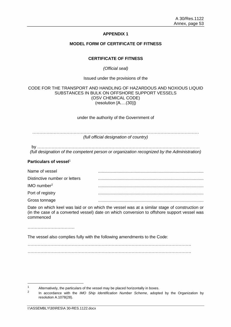
A 30/Res.1122 Annex, page 53
I:\ASSEMBLY\30\RES\A 30-RES.1122.docx
APPENDIX 1
MODEL FORM OF CERTIFICATE OF FITNESS
CERTIFICATE OF FITNESS
(Official seal)
Issued under the provisions of the CODE FOR THE TRANSPORT AND HANDLING OF HAZARDOUS AND NOXIOUS LIQUID
SUBSTANCES IN BULK ON OFFSHORE SUPPORT VESSELS (OSV CHEMICAL CODE)
(resolution [A.…(30)])
under the authority of the Government of
……………………………………………………………………………………………………… (full official designation of country)
by ……………………………………………………………………………………………………
(full designation of the competent person or organization recognized by the Administration) Particulars of vessel1
Name of vessel .......................................................................................
Distinctive number or letters .......................................................................................
IMO number2 .......................................................................................
Port of registry .......................................................................................
Gross tonnage .......................................................................................
Date on which keel was laid or on which the vessel was at a similar stage of construction or (in the case of a converted vessel) date on which conversion to offshore support vessel was commenced …………………………… The vessel also complies fully with the following amendments to the Code:
…………………………………………………………………………………………………….
…………………………………………………………………………………………………….
1 Alternatively, the particulars of the vessel may be placed horizontally in boxes. 2 In accordance with the IMO Ship Identification Number Scheme, adopted by the Organization by
resolution A.1078(28).

A 30/Res.1122 Annex, page 54
I:\ASSEMBLY\30\RES\A 30-RES.1122.docx
The vessel is exempted from compliance with the following provisions of the Code:
…………………………………………………………………………………………………….
…………………………………………………………………………………………………….
THIS IS TO CERTIFY: 1 That the vessel has been surveyed in accordance with the provisions of 1.4 of the Code; 2 That the survey showed that the construction and equipment of the vessel and the
condition thereof are in all respects satisfactory and that the vessel complies with the relevant provisions of the Code;
3 That the vessel has been provided with a Manual in accordance with appendix 4 of
Annex II of MARPOL as called for by regulation 14 of Annex II, and that the arrangements and equipment of the vessel prescribed in the Manual are in all respects satisfactory;
4 That the vessel meets the requirements for the carriage in bulk of the following
products, provided that all relevant operational requirements of the Code and MARPOL Annex II are observed:
Product Conditions of carriage (tank numbers, etc.)
Pollution Category
Continued on attachment 1, additional signed and dated sheets.3 Tank numbers referred to in this list are identified on attachment 2, signed and dated tank plan.
5 That, in accordance with 1.3, the provisions of the Code are modified in respect of the
vessel in the following manner:
……………………………………………………………………………………………………. 6 That the vessel should be loaded:
.1 in accordance with the loading conditions provided in the approved loading manual, stamped and dated........................ and signed by a responsible officer of the Administration, or of an organization recognized by the Administration3;
.2 in accordance with the loading limitations appended to this Certificate.3
3 Delete as appropriate.

A 30/Res.1122 Annex, page 55
I:\ASSEMBLY\30\RES\A 30-RES.1122.docx
Where it is required to load the vessel other than in accordance with the above instruction, the necessary calculations to justify the proposed loading conditions should be communicated to the certifying Administration who may authorize in writing the adoption of the proposed loading condition.4
This Certificate is valid until (dd/mm/yyyy) ……………………………...…………………………5 subject to surveys in accordance with 1.4 of the Code. Completion date of the survey on which this certificate is based: .............................................. (dd/mm/yyyy)
Issued at ….………………………………………………… (Place of issue of certificate)
…………………… (Date of issue)
……………………………………………… (Signature of authorized official
issuing the certificate)
(Seal or stamp of the authority, as appropriate) Notes on completion of Certificate: 1 The Certificate can be issued only to vessels entitled to fly the flags of States which
are both a Contracting Government to SOLAS and a Party to MARPOL. 2 Products: products listed in 1.1.9 of the Code, or which have been evaluated by the
Administration in accordance with 1.1.10 of the Code should be listed. In respect of the latter "new" products, any special provisions provisionally prescribed should be noted.
3 Products: the list of products the vessel is suitable to carry should include the noxious
liquid substances of category Z which are not covered by the IBC Code and should be identified as "IBC Code chapter 18 Category Z".
4 Instead of being incorporated in the Certificate, this text may be appended to the Certificate if signed and
stamped. 5 Insert the date of expiry, as specified by the Administration, which should not exceed 5 years from the date
of initial survey or the periodical survey.

A 30/Res.1122 Annex, page 56
I:\ASSEMBLY\30\RES\A 30-RES.1122.docx
ENDORSEMENT FOR ANNUAL AND INTERMEDIATE SURVEYS THIS IS TO CERTIFY that at a survey required by 1.5.2 of the IBC Code the vessel was found to comply with the relevant provisions of the Code. Annual survey: Signed
(Signature of duly authorized official)
Place
Date (dd/mm/yyyy) (Seal or stamp of the Authority, as appropriate) Annual/Intermediate3 survey: Signed
(Signature of duly authorized official)
Place
Date (dd/mm/yyyy) (Seal or stamp of the Authority, as appropriate) Annual/Intermediate3 survey: Signed
(Signature of duly authorized official)
Place
Date (dd/mm/yyyy) (Seal or stamp of the Authority, as appropriate) Annual survey: Signed
(Signature of duly authorized official)
Place
Date (dd/mm/yyyy) (Seal or stamp of the Authority, as appropriate)
3 Delete as appropriate.
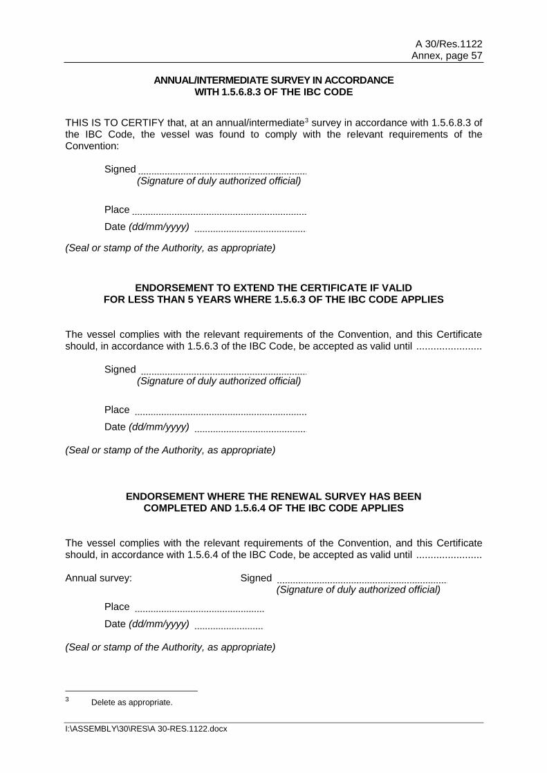
A 30/Res.1122 Annex, page 57
I:\ASSEMBLY\30\RES\A 30-RES.1122.docx
ANNUAL/INTERMEDIATE SURVEY IN ACCORDANCE WITH 1.5.6.8.3 OF THE IBC CODE
THIS IS TO CERTIFY that, at an annual/intermediate3 survey in accordance with 1.5.6.8.3 of the IBC Code, the vessel was found to comply with the relevant requirements of the Convention:
Signed (Signature of duly authorized official)
Place
Date (dd/mm/yyyy)
(Seal or stamp of the Authority, as appropriate)
ENDORSEMENT TO EXTEND THE CERTIFICATE IF VALID FOR LESS THAN 5 YEARS WHERE 1.5.6.3 OF THE IBC CODE APPLIES
The vessel complies with the relevant requirements of the Convention, and this Certificate should, in accordance with 1.5.6.3 of the IBC Code, be accepted as valid until .......................
Signed (Signature of duly authorized official)
Place
Date (dd/mm/yyyy) (Seal or stamp of the Authority, as appropriate)
ENDORSEMENT WHERE THE RENEWAL SURVEY HAS BEEN COMPLETED AND 1.5.6.4 OF THE IBC CODE APPLIES
The vessel complies with the relevant requirements of the Convention, and this Certificate should, in accordance with 1.5.6.4 of the IBC Code, be accepted as valid until ....................... Annual survey: Signed
(Signature of duly authorized official)
Place
Date (dd/mm/yyyy) (Seal or stamp of the Authority, as appropriate)
3 Delete as appropriate.

A 30/Res.1122 Annex, page 58
I:\ASSEMBLY\30\RES\A 30-RES.1122.docx
ENDORSEMENT TO EXTEND THE VALIDITY OF THE CERTIFICATE UNTIL REACHING THE PORT OF SURVEY OR FOR A PERIOD
OF GRACE WHERE 1.5.6.5 OR 1.5.6.6 OF THE IBC CODE APPLIES This Certificate should, in accordance with 1.5.6.5/1.5.6.63 of the IBC Code, be accepted as valid until
Signed (Signature of duly authorized official)
Place
Date (dd/mm/yyyy) (Seal or stamp of the Authority, as appropriate)
ENDORSEMENT FOR ADVANCEMENT OF ANNIVERSARY DATE WHERE 1.5.6.8 OF THE IBC CODE APPLIES
In accordance with 1.5.6.8 of the IBC Code, the new anniversary date is
Signed (Signature of duly authorized official)
Place
Date (dd/mm/yyyy) (Seal or stamp of the Authority, as appropriate) In accordance with 1.5.6.8 of the IBC Code, the new anniversary date is
Signed (Signature of duly authorized official)
Place
Date (dd/mm/yyyy) (Seal or stamp of the Authority, as appropriate)
3 Delete as appropriate.
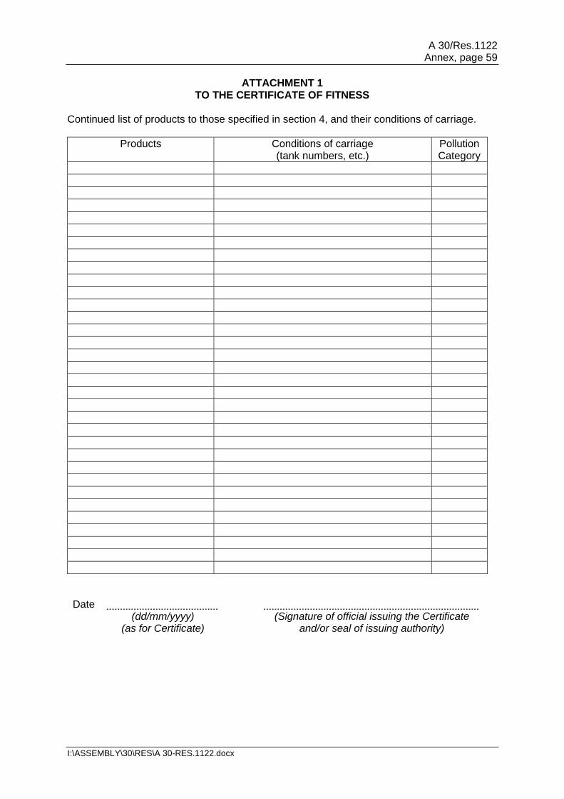
A 30/Res.1122 Annex, page 59
I:\ASSEMBLY\30\RES\A 30-RES.1122.docx
ATTACHMENT 1 TO THE CERTIFICATE OF FITNESS
Continued list of products to those specified in section 4, and their conditions of carriage.
Products Conditions of carriage (tank numbers, etc.)
Pollution Category
Date
(dd/mm/yyyy) (as for Certificate)
(Signature of official issuing the Certificate and/or seal of issuing authority)

A 30/Res.1122 Annex, page 60
I:\ASSEMBLY\30\RES\A 30-RES.1122.docx
ATTACHMENT 2 TO THE CERTIFICATE OF FITNESS
TANK PLAN (specimen) Name of vessel:
Distinctive number or letters:
Date
(dd/mm/yyyy) (as for Certificate)
(Signature of official issuing the Certificate and/or seal of issuing authority)

A 30/Res.1122 Annex, page 61
I:\ASSEMBLY\30\RES\A 30-RES.1122.docx
APPENDIX 2
GUIDELINES FOR TESTING PRIOR TO BACKLOADING 1 General 1.1 The results of these tests will allow the master, through confirmation with the attached checklist, to establish if the backload is acceptable for carriage on board the vessel. Acceptance is based on the reported analytical data and the measured physical properties, the known nature of the chemical composition and the previous cargo carried in the vessel's tanks. A generic risk assessment should be available on board the vessel and updated when new information and circumstances become apparent. Offshore installation crew should be aware that in certain circumstances the master of the vessel may require advice from the vessel's onshore technical advisers and that a response from onshore may take time to receive. 1.2 Recognizing the relatively complex nature of the cargo, the material intended for backloading should be subject to a series of test to provide an indicative overview of the constituent composition and reactive properties of the material. 1.3 The tests carried out prior to backloading should reflect the conditions in the vessels tanks, that is to say there will be no agitation and no forced ventilation unless specifically required or requested. 1.4 If there is any doubt regarding the result of the test, the test should be repeated and reviewed. 2 Testing prior to backloading 2.1 Flashpoint The minimum acceptable flashpoint of 60°C (Pensky-Martens closed cup method or equivalent) is applicable to wet bulk waste. Sampling should be set up to detect the worst case situation, particularly where there is potential for crude oil or condensate contamination where the oil will rise to the surface of the tank. Base oils typically have flashpoints in the range of 70 to 100°C. If the only oil component in a bulk waste is base oil then the flashpoint cannot be lower than that of the base oil itself. If the flashpoint is relatively low (60 to 70°C) an explanation should be provided before the analysis form is presented to the vessel's master. Prior to sampling, the material should be left without agitation for at least 30 min and then surface sampled. 2.2 Lower Explosive Limit (LEL) The LEL gas detector will confirm potential flashpoint issues. The noxious gas test is modified to simulate the unvented vessel's tanks. The sample is placed in a closed container with a sampling port on top and left to equilibrate for 30 min. A tube is then connected from the port to the gas analyser and the sample is analysed. The flashpoint and LEL results should be consistent with each other. LEL gas meters are normally set so that the alarm goes off in the range of 10 to 20% LEL methane equivalent. Any number above 25% would be considered high. Other gases potentially present can have a different LEL range than methane.

A 30/Res.1122 Annex, page 62
I:\ASSEMBLY\30\RES\A 30-RES.1122.docx
2.3 Hydrogen sulphide (H2S) 2.3.1 H2S most commonly arises from the activity of sulphate reducing bacteria (SRB). SRB will become active provided there is a "food" source and low oxygen conditions. This would be typical of stagnant oil-contaminated fluid stored for a long time. H2S is an extremely poisonous gas which is heavier than air. The maximum exposure limit is 10 ppm over an 8 hour period. Offshore sensors and routine offshore analysis methods will detect if H2S is a potential problem in backloads. In the event of a positive test another sample should be collected to confirm the result. If this second result is positive further work may be required to determine the source of the H2S. The sample should be taken from below the surface of the unagitated tank. Most oil will be in the top layer and will give a worst case oil content.
2.3.2 As a precaution, treatment of the material may be required. The SRB organisms thrive in a pH range of 5.5 to 8.0. The lower the pH the greater the breakout of H2S. The backload can be treated on the installation to prevent breakout of H2S in the vessel tanks. Biocides kill the bacteria but do not remove dissolved H2S. H2S scavengers will remove dissolved H2S but do not stop biological activity. Caustic soda will raise the pH and prevent H2S gas breakout. In the event that H2S is detected, tests should be carried out offshore to determine the best treatment prior to backloading. After treatment a final H2S test should be carried out to confirm zero H2S and noted on the analysis form before the hose is connected to the vessel for backloading. 2.4 pH The pH of seawater is typically 8.3. Oil mud is alkaline and could raise the pH slightly. Cement contaminant is highly alkaline. In general alkaline pH (above 7) protects from corrosion. Highly alkaline materials can be caustic and require care in handling. Cement and sodium silicate can lead to high pH value. Low pH (less than 4) is highly acidic and an explanation should be provided on the analysis form. Acids such as citric acid or acidic chemicals such as hydrochloric acid can lead to low pH. It should be noted that pH less than 9 means that H2S will already have broken out as a gas. 2.5 Retort analysis (solids, water, oil volume %) This should match the estimated composition (volume %) on the analysis form. It should be noted that it may be difficult to get representative samples if the liquid tends to separate. Some divergence is expected, for example if oil is noted as 5%, the range could be 3 to 10%. If separation is likely a range is preferred, for example 5 to 10%. The solids component can form a residue in the vessel tank and be a potential location for SRB activity and H2S. 2.6 Specific gravity (SG) The specific gravity of common water-based fluids cover the range of 1.03 (seawater), sodium chloride (1.2), and calcium chloride (1.33). Rarely used brines such as caesium formate can reach an SG of 2.2. Oil mud is typically 1.1 to 1.5, but can exceed 2.0. Mixtures will have intermediate values, most tending towards 1.03 as seawater is the major component. It should be noted that if mixtures separate the top half can have a different density than the bottom half.

A 30/Res.1122 Annex, page 63
I:\ASSEMBLY\30\RES\A 30-RES.1122.docx
EXAMPLE OF THE ANALYSIS FORM6
TO BE COMPLETED AND PROVIDED TO OSV MASTER PRIOR TO BACKLOADING
Sample description
Sample reference
Vessel Date
Offshore asset Producer
Well name & number
Waste company
Total number of barrels
Waste note number
WASTE COMPONENTS
Component name
Concentration Units MSDS available
% Volume
% Volume
% Volume
% Volume
% Volume
% Volume
% Volume
% Volume
LABORATORY ANALYSIS RESULTS
Test Method Units Results Range of results / Guidance
Salinity (Chloride)
Titration mg / l
Flashpoint Closed cup flashpoint
ºC
Should be >60ºC to backload If flashpoint is low (<70ºC) then explanation should be provided
6 Refer to the Guidelines for Offshore Marine Operations (GOMO), developed by a group of organizations,
and other industry standards and best practices.

A 30/Res.1122 Annex, page 64
I:\ASSEMBLY\30\RES\A 30-RES.1122.docx
TO BE COMPLETED AND PROVIDED TO OSV MASTER PRIOR TO BACKLOADING
Gas test (H2S)
Gas meter
ppm Should be zero Indication of bacterial activity
Gas test (LEL) %
<25%, ideally zero. Meter alarm typically set to 10-20% LEL. Should be consistent with flashpoint
Gas test (Oxygen)
%
pH pH meter
4-11 is acceptable range for OSV tank coatings. SHOULD be 9.5-10.5 to keep any H2S in solution
Water Retort % Volume
Oil content Retort % Volume
Confirm retort report agrees with appendix 10 – F, Section 4 components and waste consignment note
Solids Retort % Volume
Confirm retort report agrees with appendix 10 – F, Section 4 components and waste consignment note
Bulk specific gravity
SG <2.5 If >2.5 seek further guidance on vessel capability
Appearance
Odour
Date and time of analysis
CONCLUSIONS
Analysis to be conducted by person competent to do so Comments (Yes / No / Details)
This liquid has been analysed as per GOMO appendix 10 – F and it is my opinion that it is safe for carriage in a standard clean OSV bulk tank.
This liquid has been analysed as per GOMO appendix 10 – F and will be loaded into a tank with residues / existing cargo. Compatibility has been risk assessed and found to be safe for carriage.

A 30/Res.1122 Annex, page 65
I:\ASSEMBLY\30\RES\A 30-RES.1122.docx
TO BE COMPLETED AND PROVIDED TO OSV MASTER PRIOR TO BACKLOADING
H2S Avoidance
Details of mandatory wet bulk waste treatment with biocide (chemical / quantity)
Details of wet bulk waste treatment in order to produce pH of between 9.5 and 10.5 (chemical / quantity)
Has waste handling facility been informed of volume and ETA onshore? (Yes / No)
Does the waste handling facility have the capability to take off the waste at the first port call? (Yes / No)
Name Signature Date
Analyst
Operations Representative

A 30/Res.1122 Annex, page 66
I:\ASSEMBLY\30\RES\A 30-RES.1122.docx
APPENDIX 3
MODEL FORMAT FOR THE PROCEDURE FOR DISCHARGING AND LOADING PORTABLE TANKS CONTAINING DANGEROUS GOODS CARRIED AS DECK TANKS
ON OFFSHORE SUPPORT VESSELS
Table of contents 1 Purpose 2 Application 3 References, definitions and responsibilities 4 Description of the deck spread equipment and arrangements
.1 General arrangements of deck spread
.2 Discharging and loading operations for portable tanks
.3 Additional operational information
Attachments: 1 Summary covering description of intended offshore campaign 2 Related discharge permits from local water jurisdictions 3 Material safety data sheets 4 Sea fastening arrangements and calculations 5 Deck arrangements and pipeline drawing 6 Portable tank information and details
1 PURPOSE 1.1 The purpose of this Procedure is to identify the arrangements and equipment required to enable compliance with MARPOL Annex II and the IMDG Code, and to identify for the vessel's officers all operational procedures with respect to cargo handling, tank cleaning, slops handling, ballasting and deballasting which should be followed in order to comply with the requirements of MARPOL Annex II. 1.2 This Procedure covers all marine transportation aspects of the shipment for the products identified in the cargo list of the Certificate of Fitness issued, and in accordance with chapter 16 of the present Code describing the provisions for loading, sea passage, offshore discharge, return voyage and subsequent unloading of those tanks to shore. 1.3 This Procedure should include:
.1 a summary giving a description of the intended offshore campaign; .2 related discharge permits from local water jurisdictions; .3 material safety data sheets; .4 sea fastening arrangements and calculations; .5 deck arrangements and pipeline drawing; and .6 portable tank information and details.

A 30/Res.1122 Annex, page 67
I:\ASSEMBLY\30\RES\A 30-RES.1122.docx
2 APPLICATION This Procedure applies to all personnel on OSVs involved in the handling and discharging or loading of the products listed in the cargo list of the Certificate of Fitness issued, and in accordance with chapter 17 of the present Code. It is intended to be an informative document for those involved in the safe management of the installed deck spread and for the Administration concerned with enforcing safe working practices while these operations are being conducted. 3 REFERENCES, DEFINITIONS AND RESPONSIBILITIES 3.1 References The proposed operations should be carried out in accordance with the following:
.1 International Maritime Dangerous Goods Code (IMDG Code), as amended
The IMDG Code, as amended, is used as a basis for national regulations in pursuance of their obligation under SOLAS chapter VIII and MARPOL Annex III. Observance of the Code harmonizes the practices and procedures followed in the carriage of dangerous goods by sea and ensures compliance with the mandatory requirements of SOLAS and MARPOL Annex III.
.2 Guidelines for the design and construction of offshore supply vessels, 2006
These Guidelines have been developed for the design and construction of new offshore supply vessels with a view to promoting the safety of such vessels and their personnel, recognizing the unique design features and service characteristics of these vessels. The Guidelines furthermore provide a standard of safety equivalent to the relevant requirements of SOLAS, and in particular to the stability criteria of the International Code on Intact Stability, 2008 (2008 IS Code), as amended.
.3 International Code for the Construction and Equipment of Ships Carrying Dangerous Chemicals in Bulk (IBC Code) The IBC Code was adopted by the Marine Environment Protection Committee of the Organization by resolution MEPC.19(22), as amended, provided that such amendments were adopted and brought into force in accordance with the requirements of article 16 of MARPOL concerning amendment procedures applicable to an appendix to an annex.
.4 Code for the Transport and Handling of Hazardous and Noxious Liquid Substances in Bulk on Offshore Support Vessels (OSV Chemical Code)
3.2 Definitions 3.2.1 Dangerous goods are those substances (including mixtures and solutions) and articles subject to the requirements of the IMDG Code assigned to one of the Classes 1-9 according to the hazard or the most predominant of the hazards present.

A 30/Res.1122 Annex, page 68
I:\ASSEMBLY\30\RES\A 30-RES.1122.docx
3.2.2 Marine pollutants are environmentally hazardous substances identified as marine pollutants in the IMDG Code, are considered a threat to marine life, and are carried under the requirements of MARPOL Annex III. 3.3 Responsibilities 3.3.1 The OSV should be in compliance with section 17.3 of the present Code. 3.3.2 Master: The master of the supply vessel involved in the transportation is responsible for all activities carried out on his or her vessel. The master has the authority to stop any operation he or she considers to be unsafe, that puts personnel or the vessel at risk or that could pollute the environment. 3.3.3 Specialist operator: The specialist operator, if required, will be the person/contractor responsible for the cargo transfer operations with regards to the deck spread. He or she will be additional to the normal vessel crew, and directly responsible to the master. 4 DESCRIPTION OF THE DECK SPREAD EQUIPMENT AND ARRANGEMENTS 4.1 General arrangements of deck spread 4.1.1 This should contain a brief description of the cargo deck area of the vessel with the main features of the portable tanks and their positions on the deck taking into consideration the definition of "cargo area" in 1.2.7 of the present Code. 4.1.2 A brief description of the physical arrangements for the securing of the portable tanks, pipelines and other equipment to the deck of the vessel should also contain details of deck protection systems, etc. 4.1.3 Description of deck spread pumping and piping arrangements This section should contain a description of the pumping and piping arrangements. Line or schematic drawings should be provided showing the following and be supported by textual explanation where necessary:
.1 cargo piping arrangements with diameters; .2 cargo piping arrangements that cross-connect to the vessel's bulk tanks; .3 cargo pumping arrangements with pump capacities; .4 location of suction points of cargo lines and valve position for every portable
tank; .5 stripping or blowing back arrangements; .6 quantity and pressure of nitrogen or carbon dioxide required for line blowing
and inerting if applicable; and .7 tank ventilation arrangements and position of vent outlets, etc.

A 30/Res.1122 Annex, page 69
I:\ASSEMBLY\30\RES\A 30-RES.1122.docx
4.1.4 Description of the portable tank ventilation systems
This section should contain a description of the portable tank ventilation system and details to prevent accumulation of vapours on the deck area, based on the properties of the tank contents. 4.1.5 Description of securing arrangements of tanks and pipelines This section should contain a description of securing arrangements of tanks and pipelines. 4.2 Discharging and loading operations for portable tanks This section should contain a description of and operational procedures for the loading and discharging of the portable tank while on board the vessel and they are supported by text regarding the following:
.1 inerting systems if required when carrying low-flashpoint products; .2 suitable fire-fighting media determined to be effective for the substance being
carried will be provided and available for immediate use during the transfer operation;
.3 spillage clean up material specific to the substance, if required, is available
in the event of an incident; .4 personal protective equipment, if required, will be provided for the operator
loading the portable tank; this will be worn at all times, by those involved, during cargo handling operations; equipment supplied should be in addition to equipment required when carrying dangerous goods; and
.5 emergency procedures in the event of an incident.
4.3 Additional operational information This section should contain additional details and a description of the operational procedures involved when the deck spread is in operation and should cover the following points:
.1 procedures to be followed in the event of a spillage and the disposal of the clean-up material;
.2 details of the blowback system and whether the residues are to be blown to
the installation or to the tanks on deck; .3 details of the process that will be carried out on board when the deck spread
is in operation; .4 emergency shut-down procedures for the deck spread; and .5 details of the hose coupling arrangements to the installation and method of
quick release.

A 30/Res.1122 Annex, page 70
I:\ASSEMBLY\30\RES\A 30-RES.1122.docx
Attachments: The following attachments should be prepared:
1. summary covering description of intended offshore campaign; 2. related discharge permits from local water jurisdictions; 3. material safety data sheets; 4. sea fastening arrangements and calculations; 5. deck arrangements and pipeline drawing; and 6. portable tank information and details.
___________