resistive earth fault analyser; - WIT Press · substation, which affect the auto-reclosing...
12
Substation automation and control in railway networks L. Ippolito*, F. Murolo*, A. Piccolo*, D. Villaccf "Dipartimento di Ingegneria dell 'Informazione edlngegneria Elettrica, Universita degli Studi di Salerno, Salerno, Italy SEPSA - Societa Concessionaria Pubblici Servizi Ferroviari e Automobilistici S.p.A, Napoli, Italy ^Dipartimento di Ingegneria Elettrica, Universita degli Studi di Cassino, Cassino (FR), Italy Abstract This paper introduces an approach to railway substation automation and protection. Itshows, after a briefly description of the typical railway substation structures, the concept of the railway substations equipped with an innovative telecontrol and automation system. In this paper the traditional protective and operative functions, which can be automated, will be pointed out and a possible automation system will be discussed in detail. Then some considerations will be made about the potentialbenefits and costs associated with those automated functions. 1. Introduction Today, many studies on automation of electrical substation are present in literature, describing the possibility to achieve such advantages as system safety or energy saving with an innovative and intelligent management of electric power plants. On the other hand, the progressive development of the control and protection systems towards distributed intelligencepermits their adoption also in traditional electric power plants as traction ones. The study of the present state reveals that many substations of the various national entity for railway transportation are equipped only with classic automation equipments: • automatic reclosing; Transactions on the Built Environment vol 18, © 1996 WIT Press, www.witpress.com, ISSN 1743-3509
Transcript of resistive earth fault analyser; - WIT Press · substation, which affect the auto-reclosing...
Substation automation and control in railway
networks
L. Ippolito*, F. Murolo*, A. Piccolo*, D. Villaccf
"Dipartimento di Ingegneria dell 'Informazione edlngegneria
Elettrica, Universita degli Studi di Salerno, Salerno, Italy
SEPSA - Societa Concessionaria Pubblici Servizi Ferroviari e
Automobilistici S.p.A, Napoli, Italy
Dipartimento di Ingegneria Elettrica,
Universita degli Studi di Cassino, Cassino (FR), Italy
Abstract
This paper introduces an approach to railway substation automation andprotection. It shows, after a briefly description of the typical railway substationstructures, the concept of the railway substations equipped with an innovativetelecontrol and automation system. In this paper the traditional protective andoperative functions, which can be automated, will be pointed out and a possibleautomation system will be discussed in detail. Then some considerations willbe made about the potential benefits and costs associated with those automatedfunctions.
1. Introduction
Today, many studies on automation of electrical substation are present inliterature, describing the possibility to achieve such advantages as system safetyor energy saving with an innovative and intelligent management of electricpower plants. On the other hand, the progressive development of the controland protection systems towards distributed intelligence permits their adoptionalso in traditional electric power plants as traction ones.
The study of the present state reveals that many substations of the variousnational entity for railway transportation are equipped only with classicautomation equipments:
• automatic reclosing;
Transactions on the Built Environment vol 18, © 1996 WIT Press, www.witpress.com, ISSN 1743-3509
128 Computers in Railways
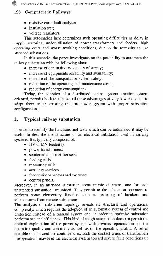
• resistive earth fault analyser;• insulation test;• voltage regulators.This automation lack determines such operating difficulties as delay in
supply restoring, underutilisation of power transformers and feeders, highoperating costs and worse working conditions, due to the necessity to useattended substations.
In this scenario, the paper investigates on the possibility to automate therailway substation with the following aims:
• increase of continuity and quality of supply;• increase of equipments reliability and availability;• increase of the transportation system safety;• reduction of the operating and maintenance costs;• reduction of energy consumptions.Today, the adoption of a distributed control system, traction system
oriented, permits both to achieve all these advantages at very low costs and toadapt them to an existing traction power system with proper substationconfigurations.
2. Typical railway substation
In order to identify the functions and tests which can be automated it may beuseful to describe the structure of an electrical substation used in railwaysystems. It is typically composed of:
# HV or MV feeder(s);• power transformers;• semiconductor rectifier sets;• feeding cells;• measuring cells;• auxiliary services;• feeder disconnectors and switches;• control panels.
Moreover, in an attended substation some mimic diagrams, one for eachunattended substation, are added. They permit to the substation operators toperform some elementary function such as reclosing of breakers andtelemeasures from remote substations.The analysis of substation topology reveals its structural and operationalcomplexity, which requires the adoption of an automatic system of control andprotection instead of a manual system one, in order to optimise substationperformance and efficiency. This kind of rough automation does not permit theoptimal exploitation of the power system with obvious repercussions on theoperation quality and continuity as well as on the operating profits. A set ofcredible or non-credible contingencies, such the contact wires or transformersmisoperation, may lead the electrical system toward severe fault conditions up
Transactions on the Built Environment vol 18, © 1996 WIT Press, www.witpress.com, ISSN 1743-3509
Computers in Railways 129
to the system outage, to which corresponds a lowering of the plant safety index.This means that the traditional control and protection systems are not able
to manage such contingencies both owing to short reaction and evaluationtimes are required and because of these systems cannot guarantee the respect ofprefixed indices of security and safety. The need to respect, according topriority, a prefixed index of security for humans (passengers and manpower)and a prefixed index of safety for plants and components precludes the chanceto demand the power system restoration and reconfiguration to a humanoperator, giving to the automated system the task to modify the traction systemoperation, in presence of failure conditions, in order to guarantee the respect ofthe safety and security indices under the operator supervision.
Still from the point of view of an higher and higher reliability andavailability of the system, it must be observed that the adoption of anautomated system may represent a useful tool for a preventive maintenance,based on electric plant statistics, supporting high availability of each monitoredequipment.
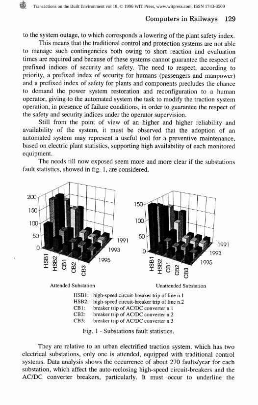
The needs till now exposed seem more and more clear if the substationsfault statistics, showed in fig. 1, are considered.
1991
1993
1995
19911993
1995
Attended Substation Unattended Substation
HSB1: high-speed circuit-breaker trip of line n. 1HSB2: high-speed circuit-breaker trip of line n.2CB1: breaker trip of AC/DC converter n. 1CB2: breaker trip of AC/DC converter n.2CB3: breaker trip of AC/DC converter n.3
Fig. 1 - Substations fault statistics.
They are relative to an urban electrified traction system, which has twoelectrical substations, only one is attended, equipped with traditional controlsystems. Data analysis shows the occurrence of about 270 faults/year for eachsubstation, which affect the auto-reclosing high-speed circuit-breakers and theAC/DC converter breakers, particularly. It must occur to underline the
Transactions on the Built Environment vol 18, © 1996 WIT Press, www.witpress.com, ISSN 1743-3509
130 Computers in Railways
elimination of these faults has required the manual intervention of the operatorin substation, and the fault clearing time may vary from some minutes to somehours (a 7h 34min interruption has been registered), during which the operationis reduced or stopped with consequent operating loss.
Relatively to the short time interruptions (up to 2 minutes), they are notrecorded and are eliminated by the auto-reclosure of the high-speed circuit-breakers, under the substation operators supervision, in order to avoid thebreakers of the unattended substation are locked. In fact, If this happens it isnecessary a local intervention to unlock the breakers, with an obvious increaseof the fault clearing time.
The trip of the high-speed circuit-breakers, which protect the contactwires from overcurrents, is the most recurring event in the examined systembecause it depends both to short circuits on the wires or on-board trains and tothe trains starting currents. On the other hand, if the setting of the high-speedcircuit-breakers is not optimal it can cause untimely breaker trips withconsequent disconnection of the contact wire, for this reason they requiresperiodic off-line inspection to check the relay functions in order to minimisethis occurrence.The duration and the high frequency of the aforementioned faults reveal theimportance to single out the control and protection functions which are possibleto automate for a better exploitation of the existing components and plants.
3 Automation function description
As aforementioned, the spreading of automation in railway substations mayimprove their control and maintenance and facilitate the monitoring. The firstfundamental step in the design of an integrated substation control system is tomake a list of functions to be automated. On this basis it is possible to considerthe following functional modules which can be included in the automationsystem [1]:
• the control module, which performs substation switch controlfunctions both in normal state and during restoration period;
• the monitoring module, which performs an intelligent monitoring fordigital and analog parameters, giving alarm signals if one of themexceeds the normal state limitations;
• the protection module, which performs the misoperations diagnosis,using the informations coming from circuit breakers and protectiverelays, and the fault location function;
• the logging module, which draws up a complete and detailed report ofsubstation plant, specifying the kind of faults, the equipments affectedby faults, the fault clearing times, etc. .
All the functions, using data stored in one or more data banks, can beautomated and classified in function of the performed operation as showed intab. I.
Transactions on the Built Environment vol 18, © 1996 WIT Press, www.witpress.com, ISSN 1743-3509
Computers in Railways 131
Table I - Functions to be automated.
Control remote trip, close and protection resetautomatic reclosingservice restoration
Monitoring circuit breaker statustrip coil monitoringload tap changerstransformerscircuit breaker and protection alarms;feeder loadsdiagnostic (local and remote)substation reactive power monitoring
Protection inverse time and instantaneous overcurrentbusbar protectionearth faultthermal imagingbreaker failurefault locationfault isolation
Logging protection, circuit breaker operating, and faultclearing timesload and fault currents
All these functions, for their complexity, diversity and interactions,require a detailed description. To the aim to obtain a suitable description of thesubstation automation functions, some representation methods could beadopted, among which the more efficient one appears the Petri net method [2].It permits to represent a function as a "states machine" and to simulate allfunctions evolving in parallel mode, obtaining such advantages as theprogramming work reduction, debugging effort reduction, softwaredocumentation optimisation, etc. . In particular, this method of analysissimplify the testing stage as the Petri nets furnish an exhaustive methodology toidentify the "critical stages" of each functions. Moreover, this methodologypermits to convert the specifications directly into software program for PLCs,using literal languages which simplify the future software maintenance and thetraining of the maintenance staff.
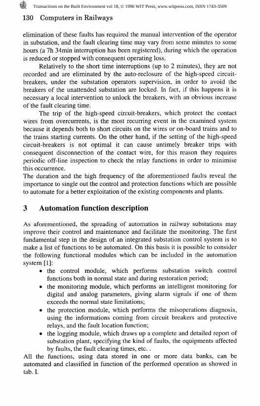
Relatively to the architecture for this control system the choice among thepossible schemes must be made on the base of operational, reliability and costsconsiderations. In any case it must respect such demands as modular structureand locally distributed intelligence. A possible architecture for an integratedcontrol system is reported in fig. 2.
Transactions on the Built Environment vol 18, © 1996 WIT Press, www.witpress.com, ISSN 1743-3509
132 Computers in Railways
Levels of control
System level
Substation level
Bay level
System control
Rl U protection MMI
RTU: Remote Terminal UnitMMI: Man-Machine InterfaceDACU: Data Acquisition and Control
Unit
Fig. 2 - Control system architecture.
This architecture permits to have an high availability, through selfdiagnostics and automatic fault detection, and an improved life cycle cost,deriving from reduced installation and maintenance costs [3].
A subsequent step in the direction of an higher efficiency andoptimisation of plants, is to have a control system with the ability of saving theknowledge and heuristics accumulated from the past. One of the main aspectsin substation automation and control is an expedient return-to-service followinga system failure, so during the restoration from a fault, fast and correctoperations are required. Actually, only the knowledge accumulated by the oldexperienced operators permits to face severe fault conditions. Thus, to preservethis ability also after their retirement, it is desired to develop an operation andmaintenance system able to support the operators to do their tasks in shortertime and easier [4]. This ability can be performed only by new control systemsbased on expert system and/or fuzzy logic and/or neural network techniques.They have some functional characteristics able to simplify the operation andmaintenance activity, as:
• ability to preserve the knowledge and heuristics accumulated from thepast;
• ability to enlarge the base of knowledge easily.This characteristics permits to obtain such advantages as quick
restoration, relieving operators from the stress, reduction of manpower forroutine operations, higher safety in restoration actions, higher diagnostic level,etc. .
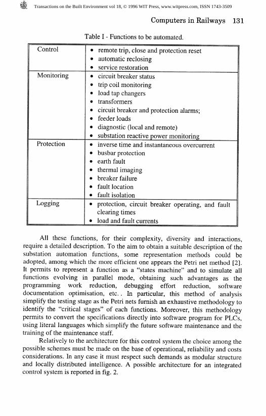
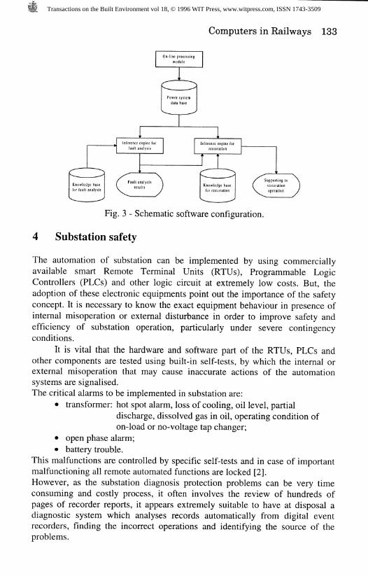
A possible schematic software configuration for the control system expertsystem based for operation and maintenance of substations [4] is showed infig.3.
Transactions on the Built Environment vol 18, © 1996 WIT Press, www.witpress.com, ISSN 1743-3509
Computers in Railways 133
On line processmodule
ing
>
Inferencefault a
.ngine for
nalysisi
Inference engine forrestoration
J 'f >
| Knowledge hasfor restoration
Fig. 3 - Schematic software configuration.
4 Substation safety
The automation of substation can be implemented by using commerciallyavailable smart Remote Terminal Units (RTUs), Programmable LogicControllers (PLCs) and other logic circuit at extremely low costs. But, theadoption of these electronic equipments point out the importance of the safetyconcept. It is necessary to know the exact equipment behaviour in presence ofinternal misoperation or external disturbance in order to improve safety andefficiency of substation operation, particularly under severe contingencyconditions.
It is vital that the hardware and software part of the RTUs, PLCs andother components are tested using built-in self-tests, by which the internal orexternal misoperation that may cause inaccurate actions of the automationsystems are signalised.The critical alarms to be implemented in substation are:
• transformer: hot spot alarm, loss of cooling, oil level, partialdischarge, dissolved gas in oil, operating condition ofon-load or no-voltage tap changer;
• open phase alarm;• battery trouble.
This malfunctions are controlled by specific self-tests and in case of importantmalfunctioning all remote automated functions are locked [2].However, as the substation diagnosis protection problems can be very timeconsuming and costly process, it often involves the review of hundreds ofpages of recorder reports, it appears extremely suitable to have at disposal adiagnostic system which analyses records automatically from digital eventrecorders, finding the incorrect operations and identifying the source of theproblems.
Transactions on the Built Environment vol 18, © 1996 WIT Press, www.witpress.com, ISSN 1743-3509
134 Computers in Railways
5 Substation availability and maintenance
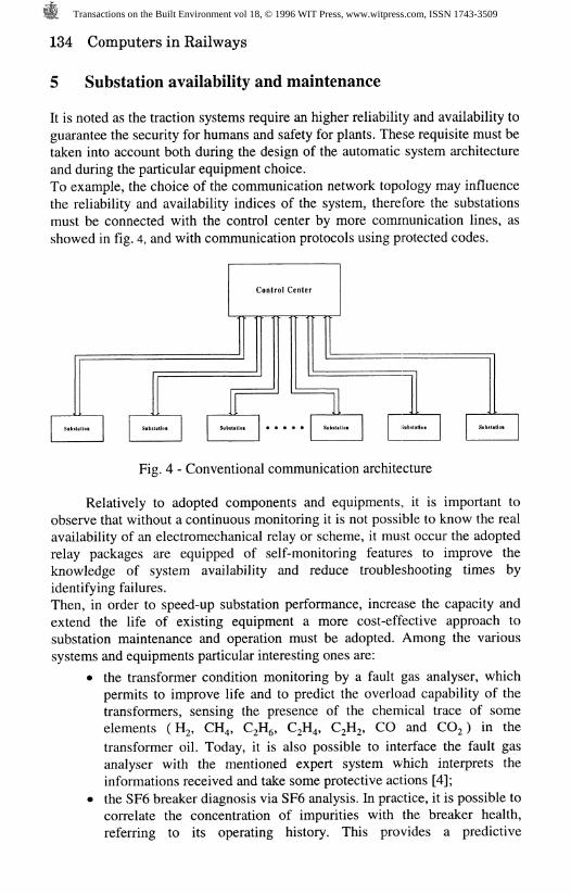
It is noted as the traction systems require an higher reliability and availability toguarantee the security for humans and safety for plants. These requisite must betaken into account both during the design of the automatic system architectureand during the particular equipment choice.To example, the choice of the communication network topology may influencethe reliability and availability indices of the system, therefore the substationsmust be connected with the control center by more communication lines, asshowed in fig. 4, and with communication protocols using protected codes.
Fig. 4 - Conventional communication architecture
Relatively to adopted components and equipments., it is important toobserve that without a continuous monitoring it is not possible to know the realavailability of an electromechanical relay or scheme, it must occur the adoptedrelay packages are equipped of self-monitoring features to improve theknowledge of system availability and reduce troubleshooting times byidentifying failures.Then, in order to speed-up substation performance, increase the capacity andextend the life of existing equipment a more cost-effective approach tosubstation maintenance and operation must be adopted. Among the varioussystems and equipments particular interesting ones are:
• the transformer condition monitoring by a fault gas analyser, whichpermits to improve life and to predict the overload capability of thetransformers, sensing the presence of the chemical trace of someelements (H%, CH,, C , C , C , CO and CO%) in the
transformer oil. Today, it is also possible to interface the fault gasanalyser with the mentioned expert system which interprets theinformations received and take some protective actions [4];
• the SF6 breaker diagnosis via SF6 analysis. In practice, it is possible tocorrelate the concentration of impurities with the breaker health,referring to its operating history. This provides a predictive
Transactions on the Built Environment vol 18, © 1996 WIT Press, www.witpress.com, ISSN 1743-3509
Computers in Railways 135
maintenance tool [4];
• the substitution of the conventional protective relay with digital ones.This new kind of relay permit to execute self diagnostic andmonitoring programs [5].
This preventive maintenance approach permits both to improve the availabilityof components, finding an anomaly of a monitored equipment before it leads toa fatal fault, and to reduce the manpower for plant maintenance, usingequipment with self-monitoring features, with obvious improvement of thequantifiable and unquantifiable economical benefit
6 Communication architectures for traction system
The adoption of automation in traction substation requires suitablecommunication architectures. This consideration comes out still clearer if someelectric conditions, typical of transportation systems, such as remote faults oroverload currents are considered.
Relatively to the remote fault detection, it must be observed that itsundoubted detection in DC electric traction plants is extremely difficult. Such adifficulty derive from the presence of long contact wires, which are alsosubjected to high overload, up to 3 times the rating power. These circumstancesproduce a strong reduction of fault current, which in such a case can be lowerthan the overload current.
A further worsening of the conditions may be represented by the presenceof an equipotential mesh, which can cause both a further reduction and a profilechange of the fault current.
Therefore, the choice of the substation feeding current, as sensingelement in fault detection, not always may guarantee the breakers change over,so in some cases it must be forced to measure quantity different from currentand to modify the traditional protective philosophies. Further informations, ingeneral relative to the plant outside the substations and in the most cases of anot electric nature are required.
Such a kind of event, moreover typical of traction systems, can be easilymodelled and managed with the automatic techniques previous exposed. Theypermit to integrate the information relative to current and voltage of thesubstation both with digital signals coming from digital relays, located in themiddle and at the end of the line, and with such informations relative to thesystem operating state as number of trains, trains running mode, trains current,etc. . So, from the knowledge of the whole system a faster fault currentdetection is possible, locking the high-speed circuit-breakers to avoid furtherelectric straining to the various equipments.
At the same way, it is possible to distinguish between a fault current andan overload one, coupling to the signals coming from the rate of change ofslope relays that one relative to the presence of trains on the track section,affected by overcurrent. It will permit to avoid the untimely high-speed circuit-
Transactions on the Built Environment vol 18, © 1996 WIT Press, www.witpress.com, ISSN 1743-3509
136 Computers in Railways
breakers trip, due to example to the speed passing of the traction load from abreaker to another, obtaining a strong reduction of the number of faults peryear.
A further advantage directly reachable is to limit, with fast interventions,the faults propagation, so it is possible to delimit the plant area affected bysevere fault conditions, making possible to continue the operation on theremaining areas.
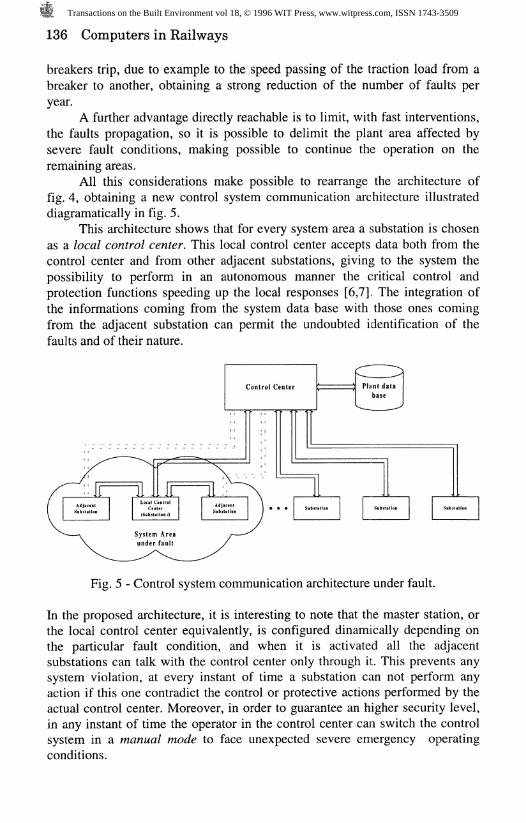
All this considerations make possible to rearrange the architecture offig. 4, obtaining a new control system communication architecture illustrateddiagramatically in fig. 5.
This architecture shows that for every system area a substation is chosenas a local control center. This local control center accepts data both from thecontrol center and from other adjacent substations, giving to the system thepossibility to perform in an autonomous manner the critical control andprotection functions speeding up the local responses [6,7]. The integration ofthe informations coming from the system data base with those ones comingfrom the adjacent substation can permit the undoubted identification of thefaults and of their nature.
Fig. 5 - Control system communication architecture under fault.
In the proposed architecture, it is interesting to note that the master station, orthe local control center equivalently, is configured dinamlcally depending onthe particular fault condition, and when it is activated all the adjacentsubstations can talk with the control center only through it. This prevents anysystem violation, at every instant of time a substation can not perform anyaction if this one contradict the control or protective actions performed by theactual control center. Moreover, in order to guarantee an higher security level,in any instant of time the operator in the control center can switch the controlsystem in a manual mode to face unexpected severe emergency operatingconditions.
Transactions on the Built Environment vol 18, © 1996 WIT Press, www.witpress.com, ISSN 1743-3509
Computers in Railways 137
7 Cost/Benefit analysis
Relatively to the main quantifiable potential economic benefit of a substationautomation system, it is possible to say that they are classifiable in two majorcategories as follows:
• reduction in capital expenditures;• reduction in operating and maintenance costs.On the other side, while the reduction in capital expenditures can be
analysed only if specific planning studies are conducted for the site in question,the reduction in operating and maintenance costs can be evaluated by usingsimply equations that compute, on the base of historical statistics, costs of thenon-automated substation which may be reduced when the correspondingsubstation automation functions are implemented. From experiences on smalltransportation system, the substation automation is justified on the basis of theoperating and maintenance savings [8].
Relatively to unquantifiable benefits it is important to point out that theintroduction of automation may improve the security of passengers andmanpower, the reliability and availability of the system, and the customerssatisfaction [8].
7 Conclusions
This paper has shown how the automation of traction substations can increasethe reliability and availability of the whole electric power system. The maincontrol and protection functions at substation level have been pointed out and apossible integrated control system architecture has been indicated. Also thecontribution of such new control techniques as artificial neural network, expertsystem and fuzzy system in the system restoration or fault management hasbeen discussed. In the latter part of the paper the possibility to demand somefunctions or applications from the control center to the substation local controlcenter is showed.All solutions described above have showed that
References
[1] Hoi, A.L. & Coomer, R.J. Micro-controller for substation and networkautomation, Proceedings oflEE Third International Conference on FutureTrends in Distribution Switchgear, London, UK, April, 1990, pp. 84-89.
[2] Blanquet, A., Penha Inacio, J., Barros Moura, P. & Seruca, J. Substationautomation and control on distribution networks, Proceedings of IEEInternational Conference on Electricity Distribution (CIRED), Brighton,UK, May, 1989, vol. 4, pp. 346-350.
[3] Pedersen, A. & Rein, P. Possible architectures of future control systemsbased on computer tecnique, Proceedings of CIGRE Symposium on
Transactions on the Built Environment vol 18, © 1996 WIT Press, www.witpress.com, ISSN 1743-3509
138 Computers in Railways
Digital Technology in Power Systems, Bournemouth, June, 1989, section1 A, paper 1A-01.
[4] Kawada, H., Hasegawa, T., Ose, K., Fukuda, T., Mukaiyama, Y.,Moriguchi, S., Noguchi, H. & Ito, N. Present situation and future plans ofoperation and maintenance supporting system at substation, Proceedingsof CIGRE Symposium on Digital Technology in Power Systems,Bournemouth, June, 1989, section 1A, paper 1A-06.
[5] Yoshiki, Y, Jinzenji, T., Kudor, T., Inokuchi, H., Fujiwara, J. & Kondo, A.Static power supply for DC 1500 V transit system, Proceedings of IEEInternational Conference on Main Line Railway Electrification, York, UK,September, 1989, pp. 164-168.
[6] Booth, C, McDonald, J.R., Stewart, R.W., Laycock, W.J. & Bennett, K.Enhanced power system control and management via intelligentsubstations, Proceedings of IEE Second International Conference onAdvances in Power System Control, Operation and Management, HongKong, December, 1993, vol. 2, pp. 542-547.
[7] Gellen, S.J. Distributed intelligence in supervisory control and dataacquisition systems, Proceedings of IEE International Conference onElectricity Distribution (CIRED), Brighton, UK, May, 1989, vol. 4, pp.327-330.
[8] Brown, D.L., Skeen, J.W., Daryani, P. 6 Rahimi, F.A. Prospects fordistribution automation at Pacific Gas & Electric Company, IEEETransaction on Power Delivery, October, 1991, vol. 6, issue 4, pp. 1946-1954.
Transactions on the Built Environment vol 18, © 1996 WIT Press, www.witpress.com, ISSN 1743-3509