Resistance to rolling in the adhesive contact of two ...
22
/_ 207225 PHILOSOPHICAL MAGAZINE A, 1995, VOL. 72, NO. 3, 783-803 Resistance to rolling in the adhesive contact of two elastic spheres By C. DOMINIK and A. G. G. M. TIELENS NASA Ames Research Center, Mail-Stop 245-3, Moffett Field, CA 94035, USA [Received 20 December 1994 and accepted 21 Februar 3, 1995] ABSTRACT For the stability of agglomerates of micron sized particles it is of considerable importance to study the effects of tangential forces on the contact of two particles. If the particles can slide or roll easily over each other, fractal structures of these agglomerates will not be stable. We use the description of contact forces by Johnson, Kendall and Roberts, along with arguments based on the atomic structure of the surfaces in contact, in order to calculate the resistance to rolling in such a contact. It is shown that the contact reacts elastically to torque forces up to a critical bending angle. Beyond that, irreversible rolling occurs. In the elastic regime, the moment opposing the attempt to roll is proportional to the bending angle and to the pull-off force Pc. Young's modulus of the involved materials has hardly any influence on the results. We show that agglomerates of sub-micron sized particles will in general be quite rigid and even long chains of particles cannot be bent easily. For very small particles, the contact will rather break than allow for rolling. We further discuss dynamic properties such as the possibility of vibrations in this degree of freedom and the typical amount of rolling during a collision of two particles. § I. INTRODUCTION The coagulation of small solid particles is a process of great importance in a wide range of fields such as material sciences (sintering) atmospheric sciences (aerosols) and also astrophysics (the formation of planets; see, for example, Weidenschilling, Donn and Meakin (1988)). Many studies of coagulation have been carried out both on the experimental side and on the theoretical side. Coagulated aggregates have structures that vary from quite compact to open fractal. Numerical simulations and also theoretical arguments (see, for example, Ball and Witten (1984)) have shown that the density of aggregates reflects the formation process, in particular the type of trajectory of the approaching particles (ballistic or random walk). A further important factor is the difference between particle-cluster aggregation and cluster-cluster aggregation. In particular, the addition of single particles to the cluster gives rise to quite compact structures as compared to cluster-cluster aggregation. However, examination of pictures of (especially low density) aggregates shows that the stability of the adhesive joints is also an important factor for the structure (Kantor and Witten 1984). Often, the aggregates consist mainly of quasi-linear chains of particles with no more than two contacts per particle. Only strong joints can survive collisions with further particles without tearing, and only if the joints can resist tangential forces will the chains continue to be linear. If, for example, rolling of one g_ainover the other were easy, the chains would quickly fold and the aggregates would become considerably more compact. 0141-86t0/95 $10.00 © 1995 Taylor & Francis Ltd
Transcript of Resistance to rolling in the adhesive contact of two ...

/_ 207225
PHILOSOPHICAL MAGAZINE A, 1995, VOL. 72, NO. 3, 783-803
Resistance to rolling in the adhesive contact
of two elastic spheres
By C. DOMINIK and A. G. G. M. TIELENS
NASA Ames Research Center, Mail-Stop 245-3, Moffett Field, CA 94035, USA
[Received 20 December 1994 and accepted 21 Februar 3, 1995]
ABSTRACT
For the stability of agglomerates of micron sized particles it is of considerable
importance to study the effects of tangential forces on the contact of two particles.If the particles can slide or roll easily over each other, fractal structures of these
agglomerates will not be stable. We use the description of contact forces by Johnson,
Kendall and Roberts, along with arguments based on the atomic structure of thesurfaces in contact, in order to calculate the resistance to rolling in such a contact.It is shown that the contact reacts elastically to torque forces up to a critical bending
angle. Beyond that, irreversible rolling occurs. In the elastic regime, the moment
opposing the attempt to roll is proportional to the bending angle and to the pull-offforce Pc. Young's modulus of the involved materials has hardly any influence on
the results. We show that agglomerates of sub-micron sized particles will in generalbe quite rigid and even long chains of particles cannot be bent easily. For very small
particles, the contact will rather break than allow for rolling. We further discuss
dynamic properties such as the possibility of vibrations in this degree of freedomand the typical amount of rolling during a collision of two particles.
§ I. INTRODUCTION
The coagulation of small solid particles is a process of great importance in a wide
range of fields such as material sciences (sintering) atmospheric sciences (aerosols) and
also astrophysics (the formation of planets; see, for example, Weidenschilling, Donn
and Meakin (1988)). Many studies of coagulation have been carried out both on the
experimental side and on the theoretical side. Coagulated aggregates have structures
that vary from quite compact to open fractal. Numerical simulations and also theoretical
arguments (see, for example, Ball and Witten (1984)) have shown that the density of
aggregates reflects the formation process, in particular the type of trajectory of the
approaching particles (ballistic or random walk). A further important factor is the
difference between particle-cluster aggregation and cluster-cluster aggregation. In
particular, the addition of single particles to the cluster gives rise to quite compact
structures as compared to cluster-cluster aggregation.
However, examination of pictures of (especially low density) aggregates shows that
the stability of the adhesive joints is also an important factor for the structure (Kantor
and Witten 1984). Often, the aggregates consist mainly of quasi-linear chains of
particles with no more than two contacts per particle. Only strong joints can survive
collisions with further particles without tearing, and only if the joints can resist
tangential forces will the chains continue to be linear. If, for example, rolling of one
g_ainover the other were easy, the chains would quickly fold and the aggregates would
become considerably more compact.
0141-86t0/95 $10.00 © 1995 Taylor & Francis Ltd

784 C. Dominik and A. G. G. M. Tielens
As far as the breaking of the aggregate is concerned, certainly the most importantparameter is the pull-off force
Pc = 3nyR, (1)
which is the force required to separate two spherical particles in an adhesive contact.
Here 2_ is the specific energy of adhesion for the two surfaces and 1/R = I/RL + 1/R2is the reduced radius of the particles involved. The factor 3 is the value obtained from
the JKRS theory (see below). For very hard spheres, this factor should rather be 4
(Muller, Yushenko and Derjaguin 1982).
When the forces involved are not sufficiently large to destroy an aggregate, it is still
possible to deform it by bending the particle chains, rolling the spheres over each other
or sliding the surfaces along each other. The latter is not likely to be too important after
the formation of the aggregate, since the forces needed to break a contact by horizontalforces are usually larger than the pull-off force (Savkoor 1992). However, what should
be much easier is bending these chains, and eventually moving the contacts by rollingthe particles over each other.
To get a handle on this, it is important to know which forces oppose the attemptto roll one body over the other in an adhesive contact. In this paper, we will developa model which invokes both the properties of an adhesive contact between two elastic
spheres and, to some extent, the molecular structure of the surfaces in order to calculate
these forces and to estimate the energy dissipated in the rolling process.
§ 2. THE JKRS SOLUTION FOR THE CONTACT PROBLEM BETWEEN TWO
ADHESIVE SPHERES
Our considerations are based to a large extent on the solution of the adhesive contact
problem which was developed by Johnson, Kendal and Roberts ( 1971) (JKR) and also
by Sperling (1964). The JKRS solution is based on fracture-like energy considerations.
The main assumption leading to this solution is that the forces between the two spheresare pure contact forces. That is, two grains feel only an attractive forces across thecontact area, while the surface areas outside the actual contact area are force-free.
Certainly, such an approximation has its limitation. It was shown by Muller, Yushenko
and Derjaguin (1979) that JKRS is more appropriate in the case of large soft spheres.
For small and very hard spheres, the description by Derjaguin, Muller and Toporov
(1975) is more accurate. We have decided to adopt JKRS for the time being, since the
assumption of contact forces considerably simplifies the discussion of rollingresistance.
JKR showed that two elastic adhesive spheres make contact over a finite circular
region, as indicated in fig. 1. In the case of no external applied forces, the radius of thiscontact area is
= (9_7R2_ 1/3ao \_-] , (2)
where 7 is the surface energy of each surface. For different surfaces, ), = 7J + )'2 - 27_2,
where 7_ is the interface energy. R is the reduced radius of the two spheres(R-1=R(I+R2 l) and (E*)-_=(I--v_)/El+(1-v_)/E2, where Ei and vi are
Young's modulus and Poisson's ratio, respectively, of grain i. The elastic displacementof the two spheres along the line connecting the centres of the two spheres (again with

Resistance to rolling 785
Fig. 1
2
_ boay 1
contact point
coordinate origin
Sketch of the geometry of the contact area between two elastic spheres. The two bodies make
contact overa circular region with radius a. Inside the contact region, the surfaces interact
by a mutual pressure p (which in adhesive contact can also be negative). When tangential
forces are applied, they are transmitted by tangential tractions q in the contact'area. The
contact area is always in the x-y plane.
zero external force) is given by
Pcg0 - (3)
E*ao '
where -Pc = -3rt?R is the maximum external force that can be applied without
breaking the contact (the so-called pull-off force). In the following we will sometimes
use dimensionless quantities, denoted by a hat over a symbol:
P ¢_z 6z a/5=p__,c =600' t_=--. (4)a0
Here P is the applied external load. When this load differs from zero, both the contact
radius and the displacement change. The following relations between load, displace-
ment and contact radius hold for the JKRS solution:
/D = 4(t_ 3 -- t_3/2), (5)
¢_= 34 2 - 2_ w2. (6)
The distribution of pressure in the contact area is given by a superposition of Hertz' s
and Boussineq's contact problems:
p(r, a) = pH(l -- r2/a 2) + pB(l -- r2/a 2) - 1/2. (7)
In JKRS, the two constants are given by
pH _- 6 P--_2d,rCao
1/2
7r_2o
(8)
(9)

786 C. Dominik and A. G. G. M. Tielens
§ 3. RESISTANCE TO ROLLING IN A JKRS CONTACT
Resistance to rolling is a force that opposes the attempt to roll a body on the surface
of another body. To measure this force we might apply a force Qx at the centre of a
sphere with radius R_ in the x direction parallel to surface on which the sphere rolls.
In order to study this effect independently of the sliding process, we assume that
sliding friction is high enough to prevent sliding entirely. Then, the tangential force Qxis balanced by an equal force in the contact area. However, since the two forces are
applied at different points on the sphere, there is a resulting torque about the y axiswhich is
Mr= QxR. (10)
In order to prevent the sphere from starting to roll, this torque has to be balanced by
an appropriate pressure distribution in the contact area. In order to produce a resultantmoment (the so-called rolling moment), the distribution would have to be asymmetric
with respect to the y axis. However, the pressure distribution in JKRS is always
cylindrically symmetric with respect to the contact point. Since this impliesp(x,y) = p(- x,y), there is no moment associated with this distribution:
My= f fxp(x,y)dxdy=O. (11)
Different mechanisms have been discussed in order to explain the observed rolling
friction at least in the adhesion-free problem. The different possibilities are micro-slipat the interface, ineleastic deformation of the involved materials and surface
irregularities; these have been summarized by Johnson (1989). However, none of thesemechanisms should be of great importance in the contact of (sub-) micron-sized
particles, of which adhesive aggregates usually consist. The displacements at the
surfaces of the particle are usually not much larger than one or a few diameters of theatoms in the solid. Therefore, the movement of dislocations, which for macroscopic
crystalline bodies is the source of inelastic behaviour, will play no role at very smallparticle sizes. Likewise, surface roughness is unimportant on the 50/_ size scale of the
contact area of sub-micron-sized particles.
However, for very small spheres, the surfaces can no longer be treated as perfectly
smooth at all scales, since they are made of atoms. Then it becomes clear that the contact
area cannot be perfectly symmetric. During rolling, new contact at the leading edge ofthe contact will not be made continuously, but rather in steps after a rolling distance
of approximately one grid constant of the material. Likewise, at the trailing edge, thecontact is lost in steps. Therefore the pressure distribution will not be exactly
symmetrical all the time.Still, if new contacts at the leading edge are made very smoothly and if the processes
at the leading and trailing edges are exactly time reversed to each other, no energy will
be dissipated and the pressure distribution will still be symmetric on average. This
means that at every instant there may be a non-vanishing torque, but this torque maychange sign and the average will still be zero. However, it is known from experiments
with the atomic force microscope (Landman, Luedtke, Burnham and Colton 1990) that
the approach of a tip to an adhesive surface and subsequent retraction involves a
hysteresis. Upon close approach, the tip will form an adhesive contact with the substrate.
Upon retraction, however, the tip will pull out a neck of surface material and contactwill not be broken until a critical displacement is reached. A similar process occurs for
a single atom attracted by van der Waals forces to the substrate and held back by

Resistance to rolling 787
sidm viav
of sp_mre
in contact
with Dlata
Fig. 2
_tric _FmMtric li,an_tric
prammtut'a dimt. Drammuz'a dist. pralm_a _mt.
,Q ,QTop View I I I I
of contact
areaI I I I
I i I I I i
Modml of t_ 2a
al_trlc
contact I I
araa i I
(a) (b) (c)
Sketch of the mechanism of rolling friction. Top: side-view on an elastic sphere in adhesivecontact with a rigid plane. Centre: top-view on the contact area. The dotted circleindicates the position of the contact point (the projection of the sphere centre). From le_to right, the diagram shows (a) an initial torque-free state with contact area centredaround the contact point, (b) a state with resulting torque where the contact area is notcentred and (c) the final and again torque-free state after the contact area has readjusted.Bottom: decomposition of the asymmetric contact area into two half-circles of differentradii.
spring-like binding forces in the approaching tip (see, for example, the discussion in
Israelachvili (1992)). Upon approach, the atom will jump into contact with the substrate.The energy difference between the two states before and after the jump is dissipated.
The same process occurs upon retraction between a different pair of states. It has been
suggested by Tom_inek (1993) that this hysteresis might be the source of atomic scale
rolling friction. In this paper, we follow up this idea and try to calculate the forcesinvolved.
A possible approach to calculate the rolling friction in an adhesive contact would
be to look directly at the energy dissipated in the making and breaking of contacts. This,
however, requires an accurate knowledge of the forces between the atoms and an
accurate description of the transition between the contact area itself and the surrounding
parts of the spheres.We therefore follow a different approach. The retarded making and breaking of
contacts means that the contact area will not always be centred around the line
connecting the centres of the two spheres, but rather will be shifted by a certain amount
to one side. This shifted contact area leads to an asymmetric pressure distribution, aswe will show below.
For now we restrict out terminology to the case of a rolling elastic sphere on a rigid
plane. However, the case of two elastic spheres can be treated by simply replacing the
sphere radius R and the elastic constant E* with reduced quantities.To describe the rolling process we visualize it as shown in fig. 2.
(1) We start from a situation where the contact is a JKRS contact centred around

788 C.DominikandA. G.G.M.Tielens
thecontact point which is the point vertically below the centre of the sphere.
With two spheres it would be the point on the line connecting the two centres.
(2) Then the sphere is rolled a small distance over the surface. If _y denotes the
angular motion, the contact point moves a distance _ = R6_y. However, we
assume that the contact area remains behind. Thus the contact area is no longer
centred around the actual contact point, but is shifted by a distance ¢. In thisstate there will be a non-vanishing torque opposing the rolling direction. In § 3.1
we will calculate this torque.
(3) At a certain critical rolling distance 4Yield(which should be typically of the order
of one atom diameter in the material) the contact area readjusts--that is, contact
is lost at the trailing edge and new contact is formed at the leading edge--so
that again a symmetrical (torque-free) distribution is formed.
In the following we will calculate the moment that is produced by the asymmetric
pressure distribution.
3.1. The moment associated with a shifted contact area
To our knowledge, there are no analytical solutions for the problem of a shifted
contact area. To calculate the pressure distribution and the associated moment we
proceed as follows:
(1) The true shifted contact area is approximated by a decomposition into two half
circles of different radii a + 4, respectively (see fig. 2).(2) The half circle x < 0 is one half of a symmetrical contact with contact radius
a + _ and pressure distributionp(r, a + _, 6z) (see below for the definition of this
pressure distribution).
(3) the half circle x > 0 has a smaller contact radius a - 4 and a corresponding
pressure distribution p(r, a - 4, 6z).(4) The total momentum due to both half circles is calculated.
The resulting distribution is discontinuous at x = 0. As indicated in fig. 2, the true
contact area is closely fitted far from the y axis where the contributions to the moment
are most important. In Appendix 1 we discuss the two-dimensional (2D) case wherethe exact pressure distribution can be obtained analytically. That analysis shows that
the above approximation gives reasonable results.
We start from the general pressure distribution for the contact of two elastic spheres
with a contact radius a. This pressure distribution is the superposition of the solutions
of the Hertz problem and of the Boussineq problem. The subscripts H and B indicatethat in the following:
pa (12)p(r, a, t_z) = pH(1 - r21a2) 1/2 q_ ( 1 - r21a2)1/2"
The pressure distribution corresponds to a normal displacement of the spheres
_a
6z = 2_(Pn + 2pa). (13)
To calculate the moments of one half of the contact area for different sizes for the
contact area we cannot directly use the JKRS equations since the different contact radii
a always correspond to different values for 6z. For the intended calculation, however,

Resistance to rolling 789
we need contact areas of different sizes but with the same normal displacement 6z. Wehave thus to start from eqn. (12).
For a contact area of a given size, the constant pH has the fixed value PH = 2aE*/rtR,
since it is this part of the solution that deforms the spherical surface to a fiat area.
Different values of 6z can be achieved by changing only the Boussineq part of the
solution. Therefore we will now replace the Boussineq constantpn with eqn. (13). Then,we may keep 6z constant and change the size of the contact area.
An expression for pa can be obtained from eqn. (13):
E*pB(a) = -- 6z -- ½PH(a). (14)
rta
We insert this into eqn. (12) and get
p(r, a, 6z) = PH( 1 -- r2/a 2) I/2 + (E*/lta)6: - pu/2 (15)(1 - r2/a2) 1/2
As discussed above, we compose the asymmetric contact region of two halves. The
distribution inside each half is taken to be that of a symmetric pressure distribution with
contact radius a + _ and a -- _, respectively:
_p(r,a+_,fz), x<O,p_(r,a,() = Lp(r,a- ¢,6_), x>0. (16)
The moment associated with this distribution is
My = xp(r,a + _, 6z)rdrd_0 + xp(r,a - 4, 6z)rdrd_o. (17)J ru'2 - n/2
With x = rcos _9 we may carry out the _0 integration and find
fl _+_ f¢-_My = - 2 r2p(r, a + 4, 6z) dr + 2 r2p(r, a - 4, 6z) dr (18)
= _ /IAr(I/2) _£_ i,4"(I/2),,,y,_+ _ .... y.___. (19)
Thus we have to solve integrals of the kind
_v_'i(l_)y,._,o_"= 2 (r, d, _z) dr. (20)
The required integrals are given by eqns. (87) and (88) in Appendix B. The result is
E*'",._'._A'r('/2)=2[PHl_C3+(_z_½Pn)¼_3 ] (21)
= ½E*d23z - _ pHd 3. (22)
We insert the correct value of PH (eqn. (8)):
M(U2) E* 2 "sJ4_,_._ = T6_ - _e_ _. (23)
The moment of the whole asymmetric contact can now be calculated from eqn. (19).We keep 6z constant and neglect all terms of higher than first order in 4/a. This is
equivalent to the substitutions d_ ¢4 _ -- 8a3_ and _2 ___ _ 4a_:

790 C.DominikandA.G.G.M.Tielens
My _ 2_( - E*a6z + 3pc_3). (24)
Now we may insert the correct value fiz which is the value from Johnson's solution
corresponding to a contact area radius a as given in eqn. (6). The result is
My = 4Pc_3a_. (25)
The moment associated with a contact area shifted by a distance _ is therefore
proportional to the pull-off force and to the shift itself. The order of magnitude of thisresult is what one would have expected, since the forces involved are of the order of
Pc and the force is applied over a level of length ¢. The dependence on the normal load
P enters through the factor din, which should be close to one in most cases (see below).
In the following section we will discuss in greater detail the properties of the rolling
moment and its implications on the structure and stability of agglomerates.
§ 4. MECHANICAL PROPERTIES OF THE CONTACT UNDER THE INFLUENCE OF ROLLING
MOMENTS
4.1. Static considerations
Equation (25) shows that the force opposing the attempt to roll one particle overthe other is a torque that is proportional to the angular displacement. However, as the
displacement increases there is a limit to the increase in that force. When the line
connecting the two particle centres has moved a certain critical distance over thesurfaces, the contact area will start to move, and the force will decrease or drop to zero.
We will call this critical distance the yield displacement _yield = Rt_yaield. _yield should beof the order of the distance between atoms in the materials, typically 2 ,_. Therefore,
the adhesive contact reacts elastically in a small displacement interval. For larger
displacements, energy is dissipated and the contact area moves irreversibly over thesurfaces.
Due to the simple structure of eqn. (25), the calculation of several mechanical
properties is quite straightforward. We will illustrate the results in some figures, whichshow the involved forces and other quantities as functions of the surface energy ), and
of the particle radius R (see figs. 3 and 6).For the following discussion we will restrict ourselves to the contact between
identical spheres with radius RI. Then, R = RI/2 and Pc = _r_TR_. Furthermore, we
neglect the variations in the rolling moment due to variations in the normal force. Theseenter into eqn. (25) in the factor 63r2. However, if the normal force stays within the range
- Pc < P < Pc, the factor t_15 varies only in the range between 0.5-1.2. Larger normal
forces are likely to eventually destroy the contact, and are therefore not relevant to our
problem. Therefore, we assume for most of the rest of the paper that ,_ = 1.
Since we have neglected the normal load, the surface energy 7 is the sole material
property that enters into the equations. In the diagrams, we will therefore usually plot
on the abscissa. Every material or combination of materials may then be associated
with a position on this axis. We have plotted the positions of some materials on the topof the diagrams. The material properties used are summarized in the table. The ordinate
of the plots is labelled by the reduced particle radius. Therefore, for a given system,
the results can be read immediately from the figures.
The first quantity of interest is the tangential force that can be applied at the centre
of the particles in order to exceed the yield displacement. In other words, to which
limiting force does the contact still react elastically? A force Qyield applied at the particlecentres, corresponds to an applied moment at the contact point of M yield ---- QyieldRl, thus
Resistance to rolling 791
-4
0
Fig. 3
-2- ''-L ' (c) '' ' ' '4
-4 -
iog(R.,.)=-2
o -4
-8 __ -6
(b) - (d)-6
-5 -- 1
log(q_,_./P.)= -a _ _
-2
-8 _- -1
/
.... /_ t, , I .... I ........ 1,
0 1 2 3 0 1 2 3
log 7 [mJ m -el log 7 [mJ m -el
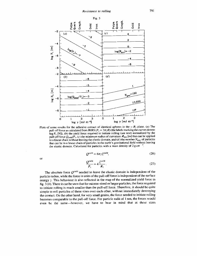
Plots of some results for the adhesive contact of identical spheres in the 7-R_ plane. (a) Thepull-off force as calculated from JKRS (Pc = 3_xTR) (the labels marking the curves denote
logPc [N]), (b) the yield force required to initiate rolling (see text) normalized by the
pull-off force Qyieid/Pc, (c) the minimum radius of curvature ._,ni, [m] that can be applied
to a linear chain without leaving the elastic domain, and (d) the number Ngra_ of particlesthat can be in a linear chain of particles in the earth's gravitational field without leaving
the elastic domain. Calculated for particles with a mass density of 2 gcm - 3.
or
Qyield = 6rtT_yi_]d ' (26)
Qyield _yield
= 4 . (27)Pc Rt
The absolute force aYield needed to leave the elastic domain is independent of the
particle radius, while the force in units of the pull-off force is independent of the surface
energy 7. This behaviour is also reflected in the map of the normalized yield force in
fig. 3 (b). There it can be seen that for micron-sized or larger particles, the force required
to initiate rolling is much smaller than the pull-off force. Therefore, it should be quite
simple to roll particles of these sizes over each other, without immediately destroying
the contact. On the other hand, for very small grains, the force needed to initiate rolling
becomes comparable to the pull-off force. For particle radii of 1 nm, the forces would
even be the same--however, we have to bear in mind that at these sizes

792 C.DominikandA. G.G.M.Tielens
Materialproperties.
Material y_" (mJ m - 2) E (N m - 2) v p (g cm - 3) Reference
Polystyrene 12 3.4 (9) 0-5 1-04 [2, 3]Quartz 25$ 5.4 (10) 0.17 2-6 [ 1,2]
Graphite 75 1.0 (I 0) 0-32 2-2 [4, 5]
Gold 790§ -- -- 19-3 [7]
Iron 3000 2-1 ( 11 ) 0-27 7-7 [2, 6]
t Surface energy per surface.
_tMeasured for micron-sized particles.
§ Mean value of the range given in the reference.
References; [1] Kendall, Alford and Birchall 1987, [2] Anderson 1981, [3] Kendall and
Padget 1987, [4] Brocklehurst 1977, [5] Zisman 1963, [6] Easterling and Th61en 1972,[7] Hodgman 1949.
the theory of elasticity is no longer applicable. The fact that both forces are comparable
implies that any attempt to compress an aggregate by rolling the particles over each
other would be likely to destroy the aggregate.
Another interesting quantity is the flexibility of particle chains. Many open
aggregates mainly consist of quite linear chains in a tree-like structure. A way to treat
this problem is to calculate the minimal radius of curvature that a linear chain of particles
can adopt, again without leaving the elastic domain. If we bend every contact to its limit
(which is the angle _yield = 2_yield/gl), the radius of curvature of the chain is
_rnin _yield ' (28)
a result that is mapped in fig. 3 (c). The minimal radius of curvature is generally large
compared to the radius of the particles. Even for rather small spheres (100nm), the
minimal radius of curvature is about 50 _tm, thus a factor of 500 times larger. This means
that a chain would have to be a few thousand grains long in order to be elastically bent
to a circle. Chains shorter than this length would appear as quite rigid structures that
could not be reversibly bent. Because of this rigidity, fractal 'fingers' of aggregates do
not close up into ring-like structures easily.
In a laboratory, the aggregate is usually subjected to the earth's gravity. Another
interesting question is, therefore, whether an aggregate will collapse under its own
weight and flatten. We will restrict ourselves to a very simple consideration. We again
look at a linear chain of N particles bonded by adhesion and fixed at one end to the wall
(c.f. fig. 4). We make the further simplification that the chain is not bent, but assume
Fig. 4
mtj _ mg a_ mg mg a_
Experiment for the determination of the influence of the earth's gravitational field on the stabilityof an aggregate.

Resistance to rolling 793
that it is a straight line. This is certainly justified by the above discussion of the radiusof curvature. We may then compute the torque that acts on the key contact of the chain
(which is the strongest torque anywhere in the chain). It is given by
M_aV(N) = mgRIN 2, (29)
where m is the mass of an individual particle, g is the gravitational acceleration and N
is the number of grains in the chain. Irreversible rolling occurs now when N > Ng ....where
(97_Yie,a, ,nNgr.v= ' (30)
and p is the specific density of the grain material. We have calculated Ngrav for
p = 2g cm - 3 and plotted this in fig. 3. The results hardly depend on the density, since
Ngr_ scales only with the square root of p. It is obvious that for particles larger than
about 100 lain, even a gingle particle is heavy enough to start rolling under the earth's
gravity. However, with decreasing particle size, the number of grains that can be
supported increases rapidly. A chain of approximately one thousand 100 nm spheresis still stable under the earth's gravity. A more careful analysis of the stability of tenuous
structures (not limited to straight chains of particles) was carried out by Kantor and
Witten (1984), using a parametrized strength of the contact. The size limits established
in their study are in good agreement with our results when appropriate estimates for
the contact strength are used.
4.2. Dynamic considerations
4.2.1. Vibrations
As already noted above, for small angular displacements the moment produced by
the displacement is proportional to the displacement itself. It should therefore be
possible to excite vibrations where two particles in contact oscillate around the
equilibrium state as shown in fig. 5 (b). Before we calculate the frequency associated
Fig. 5
(a) (b)
The two modes of vibration considered in § 5.2.1. (a) Vertical vibration: the vertical displacement3z is oscillating, when the distance between the sphere centres increases and decreases;(b) rolling vibration: the angular displacement 6ay oscillates, when the spheres roll backand forth over each other.
794 C.DominikandA. G.G.M.Tielens
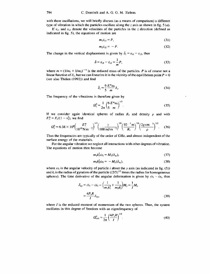
withtheseoscillations,wewill brieflydiscuss(asameansof comparison)adifferenttypeofvibrationinwhichtheparticlesoscillatealongthez axis as shown in fig. 5 (a).
If vz, and vz2 denote the velocities of the particles in the z direction (defined as
indicated in fig. 5), the equations of motion are
m,r)z, = P, (31)
m2f;z2 = - P. (32)
The change in the vertical displacement is given by 6z = Vz, - re2, thus
1= t_zl - _z2 =--P, (33)
m
where m = (1/m, + l/m2)- 1 is the reduced mass of the particles. P is of course not a
linear function ofaz, but we can linearize it in the vicinity of the equilibrium point P = 0(see also Th61en (1992)) and find
_z _ 6 E*ao 8z. (34)5 m
The frequency of the vibrations is therefore given by
0 1(6 )o ,3,,If we consider again identical spheres of radius Rt and density p and withE* = El1(1 - v_), we find
[" E* ]["/3" ],/6/10-7m]T/6(2gcm 3],/2Q°_6.38 × (36)10s l0 1 2
Thus the frequencies are typically of the order of GHz, and almost independent of the
surface energy of the materials.
For the angular vibration we neglect all interactions with other degrees of vibration.The equations of motion then become
mlk_lO)l = My(_y), (37)
m2_692 = - My( 6_,y), (38)
where o)i is the angular velocity of particle i about the y axis (as indicated in fig. (5))
and ki is the radius of gyration of the particle ((2/5) _r2times the radius for homogeneous
spheres). The time derivative of the angular deformation is given by e), - c0z, thus
_ar = (hi -- (D2 = + My = _ My
4P_R 6- I "Y' (39)
where I is the reduced moment of momentum of the two spheres. Thus, the system
oscillates in this degree of freedom with an eigenfrequency of
0 1 (4PER) '/z_¢-_roll = _ -- • (40)

Resistance to rolling 795
-4
o
-8
i i i
0
Fig. 6
4
6 j
8
, I
10
a. ot _ r_.,a.
jJ
10
1 2 3 0 1 2 3
log 7 [mJ m -2] log 7 [mJ m -e]
(a) (b)
Eigenfrequencies for the z vibration (a) and the rolling vibration (b) for two identical spheres
in contact, plotted as contour lines in a radius-surface tension diagram. The density ofthe materials was assumed to be p = 2 g cm - 3. In (a) the quantity E_ (see text) was set
to 10]°Nm -2. The curves are labelled by log (frequency) in units of Hz.
Considering two identical homogeneous spheres with radii R_ and a mass density,
p, we have
R = Rl/2, kl = k2 = (2/5)l_R1, ml = m2 = (4/3)nR_p,
0_3/ _, '_'_
OroU- _ \5R-_p] (41)
7 _ 1ez 10_Tm 3tz 2gcm-3)_tz_4'77×10(100mJm-2) (---_---i) ( p (42)
These frequencies as functions of 7 and R1 are shown in fig. 6. The eigenfrequency
associated with the rolling motion is usually one to two orders of magnitude smaller
than the frequency of the vertical vibration.
4.2.2. Energy dissipation during rolling
The rolling vibration can only take place if the amplitude is small enough. For
amplitudes larger than a critical angle ,siYield= _yieldt'e, the spheres start rolling_ty
irreversibly over each other. When we assume that after a rolling distance _y_ld the
contact area readjusts to a symmetric contact with zero torque, the average torque is
(owing to the linear dependence between torque and _)
(My) _ 2ec_ yield, (43)
which is equivalent to an average decelerating force applied at the centre of the rolling
sphere of
_yield
(Q.} _ 2P¢-- (44)R

796 C. Dominik and A. G. G. M. Tielens
Fig. 7
%Experiment to show the amount of energy lost due to rolling friction. One of the two spheres
is fixed in an inertial system (hatched area). The other sphere is approaching with a kineticenergy W0. Upon contact, the energy W0 is distributed between rotation and linearmovement. The moving sphere rolls over the fixed sphere until all energy is dissipated.
In order to visualize this energy loss we will calculate the number of full rotations
a sphere can roll with a given energy at the start. We consider a sphere colliding with
a fixed sphere (see fig. 7). We assume that sliding friction is strong enough to entirely
prevent sliding, so that the surfaces do not move relative to each other. Therefore, theinitial energy W0 is distributed into rolling and linear motion:
W0 = ½ml/) 2 "t- ½11(.D12. (45)
Since no sliding occurs, v l = m lR_. If we further observe that for a homogeneous sphere__2 2
I- 3m_R_, we find that the rotation of the sphere just after contact is
(4wq''2m(t = 0) = \7_-1/ " (46)
From then on the equation of motion m_ is given by
Mye)l -- Ii ' (47)
where My is given by eqn. (43). Integrating eqn. (47) we can find the time when the
rotation of the sphere stops, and calculate the number of rotations performed. Theresult is
1 w0nron- 14_ Pc_ yield" (48)
Thus, the number of rotations is proportional to the initial energy and inversely
proportional to the pull-off force. This seems to indicate that rolling is much more likelyin collisions between grains with a small pull-off force. However, it is also to be
recognized that grains with a small pull-off force will only stick at small impactenergies. We should therefore measure the energy W0 in units of an energy typical for
adhesion. Such an energy is given by Pc60. It has been shown by Chokshi, Tielens and
Hollenbach (1993) that this energy is of the order of the maximum energy that can be
dissipated in a slow collinear collision between two spheres, so that they will sticktogether. Then, eqn. (48) becomes
nrou- 14(9r01/3 \_] _ p_ . (49)
Thus the material properties enter only in the form of the ratio E*I7 and we may
plot n_o_lin a map as shown in fig. 8. Even in a collision with relatively large energies

Resistance to rolling 797
Fig. 8
-2
-4 -
0.1
-8
9 10 1 l 12 13
logZ'/_[m -1]
PlotofthenumberofrotationsamobilesphererollsoverafixedspherewithaninitialtangentialkineticenergyPcro.The curvesarelabelledbynroH/(Wo/P¢_o).Intheregiontothelowerright,theroilingdistanceissmallerthan_yicld.
(W0 _ P¢60), spheres with a large ratio E*/7 do not roll at all, if they are smaller than
about 10nm. Larger radii, smaller elastic moduli, or larger surface energies arefavourable to more rotation--however, the rotation is usually less than one complete
rotation if the radius of the spheres stays below 100 nm. For bigger spheres, it becomesquite possible that rolling persists for a full rotation or more. This means that in a
collision, the contact would not remain at the point of first contact. Rather, the spheres
will roll over each other. If the fixed sphere is part of an aggregate, the mobile sphere
will probably roll until at least a second point of contact is established. Therefore, the
resulting aggregates will be considerably more compact.
§ 5. CONCLUSIONS
In this paper we have discussed the resistance of a JKRS contact to rolling. This
was done by recognizing that, due to the atomic structure of the surfaces on contact,
the contact area will not be symmetric around the contact point. This asymmetric contact
area leads to a net torque force opposing the attempt to roll one body over the other.We have calculated the torque of the asymmetric contact area by an approximation in
which the area was divided into two half cycles of different size. This approximation
was justified by an exact solution for the two-dimensional case. However, it would be
very interesting to see an exact analytical solution for the three-dimensional case.
Since the maximum asymmetry of the contact area is given by the typical length
in the atomic grids of the bodies irreversible rolling starts only when the bodies roll atleast this critical distance. For smaller distances, the contact reacts elastically with a
force proportional to the displacement and to the pull-off force. As long as the contact
is not subjected to normal forces, the resistance to rolling is dependent on the surface
energy alone. Normal forces introduce a very weak dependence upon Young" s modulus.
We have also discussed some implications of our results, many of which should be
testable by experiments. The results indicate a critical bending angle below which the

798 C.DominikandA.G.G.M.Tielens
bendingwill beelastic.Thecriticalangleisquitesmall,sothatlonglinearchainsof
particles would appear rather rigid. We also showed that in the case of very small
particles the force needed to bend a chain can be comparable with the pull-off force.
Therefore, aggregates of very small grains would be very stiff. Forces applied to these
aggregates are likely to break them instead of deforming them considerably.
Finally we have shown that it should in principle be possible to excite vibrationsnot only in the vertical degree of freedom, but also in the rolling degree of freedom.
This should be visible in vibrations of fractal aggregates as well.
ACKNOWLEDGMENTS
One of the authors (C.D.) was supported during this work by the National Research
Council. Theoretical studies of interstellar dust at NASA Ames is supported under task
399-20-01-30 through NASA's Theory Program.
APPENDIX A
COMPARISON OF EXACT AND SIMPLIFIED CALCULATION OF THE ROLLING MOMENT OF AN
ASYMMETRIC ADHESION PROFILE
In this appendix we will calculate the pressure distribution and the associated rolling
moments of an elastic cylinder in contact with a rigid plane. In this 2D case, it is possible
to calculate the pressure distribution in an asymmetric contact analytically. This will
enable us to compare the rolling moment obtained from a simplifying assumption asused in § 4.1 with an exact solution.
Although we here describe only a contact between an elastic cylinder and a rigid
plane, the results can be immediately generalized to the case of two elastic alignedcylinders by just replacing the cylinder radius R and the elastic constant E* -- E/(1 - v2)with reduced values. As usual, E is the elastic modulus of the material and v is thePoisson's ratio.
Both the symmetric and the asymmetric contact are shown in fig. 9. Our treatment
of this 2D contact problem follows the description by Johnson (1989).
A. 1. The symmetric pressure distribution
When the cylinder is in contact with the plane, the deformation uz of the surface
of the cylinder is given by
X 2
uz(x)=fz 2R' -a<--x<--a (50)
Fig. 9
I t n o
i I I I
, ----_ _ ,,._--,I t
2a
Symmetric and asymmetric contact of a cylinder with a rigid plane.

Resistance to rolling 799
where we put the origin of the coordinate to the same x coordinate as the centre of the
cylinder. In the case of specified deformation in the loaded region, the pressuredistribution p(x, a) can be calculated from the following integral equation (see, for
example, Johnson (1989)):
a p(s,a) nE OUzds = . (51)j__ x-s 2 ax
This is an integral equation of the type
a p(s,a) ds = (52)g(x).-a X--S
The general solution of this equation can be obtained by applying the finite Hilberttransformation which leads to
p(x, a) = rt2(a 2 - x2) 1/2 x - s
where C is some constant of integration. In the following we add a subscript s to the
pressure distribution in order to indicate that this is the symmetric case. The application
of eqn. (53) to eqn. (51) yields
• - ds , (54)ps(x, a) = rt2(a2 _ x2)1/2 C1 + _ _ 2R x - s
E { 1 fa (a2-s2) 'n ]2R(aZ--xz)l/2 C2 +-_ -_s x-s ds . (55)
The integrand is singular at x = s and we have to take the Cauchy principal value, which
is given in eqn. (81). Inserting this result and rearranging yields
ps(x, a) = _ (a 2 -- x2) 1/2 + (C -- a2/2) (a 2 -x2)l n • (56)
The first part of the pressure distribution is the usual Hertz solution for two cylinders
pressed into contact. In this part of the solution the pressure falls to zero as x goes toa. The second part which is proportional to 1/(a2-x2) 1/2 is the one-dimensional
equivalent to the solution of Boussineq's problem which shifts the contact area
vertically by a certain amount and forms the neck which is typical for adhesive contacts.The total force per unit length P is:
foP = pdx, a) dx (57)--a
E (a 2_x2)t n+ C-a212- 2R _ ,, (a 2 _ x2)j n dx. (58)
With the integrals given in eqns. (84) and (83) this becomes
_EP = _ C. (59)
The rolling moment M,. = fxp_(x, a)dx of this pressure distribution is of course zero.

800 C.DominikandA.G.G.M.Tielens
A.2. The asymmetric pressure distribution
We now consider a contact where the contact region is of the same size as in the
symmetric case, but is shifted with respect to the centre of the cylinder by an amount
4 (see fig. 9). Then, the deformation again follows eqn. (50) but the contact strip is ashifted interval:
x2Uz(X)=fz 2R' -a-4<--x<-a-4. (60)
For the calculation of the pressure distribution it is convenient to have the contact
area symmetric about the origin. In order to do so we introduce the variable
X=x+ _. (61)
Then the deformation can be written as
(x- 4)2uz(X)=Sz 2R ' -a<--X<--a, (62)
Introducing this result into eqn. (51) yields for the asymmetric pressure distributionpa(X, a)
E [ 4_Lfa s(a_2___s2)l/2 _fa (a2s2)1/2 ]pa(X, a) = 2R(a 2 X2)1/2 C- _ )__ X - s ds - - _---_ dsJ. (63)
With eqns. (81) and (82) this can be written as
1o,= [,a2x2),2+(c a +2 x2),,2] (64)
Thus the pressure distribution differs from the symmetric one only by an additional term
which is proportional to X and, therefore, not symmetric. As we will see, this term is
responsible for the moment associated with this pressure distribution.
The total force associated with this distribution is again (see eqn. (57))
1rEP = -- C (65)
2R
and the rolling moment about the y axis which intersects the x axis at X = 0 isgiven by
aMXy=o = Xpa(X, a) dX (66)
--a
E f_a4 X 22R (a 2 _ X2)I n dX (67)
rca2 E
- _- 4. (68)

Resistance to rolling 801
We still have to transform this result back in the original coordinate system. The moment
about the y axis that intersects the x axis at x -- 0 can be calculated by
MX=_ = x=oy My -- _P, (69)
and thus
M_,_o rt E 2_ _(a + 2C). (70)4
This is the exact result which we will compare with the approximate calculation
performed in the following section.
A.3. Simplified calculation of the rolling momentThe moment of the asymmetric distribution can also be approximately calculated
in the following way. We assume that the x < 0 half of the contact area has a pressure
distribution equal to the symmetric distributionpdx, a + ¢) with contact strip half-width
a + _, while the x > 0 part of the contact area has a distribution equal to a symmetric
distribution pdx, a - _), thus with respect to a contact half-width of a - _. The overall
distribution calculated in this way is therefore not continuous at x = 0.The moment associated with this distribution is
f0 fMy = xp_(x,a + _)dx + xpdx, a - _)dx (71)a _ 1
+ fl-= - xp_(x, a + _) dx + xps(x, a - _) dx (72)
(1/2) (1/2)
=-My.,,+¢+M,,_ _. (73)
Thus we have to solve integrals of the kind
11/2, fti_Jxp_(x,_/)dxMy,._e = (74)
The required integrals are given in eqns. (85) and (86). The result is
aA,I/2) E ( _q-/3)=__'" ,..u 2R 6 + C_¢1 . (76)
The total moment is now
M, = - .,_/(1/2) ]ldt(I/2)...,,.. + ¢ + ¢, (77)
which, to first order in E/a, is
1E 2My _ _ R _(a - 2C). (78)
Comparing this result to eqn. (70), we can see that eqn. (78) is smaller by a factor
rt/2, but otherwise reproduces correctly the dependencies upon the properties of the
cylinder and upon the displacement _. This seems to be a very satisfactory result. It
justifies the use of the approximate calculation of the rolling moment.

802 C.DominikandA.G.G.M.Tielens
APPENDIX BINTEGRALS USED
The following integrals have been used in the paper. We write them in terms of twoabbreviations:
Wl(r, a) = (a 2 -- X2) 1_, (79)
W2(r, a) = ( 1 - r2/a2) lr2. (80)
B.1. Cauchy principal values of some singular integrals important in the
two-dimensional problem
P.V. f_ s(a2 - s2)t/2 ds = n(x 2 - ½a2),-a X--S
a (a 2_s2)u2P.V. ds = _x.a X--S
(81)
(82)
B.2. Non-singular integrals
a 1 dx 7z, (83)-- =
-_ Wl(r,a)
a Wl(r,a)dx = ½_xa2, (84)-a
orXWl(r, a) dx = _a 3, (85)
Wl(r,a) dx = a, (86)
" _ 7_ 3rZW2(r,a)dr - _a , (87)
fl j r2aidr r_ 3W2(r, = _ a. (88)
REFERENCES
ANDERSON, H. L. (editor), 1981, Physics Vademecum (New York: ALP).BALL, R. C., and WITTEN, T. A., 1984, Phys. Rev. A, 29, 2966.BROCKLEHURST,J. E., 1977, Phys. Chem. Carbon, 13, 145.CHOKSH1,A., TIELENS,A. G. G. M., and HOLLENBACH,D., 1993, Astrophys. J., 407, 806.DERJAGUIN, B. V., MULLER, W. M., and TOPOROV, Y. P., 1975, J. CoIL lnterf Sci., 53, 413.EASTERLING, K. E., and THOLEN, A. R., 1972, Acta metall., 20, 1001.HODGMAN, C. D. (editor), 1949, Handbook of Chemistry and Physics, 31 st edition (Cleveland,
OH: Chemical Rubber, Publishing Co.).ISRAELACHVIU,J., 1992, Intermolecular and Surface Forces (London, San Diego: Academic).JOHNSON,K. L., 1989, Contact Mechanics (Cambridge, New York: Cambridge University Press).JOHNSON, K. L., KENDALL, K., and ROBERTS, A. D., 1971, Proc. R. Soc. Lond., 324, 301.KANTOR, Y., and WITrEN, T. A., 1984, J. Physique Lett., 45, L675.KENDALL, K., ALFORD, N. M., and BIRCHALL, J. D., 1987, Nature, 325, 794.
KENDALL, K., and PADGET, J. C., 1987, J. Adhesion, 22, 39.

Resistance to rolling 803
LANDMAN, U., LUEDTKE, W. D., BURNHAM, N. A., and COLTON, R. J., 1990, Science, 248, 454.
MULLER, V. M., YUSHENKO, V. S., and DERJAGUIN, B. V., 1979, J. Coll. lnte_ Sci.., 77, 91 ; 1982,
Ibid., 92, 92.
SAVKOOR, A. R., 1992, Fundamentals of Friction: Macroscopic and Microscopic Processes,
edited by I. L. Singer and H. M. Pollock (Dordrecht, Boston, London: Kluwer), p. l I 1.SPERLING, G., 1964, PhD Thesis, Technische Hochschule Karlsruhe, Karlsruhe.
THOLI_N, A. R., 1992, Fundamentals of Friction; Macroscopic and Microscopic Processes,
edited by I. L. Singer and H. M. Pollock (Dordrecht, Boston, London: Kluwer), p. 95.TOMANEK, D., 1993, Scanning Tunnelling Microscopy IIl, edited by R. Wiesendanger and
H.-J. Giintherodt (Berlin, Heidelberg, New York: Springer), chap. I l, p. 269.
WEIDENSCHILLING, S. J., DONN, B., and MEAKIN, P., 1988, The Formation and Evolution of
Planetary Systems, edited by H. A. Weaver and L. Danly (Cambridge, New York,
Melbourne, Sydney: Cambridge University Press).ZISMAN, W. A., 1963, Ind. Engng. Chem., 55, 19.