reSilient wedge gAte vAlvedmvalve.com/.../RWGV1-14-66-Sales-Brochure-10-10-11... · 14” -66”...
20
AMERICAN FLOW CONTROL 14”-66” SERIES 2500 RESILIENT WEDGE GATE VALVE FLOW CONTROL
Transcript of reSilient wedge gAte vAlvedmvalve.com/.../RWGV1-14-66-Sales-Brochure-10-10-11... · 14” -66”...
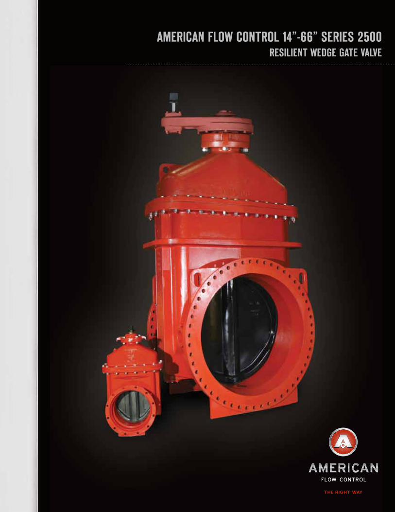
AmericAn Flow control 14”-66” SerieS 2500reSilient wedge gAte vAlve
F LOW CONTROL

Ductile ironconstructionGreater strength, durability, and lighter weight than gray iron construction. 250 psig rating.
smooth oversizeWaterWay
Helps reduce pumping costs
Ductile iron WeDGe is Fully encaPsulateD
With ePDm ruBBerHelps ensure zero leakage
with low stem torques.
cast FlatsAllow the valve to stand upright during storage or installation.
Bevel Gear - sPur GearFor horizontal installation in buried service use Bevel Gear. Use Spur Gear for vertical installation.
ePoxy coatinGinsiDe anD outHelps ensure corrosion resistance for longer service life.
stainless steelnuts anD Bolts Helps provide additional corrosion resistance.
liFtinG Devices 14”- 66”Valve is constructed of
high-strength ductile iron with integral lifting devices. This allows the valve to be
handled without having to lift the valve by the operating
nut, which could cause damage to the valve stem.
Ductile iron oPeratinG nut
Provides strength and durability.
1 2
conStruction

FeAtureS
beneFitS
SpeciFicAtionS
aDvantaGes over DouBle Disc Gate valves• Zero allowable leakage• Lower torque requirements to operate valve• Rated at 250 psig compared to the 150 psig found on most double disc gate valves• Epoxy coated inside and out• Lighter total valve weight• Single gate construction. versus multiple parts that can seize together• No need for by-passes• No need for horizontal rollers, tracks and scrapers
aDvantaGes over ButterFly valves• No disc in waterway to restrict flow or to increase pumping costs• Allows passage of pigging devices• Internal parts can be serviced without cutting valve out of pipeline.• Rated at 250 psig compared to the 150 psig found on most butterfly valves• Pumping costs are on average 1/10 that of butterfly valves.
Valves 14” - 66” shall be resilient wedge type rated for 250 psig cold water working pressure. All cast ferrous components shall be ductile iron, ASTM A536. Valves 14” - 66” shall meet or exceed all applicable requirements of AWWA C515. The words “Ductile Iron” or “D.I.” shall be cast on the valve. The wedge shall be constructed of ductile iron and be fully encapsulated with EPDM rubber. The wedge shall incorporate the use of a polymer encapsulated guide to achieve proper allignment. Wedges employing multiple guides on each side of the wedge are not acceptable.
The wedge shall be symmetrical and seal equally well with flow in either direction. The wedge nut shall be independent of the wedge and held in place on three sides by the wedge to help prevent possible misalignment. Valves shall be NSF Standard 61 Certified.
Body bolting material shall be 304 stainless steel unless otherwise specified. Bolts may have either regular square or hexagonal shaped heads with dimensions conforming to ANSI B18.2.1. Metric size socket head cap screws are not allowed. The operating nut shall be constructed of ductile iron. All gaskets shall be pressure energized O-Ring type seals. Stem shall be sealed by three O-Rings. The top two O-Rings shall be replaceable with the valve fully open and while subject to full rated working pressure. O-Rings set in a cartridge shall not be allowed. The valve shall have thrust washers located with (1) above and (1) below the thrust collar to assist operation of the valve. All internal and external surfaces of the valve body and bonnet shall have an epoxy coating, complying with ANSI/AWWA C550. Valves shall be AMERICAN Flow Control’s series 2500 resilient Wedge Gate valve.
Di constructionProvides added strength and durability
250 PsiG ratinGStandard pressure rating for all sizes
triPle o-rinG sealsHelp isolate the lubrication chamber
smooth over-size WaterWayReduces pumping costs
ePoxy coatinG insiDe anD outCastings coated prior to assembly for corrosion resistance
stainless steel BoDy BoltsProvide additional corrosion resistance
liFtinG DevicesIntegral lifting devices aid in installation Fully encaPsulateD ePDm WeDGeProvides zero leakage at 250 psig
Polymer encaPsulateD WeDGe GuiDesProtect wedge and epoxy coating during operation
o-rinG style stuFFinG Box anD throat GasketsHelps reduce excessive bolt load common in flat gaskets
Flex-rinG Joints availaBleProvides positive restrained joint without bolts
inteGrally cast FlatsValve can stand upright during storage and installation.
availaBle With american Flex-rinG JointsProvides positive joint restrant without bolts
1 2
FeAtureS/beneFitS/SpeciFicAtionS
14” -66” SerieS 2500 reSilient wedge gAte vAlve
ref Description material
1 Hex head bolt 304 Stainless steel
2 Wrench nut Ductile iron ASTM A536
3 O-Ring Rubber
4 Upper thrust washer Delrin
5 Stuffing box gasket Rubber O-Ring
6 O-Ring Rubber
7 Stuffing box Ductile iron ASTM A536
8 Bonnet Ductile iron ASTM A536
9 Hex head bolt 304 Stainless steel
10 Throat flange gasket Rubber
11 Valve body Ductile iron ASTM A536
12 Stem Bronze
13 Wedge nut Bronze
14 Resilient wedge Ductile Iron with EPDM rubber
15 Wedge cover Acetal polymer
16 Wedge cover pin Acetal polymer
17 Hex head bolt 304 Stainless steel
18 Hex nut 304 Stainless steel
19 Hex nut 304 Stainless steel
20 Pipe plug Stainless steel
21 Lower thrust washer Delrin
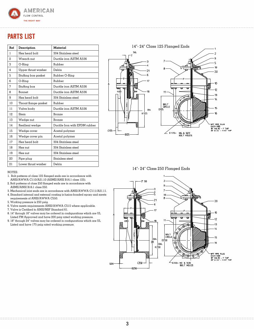
NOTES:1. Bolt patterns of class 125 flanged ends are in accordance with ANSI/AWWA C110/A21.10 (ASME/ANSI B16.1 class 125).2. Bolt patterns of class 250 flanged ends are in accordance with ASME/ANSI B16.1 class 250.3. Mechanical joint ends are in accordance with ANSI/AWWA C111/A21.11.4. Standard internal and external coating is fusion-bonded epoxy and meets requirements of ANSI/AWWA C550.5. Working pressure is 250 psig.6. Valve meets requirements ANSI/AWWA C515 where applicable.7. Valve is Certified to ANSI/NSF Standard 61.8. 14” through 16” valves may be ordered in configurations which are UL Listed FM Approved and have 200 psig rated working pressure.9. 18” through 24” valves may be ordered in configurations which are UL Listed and have 175 psig rated working pressure.
14”- 24” Class 125 Flanged Ends
14”- 24” Class 250 Flanged Ends
pArtS liSt
3 4
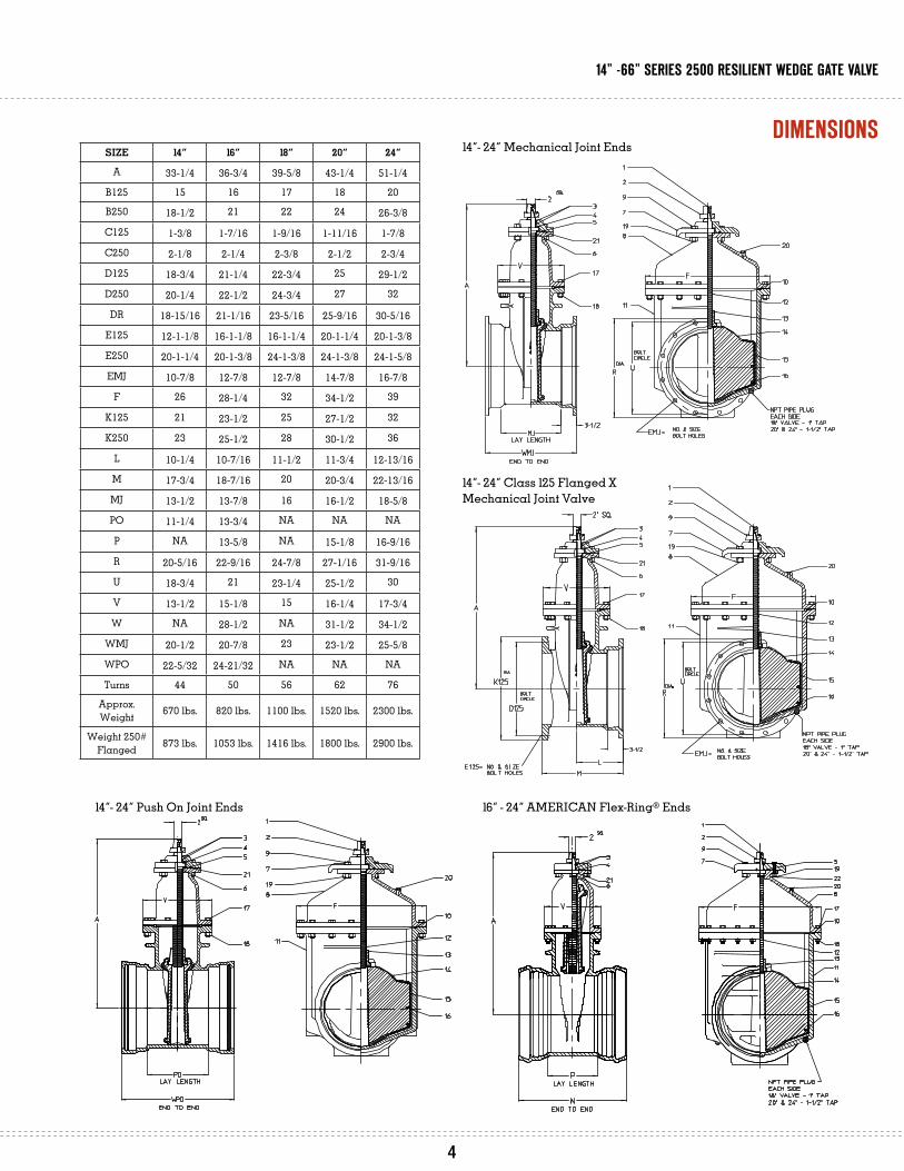
14”- 24” Mechanical Joint Ends
14”- 24” Class 125 Flanged X
Mechanical Joint Valve
14”- 24” Push On Joint Ends 16” - 24” AMERICAN Flex-Ring® Ends
size 14” 16” 18” 20” 24”
A 33-1/4 36-3/4 39-5/8 43-1/4 51-1/4
B125 15 16 17 18 20
B250 18-1/2 21 22 24 26-3/8
C125 1-3/8 1-7/16 1-9/16 1-11/16 1-7/8
C250 2-1/8 2-1/4 2-3/8 2-1/2 2-3/4
D125 18-3/4 21-1/4 22-3/4 25 29-1/2
D250 20-1/4 22-1/2 24-3/4 27 32
DR 18-15/16 21-1/16 23-5/16 25-9/16 30-5/16
E125 12-1-1/8 16-1-1/8 16-1-1/4 20-1-1/4 20-1-3/8
E250 20-1-1/4 20-1-3/8 24-1-3/8 24-1-3/8 24-1-5/8
EMJ 10-7/8 12-7/8 12-7/8 14-7/8 16-7/8
F 26 28-1/4 32 34-1/2 39
K125 21 23-1/2 25 27-1/2 32
K250 23 25-1/2 28 30-1/2 36
L 10-1/4 10-7/16 11-1/2 11-3/4 12-13/16
M 17-3/4 18-7/16 20 20-3/4 22-13/16
MJ 13-1/2 13-7/8 16 16-1/2 18-5/8
PO 11-1/4 13-3/4 NA NA NA
P NA 13-5/8 NA 15-1/8 16-9/16
R 20-5/16 22-9/16 24-7/8 27-1/16 31-9/16
U 18-3/4 21 23-1/4 25-1/2 30
V 13-1/2 15-1/8 15 16-1/4 17-3/4
W NA 28-1/2 NA 31-1/2 34-1/2
WMJ 20-1/2 20-7/8 23 23-1/2 25-5/8
WPO 22-5/32 24-21/32 NA NA NA
Turns 44 50 56 62 76
Approx. Weight 670 lbs. 820 lbs. 1100 lbs. 1520 lbs. 2300 lbs.
Weight 250# Flanged 873 lbs. 1053 lbs. 1416 lbs. 1800 lbs. 2900 lbs.
dimenSionS
3 4
14” -66” SerieS 2500 reSilient wedge gAte vAlve

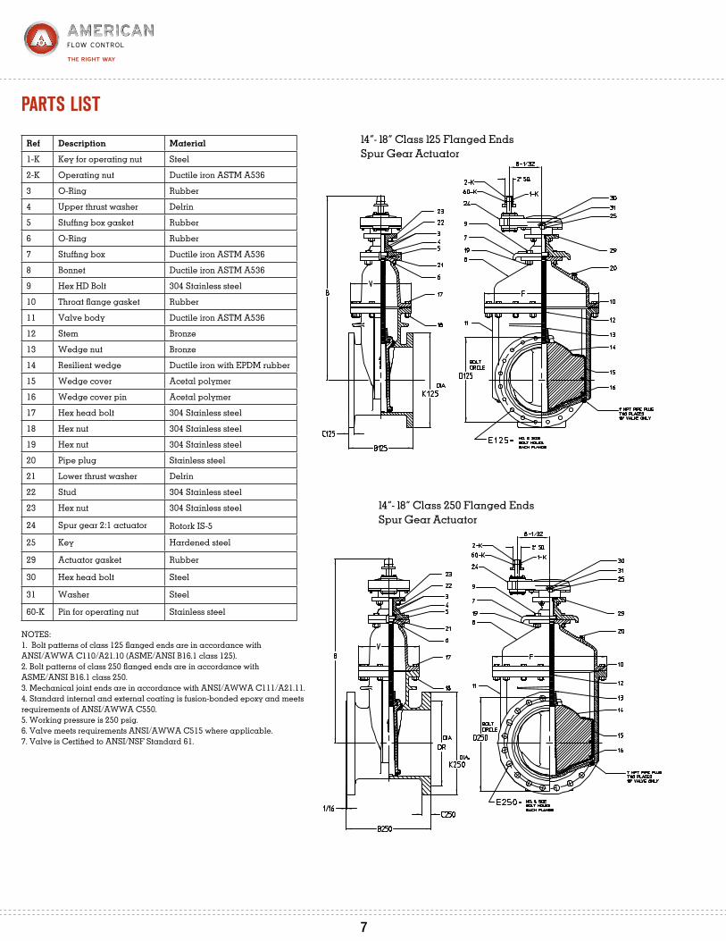
ref Description material
1-K Key for operating nut Steel
2-K Operating nut Ductile iron ASTM A536
3 O-Ring Rubber
4 Upper thrust washer Delrin
5 Stuffing box gasket Rubber
6 O-Ring Rubber
7 Stuffing box Ductile iron ASTM A536
8 Bonnet Ductile iron ASTM A536
9 Hex HD Bolt 304 Stainless steel
10 Throat flange gasket Rubber
11 Valve body Ductile iron ASTM A536
12 Stem Bronze
13 Wedge nut Bronze
14 Resilient wedge Ductile iron with EPDM rubber
15 Wedge cover Acetal polymer
16 Wedge cover pin Acetal polymer
17 Hex head bolt 304 Stainless steel
18 Hex nut 304 Stainless steel
19 Hex nut 304 Stainless steel
20 Pipe plug Stainless steel
21 Lower thrust washer Delrin
22 Stud 304 Stainless steel
23 Hex nut 304 Stainless steel
27 Bevel gear 2:1 operator Rotork IB-5
25 Key Hardened steel
29 Actuator gasket Rubber O-Ring
30 Hex head bolt Steel
31 Washer Steel
60-K Pin for operating nut Stainless steel
NOTES:1. Bolt patterns of class 125 flanged ends are in accordance with ANSI/AWWA C110/A21.10 (ASME/ANSI B16.1 class 125).2. Bolt patterns of class 250 flanged ends are in accordance with ASME/ANSI B16.1 class 250.3. Mechanical joint ends are in accordance with ANSI/AWWA C111/A21.11.4. Standard internal and external coating is fusion-bonded epoxy and meets requirements of ANSI/AWWA C550.5. Working pressure is 250 psig.6. Valve meets requirements ANSI/AWWA C515 where applicable.7. Valve is Certified to ANSI/NSF Standard 61.
14”- 18” Class 125 Flanged EndsBevel Gear Actuator
14”- 18” Class 250 Flanged EndsBevel Gear Actuator
it is consiDereD GooD Practice that When DePth oF Bury anD aPPlications alloW, Gate valves Be installeD in the vertical Position.
it is recommenDeD that the main valve stem Be in the vertical Position For raW seWeraGe aPPlications.
pArtS liSt
5 6
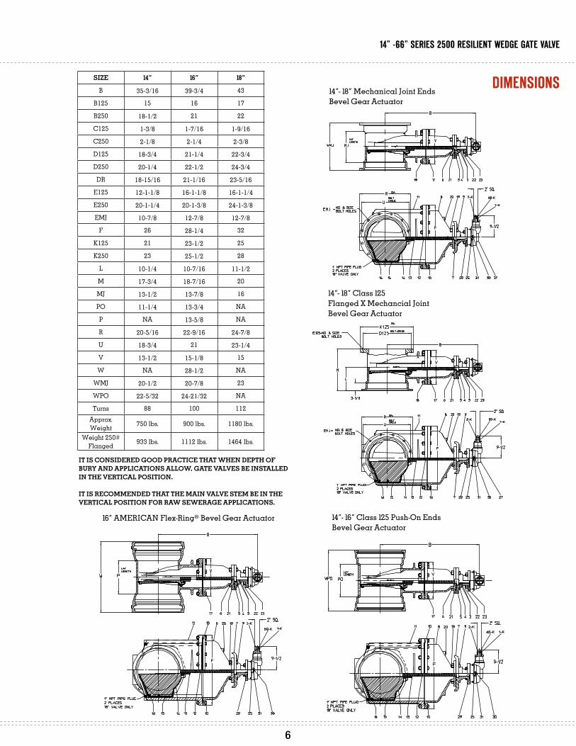
14”- 18” Mechanical Joint Ends
Bevel Gear Actuator
14”- 18” Class 125
Flanged X Mechancial Joint
Bevel Gear Actuator
14”- 16” Class 125 Push-On Ends
Bevel Gear Actuator
16” AMERICAN Flex-Ring® Bevel Gear Actuator
size 14” 16” 18”
B 35-3/16 39-3/4 43
B125 15 16 17
B250 18-1/2 21 22
C125 1-3/8 1-7/16 1-9/16
C250 2-1/8 2-1/4 2-3/8
D125 18-3/4 21-1/4 22-3/4
D250 20-1/4 22-1/2 24-3/4
DR 18-15/16 21-1/16 23-5/16
E125 12-1-1/8 16-1-1/8 16-1-1/4
E250 20-1-1/4 20-1-3/8 24-1-3/8
EMJ 10-7/8 12-7/8 12-7/8
F 26 28-1/4 32
K125 21 23-1/2 25
K250 23 25-1/2 28
L 10-1/4 10-7/16 11-1/2
M 17-3/4 18-7/16 20
MJ 13-1/2 13-7/8 16
PO 11-1/4 13-3/4 NA
P NA 13-5/8 NA
R 20-5/16 22-9/16 24-7/8
U 18-3/4 21 23-1/4
V 13-1/2 15-1/8 15
W NA 28-1/2 NA
WMJ 20-1/2 20-7/8 23
WPO 22-5/32 24-21/32 NA
Turns 88 100 112Approx. Weight 750 lbs. 900 lbs. 1180 lbs.
Weight 250# Flanged 933 lbs. 1112 lbs. 1464 lbs.
dimenSionS
5 6
14” -66” SerieS 2500 reSilient wedge gAte vAlve
it is consiDereD GooD Practice that When DePth oF Bury anD aPPlications alloW, Gate valves Be installeD in the vertical Position.
it is recommenDeD that the main valve stem Be in the vertical Position For raW seWeraGe aPPlications.
ref Description material
1-K Key for operating nut Steel
2-K Operating nut Ductile iron ASTM A536
3 O-Ring Rubber
4 Upper thrust washer Delrin
5 Stuffing box gasket Rubber
6 O-Ring Rubber
7 Stuffing box Ductile iron ASTM A536
8 Bonnet Ductile iron ASTM A536
9 Hex HD Bolt 304 Stainless steel
10 Throat flange gasket Rubber
11 Valve body Ductile iron ASTM A536
12 Stem Bronze
13 Wedge nut Bronze
14 Resilient wedge Ductile iron with EPDM rubber
15 Wedge cover Acetal polymer
16 Wedge cover pin Acetal polymer
17 Hex head bolt 304 Stainless steel
18 Hex nut 304 Stainless steel
19 Hex nut 304 Stainless steel
20 Pipe plug Stainless steel
21 Lower thrust washer Delrin
22 Stud 304 Stainless steel
23 Hex nut 304 Stainless steel
24 Spur gear 2:1 actuator Rotork IS-5
25 Key Hardened steel
29 Actuator gasket Rubber
30 Hex head bolt Steel
31 Washer Steel
60-K Pin for operating nut Stainless steel
NOTES:1. Bolt patterns of class 125 flanged ends are in accordance with ANSI/AWWA C110/A21.10 (ASME/ANSI B16.1 class 125).2. Bolt patterns of class 250 flanged ends are in accordance with ASME/ANSI B16.1 class 250.3. Mechanical joint ends are in accordance with ANSI/AWWA C111/A21.11.4. Standard internal and external coating is fusion-bonded epoxy and meets requirements of ANSI/AWWA C550.5. Working pressure is 250 psig.6. Valve meets requirements ANSI/AWWA C515 where applicable.7. Valve is Certified to ANSI/NSF Standard 61.
14”- 18” Class 125 Flanged Ends
Spur Gear Actuator
14”- 18” Class 250 Flanged Ends
Spur Gear Actuator
Optional Handwheel Available
pArtS liSt
7 8

14”- 18” Mechanical Joint Ends
Spur Gear Actuator
14”- 18” Class 125 Flanged X Mechanical Joint
Spur Gear Actuator
16” AMERICAN Flex Ring® EndsSpur Gear Actuator
14”-16” Push-On EndsSpur Gear Actuator
SIZE 14” 16” 18”
B 42 45-1/2 51-3/8
B125 15 16 17
B250 18-1/2 21 22
C125 1-3/8 1-7/16 1-9/16
C250 2-1/8 2-1/4 2-3/8
D125 18-3/4 21-1/4 22-3/4
D250 20-1/4 22-1/2 24-3/4
DR 18-15/16 21-1/16 23-5/16
E125 12-1-1/8 16-1-1/8 16-1-1/4
E250 20-1-1/4 20-1-3/8 24-1-3/8
EMJ 10-7/8 12-7/8 12-7/8
F 26 28-1/4 32
K125 21 23-1/2 25
K250 23 25-1/2 28
L 10-1/4 10-7/16 11-1/2
M 17-3/4 18-7/16 20
MJ 13-1/2 13-7/8 16
P N/A 13-5/8 N/A
PO 11-1/4 13-3/4 NA
R 20-5/16 22-9/16 24-7/8
U 18-3/4 21 23-1/4
V 13-1/2 15-1/8 15
W N/A 28-1/2 N/A
WMJ 20-1/2 20-7/8 23
WPO 22-5/32 24-21/32 NA
Turns 88 100 112
Approx. Weight 750 lbs. 900 lbs. 1180 lbs.
Weight 250# Flanged 933 lbs. 1112 lbs. 1464 lbs.
dimenSionS
7 8
14” -66” SerieS 2500 reSilient wedge gAte vAlve
ref Description material
1-K Key for operating nut Steel
2-K Operating nut 2” sq. Ductile iron ASTM A536
3 O-Ring Rubber
4 Upper thrust washer Delrin
5 Stuffing box gasket Rubber
6 O-Ring Rubber
7 Stuffing box Ductile iron ASTM A536
8 Bonnet Ductile iron ASTM A536
10 Throat flange gasket Rubber
11 Valve body Ductile iron ASTM A536
12 Stem Bronze
13 Wedge nut Bronze
14 Resilient wedge Ductile iron with EPDM rubber
15 Wedge cover Acetal polymer
16 Wedge cover pin Acetal polymer
17 Hex head bolt 304 Stainless steel
18 Hex nut 304 Stainless steel
20 Pipe plug 300 Series stainless steel
21 Lower thrust washer Delrin
22 Stud 304 Stainless steel
23 Hex nut 304 Stainless steel
25 Key Hardened steel
27 Bevel gear actuator See table
28 Socket head capscrew 304 Stainless steel
29 Actuator gasket Rubber
30 Hex head bolt Zinc-plated steel
31 Washer Steel
60-K Pin for operating nut Stainless steel
NOTES:1. Bolt patterns of class 125 flanged ends are in accordance with ANSI/AWWA C110/A21.10 (ASME/ANSI B16.1 class 125).2. Bolt patterns of class 250 flanged ends are in accordance with ASME/ANSI B16.1 class 250.3. Mechanical joint ends are in accordance with ANSI/AWWA C111/A21.11.4. Push-on joint design is AMERICAN Flex-Ring®.5. Standard internal and external coating is fusion-bonded epoxy and meets requirements of ANSI/AWWA C550.6. Working pressure is 250 psig.7. Valve meets requirements ANSI/AWWA C515 where applicable.8. Valve is Certified to ANSI/NSF Standard 61.
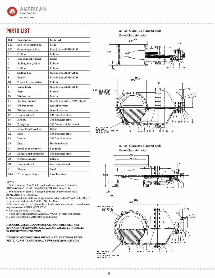
20”-36” Class 125 Flanged EndsBevel Gear Actuator
20”-36” Class 250 Flanged EndsBevel Gear Actuator
pArtS liSt
9
it is consiDereD GooD Practice that When DePth oF Bury anD aPPlications alloW, Gate valves Be installeD in the vertical Position.
it is recommenDeD that the main valve stem Be in the vertical Position For raW seWeraGe aPPlications.
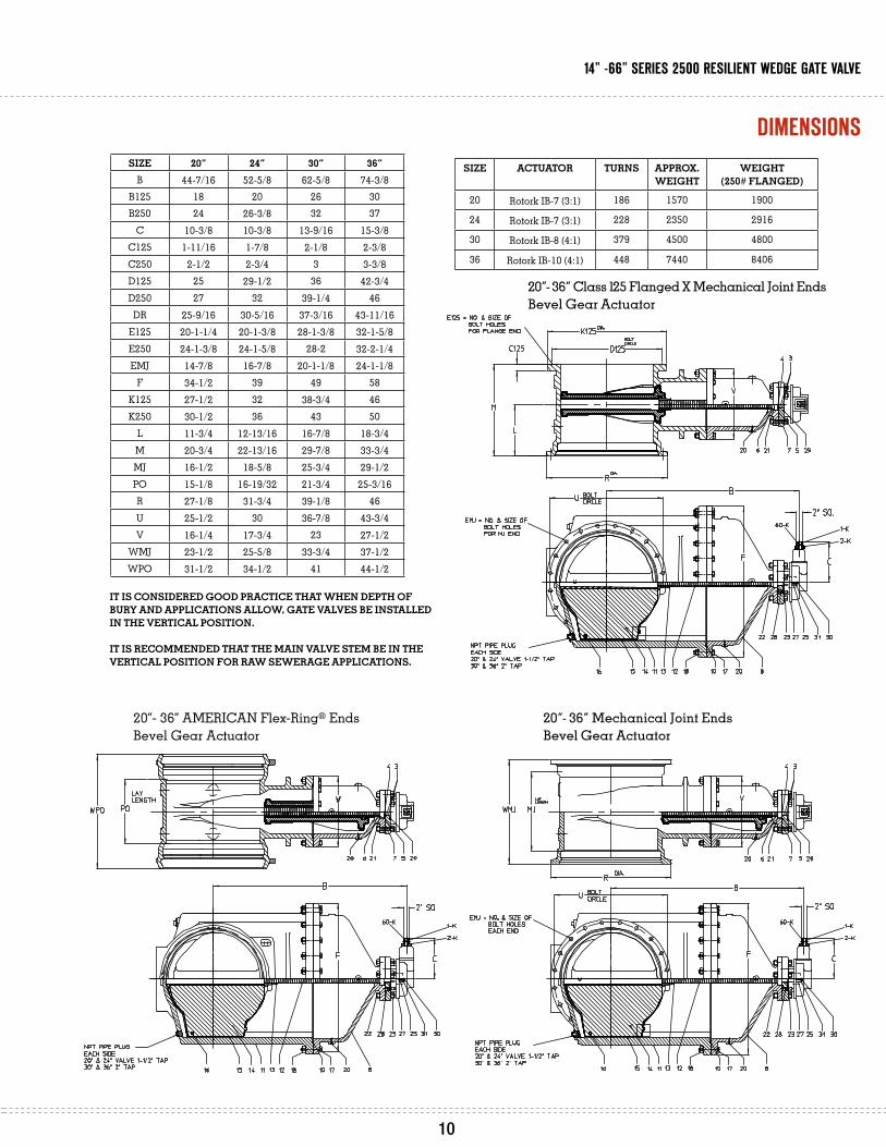
20”- 36” AMERICAN Flex-Ring® EndsBevel Gear Actuator
20”- 36” Mechanical Joint Ends
Bevel Gear Actuator
20”- 36” Class 125 Flanged X Mechanical Joint Ends
Bevel Gear Actuator
size 20” 24” 30” 36”B 44-7/16 52-5/8 62-5/8 74-3/8
B125 18 20 26 30B250 24 26-3/8 32 37
C 10-3/8 10-3/8 13-9/16 15-3/8C125 1-11/16 1-7/8 2-1/8 2-3/8C250 2-1/2 2-3/4 3 3-3/8D125 25 29-1/2 36 42-3/4D250 27 32 39-1/4 46DR 25-9/16 30-5/16 37-3/16 43-11/16
E125 20-1-1/4 20-1-3/8 28-1-3/8 32-1-5/8E250 24-1-3/8 24-1-5/8 28-2 32-2-1/4EMJ 14-7/8 16-7/8 20-1-1/8 24-1-1/8
F 34-1/2 39 49 58K125 27-1/2 32 38-3/4 46K250 30-1/2 36 43 50
L 11-3/4 12-13/16 16-7/8 18-3/4M 20-3/4 22-13/16 29-7/8 33-3/4MJ 16-1/2 18-5/8 25-3/4 29-1/2PO 15-1/8 16-19/32 21-3/4 25-3/16R 27-1/8 31-3/4 39-1/8 46U 25-1/2 30 36-7/8 43-3/4V 16-1/4 17-3/4 23 27-1/2
WMJ 23-1/2 25-5/8 33-3/4 37-1/2WPO 31-1/2 34-1/2 41 44-1/2
size actuator turns aPProx.WeiGht
WeiGht (250# FlanGeD)
20 Rotork IB-7 (3:1) 186 1570 1900
24 Rotork IB-7 (3:1) 228 2350 2916
30 Rotork IB-8 (4:1) 379 4500 4800
36 Rotork IB-10 (4:1) 448 7440 8406
dimenSionS
9 10
14” -66” SerieS 2500 reSilient wedge gAte vAlve
it is consiDereD GooD Practice that When DePth oF Bury anD aPPlications alloW, Gate valves Be installeD in the vertical Position.
it is recommenDeD that the main valve stem Be in the vertical Position For raW seWeraGe aPPlications.
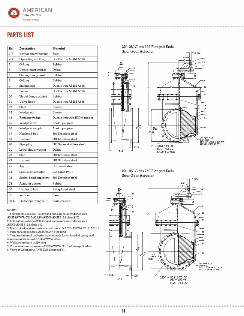
ref Description material
1-K Key for operating nut Steel
2-K Operating nut 2” sq. Ductile iron ASTM A536
3 O-Ring Rubber
4 Upper thrust washer Delrin
5 Stuffing box gasket Rubber
6 O-Ring Rubber
7 Stuffing box Ductile iron ASTM A536
8 Bonnet Ductile iron ASTM A536
10 Throat flange gasket Rubber
11 Valve body Ductile iron ASTM A536
12 Stem Bronze
13 Wedge nut Bronze
14 Resilient wedge Ductile iron with EPDM rubber
15 Wedge cover Acetal polymer
16 Wedge cover pin Acetal polymer
17 Hex head bolt 304 Stainless steel
18 Hex nut 304 Stainless steel
20 Pipe plug 300 Series stainless steel
21 Lower thrust washer Delrin
22 Stud 304 Stainless steel
23 Hex nut 304 Stainless steel
25 Key Hardened steel
24 Spur gear actuator See table Pg.12
28 Socket head capscrew 304 Stainless steel
29 Actuator gasket Rubber
30 Hex head bolt Zinc-plated steel
31 Washer Steel
60-K Pin for operating nut Stainless steel
NOTES:1. Bolt patterns of class 125 flanged ends are in accordance with ANSI/AWWA C110/A21.10 (ASME/ANSI B16.1 class 125).2. Bolt patterns of class 250 flanged ends are in accordance with ASME/ANSI B16.1 class 250.3. Mechanical joint ends are accordance with ANSI/AWWA C111/A21.11.4. Push-on joint design is AMERICAN Flex Ring®.5. Standard internal and external coating is fusion-bonded epoxy and meets requirements of ANSI/AWWA C550.6. Working pressure is 250 psig.7. Valve meets requirements ANSI/AWWA C515 where applicable.8. Valve is Certified to ANSI/NSF Standard 61.
20”- 36” Class 125 Flanged EndsSpur Gear Actuator
20”- 36” Class 250 Flanged EndsSpur Gear Actuator
pArtS liSt
11

20”- 36” AMERICAN Flex-Ring
® Ends
Boltless Restrained Joint Spur Gear Actuator
20”- 36” Mechanical Joint Ends
Spur Gear Actuator
20”- 36” Class 125 Flanged X Mechanical Joint Valve
Spur Gear Actuator
size 20” 24” 30” 36”
A 49-1/2 57-5/8 71 83
B125 18 20 26 30
B250 24 26-3/8 32 37
C 12 12 13-1/8 14
C125 1-11/16 1-7/8 2-1/8 2-3/8
C250 2-1/2 2-3/4 3 3-3/8
D125 25 29-1/2 36 42-3/4
D250 27 32 39-1/4 46
DR 25-9/16 30-5/16 37-3/16 43-11/16
E125 20-1-1/4 20-1-3/8 28-1-3/8 32-1-5/8
E250 24-1-3/8 24-1-5/8 28-2 32-2-1/4
EMJ 14-7/8 16-7/8 20-1-1/8 24-1-1/8
F 34-1/2 39 49 58
K125 27-1/2 32 38-3/4 46
K250 30-1/2 36 43 50
L 11-3/4 12-13/16 16-7/8 18-3/4
M 20-3/4 22-13/16 29-7/8 33-3/4
MJ 16-1/2 18-5/8 25-3/4 29-1/2
PO NA 16-19/32 21-3/4 25-3/16
R 27-1/8 31-3/4 39-1/8 46
U 25-1/2 30 36-7/8 43-3/4
V 16-1/4 17-3/4 23 27-1/2
WMJ 23-1/2 25-5/8 33-3/4 37-1/2
WPO NA 34-1/2 41 44-1/2
size actuator turns aPProx.WeiGht
WeiGht (250# FlanGeD)
20 Rotork IS-7 (3:1) 186 1570 1900
24 Rotork IS-7 (3:1) 228 2350 2916
30 Rotork IS-8 (4:1) 379 4600 4800
36 Rotork IS-10 (4:1) 448 7440 8417
dimenSionS
11 12
14” -66” SerieS 2500 reSilient wedge gAte vAlve

ref Description material1-K Key for operating nut Steel
2-K Operating nut 2” sq. Ductile iron ASTM A5363 O-Ring Rubber4 Upper thrust washer Delrin5 Stuffing box gasket Rubber6 O-Ring Rubber7 Stuffing box Ductile iron ASTM A5368 Bonnet Ductile iron ASTM A53610 Throat flange gasket Rubber11 Valve body Ductile iron ASTM A53612 Stem Bronze13 Wedge nut Bronze14 Resilient wedge Ductile iron with EPDM rubber15 Wedge cover Acetal polymer16 Wedge cover pin Acetal polymer17 Hex head bolt 304 Stainless steel18 Hex nut 304 Stainless steel20 Pipe plug 300 Series stainless steel21 Lower thrust washer Delrin22 Stud 304 Stainless steel23 Hex nut 304 Stainless steel
25 Key Hardened steel
27 Bevel gear actuator Rotork IB-12 (8:1)
28 Socket head capscrew 304 Stainless steel
29 Actuator gasket Rubber
30 Hex head bolt Zinc-plated steel
31 Washer Steel
50-K Set screw for operating nut Stainless steel
NOTES:1. Bolt patterns of class 125 flanged ends are in accordance with ANSI/AWWA C110/A21.10 (ASME/ANSI B16.1 class 125).2. Bolt patterns of class 250 flanged ends are in accordance with ASME/ANSI B16.1 class 250.3. Standard internal and external coating is fusion-bonded epoxy and meets requirements of ANSI/AWWA C550 for 42” & 48”.4. Working pressure is 250 psig.5. Open direction as specified by customer.6. Valve meets requirements ANSI/AWWA C515 where applicable.7. Valve is Certified to ANSI/NSF Standard 61.
NOTES: 54” Class 125 Flanges Bevel Gear:1. Bolt patterns of class 125 flanged ends are in accordance with ANSI/AWWA C110/A21.10 (ASME/ANSI B16.1 class 125).2. Standard internal and external coating is liquid epoxy for 54”.3. Working pressure is 250 psig.4. Open direction as specified by customer.5. Turns to open 789.6. Weight 17,054 lbs.7. Valve meets requirements ANSI/AWWA C515 where applicable.8. Valve is Certified to ANSI/NSF Standard 61.
42”- 54” Class 125 Flanged EndsBevel Gear Actuator
42”- 48” Class 250 Flanged EndsBevel Gear Actuator
pArtS liSt
13
it is consiDereD GooD Practice that When DePth oF Bury anD aPPlications alloW, Gate valves Be installeD in the vertical Position.
it is recommenDeD that the main valve stem Be in the vertical Position For raW seWeraGe aPPlications.

42”- 48” AMERICAN Flex-Ring® EndsBevel Gear Actuator
42”- 48” Mechanical Joint X Mechanical Joint
Bevel Gear Actuator
42”- 54” Class 125 Flanged X Mechanical Joint Ends
Bevel Gear Actuator
size 42” 48” 54”B 86-9/32 96 96
B125 38 43 48B250 40 46-1/4 NAC125 2-5/8 2-3/4 3C250 3-11/16 4 NAD125 49-1/2 56 62-3/4D250 52-3/4 60-3/4 NADR 50-7/16 58-7/16 NA
E125 36-1-5/8 44-1-5/8 44-2E250 36-2-1/4 40-2-1/4 NAEMJ 28-1-3/8 32-1-3/8 NA
F 66-3/4 75-1/2 75-1/2H 42-3/8 48-3/8 48-3/8
K125 53 59-1/2 66-1/4K250 57 65 NA
L 23-3/8 22-1/2 NAM 42-3/8 44 NAMJ 38-3/4 37 NAPO 31-13/16 37-17/64 NAR 53-1/8 60 NAU 50-5/8 57-1/2 NAV 31-1/4 34-1/4 34-1/4
WMJ 46-3/4 45 NAWPO 53-1/2 62 NA
Actuator Rotork IB-12 (8:1)
Rotork IB-12 (8:1)
Rotork IB-12 (8:1)
Approx. Weight 11,279 lbs. 15,870 lbs. 17,054 lbs.Weight
250# Flanged 15,930 lbs. 17,713 lbs. NA
Turns 694 789 789
13 14
14” -66” SerieS 2500 reSilient wedge gAte vAlve
dimenSionS
it is consiDereD GooD Practice that When DePth oF Bury anD aPPlications alloW, Gate valves Be installeD in the vertical Position.
it is recommenDeD that the main valve stem Be in the vertical Position For raW seWeraGe aPPlications.
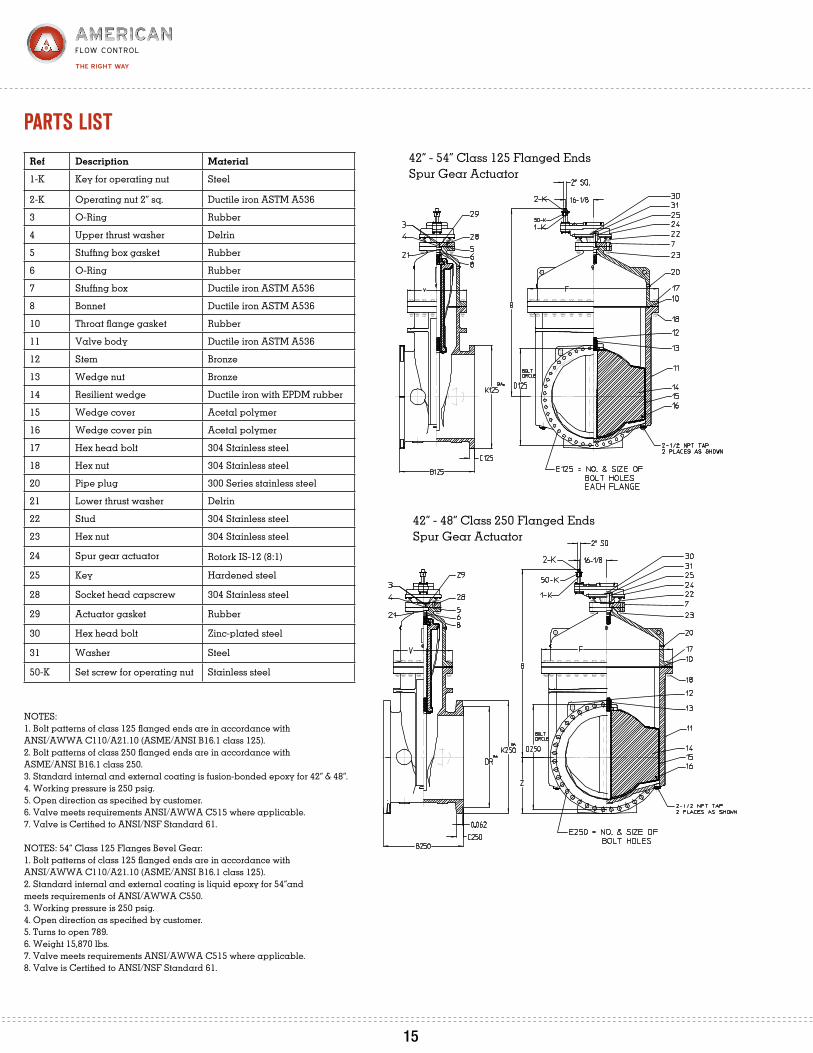
ref Description material
1-K Key for operating nut Steel
2-K Operating nut 2” sq. Ductile iron ASTM A536
3 O-Ring Rubber
4 Upper thrust washer Delrin
5 Stuffing box gasket Rubber
6 O-Ring Rubber
7 Stuffing box Ductile iron ASTM A536
8 Bonnet Ductile iron ASTM A536
10 Throat flange gasket Rubber
11 Valve body Ductile iron ASTM A536
12 Stem Bronze
13 Wedge nut Bronze
14 Resilient wedge Ductile iron with EPDM rubber
15 Wedge cover Acetal polymer
16 Wedge cover pin Acetal polymer
17 Hex head bolt 304 Stainless steel
18 Hex nut 304 Stainless steel
20 Pipe plug 300 Series stainless steel
21 Lower thrust washer Delrin
22 Stud 304 Stainless steel
23 Hex nut 304 Stainless steel
24 Spur gear actuator Rotork IS-12 (8:1)
25 Key Hardened steel
28 Socket head capscrew 304 Stainless steel
29 Actuator gasket Rubber
30 Hex head bolt Zinc-plated steel
31 Washer Steel
50-K Set screw for operating nut Stainless steel
NOTES:1. Bolt patterns of class 125 flanged ends are in accordance with ANSI/AWWA C110/A21.10 (ASME/ANSI B16.1 class 125).2. Bolt patterns of class 250 flanged ends are in accordance with ASME/ANSI B16.1 class 250.3. Standard internal and external coating is fusion-bonded epoxy for 42” & 48”.4. Working pressure is 250 psig.5. Open direction as specified by customer.6. Valve meets requirements ANSI/AWWA C515 where applicable.7. Valve is Certified to ANSI/NSF Standard 61.
NOTES: 54” Class 125 Flanges Bevel Gear:1. Bolt patterns of class 125 flanged ends are in accordance with ANSI/AWWA C110/A21.10 (ASME/ANSI B16.1 class 125).2. Standard internal and external coating is liquid epoxy for 54”and meets requirements of ANSI/AWWA C550.3. Working pressure is 250 psig.4. Open direction as specified by customer.5. Turns to open 789.6. Weight 15,870 lbs.7. Valve meets requirements ANSI/AWWA C515 where applicable.8. Valve is Certified to ANSI/NSF Standard 61.
42” - 48” Class 250 Flanged EndsSpur Gear Actuator
42” - 54” Class 125 Flanged EndsSpur Gear Actuator
15
pArtS liSt
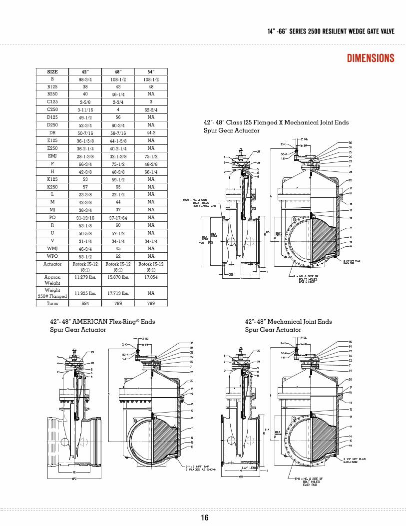
42”- 48” AMERICAN Flex-Ring® Ends
Spur Gear Actuator
42”- 48” Mechanical Joint Ends
Spur Gear Actuator
42”- 48” Class 125 Flanged X Mechanical Joint Ends
Spur Gear Actuator
size 42” 48” 54”B 98-3/4 108-1/2 108-1/2
B125 38 43 48B250 40 46-1/4 NAC125 2-5/8 2-3/4 3C250 3-11/16 4 62-3/4D125 49-1/2 56 NAD250 52-3/4 60-3/4 NADR 50-7/16 58-7/16 44-2
E125 36-1/5/8 44-1-5/8 NAE250 36-2-1/4 40-2-1/4 NAEMJ 28-1-3/8 32-1-3/8 75-1/2
F 66-3/4 75-1/2 48-3/8H 42-3/8 48-3/8 66-1/4
K125 53 59-1/2 NAK250 57 65 NA
L 23-3/8 22-1/2 NAM 42-3/8 44 NAMJ 38-3/4 37 NAPO 31-13/16 37-17/64 NAR 53-1/8 60 NAU 50-5/8 57-1/2 NAV 31-1/4 34-1/4 34-1/4
WMJ 46-3/4 45 NAWPO 53-1/2 62 NA
Actuator Rotork IS-12 (8:1)
Rotork IS-12 (8:1)
Rotork IS-12 (8:1)
Approx. Weight
11,279 lbs. 15,870 lbs. 17,054
Weight 250# Flanged 11,925 lbs. 17,713 lbs. NA
Turns 694 789 789
15 16
14” -66” SerieS 2500 reSilient wedge gAte vAlve
dimenSionS

ref Description material
1-K Key Steel
2-K Operating nut 2” sq. Ductile iron ASTM A536
3 O-Ring Rubber
4 Upper thrust washer Delrin
5 Stuffing box gasket Rubber
6 O-Ring Rubber
7 Stuffing box Ductile iron ASTM A536
8 Bonnet Ductile iron ASTM A536
10 Throat flange gasket Rubber
11 Valve body Ductile iron ASTM A536
12 Stem Stainless steel
13 Wedge nut Bronze
14 Resilient wedge Ductile iron with EPDM rubber
15 Wedge cover Acetal polymer
16 Wedge cover pin Acetal polymer
17 Hex head bolt 304 Stainless steel
18 Hex nut 304 Stainless steel
20 Pipe plug 300 Series stainless steel
21 Lower thrust washer Delrin
22 Stud 304 Stainless steel
23 Hex nut 304 Stainless steel
25 Key Hardened steel
27 Bevel gear actuator Rotork IB-12 (8:1)
28 Socket head capscrew 304 Stainless steel
29 Actuator gasket Rubber
30 Hex head bolt 304 Stainless steel
31 Washer Steel
50-K Set screw for operating nut Stainless steel
55 Blind flange Ductile iron
56 Studs Stainless steel
57 Nuts Stainless steel
NOTES:1. Bolt patterns are in accordance per ANSI/AWWA C207 class E.2. Standard internal and external coating is liquid epoxy for 60” and 66” and meets requirements of ANSI/AWWA C550.3. Working pressure is 250 psig.4. Open direction as specified by customer.5. Weight 31,618 lbs.6. Turns to open 984.7. Valve meets requirements ANSI/AWWA C515 where applicable.8. Valve is Certified to ANSI/NSF Standard 61.
60” Flanged Ends - Bevel Gear Actuator
66” Flanged Ends - Bevel Gear Actuator
pArtS liSt/ dimenSionS
17
it is consiDereD GooD Practice that When DePth oF Bury anD aPPlications alloW, Gate valves Be installeD in the vertical Position.
it is recommenDeD that the main valve stem Be in the vertical Position For raW seWeraGe aPPlications.
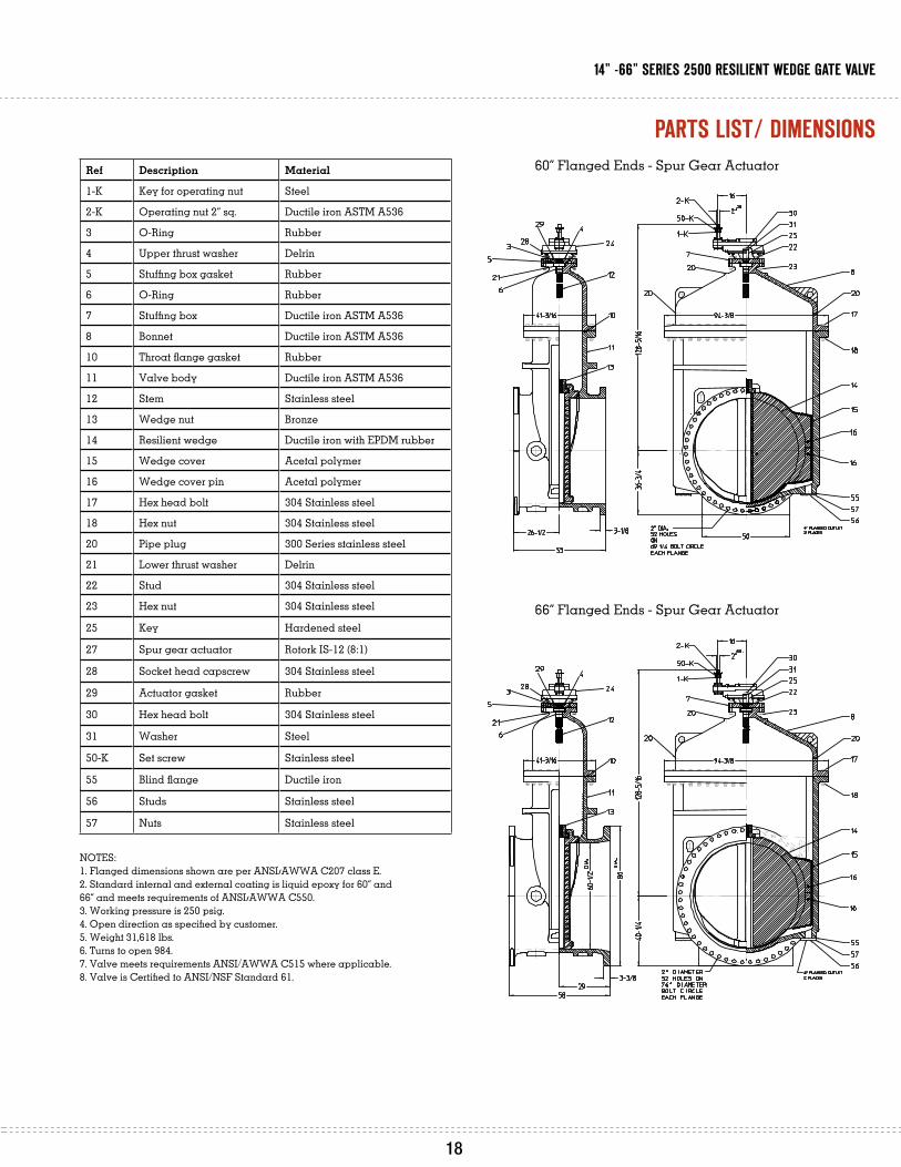
ref Description material
1-K Key for operating nut Steel
2-K Operating nut 2” sq. Ductile iron ASTM A536
3 O-Ring Rubber
4 Upper thrust washer Delrin
5 Stuffing box gasket Rubber
6 O-Ring Rubber
7 Stuffing box Ductile iron ASTM A536
8 Bonnet Ductile iron ASTM A536
10 Throat flange gasket Rubber
11 Valve body Ductile iron ASTM A536
12 Stem Stainless steel
13 Wedge nut Bronze
14 Resilient wedge Ductile iron with EPDM rubber
15 Wedge cover Acetal polymer
16 Wedge cover pin Acetal polymer
17 Hex head bolt 304 Stainless steel
18 Hex nut 304 Stainless steel
20 Pipe plug 300 Series stainless steel
21 Lower thrust washer Delrin
22 Stud 304 Stainless steel
23 Hex nut 304 Stainless steel
25 Key Hardened steel
27 Spur gear actuator Rotork IS-12 (8:1)
28 Socket head capscrew 304 Stainless steel
29 Actuator gasket Rubber
30 Hex head bolt 304 Stainless steel
31 Washer Steel
50-K Set screw Stainless steel
55 Blind flange Ductile iron
56 Studs Stainless steel
57 Nuts Stainless steel
NOTES:1. Flanged dimensions shown are per ANSI/AWWA C207 class E.2. Standard internal and external coating is liquid epoxy for 60” and 66” and meets requirements of ANSI/AWWA C550.3. Working pressure is 250 psig.4. Open direction as specified by customer.5. Weight 31,618 lbs.6. Turns to open 984.7. Valve meets requirements ANSI/AWWA C515 where applicable.8. Valve is Certified to ANSI/NSF Standard 61.
60” Flanged Ends - Spur Gear Actuator
66” Flanged Ends - Spur Gear Actuator
pArtS liSt/ dimenSionS
17 18
14” -66” SerieS 2500 reSilient wedge gAte vAlve
american Flow control
P.O. Box 2727Birmingham, AL 35202-2727Phone: 1-800-326-8051Fax: 1-800-610-3569E-mail: [email protected]
Waterous company
125 Hardman Avenue SouthSouth St. Paul, MN 55075-1191Phone: 1-888-266-3686Fax: 1-800-601-2809E-mail: [email protected]
www.AmericAn-uSA.com
Distributed By:
AFC-3/11 - PDF
F LOW CONTROL