Residue Pipeline Measurement Policy - Westcoast Energy · PDF fileResidue Pipeline System...
67
Residue Pipeline System Measurement Policy Prepared by: Measurement Technical Services Revision Tracking Date Created 2001 Last Updated 04/13/2015 Revision 3.0 Measurement Technical Services, BC Pipeline and Field Services
Transcript of Residue Pipeline Measurement Policy - Westcoast Energy · PDF fileResidue Pipeline System...

Residue Pipeline System Measurement Policy
Prepared by: Measurement Technical Services
Revision Tracking
Date Created 2001
Last Updated 04/13/2015
Revision 3.0
Measurement Technical Services, BC Pipeline and Field Services
Shipper Handbook Residue Pipeline System Measurement Policy
Prepare by: Measurement Technical Services -ii- Last updated: 04/13/2015
Table of Contents
7.1 GAS MEASUREMENT ........................................................................................................ 1
7.1.1Policy Requirements ............................................................................................... 1
7.1.2Inspection Requirements ........................................................................................ 2
7.1.3Gas Contract Hour (Start Time) and Clock Settings .................................................... 2
7.1.4Conversion Factors ................................................................................................ 4
7.2 MEASUREMENT RESPONSIBILITIES ....................................................................................... 4
7.2.1Metering Point Installation Requirements .................................................................. 5
7.2.1.1Interconnecting with BC Pipeline and Field Services Residue Transmission System ... 5
7.2.1.2Facility Design Requirements Related to Volume .................................................. 6
7.2.2Interconnecting with BC Pipeline and Field Services RGT ............................................ 6
7.2.3Notification to BC Pipeline and Field Services ............................................................ 6
7.3 PRIMARY GAS MEASUREMENT ............................................................................................ 6
7.3.1Orifice Metering ..................................................................................................... 7
7.3.1.1 General ......................................................................................................... 7
7.3.1.2Installation ...................................................................................................... 7
7.3.2Turbine Metering ................................................................................................... 2
7.3.2.1General .......................................................................................................... 2
7.3.2.2Installation ...................................................................................................... 2
7.3.3Rotary Metering .................................................................................................... 3
7.3.3.1General .......................................................................................................... 3
7.3.3.2Installation ...................................................................................................... 3
7.3.4Diaphragm Metering .............................................................................................. 4
7.3.4.1General .......................................................................................................... 4
7.3.4.2Installation ...................................................................................................... 4
7.3.5Ultrasonic Metering ................................................................................................ 4
7.3.5.1General .......................................................................................................... 5
7.3.5.2Installation ...................................................................................................... 5
7.3.6Mass Flow Metering ............................................................................................... 6
7.3.6.1General .......................................................................................................... 6
7.3.6.2Installation ...................................................................................................... 6
7.4 TERTIARY DEVICE -CHART MEASUREMENT .............................................................................. 6
7.4.1Chart Recorder and Mechanical Integrators ............................................................... 6
7.4.1.1General .......................................................................................................... 6
7.4.1.2Reporting ........................................................................................................ 7
7.5 TERTIARY DEVICE-ELECTRONIC FLOW MEASUREMENT ................................................................ 7
7.5.1General ................................................................................................................ 7
7.5.1.1EFM Communication Requirements ................................................................... 10
7.5.1.2Polling Interval/Frequency ............................................................................... 11
7.5.1.3EFM Time-sync Requirements .......................................................................... 12
7.5.2Installation ......................................................................................................... 12
7.5.3Data Requirements .............................................................................................. 13
7.5.3.1Gas Measurement Data ................................................................................... 13
7.5.3.2Report and Audit Functions ............................................................................. 14
7.6 PROCEDURES FOR VERIFICATION AND CALIBRATION OF EFM - GAS ONLY ....................................... 14
7.6.1General .............................................................................................................. 14
7 MEASUREMENT POLICY ................................................................................................. 1

Shipper Handbook Residue Pipeline System Measurement Policy
Prepare by: Measurement Technical Services -iii- Last updated: 04/13/2015
7.6.2Verification ......................................................................................................... 15
7.6.3Calibration .......................................................................................................... 16
7.6.4Calibration Test Instrumentation ........................................................................... 17
7.7 PLANT PRODUCT METERING ............................................................................................. 18
7.8 CONDENSATE METERING ................................................................................................ 18
7.9 LIQUID METER PROVING ................................................................................................ 18
7.10 .................................................................................... ANALYSIS DATA AND DETERMINATION
18
7.10.1Laboratory Requirements .................................................................................... 18
7.10.1.Laboratory Quality Control .............................................................................. 19
7.10.2Component Analyses Requirements – Raw Gas System .......................................... 19
7.10.3Component Analyses Requirements – Residue Gas Transmission System .................. 19
7.10.3.1Standard Gas Analysis .................................................................................. 19
7.10.3.2Electronic Date Interface ............................................................................... 19
7.10.4On-line Analyzers .............................................................................................. 20
7.10.4.1Gas Chromatograph ..................................................................................... 20
7.10.4.1.1Equipment ............................................................................................. 20
7.10.4.1.2GC Sampling Requirements ...................................................................... 21
7.10.4.2H2S and Total Sulphur Analyzer...................................................................... 21
7.10.4.2.1Equipment ............................................................................................. 21
7.10.4.2.2Sulphur Sampling Requirements ............................................................... 21
7.10.4.3H20 (Moisture) Analyzers ............................................................................... 21
7.10.4.3.1Equipment ............................................................................................. 22
7.10.4.3.2H2O Sampling Requirements .................................................................... 22
7.10.5Gas Sampling .................................................................................................... 22
7.10.5.1General ....................................................................................................... 22
7.10.5.1.1EFM Receipt Points .................................................................................. 23
7.10.5.1.2Mechanical Chart Based Measurement Facilities .......................................... 23
7.10.5.1.3Receipt Points With Liquid Metering ........................................................... 23
7.10.5.2Gas Sampling in the Raw Gas Transmission System ......................................... 23
7.10.5.2.1Solution Gas Well Tie-in Points ................................................................. 24
7.10.5.2.2Well Sampling Frequency ......................................................................... 24
7.10.5.2.3Manual Gas Spot Samples........................................................................ 24
7.10.5.3Liquid Sampling at Receipt points in the Raw Gas Transmission System .............. 24
7.10.5.3.1Manual liquid Spot Samples ..................................................................... 24
7.11 ................................................................................... MEASUREMENT DATA AND REPORTING
24
7.11.1Gas Metering Reports ......................................................................................... 24
7.11.1.1Daily Gas Volume Report ............................................................................... 24
7.11.1.2Gas Meter Report ......................................................................................... 25
7.11.1.3Monthly Gas Volume Report ........................................................................... 26
7.11.2Liquid Metering Reports ...................................................................................... 27
7.11.3Alarm Report ..................................................................................................... 27
7.11.4Data Communications ........................................................................................ 27
7.11.4.1Reports ....................................................................................................... 28
7.12 .................................................................................................. MEASUREMENT AUDITING
28
7.12.1General ............................................................................................................ 28
7.12.2Transmission Pipeline and Dry Gas RP Auditing Process .......................................... 28
7.13 .........................................................................ORDERING OF CUSTODY TRANSFER EQUIPMENT
29
7.13.1General ............................................................................................................ 29
7.13.2BC Pipeline and Field Services Badge Number Requirements – Gas Equipment Only ... 29
7.13.3Approval of Type, Inspection and Certification ....................................................... 29
Shipper Handbook Residue Pipeline System Measurement Policy
Prepare by: Measurement Technical Services -iv- Last updated: 04/13/2015
7.13.4Gas Measurement Equipment Special Requirements ............................................... 30
7.13.4.1Orifice Meter Runs ........................................................................................ 30
7.13.4.2Turbine Meters ............................................................................................. 30
7.13.4.3Ultrasonic Meters ......................................................................................... 30
7.13.4.4Mass Flow Meters ......................................................................................... 31
7.13.4.5Rotary and Diaphragm Meters ....................................................................... 31
7.13.4.6Measurement Canada Sealing Period .............................................................. 31
7.14 ......................................................................................................... DOWNSTREAM TAPS
32
7.14.1BC Pipeline and Field Services Residue Gas Transmission Downstream Taps .............. 32
7.14.1.1Bi-Directional and Interconnecting metering Facilities ....................................... 32
7.14.2Raw Gas Transmission Downstream Taps.............................................................. 32
7.14.3Exception Measurement Facilities Requirements (RGT) ........................................... 32
Not applicable to this policy. ...................................................................................... 32
7.14.3.1Verification and Calibration of Measurement Equipment .................................... 32
7.15 ............................................................................................................ TAP APPLICATION
33
7.15.1Operator of the Measurement Facility or Customers Responsibilities ......................... 33
7.15.1.1Information Requirements to be Fulfilled Prior to Construction ........................... 33
7.15.1.2Design Requirements – Receipt or Customer Delivery Facilities .................... 34
APPENDIX A – MEASUREMENT FORMS ............................................................................ A
APPENDIX B - OPERATOR OF THE MEASUREMENT FACILITIES REMOTE RADIO
SPECIFICATION .............................................................................................................. B
APPENDIX C - EFM COMMUNICATIONS CONFIGURATION PARAMETERS FOR UHF RADIO C
APPENDIX D - EFM COMMUNICATIONS CONFIGURATION PARAMETERS FOR DIAL-UP ... D
APPENDIX E - EXAMPLES OF CALIBRATION EQUIPMENT ................................................. E
APPENDIX H - CHECKLIST FOR NATURAL GAS SPOT SAMPLING ...................................... F
APPENDIX I - MEASUREMENT REPORT EXAMPLES .......................................................... G
APPENDIX J – REFERENCES ............................................................................................ H
APPENDIX K: ORIFICE METER RUN AND PLATE INSPECTION AND TESTING
REQUIREMENTS ............................................................................................................... I

Shipper Handbook Residue Pipeline System Measurement Policy
Prepare by: Measurement Technical Services -1- Last updated: 04/13/2015
7 Measurement Policy
7.1 Gas Measurement
This section deals with the policies and standards applicable to the custody transfer measurement
of natural gas within the Spectra Energy Transmission (SET or BC Pipeline and Field Services)
pipeline system, related to custody transfer measurement. Measurement requirements were
based on industry and regulatory practices. These practices were defined through standards and
regulations from the following:
American Gas Association (AGA);
Electricity and Gas Inspection Act;
And, Gas Processors Association (GPA).
Other measurement references related to contractual obligations of BC Pipeline and Field Service’s
customers are found in the BC Pipeline and Field Services General Terms and Conditions
(“GT&C”, “Pipeline Tariff”) in Articles 13 through 15. The GT&C is the governing standard at all
times where there is conflict or duplication of information between this policy and the GT&C.
This document is reviewed and updated periodically.
7.1.1 Policy Requirements
The standards and regulatory requirements to be adhered to are as follows:
1. Volumes and energy shall be reported in SI units. All other measurement data, such as
temperature and pressure, can be reported in either SI or Imperial units but must be
consistent once selected. The preferred unit of measure is SI. Conversion between Metric
and Imperial units at various standard conditions is given in Section 7.1.4 - Conversion
Factors.
2. The volumes of gas shall be measured and computed in accordance with the third edition
(1990) of the AGA Report No. 3, Orifice Metering of Natural Gas and Other Related
Hydrocarbon Fluids for orifice measurement and the revised (1985) AGA Gas Measurement
Manual, Gas Turbine Metering, Part No. Four for turbine metering, and amendments
thereof.
3. Corrections for the deviation from Boyle’s Law shall be made in accordance with American
Gas Association, Transmission Measurement Committee Report No. 8, Second Edition
1992, Compressibility Factors of Natural Gas and Other Related Hydrocarbon Gases (and
amendments thereof) for both the BC Pipeline and Field Services Residue Transmission
system.
a. Low volume exception: For metering sites that have volumes less than 28.33 103M3 (1.0
mmscf/day), approved versions of NX-19 or other versions of AGA 8 will be accepted.
b. Physical Constants: Shall be based on GPA 2145 – 2000.
c. Heating Value Determination: Shall be based on GPA 2172 – 2000.
4. All primary, secondary and tertiary devices shall have Measurement Canada (MC) approval
of type and the equipment owner must maintain a copy of MC certification or approved SET
contractor , or Accredited meter verifier, from the manufacturer. For those EFM devices
that have programmable software, Measurement Canada approval of the software is also
required. The responsibilities of the equipment owner are defined in further detail in
Section 7.1.2 - Inspection Requirements and Section 7.13 Ordering of Custody Transfer
Equipment.
Shipper Handbook Residue Pipeline System Measurement Policy
Prepare by: Measurement Technical Services -2- Last updated: 04/13/2015
5. BC Pipeline and Field Services requires that the atmospheric pressure based on the actual
elevation be programmed into the electronic flow measurement device. The actual
elevation shall be determined by using certified government topographical maps. The
calculation of atmospheric pressure is based on the following:
Elevation in feet: 14.73 - (0.0005 x elevation) psia
Elevation in meters: 101.560 - (0.0113 x elevation) kPa
6. All measurement will be referenced back to standard conditions of 101.325 kPa and 15 oC.
For differential pressure in imperial units of inches of water, the inches of water column
pressure shall be at a standard temperature of 60 oF.
7. For Receipt point metering facilities returned gas for fuel, blow downs, etc. is to be taken
from the upstream side of the custody transfer meter. Any gas taken from the
downstream side of the custody transfer meter must be metered separately. Existing
downstream taps that are not metered shall be plugged if the tap size is of a diameter of
1” or smaller and plugged and welded if the diameter is greater than 1”, unless BC Pipeline
and Field Services agrees otherwise.
8. For Delivery point metering facilities all gas for fuel, blow downs, etc. is to be taken from
the downstream side of the custody transfer meter. Any gas taken from the upstream side
of the custody transfer meter must be metered separately. Existing upstream taps that
are not metered shall be plugged unless BC Pipeline and Field Services agrees otherwise.
7.1.2 Inspection Requirements
The following describes the Inspection Requirements:
1. Both BC Pipeline and Field Services and Measurement Canada (MC) staff, and or SET
approved contractor or Accredited meter verifier shall perform an initial inspection of the
metering facility and the EFM devices, however, not necessarily at the same time. The
primary, secondary and tertiary devices shall be inspected, calibrated and/or verified prior
to being placed in operation. The Operator of the Measurement Facility or their contracted
representative shall conduct the verification and calibration. A copy of the Initial
Inspection Form(s) required is provided in Appendix A.
2. The Operator of the Measurement Facility either a Dry gas Delivery and or Dry Gas Receipt
Point is responsible for scheduling and for the cost of the MC inspection.
3. BC Pipeline and Field Services shall be notified by the Operator of the Measurement Facility
or their contracted representative in writing a minimum of fourteen days prior to the MC
inspection.
4. BC Pipeline and Field Services retains the right to be present at the time of installation,
testing, repairing, inspection and calibration, and shall be given reasonable notice to
enable BC Pipeline and Field Services to do so.
5. BC Pipeline and Field Services will inspect measurement facilities owned and/or operated
by other parties, at least once a year.
6. BC Pipeline and Field Services shall perform an initial inspection of the overpressure
protection at each metering facility prior to delivery into the BC pipeline and Field services
Transmission systems. See GT&C for the requirements of overpressure protection.
7.1.3 Gas Contract Hour (Start Time) and Clock Settings
All gas and measurement has to be configured with a contract start time of 09:00 CST (Central
Standard Time). The 09:00 CST start time is reflective of the BC Pipeline and Field Services gas

Shipper Handbook Residue Pipeline System Measurement Policy
Prepare by: Measurement Technical Services -3- Last updated: 04/13/2015
day as specified in the BC Pipeline and Field Services General Terms and Conditions. All EFM and
chart measurement devices in the BC Pipeline and Field Services pipeline and raw gas
transmission system must comply with this requirement.
Definition of 09:00 CST contract start time and equivalent time zone usage is defined below:
Central Standard Time:
The equivalent to 09:00 am CST for use in British Columbia and Alberta is as follows:
07:00 am Pacific Standard Time (PST)
08:00 am Mountain Standard Time (MST)
Both cases are only valid if you use PST or MST as your clock time with respect to the gas day
start time. That is:
A contract start time of 07:00 am can only be used when the clock time is set to PST.
A contract start time of 08:00 am can only be used when the clock time is set to MST.
Once the EFM and Charts are configured for 09:00 CST or equivalent contract start time, the
device clock and start time do not change during the year. That is, the clock or contract start
times should not be changed to reflect daylight savings time.
Configuring Devices During Daylight Savings Time:
If configuring a device during Daylight Savings Time, please refer to the following examples to
explain how to configure the device. For configuring the clock and start time during daylight
savings, note the following:
The clock on the wall reflects Daylight Savings Time.
The clock time for the EFM/Chart does NOT reflect Daylight Savings Time, as they must
always remain on Standard Time.
This is defined best by example for measurement cases in Fort Nelson and Fort St. John.
Example 1 - Fort Nelson (pacific daylight savings time)
A clock in Fort Nelson will read 08:00 am; the EFM or chart device will read 07:00 am.
EFM device: The EFM clock has to be on PST time, so it will be reading 1 hour less than the clock
on the wall during the daylight savings time.
Chart: The chart on the chart recorder will have to be changed at 08:00 am clock time but the
chart should still be marked as 07:00 am PST.
Example 2 - Fort St. John (mountain standard time)
For Fort St. John, they do not change their clocks to reflect daylight savings but stay on MST all
year round.
The clock on the wall will reflect Mountain Standard Time.
The clock time for the EFM/Chart does NOT reflect Daylight Savings Time so they always
remain on Standard Time.
EFM device: The EFM clock has to be on PST time if it is configured with the 07:00 am gas day
start. If on MST time, then the gas start time must be 08:00 am. Consequently, when looking at
the clock on the wall it will read 08:00 am (MST) and the EFM or chart device will read 07:00 am
if it is configured for PST, otherwise, it will read 08:00 am to reflect MST time.
Chart: Because FSJ is NOT on daylight savings, they are changing their charts at 08:00 am clock
time. The only difference on the chart will be if the Measurement Facilities are working on PST or

Shipper Handbook Residue Pipeline System Measurement Policy
Prepare by: Measurement Technical Services -4- Last updated: 04/13/2015
MST time. So the PST chart will be marked as 07:00 am and the MST chart will be marked as
08:00 am gas day starts.
7.1.4 Conversion Factors
The following table provides conversion factors to convert from cubic feet to cubic meters as
applied to natural gas volumes.
Reference Pressure
Condition
(psia) [at 60 degree F]
Convert from ft3 to m3 Convert from m3 to ft3
14.696 0.02826245 35.38263
14.73 0.02832784 35.30096
15.025 0.02889517 34.60786
The following table provides conversion factors to convert from Btu to MJ/m3 as applied to natural
gas heating values.
Reference Pressure
Condition
(psia) [at 60 degree F]
Convert from Btu to
MJ/m3
Convert from MJ/m3 to Btu
14.696 .03733066 26.78763247
14.73 .03272449 26.8496092
15.025 .03651323 27.3873333
Energy conversion between Btu and Joule is based on the International Steam Tables and as
follows:
1 Btu/lbm = 2326 J/kg
1 Btu(it) = 1055.056 Joules
As well, conversion factors provided are based are the following conversions:
1 ft = 0.3048 m
1 psi = 6.894757 kPa
Note: SI units are all given at reference conditions of 101.325 kPa and 15 degree C.
7.2 Measurement Responsibilities
This section defines the responsibilities related to measurement facilities interconnected to the BC
Pipeline and Field Services transportation system. Measurement facilities that connect to the BC
Pipeline and Field Services system may be owned and operated by other parties. Facilities must
adhere to the requirements stated in this document and will require approval by BC Pipeline and
Field Services prior to that facility going into service.

Shipper Handbook Residue Pipeline System Measurement Policy
Prepare by: Measurement Technical Services -5- Last updated: 04/13/2015
This document shall define Operator of a Measurement Facility as an owner or operator of custody
transfer metering point either a delivery point and or receipt point. The Operator of the
Measurement Facility is responsible for the installation and operation of all measurement
equipment including, but not limited to, the primary, secondary and tertiary devices.
7.2.1 Metering Point Installation Requirements
The Operator of the Measurement Facility must submit a written request to BC Pipeline and Field
Services prior to the construction and installation of the facility.
The written request should address the following specific areas:
Facility description - (general description of facility, P&ID, and plot plan)
Hardware description - (define the EFM devices and peripherals)
Software description - (firmware or program loaded in EFM device)
Measurement details - (general description of meter facility)
Communication availability - (type of communication used with EFM device)
For procedures on dealing with New Taps, please refer to Section 7.14 - Downstream Taps.
7.2.1.1 Interconnecting with BC Pipeline and Field Services Residue Transmission
System
The Operator of the Measurement Facility will be responsible for maintaining and operating all
custody transfer and associated measurement equipment. Responsibility of the operator pertains
to all equipment identified in this document, but not limited to, and the following additional
requirements related to measurement equipment:
Responsible for the installation, maintenance and operation of all measurement equipment
at the metering point unless otherwise agreed to with BC Pipeline and Field Services. This
includes, but not limited to, the following equipment:
o Primary, secondary and tertiary metering or in the case where EFM is not used, the
primary metering and chart measurement;
o Analyzer equipment – spot sampling, continuous sampling devices, chromatographs,
H2S, and/or moisture analyzers;
o Communication – modem, tower, antennae or other equipment providing
communication to a tertiary device;
o Power Supply –power equipment required to support all measurement equipment on
site.
The Operator of the Measurement Facility must give notification to BC Pipeline and Field
Services Measurement Volumes Team whenever the following occurs:
o Orifice plate is changed – exact time and date stamped or recorded in the EFM device,
see Form MEPT in Appendix A;
o Verification or calibration of any custody transfer equipment, see Form F426 in
Appendix A;
o Any changes to AGA parameters in an EFM device;
o Changes to EFM hardware (input/output) or Firmware;
o Clock, contract hour, or time zone changes in the EFM device;

Shipper Handbook Residue Pipeline System Measurement Policy
Prepare by: Measurement Technical Services -6- Last updated: 04/13/2015
o Any device is replaced or altered in any way that would impact the measurement at
that metering point.
The Operator of the Measurement Facility must maintain a measurement data audit trail:
o Measurement data from the EFM device must be kept for a period of two years. This
includes all historical records, event logs, alarm logs and audit trail logs. EFM devices
that have measurement data polled in through communications still require a local
download of all the measurement data. For example, a minimum of 35 days of data is
stored in an EFM device and thus a local download of all the EFM data must be
performed within that 35 day period. If the EFM data storage is longer than 35 days,
the local download intervals can be adjusted accordingly.
7.2.1.2 Facility Design Requirements Related to Volume
When the installation is designed to handle flow rates greater than 56.7 103M3/day (2
mmscf/day), the installation of EFM with communications is required so that measurement data is
available to BC Pipeline and Field Services in a reliable, accurate and timely manner, except where
otherwise agreed to by BC Pipeline and Field Services.
7.2.2 Interconnecting with BC Pipeline and Field Services RGT
Not Applicable to this policy.
7.2.3 Notification to BC Pipeline and Field Services
Measurement notification must be forwarded to BC Pipeline and Field Services by the next
business day. Contact the Measurement Volumes Team Leader to facilitate the transfer of
downloads from EFM devices into the GMAS or EFM application. Notification shall be sent to the BC
Pipeline and Field Services Measurement Volumes Team or email as follows:
Email: [email protected]
For non-critical items, notification can be forwarded via regular mail or by Fax to the following
address:
c/o Manager, Volume Accounting
Spectra Energy Transmission
Fifth Ave Place, East Tower,
Suite 2600,
425 1st Street S.W.,
Calgary, AB,
T2P 3L8
Fax: 403-699-1666
7.3 Primary Gas Measurement
The primary measurement device is defined as the basic meter type used for gas measurement,
which includes, but is not limited to, an orifice, turbine, rotary, diaphragm, and ultrasonic meter.
This section will deal with specific standards, design and installation requirements, and procedures
related to operating the above meters.
Shipper Handbook Residue Pipeline System Measurement Policy
Prepare by: Measurement Technical Services -7- Last updated: 04/13/2015
7.3.1 Orifice Metering
The primary orifice meter consists of the orifice plate, orifice plate holder, and the meter tube. In
the case of this policy and the AGA standards, the measurement of gas through an orifice meter is
considered to be clean, single phase and homogenous.
7.3.1.1 General
For custody transfer applications, orifice metering can be used in dry and sweet gas applications.
The design requirements for orifice meter runs requires that the meter run have flow in the
horizontal position, fitting orientated in an upright position, and the entire meter tube enclosed in
a temperature controlled building.
7.3.1.2 Installation
The following describes installation:
1. For new facilities the metering equipment shall be installed in accordance with the
latest edition of the Orifice Metering of Natural Gas and Other Related Hydrocarbon
Fluids, AGA Report No.3.
2. The orifice meter run is to be equipped with a senior flange-type fitting to enable the
orifice plate to be removed for inspection or changing without shutting in production.
The fitting must be maintained in serviceable condition.
3. All sensing lines shall be dedicated and short coupled, not exceeding 1m (39.4 inches)
in length.
4. All transducer/transmitter sensing lines require a downward slope toward the primary
device with a minimum slope of 8.3 cm per meter (1 inch per foot) of length.
5. The gauge lines shall have a minimum nominal outside diameter of 0.5 inches and a
minimum wall thickness of .049 inches.
6. Direct mount manifold valves can be used to minimize gage line error. Manifold block
valves shall be fully ported with a nominal orifice diameter not less than 0.375 inches
and consistent with the gage line’s internal diameter.
7. The static pressure shall be taken from the upstream tap on the orifice meter.
8. The fitting vents shall be tubed outside the building.
9. . In order to meet the uncertainty guidelines for AGA Report No. 3, it is recommended
that a beta ratio between 0.20 to 0.60 be used with the orifice meter.
10. All orifice plate bore edges must be sharp with the square edge on the upstream side.
The orifice plate shall not have a bore diameter less than 12.7 mm (0.5 inches). Orifice
plates shall be inspected and approved by Measurement Canada, Electricity and Gas
Division or by an accredited meter verifier, or an Approved SET Contractor. Plates not
bearing the Measurement Canada inspection stamp or an accredited meter verifier or
an approved SET contractor may not be used for custody transfer. The orifice bore
diameter shall be the stamped value on the plate based on a reference temperature of
68 oF. This is depicted on the plate as dr indicating the orifice bore has been referenced
to 68 degrees.

Shipper Handbook Residue Pipeline System Measurement Policy
Prepare by: Measurement Technical Services -2- Last updated: 04/13/2015
11. The upstream tube diameter shall be used for all orifice meter calculations and shall be
obtained from the most recent Measurement Canada, or an Approved SET contractor
Orifice Meter Tube Inspection Report. The upstream inside tube diameter shall be the
measurement taken in a plane 1 inch upstream from the upstream face of the orifice
plate based on a reference temperature of 68 oF. See Appendix L for Orifice meter tube
inspection requirements and reporting guidelines. If this is not available the meter tube
bore shall be utilized until the next inspection.
12. To minimize uncertainty in measurement accuracy, all orifice meter runs shall be
designed based on a maximum differential pressure of 25 kPa (100”WC). The orifice
meter run may be operated beyond a maximum design differential pressure of 25 kPa
(100”WC) if EFM is installed and written approval of BC Pipeline and Field Services is
obtained. In no case shall the maximum differential pressure exceed 50 kPa (200
"WC).
13. To minimize uncertainty in measurement accuracy, differential pressure operating
ranges shall be maintained within 10-90% of the calibrated range of the differential
pressure transmitter. Operating below 10% shall result in the orifice plate being
decreased in size or if beyond the lower limit of meter capacity then the meter shall be
re-sized. Similarly, operating above 90% shall result in the orifice plate being
increased in size or if the meter is beyond the higher limit of the meter capacity then
the meter shall be re-sized. Requirements for chart recording devices are different and
shall adhere to Section 7.4 - Tertiary Device -Chart Measurement.
14. It is recommended that in all circumstances that either the 1998 Uniform Concentric
19-Tube bundle or approved flow conditioners be used in the design of the orifice
meter run.
15. The thermowell shall be located downstream of the orifice fitting so that the average
fluid temperature at the plate is measured. The tip of the thermowell shall be located
within the center third of the inside pipe diameter. This shall be in accordance to the
AGA Report No. 3.
7.3.2 Turbine Metering
The turbine meter is a velocity meter that measures the velocity of gas as it passes by the rotor
blade housed in the meter body. The velocity of the gas is measured through electronic sensors
and/or mechanical rotation of the rotor blade. A gas flow rate can be determined based on a
proportional relationship between the rotor blade rotational speed and gas flow rate.
7.3.2.1 General
For custody transfer applications, turbine metering shall only be used in dry sweet gas
applications.
7.3.2.2 Installation
The following describes installation:
1. For new facilities the metering equipment shall be installed in accordance with the latest
edition of the AGA Gas Turbine Metering, Report No. 4 and manufacturer’s recommended
installation practices.
2. The metering facility shall be properly protected in a heated building to minimize ambient
temperature effects on the performance and accuracy of the flow measurement unless
otherwise agreed to by BC Pipeline and Field Services.
Shipper Handbook Residue Pipeline System Measurement Policy
Prepare by: Measurement Technical Services -3- Last updated: 04/13/2015
3. A dry gas filter, inlet scrubber, filter/separator or mesh strainer shall be installed upstream
of a turbine meter depending on gas quality and the filtration needs of the other
downstream equipment. To satisfy the turbine meter manufacturer’s requirements, the
gas must be filtered to at least 140 microns (100 mesh). At typical Spectra Energy
Transmission owned facilities, the filtration equipment shall be specified to remove
particles 10 microns and larger from the gas stream. For installations where gas quality is
deemed to be a problem, an inlet filter/separator is required.
4. It is recommended that all turbine meter runs be designed with approved straightening
vanes or approved flow conditioners as per the AGA In-Line Gas Turbine Meter Installation,
unless otherwise approved by BC Pipeline and Field Services.
5. The thermowell shall be located within one to two pipe diameters downstream of the
turbine meter outlet to a maximum of five pipe diameters away. The tip of the thermowell
shall be located within the center third of the inside pipe diameter.
6. The static pressure must be taken off the turbine meter body as provided by the turbine
manufacturer.
7. Where over-capacity situations may exist, a restricting orifice plate or sonic venturi nozzle
shall be installed downstream of the turbine to restrict flows through the meter run.
8. For turbine meters that are of a nominal pipe size (NPS) of 2 inches or larger, a controlled
blow-down is required by installing a blow-down valve not larger than one-sixth the size of
the meter piping. Appropriately sized vent tubing is required to vent all gases outside of
the meter building.
9. A by-pass, typically ¾” or smaller, is required around the inlet block valve on the meter
run. The by-pass must be used to pressurize the turbine meter during start-ups to ensure
that the turbine is not damaged. By-pass valves and tubing around the inlet block valve
are required for NPS 2 and larger turbine meter runs. The pressurizing and de-
pressurizing rate shall not exceed the manufacturer's stated maximum rates.
10. All turbine meter installations shall be designed with meter by-pass piping. The by-pass
shall incorporate a double block and bleed valve.
11. All turbine meters shall be installed in the horizontal and upright position.
7.3.3 Rotary Metering
The rotary meter is a positive displacement meter that measures a fixed volume of gas as it
passes through chambers in the rotary meter housing. Gas flows through two rotors and the
rotary meter housing. The space between the rotor blades and rotor body is of a known
volumetric size. Therefore, each rotation of the rotor blades is measured and the rotary meter
can mechanically register the corresponding volume.
7.3.3.1 General
For custody transfer applications, rotary metering shall only be used in dry sweet gas applications.
7.3.3.2 Installation
The following describes installation:
1. For new facilities the metering equipment shall be installed in accordance with the
manufacturer’s recommended installation requirements and Measurement Canada
requirements.
2. A strainer with a 100 mesh or smaller filter shall be installed upstream of all rotary meters.

Shipper Handbook Residue Pipeline System Measurement Policy
Prepare by: Measurement Technical Services -4- Last updated: 04/13/2015
3. The static pressure shall be taken from the inlet pressure tap on the rotary meter body.
4. The thermowell shall be installed within eighteen (18) inches of the upstream side of the
rotary meter body. The tip of the thermowell shall be located within the center third of the
inside pipe diameter.
5. The rotary meter body shall have valving installed on the rotary meter body to allow for
differential pressure testing. The differential pressure shall be checked at least once per
month and compared to manufacturer specification (differential charts) for proper
operation.
6. All rotary meter installations shall be designed with meter by-pass piping. The by-pass
shall incorporate a double block and bleed valve.
7. The rotary meter oil level shall be verified at least once per month to ensure adequate
levels are maintained.
7.3.4 Diaphragm Metering
The diaphragm meter is a positive displacement meter that measures a known amount of gas as it
passes through diaphragm chambers located in the meter body. The diaphragm meter registers
the passage of gas from one chamber to the next.
7.3.4.1 General
For custody transfer applications, diaphragm metering shall only be used in small volume
applications with pressure regulation and flow restrictors. The meters shall be non-Temperature
compensated when connected to an EFM device.
7.3.4.2 Installation
1. For new facilities the metering equipment shall be installed in accordance with the
manufacturer’s recommended installation requirements and Measurement Canada
requirements.
2. The static pressure shall be taken from the pressure tap located on the diaphragm meter
body.
3. The thermowell shall be installed within eighteen (18) inches of upstream side of the
diaphragm meter body. The tip of the thermowell shall be located within the center third of
the inside pipe diameter.
7.3.5 Ultrasonic Metering
The acoustic measurement technique used by an ultrasonic meter to determine flow rates in
natural gas applications is referred to as the absolute digital travel time measurement. Ultrasonic
meters are inferential as they measure the time shift in pulses to determine the volume of gas.
Specifically, the time it takes acoustic pulses to travel between pairs of transducers located at the
pipe walls in each direction is measured to determine the upstream verses downstream
differences in transit times. The velocity of flow in the pipeline is proportional to the difference in
the transit times of pulses traveling upstream verses downstream. Velocity of flow then relates to
a volume based on the meter diameter, pressure, temperature, and gas composition.
The meter consists of a pipe spool body equipped with three or more pairs of piezoelectric
transducers that transmit and receive acoustic pulses between each other. These transducers are
set flush with the inner wall of the spool piece.
Shipper Handbook Residue Pipeline System Measurement Policy
Prepare by: Measurement Technical Services -5- Last updated: 04/13/2015
7.3.5.1 General
All meters shall be flow calibrated at a facility certified to do custody transfer meters.
It is recommended that a redundant meter be installed or at least one pair of spare transducers
be stocked for emergency situations.
7.3.5.2 Installation
Consideration must be given to the effects of piping on the flow profile and consequential accuracy
of the meter chosen. Straightening vanes and flow conditioners shall be considered to correct any
deviation from a fully developed flow profile, as needed to meet accuracy requirements. The
meter manufacturer should be consulted concerning the preferred orientation for a given
upstream piping configuration.
1 For new facilities the metering equipment shall be installed in accordance with the latest
edition of the AGA Report No. 9, Measurement of Gas by Multi-path Ultrasonic Meters and
based on manufacturer’s recommended installation practices.
2 For dry gas receipt points, a scrubber shall be installed upstream of the ultrasonic meter.
Filtration should be considered if the gas quality is such that pipeline deposits could
decrease the meter’s cross-sectional area or interfere with the transducers’ ultrasonic
sound waves.
3 The meter body and associated electronics are to be housed in a heated building to
minimize ambient temperature effects on the meter’s performance. The temperature
range for the ambient air is typically - 25 to 55 degrees C.
4 The transducers shall be mounted on an extraction mechanism such that they can be
removed under pressure without shutting in the meter.
5 There shall be at least one static pressure tap on the meter body capable of
accommodating the male end of a ½” NPT isolation valve.
6 The manufacturer’s upstream and downstream piping configurations and pipe length
requirements shall be observed. The meter’s bore, connecting flanges and adjacent
upstream pipe should all have the same inside diameter, to within +\- 1%. These
components shall be carefully aligned to avoid flow disturbances, especially at the
upstream flange. No part of the upstream gasket of flange face should protrude into the
flow stream by more than 1% of the internal diameter on the upstream weld should be
ground smooth.
7 A thermowell shall be screwed into an NPS ¾ tap to facilitate flowing temperature
measurement. This tap should be located within 3D and 5D downstream of the meter
body’s flange face. With bi-directional meters, the thermowell should be located at least 3D
from either meter body flange face. The tip of the thermowell shall be located within the
center third of the inside pipe diameter.
8 The meter manufacturer should be consulted if a source of ultrasonic noise is close to the
meter. Ultrasonic transducers typically operate near the 100 to 150 kHz range. Due
consideration should be given to equipping any valve in the piping system with noise
reducing trim.
9 Velocity through the meter shall not exceed 80 feet/second.
10 Ultrasonic meters shall be installed with a flow conditioner. The flow conditioner shall be
installed as per the manufacturer’s recommended design and be compliant to AGA Report
9. Acceptable types of flow conditioners are as follows:
a. CPA 50 E

Shipper Handbook Residue Pipeline System Measurement Policy
Prepare by: Measurement Technical Services -6- Last updated: 04/13/2015
11 All Ultra-sonic meter calibrations shall include the meter flow tubes and flow conditioner,
installation designs shall account for the easy of installation and removal of the meter and
flow tubes on a six year rotation or as needed basis.
7.3.6 Mass Flow Metering
A mass flow meter measures the rate of mass flow in a fluid in mass per time. Only mass flow
meters based on the Coriolis principle are acceptable for custody transfer fluid measurement.
The Coriolis effect is measured through the use of electromagnet to vibrate a tube. A magnetic
detector, consisting of a magnet and coil, is located at each end of the tube. The movement
between the magnet and coil based on the vibrating tube and Coriolis force of the fluid flowing
through the tube produces an alternating electrical current in the form of a sine wave. This
output signal is a measure of the relative velocity of the tube. The time lag between the inlet and
outlet signal is proportional to the mass flow rate.
7.3.6.1 General
For custody transfer applications, mass flow meters can be used for dry sweet gas applications.
Acceptable mass flow meters for use in gas applications are as follows:
Micro Motion Elite CMF Series.
7.3.6.2 Installation
The following describes installation:
1. The mass flow meter may be installed in the vertical position with flow upward or in a
horizontal position with the tube upwards.
2. Refer to the manufacturer’s instructions for installation.
3. Meter shall not be install near any electromagnetic fields.
4. Check valves to be installed downstream of the meter.
5. Ensure piping stress on the meter body are minimized.
7.4 Tertiary Device -Chart Measurement
This section defines the requirements for the use of dry flow recorders, full scalap recorders, and
mechanical integrators for volume measurement. These devices are acceptable for backup
measurement devices, for low volume applications, and temporary installations until EFM devices
can be installed as defined by BC Pipeline and Field Service’s General Terms and Conditions.
7.4.1 Chart Recorder and Mechanical Integrators
Various types of chart recorders, pressure and temperature, 2-pen, 3-pen, full scalap, and
mechanical integrators may be used. All of these devices must have Measurement Canada
approval before they can be used for custody transfer measurement.
7.4.1.1 General
Chart recorders and integrators can be used for orifice, turbine, and positive displacement
metering. The general requirements for chart recorders are defined below:
1. Chart cycles shall not exceed 8 days.

Shipper Handbook Residue Pipeline System Measurement Policy
Prepare by: Measurement Technical Services -7- Last updated: 04/13/2015
2. A separate temperature recorder should be utilized unless intermingling of the pressure
and differential lines (pens) with that of the temperature line on a 3-pen recorder will not
occur.
3. Dry flow recorders by Dri-Flo II (formerly American), Barton or Foxboro are acceptable.
4. For automatic type of chart changers, the Mullins type changer is acceptable.
5. The use of L-10 or L-10-100 square root charts with 24 hour, either 7 day, or 8 day
rotation are recommended. This type of chart allows for a metric coefficient and/or
imperial coefficient for use in the calculation of a volume from the same chart in 103M3 or
mmcf. Charts shall be calibrated to gauge pressure and shall have the actual elevation of
the meter station marked on the chart or on the chart report that is sent to BC Pipeline and
Field Services containing the chart measurement data.
6. Any chart recorder that uses a U-tube manometer filled with mercury is not acceptable.
7. The accuracy of the chart recorders shall be verified at least once every month or at an
interval of no greater than once every three months upon agreement between both
parties.
8. Charts shall be integrated based on the calculation methods described in Section 7.1.1-
Policy Requirements.
9. To maintain maximum accuracy, chart recorders shall be operated within 20-90% of the
range springs for temperature, static pressure and differential pressure.
7.4.1.2 Reporting
For measurement based on chart recording devices, the measurement data shall be reported to
BC Pipeline and Field Services based on the following:
1. Chart measurement data to include the following data points.
2. Reported prior to the 8th business day of each month.
3. Reported in an electronic format conforming to the format defined in Section 7.11.4.1 -
Reports.
7.5 Tertiary Device-Electronic Flow Measurement
This section defines the requirements for the use of Electronic Flow Measurement (EFM)
equipment for volume measurement. These devices are acceptable for custody transfer
measurement when designed and installed as per the guidelines in this section. Maintenance and
operation requirements are also defined in this section.
7.5.1 General
An Electronic Flow Measurement system consists of a primary, secondary and tertiary device.
These devices are used in the measurement and recording of flow parameters of a fluid for
production and transmission custody transfer applications. The primary device defines the basic
type of meter used for gas measurement. The secondary device provides data either by using a
transducer/transmitter that responds to an analog input and converts that signal into an
appropriate output signal or a direct frequency/digital signal to the tertiary device. The tertiary
device is an electronic computer that is programmed to calculate accurate flow within specified
limits.
The EFM device must adhere to the following:

Shipper Handbook Residue Pipeline System Measurement Policy
Prepare by: Measurement Technical Services -8- Last updated: 04/13/2015
1. Approval of Type by Measurement Canada for custody transfer measurement of natural
gas. All primary, secondary and tertiary devices shall have Measurement Canada approval
("Approval of Type") and a copy of the certification from the manufacturer or an approved
SET contractor shall accompany the EFM application. Measurement Canada approval of the
software is also required for those devices that are programmable for measurement
algorithms.
2. Capable of storing thirty-five (35) days of both daily values and hourly values as defined
under Section 7.5.3 - Data Requirements.
3. Be of a type compatible with BC Pipeline and Field Service’s measurement system referred
to as the EFM Application (formerly the Data Validation System). The acceptable types of
EFM devices are:
a. Barton 1130/1140 using Nflo M3.2.2x Flash ROM Firmware and Scancom Version 3.41
protocol for communications. The Nflo Firmware can be used for gas only applications
in the Residue Gas System. Nflo Firmware requires ScanPC 1.6 operator interface
software.
Barton 1130/1140 devices shall be configured with a base pressure of 14.696 psia
and 59 degree F or 101.325 kPa and 15 degree C depending on which units are
selected.
b. Bristol 3330 (386 processor) using the BC Pipeline and Field Services Standard Gas
Application Load, latest revision, Firmware version RMS 04.11, using OpenBSI tools
such as Workbench version 7.11 or newer, and Bristol BSAP (Bristol Synchronous
Asynchronous Protocol) for communications.
BC Pipeline and Field Services will provide a schematic of the Bristol hardware
layout and the required BC Pipeline and Field Services Standard Gas Application
Load.
Bristol 3330 devices shall be configured with a base pressure of 14.73 psia and 60
degree F.
c. Bristol 3310 (386 processor) using the BC Pipeline and Field Services Standard Gas
Application Load, latest revision, Firmware version PES 04.10.00, using OpenBSI tools
such as Workbench version 7.11 or newer, and Bristol BSAP (Bristol Synchronous
Asynchronous Protocol) for communications.
BC Pipeline and Field Services will provide a schematic of the Bristol hardware
layout and the required BC Pipeline and Field Services Standard Gas Application
Load.
Bristol 3310 devices shall be configured with a base pressure of 14.73 psia and 60
degree F.
d. Fisher ROC 407HC with Flashpac memory firmware. The 407HC can be used in gas
only applications and requires Flashpac firmware memory version 1.08a. The 407HC
requires ROCLink version 2.23 as the operator interface software. Configuration of the
ROC database requires the following configuration files:
Gas Only - 407IC108.FCF
The configuration files above have dedicated database points for the gas meters.
The database points (points 1-30 and 47-50) are associated with the custody
transfer gas meter run and cannot be changed under any circumstances. Additional
non-custody transfer meter runs may be added to the Fisher ROC as long as the
custody transfer database points are not altered or impacted. BC Pipeline and Field

Shipper Handbook Residue Pipeline System Measurement Policy
Prepare by: Measurement Technical Services -9- Last updated: 04/13/2015
Services must be notified and approval given before changes to the standard
database configuration is made.
The Fisher ROC 407 is not approved for pulse input metering for gas applications.
Note: Fisher ROC 407HC devices shall be configured with a base pressure of
101.325 kPa and 15 degree C.
4. Access to EFM devices shall be password protected.
5. The primary function of the EFM device is to measure custody transfer flow. Some devices
have additional functionality but this ability shall be limited to monitoring of less than 5
additional points and in no case shall controls be added without the written approval of BC
Pipeline and Field Services. Control logic shall be limited to non-essential functions and
those related to the measurement system such as run switching.
6. All EFM devices must have an “approved” event log. The event log provides the audit
function within the EFM device that is a traceable paper trail for all actions performed on an
EFM system. The audit trail shall be available on demand. The gas composition
programmed into the EFM device shall be updated with the most recent analysis. Analysis
data and requirements are defined in further detail in Section 7.10 - Analysis Data and
Determination. For the determination of the gas analysis in the EFM device, several
analysis determination methods are acceptable:
Flow-weighted average based on a monthly proportional sampler;
On-line chromatograph.
Criteria for gas analysis frequencies are dependent on the type of system the EFM is
operating in, see below:
a. Residue Receipt and Delivery Points: The gas analysis within the EFM device shall be
updated based on the requirements set forth in Section 7.10- Analysis Data and
Determination. An on-line gas chromatograph shall be used to provide live gas
analysis data to the EFM device if any of the following conditions are met:
i. If the daily gas analysis data varies enough to cause the calculation of the daily gas
volume to vary by more than +/-0.5%.
ii. Where gas volumes through the metering facility exceeds 570 103m3 (20 mmscf)
per day, unless otherwise agreed to by BC Pipeline and Field Services.
8. The gas analysis entered into the EFM device must be based on a detailed analysis as
required by GPA 2172-96 the EFM device shall utilize AGA 8 Detailed Method (1994)to
determine the HV and SG from the gas components entered. Requirements for obtaining
the correct detailed analysis for the EFM device in given Section 7.10- Analysis Data and
Determination.
9. BC Pipeline and Field Services requires that the atmospheric pressure based on the actual
elevation be programmed into the electronic flow measurement device as per Point 5 in
Section 7.1.1 - Policy Requirements.
10. Pressure transmitters used in conjunction with the EFM device, whether an integral or
external transmitters, shall have a specified uncertainty of +/- 0.1% or better.
11. Temperature measurement used in conjunction with the EFM device, whether through a
direct RTD input or external transmitter, shall have a specified uncertainty of +/-0.28 oC
(0.5oF) or better.

Shipper Handbook Residue Pipeline System Measurement Policy
Prepare by: Measurement Technical Services -10- Last updated: 04/13/2015
7.5.1.1 EFM Communication Requirements
For those receipt and delivery points that have EFM and communications installed shall adhere to
the following:
1. Connected through UHF radio via BC Pipeline and Field Service’s Digital Microwave SRT
System and MDS radio system. For those sites that connect directly to BC Pipeline and
Field Service’s Radio System, a MDS 4310A "Smart" Remote Radio is required. The MDS
4310A operates in the UHF band and has an EIS-232 port for connection to the
Measurement RTU see Appendix B for radio modem specifications. Radio modem
communication configuration parameters are given in Appendix C; or
2. Dial-up connection through a PSTN (public switched telephone network) connection or
cellular network connection. This option is acceptable if BC Pipeline and Field Services
does NOT have radio coverage to a receipt point. If an Operator of the Measurement
Facility wishes to go with a dial-up connection and there is radio coverage, the Operator of
the Measurement Facility must show just cause for going with a dial-up connection.
Further, a dial-up connection shall be a local call from Fort St. John as BC Pipeline and
Field Services shall not incur any long distance charges. See Appendix D for
communication configuration parameters; or
3. Other microwave/radio system operated by an outside party that allows BC Pipeline and
Field Services a dial-up connection directly to the EFM device. If BC Pipeline and Field
Services has radio coverage to a receipt point and the Operator of the Measurement
Facility elects to go with a dial-up connection, then the dial-up connection must be a local
call from Fort St. John; or
4. Satellite connection to the EFM device that allows for dial-up communication. The use of
any Satellite service will have to be reviewed and approved by BC Pipeline and Field
Services. If BC Pipeline and Field Services has radio coverage to a receipt point and the
Operator of the Measurement Facility elects to go with a dial-up connection, then the dial-
up connection must be a local call from Fort St. John; or
5. A BC Pipeline and Field Services SCADA host to Operator of the Measurement Facility host
connection may be acceptable but will depend on the type of host system, location of the
host, and communication network between the two systems. BC Pipeline and Field
Services will review this on a request by request basis.
If the communication to an EFM device is other than through BC Pipeline and Field Service’s MDS
radio system, the Operator of the Measurement Facility must inform BC Pipeline and Field Services
of the alternative communication type. BC Pipeline and Field Services will review and confirm the
ability to use this type of communication. If the communication type is not compatible, then BC
Pipeline and Field Services will not accept this form of communication.
The communication modem must be connected through a local RS-232 port on the EFM device. A
communication port on the EFM device must be provided for use by BC Pipeline and Field Services
and for BC Pipeline and Field Service’s sole purpose unless otherwise agreed to. The
communication port for BC Pipeline and Field Service’s use must be configured as per the
specifications in this Policy. Additional ports on the EFM device may be configured for protocols
other than those stated in point 4 of Section 7.5.1 - General when used by other than BC Pipeline
and Field Services. Communication using the additional port cannot; interfere with the normal
operation of BC Pipeline and Field Service’s polling requirements, the signals from that port be
used for control purposes.
BC Pipeline and Field Services supports approved protocols at a node through a single radio
channel. Support for single channel communication at a node is limited to the following
protocols:

Shipper Handbook Residue Pipeline System Measurement Policy
Prepare by: Measurement Technical Services -11- Last updated: 04/13/2015
Barton Scancom, Fisher ROC, and Bristol BSAP protocol.
7.5.1.2 Polling Interval/Frequency
The polling frequency is dependent on a number of design and installation limitations. The intent
is for BC Pipeline and Field Services to poll an EFM device as frequently as possible for Operational
Data and for Measurement Data. The requirements for Measurement Data are defined in Section
7.5.3 - Data Requirements. The requirements for Operational Data are as follows:
instantaneous static pressure (psig or kPa)
instantaneous flowing gas temperature (oF or oC)
instantaneous gas volume flow rate (mmscf/day or 103M3/day)
When determining the polling frequency, each of the following will be evaluated:
type of communication to the EFM device;
type of power system;
polling module capabilities.
As stated, if there are no limitations due to the above, then Operational Data will be polled on a
once per minute interval and Measurement Data on a once every 15 minute interval, see Table
below. If any limitations are identified, then the polling interval for both the Operational and
Measurement Data may be extended. The following table identifies the polling interval limits:
Data Type Polling Interval
Minimum Design Maximum
Operational:
Dedicated Circuit
Dial-up
1 minute
15 minutes
1 minute
1 hour
4 hours
24 hours
Measurement:
Dedicated Circuit
Dial-up
15 minutes
1 hour
15 minutes
1 hour
4 hours
24 hours
The minimum polling interval defines the minimum allowable interval between polls. For example,
the minimum interval between polls for Operational Data cannot be shorter than once every
minute, and for Measurement Data cannot be shorter than once every 15 minutes. These limits
reflect the limitations of the polling system and the maximum frequency that any type of data
may be polled at.
The design polling interval defines the allowable interval between polls that should be used for
design. For example, the EFM system should be designed to meet the design limit as stated
dependent on whether a dedicated circuit or dial-up communications is being used. In the case of
Operational Data (dedicated circuit), the design limit is once per minute. If the once per minute
poll interval cannot be achieved, then the poll interval may be increased to a reasonable interval
up to a maximum of once per every four (4) hours. Similarly, if the Measurement Data (dedicated
circuit) cannot be polled once every 15 minutes then the polling interval can be increased to a
reasonable interval up to once every four (4) hours.
The maximum polling interval defines the maximum allowable interval between polls. For
example, the maximum interval between polls for Operational Data (dedicated circuit) cannot be
Shipper Handbook Residue Pipeline System Measurement Policy
Prepare by: Measurement Technical Services -12- Last updated: 04/13/2015
more than once every four (4) hours and for Measurement Data (dedicated circuit) cannot be
more than once every twenty-four (24) hours. Any EFM installations that cannot be designed or
installed within the design polling frequencies will require written agreement between BC Pipeline
and Field Services and the receipt point owner to exceed the design limits on a permanent basis.
The maximum polling intervals may be used for interim situations or during problem situations
without written agreement.
7.5.1.3 EFM Time-sync Requirements
All EFM devices must adhere to the contract hour and clock time requirements defined in Section
7.1.3 - Gas Contract Hour (Start Time) and Clock Settings. Depending on the time zone used by
the Operator of the Measurement facility in the EFM device, the Operator of the Measurement
facility must ensure that the clock time remains accurate on a daily basis to +/- 1 minute. Time
sync of the EFM device should be made to a reference time standard such as the Internet.
The BC Pipeline and Field Services SCADA/EFM system that polls the EFM devices has the
capability to time sync the EFM device to a reference standard on a daily basis. An EFM device
can be time synced by the BC Pipeline and Field Services system according to the time zone
configured in the EFM device. The BC Pipeline and Field Services SCADA/EFM will have the correct
configuration from the EFM device for the time sync to function correctly. EFM devices that are not
set up to be time synced by BC Pipeline and Field Services must have their clock settings updated
by the Operator of the Measurement facility.
If the Operator of the Measurement facility decides to change the time to reflect a new time zone
in the EFM device, they must inform BC Pipeline and Field Services immediately of the change.
Time zone changes should be reported to the Measurement Volumes department in Calgary.
7.5.2 Installation
The following describes installation:
1. The metering facility shall be properly protected in a heated building to minimize ambient
temperature effects on the performance and accuracy of the flow measurement.
2. The design of the EFM system shall include an uninterruptible power supply (UPS). The
UPS shall provide a minimum of 15 days of autonomy for the operation of the EFM device.
Autonomy for the EFM communication system may be separated from the EFM device and
reduced to 24 hours of autonomy.
Note: The design of the EFM device must also include internal battery backup to
maintain the storage of 35 days of historical data if all operation fails.
3. All electrical cabling and installation shall conform to applicable Canadian Electrical Code
and Provincial electrical code.
4. All transducer/transmitter sensing lines shall be dedicated and short coupled, not
exceeding 1m (39.4 inches) in length.
5. All transducer/transmitter sensing lines require a downward slope toward the primary
device with a minimum slope of 8.3 cm per meter (1 inch per foot) of length.
6. Direct mount manifold valves can be used to minimize gage line error. Manifold block
valves shall be fully ported with a nominal orifice diameter not less than 0.375 inches and
consistent with the gage line’s internal diameter.
7. The gauge lines shall have a minimum nominal outside diameter of 0.5 inches.
8. The static pressure shall be taken from the upstream tap on the orifice meter for all EFM
measurement facilities and configured appropriately within the EFM device.
Shipper Handbook Residue Pipeline System Measurement Policy
Prepare by: Measurement Technical Services -13- Last updated: 04/13/2015
9. The upstream inside tube diameter shall be entered as per Section 7.3.1.2 - Installation.
10. The maximum allowable differential pressure range for an EFM device or transmitter shall
be 0 to 62.5 kPa (0 to 250 “WC) with the maximum operational differential pressure not
exceeding 50 kPa (200”WC), unless otherwise approved by BC Pipeline and Field Services
Measurement Technical Services.
11. Temperature transmitters shall be installed using a remote RTD probe connected to the
transmitter housing with flexible armored cable so the RTD can be easily removed from the
thermowell for verification and calibration procedures.
7.5.3 Data Requirements
The required data for gas measurement are defined in the following sections. This defines the
minimum data requirements for hourly and daily logging within the EFM device. Additional items
may be stored for measurement accounting or auditing purposes. As well, the EFM device is
required to maintain information on configuration data, alarms, and event occurrences as defined
in Section 7.11.1 - Gas Metering Reports.
7.5.3.1 Gas Measurement Data
An EFM device must store the following data on an hourly and daily basis as indicated below when
measuring through an orifice meter:
time on production or flowing during the hour
hourly volume total (103M3)
average hourly differential pressure (“WC or kPa)
average hourly static pressure (psig or kPa)
average hourly volume flow rate (103M3/day)
average hourly flowing gas temperature (oF or oC)
actual orifice plate size during hour (inches or mm)
Note: The actual orifice plate size is a snapshot of the orifice plate size taken at
either the beginning or ending of the hour depending on the EFM device.
daily volume total (103M3)
daily energy total (GJ
An EFM device must store the following data on an hourly and daily basis as indicated below when
measuring through an ultrasonic, turbine, or positive displacement meter:
time on production or flowing during the hour
uncorrected hourly volume total (103M3)
corrected hourly volume total (103M3)
average hourly static pressure (psig or kPa)
average hourly volume flow rate (103M3/day)
average hourly flowing gas temperature (oF or oC)
K-factor
An EFM device must store the following data on an hourly and daily basis as indicated below:

Shipper Handbook Residue Pipeline System Measurement Policy
Prepare by: Measurement Technical Services -14- Last updated: 04/13/2015
daily average heating value (MJ/M3)
daily average relative density
daily average content of methane, ethane, propane, n-Butane, i-Butane, n-Pentane, i-
Pentane, n-Hexane, n-Heptane, n-Octane, n-Nonane, n-Decane, carbon dioxide, nitrogen,
hydrogen sulfide, hydrogen, oxygen, argon, helium, and carbon monoxide.
Note: For Residue gas transmission system, the gas composition used in an EFM
device will only include the following values: methane, ethane, propane, n-Butane,
i-Butane, n-Pentane, i-Pentane, carbon dioxide, helium, and nitrogen. All sulfurs
will be grouped together as hydrogen sulfide and all heavier than pentane
hydrocarbons will be grouped together as hexane plus.
Note: The gas components can be represented in either mole percent or mole
fraction. Heating value and relative density must have a reference standard
condition attributed to it that shall be 101.325 kPa and 15 oC.
7.5.3.2 Report and Audit Functions
BC Pipeline and Field Services requires that all EFM facilities be able to store and generate
measurement data as per the reports outlined in Section 7.11.1 - Gas Metering Reports. Variables
are listed in the Daily Volume Report and Monthly Volume Report.
For EFM devices that have communication to BC Pipeline and Field Service’s SCADA Host, the daily
and monthly Volume Reports are not required as they are captured through the daily polling of
the EFM device. It is still the responsibility of the EFM owner to maintain sufficient data backup to
meet the Audit Requirements, refer to Section 7.2 - Measurement Responsibilities.
7.6 Procedures for Verification and Calibration of EFM - Gas Only
Verification is defined as a check between an EFM device to a certified reference standard while a
calibration necessitates a change in the EFM device to meet the certified reference standard. For
example, if verification is performed and the EFM device is outside of the limits stated in Section
7.6.1 -,Verification then a calibration is required.
Verification shall be performed if the following occurs:
1. After regular maintenance; and/or
2. Configuration change; and/or
3. Any I/O is replaced; and/or
4. As stipulated by this Section.
If the composition is manually changed, verification is not required but the EFM device shall be
verified for proper operation prior to leaving the site.
7.6.1 General
These process are the minimum requirements for an Receipt point operator to maintain
their Electronic Flow Measurement device, non-complying to these requirements is a
performance issue as outlined in the GT&C Article 5 sections 5.07.

Shipper Handbook Residue Pipeline System Measurement Policy
Prepare by: Measurement Technical Services -15- Last updated: 04/13/2015
1. BC Pipeline and Field Services retains the right to witness all EFM device
verifications and calibrations at any facility interconnected with the residue pipeline.
2. BC Pipeline and Field Services may enter into an agreement with the
owner/Operator of the Measurement Facility to verify and calibrate EFM devices.
7.6.2 Verification
The following describes verification:
1. A verification test shall be conducted by comparing the measured value from the EFM
device to a calculated “correct” value using a certified standard. The measurement value
from the EFM device shall be based on applying a constant, certified pressure(s) and
temperature. The pressure and temperature measurement shall be verified using certified
standard instruments. The certified inputs shall be used for the calculation of the correct
value in the certified standard device. The correct value shall be compared to the
measured value. By doing this, the transducer/transmitter(s) and the flow computer are
verified as a loop, not in isolation.
a. The acceptable practice for applying a pressure and temperature to and EFM device is
to perform the test at operating conditions. In order for this to be acceptable, the
following must be true of the operating conditions:
i. Operating flow is greater than 45% of flow range for orifice metering.
ii. Operating flow is greater than 10% of flow range for pulse input metering.
iii. Operating flow is constant so that reference pressure and temperature is stable
when the readings are taken with certified test equipment.
iv. If the above conditions cannot be met, then each input to the EFM device must be
verified individually.
b. The acceptable tolerance for calculated flow volumes and energy by the EFM device
must be within +/-0.25% of the correct value (as determined by a BC Pipeline and
Field Services certified standard). If the calculated flow volume is within the tolerance
limit, the EFM is “verified” as correct and no further check is required. If the calculated
value is outside of the tolerance limit, each input shall be verified for correctness.
i. If any input is fixed during the EFM verification procedure, that input must be
verified separately to ensure it is operating correctly.
ii. All input verifications shall be conducted on an as required basis but must be
verified a minimum of once per year.
2. The static and differential pressure transmitters shall be calibrated if the as found readings
are outside the acceptable tolerances of +/- 0.10% of range.
3. The temperature element and transmitter loop shall be calibrated if the as found reading is
outside the acceptable tolerance limit of +/-0.28 oC (0.5oF) of a certified reference.
4. The verification of EFM devices shall be done on site.
5. A copy of the verification report shall be forwarded to BC Pipeline and Field Services.
6. The verification of the transmitter/transducer loop shall consist of an as found and an as
left recording for each point that is verified.
7. A verification test of the EFM devices shall be conducted on a monthly basis unless
otherwise agreed upon or as defined by the following criteria:

Shipper Handbook Residue Pipeline System Measurement Policy
Prepare by: Measurement Technical Services -16- Last updated: 04/13/2015
a. For EFM installation where the metering capacity does not exceed 141.7 103M3/day (5
mmscf/day):
monthly verification is required for the first six months;
verification reports must be received by BC Pipeline and Field Services for the first
six months for review;
the review by BC Pipeline and Field Services shall determine the verification
frequency;
verification frequency shall be performed on a minimum cycle of once every six
months.
b. For EFM installation where the metering capacity exceeds 141.7 103M3/day (5
mmscf/day):
monthly verification is required for the first six months;
verification reports must be received by BC Pipeline and Field Services for the first
six months for review;
the review by BC Pipeline and Field Services shall determine the verification
frequency;
verification frequency shall be performed on a minimum cycle of once every three
months.
8. The differential pressure loop verification shall be a minimum six-point test that will consist
of a 0%, 50%, and 100% (of approved range) ascending and an 80%, 20%, and 0% (of
approved range) descending check.
9. The static pressure loop verification shall be a minimum six-point test that consists of a
0%, 50%, and 100% (of approved range) ascending and an 80%, 20%, and 0% (of
approved range) descending check.
10. The verification of the temperature element and loop shall be a three-point verification and
shall consist of points taken between the minimum and maximum operating range of the
temperature element.
11. At the time of installation and annually thereafter, the verification procedure shall include
testing of all alarms set in the flow computer.
12. BC Pipeline and Field Services retains the right to witness all EFM device verifications at
any facility owned and operated by the Operator of the Measurement Facility.
13. BC Pipeline and Field Services may enter into an agreement with the owner/Operator of
the Measurement Facility to verify the EFM devices.
14. BC Pipeline and Field Services and the Operator of the Measurement Facility shall prepare
and post a mutually agreed upon verification schedule.
7.6.3 Calibration
The following describes calibration:
1 The secondary devices shall be calibrated during the initial installation, following
replacement of a transmitter or other critical component and when the as found readings
are outside the allowable tolerances as stated in Section 7.6.2 -Verification. .
2 All further calibrations shall be conducted on an as required.
3 The calibration shall result in the EFM device being left as close as possible to zero error.
Shipper Handbook Residue Pipeline System Measurement Policy
Prepare by: Measurement Technical Services -17- Last updated: 04/13/2015
4 A calibration shall include an inspection of the primary device.
5 Calibrations shall conform to recognized industry practices in accordance with the
manufacturers recommended procedures and those guidelines specified herein.
6 The transducer/transmitter and electronic flow measurement device shall be calibrated as a
loop, not in isolation and shall be done on site.
7 A copy of the calibration report shall be forwarded to BC Pipeline and Field Services.
8 The calibration of the transmitters and loop shall consist of an as found and an as left
recording. This is required to be documented on BC Pipeline and Field Services Form F426,
see Appendix A.
9 The secondary inputs shall be verified after each calibration via the following process: If a
secondary device is calibrated, the EFM device shall be verified as the final step as per the
requirements defined in Section 7.6.2-Verifaction.
a. The differential pressure loop verification shall be a minimum of a six-point
test consists of a 0%, 50%, and 100% (of approved range) ascending and an
80%, 20%, and 0% (of approved range) descending.
b. The static pressure loop verification shall be a minimum of a six-point test
that consists of a 0%, 50%, and 100% (of approved range) ascending and
an 80%, 20%, and 0% (of approved range) descending.
c. The calibration of the temperature element and loop shall be a three-point
verification and shall consist of points taken between the minimum and
maximum operating range of the temperature element.
d. The results of this verification shall be forward to SET via the Form number
F426
10 If a secondary device cannot be calibrated or maintain calibration within the acceptable
tolerance then that device must be replaced with a device that will meet the acceptable
tolerances.
7.6.4 Calibration Test Instrumentation
The following describes calibration:
1. The minimum uncertainty requirement for calibration equipment used in lab conditions
shall be a factor of two times better than the specified uncertainty of the transducer,
transmitter or associated device being calibrated. The calibration equipment shall have
adequate resolution to display readings reflective of the minimum uncertainty requirement.
Lab conditions are defined as any calibration facility that provides a controlled environment
in which to calibrate a transducer, transmitter or associated device.
2. The minimum uncertainty requirement for calibration equipment used in the field shall be
at least as accurate or better than the specified uncertainty of the transducer, transmitter
or associated device being calibrated with a range equal to or greater than that of the
calibrated range (see Section – 7.5.1 - General). The calibration equipment shall have
adequate resolution to display readings reflective of the minimum uncertainty requirement.
Field calibration equipment shall be operated under a controlled environment when
calibrating equipment in the field due to calibration equipment being impacted by ambient
temperature effects. Calibration equipment operated in an uncontrolled environment shall
be temperature compensated. For pressure equipment, a dry pressure source shall be used

Shipper Handbook Residue Pipeline System Measurement Policy
Prepare by: Measurement Technical Services -18- Last updated: 04/13/2015
for calibration such as nitrogen. Examples of test equipment that meet these
requirements are given in Appendix E.
3. Lab and field calibration equipment shall be certified by a recognized standards laboratory
and re-certified annually thereafter by a recognized standards laboratory. A copy of the
certification shall be forwarded to BC Pipeline and Field Services.
7.7 Plant Product Metering
Not applicable to this policy
7.8 Condensate Metering
Not applicable to this policy
7.9 Liquid Meter Proving
Not applicable to this policy
7.10 Analysis Data and Determination
Gas compositional data is the basis of measurement determinations. A correct analysis of the
pipeline fluid is integral to accurate measurement and allocations.
Various means are used to determine the composition of the pipeline gas. This section details the
policies for sampling, analyzing and reporting of the fluid composition.
For directions on how to forward information to Spectra Energy Transmission Canada’s
Measurement Volumes Team, please refer to Section 7.2.3- Notification to BC Pipeline and Field
Services.
7.10.1 Laboratory Requirements
Only laboratories accredited by, or in the process of being accredited by, the Standards Council of
Canada (SCC) to perform the specific compositional tests detailed in Section 7.10.1.1 - Laboratory
Quality Control are allowed to obtain and analyze gas samples from BC Pipeline and Field Services
or interconnected facilities. Any accredited laboratory which is not in good standing with the SCC
or a laboratory which is in the process of gaining accreditation but is not meeting the accreditation
milestones as set out by the SCC assessors, shall not be allowed to obtain samples nor perform
tests detailed in this section.
The SCC accreditation ensures that the laboratory meets the requirements set out in Standard
CAN-P-4d, General Requirements for the Accreditation of Calibration and Testing Laboratories. The
laboratory must also be able to provide analyses results to BC Pipeline and Field Services via an
electronic data interface. The electronic data interface requires an ASCII flat file as per the format
detailed in Section 7.10.3.1 - Standard Gas Analysis.
Additionally, upon request, the laboratories providing gas analyzing services must be able to
provide documentation showing:
certification of gravimetrically prepared calibration standards,
the quality control program used to obtain control samples for monitoring the method
accuracy and precision, including duplicates, blanks and control samples,
the quality control program used for ensuring uncontaminated sample containers are used
to obtain samples, and
The quality control process used to validate the test results.

Shipper Handbook Residue Pipeline System Measurement Policy
Prepare by: Measurement Technical Services -19- Last updated: 04/13/2015
The laboratory upon request must provide documentation by BC Pipeline and Field Services.
7.10.1.1 Laboratory Quality Control
As per the SCC accreditation, a laboratory must have a documented quality control system
including written policies and procedures. Test methods with specific quality control and
calibration methods must be included in this documentation. By virtue of the SCC accreditation for
the tests they perform, it is expected that test results are accurate to industry norms.
7.10.2 Component Analyses Requirements – Raw Gas System
This section is not applicable to this policy
7.10.3 Component Analyses Requirements – Residue Gas Transmission System
Processes utilized for collection and analysis shall follow industry norms. The BTU standard is BTU
(it). The base values and conversion factors are found in section 7.1.4 Conversion Factors.
7.10.3.1 Standard Gas Analysis
In Residue Gas Transmission systems, the gas must be analyzed on an air free and H2S free basis
to determine mole fractions. The gas sample shall be analyzed for He, H2, N2, CO2, C1, C2, C3,
iC4, nC4, iC5, nC5, C6, C7, C8, C9, and C10+. Where an extended analysis is not required, the
sample may be analyzed to C6+ with approval from BC Pipeline and Field Services Measurement
Technical Services. As part of the gas analysis, the relative density shall be taken on a solely
moisture free basis and on a moisture and acid gas free basis. Heating value shall be based on a
moisture and acid gas free gross heating value (in MJ/m3 @ 15C and 101.325 kPa) with the
molecular mass and gross heating value as per GPA 2172-96_. The O2 content shall be included
where required.
For sites with on-line gas chromatographs, the gas samples shall be analyzed to C6+ or C9+
depending on the type of gas chromatographs. See Section 7.10.4.1 - Gas Chromatograph for
further details.
The analyses to C10+ are to be based on GPA Method 2286, Extended Analysis of Natural Gas
Liquid Mixtures by Gas Chromatography, determined to C15+ and reported to C10+. The
analyses to C6+ are to be based on GPA Method 2165, Analysis of Natural Gas Mixtures by Gas
Chromatography.
7.10.3.2 Electronic Date Interface
A hard copy and electronic copy of the results of laboratory gas analyses must be provided to BC
Pipeline and Field Services as per page 6 Notification to BC Pipeline and Field Services . The
electronic file so provided must be in the format shown below. Note that the values shown in the
tables below are for format purposes only and thus, are not necessarily reflective of actual results
from an analysis.
The laboratory shall also provide an electronic copy and a hard copy at this time.
Field Name Gas Zone
Name
Start
Date
End
Date
Effective
Date
Sample
No.
Sample
Type
Heating
Value*
Units CHAR yy/mm/dd yy/mm/dd yy/mm/dd CHAR CHAR MJ/m3
Sample Data 12G-306T 960624 960629 960624 1231 Auto 40.11
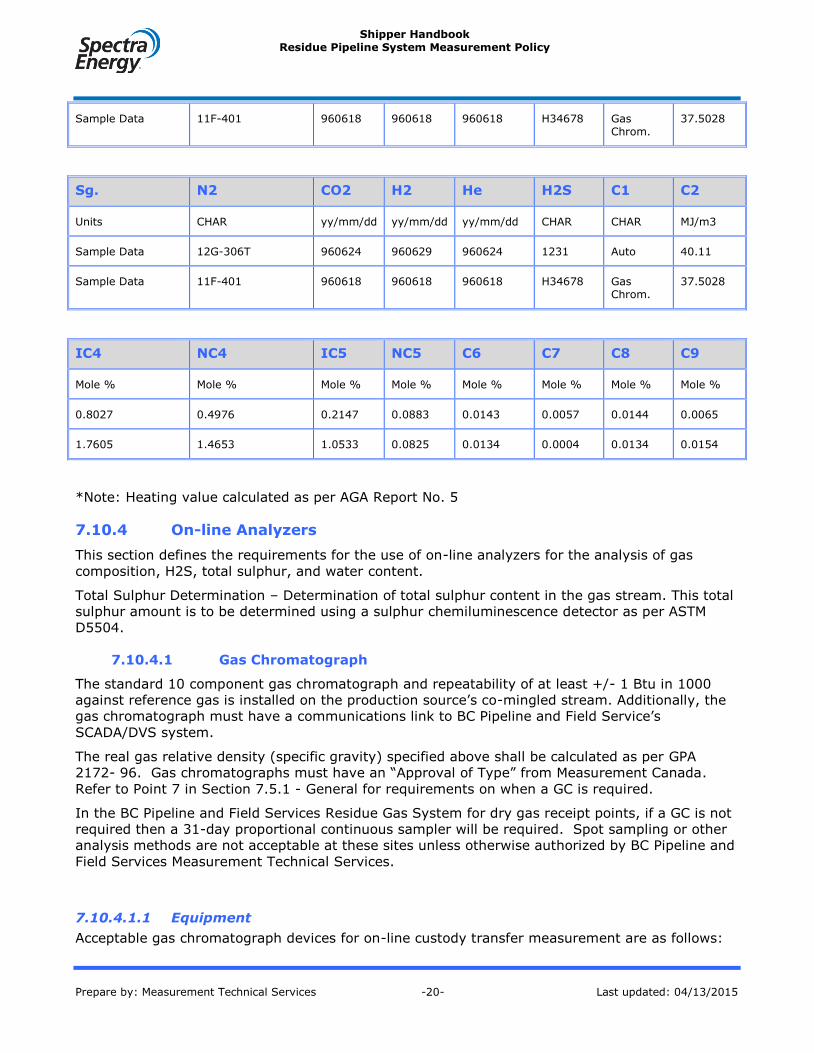
Shipper Handbook Residue Pipeline System Measurement Policy
Prepare by: Measurement Technical Services -20- Last updated: 04/13/2015
Sample Data 11F-401 960618 960618 960618 H34678 Gas Chrom.
37.5028
Sg. N2 CO2 H2 He H2S C1 C2
Units CHAR yy/mm/dd yy/mm/dd yy/mm/dd CHAR CHAR MJ/m3
Sample Data 12G-306T 960624 960629 960624 1231 Auto 40.11
Sample Data 11F-401 960618 960618 960618 H34678 Gas Chrom.
37.5028
IC4 NC4 IC5 NC5 C6 C7 C8 C9
Mole % Mole % Mole % Mole % Mole % Mole % Mole % Mole %
0.8027 0.4976 0.2147 0.0883 0.0143 0.0057 0.0144 0.0065
1.7605 1.4653 1.0533 0.0825 0.0134 0.0004 0.0134 0.0154
*Note: Heating value calculated as per AGA Report No. 5
7.10.4 On-line Analyzers
This section defines the requirements for the use of on-line analyzers for the analysis of gas
composition, H2S, total sulphur, and water content.
Total Sulphur Determination – Determination of total sulphur content in the gas stream. This total
sulphur amount is to be determined using a sulphur chemiluminescence detector as per ASTM
D5504.
7.10.4.1 Gas Chromatograph
The standard 10 component gas chromatograph and repeatability of at least +/- 1 Btu in 1000
against reference gas is installed on the production source’s co-mingled stream. Additionally, the
gas chromatograph must have a communications link to BC Pipeline and Field Service’s
SCADA/DVS system.
The real gas relative density (specific gravity) specified above shall be calculated as per GPA
2172- 96. Gas chromatographs must have an “Approval of Type” from Measurement Canada.
Refer to Point 7 in Section 7.5.1 - General for requirements on when a GC is required.
In the BC Pipeline and Field Services Residue Gas System for dry gas receipt points, if a GC is not
required then a 31-day proportional continuous sampler will be required. Spot sampling or other
analysis methods are not acceptable at these sites unless otherwise authorized by BC Pipeline and
Field Services Measurement Technical Services.
7.10.4.1.1 Equipment
Acceptable gas chromatograph devices for on-line custody transfer measurement are as follows:

Shipper Handbook Residue Pipeline System Measurement Policy
Prepare by: Measurement Technical Services -21- Last updated: 04/13/2015
Daniel Model 570 with 2350 controller using firmware version 1.6. Software version 1.63
is required.
Daniel Model 570 or 590 with 2350 controller using firmware version 1.6. Software version
1.63 is required.
Recommended types of 31-day proportional continuous samplers are as follows:
YZ DynaPak Model DP2000
7.10.4.1.2 GC Sampling Requirements
The sampling system for a gas chromatograph requires a probe that has the sampling probe
located within the center third of the pipe and inserted on the top of the pipe. A liquid shutoff
shall be installed at the start of the sampling line and shall be of the type, Welker Model ALS-1. A
Balston 95S6 coalescing filter using a BX element, followed by a 2 micron Nupro “F” Series
sintered filter, and finally followed by a Genie model 101 membrane filter kit is required. Included
in the sampling system is a snubber and bypass rotometer. The probe and sampling system shall
be installed as per the BC Pipeline and Field Services typical drawing CS - TM - 333.
7.10.4.2 H2S and Total Sulphur Analyzer
Analyzers for monitoring H2S and Total Sulphur are used at dry gas receipt points on the BC
Pipeline and Field Services residue gas transmission system. All dry gas receipts require an H2S
on-line analyzer to be installed. Installations where total sulphurs exceed the BC Pipeline and
Field Services pipeline gas quality specifications, a Total sulphur on-line analyzers shall be
installed.
The sulphur analyzer samples the gas stream on a real time basis and provides a data feed to the
BC Pipeline and Field Services SCADA system using an analog (4-20 mA) signal that represents
the sulphur content in parts per million (ppm). A signal from the H2S analyzer will be used to
close the ESD valve at the receipt point on high H2S, set at 4 ppm. Exceptions to installing a H2S
analyzer may be granted for receipt points where the upstream supply is proven to be sweet and
volume flow rates are less than 283 103M3/day (10 mmscf/day).
7.10.4.2.1 Equipment
Acceptable H2S and total sulphur analyzers for on-line measurement are as follows:
Galvanic Model 801 H2S analyzer.
Galvanic Model 902 Total Sulphur analyzer.
Ametek Model 933 Total Sufphur analyzer
7.10.4.2.2 Sulphur Sampling Requirements
The sampling system for a sulphur analyzers requires a Welker retractable probe (or equivalent)
that has the sampling probe located within the center third of the pipe and inserted on the top of
the pipe. A Balston 95S6 coalescing filter using a BX element, followed by a 2 micron Nupro “F”
Series sintered filter, and finally followed by a Genie model 101 membrane filter kit is required.
7.10.4.3 H20 (Moisture) Analyzers
Analyzers for monitoring water content are required in the BC Pipeline and Field Services residue
gas transmission. Water analyzers are installed in the BC Pipeline and Field Services systems as
follows:
Residue Gas Transmission System:

Shipper Handbook Residue Pipeline System Measurement Policy
Prepare by: Measurement Technical Services -22- Last updated: 04/13/2015
o All dry gas receipt points in BC, and Alberta.
The water analyzer samples the gas stream on a real time basis and provides a data feed to the
BC Pipeline and Field Services SCADA system using an analog (4-20 mA) signal that represents
the water content in pounds per million standard cubic feet (lbs/mmscf). If the water content is
determined to be outside set limits on a consistent basis, the signal from the water analyzer will
be used to close the ESD valve at the receipt point on high H2O (set point at 4 lbs/mmscf).
For systems or at receipt points where an on-line water analyzer is not required, manual dewpoint
checks will be required. Manual dewpoint checks must be taken using a “Bureau of Mines”
approved device; recommended unit is the Chandler Model “B” Dewpoint Tester. Dew point
checks are required to be taken at the same time interval that the receipt point measurement
verification checks are done see Section 7.6 - Procedures for Verification and Calibration of EFM -
Gas Only. All dew point check results shall be reported to BC Pipeline and Field Services as per
Section 7.2.3 -Notification to BC Pipeline and Field Services.
7.10.4.3.1 Equipment
Acceptable water analyzers for on-line measurement are as follows:
Panametrics Moisture Image II – Residue Gas Transmission System only.
Ametek Model 3050 – Residue Gas Transmission System
7.10.4.3.2 H2O Sampling Requirements
The sampling system for a water analyzer requires a Welker retractable probe (or equivalent) that
has the sampling probe located within the center third of the pipe and inserted on the top of the
pipe. A Balston 95S6 coalescing filter using a BQ element followed by a 2 micron Nupro “F” Series
sintered filter is required.
7.10.5 Gas Sampling
7.10.5.1 General
Sampling shall adhere to the following requirements:
Samples must be taken from a fully developed, flowing stream. This will minimize the
possibility of obtaining an unrepresentative sample from a stratified stream.
All sample taps shall be equipped with a quill or sample probe that extends to the center
one third of the pipe. The tap size shall be a minimum of NPS ½ pipe and be equipped with
appropriate valving.
It shall be easy and safe for personnel to gain access to any sample point location.
Platforms with railings shall be provided, as required.
Any automated proportional sampler that is used shall be so designed that it can be
repaired or removed from service without depressurizing the process piping.
Exceptions to installing a H2O analyzer may be granted by BC Pipeline and Field Services for
receipt points where the upstream supply is proven to be Dry gas and volume flow rates are less than 566.8 103M3/day (20 mmscf/day).
Shipper Handbook Residue Pipeline System Measurement Policy
Prepare by: Measurement Technical Services -23- Last updated: 04/13/2015
Permanent instrumentation that indicates the process pressure and where possible, the
process temperature, shall be located near the sampling point.
When a gas chromatograph method is selected, a live serial output from the gas
chromatograph must be fed directly to the receipt point flow computer.
When a gas sampler method is used, it is the Measurement facility operator’s
responsibility to update the receipt point flow computer with the latest gas analysis
7.10.5.1.1 EFM Receipt Points
The Measurement facility operator’s is responsible for determining and updating the gas analysis
used in the flow computer. As per Section 7.1 Gas Measurement, a full gas analysis is required for
the EFM to complete the Detailed analysis AGA 8, 1992 methodology.
The Measurement facility operator’s can determine the receipt point gas analysis in one of the
following ways:
By installing a standard 10 component gas chromatograph repeatability of at least +/- 1
Btu in 1000 against reference gas on the Measurement facility co-mingled stream,
Where the real gas relative density of the production sources behind the receipt point does
not vary by more than +/- 4.0%, installation of a continuous proportional sampler and
have a certified laboratory determine the gas composition as per section 7.10Analysis Data
and Determination recommended for sites that flow under 20 million cubic feet per day.
Utilization of this methodology must be reviewed and approved by Measurement Technical
Services . The results of the previous month’s analysis would be used for the current
month’s volume and energy calculations.
When the gas chromatograph method is selected, a live serial output from the gas chromatograph
must be fed directly to the receipt point flow computer. If the gas sampler method is used, it is
the Measurement facility operator’s responsibility to update the receipt point flow computer with
the latest gas analysis. Pertinent values for the gas composition to C7+ or C10+, depending on the
gathering system of concern, must be loaded into the flow computer.
7.10.5.1.2 Mechanical Chart Based Measurement Facilities
The Measurement facility operator is responsible for determining the gas analysis used when
calculating chart volumes. As per Section 7.1Gas Measurement-, a full gas analysis is to be used
as required for determining AGA 8 detailed method.
The gas analysis is calculated by flow weighting the previous month’s volumes flowing from the
production sources behind the receipt point. The Measurement facility operator must determine
the daily chart volumes based on this monthly flow weighted compositional average of the receipt
point gas. Thus, the gas composition is updated on a monthly basis regardless of the composition
flowing on any particular day.
7.10.5.1.3 Receipt Points With Liquid Metering
This section is not applicable to this policy.
7.10.5.2 Gas Sampling in the Raw Gas Transmission System
This section is not applicable to this policy.
Shipper Handbook Residue Pipeline System Measurement Policy
Prepare by: Measurement Technical Services -24- Last updated: 04/13/2015
7.10.5.2.1 Solution Gas Well Tie-in Points
This section is not applicable to this policy.
7.10.5.2.2 Well Sampling Frequency
This section is not applicable to this policy.
7.10.5.2.3 Manual Gas Spot Samples
This section is not applicable to this policy.
7.10.5.3 Liquid Sampling at Receipt points in the Raw Gas Transmission
System
This section is not applicable to this policy.
7.10.5.3.1 Manual liquid Spot Samples
This section is not applicable to this policy.
7.11 Measurement Data and Reporting
The reports defined in this section are based on the general requirement to provide certain data
as required for custody transfer metering facilities. The reporting requirements for each type of
report are specified in the report section.
7.11.1 Gas Metering Reports
Four types of reports shall be generated based on the measurement data stored in the EFM
device. The reports are as follows:
7.11.1.1 Daily Gas Volume Report
The Daily Gas Volume Report lists all measurement data and variables for a 24 hour period
starting at 07:00 PST each day (Note: this will be based on the gas or contract day). The following
information is to be provided:
meter identification (as assigned by BC Pipeline and Field Services)
hours on production
hourly gas volumes
accumulated daily gas volume
average hourly differential pressure, static pressure and temperature
an indication of flow parameter changes
Supercompressibility calculation method
orifice plate size
line size
contract day
The Daily Gas Volume Report shall be submitted upon request to BC Pipeline and Field Services.
For sites with EFM and communication, the Daily Gas Volume data is brought in through the daily
poll and consequently not required.
Shipper Handbook Residue Pipeline System Measurement Policy
Prepare by: Measurement Technical Services -25- Last updated: 04/13/2015
BC Pipeline and Field Services requires that the Daily Gas Volume Report be submitted by
Electronic File Transfer if requested, see Section 7.11.4.1 - Reports. BC Pipeline and Field
Services has established a standard reporting format for the Daily Gas Volume Report that is
given in Appendix J. The standard report format is provided as an example and BC Pipeline and
Field Services may allow variation of the report format upon written approval.
7.11.1.2 Gas Meter Report
The Gas Meter Report (flow snapshot) lists all information used to calculate a flow volume for each
meter run. The following information is to be provided:
Orifice Meter
meter identification
instantaneous flow rate (Qv)
static pressure (Pf)
differential pressure (hw)
flowing temperature (Tf)
transmitter ranges
line size
orifice size
pressure tap location (upstream/downstream)
atmospheric pressure
orifice plate coefficient of discharge (Cd)
velocity of approach (Ev)
expansion factor (Y)
pipe Reynolds number (ReD)
flowing fluid density (tp)
base fluid density (b)
absolute viscosity ()
compressibility (Z)
isentrophic exponent (k)
base pressure (Pb)
base temperature (Tb)
metric conversion factor
gas analysis and analysis date
relative density
heating value
Positive and Turbine Meter
instantaneous flow rate
flowing pressure (Pf)
Shipper Handbook Residue Pipeline System Measurement Policy
Prepare by: Measurement Technical Services -26- Last updated: 04/13/2015
flowing temperature (Tf)
supercompressibility factor (Fpv)
scaling factor(s) (index)
opening meter reading
closing meter reading
atmospheric pressure
pressure base (Pb)
temperature base (Tb)
relative density
analysis and analysis date
k factor
The Gas Meter Report shall be submitted upon request to BC Pipeline and Field Services or
attached to Form F426 (Inspection Report) whenever any of the flow parameters are changed.
7.11.1.3 Monthly Gas Volume Report
The Monthly Gas Volume Report lists all measurement data for a one month period starting at
07:00 PST on the first of that month. Variables listed for the month are for daily (24 hour) totals
or averages. The following information is to be provided:
meter identification
contract day
daily volumes for each measurement point
daily relative density
average daily differential pressure
average daily static pressure
average daily gas temperature
daily orifice plate size
daily heating value
daily energy (GJ)
hours of flow
line size
monthly maximum day volume
monthly minimum day volume
total daily volume
supercompressibility calculation method
The reporting period is defined as a 24 hour period commencing at the start of the gas day (07:00
PST).

Shipper Handbook Residue Pipeline System Measurement Policy
Prepare by: Measurement Technical Services -27- Last updated: 04/13/2015
Monthly Gas Volume Reports shall be submitted to the BC Pipeline and Field Services Calgary
office as stated in Section 7.2.3 - Notification to BC Pipeline and Field Services.
This report shall contain volume data from 07:00 PST on the first day of the previous month to
the last day of that month. For sites with EFM and communication, the Monthly Gas Volume data
is brought in through the daily poll and consequently not required.
BC Pipeline and Field Services may request that the Monthly Gas Volume Report be submitted to
the BC Pipeline and Field Services Calgary office at a minimum of every 7 days from the first day
of the month. This requirement will be determined based on the measurement impact of that site
to the BC Pipeline and Field Services system.
The EFM device shall be capable of establishing a complete audit trail and report raw data, rates
and volumes on a hourly and daily basis.
BC Pipeline and Field Services requires that the Monthly Gas Volume Report be submitted by
Electronic File Transfer, see Section 7.11.4.1 - Reports. BC Pipeline and Field Services has
established a standard reporting format for the Monthly Gas Volume Report that is given in
Appendix J. The standard report format is provided as an example and BC Pipeline and Field
Services may allow variation of the report format upon written approval.
7.11.2 Liquid Metering Reports
Not applicable to this policy.
7.11.3 Alarm Report
The Alarm Report lists all alarms that have occurred and may have an effect on the measurement
accuracy of the system. The report may be printed as a daily or weekly summary. Each alarm
should be identified as to the type of alarm, date and time of occurrence, and the time of clearing
of the alarm. Certain alarms will be specific to gas measurement and are required for the
following:
internal flow computer failures
communication failures
low power warning
changes to data base
authorized and unauthorized entry into the system
high/low differential pressure static pressure, and temperature
over range values
The Alarm Report shall be submitted to BC Pipeline and Field Services along with the Monthly Gas
Volume Report.
7.11.4 Data Communications
The management of measurement data shall be through the BC Pipeline and Field Services
SCADA/DVS system. The SCADA/DVS is a client server application that uses a Sybase relational
database for data storage. The measurement data collected through EFM device and chart
integration are managed and stored in this system.

Shipper Handbook Residue Pipeline System Measurement Policy
Prepare by: Measurement Technical Services -28- Last updated: 04/13/2015
7.11.4.1 Reports
All reports generated from an EFM facility must be sent to BC Pipeline and Field Services in one of
the following formats, listed in order of preference:
1. Access to a third party database system through remote communication. BC Pipeline and
Field Services shall be given a user access to a remote computer host for the purpose of
electronic transfer of data from one or more EFM facilities. This may require some
development on both ends of the system.
2. The Daily and Monthly Volume Reports may be produced in an Excel 4.0 format (or later
version). The Excel files can then be transferred to BC Pipeline and Field Services by either
3.5 floppy diskette or through electronic mail transfer. The Meter Report and Alarm Report
can be placed on diskette or transferred electronically in the file format defined by the EFM
device.
3. A hardcopy printout of the Daily and Monthly Volume shall be faxed to BC Pipeline and
Field Services Gas Measurement. The Meter Report and Alarm Report can be printed in the
format as defined by the EFM device. This format will only accepted if 1 or 2 cannot be
achieved.
7.12 Measurement Auditing
This section defines the auditing process for measurement data originating from BC Pipeline and
Field Service’s transmission pipeline dry gas receipt points and delivery points.
Spectra Energy Transmission or an independent auditor contracted by Spectra Energy
Transmission will perform internal audits when business circumstances demand it. As per the
General Terms & Conditions, Customers are also able to audit the system or contract an agent to
do so on their behalf. In all cases, corrections to calculated or allocated amounts will be made as
per the policy specified in the Residue Gas and Product Allocations document.
It is the Measurement Volumes Team's responsibility to ensure appropriate follow-up action is
completed in response to any audit and to track and report on the follow-up.
7.12.1 General
The purpose of the auditing process is to ensure that measurement determinations done correctly.
Owners of the any measurement equipment associated with BC Pipeline and Field Service’s
facilities are required to retain pertinent measurement data for a period of two years after the
transaction occurred. BC Pipeline and Field Services reserves the right to audit any measurement
used to determine the transaction volume at anytime during the two-year retention period.
The measurement data to be retained consists of all data and information that is required to verify
hourly and daily quantities, and shall include configuration changes, calibration changes, and
other event changes affecting the operation of the EFM devices. A detailed description of the data
is listed in the appropriate sections below.
Operators of Measurement facilities and or Shippers have access to BC Pipeline and Field Services
data as per the GT&C.
7.12.2 Transmission Pipeline and Dry Gas RP Auditing Process
Defined in the Shipper Handbook.
Shipper Handbook Residue Pipeline System Measurement Policy
Prepare by: Measurement Technical Services -29- Last updated: 04/13/2015
7.13 Ordering of Custody Transfer Equipment
When ordering custody transfer measurement equipment, the following procedures must be
adhered to in order to meet the requirements of this policy.
7.13.1 General
Equipment used for gas custody transfer measurement must meet certain government
requirements over and above all normal requirements such as the approval of the Canadian
Standards Association. These requirements are defined within the Electricity and Gas Act that is
administered through Measurement Canada (MC) The requirements must be met in order for a
device to be legally used for custody transfer measurement.
7.13.2 BC Pipeline and Field Services Badge Number Requirements – Gas
Equipment Only
All custody and non-custody transfer measurement equipment must be tagged and identifiable
with a permanent BC Pipeline and Field Services Badge Number. Badge numbers are assigned
through the Measurement Compliance Specialist position located in Calgary, Alberta. In order to
obtain a Badge Number, the following conditions must be met:
1. BC Pipeline and Field Services Measurement prior to installation and the assignment of a
Badge Number must approve the device.
2. When ordering the measurement equipment, a Badge Number must be obtained before
ordering.
3. All government certificates, fabricator/manufacturer certificates and manufacturer tags
must show the Badge Number that was assigned to that specific piece of equipment.
4. Badge Numbers must be specified on the purchase order.
5. All Government Certificates shall be forwarded to BC Pipeline and Field Services
Measurement in a timely manner as per Section 7.2.3-Notification to BC Pipeline and Field
Services.
Measurement Canada requires a Badge Numbers for registration with them for each piece of
measurement equipment. For gas measurement equipment at a receipt point, a BC Pipeline and
Field Services Badge is not required but a similar permanent tag must be used by the Operator of
the Measurement Facility to register the equipment with Measurement Canada.
7.13.3 Approval of Type, Inspection and Certification
Each piece of equipment used for gas measurement requires an Approval of Type from
Measurement Canada. The Approval of Type declares that Measurement Canada has tested that
measurement equipment and can be used for gas custody transfer measurement. Measurement
Canada will not inspect and verify devices that do not have the Measurement Canada Approval of
Type certification.
Measurement equipment that has Approval of Type must still be inspected in the field or shop and
approved by a Measurement Canada Inspector or an accredited service provider. The MC
Inspector or accredited meter verifier will seal the measurement equipment with a Stamp or Wire
Seal. For measurement devices that Measurement Canada resolve themselves from inspection
under Measurement Canada Bulletin G-14, SET personnel or an approved SET contractor may
conduct these inspections.

Shipper Handbook Residue Pipeline System Measurement Policy
Prepare by: Measurement Technical Services -30- Last updated: 04/13/2015
7.13.4 Gas Measurement Equipment Special Requirements
Any custody transfer equipment used within the BC Pipeline and Field Services System must have
a valid certificate of inspection from Measurement Canada and “Approval of Type” documentation.
Specific requirements related to the various types of measurement equipment used for gas
measurement are defined in the following sections.
7.13.4.1 Orifice Meter Runs
The meter run must be inspected, certified and approved by MC. For new installations, the meter
run is inspected at the manufacturer’s shop prior to shipment. During the meter run inspection,
the measurement of the inside diameter (ID) of the meter run will be completed by the
manufacturer, witnessed by MC, and then stamped on the permanent meter run tag.
The certificate of compliance report for the meter run shall include the following:
Orifice fitting concentricity verification report
Orifice meter tube/fitting calibration record
Material certification/Inspection Report
Surface roughness report (optional)
Differential pressure tap hole location report
Mill test inspection certificates
Radio graphic inspection report
The certificate of compliance along with a facsimile of the manufacturer’s nameplate located on
the meter run and a progression sheet (travel sheet) shall be forwarded to BC Pipeline and Field
Services. Orifice meter runs must be hydrostatic tested and the chart recording of the test
provided to BC Pipeline and Field Services.
All orifice plates used with custody transfer approved orifice meters must be inspected, certified
and stamped by Measurement Canada or an accredited meter verifier.
7.13.4.2 Turbine Meters
Turbine meters used in high pressure gas applications require a high pressure calibration test to
be completed at time of certification of the meter. Typically, the high pressure calibration is
completed at the average operating pressure that the meter will be measuring at. In most cases,
BC Pipeline and Field Services specifies a five (5) point high pressure calibration at 5200 kPa (750
psig). The following facilities are acceptable for turbine meter calibration and proving:
1. KTI Ltd. Ontario, Canada
2. Colorado Experimental Engineering Station Inc. (C.E.E.S.I.)
3. Nederlands Meetinstituut (N.M.I.)
4. TransCanada Calibrations Ltd. (TCC) facility by Winnipeg, Manitoba , Canada
5. Invensys Energy Metering facility at Du Bois, Pennsylvania, USA
7.13.4.3 Ultrasonic Meters
Ultrasonic meters used in high pressure gas applications require a high pressure calibration test to
be completed at time of certification of the meter. Typically, the high pressure calibration is
completed at the average operating pressure that the meter will be measuring at. The following
facilities are acceptable for ultrasonic meter calibration and proving:

Shipper Handbook Residue Pipeline System Measurement Policy
Prepare by: Measurement Technical Services -31- Last updated: 04/13/2015
1. Nederland’s Meetinstituut (N.M.I.).
2. Ruhrgas Pigsar calibration facility, Germany.
3. CEESI High Flow Test Facility, Garner, Iowa USA.
4. TransCancada Calibrations Facility, Winnipeg, Manitoba.
7.13.4.4 Mass Flow Meters
Mass flow meters used in high pressure gas applications require a high pressure calibration test to
be completed at time of certification of the meter. Typically, the high pressure calibration is
completed at the average operating pressure that the meter will be measuring at.. The meters
shall be tested to the following test points; 10,25,50,75, and 100 percent of maximum in-service
flow rate The following facilities are acceptable for ultrasonic meter calibration and proving:
1. Colorado Experimental Engineering Station Inc. (C.E.E.S.I.)
7.13.4.5 Rotary and Diaphragm Meters
This meters used in high pressure gas applications require only atmospheric testing , by an
accredited meter verifier. BC Pipeline and Field Services specifies as found and as left test. The
following facilities are acceptable for Rotary and Diaphragm meter calibration and proving:
1. BC Gas
7.13.4.6 Measurement Canada Sealing Period
The sealing period for custody transfer equipment is provided in the following table. These sealing
periods are presented as per the Electricity and Gas Act and are summarized in the following
table.
For devices such as transmitters, the seal may have to be broken to calibrate the device in the
field. In any case where a seal is broken or removed to work on the custody transfer equipment,
Measurement Canada must be informed that the seal has been broken or removed. Measurement
Canada may re-inspect and seal the device at that time or at their earliest convenience.
Custody Transfer Equipment Measurement Canada Sealing Period
(Years)
Orifice Fitting and associated meter tube 6
Turbine Meter 6
Rotary Meter – Body 20
Rotary Meter with TC element 6
Diaphragm Meter 6
Ultrasonic Meter 6
Mass Flow Meters 6

Shipper Handbook Residue Pipeline System Measurement Policy
Prepare by: Measurement Technical Services -32- Last updated: 04/13/2015
Mechanical Chart Recorder 6
Electronic Flow Measurement Device 6
Transmitters 7
Gas Chromatograph 1
7.14 Downstream Taps
This section deals with taps that are located downstream of a custody transfer metering Receipt
point. Downstream taps are categorized based on the BC Pipeline and Field Services system they
reside in, as follows:
Residue Gas Transmission System (includes Dry Gas Receipt Points)
7.14.1 BC Pipeline and Field Services Residue Gas Transmission Downstream
Taps
The residue gas transmission system consists of all delivery points and dry gas receipt points on
the BC Pipeline and Field Services system.
For the BC Pipeline and Field Services residue gas transmission system, any downstream tap from
a Receipt point must be measured using custody transfer approved metering. All Upstream taps
of a delivery metering point off of the BC Pipeline and Field Services Pipeline shall also be
metered. In no instance is it acceptable to have a downstream tap without proper measurement.
See Section 7.1 - Measurement Policy
Gas Measurement for further details. Gas Measurement Facility Requirements
7.14.1.1 Bi-Directional and Interconnecting metering Facilities
In all cases, the primary metering that is in place at the receipt point or delivery point must
comply with this Policy. BC Pipeline and Field Services may accept the primary measurement at a
receipt point that is used to produce gas to a non-BC Pipeline and Field Services Pipeline
Transmission system. The sales gas metering must be inspected and approved by Measurement
Canada. BC Pipeline and Field Services will also require the right to witness any calibration,
verification, and other inspection of these facilities.
7.14.2 Raw Gas Transmission Downstream Taps
Not applicable to this policy.
7.14.3 Exception Measurement Facilities Requirements (RGT)
Not applicable to this policy.
7.14.3.1 Verification and Calibration of Measurement Equipment
EFM (or chart) equipment installed as part of the Downstream Tap Exception Rule shall be
maintained in a manner that meets custody transfer requirements for that device. An EFM device
shall be verified or calibrated as per the BC Pipeline and Field Services Measurement Policy with
the exception to schedule, as follows:
Shipper Handbook Residue Pipeline System Measurement Policy
Prepare by: Measurement Technical Services -33- Last updated: 04/13/2015
1. BC Pipeline and Field Services shall inspect the EFM device as part of the initial turn-on and
prior to production on or delivery off of the BC Pipeline and Field Services system
commencing.
2. The Operator of the Measurement Facility shall verify the EFM device within one month
prior to any production coming on or delivery off of the BC Pipeline and Field Services
system. If the verification is outside the limits defined in the Measurement Policy, the EFM
device must calibrate.
Note: A verification or calibration need only be completed prior to production
commencing.
3. BC Pipeline and Field Services has the right to witness any verification or calibration that is
performed on the EFM or associated metering equipment as stated in Section 7.6.1-
Procedures for Verification and Calibration of EFM - Gas Only.
7.15 Tap Application
This section defines the requirements for applying for a tap to a BC Pipeline and Field Services
system.
7.15.1 Operator of the Measurement Facility or Customers Responsibilities
An Operator of the Measurement Facility wishing to connect to the BC Pipeline and Field Services
Dry Gas Transmission System should ensure that the following documents and information is
supplied to BC Pipeline and Field Services prior to construction of facilities to ensure that undue
delays and/or unnecessary costs are avoided.
7.15.1.1 Information Requirements to be Fulfilled Prior to Construction
The following requirements are to be fulfilled prior to construction:
1. The Operator of the Measurement Facility or Customer should contact the Tap Application
Coordinator, Fifth Ave Place, East Tower, 425 1st Street S.W., Calgary, AB, T2P 3L8, with
regard to the proposed connection and then complete and return an "Application For Tap" -
BC Pipeline and Field Services Form F273. The Operator of the Measurement Facility
should ensure that all pertinent information that may have a bearing on the application is
included. The Operator of the Measurement Facility should also note that the location of
the meter station is subject to approval by BC Pipeline and Field Services as set out in the
requirements below. Year round site access is a requirement. In some instances, BC
Pipeline and Field Services may require that a Operator of the Measurement Facility tie into
an existing tap being used by another Operator of the Measurement Facility, etc.. The Tap
Application Coordinator will, in consultation with BC Pipeline and Field Services Field
Services and the Lands and Right-of-Way Department, contact the Operator of the
Measurement Facility or Customer as to the approved location for the tap.
2. Operator of the Measurement Facilities or Customer shall do their best to give BC Pipeline
and Field Services as much notice as possible to allow BC Pipeline and Field Services to
properly plan and execute any work required. The minimum time to complete installation
of field facilities will depend on the type of tap required and facilities required. The general
rule of thumb is at least two (2) months notice for installation of a simple tap and up to six
(6) months if additional facilities are required such as on-line water content measurement
and/or telemetry.
3. The Operator of the Measurement Facility or Customer, at this stage or before, should
contact the appropriate (i.e., Fort Nelson, Pine River, etc.) Field Service’s Area Manager to

Shipper Handbook Residue Pipeline System Measurement Policy
Prepare by: Measurement Technical Services -34- Last updated: 04/13/2015
discuss the routing and connection of the Operator of the Measurement Facility's line to the
tap on the BC Pipeline and Field Services system.
4. The Operator of the Measurement Facility's or Customer’s local representative should keep
the appropriate Field Services office aware of their progress with regard to line laying, etc.
so that BC Pipeline and Field Services can ensure that the installation of the tap meets any
time restrictions.
5. The Operator of the Measurement Facility or Customer shall provide to BC Pipeline and
Field Services, as early as practicable and in any event prior to construction, a detailed site
plan as well as a piping plan and isometric showing any flaring, pigging facilities etc. to be
located adjacent to the BC Pipeline and Field Services pipeline, the proposed installation
and equipment. These drawings will be reviewed by the Measurement Department and
others to ensure compliance with requirements as set out below. BC Pipeline and Field
Services must review all measurement facility designs prior to construction.
7.15.1.2 Design Requirements – Receipt or Customer Delivery Facilities
The Operator of the Measurement Facility are required to ensure all their facilities comply with BC
Pipeline and Field Services requirements and this Policy. Failure to meet these requirements may
result in a delay in issuance of the "Turn-On" order.
1. The location of the custody transfer metering facility shall be located next to BC Pipeline
and Field Service’s right-of-way (ROW) unless otherwise approved by BC Pipeline and Field
Services. The Operator of the Measurement Facility shall provide justification for locating
the custody transfer metering facility other than next to the BC Pipeline and Field Services
ROW. If the custody transfer metering facility is located away from the BC Pipeline and
Field Services ROW, a Lost Gas Indemnity Agreement shall be required.
2. The Operator of the Measurement Facility shall install an anchor flange and ring plate set
into a concrete anchor block on his pipeline no farther than 15 m (50 ft.) upstream of the
tie-in point at the BC Pipeline and Field Services right-of-way. The dimensions of this
anchor block are to be determined by the size of the pipeline, as set out in the table below:
88.9 mm pipe o.d. 1.2 m x 1.2 m x 0.6 m
114.3 mm pipe o.d. 1.2 m x 1.2 m x 0.6 m
168.3 mm pipe o.d. 1.5 m x 1.5 m x 0.9 m
219.1 mm pipe o.d. 2.0 m x 2.0 m x 0.9 m
3. The following information must be submitted to the Team Leader, Measurement Technical
Services:
a. Valid IC certificate of inspection of the meter run and fitting.
b. Valid IC orifice meter tube inspection report.
c. Actual elevation of the meter station (feet) obtained from either a topographical map or
a survey certificate of the wellhead or pipeline right-of-way.
d. The name, phone number, fax number and address of the Operator of the
Measurement Facility or contractor.
4. Whenever possible the following information should be provided as included in the
manufacturer’s data book for orifice fitting:
a. Certificate of compliance report, including:
differential pressure tap hole location report,

Shipper Handbook Residue Pipeline System Measurement Policy
Prepare by: Measurement Technical Services -35- Last updated: 04/13/2015
orifice plate sealing device leak test report,
mill test inspection certificates,
radiographic inspection report.
b. Facsimile of manufacturers name plate of meter run.
c. Manufacturer’s progression sheet.
5. BC Pipeline and Field Services may require that a Bureau of Mines dewpoint tester be
available at the receipt point facility. A 1/2" tap complete with a midline probe must be
installed downstream of the meter run internal to the building for gas quality
measurements.
6. A sampling point is required as defined in Section 7.10- Analysis Data and Determination.
7. The metering facility shall be properly housed and heated to enable proper operation and
maintenance.
8. For Receipt point metering facilities returned gas for fuel, blow downs, etc. is to be taken
from the upstream side of the custody transfer meter. Any gas taken from the
downstream side of the custody transfer meter must be metered separately. Existing
downstream taps that are not metered shall be plugged if the tap size is of a diameter of
1” or smaller and plugged and welded if the diameter is greater than 1”, unless BC Pipeline
and Field Services agrees otherwise.
9. For Delivery point metering facilities all gas for fuel, blow downs, etc. is to be taken from
the downstream side of the custody transfer meter. Any gas taken from the upstream side
of the custody transfer meter must be metered separately. Existing upstream taps that
are not metered shall be plugged unless BC Pipeline and Field Services agrees otherwise.
10. All production tied to the BC Pipeline and Field Services system must provide high
shutdown pressure controls, in the Operator’s facilities, to ensure that the production is not
delivered at any time to BC Pipeline and Field Service’s system in excess of the maximum
pressure detailed in the GT&C. Please note that this maximum pressure is also the
maximum operating pressure for BC Pipeline and Field Service’s pipeline.
11. All Delivery point metering systems tied to the BC Pipeline and Field Services system must
provide high shutdown pressure controls and pressure relief’s, in the Operator’s facilities,
to ensure that the delivered gas from BC Pipeline and Field Service’s system is not in
excess of the maximum pressure required by the operator’s facilities.
12. Operators should note that their facilities will be subject to a final inspection by BC Pipeline
and Field Services Field Measurement personnel to ensure compliance with this Policy prior
to the issuance of the "Turn-On" order.

Shipper Handbook Residue Pipeline System Measurement Policy
Prepare by: Measurement Technical Services -A- Last updated: 04/13/2015
Appendix A – Measurement Forms
List of Forms:
1. F41 – Orifice Plate Change
2. F426 – EFM Inspection Report
3. F127 – Liquid Meter Inspection Report
4. F125 – Micrometer Test Work Sheet
5. F46 – Orifice Measurement Equipment Record
6. F66 – Orifice Meter Run Installation Report
7. F71 – Positive Meter Installation Report
8. F99 – Chromatograph Inspection Report
9. F98- Measurement Equipment and Process Tracker Form
All Forms are available from Spectra Energy Transmission Canada; please refer to Section 7.2.3
Notification to BC Pipeline and Field Services for contact information.
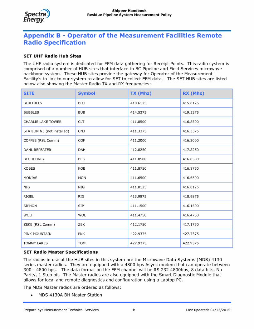
Shipper Handbook Residue Pipeline System Measurement Policy
Prepare by: Measurement Technical Services -B- Last updated: 04/13/2015
Appendix B - Operator of the Measurement Facilities Remote Radio Specification
SET UHF Radio Hub Sites
The UHF radio system is dedicated for EFM data gathering for Receipt Points. This radio system is
comprised of a number of HUB sites that interface to BC Pipeline and Field Services microwave
backbone system. These HUB sites provide the gateway for Operator of the Measurement
Facility’s to link to our system to allow for SET to collect EFM data. The SET HUB sites are listed
below also showing the Master Radio TX and RX frequencies:
SITE Symbol TX (Mhz) RX (Mhz)
BLUEHILLS BLU 410.6125 415.6125
BUBBLES BUB 414.5375 419.5375
CHARLIE LAKE TOWER CLT 411.8500 416.8500
STATION N3 (not installed) CN3 411.3375 416.3375
COFFEE (RSL Comm) COF 411.2000 416.2000
DAHL REPEATER DAH 412.8250 417.8250
BEG JEDNEY BEG 411.8500 416.8500
KOBES KOB 411.8750 416.8750
MONIAS MON 411.6500 416.6500
NIG NIG 411.0125 416.0125
RIGEL RIG 413.9875 418.9875
SIPHON SIP 411.1500 416.1500
WOLF WOL 411.4750 416.4750
ZEKE (RSL Comm) ZEK 412.1750 417.1750
PINK MOUNTAIN PNK 422.9375 427.7375
TOMMY LAKES TOM 427.9375 422.9375
SET Radio Master Specifications
The radios in use at the HUB sites in this system are the Microwave Data Systems (MDS) 4130
series master radios. They are equipped with a 4800 bps Async modem that can operate between
300 - 4800 bps. The data format on the EFM channel will be RS 232 4800bps, 8 data bits, No
Parity, 1 Stop bit. The Master radios are also equipped with the Smart Diagnostic Module that
allows for local and remote diagnostics and configuration using a Laptop PC.
The MDS Master radios are ordered as follows:
MDS 4130A BH Master Station

Shipper Handbook Residue Pipeline System Measurement Policy
Prepare by: Measurement Technical Services -B- Last updated: 04/13/2015
Hot Standby Operation
Full Duplex Operation
5 Watt (+37dBm) Power Output
24 VDC Input Power
19” Rackmount
Equipped with Smart Diagnostic Module
Equipped with 4800 bps Asynchronous RS 232 Digital Interface Modem
406 - 430 Mhz Band Operation
TX Freq: (specify operating frequency)
RX Freq: (specify operating frequency)
A more detailed breakdown of the MDS 4130 Master Radio follows:
Manufacturer: Microwave Data Systems (MDS)
Model: 4130A-B-H-2-A-1-5-J-7-1-3
4130A Radio Series
B Base Station
H Hot Standby
2 24 VDC Input Power
A 4800 bps Async RS232 Digital Interface Modem (DCE)
p/n 03-1286A11 (300 - 4800 bps operating range)
1 12.5 kHz Bandwidth
5 5 - 10 Mhz Separation
J 406 - 430 Mhz RX Frequency Range
7 406 - 425 Mhz TX Frequency Range
1 Local / Remote Diagnostics
3 DOC RSS-122 Canadian Certification
Operator of the Measurement Facility Remote Radio Specification
There are two types of remote radios that can be used to link into the MDS 4130 Master radios.
The original remote radio is the MDS 4310A Smart Transceiver. This is described in section 7.3.1.
MDS has introduced a new generation of Master and Remote radios. These are the MDS 47xx
series of radios. Their model MDS 4710B Remote is backward compatible and will work with the
MDS 4130 Master radios. This radio is described in section 7.3.1.
MDS 4310a Series Remote Transceiver
The following are details on the MDS 4310A remote radio. The options indicated are additional PC
boards that the radio must be equipped with.
Manufacturer: Adaptive Broadband

Shipper Handbook Residue Pipeline System Measurement Policy
Prepare by: Measurement Technical Services -B- Last updated: 04/13/2015
Microwave Data Systems (MDS) Division
Model: MDS 4310A Remote Transceiver (Half Duplex)
Frequency Band: 406 - 430 Mhz
Options: P/N 03-1958A01 Remote Maintenance Module Card
P/N 03-1831A01 4800 bps Asynchronous RS 232 Digital Interface Modem Card
Part Number Decoding:
P/N: 4310-RA-1-B-1-5-J-4-3-C-A
4310 Radio Series
RA Remote Radio
1 12 VDC Primary Power
B 4800 bps Async RS232 Digital Interface
p/n 03-1831A01 (300 - 4800 bps operating range)
1 12.5 kHz Bandwidth
5 5 - 10 Mhz Separation
J 406 - 430 Mhz Frequency Range
4 Remote Maintenance Diagnostics Module
p/n 03-1958A01
3 I.C. RSS - 122 Canadian Certification
C CSA Safety Certification
A
TX Freq: (specify operating frequency) *
RX Freq: (specify operating frequency) *
* The Remote radio TX and RX frequencies will be opposite to the Master TX and RX frequencies
listed in Point 1 - SET UHF Radio Hub Sites.
Example: The TX and RX frequencies for a Remote radio, which must link
to the BLUEHILLS Master radio, are:
TX: 415.6125 Mhz
RX: 410.6125 Mhz
MDS 4710B Series Remote Radio
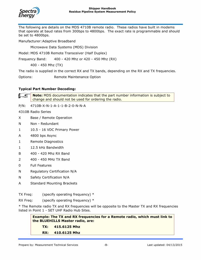
Shipper Handbook Residue Pipeline System Measurement Policy
Prepare by: Measurement Technical Services -B- Last updated: 04/13/2015
The following are details on the MDS 4710B remote radio. These radios have built in modems
that operate at baud rates from 300bps to 4800bps. The exact rate is programmable and should
be set to 4800bps.
Manufacturer: Adaptive Broadband
Microwave Data Systems (MDS) Division
Model: MDS 4710B Remote Transceiver (Half Duplex)
Frequency Band: 400 - 420 Mhz or 420 - 450 Mhz (RX)
400 - 450 Mhz (TX)
The radio is supplied in the correct RX and TX bands, depending on the RX and TX frequencies.
Options: Remote Maintenance Option
Typical Part Number Decoding:
Note: MDS documentation indicates that the part number information is subject to
change and should not be used for ordering the radio.
P/N: 4710B-X-N-1-A-1-1-B-2-0-N-N-A
4310B Radio Series
X Base / Remote Operation
N Non - Redundant
1 10.5 - 16 VDC Primary Power
A 4800 bps Async
1 Remote Diagnostics
1 12.5 kHz Bandwidth
B 400 - 420 Mhz RX Band
2 400 - 450 MHz TX Band
0 Full Features
N Regulatory Certification N/A
N Safety Certification N/A
A Standard Mounting Brackets
TX Freq: (specify operating frequency) *
RX Freq: (specify operating frequency) *
* The Remote radio TX and RX frequencies will be opposite to the Master TX and RX frequencies
listed in Point 1 - SET UHF Radio Hub Sites.
Example: The TX and RX frequencies for a Remote radio, which must link to
the BLUEHILLS Master radio, are:
TX: 415.6125 Mhz
RX: 410.6125 Mhz
Shipper Handbook Residue Pipeline System Measurement Policy
Prepare by: Measurement Technical Services -B- Last updated: 04/13/2015
The MDS 4310A and MDS 4710B radios only come with a nominal 12VDC input power
requirement. MDS can also supply the above radios in a NEMA 4 packaged system suitable for
outdoor mounting with various AC and DC input power supplies. More details on these packaged
systems can be obtained from MDS or their local distributors.
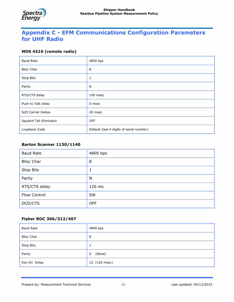
Shipper Handbook Residue Pipeline System Measurement Policy
Prepare by: Measurement Technical Services -C- Last updated: 04/13/2015
Appendix C - EFM Communications Configuration Parameters for UHF Radio
MDS 4310 (remote radio)
Baud Rate 4800 bps
Bits/ Char 8
Stop Bits 1
Parity N
RTS/CTS delay 100 msec
Push to Talk delay 0 msec
Soft Carrier DeKey 20 msec
Squelch Tail Eliminator OFF
Loopback Code Default (last 4 digits of serial number)
Barton Scanner 1130/1140
Baud Rate 4800 bps
Bits/ Char 8
Stop Bits 1
Parity N
RTS/CTS delay 120 ms
Flow Control SW
DCD/CTS OFF
Fisher ROC 306/312/407
Baud Rate 4800 bps
Bits/ Char 8
Stop Bits 1
Parity 0 (None)
Key On Delay 12 (120 msec)
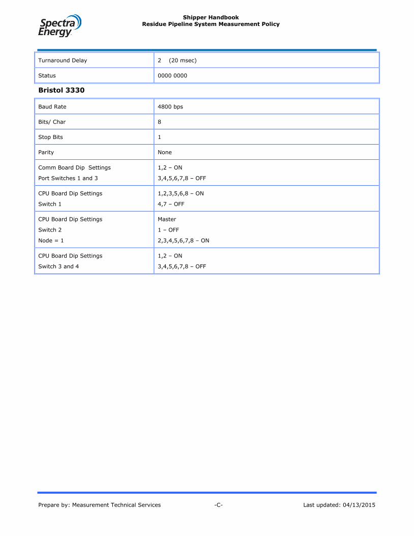
Shipper Handbook Residue Pipeline System Measurement Policy
Prepare by: Measurement Technical Services -C- Last updated: 04/13/2015
Turnaround Delay 2 (20 msec)
Status 0000 0000
Bristol 3330
Baud Rate 4800 bps
Bits/ Char 8
Stop Bits 1
Parity None
Comm Board Dip Settings
Port Switches 1 and 3
1,2 – ON
3,4,5,6,7,8 – OFF
CPU Board Dip Settings
Switch 1
1,2,3,5,6,8 – ON
4,7 – OFF
CPU Board Dip Settings
Switch 2
Node = 1
Master
1 – OFF
2,3,4,5,6,7,8 – ON
CPU Board Dip Settings
Switch 3 and 4
1,2 – ON
3,4,5,6,7,8 – OFF

Shipper Handbook Residue Pipeline System Measurement Policy
Prepare by: Measurement Technical Services -D- Last updated: 04/13/2015
Appendix D - EFM Communications Configuration Parameters for Dial-up
Barton Scanner 1130/1140
Baud Rate 1200 – 9600 bps
Bits/ Char 8
Stop Bits 1
Parity N
RTS/CTS delay 0 msec
Flow Control SW
DCD/CTS OFF
Baud Rate 1200 – 9600 bps
Fisher ROC 306/312/407
Baud Rate 1200 – 9600 bps
Bits/ Char 8
Stop Bits 1
Parity 0 (None)
Key On Delay 1 (20 msec)
Turnaround Delay 1 (10 msec)
Status 0000 0000
Mode 0000 0000
Bristol 3330
Baud Rate 1200 - 9600 bps
Bits/ Char 8
Stop Bits 1
Parity None
Comm Board Dip Settings
Port Switches 1 and 3
1,2,7,8 – ON
3,4,5,6 – OFF

Shipper Handbook Residue Pipeline System Measurement Policy
Prepare by: Measurement Technical Services -D- Last updated: 04/13/2015
CPU Board Dip Settings
Switch 1
1,2,3,5,6,8 – ON
4,7 – OFF
CPU Board Dip Settings
Switch 2
Node = 1
Master
1 – OFF
2,3,4,5,6,7,8 – ON
CPU Board Dip Settings
Switch 3 and 4
1,2,7,8 – ON
3,4,5,6 – OFF

Shipper Handbook Residue Pipeline System Measurement Policy
Prepared by: Measurement Technical Services -D- Last updated: 03/26/2015
Appendix E - Examples of Calibration Equipment
The test equipment listed below is equipment that has been recognized as meeting the
requirements of Section 7.6.4 of this policy as of July 5, 2001. This list is not intended to preclude
other acceptable devices but is simply a list of examples of acceptable equipment.
Test Equipment Make/Model
Differential Pressure Testers Ametek – Model PK 254 WCF SS
Static Pressure Testers Druck – Model DPI 610
Ametek 4004P
Temperature Testers Barnant RTD Thermometer Model 600-9340
Multi-function Calibrators Druck/Unomat – Model MCX
Promac – Model DHT 830
Process Calibrators Fluke – Series 740
Personal Gas Detectors Industrial Scientific – Model LTX 310 (H2S – CO – LEL)
Industrial Scientific – Model TMX 412 (H2S – CO – LEL)
Drager – Model 190 (H2S)
Multi-meters Fluke – Model 8060A
Fluke – Model 87
Transmitter Communicator Hart – Model 275
Oscilloscope Fluke – Model 99 Scope Meter
Dewpoint Analyzer Chandler – Model B
Turbine Meter Prover Equimeter Auto Adjust Turbo Meter Field Prover

Shipper Handbook Residue Pipeline System Measurement Policy
Prepared by: Measurement Technical Services -F- Last updated: 03/26/2015
Appendix H - Checklist for Natural Gas Spot Sampling
HYDROCARBON SAMPLING INTO CYLINDERS - The checklist below provides notes and
recommendations that should be followed when obtaining natural gas samples in single chamber,
double valve cylinders using the Evacuated Container and Purge Methods or in floating piston
cylinders using the Floating Piston Cylinder Method. The use of single chamber, double valve
cylinders is the norm for natural gas spot sampling and the aforementioned methods are BC
Pipeline and Field Service’s preferred single chamber cylinder methods. However, the use of
floating piston cylinders is also acceptable. The actual procedures followed should be based on
GPA Standard 2166, latest revision, Obtaining Natural Gas Samples for Analysis by Gas
Chromatography.
The site configuration and equipment used should meet all the requirements specified in
Sections 7.10.5.1, 7.10.5.2, and 7.10.5.2.4 of this Policy.
The sampling area is to be free of any potential ignition sources.
Personnel involved with the sampling must always wear breathing air apparatus when
purging sour gas to the atmosphere and must observe sour gas safety procedures, as
appropriate.
The sampling point should be identified with a permanent tag to ensure the best location is
always used for analysis purposes.
Ensure that all components used in the sampling assembly are appropriately rated for the
system pressure and temperature, are made of components compatible with the process
stream, and are in a state of good repair. Note that plastic, rubber, copper or brass
containing components are not acceptable. The sampling assembly must include a
minimum of one pressure gauge, depending on which sampling method is used. Ensure all
sample cylinders are stamped DOT Approved.
Appropriate sample conditioning shall be used if liquid or contaminant carry-over from the
gas stream is suspected. Separators must be used cautiously to ensure normal heavy
ends do not condense out.
Minimize the distance between the sample point and the sample cylinder. No longer than 1
meter is recommended.
Vented sour gas can be bubbled through a solution of sodium hydroxide to remove H2S.
Ensure gas being bled or vented to atmosphere does not impinge on gravel or any area
where sparking could occur.
The sample cylinder should be orientated such that its inlet connection is at the bottom.
This will help prevent any liquids from entering the cylinder.
It is good practice to slope the sampling assembly tubing back into the process to drain
liquids away from the sample container. There should be no sags or dips in the line.
If a sampling hose is used and streams of varying composition are being sampled, sample
the leaner streams first. Ensure hoses have not been previously used to obtain liquid
samples.
If sampling from a new well or new piping, flow for sufficient time to allow the pipe walls
and stream components to reach equilibrium.
When using the Purge and Fill Method, avoid conditions that would cause the sample
cylinder to be at a temperature colder than the process stream. Any subsequent liquid

Shipper Handbook Residue Pipeline System Measurement Policy
Prepared by: Measurement Technical Services -F- Last updated: 03/26/2015
drop-out will result in a non-representative sample. If appropriate to take precautions
against liquid drop-out and if the sampling assembly is rated for the sampling pressure at
the elevated temperature, heat the sampling assembly in a safe manner to a temperature
greater than the source temperature.
As a precaution against accidental loss, duplicate samples are recommended for all
sampling and especially for a site that is difficult to resample. The second sample would be
analyzed in cases where the primary sample is suspect.
Sample cylinder valves should be closed finger tight only; the soft seats on these valves
can be damaged if they are tightened with a wrench.
After a sample has been obtained, install the cylinder plug bolts and perform a leak check
on all connections. A leak test can be performed by submerging the cylinder in water or
applying a soap solution such as Snoop to all connections.
Note that the “As Sampled Pressure” shall be recorded and forwarded with the sample to
the laboratory. The “As Sampled Temperature” shall be recorded and forwarded as well if
available.
Ensure the cylinder is tagged appropriately with all required information and complete and
forward any necessary BC Pipeline and Field Services forms. If shipping by carrier, the
cylinder valves must be protected by capping or crating the cylinder in a strong and safe
manner.
SOUR GAS SAMPLING OF LOW CONCENTRATIONS – BC Pipeline and Field Service’s policy is to
use Tedlar bags to obtain samples of gas streams that are to be analyzed for sulphur compounds
where the H2S content in the gas stream is 2100 mg/m3 (1500 ppm) or less. These samples are
to be obtained using the Purge and Fill Method. All aspects of the HYDROCARBON SAMPLING
checklist shown above apply to SOUR GAS SAMPLING with Tedlar bags except those practices
related to the sample cylinder itself. Other requirements are listed below.
The Tedlar bag need only be filled and purged once before obtaining the sample. The bag
is never to be filled beyond 80 to 90% of its capacity. (Expansion space is required.)
Cease stream sampling if water slugging is occurring. Water slugging in a sour gas well
can cause hydrogen sulphide to vary from its actual value to nothing.
The Tedlar bag must be shipped in an opaque container and, as per Section 7.10.2.2 of
this Policy, the contents must be analyzed as soon as possible but in any case within 72
hours of obtaining the sample. Time is of the essence.
The Tedlar bag must be kept away from sources of light and heat as the contents are very
reactive. Sources of energy will cause the internal contents to react and degrade such that
the subsequent test results will be non-representative of the gas stream.
SOUR GAS SAMPLING OF HIGH CONCENTRATIONS - Where the H2S content of the gas stream is
in excess of 2100 mg/m3, a Tutweiler test can be used to determine the H2S content. However,
obtaining a Tedlar bag sample for gas chromatography analysis is still acceptable in these
conditions.
Shipper Handbook Residue Pipeline System Measurement Policy
Prepared by: Measurement Technical Services -G- Last updated: 03/26/2015
Appendix I - Measurement Report Examples
List of Reports:
1. Daily Gas Volume Report
2. Gas Meter Report
3. Monthly Gas Volume Report
4. Alarm Report

Shipper Handbook Residue Pipeline System Measurement Policy
Prepared by: Measurement Technical Services -H- Last updated: 03/26/2015
Appendix J – References
Report Number Report Title
AGA Report No. 3 4 th edition, 2000
(API Chapter 14.3)
Orifice Metering of Natural Gas and Other Related
Hydrocarbon Fluids (references to Part 1, 2, 3 and 4)
AGA Part No. 4 Gas Measurement Manual - Gas Turbine Metering
AGA Report No. 5 Fuel Gas Energy Metering
AGA Report No. 7 Measurement Of Gas By Turbine Meters
AGA Report No. 8 Compressibility Factors of Natural Gas and Other Related Hydrocarbon Gases
AGA Report No. 9 Measurement of Gas by Multi-path Ultrasonic Meters
ASTM D5504 Standard Test Method for Determination of Sulfur Compounds in Natural Gas and Gaseous Fuels by Gas Chromatography and Chemiluminescence
GPA 2145 Table of Physical Constants of Paraffin Hydrocarbons
and Other Components of Natural Gas
GPA Method 2172-96 Calculation of Gross Heating Value, Relative Density, and Compressibility Factor for Natural Gas Mixtures from Compositional Analysis
GPA Method 2265 Analysis of Natural Gas Mixtures by Gas Chromatography
GPA Method 2377 Test for Hydrocarbon Sulfide and Carbon Dioxide in Natural Gas Using Length of Stain Tubes
Section 14.180 Oil and Gas Conservation Regulations of Alberta
Section 79 Petroleum and Natural Gas Act of British Columbia

Shipper Handbook Residue Pipeline System Measurement Policy
Prepared by: Measurement Technical Services -42- Last updated: 03/26/2015
Appendix K - Orifice Meter run and plate Inspection and Testing Requirements.
Purpose: To replace MC inspection services with Manufacturer or machine shop inspections.
Scope:
SET requests a copy of each manufacturer test procedure for orifice meter runs and plates to comply with
AGA Report #3 Fourth Edition Part 2 for orifice metering. All Meters and flow conditioners must be
approved devices under the Measurement Canada requirements and must meet the Measurement Canada
Specifications. The following data requirements as specified by AGA shall be forwarded to SET in a test
sheet format. Use of go-no-go gauges traceable to NIST are acceptable test, except for inside Diameter of
the meter run, orifice plate, and meter run length.
References:
-AGA report number three, fourth editions.
-Measurement Canada Flow Conditioner Specifications
-Measurement Canada Orifice meter Run and Orifice Plate Inspection requirements

Shipper Handbook Residue Pipeline System Measurement Policy
Prepared by: Measurement Technical Services -K- Last updated: 03/26/2015
1. Header
a. Meter manufacturer name
b. Company name or owner of meter
c. Date of inspection
d. Installation location
e. Tube flow direction
f. Names of inspectors and witnesses
g. Inspection equipment; Make Models and Serial numbers
2. General information
a. Serial number of fitting
b. Nominal Pipe Diameters
c. Fluid measured liquid or gas
d. β-ratio limitations if any
3. Meter Tube
a. Type of orifice holder; flanges or fitting; single or dual chambered.
b. Tube Manufacturer
c. Serial number
d. Straightening vanes yes or no? If yes then;
i. Type of vanes
ii. How are they fastened pinned, welded, or flanged
iii. Dimensions
iv. Dimensional and quality specifications per chapter 14.3 Part 3 of Edition four of
AGA 3. Do the vanes pass or fail against these criteria?
e. Meter run type single tube or multiple tubes.
f. Installation type state meter configuration

Shipper Handbook Residue Pipeline System Measurement Policy
Prepared by: Measurement Technical Services -K- Last updated: 03/26/2015
g. Dimensional data(drawing depicting)
i. Meter run length
1. Overall meter length
2. Distance to flow conditioner or straightening vanes
3. Upstream tube length
4. Downstream tube length
5. Distance to first obstruction downstream and upstream
ii. Upstream and downstream pipe diameters (at least four in each location) all
measurements are to be referenced back to 68 degrees F.
1. upstream pressure tap(also calculate the average of these values)
2. Downstream pressure tap
3. First pipe connection upstream and downstream
4. Second pipe connection upstream and downstream
h. Temperature of tube at time of Measurements
i. Meter tube quality; cleanness and measure surface roughness upstream and downstream
j. Average upstream pressure tap tube inside diameter corrected to 68 F to be stamped on
name plate. Also the average of all downstream measurements.
k. Inside tube diameter used in flow computer for calculations and data processing. Average
upstream pressure tap tube inside diameter corrected to 68 F.
4. Pressure Taps
a. Orientation of primary differential transducer connection(looking from the inlet to outlet of
meter tube)
b. Location of static pressure transducer connection; upstream allowed only
c. Number of differential pressure connections?
d. Pressure tap size? Tape size allowed is ½ inch.
e. Measured distance from centerline of tap hole to orifice plate surface, both upstream and
downstream.
f. Condition of tap hole edge on inside of meter run.
g. Manifold manufactured or fabricated on site? Full bore or restricted? Full bore is only type
allowed. Number of valves on manifold 3, 5, or other?
h. Gage line length?

Shipper Handbook Residue Pipeline System Measurement Policy
Prepared by: Measurement Technical Services -K- Last updated: 03/26/2015
5. Other Instrumentation
a. Measurement data on other tap connections made to the meter tube: size and location, and
orientation
b. Temperature probe; type and location
c. Sampler; Manufacturer and type; sample line size; inlet or outlet location
d. Composition/energy analyzers type; sample line size and location inlet or outlet.
6. Orifice Plate centering type
a. Flange plate alignments (pins, male/female, other ,none)
b. Fitting:
i. Measurement from plate edge to pipe wall on pressure taps side.
ii. Measurement from plate edge to pipe wall on opposite side pressure tap.
iii. Half the difference between above measurements.
iv. Measurement from plate edge to pipe wall perpendicular to primary tap.
v. Measurement from plate edge to pipe wall perpendicular bottom of the run to
primary tap.
vi. Half the difference between above measurements.
7. Orifice Fitting leak Test (after Hydrostatic Testing)
a. Measurement of top seat width
b. Measurement of bottom seat width.
c. The difference between a and b.
d. Results of pressure tap leak test.
e. Results of plate bypass leak test.
f. Type of seal and material of construction.

Shipper Handbook Residue Pipeline System Measurement Policy
Prepared by: Measurement Technical Services -K- Last updated: 03/26/2015
8. Orifice Plate inspection
a. Type of plate
b. Material of construction
c. Manufacturer
d. Stamped (nominal) diameter at 68 F.
e. Edge sharpness; sharp or dull
f. Plate flatness: flat or bent( measured value from departure of flatness)
g. Measured surface roughness of plate.
h. Any surface filming pattern for plates just removed from service
i. Four micrometer inside diameters of the orifice bore.
j. Average value of the above measurement.
k. Measured plate thickness in at least 3 locations. Average of these three values.
l. Stamped by manufacturer to distinguish plate manufacturer. Other data pertinent to the
plate identification.
m. Temperature at which the plate was measured at.
n. Names of inspectors and witness present and date. If not the same as the meter tube.
o. Is the plate beveled or unbeveled? Bevel angle?

Shipper Handbook Residue Pipeline System Measurement Policy
Prepared by: Measurement Technical Services -K- Last updated: 03/26/2015
9. Flow Conditioner inspection requirements
a) 1998 Uniform Concentric 19–tube Bundle flow conditioner all values to be depicted on a
drawing;
i. LTB Length Note length requirement ( 3 x NPS for NPS of 2 inches; 2.5 NPS for 2
inches< NPS ≤4 inches; and 2 x NPS for NPS greater than 4 inches )
ii. OD Measured Outside Diameter Note OD to be maximum Di to a minimum of .95
of Di
iii. F areas for tube bundles 4 inches NPS or less maybe filled with a weld
iv. Number of tubes and arrangement (requirement see AGA Report no.3 Fourth
Edition Part 2 pg 17 Figure 2-4)
v. Centering spacers maybe utilized in four places as depicted in Figure 2-4.
vi. Tube diameters
vii. Tube wall thickness
viii. Mechanism used to secure vanes “flanged” or “pinned” should not distort the
tube bundle with respect to symmetry with the tube.
b) Flow conditioner (Approved devices; CPAL 50E, Savant GFC Sys I TAS) the inspection
form shall contain;
i. Manufacturer
ii. Conditioner model
iii. Measurements of conditioner; length, thickness, bolt hole patterns, hole diameters
etc.
iv. Material type
v. All Measured values to comply to Measurement Canada requirements see
applicable Measurement Canada Specifications
Data and other communications regarding this procedure please forward them electronically to;
[email protected]. From time to time SET may request permission to
audit all meter run manufacturer facilities with regard to their procedures to ensure compliance.

Shipper Handbook Residue Pipeline System Measurement Policy
Prepared by: Measurement Technical Services -42- Last updated: 03/26/2015
Reviewers
Name Position/Department
Garry Ruth, Kevin Young, Mark Flynn, Malcolm Beattie, Duane Boyce
MTS Groups
MVT, Measurement Techs, Customer Operations Group
Approvals
Name Position/Department
Sam Fallin, Karen Hailey, Laurie Wait, Gordon Holte
Measurement
Barry Jardine Regulatory Group
Revision History
Date Author Revision Revision Comments
04/13/2015 Joycelyn Creed 3.0 Updated template
Related Documents
Document Title Document Reference