Residual Stresses in Railroad Commuter Car Wheels
4
US Department of Transportation Federal Railroad Administration Residual Stresses in Railroad Commuter Car Wheels SUMMARY In the early 1990s, several railroads in the northeast experienced widespread cracking in the wheels of their commuter car fleets. Severe heating of the wheel rim during tread braking was believed to be a contributing factor. FRA initiated a research program to identify the cause(s) and establish remedial actions. This Research Result highlights some of the analysis performed in support of that effort. Figure 1 illustrates the results of a series of calculations designed to estimate the state of residual stress in railroad commuter car wheels. Predictions of residual stresses in the wheel following manufacture are shown in Figure 1a. This is the stress state in the wheel following forming, re-austentitizing, rim-quenching and annealing. This condition is modified by contact and thermal loads when the wheel is placed in service. Figure 1b shows model predictions of the effect of the imposition of these service loads. Notice that the wheel rim is in residual compression when the wheel is new. After simulated service, the region in the center of the tread has reversed to tension. This condition can lead to the formation and growth of fatigue cracks (“thermal cracks”) in the rim which can ultimately lead to premature failure of wheels in service. (a) (b) Figure 1. Estimates of residual stresses in a commuter car wheel: (a) following manufacture and (b) after simulated service. Contour levels in megapascals, MPa (6.895 MPa = 1 ksi). RR99-01 APRIL 1999
Transcript of Residual Stresses in Railroad Commuter Car Wheels
US Department
of Transportation
Federal Railroad
Administration
Residual Stresses inRailroad Commuter Car Wheels
SUMMARY
In the early 1990s, several railroads in the northeast experienced widespread cracking in the wheels of their
commuter car fleets. Severe heating of the wheel rim during tread braking was believed to be a contributing
factor. FRA initiated a research program to identify the cause(s) and establish remedial actions. This
Research Result highlights some of the analysis performed in support of that effort.
Figure 1 illustra tes the results of a series of calculations designed to estimate the state of residual stress in
railroad commuter car wheels. Predictions of residual stresses in the wheel following manufacture are shown
in Figure 1a. This is the stress state in the wheel following forming, re-austentitizing, rim-quenching and
annealing. This condition is modified by contact and thermal loads when the wheel is placed in service. Figure
1b shows model predictions of the effect of the imposition of these service loads. Notice that the wheel rim
is in residual compression when the wheel is new. After simulated service, the region in the center of the
tread has reversed to tension. This condition can lead to the formation and growth of fatigue cracks (“thermal
cracks”) in the rim which can ultimately lead to premature failure of wheels in service.
(a) (b)
Figure 1. Estimates of residual stresses in a com muter car wheel:
(a) following manufacture and (b) after simulated service.
Contour levels in megapascals, MPa (6.895 MPa = 1 ksi).
RR99-01APRIL 1999

US Department of Transportation
Federal Railroad Administration Research Results RR99-01
Page 2
BACKGROUND
In 1991, Federal Railroad Administration (FRA)
inspectors became aware of a wheel thermal
cracking epidemic in certain comm uter car fleets
[1]. Upon investigation of the damaged wheels it
was determined that the cracking was caused by
thermal fatigue during on-tread friction braking.
The thermal cracks appear as short cracks
oriented axially on the wheel tread as shown in
Figure 2. Figure 3 shows the fracture surface of
one of these cracks in which the characteristic
benchmarks confirm fatigue as the crack growth
driving mechanism. Thermal fatigue due to
repeated brake applications from high speed was
identified as the primary contributor to the
observed cracking.
Figure 2. Thermal cracks on commuter wheel
tread.
Figure 3. Fatigue crack profile.
WHEEL PERFORMANCE ANALYSIS
Following the preliminary investigation, a research
program was developed to study the
wheel cracking phenomenon. The focus of this
program involved estimating residual stresses in
wheels. Residual stresses are those which rem ain
in a structure after all external loads are removed.
These stresses have been shown to contribute to
the formation and growth of fatigue cracks.
To characterize these stresses, the combined
effects of manufacturing and service conditions
must be included. Residual stresses are induced
in the wheel during manufacture and this stress
state is subsequently modified when the wheel is
placed in service, due to cyclic contact loads and
thermal loads imposed during on-tread friction
braking.
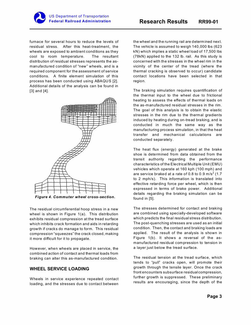
WHEEL MANUFACTURING PROCESS
The commuter operations which experienced the
thermal cracking problems used the same type of
wheels, 32-inch (81 cm) reverse-dish (or S-plate)
wheels. A schematic of the wheel cross-section is
shown in Figure 4. The S-plate is used in
applications in which high-performance stop
braking is required in service. The curved plate
acts like a spring and permits radial breathing of
the rim when it is heated during friction braking.
This action reduces the thermal stresses
developed in the rim of the wheel.
The wheels are manufactured using a multi-step
forging process to initially shape the wheel. Next,
to remove undesired residual stresses which
remain after forging, they are reheated to a
temperature above the austenitizing temperature
(Af=871/C or 1600/F in this example). Once
reheated, the wheels are rim-quenched using a
water spray to produce a fine-grained pearlitic
m i c r o s t r u c t u r e a n d in d u c e b ene f i c ia l
circumferential (hoop) residual compressive stress
at the tread surface. The residual stress
distribution inhibits the formation of fatigue cracks
in the rim and also retards the growth of these
cracks should they manage to form. Following
quenching, the wheels are placed in an annealing
US Department of Transportation
Federal Railroad Administration Research Results RR99-01
Page 3
Figure 4. Commuter wheel cross-section.
furnace for several hours to reduce the levels of
residual stress. After this heat-treatment, the
wheels are exposed to ambient conditions as they
cool to room temperature. The resultant
distribution of residual stresses represents the as-
manufactured condition of “new” wheels, and is a
required component for the assessment of service
conditions. A finite element simulation of th is
process has been conducted using ABAQUS [2].
Additional details of the analysis can be found in
[3] and [4].
The residual circumferential hoop stress in a new
wheel is shown in Figure 1(a). This distribution
exhibits residual compression at the tread surface
which inhibits crack formation and aids in retarding
grow th if cracks do manage to form. This residual
compression “squeezes” the crack closed, making
it more difficult for it to propagate.
However, when wheels are placed in service, the
combined action of contact and thermal loads from
braking can alter this as-manufactured condition.
WHEEL SERVICE LOADING
Wheels in service experience repeated contact
loading, and the stresses due to contact between
the wheel and the running rail are determ ined next.
The vehicle is assumed to weigh 140,000 lbs (623
kN) which implies a static wheel load of 17,500 lbs
(78kN) applied to the 132 lb. rail. As this study is
concerned with the stresses in the wheel rim in the
vicinity of the center of the tread (where the
thermal cracking is observed to occur) candidate
contact locations have been selected in that
region.
The braking simulation requires quantification of
the thermal input to the wheel due to frictional
heating to assess the effects of thermal loads on
the as-manufactured residual stresses in the rim.
The goal of this analysis is to obtain the elastic
stresses in the rim due to the thermal gradients
induced by heating during on-tread braking, and is
conducted in much the same way as the
manufacturing process simulation, in that the heat
transfer and mechanical calculations are
conducted separately.
The heat flux (energy) generated at the brake
shoe is determined from data obtained from the
transit authority regarding the performance
characteristics of the Electrical Multiple Unit (EMU)
vehicles which operate at 160 kph (100 mph) and
are serv ice braked at a rate of 0.8 to 0.9 m/s2 (1.7
to 2 mph/s). This information is translated into
effective retarding force per wheel, which is then
expressed in terms of brake power. Additional
details regarding the braking simulation can be
found in [5].
The stresses determined for contact and braking
are combined using specially-developed software
which predicts the final residual stress distribution.
The post-quenching stresses are used as an initial
condition. Then, the contact and braking loads are
applied. The result of the analysis is shown in
Figure 1(b). It shows a reversal of the as-
manufactured res idual compression to tension in
a layer just below the tread surface.
The residual tension at the tread surface, which
tends to “pull” cracks open, will promote their
growth through the tensile layer. Once the crack
front encounters subsurface residual compression,
further growth is suppressed. These preliminary
results are encouraging, since the depth of the

US Department of Transportation
Federal Railroad Administration Research Results RR99-01
Notice and Disclaimer: This document is disseminated under the sponsorship of the United States Department ofTransportation in the interest of information exchange. Any opinions, findings and conclusions, or recommendationsexpressed in this material do not necessarily reflect the views or policies of the United States Government, nor doesmention of trade names, commercial products, or organizations imply endorsement by the United States Government.The United States Government assumes no liability for the content or use of the material contained in this document.
Page 4
predicted stress reversal corresponds to the
average depth of the cracks which were found in
the wheels of this particular fleet.
CONCLUSIONS
This study has demonstrated an approach for
simulating the effect of service conditions on the
state of residual stresses in wheels. A parallel
effort is underway to obtain estimates of residual
stresses experimentally. The experimental results
will be used to calibrate the model described here.
This will permit application of the simulation
technique to other kinds of rail operations (different
vehicles, speeds, etc.) as well as extension of the
study to freight wheels.
WANT MORE INFORMATION?
Additional details on the manufacturing and serviceloading simulations have been published in twotechnical papers which are available athttp://www.fra.dot.gov.
ACKNOWLEDGMENTS
The work described here was conducted in
support of the FRA’s Rail Equipment Safety
Research Program. Ms. Monique Stewart is the
FRA program manager for this research.
REFERENCES
[1] Orringer, O., Gray, D.E. and McCown, R.J.,
“Evaluation of Immediate Actions Taken to
Deal with Cracking Problems in Wheels of Rail
Commuter Cars,” Final Report, July, 1993.
DOT/FRA/ORD-93/15.
[2] Abaqus/Standard User’s Manual, Volume I
and II (vers ion 5.6). Hibbitt, Karlsson and
Sorenson, Inc., Warwick, RI, 1996.
[3] Gordon, J., “Estimation of Residual Stresses
in Railroad Car Wheels Resulting from
Manufacture and Service Loading,” MS
T h e s i s , D e p a r t m e n t o f M e c h a n ic a l
Engineering, Tufts University, February, 1998.
[4] Gordon, J., Per lman, A.B., “Estimation of
Residual Stresses in Railroad Commuter Car
Wheels Following Manufacture,” ASME
IMECE RTD, November 1998 (in these
proceedings).
[5] Gordon, J., Jones, J.A., and Perlman, A.B.,
“Evaluation of Service-Induced Residual
Stresses in Railroad Commuter Car Wheels,”
ASME IMECE RTD, November 1998.
CONTACTS
Monique F. Stewart
Federal Railroad Administration
Office of Research & Development
1120 Vermont Avenue NW - Mail Stop 20
Washington, DC 20590
TEL (202) 493-6358
FAX (202) 493-6333
e-mail: [email protected]
KEYWORDS: residual stress, railroad wheel,
contact stress, thermal stress, fatigue cracking