Residual Stresses and the Bauschinger Effect
80
Brigham Young University BYU ScholarsArchive All eses and Dissertations 1965-6 Residual Stresses and the Bauschinger Effect Raymond M. Huebner Brigham Young University - Provo Follow this and additional works at: hps://scholarsarchive.byu.edu/etd Part of the Mechanical Engineering Commons is esis is brought to you for free and open access by BYU ScholarsArchive. It has been accepted for inclusion in All eses and Dissertations by an authorized administrator of BYU ScholarsArchive. For more information, please contact [email protected], [email protected]. BYU ScholarsArchive Citation Huebner, Raymond M., "Residual Stresses and the Bauschinger Effect" (1965). All eses and Dissertations. 7122. hps://scholarsarchive.byu.edu/etd/7122
Transcript of Residual Stresses and the Bauschinger Effect
Brigham Young UniversityBYU ScholarsArchive
All Theses and Dissertations
1965-6
Residual Stresses and the Bauschinger EffectRaymond M. HuebnerBrigham Young University - Provo
Follow this and additional works at: https://scholarsarchive.byu.edu/etd
Part of the Mechanical Engineering Commons
This Thesis is brought to you for free and open access by BYU ScholarsArchive. It has been accepted for inclusion in All Theses and Dissertations by anauthorized administrator of BYU ScholarsArchive. For more information, please contact [email protected], [email protected].
BYU ScholarsArchive CitationHuebner, Raymond M., "Residual Stresses and the Bauschinger Effect" (1965). All Theses and Dissertations. 7122.https://scholarsarchive.byu.edu/etd/7122
RESIDUAL STRESSES AND THE
BAUSCHINGER EFFECT
A Thesis
Subm itted to th e M echanical E ng ineering Department
Brigham Young U n iv e rs ity
Provo, Utah
In P a r t i a l F u lf i l lm e n t
Of th e Requirem ents fo r th e Degree o f
M aster o f Science
t>y
Raymond M. Huebner
June, 1965
This t h e s i s , by Raymond M. Huebner, i s accep ted in i t s p re sen t
form by th e Department o f M echanical E ng ineering o f Brigham Young
U n iv e rs ity as s a t i s f y in g th e th e s i s requ irem en ts f o r th e degree o f
M aster o f S c ience .
Date
Typed by fcfery S. Thornton
ACKNOWLEDGEMENT
The a u th o r w ishes to exp ress h is a p p re c ia tio n to the members o f h is
a d v iso ry committee and t o th e Department o f M echanical E ng ineering a t
Brigham Young U n iv e rs ity . P a r t i c u la r a p p re c ia tio n i s extended to D r.
John M. Simonsen and C harles M. P e rc iv a l fo r t h e i r h e lp and guidance.
This th e s i s i s d ed ica te d to th e a u th o r 's p a re n ts , Mr. and Mrs.
Raymond H. Huebner fo r t h e i r con tinued encouragement th roughou t h is
e d u ca tio n .
TABLE OF CONTENTS
iv
C hapter Page
I . INTRODUCTION ............................................................................................. 1
I I . LITERATURE SURVEY.....................................................................................5
I I I . METHOD OF APPROACH.....................................................................................9
Equipment Used Procedure Data R eduction
IV. DISCUSSION OF THE MEASUREMENTS AND RESULTS............................. 3*+
E f fe c t o f E ccen tr ic ity -C a lc u la tio n o f th e Axis o f Average S tra in I n te r p r e ta t io n o f th e MeasurementsI n te r p r e ta t io n o f th e R esu lts
V. CONCLUSIONS AND RECOMMENDATIONS.............................. k j
BIBLIOGRAPHY............................................................................................................U8
APPENDIX 50
CHAPTER I
INTRODUCTION
W ithin th e l a s t te n years th e re has been much i n t e r e s t in th e
f i e l d o f e l a s to - p l a s t i c b ehav io r o f en g in ee rin g m a te r ia ls . Hie re c e n t
p o p u la r i ty o f th e lo w -co st l ig h t-w e ig h t p l a s t i c a l l y designed s t r u c
tu re s h as added a g re a t d e a l o f im petus to t h i s i n t e r e s t . This th e s i s
d e a ls w ith one o f th e a sp e c ts o f e l a s to - p l a s t i c b eh av io r, namely, th e
d i s t r ib u t io n o f th e r e s id u a l s t r e s s e s in a sim ple member which has been
p l a s t i c a l l y deformed in te n s io n a n d /o r compression,. In p a r t i c u l a r , an
a ttem p t has been made to r e l a t e th e se r e s id u a l s t r e s s e s to th e w e ll-
known b u t l i t t l e understood B auschinger e f f e c t .
The B auschinger e f f e c t i s a lo s s o f y ie ld s tre n g th in one d i r e c
t io n which r e s u l t s from a member's be ing p re v io u s ly y ie ld e d in th e
o p p o site d i r e c t io n . For example, when a member i s p l a s t i c a l l y s t r e s s e d
in te n s io n , th e B auschinger e f f e c t causes th e y ie ld p o in t in com pression
to occur a t an a p p re c ia b ly low er s t r e s s th an would be exp ec ted . This
i s shown in F ig u re 1 by th e low er com pressive y ie ld s t r e s s which occurs
a t p o in t D. The occurence o f t e n s i l e y ie ld a ls o causes a n o th e r phenom
enon, c a l le d work h a rd en in g , which causes th e n ex t y ie ld p o in t to occur
a t a s t r e s s h ig h e r th an th e f i r s t one. A lo g ic a l ex p lan a tio n f o r t h i s
beh av io r would be th a t r e s id u a l s t r e s s e s a re formed in th e member in
such a way as to a id th e t e n s i l e y ie ld s tre n g th in one sense and to
h in d e r th e com pressive y ie ld s tre n g th in th e o th e r .
1

2
I t i s p o ss ib le th a t work harden ing may s tre n g th e n th e m a te r ia l
to th e p o in t where th e com pressive y ie ld p o in t o f th e s t r a in e d m a te r ia l
occurs a t a h ig h e r s t r e s s th an th e com pressive y ie ld p o in t o f th e o r ig
in a l u n s tra in e d m a te r ia l . In F ig u re 1, th e l in e GH i s shown lo n g er than
OE.T jV -l
The Bauschinger e f f e c t s t i l l e x is t s because th e r a t i o ^ - equals BCthe r a t i o ——- .CD
---------- Sm all s t r a in---------- Large s t r a in
F ig . 1 . --M echanical H y s te re s is
When a b a r i s a x ia l ly loaded in a t e n s i l e t e s t in g m achine, the
h ig h e s t s t r e s s e s a re known to occur in th e outerm ost f i b e r s . I t i s

3
q u ite n a tu ra l t o assume th a t th e se f ib e r s a re th e f i r s t to y ie ld and
un load . When th e e x te rn a l lo ad on th e b a r i s re la x e d , th e se le s s e r - lo a d e d
o u ts id e f ib e r s w i l l th en be pushed in to com pression by th e c o n tra c tio n o f
th e o th e r f i b e r s . Of co u rse , th e com pressive s t r e s s e s o f th e o u ts id e
f ib e r s would be balanced by t e n s i le s t r e s s e s in th e o th e r f i b e r s . A
rough sk e tch o f t h i s expected r e s id u a l s t r e s s d i s t r ib u t io n i s shown in
F ig u re 2 .
Tension
F ig . 2 . --E xpected r e s id u a l s t r e s s d i s t r ib u t io n in a p l a s t i c a l l y deformed t e n s i l e specim en.
An a ttem p t was made in t h i s s tu d y to show th a t t h i s s i tu a t io n
does occur and th a t i t i s th e cause o f th e B auschinger e f f e c t . This was
accom plished by m easuring and p lo t t in g th e r e s id u a l s t r e s s p a t te rn s
found in b a rs o f s t e e l which had been p re v io u s ly p l a s t i c a l l y deform ed.
The method o f beam d is s e c t io n was s e le c te d f o r th e measurement o f th e se
s t r e s s e s .
k
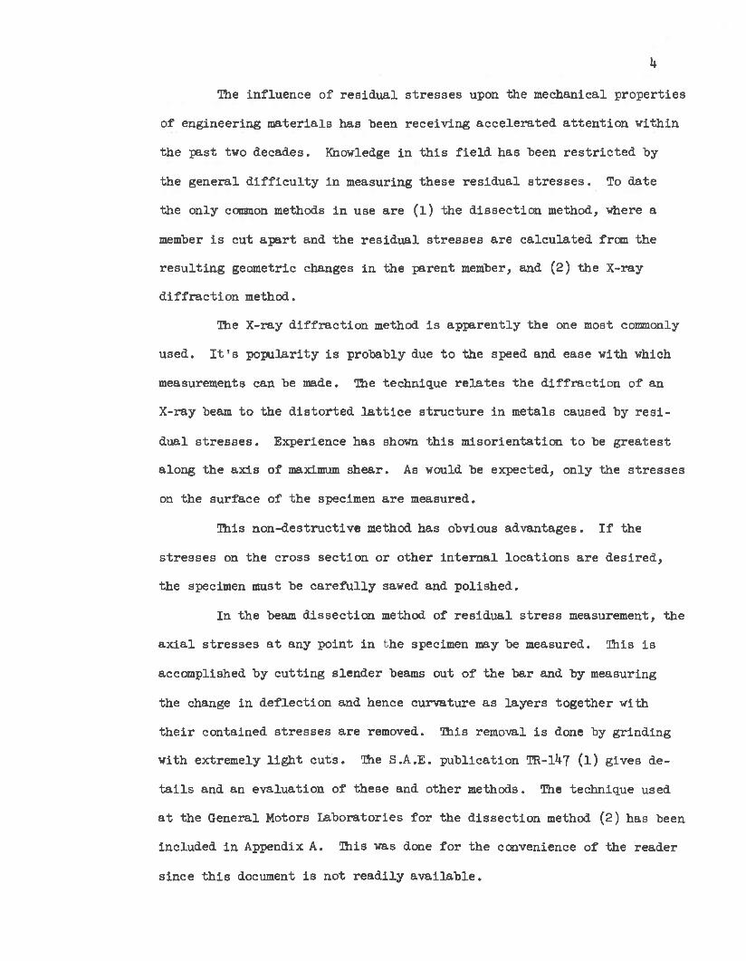
The in f lu e n c e o f r e s id u a l s t r e s s e s upon th e m echanical p ro p e r t ie s
o f en g in ee rin g m a te r ia ls has been re c e iv in g a c c e le r a te d a t t e n t io n w ith in
th e p a s t two decades. Knowledge in t h i s f i e l d has been r e s t r i c t e d by
th e g e n e ra l d i f f i c u l t y in m easuring th e se r e s id u a l s t r e s s e s . To d a te
th e on ly common methods in use a re ( l ) th e d is s e c t io n method, where a
member i s cu t a p a r t and th e r e s id u a l s t r e s s e s a re c a lc u la te d from th e
r e s u l t in g geom etric changes in th e p a re n t member, and (2) th e X -ray
d i f f r a c t io n method.
The X -ray d i f f r a c t io n method i s a p p a re n tly th e one most commonly
u sed . I t ' s p o p u la r ity i s p robab ly due to th e speed and ease w ith which
measurements can be made. The techn ique r e l a t e s th e d i f f r a c t io n o f an
X -ray beam to th e d i s to r te d l a t t i c e s t ru c tu re in m eta ls caused by r e s i
d u a l s t r e s s e s . Experience has shown th i s m iso r ie n ta tio n to be g re a te s t
a long th e a x is o f maximum sh e a r . As would be expected , on ly th e s t r e s s e s
on th e su rfa ce o f th e specimen a re m easured.
This n o n -d e s tru c tiv e method has obvious a d v an tag es . I f the
s t r e s s e s on th e c ro ss s e c tio n o r o th e r in te r n a l lo c a t io n s a re d e s ire d ,
th e specimen must be c a r e f u l ly sawed and p o lish e d .
In th e beam d is s e c t io n method of r e s id u a l s t r e s s measurement, th e
a x ia l s t r e s s e s a t any p o in t in th e specimen may be m easured. This i s
accom plished by c u t t in g s le n d e r beams out o f th e b a r and by m easuring
th e change in d e f le c t io n and hence c u rv a tu re a s la y e rs to g e th e r w ith
t h e i r co n ta in ed s t r e s s e s a re removed. This removal i s done by g rin d in g
w ith ex trem ely l i g h t c u ts . The S .A .E . p u b lic a tio n TR-1^7 ( l ) g ives d e
t a i l s and an e v a lu a tio n o f th e se and o th e r m ethods. The techn ique used
a t th e G eneral Motors L ab o ra to rie s fo r th e d is s e c t io n method (2) has been
in c lu d ed in Appendix A. This was done fo r th e convenience o f th e re a d e r
s in ce t h i s document i s n o t r e a d i ly a v a i la b le .
CHAPTER I I
LITERATURE SURVEY
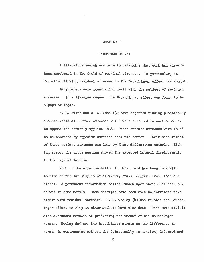
A l i t e r a t u r e search was made to determ ine what work had a lre a d y
been perform ed in th e f i e l d o f r e s id u a l s t r e s s e s . In p a r t i c u la r , i n
fo rm ation l in k in g r e s id u a l s t r e s s e s to th e B auschinger e f f e c t was sough t.
Many papers were found which d e a l t w ith th e s u b je c t o f r e s id u a l
s t r e s s e s . In a lik e w ise manner, th e B auschinger e f f e c t was found to be
a popu lar to p i c .
S . L. Smith and W. A. Wood (3 ) have re p o rte d f in d in g p l a s t i c a l l y
induced r e s id u a l su rfa ce s t r e s s e s which were o r ie n te d in such a manner
to oppose the fo rm erly a p p lie d lo a d . These su rfa ce s t r e s s e s were found
to be balanced by op p o site s t r e s s e s n e a r th e c e n te r . T h e ir measurement
o f th e se su rfa ce s t r e s s e s was done by X -ray d i f f r a c t io n m ethods. E tch
in g a c ro ss th e c ro ss s e c tio n showed th e expected l a t e r a l d isp lacem ents
in th e c r y s ta l l a t t i c e .
Much o f th e ex p erim en ta tion in t h i s f i e l d has been done w ith
to r s io n o f tu b u la r samples o f aluminum, b ra s s , copper, i r o n , le a d and
n ic k e l . A permanent deform ation c a l le d B auschinger s t r a i n has been ob
served in some m e ta ls . Some a ttem p ts have been made to c o r r e la te t h i s
s t r a in w ith r e s id u a l s t r e s s e s . R. L. Wooley (h) has r e la te d th e Bausch
in g e r e f f e c t to s l i p a s o th e r au th o rs have a ls o done. This same a r t i c l e
a ls o d isc u sse s methods o f p re d ic t in g th e amount o f th e B auschinger
s t r a i n . Wooley d e fin e s th e B auschinger s t r a in as th e d if fe re n c e in
s t r a in in com pression between th e ( p l a s t i c a l l y in te n s io n ) deformed and
5

6
undeformed specim ens. Naghdi, Essenburg and Koff (5 ) have t r i e d combin
a t io n s o f to r s io n and te n s io n , and th e r e s u l t i s a " y ie ld s u r fa c e ” on the
s t r e s s - s t r a i n diagram . In t h i s c a se , a B auschinger e f f e c t from to r s io n
b u t n o t te n s io n was observed .
The g ra d u a lly in c re a s in g y ie ld p o in ts in te n s io n r e s u l t in g from
su ccess iv e cy c le s o f p la s t i c deform ation o r work h a rd en in g , a s i t i s
commonly c a l le d , has in s p ire d many th e o r ie s o f y ie ld s t r e n g th . C ry s ta l
l in e a c t io n has re c e iv e d much a t t e n t io n . A. H. C o t t r e l l (6) has
th e o r iz e d a d i s t r ib u t io n o f th e s t r e s s e s among g ra in b o u n d arie s . The
evidence o f low s tre n g th s o f s o f t c r y s ta ls has le d to th e conclusion
th a t c e r ta in sources of s l i p e x i s t in th e se m a te r ia l s . These sources
may have th e a b i l i t y to re le a s e d is lo c a tio n s in to th e surround ings under
sm all a p p lie d s t r e s s e s .
There a re two p o s s i b i l i t i e s f o r th e se so u rc es . They may be d i s
lo c a t io n s a lre a d y in th e c r y s ta ls o r , a l t e r n a t e ly , th e y may be c r y s ta l
boundaries o r im p erfec tio n s o f o th e r k inds from which d is lo c a t io n s can
be c re a te d under sm all s t r e s s e s . C o t t r e l l has a ttem p ted to ex p la in
both work h arden ing and th e B auschinger e f f e c t by th e o r iz in g th a t th ese
m obile d is lo c a t io n s became p i le d up o r trap p ed a t some b a r r i e r , i . e . ,
a g ra in boundary.
The mechanisms o f p la s t i c flow and f r a c tu re seem to have rece iv ed
most o f th e a t te n t io n in t h i s f i e l d . An a p p re c ia b le amount o f t h i s work
has been ex p erim en ta tio n w ith s in g le c r y s t a l s . One o f th e th e o r ie s o f
p la s t i c flow given by C o t t r e l l i s t h a t th e ap p aren t y ie ld s t r e s s shown
by a t e n s i l e specimen i s low er than th e a c tu a l y ie ld s t r e s s o f th e m ate r
i a l . The y ie ld in g seems to be i n i t i a t e d a t seme lo c a t io n o f h igh s t r e s s
c o n c e n tra tio n and th en sp reads through th e m a te r ia l by th e a c t io n o f h igh
7
s t r e s s around th e y ie ld e d p o r t io n . For a s in g le iro n c r y s ta l , th e r a t i o
o f th e th e o r e t ic a l y ie ld s t r e s s to th e ap p aren t y ie ld s t r e s s v a r ie s from
two to t h r e e . Evidence th a t y ie ld in g spreads in t h i s way i s g iven by
observed su rfa ce m arkings, i . e . , Luders bands. These bands a re v is ib le
l in e s ap p earin g on th e su rfa ce o f a y ie ld e d member. The p r e f e r e n t ia l
growth o f th e se bands a long l in e s 1+5° to th e p r in c ip a l s t r e s s e s has been
used as evidence th a t o v e rs tra in e d m a te r ia l does n o t support sh ea r s t r e s s e s .
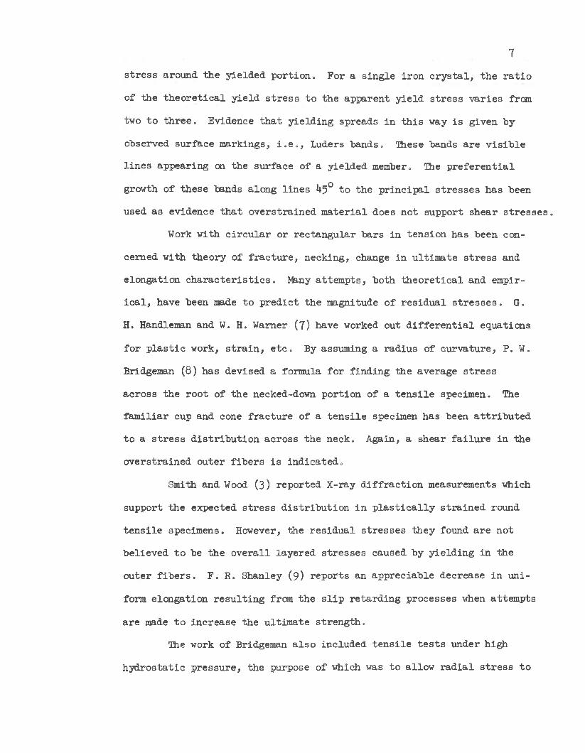
Work w ith c i r c u la r o r re c ta n g u la r b a rs in te n s io n has been con
cerned w ith th e o ry o f f r a c tu r e , neck ing , change in u ltim a te s t r e s s and
e lo n g a tio n c h a r a c t e r i s t i c s . Jfeny a tte m p ts , bo th th e o r e t ic a l and em pir
i c a l , have been made to p re d ic t th e magnitude o f r e s id u a l s t r e s s e s . G.
H. Handleman and W. H. Warner (7 ) have worked out d i f f e r e n t i a l equations
fo r p la s t i c work, s t r a i n , e t c . By assum ing a ra d iu s o f c u rv a tu re , P. W.
Bridgeman (8) has dev ised a form ula f o r f in d in g th e average s t r e s s
a c ro ss th e ro o t o f th e necked-down p o r tio n o f a t e n s i l e specim en. The
f a m il ia r cup and cone f r a c tu re o f a t e n s i l e specimen has been a t t r ib u te d
to a s t r e s s d i s t r ib u t io n a c ro ss th e neck . A gain, a sh ea r f a i lu r e in the
o v e rs tra in e d o u te r f ib e r s i s in d ic a te d .
Smith and Wood (3) re p o rte d X -ray d i f f r a c t io n measurements which
support th e expected s t r e s s d i s t r ib u t io n in p l a s t i c a l l y s t r a in e d round
te n s i l e specim ens. However, th e r e s id u a l s t r e s s e s th e y found a re n o t
b e lie v e d to be th e o v e ra l l la y e red s t r e s s e s caused by y ie ld in g in th e
o u te r f i b e r s . F . R. Shanley (9) re p o r ts an a p p re c ia b le d ecrease in u n i
form e lo n g a tio n r e s u l t in g from th e s l i p r e ta rd in g p ro cesses when a ttem p ts
a re made to in c re a se th e u ltim a te s t r e n g th .
The work o f Bridgeman a ls o in c lu d ed t e n s i l e t e s t s under h igh
h y d ro s ta t ic p re s su re , th e purpose o f which was to a llo w r a d ia l s t r e s s to

8
be a c t iv e on th e o u ts id e o f th e specimen as w e ll a s w ith in . Thus f a r , no
r e la t io n s h ip has been found to p re d ic t th e a x ia l s t r e s s a c ro ss th e
c ro ss s e c tio n o f th e p l a s t i c a l l y deformed specim en.
S ev e ra l w orkers, e s p e c ia l ly those who used a com bination o f t o r
s io n and te n s io n , re p o r t agreem ent w ith o r a t l e a s t support o f th e Von
Mises y ie ld s tre n g th th e o ry . John Nunes (10) and some o f th e o th e rs use
B ridgem an's form ulas to determ ine a t ru e s t r e s s - s t r a i n curve f o r th e
necked down p o r tio n o f a t e n s i l e specimen and claim accu racy w ith in a
few p e rc e n t.
P rager ( l l ) has dev ised id e a l iz e d m echanical modesl to d e sc rib e
th e lo a d - s t r a in c h a r a c te r i s t i c s o f such m a te r ia ls as p e r f e c t ly p l a s t i c ,
e l a s t i c , work h a rd en in g , e t c . S t r e s s - s t r a in curves based on Bridgem an's
form ulas a re a ls o g iv en . One R ussian a u th o r , A. M. V asilev (1 2 ), c laim s >
t h a t one o f h is papers p re d ic ts th e B auschinger e f f e c t from X -ray d i f
f r a c t io n d a ta . No o th e r re fe re n c e s o f t h i s type were found.

CHAPTER I I I
METHOD OF APPROACH
Equipment Used
Hie equipment used fo r th e s tu d y c o n s is te d o f s t e e l specim ens,
t e s t in g machines capable o f e x e r tin g t e n s i l e and com pressive fo r c e s ,
e l e c t r i c s t r a in gages and th e a s s o c ia te d in s tru m e n ts , a b a l l j o i n t
ap p ara tu s to p rov ide a p u re ly a x ia l fo rce fo r com pression, a cu rv a tu re
m easuring a p p a ra tu s , and a su rfa ce g r in d e r .
The m ajor requ irem en ts f o r th e desig n o f th e specimens a re l i s t e d
as fo llo w s:
1 . The le n g th and th e w idth o f beams should be no g re a te r than
n e ce ssa ry in o rd e r to p rev en t ex cessiv e g rin d in g tim e .
2 . The geom etry o f the beams must perm it a s u f f i c i e n t ly t i g h t
g r ip by th e m agnetic chuck.
3 . The s iz e and type o f th e specimens must be com patib le w ith
th e t e s t in g machines a v a i la b le .
U. Hie c ro ss s e c tio n o f th e specimens should p rovide a smooth
s t r e s s flow .
5 . Hie f in is h e d specimens must be f r e e from re s id u a l s t r e s s .
The s tan d a rd round t e n s i l e specimen w ith th read ed ends was used
fo r th e s t a r t i n g p o in t o f th e d e s ig n . The beam was c u t no lo n g e r than
th e narrow se c tio n o f th e specim en. Hie beam could have been lo n g e r as
i t was d u rin g th e p re lim in a ry ru n s , b u t i t was f e l t t h a t th e m a te r ia l
in the th read ed ends, being devoid o f s t r e s s , would c o n tr ib u te n o th in g
9

10
to the measured d a ta . Hie om ission o f t h i s unneeded le n g th r e s u l te d in
a s u b s ta n t ia l re d u c tio n in m achining and g rin d in g tim e .
F igu re 3 shows th e o r ig in a l beam which was c u t from a s tan d a rd
round specim en. The m a te r ia l from th e th read ed ends was used in th i s
c a se . I t was found th a t th e rounded edge could cause some d i f f i c u l t y
when th e beam i s h e ld in th e m agnetic chuck. A lso , i t was found to be
q u ite in co n v en ien t to c u t f l a t s on th e ends o f th e beam e x a c tly even
w ith th e to p o f th e rounded edge .
S ec tio n A-A
F ig . 3 - —A Beam Cut from a S tandard Round Specimen.
I t may a ls o be seen th a t th e rounded edge would in tro d u ce a con
s id e ra b le amount o f e r r o r i f Cut No. 2 were u sed . As a remedy f o r both
o f th e se problem s, i t was decided to use a f la t te n e d specimen which
would perm it th e c u t t in g ou t o f a beam o f re c ta n g u la r c ro ss s e c t io n .
A beam w idth o f 0 .1 in . was a r b i t r a r i l y chosen to s a t i s f y requ irem ent
No. 1 . The f l a t s on th e specimen were made 0 .3 in . wide to p rov ide a
b u f fe r a re a f o r s t r e s s s t a b i l i z a t i o n on bo th s id e s o f th e beam. The
f i n a l c o n fig u ra tio n o f th e specimens i s shown in F ig u re h .
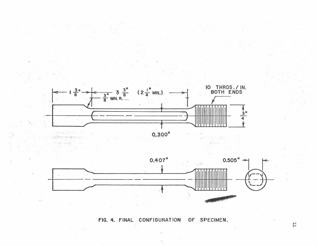
FIG. 4 . FINAL CONFIGURATION OF SPECIMEN.
12
The t e s t in g machine used f o r th e t e n s i l e phase o f th e s tu d y was
the R ieh le 120,000 l b . T es tin g Machine which i s lo c a te d in th e C iv il
E ng ineering L abora to ry a t Brigham Young U n iv e rs ity - The m ajor advan
tag es o f t h i s machine were smooth c o n tro l o f th e load and a s e lf -c o n ta in e d
lo a d - s t r a in p lo t t in g system .
For th e com pression phase o f the s tu d y , th e machine used was a
Baldwin-Tate-Em ery T estin g Machine, Type PTE 93, w ith 30,000 lb . capa
c i t y . This machine i s a ls o lo c a te d in th e C iv i l E ng ineering L abora to ry
a t Brigham Young U n iv e rs ity . The s t r a in measurements in t h i s case were
made w ith e l e c t r i c a l s t r a in gages.
Three ty pes o f s t r a in gages have been t r i e d ; th e y were sim ple
paper backed gages, d u a l-w ire paper backed gages (both o f th e SR-U
v a r ie ty ) and epoxy backed g a g es . A ll th re e o f th e se ty p es may be tem
p e ra tu re compensated fo r th e common m e ta ls . The sim ple paper-backed
gages were p re fe r re d because o f th e ease o f t h e i r i n s t a l l a t i o n and t h e i r
low p r ic e .
The cements used fo r th e se gages were Duco fo r th e paper gages
and Budd B-12 Epoxy Cement o r Eastman 910 Cement f o r th e epoxy g a g es .
The l e a s t success was experienced w ith th e Eastman 910 Cement; however,
t h i s could be due to in s u f f ic ie n t cu rin g tim e a n d /o r th e o ld age o f th e
cement on hand. The ex trem ely f a s t harden ing tim e o f th e Eastman 910
Cement i s a d e f in i t e advantage and th e p o s s i b i l i t i e s should be i n v e s t i
g a ted f u r th e r .
The o u tp u t o f th e s t r a in gages used was measured by an i n s t r u
ment which c o n s is te d o f a com bination o f a b r id g e , a t r a n s i s t o r am p li
f i e r , and a m e te r. This in s tru m e n t, m anufactured by E l l i s A sso c ia te s ,
L td . , was d e sig n a ted BAM-1.
13
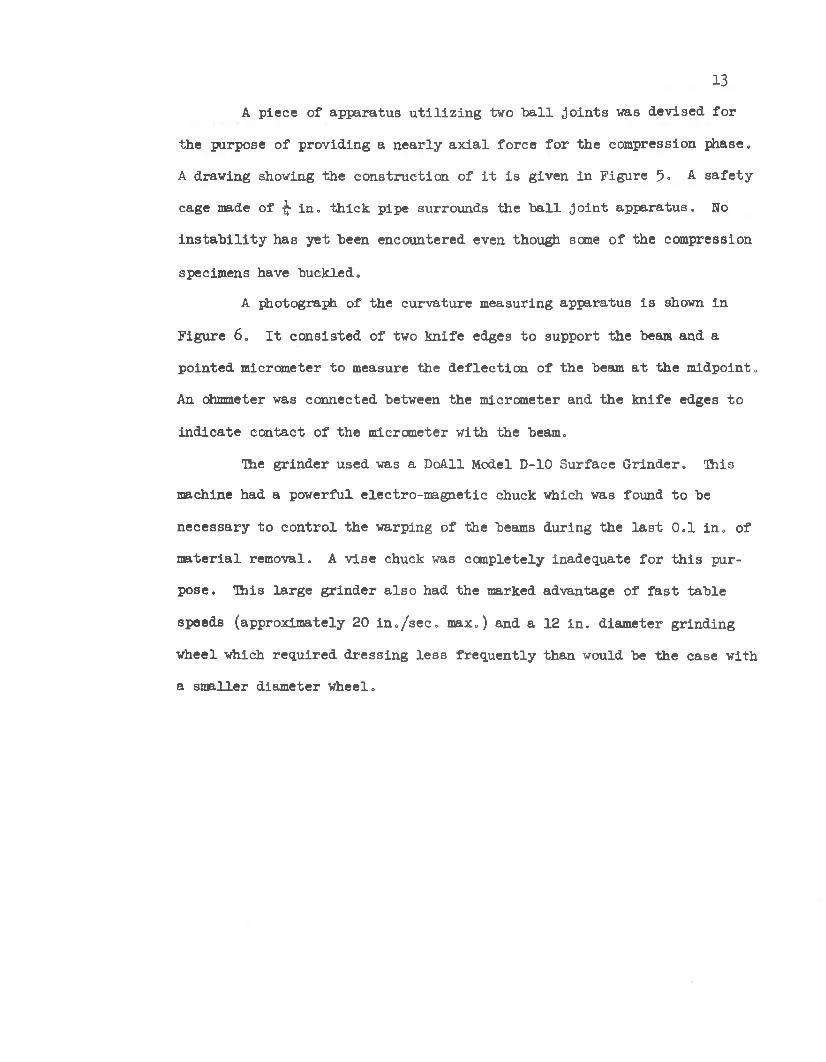
A p iece o f a p p a ra tu s u t i l i z i n g two b a l l j o in t s was d ev ised fo r
th e purpose o f p ro v id in g a n e a r ly a x ia l fo rc e f o r th e com pression phase.
A drawing showing th e c o n s tru c tio n o f i t i s g iven in F igure 5° A s a f e ty
cage made o f ^ i n . th ic k p ipe surrounds th e b a l l j o i n t a p p a ra tu s . No
i n s t a b i l i t y has y e t been encountered even though setae o f th e com pression
specimens have buck led .
A photograph o f th e cu rv a tu re m easuring ap p ara tu s i s shown in
F igu re 6 . I t c o n s is te d o f two k n ife edges to support th e beam and a
p o in ted m icrom eter to measure th e d e f le c t io n o f th e beam a t th e m idpo in t.
An ohmmeter was connected between th e m icrom eter and th e k n ife edges to
in d ic a te c o n tac t o f th e m icrom eter w ith th e beam.
'Hie g r in d e r used was a DoAll Model D-10 S urface G rin d e r. This
machine had a pow erful e lec tro -m ag n e tic chuck which was found to be
n ecessa ry to c o n tro l th e warping o f th e beams du rin g th e l a s t 0 .1 in . o f
m a te r ia l rem oval. A v is e chuck was com pletely inadequate f o r t h i s p u r
pose . This la rg e g r in d e r a ls o had th e marked advantage o f f a s t ta b le
speeds (approx im ate ly 20 i n . / s e c . m ax.) and a 12 in . d iam eter g rin d in g
w heel which re q u ire d d re s s in g le s s f r e q u e n tly th an would be th e case w ith
a sm a lle r d iam eter w heel.

BALL JOINT SPECIMEN HOLDER FOR COMPRESSION
FIG. 5. DRAWING OF COMPRESSION APPARATUS.

F ig . 6 . —C urvature M easuring A pparatusHvn
Procedure
1.6
I t was b e lie v e d th a t any s t e e l would g ive th e d e s ire d r e s id u a l
s t r e s s e s a f t e r f i r s t b e in g p l a s t i c a l l y y ie ld e d . However, s in ce th e
Bauschinger e f f e c t was o f prime im portance, a t l e a s t th re e d i f f e r e n t
ty p es o f s t e e l were t r i e d in a search fo r t h i s phenomenon. A v e ry low-
carbon m ild s t e e l , a s t e e l w ith a mid range carbon c o n te n t, and an
e a s i ly o b ta in ed a l lo y s t e e l were in v e s t ig a te d . These th re e s t e e l s were
d e sig n a ted 1018, 1CA-5 and l l¥ j- . On the b a s is o f showing a r e s id u a l
s t r e s s p a t te rn and e x h ib it in g the B auschinger e f f e c t , each o f th e se th re e
s te e l s seemed to be e q u a lly s u i te d . The 10l8 s t e e l was a r b i t r a r i l y
chosen. A p a r t i a l s t r e s s s t r a i n diagram fo r annealed 1018 s t e e l i s
g iven in F igure 7.
Both e l e c t r i c s t r a in gages and th e d i f f e r e n t i a l tran sfo rm er ex
ten s io m ete r were used; th e re fo re , i t was n e ce ssa ry to compare th e o u tpu t
o f each w ith a known s ta n d a rd . Hie d i f f e r e n t ia l - t r a n s f o r m e r s t r a in
m easuring system was c a l ib ra te d w ith an e l e c t r i c r e s is ta n c e w ire s t r a in
gage which in tu rn was c a l ib ra te d w ith a m echanical d ia l-g a g e e x te n s io
m e te r. A more d i r e c t method was p re fe r re d , b u t m echanical d i f f i c u l t y
was encoun tered . When h igh ranges o f s t r a i n were measured w ith the
e l e c t r i c s t r a in gages, th e re was some d i f f i c u l t y encountered in o b ta in
in g a s u f f i c i e n t ly h igh c a l ib r a t io n p o in t on th e m eter s c a le . The ga in
c o n tro l on th e b rid g e would n o t go low enough to perm it th e d e s ire d
c a l ib r a t io n p o in t . This was e a s i ly rem edied by adding a 10,000 ohm
p o ten tio m e te r in s e r ie s w ith th e common w ire which le d to both th e
a c t iv e and th e com pensating g a g es . No adverse e f f e c t on th e m easure
ments r e s u l te d .
The la b o ra to ry techn iques used fo r th e i n s t a l l a t i o n o f th e s t r a in
gages have been in c lu d ed fo r convenience.
IT
The c o n s is te n t ly su c c e ss fu l method f o r i n s t a l l i n g th e s t r a in
gages i s o u tlin e d as fo llo w s: F i r s t th e specimen i s c a r e f u l ly p o lish ed
to remove a l l oxide and to o l m arks. I t i s th en c leaned by swabbing
w ith a m ixture o f 1 p a r t (by volume) xylene and 2 p a r ts m e th y l-e th y l-
key tone. This c lean in g s te p could j u s t as w e ll have been done by
swabbing f i r s t w ith to lu o l and then ace to n e . Roughening th e su rface
o f the specimen w ith 180 to 220 g r i t emery c lo th i s a ls o recommended.
When paper gages a re i n s t a l l e d , a l i b e r a l co a t o f Duco cement
i s a p p lie d to each s id e o f th e gage. The a i r bubbles and excess cement
a re c a r e f u l ly worked away from th e gage by firm f in g e r p re s su re . A
p iece o f foam ru b b e r, p ro te c te d by a s t r i p o f waxed pap er, i s used to
a p p ly p re ssu re to th e gage du rin g th e i n i t i a l s tag e o f th e d ry in g . Hie
p iece o f foam rubber should overlap th e gage by a t l e a s t l / 8 in . on a l l
s id e s . Tape, a w eight o r a clamp may be used to ho ld th e sponge rubber
in p la c e . The p re ssu re should be 1-2 p s i . S ince Duco i s a so lv e n t-
escape cement, no covering should be l e f t over th e gage fo r more than
20 m in u te s .
When epoxy gages a re i n s t a l l e d , th e cem enting procedure i s
s l i g h t l y more in v o lv ed . A fte r th e su rfa ce o f th e specimen i s roughened
and, o f co u rse , c leaned a g a in , a l i g h t co a t o f Budd M etal C ond itioner
No. 1 i s a p p lie d to th e specim en. This s o lu tio n i s a p p a re n tly a m ild
o x id iz in g ag en t s im ila r to gun b lu e in g . The s te p j u s t m entioned a p p lie s
only to fe rro u s m e ta ls .
The back s id e o f th e epoxy gages should be c a r e f u l ly roughened
w ith an ex trem ely f in e emery pap er, i . e . , 500 g r i t p ap er. Care must be
taken to avo id sanding through to th e m eta l f i lm . When Budd B-12 Cement
i s u sed , th e foam rubber p re ssu re pads should be l e f t in p lace du rin g

18
the e n t i r e 12 hour cu rin g p e r io d . When Eastman 910 Cement i s u sed , an
a c c e le r a to r may he coated on th e gage, and th e cement w i l l then cure
a lm ost im m ediately.
During th e e a r ly p a r t o f t h i s p e rio d o f re s e a rc h , e l e c t r i c i a n ’s
p la s t i c tap e was t i g h t l y wrapped around th e gage a f t e r th e cement had
cu red . This was an a ttem p t to p ro te c t th e gage bo th from m oistu re and
m echanical damage. A comparison o f th e accu racy o f tap ed and untaped
gages showed th i s p ra c t ic e o f ta p in g to he q u ite d e tr im e n ta l .
One o f the g r e a te s t su sp ec ts o f experim en tal e r r o r in work of
t h i s k ind i s bending caused by the load -p roducing a p p a ra tu s . This bend
in g would n o t only a f f e c t th e r e s id u a l s t r e s s m easurem ents, b u t would
a ls o in f lu e n c e th e column a c tio n o f th e specimen d u rin g com pression, thus
causing prem ature b u ck lin g . Means were d ev ised to reduce th e e f f e c t s
o f t h i s bending from app rox im ate ly 15 to 3 per c e n t.
The s p h e r ic a l jo in t s in th e t e n s i l e f ix tu r e s o f th e t e s t in g
machine were f i r s t c lean ed , lapped and lu b r ic a te d . This d id n o t reduce
th e bending in te n s io n to an accep tab le v a lu e , so th e a x is o f average
d e f le c t io n fo r te n s io n was found. With th e lo c a t io n o f t h i s a x is known,
the beams to be used f o r d is s e c t io n were c u t from t h i s most fav o rab le
p o s i t io n . C hapter IV g ives an ex p lan a tio n o f t h i s c a lc u la t io n . The
term , a x is o f average d e f le c t io n , i s used because th e e x p re ss io n , n e u tr a l
a x is , does n o t r i g i d ly ap p ly to a s t r e s s f i e l d composed o f te n s io n and
ben d in g .
The bending du rin g th e se t e s t s was e v a lu a ted by making s t r a in
measurements a t U lo c a t io n s sym m etrically chosen around th e p e rip h e ry
o f a c i r c u la r t e s t specim en. A photograph o f a ty p ic a l round specimen
w ith fo u r s t r a in gages a tta c h e d i s shown in F igu re 8 . For convenience.

19
th e fo u r compass d ir e c t io n s were chosen as th e lo c a t io n s fo r s t r a in
measurement. In accu racy caused by th e in d iv id u a l e r ro r s o f th e gages
and e c c e n t r ic i ty o f th e specimen was minimized by r o ta t in g th e specimen
in i t s h o ld e rs 90° a f t e r each run u n t i l each compass d i r e c t io n had been
occupied by each o f th e fo u r gages.
A sm all amount o f bending (approx im ate ly 8$) was found to e x is t
in th e specimen du rin g com pression t e s t s , so ag a in th e a x is o f average
d e f le c t io n was c a lc u la te d . Ihe com plete system used f o r com pression i s
shown in F igu re 9-

20
FIG. 7. PARTIAL STRESS STRAIN DIAGRAM FOR ANNEALED 1016 STEEL.
NOTE * THE TEST WAS TERMINATED BEFORE THE NECKING POINT WAS REACHED.

21
F ig . 8 . —Round Specimen w ith Four S tr a in Gages A ttach ed .

ioF ig . 9»—System Used f o r Compression

Freedom from re s id u a l s t r e s s in th e specimens was a ssu re d by-
hav ing them annea led in an i n e r t atm osphere a t a commercial h e a t t r e a t
in g f a c i l i t y .
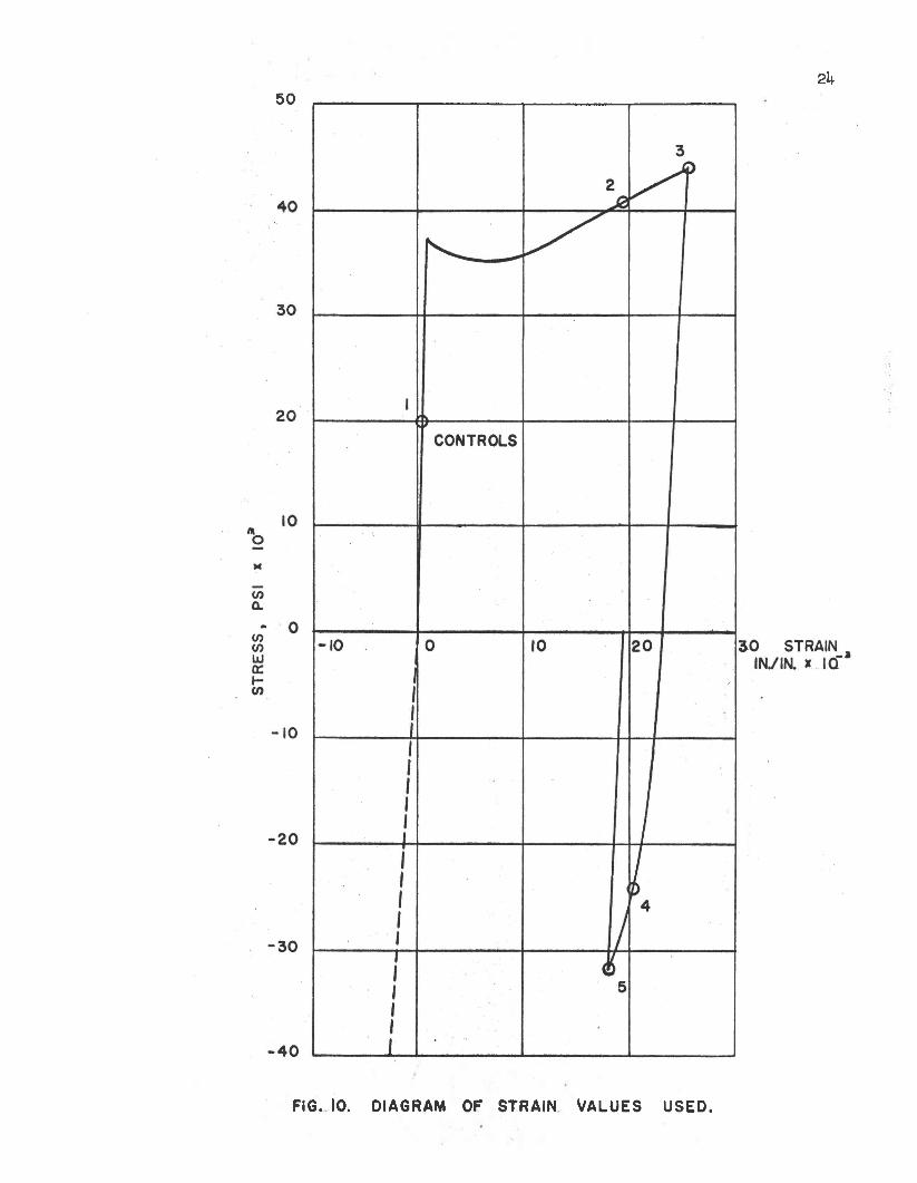
I t was co n sidered d e s ir a b le t o s t r a i n th e specimens to ap p ro x i
m ate ly f iv e d i f f e r e n t p o in ts on th e s t r e s s - s t r a i n d iagram . The p o in ts
were a r b i t r a r i l y chosen. The p o in t used f o r th e c o n tro ls was a p p ro x i
m a te ly halfw ay up th e e l a s t i c p o r tio n o f th e t e n s i l e s id e o f th e d ia
gram. Two more p o in ts were chosen in th e work h arden ing reg io n o f th e
t e n s i l e s id e . The p o in t o f u ltim a te s tre n g th was n o t used because i t
was b e lie v e d th a t th e most pronounced extrem es in th e r e s id u a l s t r e s s
p a t te rn s would occur a t seme p o in t e a r ly in th e work harden ing reg io n
where a l l f ib e r s had n o t y ie ld e d th e same amount.
A ll o f th e com pression specimens were f i r s t p u lle d to p o in t No.
3 , th e maximum te n s i l e s t r a in used , and th en compressed to one o f th e
two com pression p o in ts u sed . Most o f th e specimens cou ld be compressed
beyond th e 5 ,000 p i n / i n p o in t even though a few o f them d id b u c k le .
I f more specimens had been a v a i la b le , a n o th e r p o in t a t a h ig h e r com
p re s s iv e s t r a i n would have been u sed . A lso , a p o in t o f pure compres
s iv e s t r a in (w ithou t p r io r t e n s i l e s t r a i n ) would have been used f o r
purposes o f com parison.
The p o in ts o f s t r a i n which were used a re l i s t e d a s fo llo w s:
P o in t No. S tr a in Used p, i n . / i n .
123k5
Tension, TOO C ontro ls T ension, 19,300 T ension , 25,200T ension, 25,200; Compression, 3 ,000 T ension, 25,200; Compression, 5 ,000
This in fo rm atio n i s p re sen ted g ra p h ic a l ly in F igure 10.
502k
FIG. 10. DIAGRAM OF STRAIN VALUES USED.
25
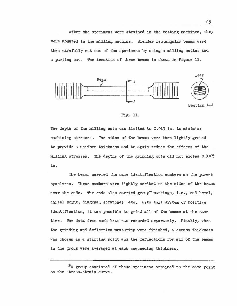
A fte r th e specimens were s t r a in e d in th e t e s t in g m achines, th e y
were mounted in th e m ill in g m achine. S len d er re c ta n g u la r beams were
th en c a r e f u l ly c u t ou t o f th e specimens by u s in g a m il l in g c u t te r and
a p a r t in g saw. The lo c a t io n o f th e se beams i s shown in F igu re 11.
Beam
The dep th o f th e m il l in g c u ts was l im ite d to 0.015 in . to minimize
m achining s t r e s s e s . The s id e s o f th e beams were then l i g h t l y ground
to p rov ide a uniform th ic k n e ss and to ag a in reduce th e e f f e c t s o f the
m il l in g s t r e s s e s . The dep ths o f th e g rin d in g c u ts d id n o t exceed 0.0005
in .
The beams c a r r ie d th e same id e n t i f i c a t io n numbers a s th e p a re n t
specim ens. These numbers were l i g h t l y sc r ib e d on th e s id e s o f th e beams
n e a r th e ends. The ends a ls o c a r r ie d group* m arkings, i . e . , end b e v e l,
c h is e l p o in t , d iag o n a l s c ra tc h e s , e t c . With t h i s system o f p o s i t iv e
i d e n t i f i c a t io n , i t was p o s s ib le to g rin d a l l o f th e beams a t th e same
tim e . The d a ta from each beam was reco rded s e p a ra te ly . F in a l ly , when
the g rin d in g and d e f le c t io n m easuring were f in is h e d , a common th ic k n e ss
was chosen as a s t a r t in g p o in t and th e d e f le c t io n s fo r a l l o f th e beams
in th e group were averaged a t each succeeding th ic k n e s s .
group c o n s is te d o f th ose specimens s t r a in e d to th e same p o in t on th e s t r e s s - s t r a i n cu rv e .
26
The procedure o u tlin e d by th e G eneral Motors Research L ab o ra to r
ie s (2) was s t r i c t l y fo llow ed w hile th e beams were be ing ground. Any
g rin d in g cu ts eq u al to o r g re a te r than 0.0005 i n . may be expected to in
tro d u ce r e s id u a l s t r e s s e s . M. I . H etenyi (13) g ives seme in te r e s t in g
v a lu es f o r r e s id u a l s t r e s s e s caused by g r in d in g . A copy o f th e p ro
cedure f o r beam d is s e c t io n can be found in th e appendix o f t h i s t h e s i s .
A ll tw enty specimens were ground a t once; approx im ate ly te n
hours were re q u ire d fo r each o f th e fo u r te e n d e f le c t io n measurements ta k en .
The s ig n convention fo r th e c u rv a tu re was the same one used by
Henry S. Todd ( l 4 ) . When th e edge being ground away was p laced n ex t to
th e gage, a convex-downward cu rv a tu re was regarded a s p o s i t iv e . The i n
board edge o f th e beam i s u s u a lly ground away f i r s t . The g rin d in g of
t h i s edge f i r s t has been d esig n a ted "Cut No. 1 ." O ccasio n a lly , i t i s
d e s ir a b le to change to Cut No. 2 and g r in d th e outboard edge. This i s
n e c e ssa ry when th e cu rv a tu re o f th e beams causes d i f f i c u l t y in h o ld in g
th e beams on a m agnetic chuck. Only Cut No. 1 was used in t h i s s tu d y .
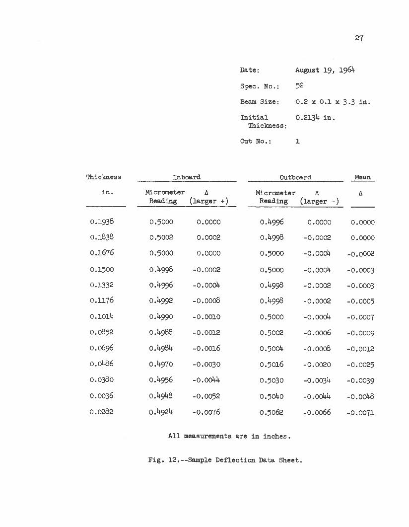
The d e f le c t io n s were m easured on bo th s id e s o f each beam and th e average
o f th e two measurements was used fo r cu rv a tu re and s t r e s s c a lc u la t io n .
A sample d a ta sh e e t i s g iven in F igu re 12.
The m athem atical r e la t io n s h ip s between th e removed s t r e s s e s and
th e c u rv a tu re changes in th e beams i s given in Appendix A. Hand c a lc u
l a t io n o f th e se s t r e s s e s i s an ex trem ely tim e-consum ing p ro c e ss . Henry
S. Todd (lU ) has p repared a program f o r th e c a lc u la t io n o f th e r e s id u a l
s t r e s s e s on a d i g i t a l cam putor. A s l i g h t l y m odified v e rs io n o f t h i s p ro
gram was used in t h i s s tu d y . A copy o f t h i s m odified program i s given
in Appendix E.
27
Date:
Spec. No.:
Beam S ize :
I n i t i a l T h ickness:
Cut No.:
August 19, 1961+
52
0 .2 x 0 .1 x 3-3 in .
O.213I* in .
l
Thickness Inboard Outboard Mean
in . M icrometerReading
A( la r g e r +)
M icrometerReading
A( la rg e r - )
A
0.1938 0.5000 0.0000 0 .1*996 0.0000 0.0000
O.1838 0.5002 0.0002 0 .1*998 -0 .0002 0.0000
O.1676 0.5000 0.0000 0.5000 -o.oooi* -0.0002
0.1500 0.1*998 -0.0002 0.5000 -o.oooi* - 0.0003
0.1332 0.1*996 -o.oooi* 0 .1*998 -0 .0002 - 0.0003
0.1176 0 .1*992 -0 .0008 0 .1*998 -0 .0002 - 0.0005
0.101U 0 .1*990 -0 .0010 0.5000 -o.oooi* - 0.0007
0.0852 0.14-988 -0.0012 0.5002 -0.0006 -0.0009
O.0696 0 .1*981* -0.0016 0.5001* -0.0008 -0.0012
0.0U86 0,1*970 -0 .0030 0.5016 -0 .0020 -0.0025
0.0380 0.1*956 -0.001*1* 0.5030 - 0 . 0031* - 0.0039
0.0036 0.1*91*8 -0.0052 0 . 501+0 -0.001*1* -o.ooi*8
0.0282 O.I+92I* -0.0076 0.5062 -0.0066 - 0.0071
A ll measurements a re in in c h e s .
F ig . 1 2 .—Sample D e fle c tio n Data S h ee t.

Data Reduction
28
Because o f th e n a tu re o f th e d a ta measured in t h i s work, th e re
e x is t s a need f o r one o r more s te p s o f d a ta sm oothing. As th e procedure
now s ta n d s , a d e f in i te smoothing ta k es p lace th re e tim es be fo re th e
s t r e s s e s a re c a lc u la te d .
When th e d e f le c t io n o f th e beams was m easured, read in g s were taken
on both th e to p and th e bottom o f th e beam. The average o f th e two values
i s re co rd ed . There i s a p ro v is io n in th e computer program to use d e f le c
t io n measurements from bo th s id e s s e p a ra te ly , b u t i t was found to be
exped ien t to average the two va lu es and in p u t th e d a ta on ly once to th e
com puter. The sample d a ta s h e e t. F ig u re 12, shows th a t a co n sid e rab le
amount o f smoothing took p lace in t h i s s te p .
When a beam r e s t s on th e c u rv a tu re m easuring gage, th e w eight o f
th e overhanging ends causes a s l ig h t e r r o r in th e c u rv a tu re . This may be
c o rre c te d by th e in p u t o f a c o n sta n t to th e s t r e s s c a lc u la t io n program.
The use o f t h i s c o n sta n t i s ex p la in ed in Appendix F . However, t h i s e r ro r
becomes s e l f - c o r r e c t in g when th e cu rv a tu re i s measured on bo th s id e s of
th e beam. A lso , th e e r r o r caused by a s l ig h t b u rr on one s id e o f the
beam i s reduced to o n e -h a lf by t h i s method.
The second smoothing o f th e d a ta was accom plished by th e av erag in g
to g e th e r o f th e d e f le c t io n s o f th e 2 to 6 specimens in each group.
O bviously, i t was d e s ire a b le to have a s many specimens in a group
a s p o s s ib le . When th e d a ta from each of th e beams in a group i s averaged
to g e th e r , i t i s hoped th a t many of th e in d iv id u a l d if f e re n c e s would d i s
ap p ea r. Inc luded would be sm all amounts o f e c c e n t r ic i ty , unusual machin
ing s t r e s s e s , e t c .
29
The t h i r d smoothing o f th e d a ta ta k es p lace when th e computer
program a p p lie s a curve f i t t i n g procedure to th e in p u t d a ta . The r e l a
t i v e l y com plicated s t r e s s com putation , th e n , ta k es p lace on in p u t d a ta
which i s known to be smooth. This saves machine tim e and improves the
accu racy o f th e o u tp u t. A lso , w ith t h i s method, i t i s much e a s ie r fo r
th e program u se r to check th e accu racy o f th e curve f i t . The cu rv a
tu re : o f th e beam as measured may be q u ic k ly c a lc u la te d from th e r e l a
t io n s h ip :
C 2A
1 + A(1)
A i s th e d e f le c t io n o f th e c e n te r o f th e beam measured in in c h es ,
and C i s th e cu rv a tu re in in c h es”1 .
o r C « 2A fo r A ^ 0.0075 in . (2)
When th e computed s t r e s s e s were f i r s t re c e iv e d from th e computa
t io n s e c t io n , th e q u es tio n im m ediately a ro se concern ing which o f th e
eq uation o rd ers gave the b e s t curve f i t . The obvious s o lu t io n would be
to p lo t th e cu rv a tu re c a lc u la te d from o r ig in a l d a ta on th e same p iece o f
paper w ith some o f th e curves produced by th e curve f i t r o u t in e . The
curve w ith th e c lo s e s t resem blence to th e o r ig in a l d a ta would be chosen.
The program a ls o p r in t s th e s tan d a rd d e v ia t io n o f th e d a ta , which i s an
index o f th e curve f i t e r r o r .
I t was l a t e r n o tic e d th a t th e p lo t o f beam cu rv a tu re v s . d is ta n c e
produced a curve which was n o t r e a d i ly approxim ated by th e l e a s t squares
curve f i t p ro ced u re . That i s to say th a t th e curve was n o t e a s i ly re p re -
2 3sen ted by th e polynom ial C = A + Bx + Cx + Dx + . . . Because o f t h i s ,
th e s tan d a rd d e v ia t io n , cr, d id n o t n e c e s s a r i ly in d ic a te th e q u a l i ty o f
f i t between th e measured and th e computed c u rv a tu re . O bviously , th e

30
h ig h e r o rd ers o f f i t t i n g cu rv a tu re s came c lo s e r to th e measured p o in ts ,
b u t th e d ip s in th e f i t t e d curves seemed to in tro d u ce undue e r r o r . At
th e p o in t o f g r e a te s t th ic k n e s s , th e f i t t e d curve in v a r ia b ly assumed a
s lope q u ite d i f f e r e n t from th e n e a r ly zero s lope o f th e measured d a ta .
The r e s u l t was th e f a ls e in d ic a t io n o f h ig h - s t r e s s le v e ls in the s p e c i
men. An example o f some measured c u rv a tu re s and th e f i t t e d curve i s
shown in F igu re 13. The above polynom ial was th e one employed by th e
curve f i t t i n g ro u tin e o f th e s t r e s s c a lc u la t io n program used . I f more
tim e had been a v a i la b le , th e program would have been re w r it te n w ith a
d i f f e r e n t techn ique fo r curve f i t t i n g .

CURV
ATUR
E ,
IN.
31
— SECOND ORDER— FOURTH ORDER
FIG. 13. MEASURED AND F IT T E D CURVATURE FOR TH E P O IN T NO. 3 B E A M S.
32
S ev era l rem edies fo r t h i s s i tu a t io n were co n sid e red . The most
prom ising seemed to he a method where second o r r e r eq u a tio n s were f i t t e d
to sm all groups o f th e measured c u rv a tu re s . The tech n iq u e used fo r the
c o n tro ls was as fo llow s:
1 . The f i r s t f iv e p o in ts were f i t t e d w ith a q u a d ra tic eq u a tio n ,
2 . The f i r s t th re e p o in ts were skipped and th e nex t f iv e p o in ts
were f i t t e d .
3- This process was con tinued u n t i l th e e n t i r e curve had been
com pleted.
U. The cu rv a tu re v a lues a t th e overlapp ing p o in ts were then
av erag ed .
5 . The r e s u l t in g com posite curve was then used as in p u t fo r the
s t r e s s c a lc u la t in g ro u t in e .
When th e r e s u l t s o f t h i s method were compared to those o f the
method used in F igure 13, i t was found th a t th e e r ro rs due to curve f i t t i n g
had decreased to approx im ate ly 5^ o f t h e i r form er v a lu e s .
V a ria tio n s o f th e method ju s t d esc rib ed were t r i e d fo r each of
the f iv e groups o f beams. S tre s s curves were p lo t te d in each in s tan ce
to re v e a l th e t r e n d s . S ince th e d a ta from th e v a rio u s groups was found
to respond to d i f f e r e n t te ch n iq u es , t h i s method was continued u n til , s u f
f i c i e n t l y smooth s t r e s s curves were o b ta in ed . F igure lU shows a com pari
son o f th e two systems used to o b ta in s t r e s s d a ta fo r th e c o n t r o ls .

33
DISTANCE IN IN.
----- CONVENTIONAL CURVE FIT- - - - - - C URVE F I T T E D WITH G R O U P S O F P O I N T S (TREND). . . . . . . . 4 P T S . U S E D AT A TIM E j I PT. O VERLAPPED
. = 5 USED } 2 OVERLAPPED. AND 4 U SE D } 2 O V E R L A P P E DFIG. 14 . R E S ID U A L ' S T R E S S . V S . DISTANCE FOR THE C O N T R O L S.

CHAFFER IV
DISCUSSION OF THE MEASUREMENTS AND RESULTS
E ffe c t o f E c c e n tr ic i ty
The magnitude o f th e bending caused by th e load -p roducing ap p ara
tu s may be b e t t e r a p p re c ia te d by co n sid e rin g th e fo llo w in g c a lc u la t io n
o f s t r e s s as a fu n c tio n o f e c c e n t r ic i ty and lo a d .
L et: S
A
P
M
c
I
e
th e maximum t o t a l s t r e s s
c ro ss s e c t io n a l a re a o f th e specimen
a p p lie d load
moment caused by e c c e n t r ic i ty
maximum d is ta n c e from th e n e u tr a l a x is
moment o f i n e r t i a
e c c e n t r ic i ty
P . Me to 6h Pe . 5 .S = A + T “ T 2 " + — TT 2 ( 3 )
( ! + - - ) * K(1 + l 6 e)
bending s t r e s s _ l 6e t o t a l s t r e s s ~ 1 + l 6e (h)
A graph o f t h i s ex p ress io n i s shown in F ig u re 15.
3^

35
F ig . 1 5 .—Bending v s . E c c e n tr ic i ty .
C a lcu la tio n o f th e Axis o f Average D e fle c tio n
I f a p la n a r c ro ss s e c tio n o f th e specimen i s assumed to rem ain a
p lane du rin g e l a s t i c defo rm ation , th e a x is o f average d e f le c t io n o f th e
te n d in g f i e l d may he e a s i ly found w ith a n a ly t ic geom etry. The s te p s a re
o u tlin e d as fo llo w s:
1 . Let th e X-Y p lane he th e u n s tra in e d c ro ss s e c tio n o f th e
specim en.
2 . Let th e Z co o rd in a te he in th e d i r e c t io n o f th e measured
s t r a in a t a g iven p o in t .
3 . Solve fo r th e l in e o f in te r s e c t io n between th e in c l in e d plane
o f s t r a in and th e X-Y p la n e . This l in e i s th e a x is o f
average d e f le c t io n .
36
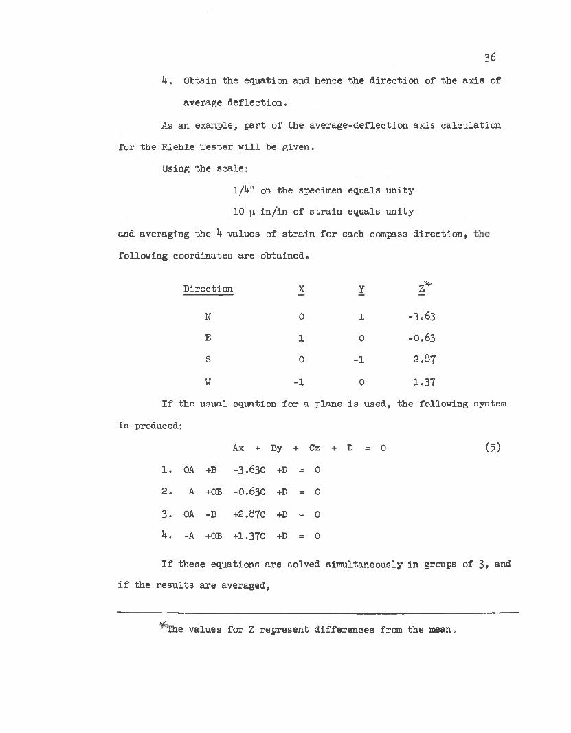
U. O btain th e eq u a tio n and hence th e d i r e c t io n o f th e a x is o f
average d e f le c t io n .
As an example, p a r t o f th e a v e ra g e -d e f le c t io n a x is c a lc u la t io n
fo r th e R ieh le T e s te r w i l l he g iv en .
Using th e sc a le :
1/ V on th e specimen equals u n ity
10 p, in / i n o f s t r a in equals u n ity
and av erag in g th e b values: o f s t r a i n f o r each compass d i r e c t io n ,
fo llo w in g co o rd in a tes a re o b ta in e d .
D ire c tio n X Y z *
N 0 1 -3 .6 3
E 1 0 - 0.63
S 0 -1 2 .87
W -1 0 1 .37
I f th e u su a l eq uation f o r a p lane i s used , th e fo llow ing system
i s produced:
D = 0 (5)Ax + By + Cz
1 . OA +B -3.630
0119
2 . A +0B -0.63C
0II9
3 . OA -B +2.87C +D = 0
b . -A +0B +1.37C
0119
I f th e se equations a re so lved sim u ltan eo u sly in groups o f 3 > and
i f th e r e s u l t s a re averaged .
vThe v a lu es fo r Z re p re se n t d if f e re n c e s from th e mean.v /
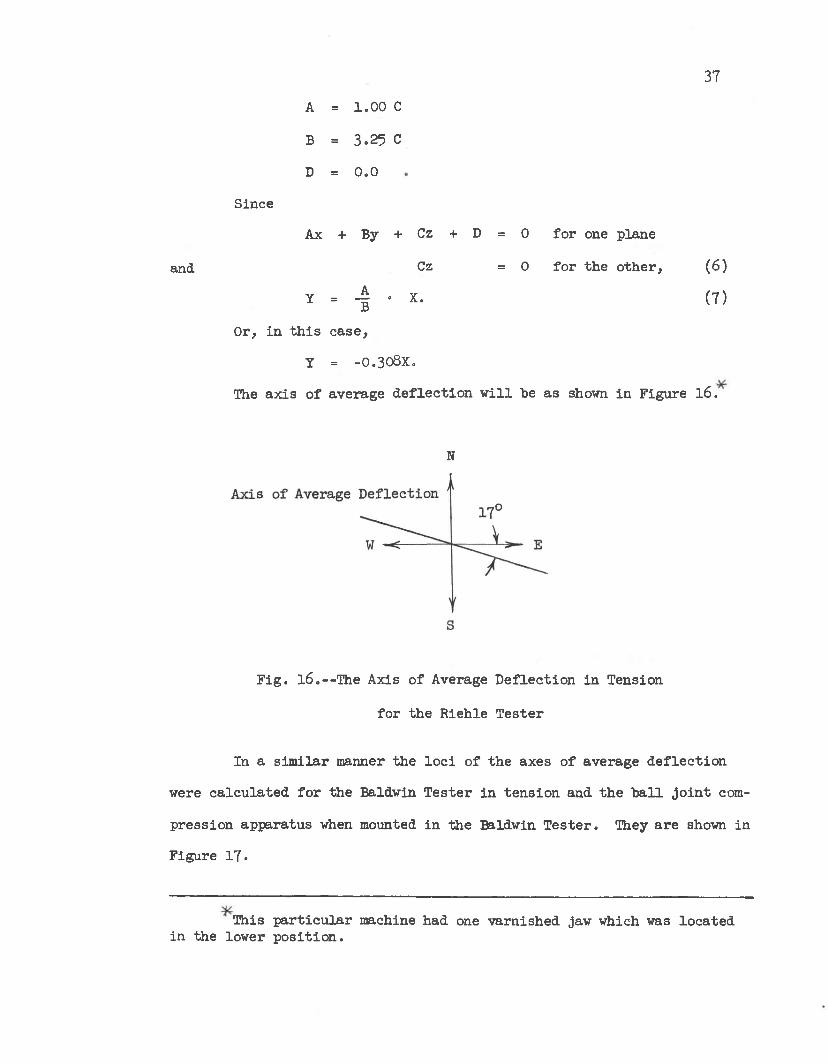
Since
37
A = 1 .00 C
B = 3 .25 C
D = 0 .0
Ax + By + Cz + D = 0 fo r one plane
and
Y = ± B
Or, in t h i s c a se .
Cz
• X.
= 0 fo r th e o th e r . (6 )
(7)
y = - 0 . 308X.
The a x is o f average d e f le c t io n w i l l he as shown in F igure l6 .
N
F ig . l 6 . —The Axis o f Average D e fle c tio n in Tension
fo r th e R ieh le T e s te r
In a s im ila r manner th e lo c i o f th e axes o f average d e f le c t io n
were c a lc u la te d fo r th e Baldwin T e s te r in te n s io n and th e h a l l j o i n t com
p re ss io n ap p ara tu s when mounted in th e Baldwin T e s te r . They a re shown in
F igure 17.
This p a r t i c u la r machine had one v a rn ish ed jaw which was lo c a te d in the low er p o s i t io n .

38
Com pression^ Tension
F ig . 1 7 .—Axes o f Average D e fle c tio n fo r th e
Small Baldwin T es tin g Machine.
,f >l<:The sc r ib e d l in e on th e com pression ap p ara tu s was on th e E ast s id e .
The w e ll- lu b r ic a te d b e a rin g b a l l s in th e com pression ap p ara tu s
should have p reven ted th e tra n sm iss io n o f any bending moment in to th e
com pression specim en. This would have been th e case i f th e b a l l s u r
faces were f r i c t i o n l e s s and i f th e c e n te rs o f th e b a l l s la y e x a c tly on
th e a x is o f th e specim en. A pparen tly , some e c c e n t r ic i ty d id e x i s t , and
a sm all amount o f bending was p re s e n t . For t h i s re a so n , th e a x is o f
average d e f le c t io n was c a lc u la te d f o r the b a l l j o i n t a p p a ra tu s .
I n te r p r e ta t io n o f th e Measurements
Some d i f f i c u l t y was encountered w ith th e s t r a in gages a t th e b e
g inn ing o f t h i s p ro je c t ; in c o n s is te n t r e s u l t s from one gage in s t a l l a t i o n
to th e n ex t f r u s t r a te d a l l a ttem p ts to make p re c ise m easurem ents. The
beh av io r o f u n fa m ilia r s t r e s s s t r a i n curves made p re c is e s t r a in in g o f
th e s t e e l specimens q u ite d i f f i c u l t .

39
A d e f in i te n o n - l in e a r i ty i s u s u a lly observed in th e f i r s t 150
m icro -inches p e r inch o f s t r a i n . A pparen tly , t h i s in accu racy i s caused
by th e f i n i t e th ic k n e ss o f th e cement la y e r under th e gage. Whenever a
h igh degree o f accu racy i s d e s ire d , an i n i t i a l read in g a t the 150 (j,
i n . / i n . le v e l may be made and t h i s amount i s th en s u b tra c te d from a l l
subsequent re a d in g s . C o rrec tio n i s u s u a lly made by s h i f t in g th e s t r e s s
s t r a in curve to cause i t to pass through th e o r ig in .
When th e y ie ld p o in ts* were being c a r e f u l ly m easured, some r a th e r
unusual beh av io r o f th e s t r e s s s t r a i n diagram was n o tic e d . When th e
t e s t in g machine was stopped a t th e t e n s i l e y ie ld p o in t , th e specimen
im m ediately unloaded to a p o in t approx im ate ly -j- o f th e way down th e
l in e a r p o rtio n o f th e s t r e s s - s t r a i n diagram . When th e machine was ag a in
tu rn ed on, th e specimen suddenly began to c reep u n c o n tro lla b ly a t a
n e a r ly co n s ta n t lo a d . T his y ie ld in g was q u ite re m in isc en t o f th e b e
h a v io r o f h o t g la ss or some o th e r supercoo led l iq u id . A rough sketch
o f t h i s b ehav io r i s shown in F igure 1 8 .
F ig . 1 8 .—The s t r e s s - s t r a i n diagram in th e
v i c in i t y o f th e y ie ld p o in t .
*The term " y ie ld p o in t" used in t h i s s tu d y was a r b i t r a r i l y d e fin ed as th e p ro p o r tio n a l l i m i t .

^0
The most lo g ic a l ex p lan a tio n fo r th e f i r s t phenomenon stems from
a c o n s id e ra tio n o f th e t e s t in g machine i t s e l f . As would he expected ,
th e machine i s h u i l t q u ite rug g ed ly , and th e sp rin g co n s ta n ts th ro u g h
out i t s s t ru c tu re a re h ig h . When th e specimen y ie ld s s l i g h t ly , th e
change in d e f le c t io n would cause an a p p re c ia b le change in load due to
th e h igh o v e ra l l sp rin g c o n s ta n t o f th e t e s t e r i t s e l f . A sp rin g c o n sta n t7
capable o f causing such an e f f e c t would have to be in th e o rd e r o f 10
l b s . / i n . This f ig u re i s q u ite r e a l i s t i c f o r a t e s t in g machine o f th i s
s i z e . This e f f e c t o f un load ing down th e e l a s t i c curve p robab ly has n o t
been n o tic e d b e fo re because du ring t e n s i l e t e s t s , i t i s u s u a lly unnec
e s s a ry to s to p th e machine w hile read in g s a re ta k en .
A c a r e fu l check o f o th e r s t r e s s - s t r a i n diagram s has shown th a t
th e o th e r phenomenon, th e u n c o n tro lla b le c reep im m ediately a f t e r y ie ld ,
i s q u ite common and was s a l i e n t because o f th e h igh s e n s i t i v i t y o f the
measurements being ta k en .
In te r p r e ta t io n o f th e R esu lts
Since th e law o f s t a t i c e q u ilib riu m must be s a t i s f i e d , every
r e s id u a l s t r e s s must be ba lanced by a s t r e s s o r group o f s t r e s s e s o f n e t
op p o site s ig n . A c tu a lly , i t i s th e fo rce s which must be b a lan ced , so
th e s t r e s s e s must be in te g ra te d over t h e i r a re a s o f in flu en c e b efo re
th e y may be p ro p e rly co n sid e red . F ig u re ih shows a preponderance o f
t e n s i l e s t r e s s (e s p e c ia l ly a t th e outboard edge) which i s p h y s ic a lly
im p o ssib le . The o n ly lo g ic a l e x p lan a tio n f o r t h i s phenomenon i s th a t
l i g h t t e n s i l e s t r e s s e s were s te a d i ly in tro d u ced through th e g rin d in g
p ro c e ss . O therw ise, th e p o s i t iv e a re a under th e curve would n e a r ly
equal th e n eg a tiv e a r e a .
h i
The s t r e s s curves fo r p o in t No. 3 , F igure 19B, show te n s i l e
s t r e s s e s a t th e c e n te r o f th e specimen and com pression n ear th e o u ts id e
as would be expected i f th e o u te r f ib e r s y ie ld e d f i r s t . I f t h i s s t r e s s
p a t te rn con tin u es to e x i s t and i f th e B auschinger e f f e c t con tinues to
e x i s t f o r specimens s t r a in e d to h ig h e r le v e ls o f te n s io n , th e evidence
may be co n sidered to be v e ry s tro n g th a t th e r e s id u a l s t r e s s e s a re th e
cause o f th e B auschinger e f f e c t . No conclusion can be drawn in t h i s case
because th e s t r a in s used were r e l a t i v e ly sm all compared w ith th e s t r a in
a t th e p o in t o f u ltim a te s t r e n g th . I f f u r th e r ex p erim en ta tio n a t p o in ts
o f much h ig h e r s t r a i n shows a d isappearance o f th e s t r e s s p a t te rn in
F ig u re 19B and a c o n tin u a tio n o f th e B auschinger e f f e c t , t h i s ex p lan a tio n
w i l l have been proven in v a l id .
F ig u re 19 a ls o shows a g re a te r p o s i t iv e a re a under th e cu rv e . A
sm a lle r a re a a t th e ou tboard s id e would be expected in a c i r c u la r s p e c i
men, b u t s in ce th e se specimens were f l a t t e n e d , equal a re a s would be ex
p e c te d . A gain, th e g re a te r p o s i t iv e a re a seems to in d ic a te th e in tro d u c
t io n o f t e n s i l e s t r e s s by g rin d in g .
F igu re 20B shows d e f in i te com pressive s t r e s s e s on th e in s id e and
t e n s i l e s t r e s s e s on th e o u ts id e o f th e com pression specim ens. This in
d ic a te s t h a t th e outerm ost f ib e r s were th e f i r s t to y ie ld due to th e
h ig h e r com pressive s t r e s s e s . As th e load was re le a s e d , th e p a r t i a l l y
unloaded o u te r f ib e r s were fo rced in to te n s io n by th e s t r a in r e la x a tio n
in th e r e s t o f th e specim en. These t e n s i l e s t r e s s e s a re balanced by the
com pressive s t r e s s n e a r th e c e n te r .
F igu re 2QA, th e p lo t fo r th e specimens o f p o in t No. k , shows the
same type o f s t r e s s p a t te r n , b u t n o t so v iv id ly . A lso , a su g g estio n o f
th e p o in t No. 3 p a t te rn i s a p p a re n t. I t may be concluded th a t a t t h i s
k2
p o in t th e t r a n s i t i o n ta k es p lace where th e t e n s i l e p a t te rn s d isap p ea r
and g ive way to th e com pressive p a t te r n s . A gain, as in a l l o f th e s t r e s s
p a t te r n s , th e b ia s o f th e t e n s i l e g rin d in g s t r e s s e s i s p re s e n t .
F ig u res 19A through 2GB must be accep ted w ith some re s e rv a tio n
because in each case th e s c a t t e r o f th e p rim ary curves was approx im ate ly
tw ice as severe as i t was in F igu re lU , Trends were in d ic a te d b u t no t
a s d e f in i t e ly as th e y were in th e case o f F igure lU .

STRE
SS
IN
RS.I.
X |
Q__
__
STRE
SS
IN
P.S.I.
^3
x 4 USED I OVERLAPPED
B. POINT NO. 3
FIG. J 9 . RESIDUAL S T R E S S P A T T E R N FOR T E N SIL E SPE C IM E N S

STRE
SS
IN
PSI
kb
* ' A 5. USED 2 OVERLAPPEDA. POINT NO. 4 ° _ 4 U SE D 2 OVERLAPPED
4 U SE D_ I OVERLAPPED0
B. POINT NO. 5FIG. 2 0 . RESIDUA!_ _ S T R E S S PA T T E R N F O R ‘..COMPRESSION SPE C IM E N S.

CHAPTER V
CONCLUSIONS AND RECOMMENDATIONS
Conclusions
The in fo rm atio n gained from th e specimens s t r a in e d on ly in te n s io n
was n o t c o n c lu s iv e , b u t th e p o in t No. 3 d a ta showed a s t r e s s p a t te rn which
seemed to su p p o rt th e "Bauschinger e f f e c t from re s id u a l s t r e s s " th e o ry .
These specimens which were p u lle d to th e h ig h e s t t e n s i l e s t r a i n showed
th a t y ie ld in g does occur f i r s t in th e o u te r f ib e r s and th a t th e se p a r
t i a l l y unloaded f ib e r s a re pushed in to com pression a s th e e x te rn a l lo ad
i s removed.
The same type o f phenomenon occurred in th e com pressive specim ens.
The h ig h e r - s tr e s s e d o u te r f ib e r s y ie ld e d f i r s t and th en were fo rced in to
te n s io n a s th e com pressive e x te rn a l lo ad was re le a s e d . A gain, th e e f f e c t
was more pronounced in th e more h ig h ly s t r a in e d specim ens. In bo th i n
s ta n c e s , i t does seem th a t th e B auschinger e f f e c t i s caused by re s id u a l
s t r e s s . Repeated p la s t i c s t r a in in g o f s t e e l in one d ir e c t io n would cause
r e s id u a l s t r e s s e s which would ten d to r a is e th e y ie ld p o in t , b u t t h i s i s
an in s u f f i c i e n t cause f o r work h a rd en in g .
This work must be con tinued w ith p o in ts o f much h ig h e r s t r a in b e
fo re a firm conclusion may be drawn concerning th e v a l id i t y o f th e th e o ry
th a t th e B auschinger e f f e c t i s caused by r e s id u a l s t r e s s e s .
45

Re c ommendati ons
h6
Since d i f f i c u l t y was encountered w ith th e Buda B-12 cement immed
i a t e l y a f t e r y ie ld , i t i s recommended th a t th e u t i l i t y o f some o f th e h igh
e lo n g a tio n cements he in v e s t ig a te d . The Budd Co. produces a h igh e lo n g a
t io n cement k i t d e s ig n a ted GA-1. Inc luded in t h i s k i t i s a p l a s t i c i s e r
which should s ig n i f i c a n t ly improve th e b ehav io r o f th e cement a t h igh
s t r a i n s . I t i s suggested th a t th e h igh e lo n g a tio n cement he t r i e d w ith
th e s tan d a rd epoxy gages a s w e ll as th e h igh e lo n g a tio n (p o s t y ie ld )
ty p e s . Perhaps t h i s method o f i n s t a l l a t i o n w i l l extend th e u se fu ln e ss o f
th e s tan d a rd g a g es .
When a paper gage i s cemented w ith Duco, th e gage and cement w i l l
u s u a lly s ta y i n ta c t a t e lo n g a tio n s as h ig h as 25,000 y, i n . / i n ^ I t would
he d e s ire a h le to check th e l i n e a r i t y o f th e se h ig h ly - s tr a in e d gages a g a in s t
some new ones. I f l i n e a r i t y s t i l l e x i s t s , i t may he p o ss ib le to use th e se
gages ag a in fo r th e com pression phase o f th e t e s t , th u s e lim in a tin g th e
need fo r i n s t a l l a t i o n o f new g a g es»
The in s t ru c t io n s f o r s t r e s s g rin d in g p r in te d by th e G eneral Motors
Corp. recommend u s in g a Norton type 32A^6-H8VBE g rin d in g wheel f o r t h i s
purpose . The Norton c a ta lo g may n o t l i s t a wheel o f t h i s type la rg e
enough to he used on th e a v a i la b le g r in d e r . However, an e q u iv a len t wheel
can e a s i ly he found. L arger d iam eter g rin d in g wheels a re recommended b e
cause o f th e le s s freq u e n t wheel d re s s in g n e ce ssa ry . O ther advantages
a re l i s t e d in C hapter I I I .
A ll th re e o f th e ty pes o f s t e e l t e s t e d showed th e B auschinger
e f f e c t . Any one o f them, th e 1018, 10^5 o r 11V* i s recommended fo r t h i s
type o f re s e a rc h .
^ T h is s t r a in i s w e ll w ith in th e work harden ing reg io n o f th e 1018s t e e l u sed .

b7
While th e lo ad in g o f th e specimens i s ta k in g p la c e , th e s t r e s s -
s t r a in diagram should he p lo t te d a s th e d a ta i s m easured. This procedure
w i l l enab le th e o p e ra to r to more c lo s e ly fo llow th e p ro g ress o f th e
t e s t . As th e d a ta i s b e ing m easured, th e t e s t in g machine should be op er
a te d q u ite slow ly , bu t w ith o u t s to p p in g . When th e machine i s s topped ,
th e specimen ten d s to unload s l i g h t l y and in c o n s is ta n c ie s r e s u l t in th e
s t r e s s and s t r a i n d a ta .
D uring th e c u t t in g o f th e beams from th e specim ens, c a re fu l
m achining w ith l i g h t c u ts cannot be over-em phasized. In t h i s s tu d y , the
s id e s o f th e beams were ground in an a ttem p t to remove th e s t r e s s e s
caused by m achining.
When th e specimens a re s t r a in e d to th e v a rio u s p o in ts on th e
s t r e s s - s t r a i n diagram , i t would be advantageous to t r y pure com pression
on a few o f them fo r com parison p u rp o se s .
A curve f i t t i n g tech n iq u e u t i l i z i n g a method o th e r th an th a t o f
th e l e a s t squares should be t r i e d as an a ttem p t to smooth th e s t r e s s
p a t te rn s which a re g iven as o u tpu t by th e program . A nother p o s s ib i l i t y
would be to modify th e program so th a t th e curve f i t t i n g may be done
g ra p h ic a l ly by th e u se r so th a t th e f i t t e d curve may be m anually in p u t to
the computer

BIBLIOGRAPHY
1 . M artin , D. E. "E valuation o f Methods f o r Measurement o f R esidua lS t r e s s ," S o c ie ty o f Automotive Engineers TR-ll+7, September 1957.
2 . G u re rra , Carmin, "R esidual S tre s s G rin d in g ." L abora to ry Procedure,Used by th e ME-1 Department o f th e Research L ab o ra to rie s D iv is io n o f G eneral Motors C o rp o ra tio n . (V e rifa x e d .)
3 . Sm ith, S . L. and Wood, W. A. " In te rn a l S tre s s Caused by P la s t icFlow in M ild S te e l ," P roceedings o f th e Royal S o c ie ty o f London, l82:UoU-UlU, l p l T
*+. Wooley, R. L. "Bauschinger E f fe c t in Some Face-C entered and Body- C entered Cubic M eta ls ." P h ilo so p h ic a l Magazine, 1+1+:597-6 l8 ,Ju n e , 1953*
5* Naghdi, P. M., E ssenburg , F . , and K off, W. "An E xperim ental Study o f I n i t i a l and Subsequent Y ie ld S urfaces in P l a s t i c i t y , "Jo u rn a l o f A pplied M echanics, 25:201-209, June, 1958*
6 . C o t t r e l l , A. H. D is lo c a tio n s and P la s t ic Flow in C ry s ta ls (OxfordU n iv e rs ity P re s s , London, 1956).
7 . Handelman, G. H. and W arner, W. H. "Loading Paths and th e In c re m ental S tr a in Law," Jo u rn a l o f M athematics and P h y sics ,33:157-161+, 195^.
8 . Bridgeman, P. W. "The S tre s s D is tr ib u t io n a t th e Neck o f a TensionSpecim en," T ran sac tio n s o f th e American S o c ie ty f o r M eta ls ,3 2 :5 5 3 -5 7 U ,1 ^ i¥ :
9 . S hanley , F . R. "T en sile I n s t a b i l i t y (Necking) o f D u c tile M a te r ia ls ,"Aerospace E n g in eerin g , 20:30-31> December, 1961 .
10 . Nunes, John . "F lo w -S tre ss -S tra in R e la tio n sh ip in Tension T estso f S te e l ," M a te ria ls R esearch and S tan d a rd s , 3 No. 9 :719-722, Septem ber, 1963 .
11. P rag e r, W. "The Theory o f P l a s t i c i t y - A Study o f R ecent A chievem ents," Proceedings o f th e I n s t i t u t i o n o f M echanical E n g in eers ,169: I n - 57 , 1955.
12. V a sile v , A. M. "M icro s tre sses C reated in M etals During P la s t icD eform ation I I , " S o v ie t Physics o f S o lid S ta te , 1 , No. 11: 1586-1595, i 960 .
1+8

k9
13• H e ten y i, M. I . ( e d .) Handbook o f E xperim ental S tre s s A n a ly sis ,(John W iley and Sons, I n c . , New York, 1950),~ p . 5 l 8 .
14. Todd, Henry S. "R esidual S tre s s D is tr ib u t io n Changes During DynamicU n id ire c tio n a l T e n s ile Loading." Unpublished M as te r 's T h es is , Brigham Young U n iv e rs ity , Provo, U tah, I 96U.
15 . L e tn e r, H arold R. "A p p lica tio n o f O p tic a l In te r fe re n c e to th eStudy o f R esidua l S urface S tr e s s e s ," P roceedings o f th e S o c ie ty f o r E xperim ental S tre s s A n a ly s is , 10 No. 2 :2 3 -3 ^ , 1953*

APPENDIX A
EQUATIONS FOR RESIDUAL STRESS
The a lg e b ra ic ex p ress io n s fo r r e s id u a l s t r e s s a s d e riv ed by-
H arold R. L etner (15) have been review ed by th e a u th o r . The ab rid g ed
form i s p re sen te d a s fo llo w s: Let F igu re 21 re p re se n t th e c ro ss s e c tio n
o f a beam which i s caused to assume a c e r ta in c u rv a tu re , C, by i t s
r e s id u a l s t r e s s e s .
F ig . 2 1 .--Schem atic R ep resen ta tio n o f R esid u a l S tre s s
D is tr ib u t io n in an U n restra in ed B ar.
When th e beam i s c o n s tra in e d to l i e f l a t by th e a p p l ic a t io n o f
e x te rn a l moments, th e s t r e s s a t Z th en becomes cr' (z ) as shown in F igure
22. I f , w hile the b a r i s h e ld s t r a ig h t , s t r e s s e d su rfa ce la y e rs a re
removed by g r in d in g , th e le n g th o f th e beam w i l l change, g iv in g r i s e to
a uniform change a (w) in th e a x ia l s t r e s s th roughout th e th ic k n e ss of
th e rem ain ing m a te r ia l (see F igure 2 2b ). Now, th e s t r e s s a t any le v e l
z i s eq u al to th e o r ig in a l s t r e s s <j' (z ) p lu s a new s t r e s s a (w) r e s u l t
in g from th e change in le n g th (see F igu re 2 2 c ).
50

51
I f th e r e s t r a in in g e x te rn a l to rq u es a re re le a s e d th e specimen w i l l
bend to i t s e q u ilib riu m cu rv a tu re C(w) and in so doing w i l l s e t up an
a x ia l s t r e s s which can be deduced from F igure 21 . The a x ia l s t r a i n a t
le v e l z in th e b a r i s :
[R(w) + ( | - z ) ] &9 - R(w)d0 /W ^R(w)d0 = R(w) ^2 ” Z
where R(w) i s th e ra d iu s o f c u rv a tu re .
The correspond ing s t r e s s i s ob ta in ed as fo llo w s:
u s in g th e b a s ic beam equation
1 _ M_" R ‘ E l
M = CEI
Me= T
(8 )
(9)
( 10 )
s u b s t i tu t in g th e ex p ress io n s f o r M and c , th e moment re le a s e
s t r e s s i s o b ta in ed .
CT = C (w )E (| - z ) . (1 1 )
By adding th e o r ig in a l s t r e s s , th e le n g th change s t r e s s and th e
moment r e le a s e s t r e s s , t h e t o t a l s t r e s s i s o b ta in ed .
a (z ,w ) = a ' ( z ) + d(w) + C(w) E ( | - z ) . (12)
A pplying th e co n d itio n s o f s t a t i c e q u ilib riu m y ie ld s th e fo llo w
in g ex p ress io n fo r th e r e s id u a l s t r e s s which e x is te d a t any le v e l , z , b e
fo re any la y e r s were removed:

52
3 ( 3 , w0 ) = ^ ^ + ^ [ c (z ) - c (wo )]
w - z E r wo+ - y - E C(wQ) - j J z C(a)dz ( 13 )
where C (wq ) I s th e e q u ilib riu m c u rv a tu re b e fo re any la y e r s were removed
and C(z) th e e q u ilib riu m c u rv a tu re when th e beam th ic k n e ss had been r e
duced to w = z .

53
a. Jo.
Z Z
<S (Z,W) = s \ z ) + g(W) + C(W)E ( j - - z )
FIG. 22 .(a ). STRESS DISTRIBUTION WHEN THE BAR IS HELD STRAIGHT.(b ) . STRESS CAUSED BY THE CHANGE IN LENGTH RESULTING
FROM THE REMOVAL OF THE SURFACE LAYERS.
(c ) . STRESS DISTRIBUTION AFTER THE REMOVAL OF THESURFACE LAYERS BUT BEFORE THE BAR IS ALLOWED TO BEND.
(<J). STRESS CAUSED BY THE BENDING OF THE BAR TO ITS EQUILIBRIUM CURVATURE.
(e ) . STRESS DISTRIBUTION IN THE UNRESTRAINED BAR AFTER THE REMOVAL OF THE SURFACE LAYERS.

5U
FIG. 2 3 . GEOMETRICAL QUANTITIES NECESSARY FOR THE CALCULATION OF AXIAL STRAIN IN A BAR BENT TO A UNIFO RM C U R VA TU R E .

APPENDIX B
RESIDUAL STRESS GRINDING
By Cannin G u rre ra , Shop T echnician At Request o f J . 0 . Almen (2)
Forward
In r e s id u a l s t r e s s g rin d in g o f th e O.D. and I .D . o f a r in g or f l a t s u r fa c e s , th e co n d itio n o f th e wheel and depth o f c u t w i l l determ ine w hether s t r e s s e s w i l l be im parted onto th e su rfa ce o r n o t by g r in d in g .For s a t i s f a c to r y r e s u l t s , th e wheel must be k ep t c lea n and sh arp , (emphasis on sh a rp ) , and th e depth o f c u t must be d r a s t i c a l l y reduced from co n v en tio n a l g rin d in g p ra c t ic e fo r th e l a s t few thousand ths inch o f s to ck to be removed.
The fo llo w in g d e sc rib e s th e procedure o f s t r e s s g rin d in g as p ra c tic e d by th e ME-1 Department o f th e R esearch L ab o ra to rie s D iv is io n o f G eneral Motors C orpo ra tion fo r r e s id u a l s t r e s s a n a ly s is .
Procedure
F la t su rfa c e s (su rfa c e g r in d e r) :
Let us say , fo r example, th a t a .030 inch la y e r has to be ground o f f to some p redeterm ined dim ension. F i r s t , d re s s th e w heel. Proceed to remove th e f i r s t .020 inch in th e somewhat co n v en tio n a l manner o f .001 to .0015 inch depth o f c u t , depending upon th e s iz e o f th e work specim en. But a t no tim e s h a l l th e su rfa ce become d is c o lo re d o r o v erh ea ted to such an e x te n t a s to make i t unbearab le to to u ch .
The rem aining .010 inch la y e r should be removed a s fo llo w s:
D ress w heel; remove .005 inch la y e r w ith c u ts .0003 inch deep ." " " .003 " " " " .0002 " "
" " " .002 " " " " .0001 "
For rem oval o f la y e r s o f .010 inch th ic k o r l e s s , proceed as o u tlin e d above.
The above schedule i s based on experim en ta l work done on s t e e l specimens o f 50 Roc hardness w ith a su rfa ce a re a o f approx im ate ly 2 sq . i n . (3A " x 3")* A f te r making f iv e com plete passes over th e specimen
55

56
w ith c u ts o f .0001 inch deep (.0005 inch t o t a l th ic k n e ss o f la y e r r e moved), th e wheel re q u ire d re d re s s in g . For p ro p o r t io n a l ly la r g e r a r e a s , say 10 s q . i n . (5" x 2" ) , th e wheel would re q u ire d re s s in g a f t e r one com plete pass w ith a c u t o f .0001 inch deep .
I t must he borne in mind th a t ex trem ely l i g h t c u ts w i l l ten d to d u l l th e wheel sooner th an h e a v ie r c u t s , th e r e f o r e , th e o p e ra to r must be v e ry observ ing in d e te c t in g prem ature d u l l in g o f th e w heel, g e n e ra lly seen as a b r ig h t o r g la r in g su rfa ce f i n i s h .
The ta b le t r a v e l r a te shou ld be medium, a lthough a f a s t e r r a te i s p re fe r re d over a slow er t r a v e l . The slow er r a te w i l l quicken wheel d u l ln e s s .
Cross feed o f th e work i s g e n e ra l ly from .015 to .020 inch p e r p a s s . For specimens .010 to .020 inch th ic k , i t re q u ire d g re a te r c a u tio n .
C onsecutive c u ts (down feed o f th e w heel) a re made a f t e r each f u l l coverage o f th e wheel over th e work i s made. No sp ark in g ou t i s n e ce ssa ry excep t f o r th e v e ry f i n a l c u t , i f d e s ire d , fo r a smoother f i n i s h .
G rind ing Wheel:
To d re ss th e w heel, c u ts o f .001 inch deep w ith a sharp diamond a re found to be most s a t i s f a c to r y .
The diamond should be ra p id ly passed under th e wheel in o rd e r to produce a f r e e c u t t in g w heel. A fte r making th e l a s t pass w ith a .001 inch depth c u t , do n o t rep ass th e diamond under th e wheel b e fo re c le a r in g th e wheel from th e diamond; o therw ise th e diamond w i l l on ly d u l l th e shaii) edges o f th e a b ra s iv e g ra in s on th e face o f th e w heel.
The p o in t o f th e diamond should be on c e n te r l in e o f th e wheel and th e n ib t i l t e d in th e same d i r e c t io n a s th e r o ta t io n o f th e w heel.The t i l t o r d rag ang le should be 10° - 15° from th e v e r t i c a l .
The wheel i s o f th e medium s o f t ty p e , w ith a v i t r i f i e d bonded No. k6 s iz e g ra in , and o f medium s t r u c tu r e . I t i s m anufactured by th e Norton Company and i s la b e le d 32A^6 -H8vBE. Symbol 32A s tan d s f o r Alundum a b ra s iv e ; No. k6 g ra in s iz e (medium); H grade ( s o f t ) ; No. 8 s t ru c tu re (medium sp ac in g ); V bond ( v i t r i f i e d ) ; and BE f o r type o f bond.
The w idth o f th e wheel i s l / k inch in s te a d o f th e con v en tio n a l l /2 " w idth to reduce d ra g . The range o f wheel speed i s 3300-3500 rpm.A ll work i s ground d ry .
O.D. G rind ing :
The same r a te o f s to ck rem oval as o u tlin e d f o r su rfa ce g rin d in g i s recommended, whenever p o ss ib le to ap p ly , depending upon th e s iz e o f th e work, r i g i d i t y o f th e work, and m achine. G enera l p ra c t ic e i s to p r a c t i c a l ly spark out b e fo re ap p ly in g a d d i t io n a l in - fe e d o f th e wheel to th e work.
57
Not much though t o r concern i s given as to w hether to g rin d wet o r d ry , s in ce th e depth o f th e cu ts a re ve ry l i g h t .
On th e two u n iv e rs a l g rin d in g machines used fo r s t r e s s g r in d in g , one employs a l /2 " x 12" wheel a t 1700-1800 rpm and th e o th e r has a l /2 " x 10" wheel running a t 2600-2700 rpm.
Again on ly about 1 fk" w idth (by d re s s in g ) o f th e •wheel i s used fo r both m achines. The grade o f both wheels i s p r a c t i c a l ly th e same as fo r th e su rfa ce g r in d e r , 32AM$-l8VBE.
I .D . G rind ing :
E x ac tly th e same recommendations and s p e c if ic a t io n s as th o se fo r O.D. g r in d in g , except th a t th e wheel speeds used a re as recommended by th e m anufactu rer.
The depth o f c u ts w i l l v a ry w ith th e s iz e o f work, r i g i d i t y o f th e q u i l l , and m achine, e t c . , in v a r ia b ly le s s th an th ose s p e c if ie d fo r su rfa ce g rin d in g .

58
APPENDIX C
OUTLINE OF THE STRESS CALCULATION FRCGRAM
1 . Read in th e t i t l e , re g u la r p o in t d a ta .
2 . Compute th e c o rre c te d cu rv a tu re fo r r e g u la r d a ta .
3 . Read in th e in v e r te d d a ta .
b. Compute th e c o rre c te d c u rv a tu re fo r th e in v e r te d d a ta .
5 . Compute th e c u t t in g d is ta n c e .
6 . P r in t ou t th e c a lc u la te d d a ta .
7 . Read in th e modulus o f e l a s t i c i t y end in s t ru c t io n s fo r th e
p lo t te d cu rve .
8 . I n i t i a l i z e th e curve f i t t i n g eq u a tio n c o u n te r .
9 . Read in th e no . o f eq u a tio n o rders used and eq u a tio n o rd e rs .
10. Compute th e curve f i t t i n g m a tr ix .
11. In v e r t th e computed m a trix .
12. W rite out th e computed fu n c tio n s .
13. Compute th e d is ta n c e and f i t t e d c u rv a tu re e q u a tio n s .
lU . W rite out th e computed fu n c tio n s .
15. C alcu la te th e mean s t r e s s f o r th e second cu t s t r e s s com putation.
16. Compute th e o r ig in a l s t r e s s v e rsu s th e d is ta n c e below th e specimen
s u r f a c e .
17. W rite out th e computed fu n c tio n s .

APPENDIX D
A LISTING OF THE MODIFIED STRESS
CALCULATION PROGRAM

n n
r>
n n
n
n n
n
no
n
no
n n
o
C R E S I D U A L S T R E S S DATA A N A L Y S I S 0 0 1 0C 0 0 2 0
D I ME NS I ON T ( 3 0 ) * 0 ( 3 0 ) » G ( I O . I O ) . 0 0 3 0I C C R V E C 5 C ) . C C U R V E ( 5 0 ) • C L R V E K S O ) , C I S T ( 5 i > , S ( 5 0 ) . 0 1 ( 1 2 ) . 0 0 4 02 i H I C K ( 5 0 ) 0 0 5 0
C DI ME N S I ON T ( 3 0 ) . D ( 3 0 ) . X ( 3 0 ) . H ( 1 0 ) , G ( I O . I O ) , G I V < 2 0 . 2 0 > . A ( 2 0 ) . 0 0 6 01C U R V E ( 5 0 ) * C C U R V E i S C ) . C L R V E K S O ) , C I S T ( 5 C ) » S ( 5 0 ) » D I U 2 ) , C( 3 0 ) , 0 0 7 02 T H I C K ( 5 0 ) 0 0 8 0
CCMMCN/ SAMEVGI V ( 2 0 , 2 0 ) , H ( 2 0 ) » MP1 . N P , C ( 3 0 ) . X ( 3 0 ) . A ( 2 0 )
READ DATA I C E N I F I C A T I C N CARD AND D I S E C T I N CUT NUMBER
5 0 READ < 5 . 1 0 ( D M I ) . I - 1 . 1 2 )I C FORMAT ( 1 2 A6 >
READ ( 5 . 1 4 ) NCL T « CC 1 4 FORMAT ( 15 / ( E 1 5 . C ) )
READ I H I C KN E S S AND CURVATURE DI S T ANCE - OUT S I DE OF S P ECI MEN UP
READ ( 6 . 1 1 ) N RP » ( T ( l > , D ( I ) . I = 1 . N R P )I I FORMAT ( 15 / ( 1 2 F 6 . 0 ) )
COMPUTE CORRECTED CURVATURE
DC I 0 0 1 = 1 , N R PICC C < I > 2 . 0 * D ( I ) + CC / 1 ( 1 ) * « 2
READ N O . OF DATA PCI NT 5 TAKEN WITH S P ECI MEN I NVERTED
REAC < 5 . 1 2 ) M P 1 2 FORMA 1 ( 1 5 )
NP = NRP + N I P N R P 1 = NRP + 1
READ DATA P O I N T S TAKEN WI TH S PECI MEN I NVERTED
0 0 9 0 0 1 0 0 ouo 0 1 2 0 0 1 3 0 0 1 4 0 0 1 5 0 0160 0 1 7 0 0 1 8 0 0 1 9 0 0 2 0 0 0 2 1 0 0 2 2 0 0 2 3 0 0 2 4 0 0 2 5 0 0 2 6 0 0 2 7 0 0 2 8 0 0 2 9 0 0 3 0 0 0 3 1 0 0 3 2 0 0 3 3 0 0 3 4 0 0 3 5 0 OnO

no
n
no
n
no
n
no
n
no
n
nn
READ (5*13) C T ( I ) « D(I), I = NRP1, NP ) 036013 FOR MAT ( 12F6.0 ) 0370
C 0380COMPOTE CORRECTED CURVATURE 0390
04C0DO 110 I = NRP1i NP 0410
110 C (I ) = 2.0* D ( I ) - CC / T { I ) «* 2 04200430
COMPUTATION OF CUTTING CISTANCE 04400450
DO 120 I = 1, NP 0460120 X (I ) = TCI) - TCI) 0470
0480PRINT OUT CALCULATED DATA 0490
0500fcRITE(6*1) NCUT * CC 0502
1 FORMAT C/ 2 9 X 6HNCUT = 13* 5X 4HCC = E15.5 /) 0503fcR I TE (6*15)01 * ( I, TCI), XCI), DCI), CCI). 1=1,NP ) 0510
15 FORMAT!// 29X 12A6 /// 21X 1HI 18X 4HTCI) 16X 4HXCI) 16X 4HDCI) 0520116 X 4 H C ( I )//( 17 X 15. 5 X 4F20.8 )) 0530
0540READ IN MODULUS OF ELASTICITY, NO. OF PLOTING POINTS AND INTERVAL 0550
0560READ (5,16)N P P , XINT, E 0570
16 FORMAT! I5.2F15.0 ) 05800590
READ ORIGINAL SPECIMEN THICKNESS VALUE 06000610
READ ( 5 ,13)CRIGT 06200630
INITIALIZE CURVE FITTING ECUAT ION COUNTER 06400650
ICOUNT = 1 0660C 0670 o,C READ NO. OF EG. ORDERS USED AND EQUATION ORDER 0680 HC 0690

r, n
REAC ( 5 . 1 2 I N M 1 3 C READ ( E . 1 2 ) N
MPl = M + 1CC COMPUTATI ON CF CURVE F I T T I N G MATRIX
DO 1 3 2 J = 1 . MPl1 3 1 H { J ) = 0 . 0
DC 1 3 2 K = 1 . MP11 3 2 G ( J » K ) w o * c
DO 1 3 7 J = i » MPlDO 1 3 7 I = l . NPIF(J-l) 135. 133. 135
133 H{J) = H (J ) + C ( I )GO TO 1351
135 H (J ) = H (J ) + C (I ) * X(I) ** (J-l)1351 CONTINUE
DO 137 K = 1, MPl IF(J + K— 2) 136. 1353. 136
1353 G (J »K ) = G(J,K) + 1.GO TO 137
136 G(J,K> = G(J.K) + X(I) ** (J+K-2)137 CONTINUE
DC 140 J = 1 ,MPl A(J) = H(J)DC 140 K = I .MPl
1 4 C GIV(J.K) = G(J.K)
INVERT COMPUTED MATRIX
DO 150 J = 1. MP1WRITE (6,18)J , H (J ) , ( G(J,K),
18 F O R M A T (/1 OX 3HJ =. 12.( 11E 12.4) )15 C CONTINUE
CALL MAT INV
0 7 0 00 7 1 00 7 2 00 7 3 00 7 4 00 7 5 00 7 6 00 7 7 0 0 7 8 0 0 7 9 0 0 8 0 0 0 8 1 0 0 8 1 2 0 8 1 4 0 8 1 6 0 8 2 0 0 8 2 5 0 8 3 0 0 8 3 2 0 8 3 4 0 8 3 6 0 8 4 0 0 8 5 0 0 8 6 0 0 8 7 0 0 8 8 0 0 8 9 0 0 9 0 0 0 9 1 0 0 9 2 01 000
K = l , MP 1 ) 1 0 1 01 0201 0 3 0 CJ\ro0 9 3 00 9 4 0

no
n
o
Ccccc
3 5 CC
WR I TE OUT C C MPU TED FUNCTI ONS
COMPUTATI ON CF DI S T A N C E AND F I T T E D CURVATURE F UNCTI ONS
DO 3 5 0 1 = 1 , NPP C U R V E ! I ) = 0 . 0 D C U R V E ( I ) = 0 . 0 CUR VE 1 ( 1 ) = 0 . 0D I S T ( I ) = T H I C K ( I ) = DO 3 5 0 J = CUR V E ( I ) = D C U R V E ( I ) = C U R V E I ( I ) = CONTI NUE
FLCA T ( I ) CRI GT - 1 , MP1 C U R V E ( I )
DCURVE(
* X I NT D 1 S T ( I )
+ I )
CURVE I ( I )
A ( J ) * DI S T ( I ) * * { J - l )+ F L O A T ( J —1 ) * A ( J ) » D 1 S T ( I ) **+ A ( J ) * D 1 S T ( I ) ** J / F L OA T ( J )
( J - 2 )
WRITE OUT COMPUTED FUNCTI ONS
WRITE ( 6 , 2 0 ) 0 1 , N P P , M, Z , E , C R I G T , ( I , D I S T ( I ) , THII C K ( I ) , D C U R V E ( I ) , CUR V E ( I ) • C U R V E I ( I ) , 1 = 1 , N P P )
2 0 FORMAT( / / 1 0 X 1 2 A 6 , / / / 1 0 X 6 HNPP = , 1 4 , 10X 4HM = , 1 4 , 10X1 3HZ = E 1 5 . 6 . 1 0 X 3HE = E 1 2 . 5 , 10X 7HCRI GT = F 1 0 . 7 , / / 1 0 X 1HI2 1 1 X 7 H D I S T ( I ) 1 2 X 8 H T H I C K ( I ) 1 1 X 9HDCURVE ( I ) 1 2 X 8 H C U R V E ( I ) 1 1 X3 9 HCURVE 1 ( 1 ) / ( / 8 X 1 3 . 5 F 2 0 . 8 ) )
I F ( NCUT - 1 ) 9 9 8 . 4 0 0 , 4 5 09 9 8 WRITE ( 6 . 2 1 )
2 1 F OR MA T ! 1 0 X 4 3 HCAL L E D E X I T AT 9 9 8 DUE TO ERROR CONDI TI ON )CALL E XI T
CCALCULATI ON CF MEAN S T R E S S FOR 2ND CUT S T R E S S COMPUTATI ON
4 0 0 CF I N A L CF I N I DO 4 1 0 C F I N A L
= 0.0 = 0 . 0 J = 1 , MP1= C F I N A L + A ( J ) * X( NP) ** ( J - I )
0 9 5 0 0 9 6 0 1 1 8 0 1 1 9 0 I 200 1 2 1 0 1 2 2 0 1 2 3 0 1 2 4 0 1 2 5 0 1 2 6 0 1 2 7 0 1 2 8 0 1 2 9 0 1 3 0 0 1 3 1 0 1 3 2 0 1 3 3 0 1 3 4 0 I 3 5 0 1 3 6 0 1 3 7 0 1 3 8 0 1 3 9 0 1 4 0 0 1 4 1 0 1 4 2 0 1 4 3 0 1 4 4 0 1 4 5 0 1 4 6 0 1 4 7 0 1 4 8 0 1 4 8 2 1 4 8 4 1 4 8 6
CNLO
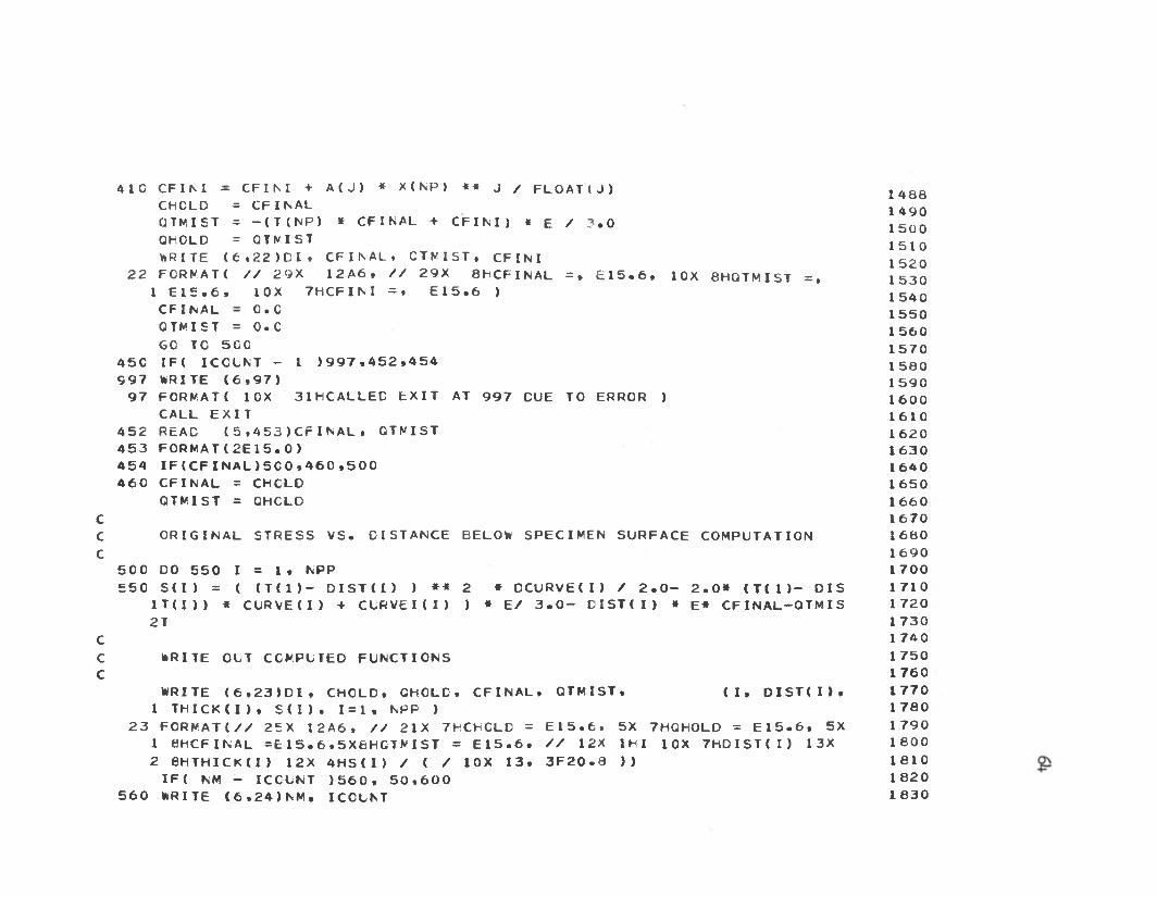
u u
4 1 0 CF I N I - C F I M + A ( J ) * X ( N P ) * * J / F L O A T ( J ) 1 4 8 8CHCLD = C F I N A L 1 4 9 0OTMI ST = —( T ( N P ) * CFI NAL + C F I M ) « E / 3 . 0 l 5 0 0QHOLD = OTMI ST l 5 1 QWRITE < 6 , 2 2 > D I . C F I N A L . CT V 1 S T . C F I M l 5 2 0
2 2 FORMAT! / / 2 9 X 1 2 A 6 , / / 2 9 X 8 HC F I N A L = , E 1 5 . 6 , 10X 8 HQTMI S T = , i 5 3 01 E 1 5 . 6 , 1 0 X 7 H C F I N I = . E 1 5 . 6 ) 1 5 4 0
CF I N A L — 0 • C 1 5 5 0OTMI ST = O. C l 5 6 06 0 TO 5 C 0 1 5 7 0
4 5 C I F ( I COLNT - 1 > 9 9 7 . 4 5 2 . 4 5 4 1 5 8 09 9 7 WR I TE ( 6 . 9 7 ) l 5 g 0
9 7 FORMAT( 10X 3 1 HCALLED E X I T AT 9 9 7 CUE TO ERROR ) 1 6 0 0CALL E X I T 1 6 1 0
4 5 2 READ ( 5 , 4 5 3 ) C F I N A L , OTMI ST 1 6 2 o4 5 3 F O R M A T ( 2 E 1 5 . 0 ) 1 6 3 04 5 4 I F ( C F I N A L ) 5 C 0 » 4 6 C » 5 0 0 1 6 4 04 6 0 CF I N A L = CHCLD 1 6 5 0
OTMI ST = QHCLD 1 6 6 0C 1 6 7 0C ORI GI N A L S T R E S S V S . DI S T ANCE BELOW S PECI MEN SURFACE COMPUTATI ON 1 6 8 0C 1 6 9 0
5 C 0 DO 5 5 0 1 = 1 . NPP 1 7 0 05 5 0 S ( I ) = ( ( T ( 1 ) — D I S T ( I ) ) * * 2 * D C U R V E ( I ) / 2 . 0 - 2 . 0 * ( T ( l > - D I S 1 7 1 0
1 T ( I ) ) * C U R V E ( I ) + CURVE 1 ( 1 ) ) * E / 3 . 0 - D I S T ( I ) * E* C F I N A L —QTMI S 1 7 2 02 T 1 7 3 0
C 1 7 4 0WRITE OUT COMPUTED F U NCT I ONS 1 7 5 0
1 7 6 0WRITE ( 6 . 2 3 ) D I , CHOLD, CHCLD. C F I N A L , OT MI S T , ( I , O I S T ( I ) , 1 7 7 0
1 T H I C K ( I ) , S ( I ) . 1 = 1 , NPP ) 1 7 8 02 3 F O R M A T ! / / 2 5 X 1 2 A 6 , / / 2 1 X 7HCHCLD = E 1 5 . 6 . 5X 7 HQH0LD = E 1 5 . 6 , 5X 1 7 9 0
1 8 HC F I N A L = E 1 5 . 6 . S X 6 H C T M I S T = E 1 5 . 6 . / / 12X I H I 1 0 X 7 H D I S T ( I ) 1 3 X 1 8 0 02 8 H T H I C K ( I ) 1 2 X 4 H S ( I ) / ( / 1 0 X 1 3 . 3 F 2 0 . 8 ) ) 1 8 1 0
I F ( NM - I CCUNT ) 5 6 0 , 5 0 . 6 0 0 1 8 2 05 6 0 WRITE ( 6 » 2 4 ) NM » I CCUNT 1 8 3 0

n n
2 4 FORMAT ( 1CX 4HNK = , 1 5 .1 5 5 0 . >
CALL EXI T
8H I COUNT = , 1 5 . 5X 2 1 H E R R 0 R CONDI TI ON AT 1 8 4 0 1 8 5 0 1 8 6 0 1 8 7 0 I 8 8 0 1 8 9 0
6 0 0 I CCLNT = I CCLNT + 1GO TC 1 3 0 END
$ I B F T C MATI NV L I S T C MATRIX S OLUTI ON CF L I N E A R EQUATI ONS
1 SUBROUTI NE MATI NVM A 0 0 2 0M A 0 0 4 0
2 COMMON/ S AME/ A( 2 0 . 2 0 ) . B ( 2 0 ) . N . K . Y ( 3 0 ) . X ( 3 0 ) . C ( 2 0 )3 M1=N4 M2 =N+15 D 0 6 1 = 1 . Ml6 A ( I , M 2 ) = B ( I )
DC 4 0 J = 1 . Ml4 0 1 k R I T E ( 6 . 4 1 ) ( A ( J , I ) . 1 = 1 , M 2 )4 1 FORMAT( 1 H + . 1 0 F 1 3 . 5 )
*R I TE ( 6 , 4 2 ) N . M 1 . M2 . K . M4 2 FORMAT ( 1 H + . 5 I 6 )5 2 DO 6 0 1 1 = 1 . Ml53 L 1=1+15 4 DO 6 0 J = L 1 . M25 5 SOL = A ( I , J ) / A ( I , I )5 6 I F ( S O L ) 5 8 . 6 0 , 5 85 8 DO 5 9 L = J , M 2
A t J , L ) = A ( J . L ) - A ( I , L ) * S C L5 9 W R I T E ( 6 . 4 3 ) I . J . A ( J . L ) • S O L • A ( I , L )4 3 FORMAT! 1 5 X . I 3 , I 3 . 3 F 1 5 . 3 )6C CONTI NUE
6 0 1 CONTI NUE6 1 DO 6 8 1 = 1 , Ml6 2 L 3 = M 2 —I6 3 S L M = C • 06 4 I F { 1 - 1 ) 6 8 , 6 8 , 6 5

6 5 L 2 = F l - I + 26 6 DO 6 7 L = L 2 * FI6 7 S U M = S U F 4 C ( L ) * A ( L 3 , L >
* R I T E ( 6 , 4 3 ) L 3 * L » SUF *C ( L ) » A ( L3 » L )6 8 C ( L 3 ) = ( A ( L 3 , F 2 ) - S U F ) / A ( L 3 . L 3 )
C CO ERROR ANC VALUE CCFP1 6 8 S U F = C . C
6 9 VkRI T E ( 6 , 7 0 ) (C ( I ) , 1 = 1 , M7 0 F C R F A T ( 5 X , 1 8 H C C E F . OF CURVE F I T / 5 X , 1 OE1 2 . 7 )7 1 CO 7 9 1 = 1 , K7 2 F E X = 0 . 07 3 DC 7 5 J = I » N7 4 L = N + 2 —J7 5 F E X = ( F E X + C ( L ) ) * X ( I )7 6 F E X = F E X + C ( 1 )7 7 ERR = Y ( I ) —FE X7 8 S UF= S UM+ ERR* ERR7 9 V n R I T E ( 6 . 1 3 0 ) X ( I ) , Y ( I ) . F E X . E R R
13C F O R F A T ( 6 X » 2 H X . 9 X , 1 0 H F E A S . C U R V . , 7 X , 1 OHCALC, CURV. , 4 X , 5 HERR0R 1 / 4 E 1 5 . 7 )
3 2 6 DE V = 13 2 7 D E V = ( S Q R T { S U F ) / D E V )3 2 8 V k R I T E ( 6 » 1 1 8 ) D E V1 1 8 F 0 R F A T ( 1 H + , 1 0 X , E 1 1 , 5 )
8 3 RETURN 8 1 END
SENTRY
85

APPENDIX E
SAMPLE INPUT SHEET AND EXPLANATION

SAMPLE OF I NP LT DATA 1
1 2 . 5 E — 71 3
. 1 5 1 . 0 0 0 5 . 1 3 4 . 0 0 0 0 . 1 3 1 - . 0 0 0 5 . 1 2 0
. 0 8 6 - . 0 0 3 0 . 0 7 6 - . 0 0 2 0 . 0 6 5 - . 0 0 6 0 . 0 5 4
. 0 3 0 - . 0 3 0 03
. 0 5 4 - . 0 1 0 . 0 4 4 - . 0 1 8 0 . 0 3 0 - . 0 3 12 4 C . 0 0 5 0 2 9 5 C 0 0 0 0 •
. 1 5 114
P OI NT N O . 1 CONTROLS SECOND SAMPLE1
o • o
13. 1 9 4 0 . 0 0 0 0 . 1 8 3 8 . 0 0 0 0 . 1 6 7 7 - . 0 0 0 1 . 1 4 9 9 -. 1 0 1 3 - . 0 0 0 7 . 0 8 5 2 - . 0 0 0 9 . 0 6 9 6 - . 0 0 1 4 . 0 4 8 6 - . 0 2 8 3 - . 0 0 5 9
C
3 4 C . 0 0 5. 1 9 4 0
1 3 234
2 9 5 0 0 0 0 0
NCUTCCNRP
. 0 0 0 0 . 1 0 9 . 0 0 0 0 . 0 9 8 - . 0 0 0 5 T . D 1 - 6
. 0 1 0 0 . 0 4 4 - . 0 1 7 5 . 0 3 5 - . 0 2 1 0 T . D 7 - 1 2T . D 1 3N I PD . T 1 4 - 1 6 NPP I NTE OR IGT NM = 1
M = 4
CUT = 1 CC = 0 NRP
. 0 0 0 2 . 1 3 3 0 - . 0 0 0 3 . 1 1 7 6 - . 0 0 0 5
. 0 0 2 2 . 0 3 8 0 - . 0 0 3 3 . 0 3 3 6 - . 0 0 3 8
N I P = 0 BLANCK NPP I NTE OR IGT NM=i NM=3 M=2 M = 3 M=4
8

APPENDIX F
DATA ORDER AND FORMAT DESCRIPTION
A d e s c r ip t io n o f th e symbols used in th e program as re c e iv e d
from Henry S. Todd ( l^ ) i s given as fo llo w s:
Data I d e n t i f i c a t io n Card See Symbol Table D ire c to ry
Specimen Cut Number P lace f ix e d p o in t number 1 o r two in column 5 (Format 15)
C o rrec tio n C o e ff ic ie n t I f you tak e measurements o f d e f le c t io n on bo th s id e s o f th e specimen du rin g th e g rin d in g procedure t h i s c o e f f ic ie n t i s unnecessary . Use zero i f t h i s i s th e c a se . I f n o t , 12 .5 tim es 10"? i s p robab ly a s good as any . (See sample d a ta . )
NRP E n te r h e re (Format 15) th e number o f d a ta p o in ts to be used in th e s e c t io n th a t fo llo w s . I f CC = 0 , I would su g g est th a t a l l your d a ta be p u t in t h i s s e c tio n s im ila r to specimen l 6 SP, c u t 1 on sample d a ta s h e e t .
Thickness and D e fle c tio n D istance Here i s where th e Thickness andd e f le c t io n d a ta go. Each card w i l l
NIP
handle 72 c h a ra c te rs in th e form of 12 s ix c h a ra c te r f i e l d s . P lace specimen th ic k n e ss f i r s t and th en i t s measured d e f le c t io n from th e cu rv a tu re guage.
I f you use a zero c o rre c t io n co e f f i c i e n t (CC = 0 ) , p lace a zero a ls o in column 5 h e re and p lace a b lank card a f t e r t h i s one.
Data Taken in in v e r te d p o s it io n
NPP INTE This ca rd co n ta in s th re e f i e ld s w ith th re e b i t s o f in fo rm a tio n .
69
NPP INTE

TO
F i r s t , (NPP) i s th e number o f r e s u l ta n t c a lc u la te d p o in ts to be p lo t te d . N ext, (INT) i s th e i n t e r v a l used between each c a lc u la te d s t r e s s and d e f le c t io n v a lu e . L a s t ly , (E) i s th e modulus o f e l a s t i c i t y .The card f i e ld s a re : 1 s t , a f iv e c h a ra c te r f ix e d p o in t f i e l d fo r NPP, and 2nd, two 15 c h a ra c te r f lo a t in g p o in t f i e ld s fo r INT and E. (ORIGT - NPP*INT should equal th ic k n e ss o f specimen a t tim e change from 1s t c u t to second i s made. )
ORIGT O rig in a l o r f i r s t value o f th ic k n e ss to be used in p lo t t in g th e r e s u l t s a t o u tp u t. (F 6 .0)
NM See Symbol D ire c to ry (Format 15)
M See Symbol D ire c to ry (Format 15) I f NM is la r g e r than one, th e program w i l l look fo r a d d i t io n a l curve f i t t i n g o rd e r cards a f t e r t h i s on e . The c a lc u la t io n s made on th e second c u t d a ta uses cu rv a tu re d a ta from th e f i r s t c u t . I t i s th e re fo re imp o r ta n t th a t th e curve f i t t i n g o rder t h a t you f e e l i s b e s t be p laced l a s t i f more th an one i s to be u sed . There i s a p ro v is io n b u i l t in to th e program whereby second c u t inform at io n can be p rocessed in d ependen tly o f f i r s t c u t d a ta , b u t I h a v n 't found occasion to use i t y e t .
CFI QTM CFI s tan d s fo r CFINAL and QTM re p re se n ts Q sub t minus S sub t . I t i s w ith t h i s card th a t p ro v is io n fo r p ro cess in g 2nd c u t d a ta independe n t ly o f f i r s t c u t d a ta i s p rovided f o r . D iis card must appear a f t e r th e f i r s t curve f i t t i n g o rd e r (m) ca rd in each 2nd c u t d a ta s e t . I f m u ltip le curve f i t t i n g o rders a re u sed , th e r e s t fo llo w t h i s c a rd .In p ro cess in g in th e s tan d a rd manner where f i n a l cu rv a tu re va lues from th e f i r s t c u t a re used w ith th e se c ond, p lace f lo a t in g p o in t zeros in each o f th e se 15 c h a ra c te r f i e l d s .
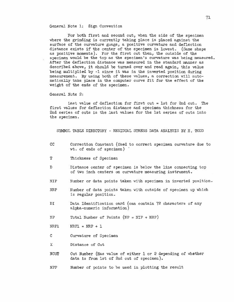
G eneral Note 1: Sign Convention
For both f i r s t and second c u t , when th e s id e o f th e specimen where th e g rin d in g i s c u r r e n t ly ta k in g p lace i s p laced a g a in s t th e su rfa ce o f th e cu rv a tu re guage, a p o s i t iv e c u rv a tu re and d e f le c t io n d is ta n c e e x is t s i f th e c e n te r o f th e specimen i s lo w e st. (Same shape as p o s i t iv e moments). For th e f i r s t c u t th e n , th e o u ts id e o f th e specimen would be th e to p as th e specim en 's c u rv a tu re was b e in g measured A f te r th e d e f le c t io n d is ta n c e was measured in th e s tan d a rd manner as d e sc rib e d above, i t shou ld be tu rn e d over and read a g a in , t h i s value b e ing m u lt ip l ie d by -1 s in ce i t was in th e in v e r te d p o s i t io n d u ring measurem ent. By u sin g bo th o f th e se v a lu e s , a c o r re c t io n w i l l a u to m a tic a l ly tak e p lace in th e computer curve f i t fo r th e e f f e c t o f th e w eight o f th e ends o f th e specim en.
G eneral Note 2:
L ast va lue o f d e f le c t io n f o r f i r s t c u t = 1 s t fo r 2nd c u t . The f i r s t v a lues fo r d e f le c t io n d is ta n c e and specimen th ic k n e ss fo r th e 2nd s e r ie s o f c u ts i s th e l a s t v a lu es f o r th e 1 s t s e r ie s o f c u ts in to th e specim en.
SYMBOL TABLE DIRECTORY - RESIDUAL STRESS DATA ANALYSIS BY H. TODD
cc C o rrec tio n C onstant (Used to c o r re c t specimen cu rv a tu re due to w t. o f ends o f specim en)
T Thickness o f Specimen
D D istance c e n te r o f specimen i s below th e l in e connecting to p o f two inch c e n te rs on c u rv a tu re m easuring in s tru m e n t.
NIP Number o r d a ta p o in ts tak en w ith specimen in in v e r te d p o s i t io n .
NRP Number o f d a ta p o in ts taken w ith o u ts id e o f specimen up which i s re g u la r p o s i t io n .
DI Data I d e n t i f i c a t io n card (can c o n ta in 72 c h a ra c te rs o f any alpha-num eric in fo rm atio n )
NP T o ta l Number o f P o in ts (NP = NIP + NRP)
NRP1 NRP1 = NRP + 1
C C urvature o f Specimen
X D istance o f Cut
NCUT Cut Number (Has value o f e i th e r 1 o r 2 depending o f w hether d a ta i s from 1 s t o f 2nd c u t o f specim en).
NPP Number o f p o in ts to be used in p lo t t in g th e r e s u l t

XINT
E
CURV
THICK
M
NM
H
Z
DIST
DCURVE
CURVEI
CFINAL
ORIGT
72
I n te r v a l between p lo t t in g th ic k n e sse s
Modulus o f E la s t ic i ty -
Curve f i t t e d C urvature
Curve f i t t e d Specimen Thickness
Order o f Curve F i t t i n g Polynom ial
Number o f Curve F i t t i n g Polynom ials to be used
Summation Location (See F o r tra n Program)
A Measure o f th e accu racy o f th e curve f i t to th e o r ig in a l d a ta
Cut D istance used in p lo t t in g f i t t e d cu rv a tu re v s . X
dC/dX%CdX
CURVE (NPP)
O rig in a l Thickness o f Specimen

RESIDUAL STRESSES AND THE
BAUSCHINGER EFFECT
An A b stra c t o f a T hesis
Subm itted to th e M echanical E ng ineering Department
Brigham Young U n iv e rs ity
Provo, Utah
In P a r t i a l F u lf i l lm e n t
Of th e Requirem ents f o r th e Degree o f
M aster o f Science
■by
Raymond M. Huebner
Ju n e , 1965

ABSTRACT
The prim ary o b je c tiv e was to f in d th e r e s id u a l s t r e s s p a t te rn in
a p l a s t i c a l l y deformed b a r in an a ttem p t to r e l a t e t h i s s t r e s s p a t te rn
to th e B auschinger e f f e c t . S te e l specimens were p l a s t i c a l l y deformed in
te n s io n and com pression and then analyzed fo r r e s id u a l s t r e s s by the
beam d is s e c t io n method. P re lim in ary work was done to e s ta b l i s h r e s id u a l
s t r e s s g rin d in g tech n iques f o r fu tu re re s e a rc h .
The problem o f bending f i e ld s in th e t e n s i l e t e s t i n g machines was
c a r e f u l ly in v e s t ig a te d and c o r re c t iv e m easures were ta k e n . A p iece o f
ap p a ra tu s u t i l i z i n g tw in b a l l jo in t s was designed to minimize th e bending
d u rin g com pression and th e lo c i o f th e axes o f average d e f le c t io n were
c a lc u la te d f o r a l l o f th e s i tu a t io n s encoun tered .
A specimen c o n fig u ra tio n was designed which would ex p ed ite th e s t r e s s
g rin d in g procedure and f u l f i l l th e o th e r requ irem en ts o f th e s tu d y . Lab
o ra to ry te ch n iq u es , i . e . , s t r a i n gage i n s t a l l a t i o n , s t r a i n m easurem ents,
and g rin d in g procedures were in v e s t ig a te d and d is c u s s e d . V a ria tio n s in
s t e e l type and machines used were t r i e d in a search f o r advantageous com
b in a tio n s .
I t was found th a t y ie ld in g f i r s t occu rred in th e outerm ost f ib e r s
o f bo th th e t e n s i l e and com pressive specim ens. The s t r e s s p a t te rn s
found sup p o rt th e id ea t h a t th e B auschinger e f f e c t cou ld be caused by
r e s id u a l s t r e s s e s . No d e f in i t e co nclusions were reached because o f th e
l im ite d amount o f d a ta m easured and because o f s c a t t e r in th e c a lc u la te d
s t r e s s p a t t e r n s .
Improved methods fo r s tu d y in g t h i s problem a re recommended.
1

APPROVED