
Residual Stress and Critical Crack Size before and after ... and after PWHT to assess residual...
6
Residual Stresses 2016: ICRS-10 Materials Research Forum LLC Materials Research Proceedings 2 (2016) 603-608 doi: http://dx.doi.org/10.21741/9781945291173-102 Content from this work may be used under the terms of the Creative Commons Attribution 3.0 license. Any further distribution of this work must maintain attribution to the author(s) and the title of the work, journal citation and DOI. Published under license by Materials Research Forum LLC. 603 Residual Stress and Critical Crack Size before and after Post- Weld Heat-Treatment Law M 1 , Paradowska 2 * A, Hoye N 3 , Grace P 4 1, 2 ANSTO, Locked Bag 2001, Kirrawee DC NSW 2232, Australia 3 University of Wollongong, Northfields Ave, Wollongong NSW 2522, Australia 4 Jemena, 99 Walker St, North Sydney NSW 2060, Australia 1 [email protected], 2 [email protected], 3 [email protected], 4 [email protected] Keywords: Welding, Neutrons, Residual Stress, PWHT Abstract. Post-weld heat-treatment (PWHT) is performed to reduce residual stress, but is not always possible to perform. The residual stresses on a thick section weld on a gas pipeline were determined before and after PWHT to assess residual stress and critical defect sizes. Introduction Many essential pipeline modifications and repairs require welding. Codes mandate the use of PWHT above some thickness which varies depending on which code is followed [1]. Unfortunately, product flow within the pipeline carries away the heat necessary for PWHT and many pipelines cannot be shut down or depressurized, thus making PWHT impossible. The major reason for the use of PWHT is to avoid HACC (also known as cold cracking, or delayed cracking) which principally occurs in ferritic steels, most often during or a short time after welding. HACC is a risk only for a short period (approximately 1 day): once this period is past and the weld has been subject to delayed NDT, HACC is no longer a threat and any defect which is detected is subject to a failure assessment by a conventional defect assessment method. Material and sample characterisation The X70 grade spherical tee (1143mm OD x 41mm thickness) halves were placed around the run pipe, the halves welded together, then welded to a X60 grade run pipe (508mm OD x 8.5 mm thickness). The welding was carried out with water flowing through the run pipe to simulate the heat sink of the flowing product. After the residual stresses were measured, the sample was subject to a furnace PWHT and the measurements were repeated. Figure 1 Weld identification in the spherical tee hot-tap junction.
Transcript of Residual Stress and Critical Crack Size before and after ... and after PWHT to assess residual...

Residual Stresses 2016: ICRS-10 Materials Research Forum LLC Materials Research Proceedings 2 (2016) 603-608 doi: http://dx.doi.org/10.21741/9781945291173-102
Content from this work may be used under the terms of the Creative Commons Attribution 3.0 license. Any further distribution of this work must maintain attribution to the author(s) and the title of the work, journal citation and DOI. Published under license by Materials Research Forum LLC.
603
Residual Stress and Critical Crack Size before and after Post-Weld Heat-Treatment
Law M1, Paradowska2* A, Hoye N3, Grace P4 1, 2ANSTO, Locked Bag 2001, Kirrawee DC NSW 2232, Australia
3University of Wollongong, Northfields Ave, Wollongong NSW 2522, Australia 4Jemena, 99 Walker St, North Sydney NSW 2060, Australia
[email protected], [email protected], [email protected], [email protected]
Keywords: Welding, Neutrons, Residual Stress, PWHT
Abstract. Post-weld heat-treatment (PWHT) is performed to reduce residual stress, but is not always possible to perform. The residual stresses on a thick section weld on a gas pipeline were determined before and after PWHT to assess residual stress and critical defect sizes.
Introduction Many essential pipeline modifications and repairs require welding. Codes mandate the use of PWHT above some thickness which varies depending on which code is followed [1]. Unfortunately, product flow within the pipeline carries away the heat necessary for PWHT and many pipelines cannot be shut down or depressurized, thus making PWHT impossible. The major reason for the use of PWHT is to avoid HACC (also known as cold cracking, or delayed cracking) which principally occurs in ferritic steels, most often during or a short time after welding. HACC is a risk only for a short period (approximately 1 day): once this period is past and the weld has been subject to delayed NDT, HACC is no longer a threat and any defect which is detected is subject to a failure assessment by a conventional defect assessment method.
Material and sample characterisation The X70 grade spherical tee (1143mm OD x 41mm thickness) halves were placed around the run
pipe, the halves welded together, then welded to a X60 grade run pipe (508mm OD x 8.5 mm thickness). The welding was carried out with water flowing through the run pipe to simulate the heat sink of the flowing product. After the residual stresses were measured, the sample was subject to a furnace PWHT and the measurements were repeated.
Figure 1 Weld identification in the spherical tee hot-tap junction.

Residual Stresses 2016: ICRS-10 Materials Research Forum LLC Materials Research Proceedings 2 (2016) 603-608 doi: http://dx.doi.org/10.21741/9781945291173-102
604
As the entire tee could not be measured by neutron diffraction, a representative section containing the critical start and end of the welds was cut from the tee hot-tap junction. Finite element modelling was carried out determine a sample size which would not affect the residual stress values. A model was made of the main butt weld between the half spheres (the branch pipe was ignored) and pseudo stresses were introduced by Chill Modeling [2] (figure 2). The spherical tee was then reduced in size to assess the effect on the residual stresses. These pseudo-stresses do not represent the actual residual stresses but can assess any effects due to change of restraint from specimen cutting.
Figure 2. Maximum stresses in full model (only one quarter is shown for clarity) and cut sample
When stresses are measured along the weld, the area near the cut end (left end of figure 3) shows
a large reduction in stresses. Measurements more than 68 mm (~2 thicknesses) away from the cut end will be within 5% of the un-cut values. Measurements closer to the runpipe will be affected less.
Figure 3. Stress results superimposed on cut model, with % difference between the uncut and cut stresses also shown.
Residual stress measurements The residual stress measurements were performed on the Kowari strain scanning instrument [3] at ANSTO. Since the basic principles of this technique are well known [4,5,6] only details specific to this measurement will be reported. A nominal gauge volume of 3x3x4 mm3 was used. Stress-free reference measurements were performed on slices 8mm thick slices. The errors in residual stress measurements were estimated to be ± 20 MPa.
Residual Stresses 2016: ICRS-10 Materials Research Forum LLC Materials Research Proceedings 2 (2016) 603-608 doi: http://dx.doi.org/10.21741/9781945291173-102
605
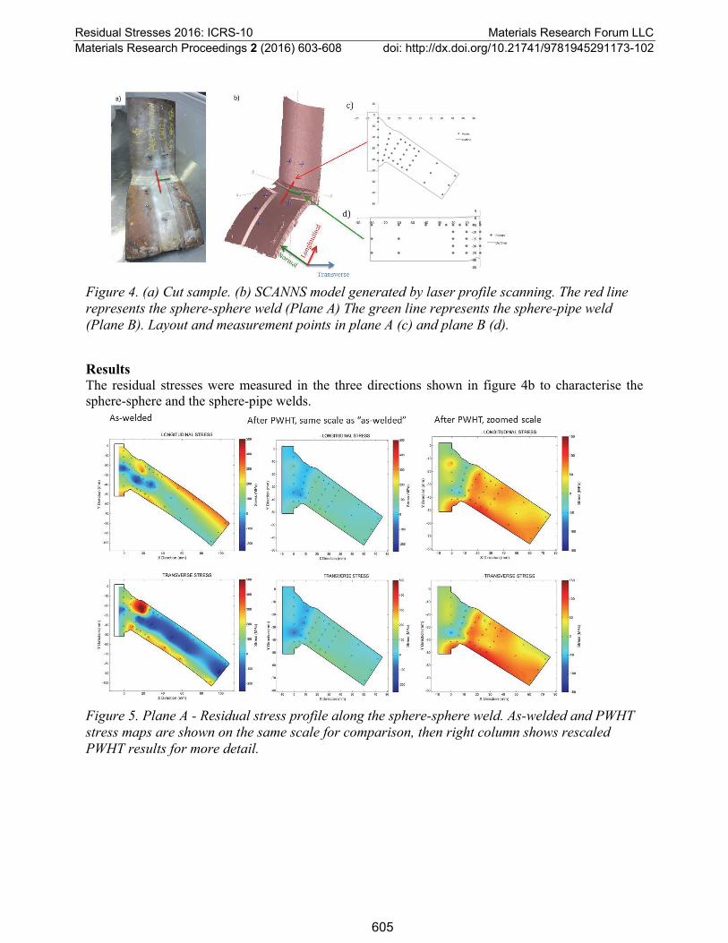
Figure 4. (a) Cut sample. (b) SCANNS model generated by laser profile scanning. The red line represents the sphere-sphere weld (Plane A) The green line represents the sphere-pipe weld (Plane B). Layout and measurement points in plane A (c) and plane B (d).
Results The residual stresses were measured in the three directions shown in figure 4b to characterise the sphere-sphere and the sphere-pipe welds.
Figure 5. Plane A - Residual stress profile along the sphere-sphere weld. As-welded and PWHT stress maps are shown on the same scale for comparison, then right column shows rescaled PWHT results for more detail.

Residual Stresses 2016: ICRS-10 Materials Research Forum LLC Materials Research Proceedings 2 (2016) 603-608 doi: http://dx.doi.org/10.21741/9781945291173-102
606
Figure 6. Plane B- Residual stress distribution along the sphere-pipe weld before and after PWHT (x=0 weld centre) the white area was not measured. As-welded and PWHT stress maps are shown on the same scale for comparison, then right column shows rescaled PWHT results for more detail.
The as-welded residual stresses were generally low, but approached the yield strength at one
position. Through-thickness residual stress maps across the butt weld at the weld intersection (Figures 5, 6) shows relatively high residual, the largest residual stress was 10 mm below the surface. These as-welded residual stresses were lower than code-based estimates, except at the weld intersection, where the stresses approached code-based estimates. After PWHT the residual stresses were reduced to less than 30% of the as-welded values.
Structural integrity assessment of welds based on measured residual stresses The critical defect depth for assumed inner wall defects 100 mm long were calculated using the R6 British Nuclear code [7]. To allow comparisons, the same stresses were assumed for both welds of 147 MPa membrane and 281 MPa bending. The weld was assumed to equal the sphere X70 tensile properties (485 MPa SMYS and 565 MPa SMTS) with a Charpy toughness of 40J.
The residual stress values are either code-based estimates or the measurements in this paper. Fitness for purpose assessments codes assume residual stresses either at yield, or some other distribution through-wall (Figure 7). In this work the BS 7910 Annex Q estimate was used for the as-welded, and the constant 110 MPa line was used in PWHT cases. Two sets of measured values were used, the low values in most positions in the weld (‘Typical’, Figure 7a) and the localised high values at the intersection of the 2 welds (‘Intersection’, Figure 7b). The ‘typical’ transverse residual stresses were lower than BS7910 estimate for high heat input welds. However, the residual stresses at the intersection of the two welds were higher than this code estimate at one point at the inner wall (Figure 7b).

Residual Stresses 2016: ICRS-10 Materials Research Forum LLC Materials Research Proceedings 2 (2016) 603-608 doi: http://dx.doi.org/10.21741/9781945291173-102
607
Figure 7. Residual stresses in sphere-sphere weld. a) typical. b) at weld intersection.
The critical crack depths for 100mm long defects were calculated (figure 8). PWHT increased the
allowable depth by 60% for ‘typical’ locations (with low residual stress), but only 20% for the results at the weld intersection which had higher residual stresses. The use of measured residual stresses increased the critical crack depth by 15 to 30% over code-based residual stress estimates.
Figure 8. Critical crack depth for 100 mm long defect in typical weld and at weld intersection.
|

Residual Stresses 2016: ICRS-10 Materials Research Forum LLC Materials Research Proceedings 2 (2016) 603-608 doi: http://dx.doi.org/10.21741/9781945291173-102
608
Conclusions The main findings are:
Residual stresses were highest at the weld toes and the weld root, and at the weld-weld
intersection.
All bar one residual stresses measurement was lower than code-based estimates.
PWHT reduced the residual stress, which increased the critical defect size.
In all cases the use of measured residual stresses increased the critical crack depth.
References
[1] Abson DJ et.al. “A review of postweld heat treatment code exemption - Part 1” Welding Journal, v.85, n.3, March 2006, pp.63-69
[2] Law M, Kirstein O, Luzin V ”An assessment of the effect of cutting welded samples on residual stress measurements by Chill Modelling” Journal of Strain Analysis for Engineering Design, V 45, Number 8 / 2010, pp 567-573
[3] O. Kirstein,V. Luzin, Materials Australia, Vol 41, 2008, 52-54
[4] Allen A, Hutchings MT, Windsor CG, Andreani C, "Neutron diffraction methods for the study of residual stress fields," Adv. Phys. 34, 445-473, 1985. https://doi.org/10.1080/00018738500101791
[5] Measurement of Residual and Applied Stress Using Neutron Diffraction, eds. M. T. Hutchings and A. D. Krawitz; NATO ASI Series 216E, Kluwer Academic Publishers, Dordrecht / Boston / London, 1992.
[6] Prask H.J, Brand PC "Residual Stress Determination by Means of Neutron Diffraction,", in Neutrons in Research and Industry, Proc. of Int. Conf. on Neutrons in Research and Industry, ed: G. Vourvopoulos, SPIE Proceedings Series, Vol. 2867, pp. 106-115 (1997). https://doi.org/10.1117/12.267879
[7] R6: Assessment of the Integrity of Structures Containing Defects, British Energy Generation Report R/H/R6, Revision 4, 2001


