Research Report 529 CONCRETE PAVEMENTS 1 2 3 …
23
Research Report 529 CRACKING IN CONCRETE PAVEMENTS by 1 Robert C. Deen Assistant Director James H. Havens 2 Director . 3 Assaf S. Rahal Research Engineer Chief and 4 W. Vernon Alevedo Research Engineer Senior Division of Research Bureau of Highways DEPARTMENT OF TRANSPORTATION Commonwealth of Kentucky Accepted for Publication by the American Society of Civil Engineers October 1979
Transcript of Research Report 529 CONCRETE PAVEMENTS 1 2 3 …

Research Report 529
CRACKING IN CONCRETE PAVEMENTS
by
1 Robert C. Deen
Assistant Director
James H. Havens 2 Director
. 3 Assaf S. Rahal
Research Engineer Chief
and
4 W. Vernon Alevedo
Research Engineer Senior
Division of Research Bureau of Highways
DEPARTMENT OF TRANSPORTATION Commonwealth of Kentucky
Accepted for Publication
by the American Society of Civil Engineers
October 1979

CRACKING IN CONCRETE PAVEMENTS
By Robert C. Deen 1, F. ASCE, James H. Havens2, M. ASCE,
Assaf S. Raha13, and W. Vernon Azevedo4
(Reviewed by the Highway Division)
l
INTRODUCTI ON
Cracking of portland cement concrete pavements is a common, even expected,
occurrence. To minimize potentially detrimental effects, it is necessary to understand
mechanisms that might be used to explain such behavior so that measures may be
developed and implemented to control the occurrence of such cracking. Several "theories"
are discussed that might provide the mechanisms of pavement cracking. An alternate
meachanism, based on fatigue loading of the concrete by temperature
expansions-contrations, for the development of so-called D-cracking is offered.
CRACK I NG OF PLA I N AND
JOINTED CONCRETE PAVEMENTS
Cracking of plain concrete pavements occurs when contraction or distension creates
forces equal to the compressive or tensile strengths of the concrete. For example, very
young pavement concrete may crack during the first drying (and) or cooling, if the
conditions are critical. The resisting forces are due to friction between the pavement and
earth. According to the frictional drag theory,
where
F = fW, 1
F = longitudinal drag force,
f = coefficient of friction between the pavement and earth (usually equal
to unity), and
W normal force (or weight of pavement).
W may be represented by an element of the body of height D and width w, having a
length L, multiplied by the density (unit weight), 'Ym• of the material. The force, F, may
be represented by the product of stress, a, and cross-sectional area, A; and A may be
defined as the product of D and w. Thus,
a x D x w = 'Ym x D x w x L x f 2
and

2
a 'Ym x L, 3
where f is taken as unity. For cracking to occur, a must be critical. Let acr equal the
modulus of rupture of the concrete -- say 600 psi (4.1 MPa); assume the density of the
concrete to be 144 lbs/ft3, or 0.0833 lbs/in3 (9.5 Mg/m3). Finally,
L "" 600 lineal feet (183 m). 4
It is seen that the tensile strength of the concrete in pounds per square inch is equal
to the length of pavement in feet which can be mobilized (brought into traction) in both
directions about an assumed point (cross section) of reference during contraction. The
natural interval between tension cracks, therefore, will be approximately 2L. There would
be at least one crack in each 1,200-feet (365-m) length of pavement. Usually, critical
drying-shrinkage or cooling occurs before the concrete achieves ultimate strength. For
instance, if new concrete achieves 30 psi (0.2 MPa) tensile strength during the first few
hours and undergoes further drying and cooling at night, there may be cracks at 60-foot
(18-m) intervals. This is a basis for spacing contraction joints at 50 feet (15 m) or less
and for sawing joints before the concrete is 16 hours old. Figure 1 shows a shrinkage
crack which was well controlled by a sawed joint. Figure 2 shows a crack near a contraction
joing which was sawed too late or else the dowels were skewed or were otherwise locked.
Concrete having a compressive strength of 3,000 psi (21 MPa) would be capable of
pushing 3,000 lineal feet (915 m) of pavement in both directions from a given point.
The normal interval between blowups or severely crushed joints would be between 6,000
and 9,000 feet ( 1,820 and 2,740 m) (considering compressive strength to be 4,500 psi
(31 MPa)) if there were no reductions in cross-sectional bearing such as those made by
sawed joints. A 25-percent reduction in cross section would shorten the interval to between
4,500 and 6,750 feet (1,370 and 2,060 m). This is a basis for spacing expansion joints
approximately one-half mile (0.8 km) or less apart.
It is seen that the ability of concrete to "push" is about 10 times greater than its
ability to "pull". This "push-pull" cycling is a daily and seasonal happening, which may
or may not involve freeze-thaw phenomena. Even apart from any freezing and thawing,
push-pull stresses are fatiguing if they exceed approximately 50 percent of their failure
values. Fatigue is an insidious type of failure which eventually becomes outwardly and
visibly manifested in cracks where the stresses have been most concentrated. This type
of deterioration has been identified extensively with sawed- or reduced-section-type joints
and called "D-cracking" -- but has been attributed by others entirely to unsound aggregate

3
and to freeze-thaw actions (2, 1).
Whereas weakened-plane-type joints effectively discipline the close-interval cracking
due to contraction, the pushing stresses accompanying temperature expansion often exceed
50 percent of the critical compressive stress. The thrust force borne by a cross section
reduced 25 percent intensifies the stress 1.33 times. Near-critical stresses cause severe fatigue
damage. Of course, critical stresses cause explosive shattering or buckling, An increase
of 1 00' F (56' C) in pavement temperature suffices to generate severe compression. in a
pavement.
FATIGUE OF CONCRETE
Concrete may withstand an unlimited number of applications of stress up to 50
percent of its ultimate strength -- some authorities say up to 55 percent. From the
standpoint of pavement slabs, fatigue is usually inferred to mean overstressing due to
bending (flexure). Whereas bending due to live loads and warping due to temperature
are normally considered in the design of pavement slabs, overstressing (fatigue) in the
axial direction due to thermal expansion (compression) has not been regarded heretofore
as being significant to the performance of pavements. Unfortunately, progressive
deterioration at sawed joints may have been mistakenly attributed by others to
freezing-and-thawing and blamed on poor quality of aggregate -- under the name of
D-cracking.
Strength of concrete varies somewhat with the mode and rate of loading and with
moisture conditions. A given stress may be slightly more (or less, as the case may be)
fatiguing at some times than it is at others. A stress near criticality at a given time and
in given conditions may cause catastrophic failure at another time under slightly different
conditions. Nevertheless, fatigue tests in the compression mode have yielded typical S-N
diagrams. Antrim and McLaughlin (1) found good correlation between the stress, S,
expressed as a percentage of compressive strength, and log N, the logarithm of the number
of load applications; their equation for air-entrained concrete was as follows:
log N ; 20.501 - 0.214 S. 5
It is interesting to note that when N ; 1, S ; 96; when S is in the range of 50 to
55, N is large.
Fatigue damage generally progresses in three or more stages: the first is insidious
(or unseen) and continues until a crack develops (crack initiation); the second involves

4
crack propagation through a subcritical to a critical stage; the third stage is the final
fracture. The total fatigue life embraces all stages.
THE D-CRACKING PHENOMENON
Whereas some commentaries imply that the term D-cracking in portland cement
concrete pavements merely alludes to an early, recognizable symptom of deterioration
usually associated with a joint or an edge, others use the term more definitively: that
is, to describe D· shaped cracking patterns conjunctive to a joint or edge. From the
mid-1920's until the late-1940's, both expansion and contraction joints were considered
to be necessary to the satisfactory performance of concrete pavements. Several experimental
pavements were built without any joints; the natural intervals of cracking were about
50 feet (15 m) when the concrete contained limestone aggregates and less than 50 feet
( 15 m) when the aggregate was gravel. The cracking was adjudged to be due, principally,
to shrinkage and thermal contraction. Current practices for spacing contraction joints
evolved from those experiments. The conception of a contraction joint was a reduced
cross section, with or without dowel bars. The depth of the saw cut became D/4 + 1/4
inch (6.3 mm). where D is the thickness of the slab. The thinking was that expansion
would somehow take care of itself, Subsequent performance indicated that expansion joints
did not prevent blowups. The joints filled with incompressible material and ceased to
function. Wooley (8) credited this explanation to Griffin (4).
Whereas the experimental pavements without joints contracted and cracked, thermal
expansion and closure brought the total cross section into bearing. On the other hand,
the sawed contraction joint reduced the bearing area and consequently intensified bearing
stresses 1.33 times.
Assuming the coefficient of thermal expansion of concrete to be 5.5 x 10·6 per
degree F (9.9 x 10·6 per degree C) and the modulus of elasticity to be 5 x 10⁶ psi
(34.5 GPa). the stress rise for a 100' F (56' C) temperature change, when fully constrained,
would be given by Cc t.T Ec, or 2,750 psi (19.0 MPa). The stress concentrated on the
bearing area would be 2,750 x 1.33, or nearly 3,800 psi (26.2 MPa). Normally, pavement
concrete is required to have a compressive strength of 3,500 psi (24. 1 MPa). Fortunately,
most concrete exceeds the strength specified; fortunately, too, the concrete is not fully
constrained unless the contraction joints have become filled. Nevertheless, it seems evident

5
that thermal stressing can approach the compressive strength of the concrete at typical
contraction joints. Blowups observed have occurred at joints -- not in the slab itself.
Blowups most likely occur at joints where the concrete is the weakest.
Others (2, 7) have attributed D-cracking at joints principally to freezing and thawing
-- and, therefore, to qualities of aggregates. This theory is based on the presence of
disintegrated concrete under the joint together with the apparent tendency for the
deterioration to begin at the bottom and progress upward. Several observations seem to
conflict with this theory. For instance, in no case excavated and examined was there
any comparable deterioration at the pavement edge or any unsoundness elsewhere in the
slabs. On the other hand, there were overwhelming evidences of diagonal shear and
near-horizontal splitting of the slabs (6).
It is hypothesized, here, that the principal mechanism of deterioration of these
situations is overstressing of the bearing area at the joint. The principal thrust is generated
by thermal expansion; the eccentricity or direction of the thrust at the bearing surface
determines the mode or angle of failure. Warping of the slab or intrusions into the joint
may cause uneven bearing. Fatigue is believed to be a contributory cause. Indeed, cracking
and deterioration tends to begin at the bottom and is insidious in that way. Fatigued
and fractured concrete may be affected by freezing and thawing; however, freezing and
thawing is not an essential part of the mechanism hypothesized.
Contraction joints should not be sawed (should not have a reduced cross section);
they should consist of a parting or a non-adhering separating panel extending full depth
and width and should have dowel bars. This type of joint may be kept in a compressed
condition, or nearly so, by the proper design of expansion joints or dual-purpose
contraction-expansion joints. The compressible material in the joint should provide enough
resistance to closure to push back and restore several slabs in each direction, from a given
joint, to their equilibrium or "null" position. Limiting the back-pressure of the joint filler
to approximately 50 percent of the compressive strength of the concrete would avoid
unnecessary overstressing and fatigue of the concrete.
CRACKING O F CONTINUOUSLY
REINFORCED CONCRETE PAVEMENTS
Cracking of continuously reinforced pavements has not been fully explained
heretofore. There is a pattern or regular interval of cracking which is characteristic of

6 the first cool-down after the maximum heat of hydration has passed. This crack interval
may range between 30 and 60 feet (9 and 18 m) and may occur within 24 hours after
construction. A second pattern appears during the first significant rise in temperature during
or after curing. This interval depends on the strength of the concrete at the time and
the percentage of steel. This interval generally ranges between 2 and 6 feet (0.6 and 2
m). A third pattern develops in the end zone -- that is, from the very ends of the concrete
and steel inward and into the slab. To the unaided eye, it may appear that the distance
to the first crack is 50 to 100 feet ( 15 to 30 m). Close inspection affirms the presence
of close-spaced (2 to 6 feet (0.6 to 2 m)) cracking as found farther inward and more
remote from the end. The mechanism by which these cracks are obscured there, but
revealed elsewhere, is explained by the so-called drag theory and yielding of the
steel.
Rising-Temperature Theory. -- For a temperature change of il T, the steel is strained
Cs !> T, where C5 is the coefficient of thermal expansion of steel. Likewise, the strain
in the concrete is Cc !> T, where Cc is the coefficient of expansion of concrete. Assuming
continuity of strains,
= C t. T c 6
where Es and Ec are the moduli of elasticity of steel and concrete, respectively. For a
balance of forces,
- f>ac !>a = -s A s
7
where A5 is the area of steel per unit of cross-sectional area of pavement. Substituting
Equation 7 into Equation 6 and integrating with respect to T, the stress rise in the concrete
per unit length is found to be
(Cs - Cc) Ll. T
Ll.ac = (-1- + _1_ ) EsAs Ec
Using Equation 7, the stress rise in the steel is
!>a = s
(C5 - Cc) Ll. T
(AS + _1 ) .
Ec Es
The total stress rise, a, can be found from
a = 6a 6L,
8
9
10
where 6 L is the length of pavement under consideration. Substituting Equation 10 into
Equations 8 and 9 and integrating with respect to L, it is found that

and
L = s
+ _1_ ) Ec
7
11
12
Equations 11 and 12 can be used to estimate L for the following typical values.
Whereas the extreme range of cycling of pavement surface temperatures is from -20° F
to 145' F (-29' C to 63' C), the temperatur�s at the depth of the steel range about 100° F
(56°C) between winter and summer. This value of Ll T is used as an approximation of
the effective seasonal change in temperature. Estimates of parameters are as follows:
Cc = 5.5 X 10'6/'F (9.9 X 10'6/'C),
cs = 6.5 X 10· 6/'F (11.7 x 10⁻⁶/'C),
Ec 5 x 10⁶ psi (34.5 GPa),
Es 30 x 106 psi (206.8 GPa),
As = 0.00677, and
LlT = 100° F (56'C).
Recognizing that the distance between cracks may approach 2L, it is found for concrete
with a tensile strength of 600 psi (4.1 MPa) that Lc = 30.7 inches (0.8 m). Lc describes
the condition for cracking of the concrete; Ls describes the condition for yielding of
the steel. Both conditions are met, approximately simultaneously, when Ll T = 1 00' F
(56°C). It may be noted that the maximum tensile force in the concrete just balances
the maximum extension force in the steel. There is no historical basis for balancing these
critical forces or for pre-selecting the percentage of steel in this way. Neither is there
any historical basis for considering the yield strength of deformed-bar reinforcing steel
to be 90,000 psi (620 MPa). Grade 40 or Grade 60 steel surely would have yielded in
the 600-psi (4.1-MPa) concrete described above -- that is, 60,000 x 0.00677 = 406.2 psi
(2.8 MPa). The analysis suggests that crack intervals typically should be 2.5 feet (0.8
m) or greater but less than 5 feet ( 1.5 m). This compares favorably with observed crack
intervals. These intervals occurred with about equal frequencies. The frequency graphs
do, in fact, appear to be truncated in a way suggesting the existence of bi-modal trends.
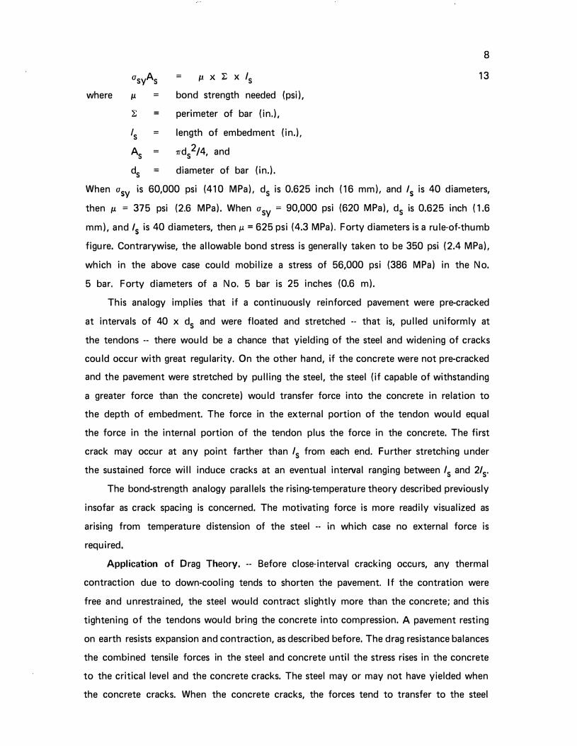
Bond-Strength Analogy. -- The force in a steel bar at the yield point is asyAs. To
develop sufficient anchorage in concrete to utilize the full force of the bar without pulling
out, the bar would have to be embedded a length equal to about 40 diameters. To derive
the bond strength needed, let
8
asyAs = 1J. X 1: X Is 13
where IJ. = bond strength needed (psi),
:E = perimeter of bar (in.),
's = length of embedment (in.).
As rrds 2/4, and
ds = diameter of bar (in.).
When a5y is 60,000 psi (410 MPa). ds is 0.625 inch (16 mm). and /5 is 40 diameters,
then p. = 375 psi (2.6 MPa). When asy = 90,000 psi (620 MPa), ds is 0.625 inch (1.6
mm), and /5 is 40 diameters, then p. = 625 psi (4.3 MPa). Forty diameters is a rule-of-thumb
figure. Contrarywise, the allowable bond stress is generally taken to be 350 psi (2.4 MPa).
which in the above case could mobilize a stress of 56,000 psi (386 MPa) in the No.
5 bar. Forty diameters of a No. 5 bar is 25 inches (0.6 m).
This analogy implies that if a continuously reinforced pavement were pre-cracked
at intervals of 40 x ds and were floated and stretched -- that is, pulled uniformly at
the tendons -- there would be a chance that yielding of the steel and widening of cracks
could occur with great regularity, On the other hand, if the concrete were not pre-cracked
and the pavement were stretched by pulling the steel, the steel (if capable of withstanding
a greater force than the concrete) would transfer force into the concrete in relation to
the depth of embedment. The force in the external portion of the tendon would equal
the force in the internal portion of the tendon plus the force in the concrete. The first
crack may occur at any point farther than Is from each end. Further stretching under
the sustained force will induce cracks at an eventual interval ranging between Is and 2/s.
The bond-strength analogy parallels the rising-temperature theory described previously
insofar as crack spacing is concerned. The motivating force is more readily visualized as
arising from temperature distension of the steel -- in which case no external force is
required.
Application of Drag Theory. -- Before close-interval cracking occurs, any thermal
contraction due to down-cooling tends to shorten the pavement. If the contration were
free and unrestrained, the steel would contract slightly more than the concrete; and this
tightening of the tendons would bring the concrete into compression. A pavement resting
on earth resists expansion and contraction, as described before. The drag resistance balances
the combined tensile forces in the steel and concrete until the stress rises in the concrete
to the critical level and the concrete cracks. The steel may or may not have yielded when
the concrete cracks. When the concrete cracks, the forces tend to transfer to the steel

9
and to induce yielding in the steel then and when further contraction ensues.
The length of pavement which generates a drag force equal to the yield strength
of the steel is
L (in a sy x percent steel
feet) = 100
14
When asy = 60,000 psi (414 MPa) and percent steel = 0.677, then L = 406.2 feet ( 104
m); when asy = 90,000 psi (620 MPa). L = 609.3 feet (186 m).
If the concrete is already cracked at close intervals, as explained by rising-temperature
situations, the steel alone determines the distance from an end where the drag forces
cause yielding of the steel and widening of the cracks. For mild steel, this would be
about 400 feet (120 m); for high-strength steel, this would be about 600 feet (185 m).
This introduces an apparent mismatch of logic inasmuch as the observed distance to the
first apparent crack has been in the order of 30 to 100 feet (9 to 30 m). Beyond the
first crack, the apparent interval shortens progressively until the normal, short, regular
interval becomes established. However, the first down-cooling or curing shrinkage may
occur before bond develops between the steel and concrete. For instance, concrete having
a tensile strength of 30 to 50 psi (0.2 to 0.35 MPa) would crack at 30- to 50-foot (9-
to 15-m) intervals and crack later at 2.5- to 6.0-foot (0.8- to 1.8-m) intervals. Only the
earliest shrinkage cracks would be at all apparent to the observer -- and they might be
more so farther inward from the end.
The two mechanisms superimpose near the end of a slab. The close-interval cracking
has been demonstrated experimentally to be independent of position in a pavement and
to be dependent upon the characteristics of the steel and concrete.
Whereas the very first cracking may occur at intervals of 30 to 50 feet (9 to 15
m) and whereas close-spaced cracking must await the development of nearly full strength
of the concrete and a critical rise in temperature, close-spaced cracks will not be readily
apparent near the end of the slab. However, if the tendons at the end of a slab were
pulled, the interval between cracks would be close-spaced; but the crack width would
be greatest nearest the end and would diminish farther inward into the slab and as drag
resistance rises in proportion to distance,
CRCP in Kentucky, -- Approximately 7.12 miles (11.5 km) [29 lane-miles (46
lane-km)] of continuously reinforced concrete pavement were placed using slip forms on
I 71 in Henry, Trimble, and Carroll Counties. Paving was completed there in late 1968
(3). The slab was 8 inches (203 mm) thick and contained 0.677 percent longitudinal steel
10
placed at a nominal depth of 3 ± 0.5 inches (76 ± 13 mm) below the surface. No. 5
deformed bars were spaced transversely at 5.5 inches (140 mm). Two inner lanes of mainline
pavement extending 4.7 miles (7.6 km) westbound on I 275 from I 75 in Boone and
Kenton Counties were built in 1971; the outer lane and a ramp from I 75 southbound
onto I 275 westbound were completed in 1972. No. 5 bars were used at intervals of
4. 75 inches (121 mm) in the 9-inch (229-mm) slabs. This provided 0.677 percent
longitudinal steel for both slab thicknesses. The minimum expected 28-day compressive
strength for pavement concrete was 3,500 psi (24 MPa), and the minimum expected 28-day
modulus of rupture was 550 psi (3.8 MPa) when tested in accordance with ASTM C 39
and ASTM C 78.
Crack surveys were made periodically on I 71 and I 275; 200 feet (61 m) in each
1,000 feet (305 m) were sampled on I 71; 100 feet (30 m) in each 1,000 feet (305
m) were sampled on I 275. Any crack, regardless of size, was counted and recorded.
The survey made in July 1969 on I 71 gave an average interval of 5.78 feet (1.76 m)
between cracks. In July 1970, another survey was conducted, and the average interval
between cracks was 4.14 feet (1.26 m). There was a strong tendency for cracks to occur
at intervals at or between 2.5 and 5 feet (0.8 and 1.5 m).
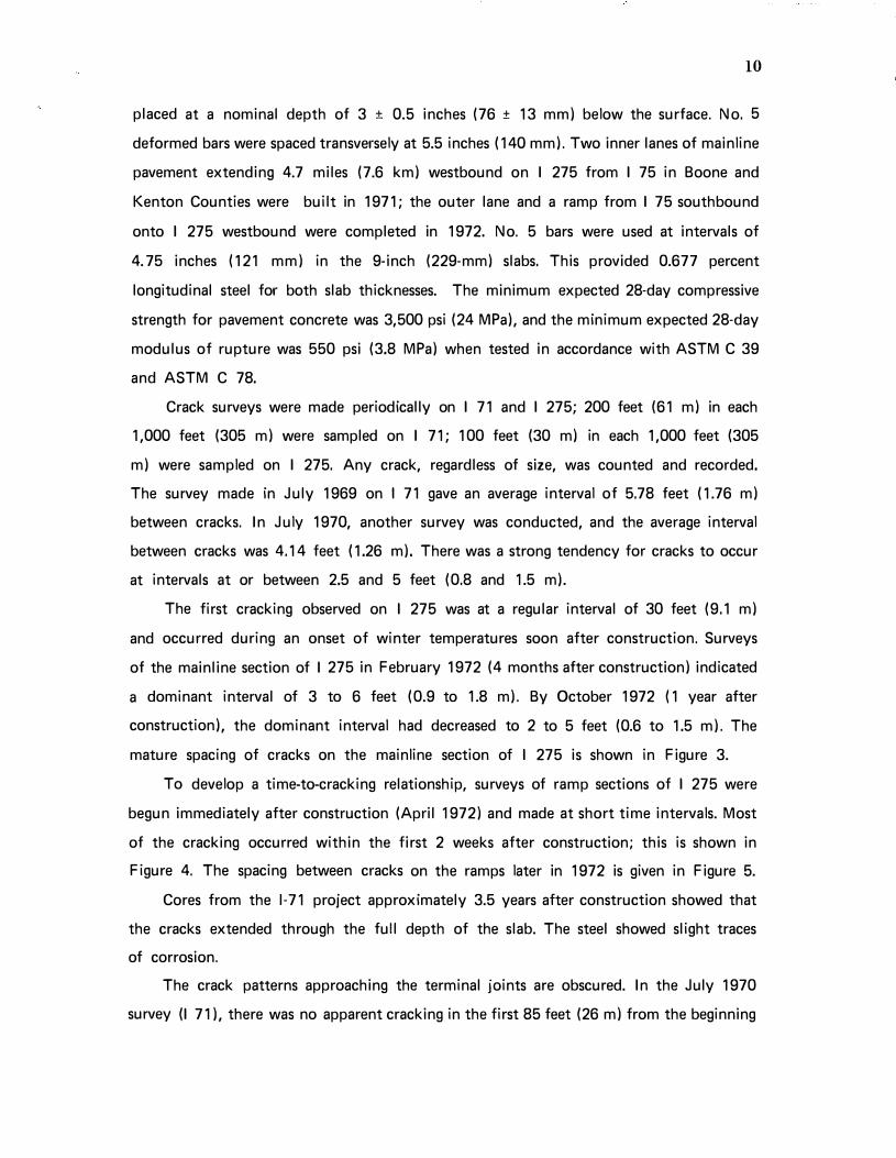
The first cracking observed on I 275 was at a regular interval of 30 feet (9.1 m)
and occurred during an onset of winter temperatures soon after construction. Surveys
of the mainline section of I 275 in February 1972 (4 months after construction) indicated
a dominant interval of 3 to 6 feet (0.9 to 1.8 m). By October 1972 (1 year after
construction), the dominant interval had decreased to 2 to 5 feet (0.6 to 1.5 m). The
mature spacing of cracks on the mainline section of I 275 is shown in Figure 3.
To develop a time-to-cracking relationship, surveys of ramp sections of I 275 were
begun immediately after construction (April 1972) and made at short time intervals. Most
of the cracking occurred within the first 2 weeks after construction; this is shown in
Figure 4. The spacing between cracks on the ramps later in 1972 is given in Figure 5.
Cores from the 1-71 project approximately 3.5 years after construction showed that
the cracks extended through the full depth of the slab. The steel showed slight traces
of corrosion.
The crack patterns approaching the terminal joints are obscured. In the July 1970
survey (I 71), there was no apparent cracking in the first 85 feet (26 m) from the beginning

ll
station and no obvious cracking in the last 25 feet (8 m) approaching the ending station.
Several other end situations existed within this project, and all conformed more or less
to this pattern. Ends, of course, are free to expand and contract to some extent.
Apparently, traffic had little influence on the crack interval on I 275. The incidence
of cracking in the outside lane was slightly greater than in the two inside lanes on the
mainline.
The construction season and the early curing temperatures may have affected early
crack development but had little or no affect on the ultimate crack intervals. I 71 and
the mainline inner lanes of I 275 were paved in the fall; the outer lane and a ramp on
I 275 were paved in early spring. The mainline inner lanes of I 275 which were exposed
to cold temperatures at an early curing age first developed cracks at a regular interval
of about 30 feet (9 m); otherwise, the majority of cracking occurred at an early age;
and all pavements seemed to reach an equilibrium in cracking after approximately 1 year.
BUCKLING
Thermal compression in a pavement occurs when the temperature rises and when
free expansion is not permitted because of natural or imposed constraints. Constraints
may be partial or complete. The actual distension or elongation together with any further
elongation which would occur upon removal of any constraints is equal to the free
expansion. That portion of the expansion which would occur if constraints were removed
is virtual expansion, and that portion of the strain is virtual strain. The product of this
strain and the modulus of elasticity is stress.
A plain concrete pavement undergoing a 100" F (56" C) rise would have a free
expansion of about 3 feet (5.5 x 10-6 x 1 00" F x 5,280) per mile (0.57 m per km).
If completely constrained, the stress rise would be about 2, 750 psi (19 MPa) -- that is,
5.5 x 10-6 x 100° F x 5 x 10⁶. Indeed, this stress rise alone is likely to exceed 50 percent
of the compressive strength of the concrete and is, therefore, fatiguing to the concrete.
Extreme effects at points of weakness and (or) reduced sections have been described
previously. An overthrust of 3 feet (0.9 m) or an upthrust or arching of slabs could occur.
This is a form of buckling,
A continuous strand of reinforcing steel undergoing a 1 00" F (56" C) rise would have
a free expansion of 3.4 feet (6.5 x 10-6 x 1 00" F x 5,280) per mile (0.6 m per km)
-- that is, approximately 0.4 feet per mile (76 mm per km) greater than the expansion

12
of concrete. S-shaped bends or laps of several inches (mm) have been noted in instances
where continuously reinforced pavements have blown up or shattered.
Partial-width patches, especially those made with bituminous concrete, tend to invite
buckling and blowups to occur later. Perhaps it would be more appropriate to state that
any reduction in cross section or bearing area of the cross section, such as may be caused
by deterioration and removal of concrete and the concentration of compressive forces
onto the remaining area may lead to blowups or buckling. Partial-width patching, therefore,
should include a compression relief joint extending the full width of the pavement.
SIMULATIONS
I nasmuch as the theory attributing close-spaced cracking in continuously reinforced
concrete to the greater thermal expansion of the steel seemed to evoke disbelief when
first proffered (5), a demonstration was designed to induce cracking without applying
external force. First, a beam, 4 inches by 4 inches by 12 feet (100 mm by 100 mm
by 3.6 m) was cast about a No. 5 re-bar (Grade 40, a5y = 50,900 psi (351 MPa)) (Figure
6) and cured until strengths of 703 psi (0.485 MPa) and 4,931 psi (3.4 MPa.) were reached
in tension and in compression. The beam was enveloped and warmed by heated air. To
monitor temperatures, thermocouples were installed in the concrete at various depths; and
to monitor cracking of concrete, yielding of steel, and mere slip, Dunegan acoustic emission
instrumentation was attached to the steel and concrete. The warming proceeded slowly
to about 180' F (82'C), and only weak emissions were detected. Later, the re-bar was
heated electrically by attaching arch-welding equipment to the exposed ends. It was found
that 250 to 300 amperes produced a rate of heating which would achieve 180' F (82'C)
in less than an hour. The heating produced intensive emissions at times from detectors
mounted on the steel and mild outbursts from the concrete. The cracks are lined in Figure
7, Beam 1.
A second beam was made using Grade 60 steel (a5y � 67,727 psi (466 MPa)). When
heated to about 180' F (82'C). the steel emitted very little "noise;" but the concrete
had emitted several mild outbursts (see Figure 7, Beam 2). I t appeared that the steel
had yielded in the first beam but not in the second. This also appeared to be so from
the standpoint of the strength of the concrete and asy of the steel.
To further demonstrate the yielding situation, a third beam 4 inches by 6 inches
by 12 feet (100 mm by 150 mm by 3.6 m) containing a 3/8-inch (9.5-mm) Grade 60

13
bar was made and tested as before. Strong outbursts of "noise" from the steel were again
related to yielding of the steel; and milder noises were related to cracking of the concrete.
The spacing of the cracks was as shown in Figure 7, Beam 3. Attenuations of noise rates
correspond to relief of stress in the steel by cracking of the concrete. In the test in which
the steel yielded, some 28,000 acoustic emission counts were recorded. The maximum
re-bar temperature was 160'F (71'C). In the test which precluded yielding, only about
9,000 acoustic emission counts were recorded, though the maximum test temperature of
�he steel was 210' F (99'C). Subsequent acoustic emission tests on concrete beams and
cylinders revealed that the quantity of acoustic emission from fracturing concrete depends
on the strength and mode of loading. The results indicate that concrete is probably not
a high emitter. Therefore, the major source of acoustic emissions in these tests was the
reinforcing steel.
IMPLICATIONS FROM THEORIES
Deteriorations as witnessed and explained by the mechanisms or theories advanced
here are not directly associated with live load, traffic, or use of the pavement. It is implied
that cracking would have occurred even if there had been no hauling or travelling on
the pavement. It is implied, moreover, that there are defects in design concepts ·· which,
if corrected, would surely extend the life and efficiency of concrete pavements generally
and would yield service to the user on a better investment-recovery basis.
Beam action is severely reduced by close-spaced cracking. The short slabs tend to
rotate when the load is over a crack; the steel undoubtedly provides some hinge action
unless it becomes fatigued and is broken. Bearing pressures beneath the pavement are
greater when the wheel loads are centered over the cracks.
Continuously reinforced pavements undergo numerous push-pull cycles; the steel
yields; and the concrete fatigues. Buckling and blowups occur because expansion joints
are not provided at intervals of one-half to three-quarters of a mile (0.8 to 1.2 km).
To prevent close-spaced cracking, the steel would have to be smooth, lubricated bars.
The bars might be threaded at the ends and be snugged by nuts when the curing
temperature is highest. Snugging again after significant strength gain and at summer-high
temperatures would bring the tendons into tension upon cooling and tend to reduce
contraction cracking to some degree. The slab length, from this point of view, probably
should not exceed BOO to 1,000 feet (240 to 300 m).

14
APPENDIX I. -- REFERENCES
1. J. Antrim and J. F. McLaughlin, A Study of the Fatigue Properties of Air-Entrained
Concrete, Report No. 26, Joint Highway Research Project, Purdue University; October
1958.
2. V. E. Bukovatz, C. F. Crumpton, and H. E. Worley, Study of D-Cracking in Portland
Cement Concrete Pavements, State Highway Commission of Kansas, 1973; also Kansas
Concrete Pavement as Related to D-Cracking, Record 525, Transportation Research
Board, 1974.
3. R. C. Deen, Continuously Reinforced Concrete Pavement, Bulletin 99, College of
Engineering, University of Kentucky, June 1972.
4. H. W. Griffin, Transverse Joints in the Design of Heavy Duty Concrete Pavements,
Proceedings, Highway Research Board, 1943.
5. J. H. Havens, Memo Report, Kentucky Department of Highways, December B, 1970.
6. J. H. Havens, The D-Cracking Phenomenon: A Case Study for Pavement
Rehabilitation, Kentucky Bureau of Highways, Division of Research, April 1976.
7. Interim Report on D-Cracking of Concrete Pavements in Ohio, Portland Cement
Association, March 1972.
B. W. R. Woolley, Suggested Design for a Continuously Reinforced Concrete Pavement
with No Joints, Public Roads Administration, 1945.
APPENDIX II. -- NOTATION
area of steel
Cc = coefficient of thermal expansion of concrete
C5 = coefficient of thermal expansion of steel
D = thickness of concrete slab (height of slab element)
diameter of steel bar
Ec modulus of elasticity of concrete
E5 modulus of elasticity of steel
F = longitudinal drag force
f coefficient of friction between the pavement and the subgrade
L = length of concrete slab element
change in length of slab due to stress rise in the concrete

L5 = change in length of slab due to stress rise in the steel
/5 = length of embedment of steel bar in concrete
N = number of load applications
s
w
w
L\L
LIT
a
=
=
=
stress level
normal force (or weight of pavement)
width of concrete slab element
change in length or length of slab under consideration
change in temperature
stress rise in concrete per unit length
stress rise in steel per unit length
density (unit weight) of concrete
total stress rise
critical stress
yield stress of steel
bond strength (between concrete and steel)
perimeter of steel bar
15

CRACKING IN CONCRETE PAVEMENTS
KEYWORDS: Bond strength; Concrete pavements; Continuously rein
forced concrete pavements; Cracking; D-cracking; Fatigue; Plain and
jointed pavements; Temperature expansions and contractions
ABSTRACT: Several theories explaining the mechanisms and intervals of
cracking of portland cement concrete pavements are reviewed. Crack and
blowup intervals for plain and jointed pavements and continuously rein
forced concrete pavements were predicted and verified by field observa
tions.
REFERENCE: Deen, Robert C.; Havens, James H.; Rahal, Assaf S.; and
Azevedo, W. Vernon; Cracking in Concrete Pavements
16

17
CRACKING IN CONCRETE PAVEMENTS
KEYWORDS: Bond strength; Concrete pavements; Continuously reinforced concrete
pavements; Cracking; D-cracking; Fatigue; Plain and jointed pavements; Temperature
expansions and contractions
ABSTRACT: Several theories explaining the mechanisms and intervals of cracking of
portland cement concrete pavements are reviewed. For plain and jointed pavements, the
cracking interval was found to be approximately twice (when expressed in feet) the strength
(when expressed in psi) of the concrete. For new concrete with a 30-psi (0.2 MPa) tensile
strength after only a few hours, the drying-shrinkage or cooling crack interval is
approximately 60 feet (18 m). This is a basis for sawing joints at approximately 50-feet
(15-m) intervals before the concrete is 16 hours old. For concrete with a compressive
strength of 4,500 psi (31 MPa) and sawed joints, the interval between blowups or crushed
joints would be about 1 mile (1.6 km). This is the basis for spacing expansion joints
approximately 0.5 to 1 mile (0.8 to 1.6 km) apart. A theory of differential temperature
expansion-contraction between concrete and steel explains the ultimate crack interval of
continuously reinforced concrete pavements between 2 and 6 feet (0.6 and 2 m). This
interval was verified by field observations.
REFERENCE: Deen, Robert C.; Havens, James H.; Rahal, Assaf S.; and Azevedo, W.
Vernon; Cracking in Concrete Pavements

Figure 1.
18
Normal Shrinkage Cracks, Controlled by Sawed Joint.
Figure 2. Shrinkage Crack; Either the Joint was Sawed too Late or the Dowel Bars Locked or Froze (Misaligned).

19
20�-------------------------------------------.
� 15 (.) <t a::: (.)
l.i.. 10 0
1-ffi 5 (.) a::: Li.J a..
0
Figure 3.
2 3 4
CRACK
5 6 7 8
INTERVAL
9 10 >10
Mature Spacing of Cracks on Mainline Section of I 275.

20
70.-----------------------------------------�
60 t-
C/) 50 1-� u <( 5 40 t-1.1.. 0 1- 30 z w u a:: 20 -w 0..
10 ....
I 10
Figure 4.
I 20
�
I I I 50
I
60 I �
30 40
ELAPSED TIME (DAYS)
70 80
Spacing between Cracks in Relation to Time (Age of Concrete) on Ramp Section of I 275.
90

20
en � (.) <( 15 a:: (.)
LL 0
10
1-:z LLI (.) a:: LLI 5 a..
0
Figure 5.
2 3 4
CRACK
5 6 7
INTERVAL
Mature Spacing of Cracks on Ramp Section of I 275.
21

NO. 5 DEFORMED STEEL
Figure 6. Test Specimen; Beam Used to Simulate Cracking Conditions in Reinforced Concrete.
Figure 7. Test Beams Showing Cracks (Lined) I nduced by Warming Reinforcing Steel (by Resistance Heating).
22