Ijaers oct-2014-013-electronic toll collection system for billing using wireless communication
Kolekar et al, International Journal of Advanced Engineering Research and Studies E-ISSN2249–8974
Int. J. Adv. Engg. Res. Studies/IV/IV/July-September,2015/09-12
Research Paper
DESIGN, DEVELOPMENT AND STRUCTURAL ANALYSIS OF
UNIVERSAL JOINT 1Dhananjay S Kolekar, 2Abhay M. Kalje, 3Swapnil S Kulkarni
Address for Correspondence 1ME(Mech-Design), 2Associate Professor & Head of Dept, in N.B. Navale Sinhagad College of Engineering,
Solapur, Solapur University. 3Associate, Advent Tool Tech, Bhosari, Pune India
ABSTRACT The steering system and steering column are the one of the most important devices of an automobile.it is a very crucial part to attain stability and steady movement of the vehicle. A universal joint consist of two yokes, one on each shaft, connected by cross-shaped intermediate member i.e. spider. Yoke assembly are always subjected to torsion and shear. Motion transmission system of vehicles consist several components which sometimes encounter unfortunate failures. Yoke assembly are rotating part and sometimes suffer from fatigue by application of variable torque.in this paper finite element analysis of the component is carried out to find the stress and displacement of the final product. For modelling of the component ProE software is used. Pre-processing work like meshing and analysis work is carried out in HYPERWORKS software. Using FEA analysis, we can identify the nature and characteristics of stresses acting on the yoke and evaluate the influence of the load/mass geometry/boundary conditions over the yoke. KEYWORDS: Universal joint, steering yoke, ProE, HYPERWORKS, FEA.
INTRODUCTION The purpose of a steering system is to control the direction of the vehicle by operating the steering wheel of the steering system. Movement of steering wheel by the driver should cause an accurate response of the road wheels. The intermediate shaft connects the steering shaft to the steering pinion. These components cannot be arranged on the same axis due to the vehicle design limitations. They are arranged with the universal joints. The stresses in either direction, while moving the vehicle to the right or to the left, happen to be a source of failure of the mechanical joint. The two halves of the yoke, the web connecting the two halves or the shaft in the linkages are prone to failure. In such event, the driver could lose control leading to an accident. A universal joint also known as universal coupling, U joint, Cardan joint, Hardy-Spicer joint, or Hooke’s joint is a joint or coupling used to connect rotating shafts that are coplanar, but not coinciding. A universal joint is a positive, mechanical connection used to transmit motion, power or both. Each universal joint assembly consists of three major components: two yokes (flange and weld) and a cross trunnion. An automotive flange yoke has a machined flat face which may be affixed through a bolted connection to the rear differential of a vehicle. A weld yoke incorporates a machined step, and is inserted into the end of the driveshaft and welded in place. The cross trunnion is used to deliver rotation from one yoke to another using four needle pin bearings.
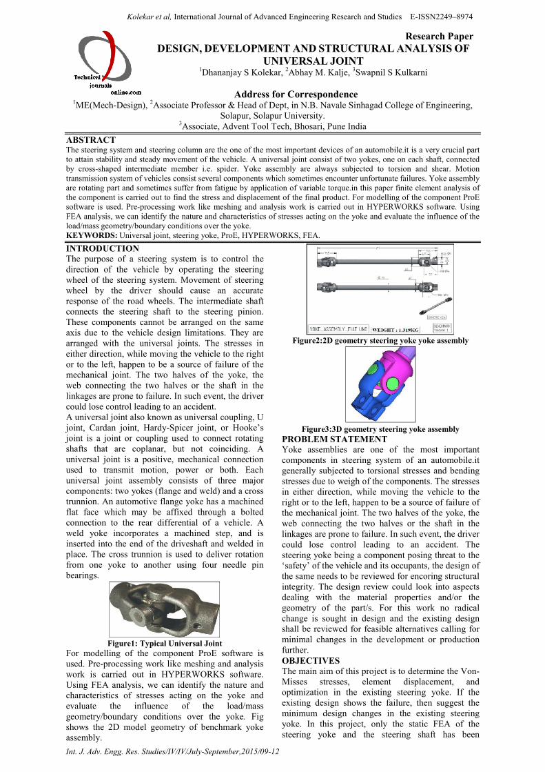
Figure1: Typical Universal Joint
For modelling of the component ProE software is used. Pre-processing work like meshing and analysis work is carried out in HYPERWORKS software. Using FEA analysis, we can identify the nature and characteristics of stresses acting on the yoke and evaluate the influence of the load/mass geometry/boundary conditions over the yoke. Fig shows the 2D model geometry of benchmark yoke assembly.
Figure2:2D geometry steering yoke yoke assembly
Figure3:3D geometry steering yoke assembly
PROBLEM STATEMENT Yoke assemblies are one of the most important components in steering system of an automobile.it generally subjected to torsional stresses and bending stresses due to weigh of the components. The stresses in either direction, while moving the vehicle to the right or to the left, happen to be a source of failure of the mechanical joint. The two halves of the yoke, the web connecting the two halves or the shaft in the linkages are prone to failure. In such event, the driver could lose control leading to an accident. The steering yoke being a component posing threat to the ‘safety’ of the vehicle and its occupants, the design of the same needs to be reviewed for encoring structural integrity. The design review could look into aspects dealing with the material properties and/or the geometry of the part/s. For this work no radical change is sought in design and the existing design shall be reviewed for feasible alternatives calling for minimal changes in the development or production further. OBJECTIVES The main aim of this project is to determine the Von-Misses stresses, element displacement, and optimization in the existing steering yoke. If the existing design shows the failure, then suggest the minimum design changes in the existing steering yoke. In this project, only the static FEA of the steering yoke and the steering shaft has been
Kolekar et al, International Journal of Advanced Engineering Research and Studies E-ISSN2249–8974
Int. J. Adv. Engg. Res. Studies/IV/IV/July-September,2015/09-12
performed by the use of software. Afterword’s Determine design alternatives and analyze for iterations. Then the combination of finite element technique with aspect of weight reduction is to be made and finally Comparison of analytical results of any one variant with Experimental results for validation. SPECIFICATIONS FOR A STEERING YOKE
Material – Generic steel Density - 7.9��� ton/mm3 Poisson’s ratio – 0.3 Modulus of elasticity – 2.10e5Mpa Young’s modulus – 205Gpa Yield strength – 250 Mpa
ANALYSIS OF STEERING YOKE BY USING
HYPERWORKS With the advancement with the finite element analysis (FEA) modeling. Model based design of mechanical structures is replacing the traditional trial and error approach. Here the finite element analysis of steering yoke is done in hyperworks software there are three steps 1.Pre-processing, 2. Processing, 3.Post-processing Pre-processing After modeling the component and importing to hypermesh window meshing is carried out the tetrahedral meshing approach is employed for the meshing of the solid region geometry. Tetrahedral meshing produces high quality meshing for boundary representation of solid structural model. Since the tetrahedral is found to be the best meshing technique Divide the whole model into several parts and mesh one by one in different mesh densities.
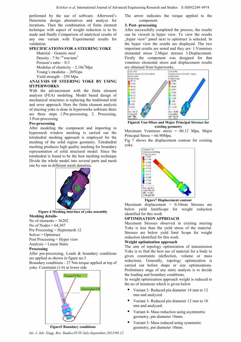
Figure 4 Meshing interface of yoke assembly
Meshing details- No of elements = 36202 No of Nodes = 64,307 Pre Processing = Hypremesh 12 Solver = Optistruct Post Processing = Hyper view Analysis = Linear Static Processing After pre-processing, Loads & boundary conditions are applied as shown in figure no.5 Boundary conditions - 27 Nm torque applied at top of yoke. Constraint (1-6) at lower side
Figure5 Boundary conditions
The arrow indicates the torque applied to the component.
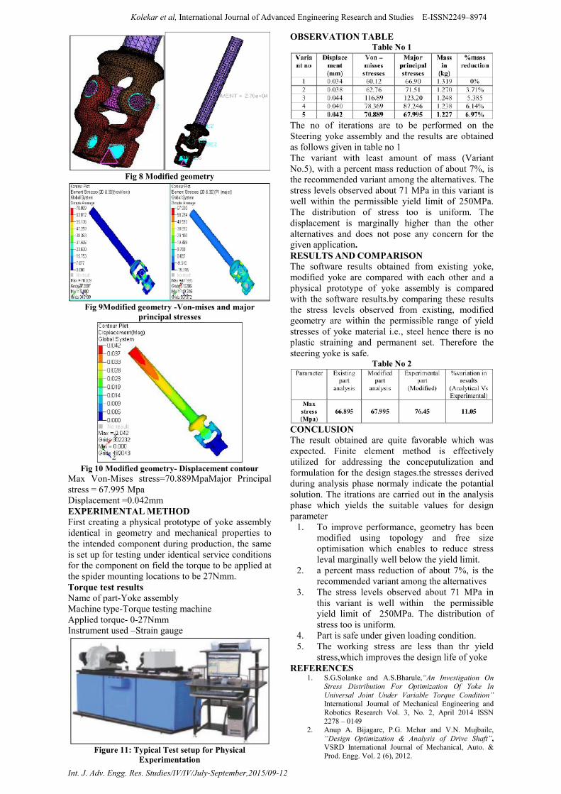
3. Post- processing After successfully completed the process, the results can be viewed in hyper view. To view the results „hyper view‟ panel next to optistruct is selected. In the hyper view the results are displayed. The two important results are noted and they are: 1.Vonmises elemental stress 2.Major stresses 3.Displacement. Firstly the component was designed for that vonmises elemental stress and displacement results are obtained from hyperworks.
Figure6 Von-Mises and Major Principal Stresses for
existing geometry Maximum Vonmises stress = 60.12 Mpa, Major Principal Stress = 66.90Mpa. Fig 7 shows the displacement contour for existing yoke.
Figure7 Displacement contour
Maximum displacement = 0.34mm Stresses are below yield limitScope for weight reduction identified for this work OPTIMISATION APPROACH Maximum Stresses observed in existing steering Yoke is less than the yield stress of the material. Stresses are below yield limit Scope for weight reduction identified for this work. Weight optimisation approach The aim of topology optimization of transmission Yoke is to find the best use of material for a body to given constraints (deflection, volume or mass reduction). Generally, topology optimization is carried out before shape or size optimizations. Preliminary stage of any static analysis is to decide the loading and boundary conditions. In weight optimization approach weight is reduced to the no of iterations which is given below
• Variant 2- Reduced pin diameter 14 mm to 12 mm and analyzed.
• Variant 3- Reduced pin diameter 12 mm to 10 mm and analyzed.
• Variant 4- Mass reduction using asymmetric geometry, pin diameter 10mm.
• Variant 5- Mass reduced using symmetric geometry, pin diameter 10mm.
Kolekar et al, International Journal of Advanced Engineering Research and Studies E-ISSN2249–8974
Int. J. Adv. Engg. Res. Studies/IV/IV/July-September,2015/09-12
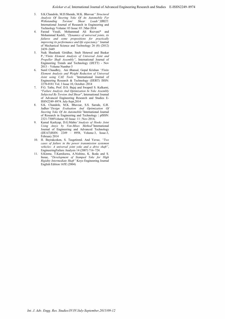
Fig 8 Modified geometry
Fig 9Modified geometry -Von-mises and major
principal stresses
Fig 10 Modified geometry- Displacement contour
Max Von-Mises stress=70.889MpaMajor Principal stress = 67.995 Mpa Displacement =0.042mm EXPERIMENTAL METHOD First creating a physical prototype of yoke assembly identical in geometry and mechanical properties to the intended component during production, the same is set up for testing under identical service conditions for the component on field the torque to be applied at the spider mounting locations to be 27Nmm. Torque test results Name of part-Yoke assembly Machine type-Torque testing machine Applied torque- 0-27Nmm Instrument used –Strain gauge
Figure 11: Typical Test setup for Physical
Experimentation
OBSERVATION TABLE Table No 1
The no of iterations are to be performed on the Steering yoke assembly and the results are obtained as follows given in table no 1 The variant with least amount of mass (Variant No.5), with a percent mass reduction of about 7%, is the recommended variant among the alternatives. The stress levels observed about 71 MPa in this variant is well within the permissible yield limit of 250MPa. The distribution of stress too is uniform. The displacement is marginally higher than the other alternatives and does not pose any concern for the given application. RESULTS AND COMPARISON The software results obtained from existing yoke, modified yoke are compared with each other and a physical prototype of yoke assembly is compared with the software results.by comparing these results the stress levels observed from existing, modified geometry are within the permissible range of yield stresses of yoke material i.e., steel hence there is no plastic straining and permanent set. Therefore the steering yoke is safe.
Table No 2
CONCLUSION The result obtained are quite favorable which was expected. Finite element method is effectively utilized for addressing the conceputulization and formulation for the design stages.the stresses derived during analysis phase normaly indicate the potantial solution. The itrations are carried out in the analysis phase which yields the suitable values for design parameter
1. To improve performance, geometry has been modified using topology and free size optimisation which enables to reduce stress leval marginally well below the yield limit.
2. a percent mass reduction of about 7%, is the recommended variant among the alternatives
3. The stress levels observed about 71 MPa in this variant is well within the permissible yield limit of 250MPa. The distribution of stress too is uniform.
4. Part is safe under given loading condition. 5. The working stress are less than thr yield
stress,which improves the design life of yoke REFERENCES
1. S.G.Solanke and A.S.Bharule,“An Investigation On Stress Distribution For Optimization Of Yoke In Universal Joint Under Variable Torque Condition” International Journal of Mechanical Engineering and Robotics Research Vol. 3, No. 2, April 2014 ISSN 2278 – 0149
2. Anup A. Bijagare, P.G. Mehar and V.N. Mujbaile, “Design Optimization & Analysis of Drive Shaft”, VSRD International Journal of Mechanical, Auto. & Prod. Engg. Vol. 2 (6), 2012.
Kolekar et al, International Journal of Advanced Engineering Research and Studies E-ISSN2249–8974
Int. J. Adv. Engg. Res. Studies/IV/IV/July-September,2015/09-12
3. S.K.Chandole, M.D.Shende, M.K. Bhavsar“ Structural Analysis Of Steering Yoke Of An Automobile For Withstanding Torsion/ Shear Loads”,IJRET: International Journal of Research in Engineering and Technology Volume: 03 Issue: 03 | Mar-2014
4. Farzad Vesali, Mohammad Ali Rezvani* and Mohammad Kashfi, “Dynamics of universal joints, its failures and some propositions for practically improving its performance and life expectancy” Journal of Mechanical Science and Technology 26 (8) (2012) 2439~2449
5. Naik Shashank Giridhar, Sneh Hetawal and Baskar P.,“Finite Element Analysis of Universal Joint and Propeller Shaft Assembly”, International Journal of Engineering Trends and Technology (IJETT) - Nov 2013 – Volume Number 5
6. Sunil Chaudhry, Ani tBansal, Gopal Krishan “Finite Element Analysis and Weight Reduction of Universal Joint using CAE Tools ”International Journal of Engineering Research & Technology (IJERT) ISSN: 2278-0181 Vol. 3 Issue 10, October- 2014
7. P.G. Tathe, Prof. D.S. Bajaj and Swapnil S. Kulkarni, “Failure Analysis And Optimization In Yoke Assembly Subjected By Torsion And Shear”, International Journal of Advanced Engineering Research and Studies E-ISSN2249–8974. July-Sept,2014
8. S.K. Chandole, M.K. Bhavsar, S.S. Sarode, G.R. Jadhav“Design Evaluation And Optimization Of Steering Yoke Of An Automobile”International Journal of Research in Engineering and Technology | pISSN: 2321-7308Volume: 03 Issue: 11 | Nov-2014,
9. Kamal Kashyap, D.G.Mahto“Analysis of Hooks Joint Using Ansys by Von-Mises Method”International Journal of Engineering and Advanced Technology (IJEAT)ISSN: 2249 – 8958, Volume-3, Issue-3, February 2014
10. H. Bayrakceken, S. TasgetirenI. And Yavuz, “Two cases of failure in the power transmission systemon vehicles: A universal joint yoke and a drive shaft”, EngineeringFailure Analysis 14 (2007) 716–724.
11. S.Kinme, T.Kamikawa, A.Nishino, K. Ikeda and S. Inoue, “Development of Stamped Yoke for High Rigidity Intermediate Shaft” Koyo Engineering Journal English Edition 165E (2004)