
Research on Bolt Connection Loose Mechanism under Dynamic ...
11
Research on Bolt Connection Loose Mechanism under Dynamic combination load Zifan Fang 1, 2, 3, a , Hang Wu 1, b , Kongde He 1, c , Xufu Ge 1 , Xuguang Xie 1 and Hao Xu 1 1 College of Mechanical & Power Engineering China Three Gorges Univ., Yichang 443002, Hubei China; 2 Hubei Key Laboratory of Hydroelectric Machinery Design and Maintenance, China Three Gorges Univ., Yichang 443002, Hubei China; 3 Hubei Provincial Collaborative Innovation Center for New Energy Microgrid, China Three Gorges Univ., Yichang 443002, Hubei China. a [email protected], b [email protected], c [email protected] Abstract. Focusing on the loosening of bolt connection in the rotating mechanism under dynamic tension compression and shear combination load, virtual prototyping technology and finite element analysis method are applied in studying the failure mechanism and its influencing factors. Firstly, based on the virtual prototype technology, the load of failure bolt connection structure is extracted; secondly, the finite element method is used to analyze the influence factors of bolt number, pre-tightening, connection thickness and spring shim. The evaluation index system of digital analysis is set up to guide the improved design for the anti-loosening measures. In this thesis, the improved design and research on the bolt of a servo device rotating mechanism is taken as an example. The method of digital design and analysis is carried out, which solves the problem of bolt connection loose. The conclusion shows that the improved design is consistent with the practical engineering, and bolt connection structure is free from loosening and failure. Keywords: Bolt connection; Dynamic combined load; Failure mechanism; Evaluation criterion of bolt loose. 1. Introduction It is well known that the bolt connection is broadly adopted in machines or equipment and its operation condition greatly influences the smooth operation of machine equipment. Especially when the bolt connection in the rotating mechanism is under the load of dynamic tension compression and shear combination, the bolt connection is more likely to loose, even to fall off. To solve this problem, many foreign researchers perform researches in which the finite element method is applied. For example, the American scholar Hess[1-5] points out that the if there is localized slide on the bolt, the bolt can be loose under relatively minor shearing action; the Japanese scholar Satoshi Izumi[6] believes the spring shim may accelerate the nut loosening; the Germany scholar G.Dinger[7] puts forward an idea that the localized slip on the contact area of screw head may also cause the bolt loosening; the American scholar Jiang Y [8-11] recommend that the main reason of bolt loosening is the stress redistribution and deformation of ratchet effect caused by local plastic deformation effected by the initial pre-tightening force. However, the domestic scholar Luo Chuanxi[12] proposes that the fundamental reason of bolt loosening is the alternatively positive and negative frequent variations of the bending torque and the torque, while the important reason of the bolt loosening lies in the actual installed pretightening force which can't meet the requirement; another domestic scholar Kong Xiangwei[13] suggests that when the bolt is under the limit load, there might be small displacement of the bolt which is in the bolt holes and under the long-term reciprocating load, the nut may become loose gradually; the scholar Yangming[14] 6-7 figures out that the accumulative sliding under the cyclic loading causes the bolt looseness. In this paper, the loosening of the bolt connection under International Conference on Artificial Intelligence and Engineering Applications (AIEA 2016) Copyright © 2016, the Authors. Published by Atlantis Press. This is an open access article under the CC BY-NC license (http://creativecommons.org/licenses/by-nc/4.0/). Advances in Computer Science Research, volume 63 506
Transcript of Research on Bolt Connection Loose Mechanism under Dynamic ...

Research on Bolt Connection Loose Mechanism under Dynamic
combination load
Zifan Fang1, 2, 3, a, Hang Wu1, b, Kongde He1, c, Xufu Ge1, Xuguang Xie1
and Hao Xu1
1College of Mechanical & Power Engineering China Three Gorges Univ., Yichang 443002, Hubei China;
2Hubei Key Laboratory of Hydroelectric Machinery Design and Maintenance, China Three Gorges Univ., Yichang 443002, Hubei China;
3Hubei Provincial Collaborative Innovation Center for New Energy Microgrid, China Three Gorges Univ., Yichang 443002, Hubei China.
[email protected], [email protected], [email protected]
Abstract. Focusing on the loosening of bolt connection in the rotating mechanism under dynamic
tension compression and shear combination load, virtual prototyping technology and finite element
analysis method are applied in studying the failure mechanism and its influencing factors. Firstly,
based on the virtual prototype technology, the load of failure bolt connection structure is extracted;
secondly, the finite element method is used to analyze the influence factors of bolt number,
pre-tightening, connection thickness and spring shim. The evaluation index system of digital analysis
is set up to guide the improved design for the anti-loosening measures. In this thesis, the improved
design and research on the bolt of a servo device rotating mechanism is taken as an example. The
method of digital design and analysis is carried out, which solves the problem of bolt connection loose.
The conclusion shows that the improved design is consistent with the practical engineering, and bolt
connection structure is free from loosening and failure.
Keywords: Bolt connection; Dynamic combined load; Failure mechanism; Evaluation criterion of bolt loose.
1. Introduction
It is well known that the bolt connection is broadly adopted in machines or equipment and its
operation condition greatly influences the smooth operation of machine equipment. Especially when
the bolt connection in the rotating mechanism is under the load of dynamic tension compression and
shear combination, the bolt connection is more likely to loose, even to fall off. To solve this problem,
many foreign researchers perform researches in which the finite element method is applied. For
example, the American scholar Hess[1-5] points out that the if there is localized slide on the bolt, the
bolt can be loose under relatively minor shearing action; the Japanese scholar Satoshi Izumi[6]
believes the spring shim may accelerate the nut loosening; the Germany scholar G.Dinger[7] puts
forward an idea that the localized slip on the contact area of screw head may also cause the bolt
loosening; the American scholar Jiang Y [8-11] recommend that the main reason of bolt loosening is
the stress redistribution and deformation of ratchet effect caused by local plastic deformation effected
by the initial pre-tightening force. However, the domestic scholar Luo Chuanxi[12] proposes that the
fundamental reason of bolt loosening is the alternatively positive and negative frequent variations of
the bending torque and the torque, while the important reason of the bolt loosening lies in the actual
installed pretightening force which can't meet the requirement; another domestic scholar Kong
Xiangwei[13] suggests that when the bolt is under the limit load, there might be small displacement of
the bolt which is in the bolt holes and under the long-term reciprocating load, the nut may become
loose gradually; the scholar Yangming[14]6-7 figures out that the accumulative sliding under the
cyclic loading causes the bolt looseness. In this paper, the loosening of the bolt connection under
International Conference on Artificial Intelligence and Engineering Applications (AIEA 2016)
Copyright © 2016, the Authors. Published by Atlantis Press. This is an open access article under the CC BY-NC license (http://creativecommons.org/licenses/by-nc/4.0/).
Advances in Computer Science Research, volume 63
506
dynamic tension compression and shear load is studied by applying the virtual prototype technology
and the finite element analysis method.
2. Bolt Connection and the Loosening of It
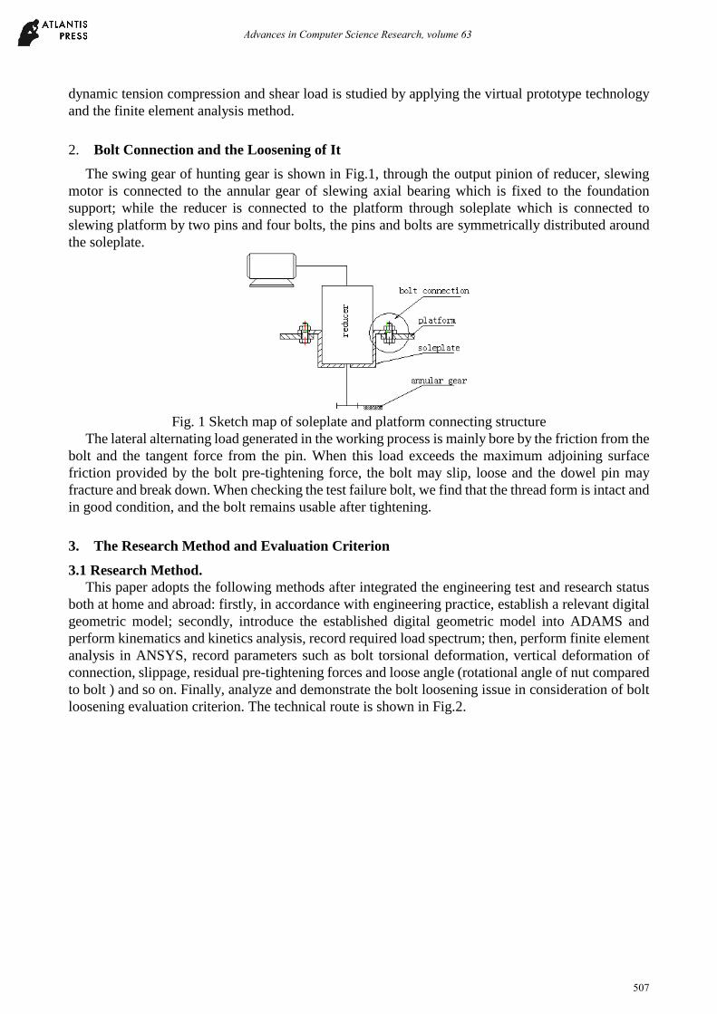
The swing gear of hunting gear is shown in Fig.1, through the output pinion of reducer, slewing
motor is connected to the annular gear of slewing axial bearing which is fixed to the foundation
support; while the reducer is connected to the platform through soleplate which is connected to
slewing platform by two pins and four bolts, the pins and bolts are symmetrically distributed around
the soleplate.
Fig. 1 Sketch map of soleplate and platform connecting structure
The lateral alternating load generated in the working process is mainly bore by the friction from the
bolt and the tangent force from the pin. When this load exceeds the maximum adjoining surface
friction provided by the bolt pre-tightening force, the bolt may slip, loose and the dowel pin may
fracture and break down. When checking the test failure bolt, we find that the thread form is intact and
in good condition, and the bolt remains usable after tightening.
3. The Research Method and Evaluation Criterion
3.1 Research Method.
This paper adopts the following methods after integrated the engineering test and research status
both at home and abroad: firstly, in accordance with engineering practice, establish a relevant digital
geometric model; secondly, introduce the established digital geometric model into ADAMS and
perform kinematics and kinetics analysis, record required load spectrum; then, perform finite element
analysis in ANSYS, record parameters such as bolt torsional deformation, vertical deformation of
connection, slippage, residual pre-tightening forces and loose angle (rotational angle of nut compared
to bolt ) and so on. Finally, analyze and demonstrate the bolt loosening issue in consideration of bolt
loosening evaluation criterion. The technical route is shown in Fig.2.
Advances in Computer Science Research, volume 63
507
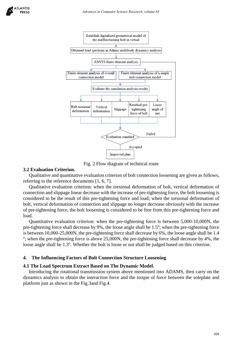
Fig. 2 Flow diagram of technical route
3.2 Evaluation Criterion.
Qualitative and quantitative evaluation criterion of bolt connection loosening are given as follows,
referring to the reference documents [1, 6, 7].
Qualitative evaluation criterion: when the torsional deformation of bolt, vertical deformation of
connection and slippage linear decrease with the increase of pre-tightening force, the bolt loosening is
considered to be the result of this pre-tightening force and load; when the torsional deformation of
bolt, vertical deformation of connection and slippage no longer decrease obviously with the increase
of pre-tightening force, the bolt loosening is considered to be free from this pre-tightening force and
load.
Quantitative evaluation criterion: when the pre-tightening force is between 5,000-10,000N, the
pre-tightening force shall decrease by 9%, the loose angle shall be 1.5o; when the pre-tightening force
is between 10,000-25,000N, the pre-tightening force shall decrease by 6%, the loose angle shall be 1.4
o; when the pre-tightening force is above 25,000N, the pre-tightening force shall decrease by 4%, the
loose angle shall be 1.3o. Whether the bolt is loose or not shall be judged based on this criterion.
4. The Influencing Factors of Bolt Connection Structure Loosening
4.1 The Load Spectrum Extract Based on The Dynamic Model.
Introducing the rotational transmission system above mentioned into ADAMS, then carry on the
dynamics analysis to obtain the interaction force and the torque of force between the soleplate and
platform just as shown in the Fig.3and Fig.4.
Advances in Computer Science Research, volume 63
508

Fig. 3 Curve of soleplate’s acting force to platform and the curve of component force along X,Y and Z
axis
Fig. 4 Curve of soleplate’s resultant torque to platform and curve of component torque around X,Y,Z
axis.
According to soleplate force-bearing curve, select the torque (1.3972s) when the platform carries
maximum force as the worst force-bearing torque, obtain the torque and its component of the force
that applying on the soleplate, conclude them in Tab.1.
Table 1 Acting force on platform, torque and its component
resultant force F/N Fx/N Fy/N Fz/N force 25 808 -16 902 19 453 1 396
resultant torque /N-mm X axis /N-m
Y axis /N-mm
Z axis /N-mm
torque 6 049 600 4 554 661 3 764 958 -129 5188
4.2 The Impact of The Number of Bolts and Pre-Tightening Force on The Bolt Looseness.
Establish relevant 3D model which is mainly consist of soleplate, platform, bolt and nut in Pro/E,
then introduce it into ANSYS/WORKBENCH. Set the mesh size of the model as: 5mm for soleplate
and platform, 3mm for bolt and nut. The material of model is constructional steel. It also adopts
accepted Young modulus which is 2.0X10⁵MPa, Poisson's ratio which is 0.3, and density which is
7.85X10⁻⁶kg/mm3. The finite element module is shown as Fig.5.
Fig. 5 Finite element model of overall connection
Advances in Computer Science Research, volume 63
509
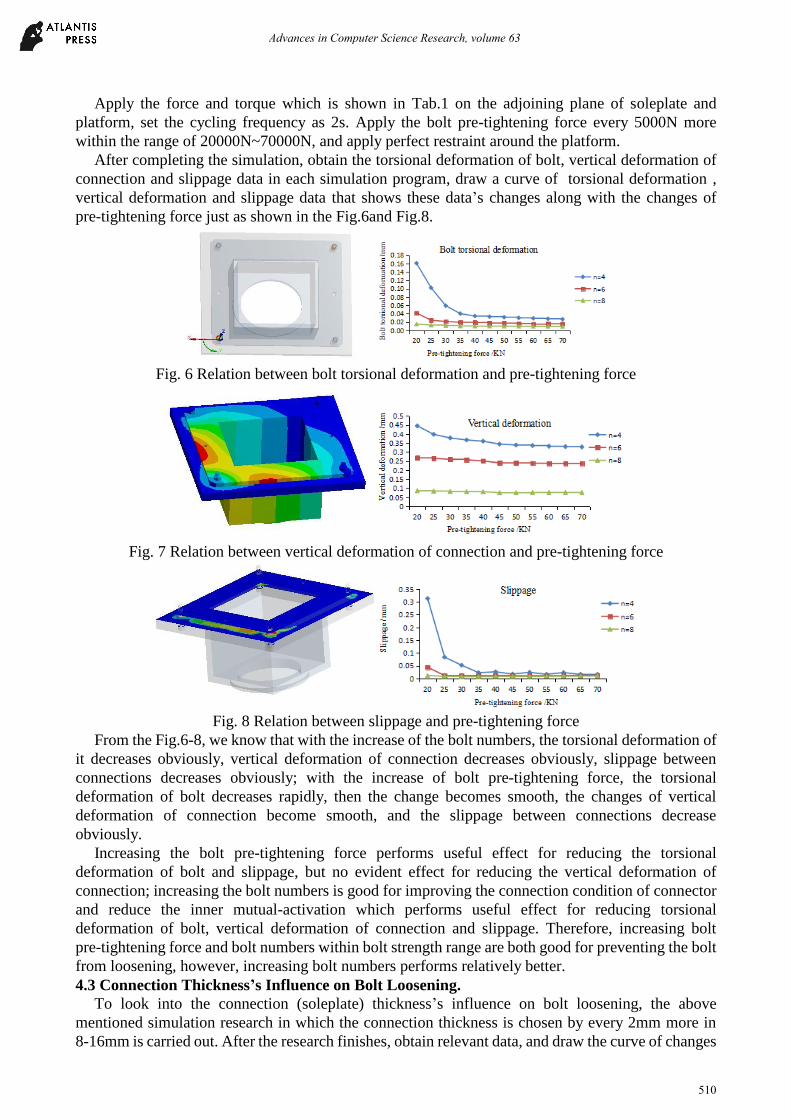
Apply the force and torque which is shown in Tab.1 on the adjoining plane of soleplate and
platform, set the cycling frequency as 2s. Apply the bolt pre-tightening force every 5000N more
within the range of 20000N~70000N, and apply perfect restraint around the platform.
After completing the simulation, obtain the torsional deformation of bolt, vertical deformation of
connection and slippage data in each simulation program, draw a curve of torsional deformation ,
vertical deformation and slippage data that shows these data’s changes along with the changes of
pre-tightening force just as shown in the Fig.6and Fig.8.
Fig. 6 Relation between bolt torsional deformation and pre-tightening force
Fig. 7 Relation between vertical deformation of connection and pre-tightening force
Fig. 8 Relation between slippage and pre-tightening force
From the Fig.6-8, we know that with the increase of the bolt numbers, the torsional deformation of
it decreases obviously, vertical deformation of connection decreases obviously, slippage between
connections decreases obviously; with the increase of bolt pre-tightening force, the torsional
deformation of bolt decreases rapidly, then the change becomes smooth, the changes of vertical
deformation of connection become smooth, and the slippage between connections decrease
obviously.
Increasing the bolt pre-tightening force performs useful effect for reducing the torsional
deformation of bolt and slippage, but no evident effect for reducing the vertical deformation of
connection; increasing the bolt numbers is good for improving the connection condition of connector
and reduce the inner mutual-activation which performs useful effect for reducing torsional
deformation of bolt, vertical deformation of connection and slippage. Therefore, increasing bolt
pre-tightening force and bolt numbers within bolt strength range are both good for preventing the bolt
from loosening, however, increasing bolt numbers performs relatively better.
4.3 Connection Thickness’s Influence on Bolt Loosening.
To look into the connection (soleplate) thickness’s influence on bolt loosening, the above
mentioned simulation research in which the connection thickness is chosen by every 2mm more in
8-16mm is carried out. After the research finishes, obtain relevant data, and draw the curve of changes
Advances in Computer Science Research, volume 63
510

of torsional deformation of bolt, vertical deformation of connection and slippage as is shown in Fig.
9-11.
Fig. 9 Relation between bolt torsional deformation and thickness
Fig. 10 Relation between vertical deformation of connection and thickness
Fig. 11 Relation between slippage and thickness
From the Fig.9-11, we know that: when the connection thickness is increased, the torsional
deformation of bolt, vertical deformation of connection and slippage reduce gradually. Therefore,
increasing connection thickness within permissible range is good for preventing the bolt from
loosening.
4.4 Spring Shim’s Influence on Bolt Loosening.
To look into the spring shim’s influence on bolt loosening, a 3D model of bolt, nut, simplified
platform, simplified soleplate and spring shim is established, as is shown in Fig.12.
Fig.12 3D Model with Spring Shim and Bolt Connection
Advances in Computer Science Research, volume 63
511
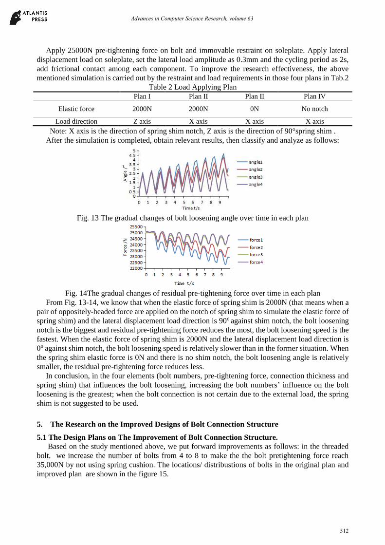
Apply 25000N pre-tightening force on bolt and immovable restraint on soleplate. Apply lateral
displacement load on soleplate, set the lateral load amplitude as 0.3mm and the cycling period as 2s,
add frictional contact among each component. To improve the research effectiveness, the above
mentioned simulation is carried out by the restraint and load requirements in those four plans in Tab.2
Table 2 Load Applying Plan
Plan I Plan II Plan II Plan IV
Elastic force 2000N 2000N 0N No notch
Load direction Z axis X axis X axis X axis
Note: X axis is the direction of spring shim notch, Z axis is the direction of 90°spring shim .
After the simulation is completed, obtain relevant results, then classify and analyze as follows:
Fig. 13 The gradual changes of bolt loosening angle over time in each plan
Fig. 14The gradual changes of residual pre-tightening force over time in each plan
From Fig. 13-14, we know that when the elastic force of spring shim is 2000N (that means when a
pair of oppositely-headed force are applied on the notch of spring shim to simulate the elastic force of
spring shim) and the lateral displacement load direction is 90o against shim notch, the bolt loosening
notch is the biggest and residual pre-tightening force reduces the most, the bolt loosening speed is the
fastest. When the elastic force of spring shim is 2000N and the lateral displacement load direction is
0o against shim notch, the bolt loosening speed is relatively slower than in the former situation. When
the spring shim elastic force is 0N and there is no shim notch, the bolt loosening angle is relatively
smaller, the residual pre-tightening force reduces less.
In conclusion, in the four elements (bolt numbers, pre-tightening force, connection thickness and
spring shim) that influences the bolt loosening, increasing the bolt numbers’ influence on the bolt
loosening is the greatest; when the bolt connection is not certain due to the external load, the spring
shim is not suggested to be used.
5. The Research on the Improved Designs of Bolt Connection Structure
5.1 The Design Plans on The Improvement of Bolt Connection Structure.
Based on the study mentioned above, we put forward improvements as follows: in the threaded
bolt, we increase the number of bolts from 4 to 8 to make the the bolt pretightening force reach
35,000N by not using spring cushion. The locations/ distribustions of bolts in the original plan and
improved plan are shown in the figure 15.
Advances in Computer Science Research, volume 63
512

Fig. 15 the distributions of bolts in the original plan and improved plan
5.2 The Comparison between The Original plan and Improved Plan.
In order to verify the correctness of the improved plan, we extract a single bolt model respectively
from the original plan and improved plan to analyze in a transient dynamic way. A single bolt model is
shown in Figure 16 in which includes a bolt, a nut, a simplified installation base and a simplified
platform.
Fig. 16 Three-dimension graph of a single bolt connection
Table 3 the plan of the load application
The primary plan The improved plan The type of nuts M12 M12
pre-tightening force /N
20000
35000 Slippage /mm 0.3 0.007
Just as the Tab. 3 shows, we apply loads and restraints to analyze original plan and improved plan
respectively. And after the analyses, we can obtain data and check the results.
Fig. 17 The situation of local contact on the bolt in the original plan
Fig. 18 The situation of local contact on the bolt in the improved plan
Advances in Computer Science Research, volume 63
513

In the comparison of partial contact of bolt in the original plan and improved plan, we can know
that: as is shown in Fig. 17, in the original plan, slip often occurs on the contact surface, which is
indicated as the orange part in Fig. 17. But as is shown in Fig. 18, in the improved one, slip does not
occur for the most of time, and the red part in Fig.18 indicates the cohesion part.
Fig. 19 The gradual changes of bolt loosening angles over time in original plan
Fig. 20 The gradual changes of bolt loosening angles over time in improved plan
Compare the differences of the changes of bolt loosening angles in original plan and the improved
plan, it is known that: in the original plan, the bolt loosening angle increase accumulatively with the
adding of simulation cycling period, and among the 10 simulation cycling periods, the biggest angle is
3.7°. While in the improved plan, the bolt loosening angle fluctuates back and forth with the adding of
simulation cycling period, but not increase accumulatively, and among the 10 simulation cycling
periods, the biggest angle is 0.07°.
Fig. 21 The gradual changes of residual pre-tightening force over time in original plan
Fig. 22 The changes of residual pre-tightening force with time in over time the improved plan
In the comparison with the changes of residual pre-tightening force in the two plans, we can learn
that during the 10 cycling periods, the residual pre-tightening force reduced to about 18,700N( a
decrease of 6.5%) in the original plan; but in the improved one, with extension of simulation cycling
periods, the wave of residual pre-tightening force just fluctuates back and forth rather than
accumulates to decrease, and reaches its maximum 35,800N (an increase of 2.3%) in the 10
simulation cycling periods.
According to the changes of bolt loosening angles and residual pre-tightening force, by comparing
with the loosening bolts evaluation standard, we find that bolts often loose in the original plan, while
there is no loosening in the improved one. Therefore, the improved plan is correct and feasible.
Advances in Computer Science Research, volume 63
514
6. Conclusion
With the technology of virtual prototype and method of finite element, following conclusions may
be drawn by studying the problems of bolt connection looseness under the dynamic tension and shear
combination load.
1) In regard to the problems of bolt connection looseness, we choose torsional deformation of bolt,
vertical deformation of connection and slippage changes as the qualitative valuation criterions for bolt
connection looseness. Meantime, we take bolt loosening angles and the changes of residual
pre-tightening force as quantitative evaluation criterions for bolt connection looseness; when there is
bolt loosening, the torsional deformation of bolt, vertical deformation of connection and slippage are
greater, and the nut loose angle increases with the load cycling period, on the contrary, the residual
pre-tightening force of bolt decreases with it.
2) In regarding to preventing bolt loosening, adding the number of bolts is the best measure. We
suggest not to apply the spring shim when we are uncertain about the directions of external load on the
bolt connections.
Acknowledgements
The project supported by the National Natural Science Foundation of Hubei Province (No.
2013CFA132, 2015CFB559), and the Natural Science Foundation of Hubei Education Department
(No. D20141202), and the Science Foundation of Three Gorges University (No. KJ2013B042).
References
[1] G. Pai N, Hess D P. Three-dimensional finite element analysis of threaded fastener loosening due
to dynamic shear load [J]. Engineering failure analysis, 2002, 9:383-402.
[2] N. G. Pai, D. P. Hess. Experimental study of loosening of threaded fasteners due to dynamic
shear loads [J]. Journal of sound and vibration, 2002, 253(3):585-602.
[3] Hess D P, Sudhirkashyap S V. Dynamic loosening and tightening of a single-bolt assembly [J].
Journal of vibration and acoustic, 1997, 119(3): 311-316.
[4] Hess DP. Vibration and shock induced loosening. In: Bickford JH, Nasser S, editors. Handbook
of bolts and bolted joints. New York:Marcel Dekker, 1998.p.757-824.
[5] J. A. Sanclemente, D. P. Hess. Parametric study of threaded fastener loosening due to cyclic
transverse loads [J]. Engineering failure analysis, 2007, 14:239-249.
[6] Izumi S, Yokoyama T, Kimura M, et al. Loosening -resistance evaluation of double-nut
tightening method and spring washer by three-dimensional finite element analysis [J].
Engineering failure analysis, 2009, 16(5): 1510- 1519.
[7] Dinger G, Friedrich C. Avoiding self-loosening failure of bolted joints with numerical
assessment of local contact state [J]. Engineering failure analysis, 2011, 18(8): 2188-2200.
[8] Zhang M, Lee C H, Jiang Y. Finite element modeling of self-loosening of bolted joints [J].
Journal of Mechanical Design, 2007, 129(2): 218-226.
[9] Wang Z, Jiang Y. Study of a Major Mechanism for Self-Loosening of Bolted Joints[C]//ASME
2006 Pressure Vessels and Piping/ICVT-11 conference. American Society of Mechanical
Engineer, 2006: 221-227.
[10] Zhang M,Lee C H,Jiang Y. An experimental investigation of the effects of clamped length and
loading direction on self-loosening of bolted joints [J]. Journal of pressure vessel technology,
2006,128(3):388-393.
Advances in Computer Science Research, volume 63
515

[11] Jiang Y, Park T W, Lee C H, et al. An experimental study of self-loosening of bolted joints[J].
Journal of Mechanical Design, 2004, 126(5):925-931.
[12] Luo Cuan-xi. The harm, causes and prevention measures of tower crane standard section
connecting bolt loosening [J]. Construction safety, 2008,02:9-10.
[13] Kong Xiang-wei, SUN Rui-rui, Wang Zong-yu. The reasons analysis of high strength bolt
rapping [J]. Shanxi architecture, 2009, 20:139-140.
[14] Yang ming. Research on Self-loosening Problem of Combined Rotor Rod-bolt under Load
Fluctuation [D]. Changsha: Central South University, 2014:6-7.
Advances in Computer Science Research, volume 63
516