Research of the Impact of Voltage Imbalance on Power ... · Research of the Impact of Voltage...
10
Research of the Impact of Voltage Imbalance on Power Distribution Systems and Equipment TSAI-HSIANG CHEN a CHENG-HAN YANG TING-YEN HSIEH b Department of Electrical Engineering National Taiwan University of Science and Technology 43, Keelung Road, Section 4, Taipei (10607) TAIWAN, R.O.C. a [email protected] b [email protected] Abstract: - This paper investigates the impact of voltage imbalance on power distribution systems and equipment in various practical cases. The definition of voltage imbalance is introduced first, followed by description of the origins of voltage imbalance, and finally simulation results and discussion of the impact of voltage imbalance on systems and equipment for specific cases are presented. A commercial software package, Matlab/Simulink ® was utilized to build full-scale mathematical models of power distribution systems. The simulation results of the study cases have indicated clearly, the causes and impacts of voltage imbalance. The results are of value to engineers and experts in designing suitable power distribution systems, balancing single-phase loads in three phase systems and thereby improving system efficiency. Key-Words: voltage unbalance, power distribution system, system efficiency, neutral wire. 1 Introduction Generally, three phase balance is the ideal situation to achieve for a power system. However, single-phase loads, single-phase distributed resources (DRs), asymmetrical three-phase equipment and devices (such as three-phase transformers with open wye-open delta connections), unbalanced faults, bad connections to electrical connectors and many other factors cause power system imbalances and reduce power quality [1-12]. The three phase voltages of a balanced three-phase power system should have the same magnitude and be in 120° phase displacement. Voltage unbalance is one of the most serious power quality problems. The factors resulting in voltage imbalances can be simply separated into two categories: normal factors and abnormal factors. Voltage imbalances due to normal factors, such as single-phase loads and three-phase transformer banks with open wye-open delta connections, can generally be reduced by properly designing the system and installing suitable equipment and devices. Abnormal factors include series and shunt faults of circuits, bad electrical contacts of connectors or switches, asymmetrical breakdown of equipment or components, asynchronous burnout of three phase power fuses, single-phase operation of motors, etc.[1-4]. The abnormal factors just mentioned above might result in critical damage of systems and equipment. In recent years, the effects of unbalanced voltages on the life cycle of a three-phase induction motor have been studied widely. In [3], a new method for estimating the motor life by Arrhenius’ equation was presented. In this paper, the electrical and thermal models are used to calculate motor losses and temperatures, respectively. When an unbalanced voltage system is applied to a three phase induction motor, several characteristics are affected: efficiency, power factor, losses, insulation life, temperature rise, torque, etc. In [9], some mathematical models related to the efficiency and the power factors have been developed to accurately evaluate these effects. Three phase supply system is found to be quite balanced at the generation levels but it is not so at distribution end. Voltage unbalance at user end would affect the performance of induction motors which is widely used in industrial. In [11], a new approach based on the symmetrical component method is adopted to estimate the performance of a three-phase induction motor operating with unbalanced supply system. In [10], a theoretical study of the effects of voltage unbalances, sags and swells on induction motor is performed by the conventional method based on the symmetrical components. In this paper, an agreement that is found between the theoretical predictions and experimental data allows us to take into consideration the prediction of the derating factor. The effects of different voltage magnitude unbalances with the same voltage unbalance factor (VUF) were discussed in [4]. In this paper, the three definitions (Line voltage unbalance in percent-LWR, Phase voltage unbalance in percent-PWR and Voltage unbalance factor-VUF) of voltage WSEAS TRANSACTIONS on POWER SYSTEMS Tsai-Hsiang Chen, Cheng-Han Yang, Ting-Yen Hsieh ISSN: 1790-5060 146 Issue 4, Volume 4, April 2009
Transcript of Research of the Impact of Voltage Imbalance on Power ... · Research of the Impact of Voltage...

Research of the Impact of Voltage Imbalance on Power Distribution Systems and Equipment
TSAI-HSIANG CHENa CHENG-HAN YANG TING-YEN HSIEHb
Department of Electrical Engineering National Taiwan University of Science and Technology
43, Keelung Road, Section 4, Taipei (10607) TAIWAN, R.O.C.
a [email protected] b [email protected]
Abstract: - This paper investigates the impact of voltage imbalance on power distribution systems and equipment in various practical cases. The definition of voltage imbalance is introduced first, followed by description of the origins of voltage imbalance, and finally simulation results and discussion of the impact of voltage imbalance on systems and equipment for specific cases are presented. A commercial software package, Matlab/Simulink® was utilized to build full-scale mathematical models of power distribution systems. The simulation results of the study cases have indicated clearly, the causes and impacts of voltage imbalance. The results are of value to engineers and experts in designing suitable power distribution systems, balancing single-phase loads in three phase systems and thereby improving system efficiency. Key-Words: voltage unbalance, power distribution system, system efficiency, neutral wire. 1 Introduction Generally, three phase balance is the ideal situation to achieve for a power system. However, single-phase loads, single-phase distributed resources (DRs), asymmetrical three-phase equipment and devices (such as three-phase transformers with open wye-open delta connections), unbalanced faults, bad connections to electrical connectors and many other factors cause power system imbalances and reduce power quality [1-12]. The three phase voltages of a balanced three-phase power system should have the same magnitude and be in 120° phase displacement. Voltage unbalance is one of the most serious power quality problems. The factors resulting in voltage imbalances can be simply separated into two categories: normal factors and abnormal factors. Voltage imbalances due to normal factors, such as single-phase loads and three-phase transformer banks with open wye-open delta connections, can generally be reduced by properly designing the system and installing suitable equipment and devices. Abnormal factors include series and shunt faults of circuits, bad electrical contacts of connectors or switches, asymmetrical breakdown of equipment or components, asynchronous burnout of three phase power fuses, single-phase operation of motors, etc.[1-4]. The abnormal factors just mentioned above might result in critical damage of systems and equipment. In recent years, the effects of unbalanced voltages on the life cycle of a three-phase induction motor have been studied widely. In [3], a new method for
estimating the motor life by Arrhenius’ equation was presented. In this paper, the electrical and thermal models are used to calculate motor losses and temperatures, respectively. When an unbalanced voltage system is applied to a three phase induction motor, several characteristics are affected: efficiency, power factor, losses, insulation life, temperature rise, torque, etc. In [9], some mathematical models related to the efficiency and the power factors have been developed to accurately evaluate these effects. Three phase supply system is found to be quite balanced at the generation levels but it is not so at distribution end. Voltage unbalance at user end would affect the performance of induction motors which is widely used in industrial. In [11], a new approach based on the symmetrical component method is adopted to estimate the performance of a three-phase induction motor operating with unbalanced supply system. In [10], a theoretical study of the effects of voltage unbalances, sags and swells on induction motor is performed by the conventional method based on the symmetrical components. In this paper, an agreement that is found between the theoretical predictions and experimental data allows us to take into consideration the prediction of the derating factor. The effects of different voltage magnitude unbalances with the same voltage unbalance factor (VUF) were discussed in [4]. In this paper, the three definitions (Line voltage unbalance in percent-LWR, Phase voltage unbalance in percent-PWR and Voltage unbalance factor-VUF) of voltage
WSEAS TRANSACTIONS on POWER SYSTEMS Tsai-Hsiang Chen, Cheng-Han Yang, Ting-Yen Hsieh
ISSN: 1790-5060 146 Issue 4, Volume 4, April 2009

magnitude unbalance have been considered. The analysis also shows that the increase in losses under unbalanced voltages leads to the necessity of derating the motor. In some studies, the real test and measurement would be used to investigate the effects of an unbalanced voltage supply on an induction motor’s performance. In [12], some tests based on various experiments, including (1) cases with the same unbalance voltage factor but different unbalanced voltages, (2) cases with only one unbalanced voltage but different degrees of unbalance, and (3) cases with the same positive-sequence voltage but different negative-sequence voltages are pointed out. The results show that the related regulations, and a motor’s derating factor and temperature rise curves should be based on not only a voltage unbalance factor, but also the magnitude of the positive sequence voltage. Some useful detection and analysis methods about the voltage unbalance were presented in [7]. A VI-based measurement instrument for detection and analysis of electrical power quality using wavelets were presented. The results obtained show a good performance of the method in the detection and analysis of different power quality disturbances in voltage supply. In [5], the factors affecting the neutral conductor current due to the load and the supply have been discussed. The results show that the unbalanced loads and higher harmonics in the power supply voltage would affect seriously the rms-value of the neutral conductor current. To clarify the discussion in this paper, the definition of voltage imbalance is introduced in section 2. The effects of voltage imbalance are explained in section 3. All study case simulations and results are discussed in Section 4. A commercial software package, Matlab/Simulink was utilized to perform the simulations. Some feasible methods are also proposed in section 4 to fix abnormal factors that cause the system voltage imbalances. Finally a brief conclusion is drawn. 2 Definition of Voltage Unbalance If three phase voltages have the same magnitude and are in exactly 120° phase displacement, then the three-phase voltage is called balanced, otherwise, it is unbalanced. There are no negative- and zero-sequence voltages in a balanced system, only positive-sequence components of balanced three-phase voltage exist. On the contrary, if the system is unbalanced, negative-sequence components or zero-sequence components or both
may exist in the system. The balanced and unbalanced voltages can be mathematically represented as follows. (a) balanced three-phase voltage:
( 120 )( 120 )
aV
bV
cV
V VV VV V
θθθ
⎧ = ∠⎪ = ∠ − °⎨⎪ = ∠ + °⎩
(1)
(b) unbalanced three-phase voltage:
a a a
V
b b bV
c c cV
V V
V V
V V
θ
θ
θ
⎧ = ∠⎪⎪ = ∠⎨⎪
= ∠⎪⎩
(2)
Where
( ) ( )120 120
a b c
a b cV V V
V V V
θ θ θ
≠ ≠
∠ ≠ ∠ + ° ≠ ∠ − °
The definitions of balanced and unbalanced three-phase currents are analogs to those of balanced and unbalanced three-phase voltage. 3 Effects of Voltage Imbalance on Systems and Equipment The effects of extensive voltage imbalances on power systems and equipment are broad and serious. A severe imbalance might dramatically decrease the equipment life cycles, considerably speed up the replacement cycle of equipment, and significantly increase system operation and maintenance costs. Moreover, for a three-phase four-wire (3φ4W) system, voltage imbalance may cause higher neutral wire current and lead to relay misfunction[1-6]. The major effects of voltage imbalance are described as follows. 3.1 Extra power loss It is known that voltage imbalance always causes extra power loss in the system. The higher the voltage unbalance ratio (VUR) is, the more power is dissipated. That means higher power bills. 3.2 Safety deficiency The voltage difference between the highest and the lowest voltages among the three phase voltages of an unbalanced three-phase voltage is the main factor
WSEAS TRANSACTIONS on POWER SYSTEMS Tsai-Hsiang Chen, Cheng-Han Yang, Ting-Yen Hsieh
ISSN: 1790-5060 147 Issue 4, Volume 4, April 2009

that instigates safety deficiencies. The degree of safety deficit mainly depends on the affected equipment itself. 3.3 Motor failure In general, a three-phase motor fed by a balanced three-phase voltage with only positive-sequence component produces only positive-sequence torque. Extra loss due to voltage imbalance will heat the motor windings, lead to breakdown of winding insulation and might finally result in motor failure. The negative-sequence voltage caused by voltage imbalance produces opposite torque and leads to motor vibration and noise. Severe voltage imbalance may even result in motor collapse. 3.4 Life cycle decrease High temperatures, exceeding the rated value of a device, will considerably decrease the life cycle of the device and speed up the replacement cycle for the device, and significantly increase the costs of operation and maintenance. 3.5 Relay misfunction The high zero-sequence current in consequence of voltage imbalance may bring about misfunctions of relay operation or make the ground relay less sensitive. That may result in serious safety problems in the system. 3.6 Inaccurate Measurement Negative and zero-sequence components of voltages or currents will give rise to inaccurate measurements from many kinds of meters. The imprecise measured values might affect the suitability of settings and coordination of relay protection systems and the correctness of decisions by some automated functions of the system. 3.7 Transformer failure Three-phase voltage with high VUR may cause the flux inside the transformer core to be asymmetrical.
This asymmetrical flux will cause extra core loss, raise the winding temperature and may even cause transformer failure in a severe case. A commercial software package, Matlab/Simulink is utilized to build full-scale mathematical network models and to simulate the effects of voltage imbalance for various practical study cases. 4 Case Studies Section 3 has described that voltage imbalances will create extra power loss, reduce system efficiency, decrease motor life cycles, etc. Besides, some abnormal operation and maintenance conditions may also lead to voltage imbalance and result in negative effects on systems and equipment. These conditions include such problems as bad electrical contacts, unsuitable shunt capacitor bank installation, single-phase operation of a motor, single-phase operation of three-phase motor etc. These kinds of operation and maintenance conditions may not occur frequently. However, if they do occur they will bring about very serious problems for systems or equipment. Several practical cases will be used to deal with these types of problems in this section. The simulation results with problem defined and improvement measures are presented as follows. 4.1 Bad connection of neutral wire Fig. 1 illustrates the power supply system of a small factory in a three-floor building. Each floor of this three-floor building is serviced by a single-phase feeder with a different phase. That is, the first, second and third floor are serviced by phase a, b and c, respectively. The supply transformer is rated at 150 kVA and connected delta-grounded wye to provide for 380/220 V three-phase four-wire grounded-wye service. The transformer delivers a load of 35 kVA at 220 V with 0.9 power factor lagging to each floor.
Fig. 1 Power supply system for a three-floor building housing a small factory
WSEAS TRANSACTIONS on POWER SYSTEMS Tsai-Hsiang Chen, Cheng-Han Yang, Ting-Yen Hsieh
ISSN: 1790-5060 148 Issue 4, Volume 4, April 2009
During the daytime on weekdays, most of the workers are distributed equally over the three floors to do their work. About one third of the workers will work at night on the first floor. The power of the first floor is supplied only by phase A from the supply transformer. During the daytime on weekdays, the power distribution system of the factory shown in Fig. 1 works normally, however it is not the case at night. The fluorescent lamps flash frequently during the nighttime. Two reasons for this kind of flash were found by computer simulation using detailed three-phase elements and network models. One was an unsuitable phase arrangement of single-phase loads for the entire building, and the other was a bad electrical contact of the neutral wire of the supply transformer to the grounding rod. Because the transformer neutral wire was not connected firmly, the contact resistance between the neutral wire and connector was 15 kΩ. This is unacceptable according to general electrical codes. About one third of the workers worked at night, all on the first floor. The power for the first floor was supplied only by phase A from the transformer. This kind of service and load arrangement together made the system severely unbalanced. Besides, the more serious problem was the bad connection of the transformer neutral wire. The bad electrical contact produced an extremely high impedance of 15 kΩ. This extra high impedance caused an unusually high voltage drop in the phase a circuit. In this case, the voltage of phase a dropped from the normal 220V to 182.5V, about 17% based on the nominal voltage. If the contact impedance goes higher than 20 kΩ, it may result in more serious conditions such as extinguishing all lamps.This problem can be removed by fixing the bad connection and keeping the contact impedance near to zero. Suitably arranging the single-phase loads on the three floors during daytime and nighttime is also necessary for
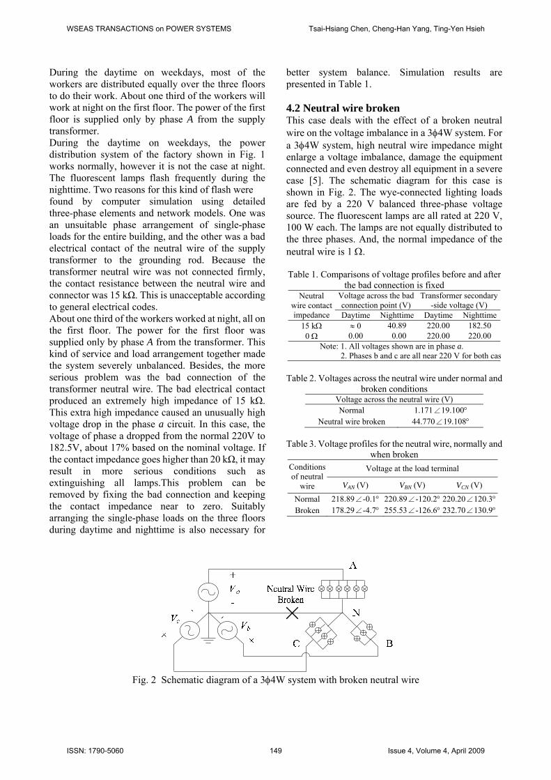
better system balance. Simulation results are presented in Table 1. 4.2 Neutral wire broken This case deals with the effect of a broken neutral wire on the voltage imbalance in a 3φ4W system. For a 3φ4W system, high neutral wire impedance might enlarge a voltage imbalance, damage the equipment connected and even destroy all equipment in a severe case [5]. The schematic diagram for this case is shown in Fig. 2. The wye-connected lighting loads are fed by a 220 V balanced three-phase voltage source. The fluorescent lamps are all rated at 220 V, 100 W each. The lamps are not equally distributed to the three phases. And, the normal impedance of the neutral wire is 1 Ω. Table 1. Comparisons of voltage profiles before and after
the bad connection is fixed Neutral
wire contact impedance
Voltage across the bad connection point (V)
Transformer secondary-side voltage (V)
Daytime Nighttime Daytime Nighttime15 kΩ ≈ 0 40.89 220.00 182.50 0 Ω 0.00 0.00 220.00 220.00
Note: 1. All voltages shown are in phase a. 2. Phases b and c are all near 220 V for both cas
Table 2. Voltages across the neutral wire under normal and
broken conditions Voltage across the neutral wire (V) Normal 1.171∠19.100°
Neutral wire broken 44.770∠19.108°
Table 3. Voltage profiles for the neutral wire, normally and when broken
Conditionsof neutral
wire
Voltage at the load terminal
VAN (V) VBN (V) VCN (V)
Normal 218.89∠-0.1° 220.89∠-120.2° 220.20∠120.3°Broken 178.29∠-4.7° 255.53∠-126.6° 232.70∠130.9°
Fig. 2 Schematic diagram of a 3φ4W system with broken neutral wire
WSEAS TRANSACTIONS on POWER SYSTEMS Tsai-Hsiang Chen, Cheng-Han Yang, Ting-Yen Hsieh
ISSN: 1790-5060 149 Issue 4, Volume 4, April 2009

For a system with an unbalanced three phase load arrangement, high neutral wire impedance will enlarge the voltage across the neutral wire, as shown in Table 2. The simulation result shows that the voltages of phases B and C at the load terminal raised to 255.53 V and 232.7 V, respectively, and gaining 16.15% and 5.77% based on rated voltage, respectively. These abnormally high phase voltages might damage the lamps in phase B and C, or hasten their replacement rates. On the other hand, the voltage in phase A was reduced from 220V to 178.3 V. That might cause the lamps to flash. If the broken neutral line is fixed, then the three phase voltages will go back to normal in near balanced status as shown in Table 3. Moreover, if the loads are distributed equally to the three phases this problem can also be removed or minimized. 4.3 Unsuitable capacitor bank installation For reducing preventable energy loss, utilities always require their customers to maintain the power factor within a narrow range, for example, 0.95 leading to 0.9 lagging. Penalties will apply to the electric fees of customers if their loads’ power factors run outside the limits. Installation of shunt capacitor banks is the most common and cheapest manner to improve the power factor. However, unsuitable installation may make it worse. This case is used to indicate the problem of unsuitable installation of a shunt capacitor bank. The schematic diagram for this case study is shown in Fig. 3. The supply transformer is rated at 150 kVA, 11.4 kV-380/220 V, and supplies a three-phase load of 105 kVA with power factor 0.7 lagging. The shunt capacitor bank to correct the poor power factor is rated at 20 kvar. The impedance of the shunt capacitor bank is 1.805 Ω per phase. A single-phase capacitor bank is connected to phase b to improve system power factor as shown in Fig. 3.
This kind of installation should make the system unbalanced. This unsuitable installation consumes extra real power of 34,422.57 W. That can be obtained by hand calculation as shown in (3). The suitable way to improve the system power factor for this case is to install a three-phase capacitor bank instead of a single-phase capacitor bank. The reason can be found in Table 4. This case indicates that the system balance should be considered when installing a capacitor bank to correct the system power factor for a three-phase power distribution system.
2 23 3 378.818 34,4264 4 1.805
= (W)ab
c
VX× ×
=×
(3)
4.4 Operation of three-phase motor under voltage imbalance The impacts of voltage imbalance on a delta-connected three-phase motor are explored in this case. A schematic diagram for this case study is shown in Fig.4. It is known that voltage imbalance not only decreases motor efficiency but also reduces its life cycle and herefore significantly increases at motor’s operation and maintenance costs [1, 3-4,7]. High VUR may make a motor operate inefficiency and fail frequently. In a practical case, the motors in a factory fail recurrently. Table 4. Electric fees for power factor correction by
suitable and unsuitable shunt capacitor bank
Installation Total power
consumption (W)
Electric fee (NT $ / h) Power factor
Before correction 73,306 130.130 0.7 Single-phase
capacitor bank 107,724 185.660 0.8
Three-phase capacitor bank 73,256 126.260 0.8
Note: 1. Electric fee = 1.7235 NT $/kWh.(NT $ means New Taiwan dollar) 2. Penalty is included in the electric fee, 3‰ for every 0.01 for power factor below 0.8.
Fig. 3 Schematic diagram for the case study of unsuitable capacitor bank installation
WSEAS TRANSACTIONS on POWER SYSTEMS Tsai-Hsiang Chen, Cheng-Han Yang, Ting-Yen Hsieh
ISSN: 1790-5060 150 Issue 4, Volume 4, April 2009

Table 5. Voltage and current profiles at the terminal of a three-phase motor operated under unbalanced conditions
Va (V) Vb (V) Vc (V) Ia (V) Ib (V) Ic (V) 276.7 266.8 261.7 643 750 651
ba−θ cb−θ ac−θ ba−θ cb−θ ac−θ 122 117 121 122 117 121
To find the reasons, some field tests and measurements were performed. The measurements included system voltages, currents, and powers for each phase. The measurement results show that the three phase loadings are considerably unbalanced. Sometimes, active loads are all in the same phase. That makes the system significantly unbalanced. The unequal loadings lead to a terminal voltage and a current imbalance of an unacceptable level as shown in Table 5. It is found that the voltage imbalance ratio reaches 3.16% and results in the winding temperature rising by 16.7% ~ 19.8% compared to that of a normal balanced case, as shown in Fig. 5. The temperature rises shown in Fig. 5 are obtained by hand calculation according to empirical rules that are commonly used by industry [2]. In Fig. 5, the d2% denotes one kind of VUR and is defined as the ratio of negative-sequence component
and positive-sequence component of the three-phase voltage under study. High VUR will overheat the motor windings, weaken the insulation, and reduce the motor life cycle, as shown in Fig.6 [8]. This case confirms that a good phase loading arrangement and system balance is very important for operating a three-phase motor efficiently. 4.5 Single-phase operation of three-phase motor The destruction of a three-phase inductive machine caused by the single-phase is presented in this section. Many reasons make a three-phase motor single-phase operation, such as three phase fuses burnout not at the same time or three poles of circuit breakers open not simultaneously. The single-phase operation causes recurrently a three-phase motor burnout [9-17]. Fig. 7 illustrates the normal condition of a three phase motor fed by a three-phase service. And, Fig. 8 shows the single-phase operation condition of a three-phase motor due to Phase A conductor of service line broken.
Fig. 4 Schematic diagram for measure voltage imbalance of a three phase motor
Fig. 5 Winding temperature rise due to voltage imbalance
WSEAS TRANSACTIONS on POWER SYSTEMS Tsai-Hsiang Chen, Cheng-Han Yang, Ting-Yen Hsieh
ISSN: 1790-5060 151 Issue 4, Volume 4, April 2009

The broken of service line make the three-phase motor operated under extremely unbalanced condition, that is the motor fed by single-phase power. The symmetrical component method can be applied to build an equivalent circuit to analyze this disallow condition, as show in Fig. 9. The three phase currents for the system shown in Fig. 8 can be represented by (4). The unbalanced three phase currents can be transferred to sequence quantities as shown in (5), (6), and (7). Assume the impedance of the positive-sequence and negative- sequence of the induction machine are Z and Z , respectively, the sequence voltages can then be represented as (8). Equation (10) can be obtained by substituting (9) into (8). Combined (8), (9) and (10), the positive- sequence current can be obtained as (11). The equivalent circuit of single-phase operation of three-phase motor can then be developed by (12), as show in Fig. 9. Finally, the abnormal operation currents in phases B can be represented as (12) or (13). In Fig.9, the upper and lower parts are the positive- and the negative-sequence circuits of a three-phase induction machine, respectively. The slips of the rotor to forward rotating magnetic field and to reverse rotating magnetic field are s and (2-s), respectively. Both balanced three-phase and unbalanced single-phase operation conditions are analyzed for comparison. The sample 7.5 kW, 380V induction machine has the rotor impedance of 0.6 j1.452 Ω, the stator impedance of 0.875j0.968 Ω, the core resistance of 526.5 Ω, and the flux impedance of 31.12 Ω. Under normal operation condition, the induction machine is fed by a balanced three-phase source and operated at its rated voltage and load. While the service line of phase A broken, the operation current of phase B and C increase sharply.
I 0I I (4)
I T I
I T I (5)
T1 1 11 a a1 a a
, T1 1 11 a a1 a a
(6)
I 0
I I
I I
(7)
V I Z
V I Z I ZV V I Z Z
(8)
V V V V
V V V V
V V V V
(9)
V V V V V
√ (10)
I
√V
Z Z (11)
I a I aI j√3I VZ Z
(12)
|I | |I |√
(13)
Fig. 6 Motor life cycle reduction under VUR of 3.163%
WSEAS TRANSACTIONS on POWER SYSTEMS Tsai-Hsiang Chen, Cheng-Han Yang, Ting-Yen Hsieh
ISSN: 1790-5060 152 Issue 4, Volume 4, April 2009

The abnormal currents will usually overheating or even burnout the windings of the induction machine. The simulation results are show in Table 6. This case indicates that single-phase operation will cause the windings of a three-phase induction machine overheating and burnout. Therefore, three-phase fuses or circuit breakers work simultaneous is very important to prevent this kind of problems. On the other hand, the operators in a factory or power station should confirm all three-phase motors have been shut down before
cutting the power off, otherwise it might cause a serious problem. Table 6. Winding currents of three-phase induction machineunder normal and abnormal operation conditions
Phase currents
Normal operation (A)
Single-phase operation (A)
Isa 15.618∠-31.226° 0.000 0∠ ° Isb 15.618∠-151.226° 23.351∠-126.210° Isc 15.618 88.77∠ 4° 23.351∠53.788°
Fig. 7 Three phase motor fed by a balanced power supply system
Fig. 8 Single-phase operation of a three-phase motor
bcV
bI
b
rR(2 - s)
rRscR
cR
sR
mjX
mjX
sjX
sjX rjX
rjX
c cI
sR
Fig. 9 Equivalent sequence circuit of single-phase operation of a three-phase induction machine
WSEAS TRANSACTIONS on POWER SYSTEMS Tsai-Hsiang Chen, Cheng-Han Yang, Ting-Yen Hsieh
ISSN: 1790-5060 153 Issue 4, Volume 4, April 2009

5 Conclusion Several cases have been used to confirm the impacts of voltage imbalance on systems and equipment. Voltage imbalance not only causes extra energy loss, but also causes safety problems for a system. To prevent voltage imbalance, the balance problem should be taken into account through all the planning, design, installation and operation stages. This paper displays some cases, with theoretical analysis and explanation, to make it easy to grasp the impacts of voltage imbalance on systems and equipment. The results are of value to engineers for better design, operation and maintenance of power distribution systems. References: [1] Jawad Faiz, H. Ebrahimpour and P. Pillay,
Influence of unbalanced voltage supply on efficiency of three phase squirrel cage induction motor and economic analysis, Elsevier Energy Conversion and Management, Vol. 47, No. 3, 2006, pp. 289-302.
[2] Cooper Bussmann, Motor Protection Voltage Unbalance and Single-Phasing, Progress Energy, 2003.
[3] Pragasen Pillay, Marubini Manyage, Loss of Life in Induction Machines Operating With Unbalanced Supplies, IEEE TRANSACTIONS ON ENERGY CONVERSION, VOL. 21, NO. 4, DECEMBER 2006, pp. 813 - 822.
[4] Siddique A, Yadava G.S., Singh B, Effects of voltage unbalance on induction motors, IEEE International Symposium on Electrical Insulation, 2004, pp. 26 - 29.
[5] Desmet, J., Sweertvaegher, I., Vanalme, G., Stockman, K., Belmans, R, Analysis of the neutral conductor current in a three phase supplied network with nonlinear single phase loads, IEEE Transactions on Industry Applications, Vol. 39, No. 3, 2003, pp. 448 – 453.
[6] Horton R, Warren T, Fender K, Harry S, Gross C.A, Unbalance protection of fuseless, split-wye, grounded, shunt capacitor banks, IEEE Transactions on Power Delivery, Vol. 17, No. 3, 2002, pp. 698 – 701.
[7] JULIO BARROS, MATILDE DE APRAIZ, RAMÓN I. DIEGO, A VI-based Measurement Instrument for Detection and Analysis of Power Quality Disturbances in Power Systems Using Wavelets, 7th WSEAS International Conference on Electric Power Systems, High Voltages,
Electric Machines, Venice, Italy, November 21-23, 2007.
[8] R. F. Woll, Comparison of Application Capabilities of U and T Rated Motors, IEEE Transactions on Industry Applications, Vol. IA-11, No. 1, 1975, pp. 34-37.
[9] ENRIQUE QUISPE, PERCY VIEGO, JUAN COGOLLOS, Effects of Voltage Unbalance on the Efficiency and Power Factor of Induction Motors: A Statistical Approach, ISSN 1109-2734. Wseas Transactions on Circuits and Systems. Statistical equations to evaluate the effects of voltage unbalance on the efficiency and power factor of a three-phase induction motors. Enrique Quispe. Percy Viego (Universidad de Cienfuegos). Juan Cogollos (Universidad de Cienfuegos). Vol. 4. No. 4. Brasil. Abril de 2005. pp. 234 – 239.
[10]L. REFOUFI, H. BENTARZI, F. Z. DEKHANDJI, Voltage Unbalance Effects on Induction Motor Performance, Proceedings of the 6th WSEAS International Conference on Simulation, Modelling and Optimization, Lisbon, Portugal, September 22-24, 2006.
[11]Kanwarjit Singh Sandhu, Vineet Chaudhary, Steady State Modelling of Induction Motor Operating with Unbalanced Supply System, WSEAS TRANSACTIONS on CIRCUITS and SYSTEMS Issue 2, Volume 8, February 2009.
[12]Ching-Yin Lee, Effects of Unbalanced Voltage on the Operation Performance of a Three-phase Induction Motor, IEEE Transactions on Energy Conversion, Vol. 14, No. 2, June 1999, pp. 202 – 208.
[13]Piotr Gnaci´nski, Windings Temperature and Loss of Life of an Induction Machine Under Voltage Unbalance Combined With Over- or Undervoltages, IEEE TRANSACTIONS ON ENERGY CONVERSION, VOL. 23, NO. 2, JUNE 2008, pp.363-371.
[14] James H. Dymond, Nick Stranges, Operation on Unbalanced Voltage: One Motor’s Experience and More, IEEE TRANSACTIONS ON INDUSTRY APPLICATIONS, VOL. 43, NO. 3, MAY/JUNE 2007, pp.829-837.
[15]Pragasen Pillay, Peter Hofmann, Marubini Manyage, Derating of Induction Motors Operating With a Combination of Unbalanced Voltages and Over or Undervoltages, IEEE TRANSACTIONS ON ENERGY CONVERSION, VOL. 17, NO. 4, DECEMBER 2002, pp.485-491.
[16]Antonio Marcus Nogueira Lima, Cursino Brand˜ao Jacobina, Eurico Bezerra de Souza Filho, Nonlinear Parameter Estimation of
WSEAS TRANSACTIONS on POWER SYSTEMS Tsai-Hsiang Chen, Cheng-Han Yang, Ting-Yen Hsieh
ISSN: 1790-5060 154 Issue 4, Volume 4, April 2009

Steady-State Induction Machine Models, IEEE TRANSACTIONS ON INDUSTRIAL ELECTRONICS, VOL. 44, NO. 3, JUNE 1997, pp.390-397.
[17]Ching-Yin Lee, Bin-Kwie Chen, Wei-Jen Lee, Yen-Feng Hsu, Effects of Various Unbalanced
Voltages on the Operation Performance of an Induction Motor under the Same Voltage Unbalance Factor Condition, IEEE Industrial and Commercial Power Systems Technical Conference, May 1997 , pp.51-59.
WSEAS TRANSACTIONS on POWER SYSTEMS Tsai-Hsiang Chen, Cheng-Han Yang, Ting-Yen Hsieh
ISSN: 1790-5060 155 Issue 4, Volume 4, April 2009