RESEARCH MEMORANDUM - NASA · · 2014-07-15RESEARCH MEMORANDUM ... with Bredt, perhaps the first...
71
RESEARCH MEMORANDUM A COMPARJTIVE ANALYSIS OF THE PERFORMANCE OF LONG-RANGE HYPERVELOCITY VEHICLES By Alfred J. Eggers, Jr., H. Julian Allen, and Stanford E. Neice t- -r - -L COPY 287 ._ - -..- RM A54Ll.O Ames Aeronautics-l. Laboratory Moffett Field, Calif. e NATYONAL ADVISORY COMMITTEE FOR AERONAUTICS WASHINGTON March 24, 1955 . https://ntrs.nasa.gov/search.jsp?R=19930093743 2018-06-16T14:11:03+00:00Z
Transcript of RESEARCH MEMORANDUM - NASA · · 2014-07-15RESEARCH MEMORANDUM ... with Bredt, perhaps the first...

RESEARCH MEMORANDUM A COMPARJTIVE ANALYSIS OF THE PERFORMANCE OF
LONG-RANGE HYPERVELOCITY VEHICLES
By Alfred J. Eggers, Jr., H. Julian Allen, and Stanford E. Neice
t- -r 8
-
-L COPY 287
._ - -..- RM A54Ll.O
Ames Aeronautics-l. Laboratory Moffett Field, Calif.
e
NATYONAL ADVISORY COMMITTEE FOR AERONAUTICS
WASHINGTON March 24, 1955 .
https://ntrs.nasa.gov/search.jsp?R=19930093743 2018-06-16T14:11:03+00:00Z

l
NAC!A RM A54LlO
TABLE OF CONTENTS
k3llMmaY .............................. INTRODUCTION ........................... ANALYSIS . . .
GeneA c+;i:era;&i ........ ...... .
Powered Flight and the Breguet Range Eqia&. ........................... .. Motion in .Unpowered Flight ..................
Balli&ic trajectory .................. Skip trajectory ..................... Glide trajectory ....................
HeatinginUnpoweredFlight ................. General considerations ................. Ballistic vehfcle .................... Skipvehicle ...................... Glide vehicle ......................
DISCUSSION .... Perfo4n~e.o~ ;[&e&elocity Vechicles .............................
Motion ......................... Aerodynamicheating. ..................
Comparison of Hypervelocity Vehicles With the Supersonic Airplane ..........................
CONCLUDING m AND SOME DESIGN CONSIDERATIONS FOR GLIDE VEHICLES
APPENDIXA - NOTAT;ON: : : : : : : : : : : : : : : : : : : : : : : Subscripts ..........................
APPENDIXB - SIMPLIFYINGASSUMFTIONS IN=ANALYSIS OFTKE GLIDETF&JECTQRY
APPENDIX c - 9T.E tiT;ON . .cFl~,~~ .. iLjDj~* .....
CONICAL MISSILES .... APPENDIXD-
mmk;N.O; &&; k;O;GD.a& ;to;&.
VEHICLES ...................... . ...... Radiation of 3eat From Glide Vehicles ...... . Radiative and Convective Heat Transfer Associated With
....
Skip Vehicle ........................ APPENDIXE - DE-ION OF m RATIO OF (L/D)- FOR A FLAT
PLATETO(L/D)- FORACONE .................. REFERENCES ............................ FIGURES ..............................
Page
1 2
i
* 2
86 12 14 14 18 19 22 26 26 27 27
30
;t 36
37
39
44 44
45
49
z:

NACARM A54LlO
NATIONAL ADVISORY COMMITTEE FOR AERONAUTICS
RESEARCH MEMORANDUM
A COMPARATIVE ANALYSIS OF TRE PmRMANCE OF
LONG-RANGE BYPERVEZOCITY VEEDCIES
By Alfred J. Eggers, Jr., H. Julian Allen, and Stanford E. Neice
SUMMARY
4 '-
d
Long-range hypervelocity vehicles are studied in terms of their motion in powered flight, and thefr motion and aerodynamic heating in unpowered flight. Powered f-light is analyzed for an idealized propulsion system which rather closely approaches present-day rocket motors. Unpow- ered flight is characterized by a return to earth along a ballistic, skip, or glide trajectory. Only those trajectories are treated which yield the maximum range for a given velocity at the end of powered flight. Aero- dynamic heating is treated in a manner similar to that employed previously by the senior authors in studying ballistic missiles (NACA RM A53D28), with the exception that radiant as well as convective heat transfer is considered in connection with glide and skip vehicles,
The ballistic veh3cle is found-to be the least efficient of the several types studied in the sense that it generally requires the highest velocity at the end of powered flight in order to attain a given range. This disadvantage may be offset, however, by reducing convective heat transfer to the re-entry body through the artifice of increasing pressure drag in relatfon to friction drag - thatis,byusingabluntbody. Thus the kinetic energy required by the vehicle at the end of powered flight may be reduced by minimizing the mass of coolant material involved.
The glide vehicle developing lift-drag ratios in the neighborhood of and greater than 4 is far superior to the ballistic vehicle in ability to convert velocity into range. It has the disadvantage of having far more heat convected to it; however, it has the compensating advantage that this heat can in the main be radiated back to the atmosphere. Con- sequently, the mass of coolant material may be kept relatively low.
The skip vehicle developing lift-drag ratios from about 1 to 4 is found to be superior to comparable ballistic and glide vehicles in con- verting velocity into range. At lfft-drag ratios below 1 it is found to be about equal to comparable ballistic vehicles while at lift-drag ratios
.
2 NASA RM A54LlO
above 4 it is about equal to comparable glide vehicles. The skip vehicle I experiences extremely large loads, however, and it encounters most severe aerodynamic heating. I
As a final performance consideration, it is.shown that on the basis of equal ratios of mss at take-off to mass at the end of powered flight, -. the hypervelocity vehicle compares favorably tith the supersonic airplane for ranges ti the neighborhood of and greater than one half the circum- ference of the earth. In the light of this .and previous findings, it is concluded that the ballistic and glide vehicles have, in addition to the advantages usually ascribed to great speed, the attractfve possfbflity of providing relatively efficient long-range flight.
Design aspects of the glide vehicle are touched on briefly. It is argued from considerations of motion and heating that vehicles of this type which fly at hypersonic speeds to impact might profitably consist of blunt-nosed bodies of revolution stabilized by a conical flare at the base and controlled by deflectable sections or the afterbody. In the event that wtigs are necessary to provide acceptable low-speed character- istics, it is indicated that they should have highly swept, rounded lead-
L- .
ing edges ti order to alleviate the local drag penalty.
heattig problem &Lth minimum v
INTBODUCTION
It is generally recognized that hypervelocity vehicles are especially .- suited for military application because of the great difficulty of defend- ing against them. It is also possible that for long-range operation, hypervelocity vehicles may not be overly extravagant in cost. A satellite vehicle, for example, can attain arbitrarily long range tith a finite speed and hence finite energy input. E. Sanger was among the first to recognize this favorable colinection between speed and range (ref. 1) and was, with Bredt, perhaps the first to exploit the speed factor ti design- ing a long-range bomber (ref. 2). This design envisioned a rocket-boost vehicle attaining hypervelocity speeds at burnout and returning to earth along a combined skip-glide trajectory. -Considerable attention was given to the propulsion and motion analysis; however, little attention was given to what is now considered to be a principal problem associated with any type of hypersonic aircrsft, namely that of aerodynamic heating. In addition, the category of expendable vehicles, perhaps best characterized by the ballistic missile, was nolt treated.
Since the work of Sanger and Bredt there have been, of course, many treatments of long-range hypervelocity vehicles in which the propulsion, motion, and heating problems have been studied in considerable detail. However, these analyses have been devoted in the.main to particular designs . and are not intended to reveal, for example, the relative advantages and
NACA RM A54LlO 3
disadvantages of ballistic-, skip-, and glide-type vehicles. Furthermore, it appears that the extent to which these vehicles can compete on a simple efficiency basis with lower speed aircraft of either the expendable or nonexpendable type has not been well. established.
It has therefore been undertaken in the present report to make a comparative analysis of the performance of hypervelocity vehicles having ballistic, skip, and glide trajectories. An idealized propulsion system, whose performance is rather closely approached by present-day rocket motors, is assumed. The motion analysis is sFmplified by treating, for the most part, only optimum trajectories yielding the maximum range for a given inftial kinetic energy per unit mass in the unpowered portion of night. Aerodynamic heating is treated in a manner analogous to that employed by the senior authors Tn studying ballistic missiles (ref. 3) tith the exception that radiant heat transfer, as well as convective heat transfer, is considered in the treatment of glide and skig vehicles. The efficiencies of these vehicles are compared with those determined by the method of &ha&erg (ref. 4) for supersonic aircraft.
ANALYSIS
General Considerations
In the following analysis of long-range hypervelocfty vehicles, only flight in planes contafning the great circle arc between take-off and landing is considered. The fldght is thought of in two phases: (a) the powered phase in which sufficient kinetic energy, as well as control, is imparted to the vehicle to bring it to a prescribed velocity, orientation, and position in space; and (b) the unpowered phase, in which the vehicle travels to its destinatfon under the influence of gravity and aerodmic forces.
The analyses of motion and aerodynamic heating during unpowered flight will, of necessity, djffer widely for the several types of vehicles under consideration. On the other hand, motlon in the powered phase is con- veniently treated by a method common to all vehicles. The study of powered flQht and its relation to range-is therefore taken as a starting point in the analysis. The mathematical symbols employed in the analysis are listed Fn Appendix A.
Powered Flight and the Breguet Range Equation
In this part of the study, the following Hmplifying assumptions are made: (a) aerodynamic heating can be neglected on the premise that high

4 NACA RM A54LlO-
flight speeds are not attained until the vehicle is in the rarefied upper atmosphere;' (b) sufficient stability and control is available to provide proper orientation and positioning of the vehicle in space; (c) the dis- tance traveled while under power is negligible by comparison to the over- all range; and finally, (d) the thrust is very large compared to the retarding aerodynamic and gravity forces. In terms of present-day power plants, the last assumption is tantamount to assuming a rocket drive for the vehicle.
The velocity at burnout of the first stage of a multistage rocket (or the final velocity of a single-stage rocket) can then be expressed is (see, e.g., ref. 5):
where the initial velocity
(1)
-I
-- --
is taken as zero. In this expression, mi and the vehicle at the beginning and ending of mfl represent the mass of
first-stage flight, and vfl = Vfl/Vg where Vs = & = 25,930 feet per second is the satellite velocity at the surface of the earth. The coefficient g is the acceleration due to gravity and is, along with the specific impulse I, considered constant in this phase of the anal- ysi~.~ The final velocity of the vehicle at the end of the N stages of powered flight can be expressed as
& -
'd
where the initial mass of any given stage differs from the final mass of the previous stage by the amount of structure, etc., jettisoned.
Now let us define an equivalent single-stage rocket having the same initial and final mass as the N-stage rocket and the ssme initial and final velocity. There is, then, an effective specific impulse defined by
%l?his assumption is in the main permissible. A possible exception occurs, however, with the glide vehicle for which heat-transfer rates near the end of powered flight can be comparable to those experienced in unpowered gliding flight.
?6oth g and I actually vary with altitude, of -course, but for the-. powered flight trajectories of interest here the variations are small and it is permissible to use constant average values of these quantities. .
NACA J3M A54LlO
whereby equation (2) can be written as
5
(31
(4)
A
i
The effective specific impulse Ie is always somewhat less than the actual specific impulse, but for an efficient design they are very nearly equal. Throughout the remainder of. the analysis the effective impulse I, will be used.
Equation (4) might be termed the. "ideal power plant" equation for accelerated flight because, when considered in combination with the asswnptions underlying its development, attention is naturally focused on the salient factors leading to maximum increase in velocity for given expenditure of propellant. Thus the thrust acts only in overcoming inertia forces, and the increase in vehicle velocity is directly proportional to the exhaust velocity (gI) for the propellant.
Now we recognize that an essential feature of the hypervelocity vehicles under study here is that they use their velocity (or kinetic energy per unit mass) to obtain range. For this reason, equation (4) also constitutes a basic performance equation for these vehicles because it provides a connecting link between range requirements and power-plant requirements.
In addition to comparing various types of hypervelocity vehicles,- our attention will also be focused upon comparison of these.vehicles with lower speed, more conventional types of aircraft. For this purpose it is useful to develop an alternate form of equation (4). We observe that the kinetic energy imparted to the vehicle is
This energy is Equated to an effective work done, defined as the product of the range travel,ed and a constant retarding force. (Note that the useful kinetic energy at the end of powered flight is zero.) This force is termed the "effective drag" De. Thus
.

6
DeFt =+Vf2 (5)
NACA RM A54LlO
where R is flight range measured along the surface of the earth. Similarly, we may define s.n."effective lift" Le, equal to the final weight of the vehicle .
Le = Wf = mfg
from which it follows that equation (5) may be written as
R= 03
.
.
where (L/D) e is termed the "effective lift-drag ratio." Combining equati,ons (4) and (6), we obtain
R = ($)eIeVeln (2)
where Vf Ve =2
(7) A
2.-
(8)
and represents an "effective" flight velocity of the vehicle. Equa- tion (7) will prove useful in comparing hypersonic vehicles with conven- tional aircraft because of its analogy to the Breguet range equation,
(9)
It will also prove useful to have equation (7) in the dimensionless form obtained by dividing through with ro, the radius of the earth. In this case we have
(10)
where # is the range in radians of arc traversed along the surface of the the earth.
-
Motion in Unpowered Fl&&t
Ballistic trajectory.- In studying the motion of long-range vehicles in this trajectory, advantage is taken of the fact that the traverse through the earth's atmosphere generally forms only a small part of the total trajectory. Therefore, the deflection an&deceleration encountered in the re-entry phase (discussed in detail in ref. 3) are neglected in

NACA RM A54LlO CL.& -~.d.LFE 7
the computation of the total range. With the added simplification that the contribution to range of the powered phase of flight is negligible, the ballistic trajectory becomes.one of Kepler's planetary ellipses, the major axis of which bisects the total angle of arc Q traveled around the earth (see sketch). For the trajectories of interest here (vfll), the
*far focus of the ellipse is at the mass center of the earth. For purposes of range computation, then, the ballistic vehicle leaves and returns to the earth's surface at the same absolute magnitude of velocity and inci- dence9 (see sketch).
Earth’s surface
The expression for range follows easily from the ellipse (see, e.g., ref. 6) and can be written
8 =J$ sin Bfcos Bf
=2tan-= 1 ( I) p- COS20f
equation of the
(11)
where the angle of incidence 8f is considered positive. In order to determine the optimum trajectory giving maximum range for a given velocity . Vf, equation (XL) is differentiated with respect to Bf and equated to 0, yieLding
Vf2 Vf2 = v2 = 1 - tan2Gf 6
(12)
aRotatlon of the earth is neglected ti thfs and all other phases of the analysis.
8 NACA RM A54LlO
Equations'(U) and (12) have been employed to determine-velocity as a function of incidence for various values of range and the results are presented in figure 1.' The Yninimum velocity line" of figure 1 cor- responds to the optimum trajectories (eqs. (12)).
The effective lift-drag ratios can easily be calculated for optimum ballistic vehicles using equation (6) in combination with the information of figure 1. The required values of (L/D), as a function of range are presented in figure 2. .._
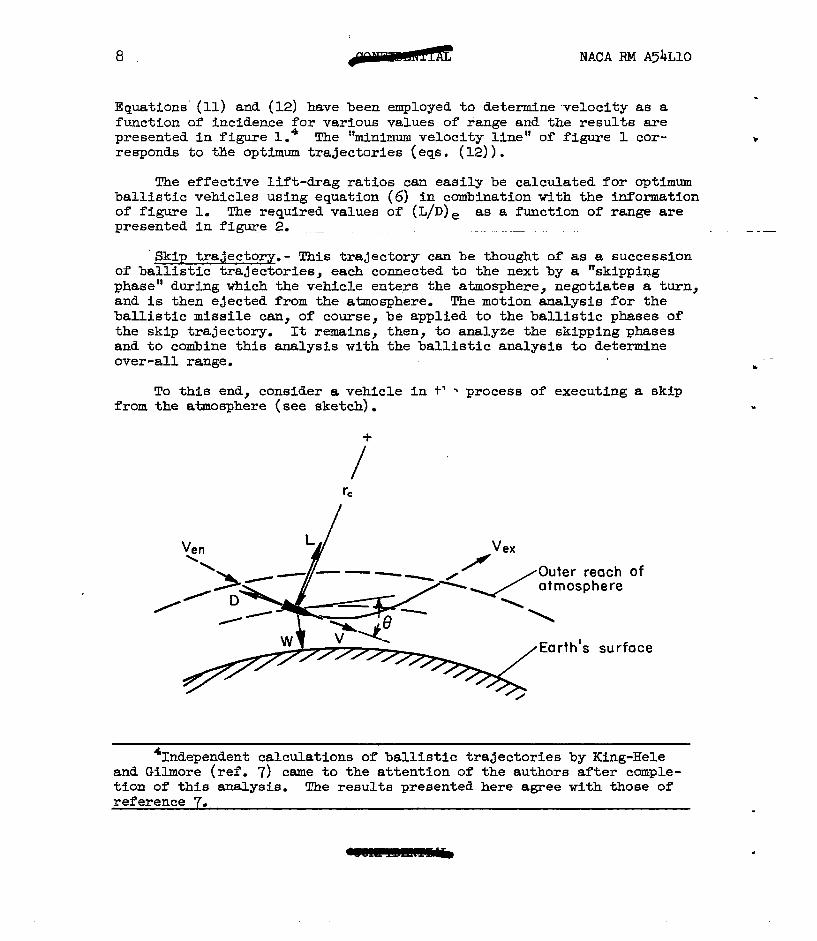
Skip trajectory.- This trajectory can be thought of as a succession of ballistic trajectories, each connected to the next by a "skipping phase" during which the vehicle enters the atmosphere, negotiates a turn, and is then ejected from the atmosphere. The motion analysis for the ballistic missile can, of course, be applied to the ballistic phases of the skip trajectory. It remains, then, to analyze the skipping phases and to combine this analysis with the ballistic analysis to determine over-all range.
To this end, consider a vehicle in t' % process of executing a skip from the atmosphere (see sketch).
Vex
Earth’s surface
'Independent calculations of ballistic trajectories by King-Hele and Gilmore (ref. 7) came to the attention of the authors after comple- tion of this analysis. The results presented here agree with those of reference 7.
NACA RM A54LlO 9
The parametric equations of motion in directions perpendicular and parallel to the flight path 6 are, respectively,
V' CL y A
mV2 - mg COB e =- rc
-CD NT2 TA+mg sin6 =mg
(13)
where rc is the local radius of curvature of the flight path, 8 is the local inclination to the horizontal (positive downward), P is the local air density, and CL and CD are the Lift and drag coeffYLcient6, respec- tively, based on the reference area, A, of the aircraft.
In the turning process, aerodynamic lift must ,obviously predominate over the gravity component, mg co6 8. By analogy to the atmospheric re-entry of ballistic missiles (see ref. 3), aerodynamic drag generally predominates over the gravity component, mg sin 8. Moreover, the inte- grated contribution to velocity of this gravity component during descent in a skip is largely balanced by an opposite contribution during ascent. For these reasons we will idealize the analysis by neglecting gravity entirely.5 In this case equations (13) reduce to
F! 1 CLpV2A = -me 2
I 714) - $ CDpV2A dV
=mdt I
where de/d6 = - $ to the accuracy of this analysis.
Now we assume an isothermal atmosphere, in which case
p = poe+Y (15)
where p. and B are constants, and y = (r - r,) is the altitude from sea level (see ref. 3 for discussion of accuracy of this assumption).
%his approach is analogous to the classical treatment of impact * problems in which all forces exclusive of impact forces (aerodynamic forces in this case) are neglected as being of secondary importance. Gravity is shown to be of secondary mortance in figure 3 where the trajectory : results obtainable from equations (13) and (14) are presented for the first skipping phase of an L/D = 2, @ = 1 skip missile. .
10 NACA RM A54LlO
.
Noting that dy/ds = -sin e, we combine the first of equations (14) tith . equation (15) to yield
.
CLPOA - e+ydy 2m = sin 8 de
This expression can be integrated to give
SLPOA 2Pm
e-b = co6 8 - co6 @en (17)
where p is taken as zero at the altitude corresponding to the effective "outer reach" of the atmosphere. Equation (17) points out an Important feature of the ship path; namely, COB 8 is a single-valued function of altitude. Since 8 proceeds from positive to negative values, it is
evident that
(18) -
where the subscripts en and ex refer to.atmospheric entrance and exit conditions, respectively, and the numbers n - 1 and n refer to suc- cessive ballistic phases of the trajectory. Now since
dV dV 1 dV2 -=v-=-- dt ds 2 ds
equations (14) may be combined to obtain
ldVa V2 de w-z:- 2 ds L/D.ds
which, for constant L/D, can be integrated to yield
Vexn
eeXn - eenn,l
L/D t, =e
(19)
With the aid ofequation (IS), this expression may be written

NACA F&f A54LlO 11
veXn - Snn-l
V =e L/D e%-l
(21)
which relates the velocities at the beginning and end of a skip to the lift-drag ratio and the entrance angle of the vehicle to the.earth's atmosphere. From equation (18) it follows further that the entrance angle for each skip in the trajectory is the same, so that
eenn = ee%-l = l l l =
@ f
and hence equation (21) becomes
vexa =f
-L/D V
=e (22) enn-x
We now combine this I?esult of the skip analysis with that of the ballistic analysis to obtain the total flight 'range. From equation (II), the range of the nth ballistic segment of the trajectory is
=2tan-= sin efc06 ef
% [ I % 2 ( >
- - V
c0s2ef exn
(23)
Consistent with the idealization of the skipping process aa an impact problem, we neglect the contribution to ras@;e of each skipping phase so that the total range is simply the sum of the ballistic contributions. From equations (22) and (23) this range is then
u? =J& = 1 'Pn = 2ztan-1 ;zfefcos ef II=0 n=o
c J
.L/D - - c062ef
Vf"
(24)

12 NACA RM A54LlO
From this expression we see that for any given velocity at the end of powered flight there is a definite'skipping angle which maximizes the range of an aircraft developing a partfcular lift-drag ratio. These skipping angles have been-obtained with the aid of.an IBM.CPC, and the corresponding values of Vf as a function of range for various L/D are presented in figure 4. using equation (6)
Corresponding values of (L/II), have been obtained and the results are shown in figure 5.
Glide trajectory.- The trajectory of the glide vehicle is illustrated in the accompanying sketch. As in the previous analyses, the distance covered in the powered phase will be neglected in the determination of total range.
Earth’s surface
The parametric equations of motion normal and parallel to the direc- tion of motion are the relations of equations (13) rewritten in the form
L- mV2 mg co6 8 = - - rC
1 (25)
-D + mg sin e = m g J
Under the assumption of small inclination angle 8 to the horizontal (thus cos 8 Z 1, sin 0 2 e), constant gravity acceleration (f.e., and noting the following relations
t
.

NACA RM A54LlO 13
dV av -- 1 dV2 z=vz=2ds 1 ‘=GLgA rc!
d$- -= ds
COB 8 t 1 r r0
equations (25) can be written in the forms
L = mV2 g + mV2 ds mg-K
i
(26)
(27)
Dividing the first of equations (27) by the second yields the following differential equation I
(28)
But, as is demonstrated fn Appendix B, the terms $ gt3 and V2 $ may be neglected so that equation (28) reduces to
dV2 -gyy-&p2+$$=0 ( 29)
Since vs2 = @To
L equation (29) can be integrated for constant 5 to give the velocity in nondimensional form as
(30) l

14 NACA RM A54LlO
This expression gives velocity as a function of range for what Sanger (ref. 2) has termed the equilibrium trajectory - that is, the trajectory for which the gravity force is essentially balanced by the aerodynamic lift and centrifugal force, or
L i =1 -F (31)
It follows from equation (25) that velocity can be expressed in the form
-2 v = 1 1 + CLw2P
m3
(32)
Now it is intuitively obvious that as the maximum range is approached, L/W+1 and hence T2 becomes small compared to one (see eq. (31)). In this event it follows from equation (30) that the maximum range for the glide vehicle is given by
The relation between velocity and range has been determined with equation (33) for various values of L/D and the results are presented in figure 6. Corresponding values of (L/b), have been obtained using equation (6) and are presented.in figure 7.
These considerations complete the motion analysis and attention is now turned to the aerodynamic heating of the several types of vehicles under consideration.
Heating in Unpowered Flight
General considerations.- Three aspects of the aerodynamic heating of hypervelocfty vehicles will be treated here; namely,
1. The total heat input
2. The maximum time rate of average heat input per unit area
3. The maximum time rate of local heat input per unit area .
J NACA RM A54LlO 15
.
Total heat input is, of courBe, an important factor in determining over-all coolant weight, whether the coolant be solid (e.g., the strut- turd, liquid, or gas, or a comibinatfon thereof. The maximum time rate of average heat input per unit szea cm determine peak average flow rates in the case of fluid coolants and may dictate over-all structural strength in the event that thermal stresses predominate,
Excessive local heat- is, of courBe, a serious problem with hyper- velocity vehicles. This problemmay vary depending upon the type of the vehicle. Thus, for the ballistic vehicle, an important local shot spot" is the stagnation re@on of the nose, while for the skip or glide vehicle attention may also be focused on the leading edges of planar surfaces used for developing.lfft and obtaining stable and controlled flight. In this analysis attention is, for the purpose of sfmplicity, restrfcted to the What spot" at the nose. In particular, we consider the maximum tk.ue rate of local heat iuput per unit area because of its bearing on local coolant flow rates and local structural strength.
It is undertaken to treat only convective heat transfer at this stage of the study. As till be demonstrated, radiant heat transfer from the surface should not appreciably influence convective heat transfer to a vehicle. Therefore, alleviating effects of radiation are reserved for attention fn the discussion of particular vehicles later in the paper. This a~~aly~i~ is further.BUplified by making the assumptions that
1. Effects of gaseous imperfections may be neglected
2. Shock-wave boundary-layer interaction may be neglected
3. Prandtl number is unity
4. Reynolds analogy is applicable
These aBBUEptiOnB are obviously not permissible for ~u1 8cCU?Cate qUnti- tative study of a specific vehicle. Nevertheless they ShOtid not inval- idate this comparative analysis which is only intended to yield. informa- tion of a general nature re ng the relative merits and problems of different types of vehicle r- see ref. 3 for a more complete discussion of these aBBLIf@iOnB in connection with ballietic vehicles).
In calculating convective heat transfer to hypervelocity vehicles, the theoretical approach taken in reference 3 for ballistic vehicles is, up to a point, quite general and can be employed here. baBiB Of the foregoing~aBBumptions,
Thus, on the it follows that for large Mach numbers,
the difference between the local recovery temperature and wall tempera- ture can be expressed as
( 34)

16 RACA RI4 A54LlO
where Tr fs the recovery temperature, Tw is the wall temperature, s is the specific heat at constant pressure, and the subscript 2 denotes local conditions at a point on the surface.
It is clear, however, that the walls of a vehicle should be maintained sufficiently cool to insure structural integrity. It follows in this case that, the recovery temperature at hypervelocities till be large by compar- ison to the wall temperature and equation (34) may be simplified to read
v2 Trl = - 2%
(35)
To the accuracy of this analysis, then, the convective heat transfer is independent of wall temperature. Therefore, as previously asserted, radiant heat transfer should not appreciably influence convective heat transfer and the one can be studied independently of the other.
Row, according to Reynolds analogy, the local heat-transfer coef- ficient h2 is, for a Prandtl number of unity, given by the expression
(36)
where cFl ia the local skin-friction coefficient based on conditions just outside the boundary layer. With the aid of equations (35) and (36) the time rate of local heat transfer per unit area,
dE xii- - hZ(Tr - Tw)~
can be written as
dE v2 -- dt - 4cp ( ~pPplv~ >
(38)
Equation (38) can be integrated over the surface of a body to yield the time rate of total heat input-as follows
dQ dt= s z ds = i pv%F’s
S (39)

NACA RM A54LIO 17
. wherein %I is set equal to Cp and
. CF’ =A
S s S
The parameter CFt is termed the "equivalent skin-friction coefficient" and till be assumed constant for a particular vehicle. From equation (39) we can obtain two alternate forms which will prove useful; nemely, the altitude rate of total heat input defined by
dQ -= dy v Bii 8f dt
dQ _ ov=?F's - 4f
.
1 and the range rate of total heat input defined as
dQ 1 a, pv=cF’ s
d( rocp) = V COB Of dt 4 COB 8f
( 41)
The total heat input may be obtained by integration of equations (39), (41) or (42), depending upon the particular variable used.
The time rate of average heat input per unit area may be obtained from equation (39) as
w3v. l&Q -=sdt=T dt ' &%p'
Consider next the local convective heat transfer in the region of the nose. The tfme rate of local heat 2.nput per unit area was determined in reference 3 under the assumptions that viscosity coefficient varies as the square root of the absolute temperature, and that flow between the bow shock wave and the sta@ation point is incompressible. In this case it was found that6
%hile this expression is no doubt in error due to neglecting com- pressibility effects, nevertheless it is a useful guide in studying the local heat-transfer problem. (See ref. 3 f6r more complete discussion of this matter.)

18 NACA R&l A54LlO
% -= dt 6.8XlO+J$ vs (44)
where a is the radius of curvature of the body at the stagnation point.
With these relations we are now in a posltion to study the heating of the several types of vehicles of interest.
Ballistic vehicle.- The heating-for this-_case..has already been analyzed in reference 3. Only the results will be given here.
The ratio of the total heat input to the iaitial kinetic energy wae found to be
,,, .
For the "relatively light missile," which is of principal interest here,
CDooA -pm sin Bf
e <<l
and equation (45) reduces to
1 Q :hCFt”
5 mVf2 2 %A
(4-a
(47)
The time rate of average heat Input per unit area was found to be
f&V CF'PoVfS aCDooA e-BY
l&L -=- dt S dt 4
e-pyee2flm sin ef
which has the maximum.value
(W
(49)
at the altitude
.
lU.CA RM A54LlO 19
Ya = + In t
3cDpoA 28m > sin 0-f
(50)
Equation (49) applies, of course, only if the altitude of occurrence is above ground level. If the value of ya is negative then the maximum rate will; of course, occur at sea level.
The time rate of local heat input per unit area to the stagnation region of the nose was found to be
*DP~A 'PY mS
e
dt= 6.8~10'~ 2l3m sin ef
having a maximum value of
(.)- = (-)yb = 6.%xm-~~~f' (52)
occurring at the altitude
(51)
(53)
If the value of yb is negative, then the maximum value OCCUTB at ground level.
Skip vehicle.- With the aid of equation (17), the density at any point in a given skipping phase is found to be .
P = poesPY = *m q (COS 8 - cos ef) (54)
where it is to be recalled that 8 @f* The corresponding velocity is obtained by integrating equatioEntyg) for constant L/D, yielding

20 NACA RM A54LlO
ef-8
V = V,,e-m (55)
By SUbBtitUtiOn of equations (54) and (55) into equation (39), the time rate of total heat fnput at any point in a skipping phase can be expressed &B follows:
3(ef-e) ‘(COB 8 - CO6 ef)e L/D (56)
Row, recalling that = V, the first of equations (14) may be com- bined with equation (17
de at= -pv( CO6 8 - COB ef) (57)
Inasmuch as V,, = Vex for any ballistic phase, it then follows from equation (22) that
(ven) n (Ven) n
(Ven)n,l = vf = e
-(n-i) g (58)
With the aid of equations (57) and (58), equatfon (56) can be integrated to give the total heat input for a given skippfng phase. Thus we obtain
Qn
$ mVf2 e
. (59)
where n refers to the ballistic phase subsequent to the given skipping phase.
The total heat input for the entire trajectory can be obtained by summing up the heat inputs for each separate skipping phase. Performing this operation yields
I'UCA RM A54LlO 21
dLzrn Ql +ef
2 mVf2 c =LcFIs 1-e -L/D
n=L+mVf2 2 W ( > r
e- (n-d 2
(W
n=l
The summation on the right side of equation (60) represents a geometric series which can readily be evaluated. The total heat input for the entire trajectory then becomes
which is identical to the result obtained for the light ballistic missile (es. (47)).
The tkne rate of average heat input per unit area ie obtained by dividing equation (56) with the surface area, thus yielafng
mav 1 CFt Bm sbf-8)
-=--- dt 2 c+ L/D ven S(~o~ 8 - COB ef)e L/D 62)
It can be shown that this expression has a peak value at a point in the skip, ear given by
L/D ( co$ 8, - COB ef) = - sin e 3 a
or
8, = tan -13 - sin-= cos ef
L/D jm ( 63)
From equation (22) it can be concluded that the maximum heat-transfer rate will occur in the first slsip where Ven = Vf; consequently,

22 NASA RM A54LlO
4 Q-f-B,) $m %’
Vfssin e,e L/D = 6 a (64)
The time rate of local heat input per unit area in the stagnatiop re&on of the nose is obtained by introducing equations (54) and (55) into equation (44) with the following result:
WE; -= dt
Of 4 1/=
( cos 8 - COB ef) l/2 v,,’ e L/D (65)
Equation (65) has a peak value at a point eb in a skip given by
L/D (COB eb - CO8 ef) = - 6
sin f3b
or
It is clear in this case also that the heat-transfer rate will have its maximum value in the first skipping phase where the velocities are highest. Since V,, = v-f in the first skip, equation (65) becomes
= 6.0x10-~
a( ef ‘eb) Vfae
- L/D
Glide vehicle,- From equations (30) and (32), the density at a point in the glide trajectory is found to be

NACARMA54LlO
p= - (1 - Q2,eJ
c$$ 1 - (1 - Q2)eJ
23
where
By substitution of equations (30) and (68) into equation (39), the the Pate of total heat input cam be expressed as
ii2 =&%t- [I L/2
2 w L/D -vf21eJ - (1 - Tf2)eJ 1 (691
Now with the aid of equatfons (30) and (33), equation (69) can be inte- grated over the limits of the glide trajectory to yield the total heat input in terms of the inftial kinetic energy as
(701
which expression is identical with that obtatied for the skip vehicle (eq. (61)) and for the light ballistic vehicle (eq. (47)).
Now the tFme rate of average heat input per unit area is found by dividing equation (69) .tith the surface area, thus yielding
L/2 1 - (1 - Tf2)eJ] (71)
It follows from this expression that the maximu.u time rate of average heat input per unit srea is

24 IJACA RM A54LlO
(72)
at a value Ja given by
Ja = -In (73)
If Ja is taken as a reference value, and equations (71) and (72) expres- sed ti terms of Ja and incremental changes AJ = J - Ja, it can easily be shown that
mav/dt
(d&v/dt I mm = eAJ(3 - 2eaJ)1/Z, F,(AJ) (741
The dependence of Fa(AJ) on AJ is shown in figure 8.7
The velocity at which the maximum average heat input rate occurs can be oblxfned by substituting equatfon (73) into equation (30) yielding
In equation (30) it is seen that the velocity is greatest at the start of unpowered flight (i.e., when J = 0). Equatfons (721, (731, and (74) apply, therefore, only tien yf ,> (l/A).
For cases when vf 5 (l/fi>, th e maximum ttie rate of average heat input per unit area will occur at the start of unpowered flight and fs given by
(76)
7Similar generalized curves have been obtained for ballistic vehicles in reference 3. -
NACA RM A54LlO 25
The maximum time rate of local heat fnput per unit area in the stag- nation region of the nose is found by first substituting equations (30)
L and (68) into equation (44) to obtain
al3 - = 6.~10~~~~~[1 - (1 -Tif2)eJ][(1 -vf2)eJIy2 dt
(77)
The maximum time rate is then
($$)- = (%)Jb = -& 6.8x1o*Js vg'
occurring at a value of Jb given by
Jb = -h 3(1 - vf2>
With Jb as a reference, it can easily be shown that
a&t 1 e’ (3 - eAJ) = F,(M) (d@=)max = ’
(78)
(79)
@a
where
&=J-J,
The dependence of IQ-,&T) on AJ is shown in figure 8.
With reference to equations (30) and (74) it can be seen that the maximum time rate of local heat transfer in the stagnation region occurs when
(81)

26 NACA RM A54LlO
It is apparent then that equations (7~)~ (78), end (79) apply only when Vf ~47-c For cases where vf SW, the maximum time rate of local heat input per unit area will occur at the start of unpowered flight and is given by
(82)
DISCUSSION
Performance of Hypervelocity Vehicles
In this study the point of view is taken that the performance of long-range hypervelocity vehicles is measured by their efficiency of flight. Thus for exsmple, it is presumed that the a&k&ages (military and other&se 3 of short time of flight accrue equally to all vehicles.
The efficiency of flight fs perhaps best measured by the cost of delivering a given pay load a given range - the higher the cost, the lower the efficiency. Quite obviously it is f&k beyond the scope of the present paper to actually compute this cost. Rather, then, we adopt a more accessible parameter of hypervelocity flight, namely, the initial mass of the vehicle, as a measure of cost. In effect, then, the assump- tion Is made that thehigher the initial mass of a vehicle the higher the cost and the lower the efficiency. With these thoughts in mind, it is constructive to reconsider the basic performance equation (eq. (4)) writ- ten in the form
mi = mfe Vf/@;Ie
This expression clearly demonstrates the roles played by the three factors which influence the initial mass of a vehicle required to travel a given range. For one thing there is the power plant, and as we would expect, increasing the effective specific imgtise increties-the over-all efficiency of flight in the sense that it tends to reduce the initial mass. The velocity at burnout influences initial mass by dictating the amount of fuel required, and it fs not surprising that decreasing the required burn- out velocity (e.g., by increasing the L/D of a skip or glide vehicle) tends to decrease the initial mass. Finally, we see that the initial mass is proportfonal to the final mass which consists of the pay load, structure (and associated equipment), and coolant. If we presume the mass of the pay load to be some fixed quantity, then the initial mass will vary in accordance with this mass of structure and coolant.

NACA RM A54LlO 27
Now we assume for comparatfve purposes that the power plant for one vehicle is equally as good as the power plant for another vehfcle - that iS t0 say Ie is a more or less fixed quantity. In this event it is per- missible to restrict our attention to two main performance considerations; namely, the prescribed motion as it influences the required burnout velocity, and the resulting aerodynamic heatfng as it fnfluences structure and coolant. We therefore proceed to discuss the comparative performance of long-range hypervelocity vehicles in terms of these considerations.
Motion.- The dependence of burnout velocity Vf on range was deter- mined in the analysfs of motion in unpowered flight and the results obtatied for the several-types of hypervelocity vehicle under study were presented in figures 1, 4, and 6. Using these results in combination tith the basic performance equation we have calculated the corresponding initial to final mass ratios mi/mf as a function of range. For these and subsequent calculations it has been assumed that the rocket power plant develops an effective specific impulse of 225 seconds.8 The results of these calculations are presented In figure 9 and we observe that, in general, the mass ratios are highest for the ballistic vehicle. The glide and skip vehicles have comparable and relatively low mass ratios at lift- drag ratios in the nefghborhood of 4 and seater. The skip vacle is superior, however, to the glide vehicle at lift-drag ratios in the neigh- borhood of 2. From considerations of motion alone, then, we conclude that the skip vehicle and the glfde vehicle developing lift-drag ratios greater than 2 are superior efffciencywise, in the sense of this report, to the ballistic vehicle. Let us now determine how these obsetiations are modified by considerations of aerodynamic heattig.
Aerodynamic heat-.- The analysis has revealed one particularly salient factor in regard to the heat transferred by convection to hyper- velocity vehicles that expend the majority of their metic energy of flight in traveling through the es&h's atmosphere. This factor is that the amount of kinetic energy which appears in the body in the form of heat is proportional to the ratio of friction force to total drag force acting on the body (see eqs. (471, (61), and (70)). With the possible exception of the relatively heavy ballistic vehicle (see ref. 3) all of the hypervelocity vehicles treated here do expend the major part of their kinetic energy in flight. It is, in fact, only by virtue of this expend- iture of energy that the skip and glide vehicles achieve long range. From the standpoint, then, of reducing the total heat transferred by convec- tion, the problem is to determine how the ratio of friction force to total drag force can be reduced. This matter was discussed in detail in ref- erence 3 in connection with ballistic vehicles and it was demonstrated that the ratio could be reduced by employing high-pressure-drag (i.e., blunt) shapes. It would be most fortunate if this avenue of solution
8A value of I, = 225 seconds was chosen on the basis of specific impulses given for a cross section of rocket fuels in reference 4. In particular, Ie is the average I for these fuels reduced by about 15 percent to account for staging, etc., (see eq. (313.
.
28 NACA RM A54LlO
were open also to the skip and glide vehicles; however, it is readily apparent that such is not the case. This conclusion follows simply from the fact that the skip and glide vehicles must develop reasonably high lift-drag ratios to achieve long range. But, as is well known, high lift-drag ratios and high pressure drag are incompatible aerodynamic properties. Evidently, then, the skip and glide vehicles till be rela- tively slender and they will, by comparison to blunt. ballistic vehicles, be required to absorb large amounts of their kinetic energy of flight in the form of heat. On the basis of the calculations of reference 3, it does not seem feasible for slender hy-pervelocity vehfcles to absorb and retain so much heat (of the order of one-tenth the kinetic energy of flight). We are led, therefore, to consider the possibility of radiating part or all of this heat back to the atmosphere.
Let us first consider radiation heat transfer from the surface of a glide vehicle. For purposes of sfmplicity we presume a vehicle conical in shape. The base diameter is taken as 3 feet and the weight as 5,000 pounds. We consider two slender cones which, according to hypersonic theory including friction drag, can develop maximum lift-drag ratios of 4-and 6 (see Appendix C!). We find (see Appendix D) that the L/D = 4 glide vehicle can radiate heat like a black body at a rate equal to the maximum average convective heat-transfer rate if the surface temperature is allowed to rise to about 15(X0 F. If the vehicle develops a lift- drag ratio of 6, to about 1800' F.
then the allowable surface temperature must be increased These surface temperatures are high; nevertheless they
are tithin the range of useful strengths of available alloys. Further- more, they can, if necessary, be reduced somewhat by desiming a less dense vehicle (or, more specifically, a vehicle of lower mg/S, see Appendix D).
It is indicated, then, that the glide vehicle has the attractive possibility of radiating back to the atmosphere a large fraction of the heat transferred to it by convection.s As a result the mass of coolant requfred to protect the vehicle may be greatly reduced. Just as with the ballistic vehicle, however (see ref. 3), ft is evident that additional means, such as transpiration coolfng, may well be necessary to protect local hot spots on the surface, like the stagnation region of the nose. It is also well to note that the alleviating effects of radiative cooling are not limited to the glide vehicle alone, but would apply to any hyper- velocfty vehicle in level flight.
We inquire now if the skip vehicle is capablesof radiating heat at a rate comparable to the maximum convective heat-transfer rate. For thfs purpose it suffices to confine our attention ta the first skip wherefn the maximum convective heat-transfer rates are encountered (see eq. (64)). On the basis of our calculations for glide vehicles developing lift-drag
%he possibility of radiating relatively large quantfties of heat from glide vehicles has, of course, been considered by others in connec- tion with particular designs.

NACARM A54L10 29
ratios of 4 and 6, we conclude that the skip vehicle developing marpa- rable lift-drag ratios cannot radiate heat at anything like the maximum convective rate. This conclusion follows directly from the fact that, althou& the heat absorbed by the skip vehicle in the first skip would be about the same as that for the glide vehicle experiencing the same loss of kinetic energy, the rates of absorption would be far greater for the skip vehicle. Hence, the surface temperatures required for radiation to offset convection would probably exceed the temperatures at which known materials retain appreciable strength.lO
Now the skip vehicle operating at lift-drag ratios in the neighbor- hood of 2 will absorb less heat than skip vehicles developing higher lift-drag ratios. However, as shown in Appendix D, the former vehicle still absorbs more heat than a comparable high-pressure-drag ballistic vehicle and-it accrues no qpreciable advantage by radiation. From the standpoint of heat transfer, then, it is indicated that the skip vehicle is inferior to both the ballistic and glide vehicles. That is to say, proportionately more coolant of one form or another would be required to protect the skip vehicle than would be required to protect ballistic or glide vehicles of the same range. The skip vehicle has other disadvantages as well. Certainly one of the most serious of these is the very high lateral loads (see fig. 3) that,the vehicle would be required to with- stand during a skip from the earth?6 atmosphere. These loads, coupled with simultaneous high thermal stresses (due to high convective rates), would require the structure to be stronger and, consequently, heavier than that of a comparable glide vehicle.11 For these and other reasons concerned with problems of stability, control, and guidance, the skip vehicle is thought to be the.least promising of the three types of hyper- velocity vehicle considered here.
In essence, then, the preceding study has indicated that the ballistic vehicle exhibits the possibility of being relatively efficient for hyper- velocity flight by virtue of the fact that aerodynamic heating can be markedly reduced through the artifice of using blunt, high-pressure-drag re-entry shapes. The disadvantage of using the relatively inefficient ballistic trajectory is counterbalanced by this advantage which tends to keep initial mass down by reducing coolant mass. The glide vehicle appears promising for hypervelocity flight because it has, coupled with the relatively hi@ efficiency of the glide trajectory, the possibility of radiating a large fraction of the heat absorbed by convection.
loIt is interesting to note, as shown in Appendix D, that a more-or- less typical vehicle, operating at a reasonable surface temperature, can- not radiate in the second ballistic phase of flight all the heat convected to it in the first skipping phase.
'IAdded weight means, of course, added coolant (see, again, eq. (61)) which, in turn, means added weight. The performance efficiency of vehi- cles is reduced accordingly - indeed one can easily demonstrate that ulti- mately the coolant is being added to cool coolant. This situation must obviously be avoided.

30 - NASA RM A54LlO
Up to this point we have considered the performance efficiency of the several types of hypervelocity vehicle by comparison with each other. It is of interest now to compare, insofar as is possible, the efficiency of flight of these vehicles with that of lower speed, more conventional type aircraft.
Comparison of Hypervelocity Vehicles With the Supersonic AirplaCe
In the analysis of powered flight it was found that the basic per- formmce equation for hypervelocity vehicles could be written in a form analogous to the Breguet range equation. Thus, according to equations (7) and (91, we have for both hypervelocity and lower speed vehicles that
R = @)eIeVelIl (2) (84)
where it is understood that the effective quantities are the same as the actual quantities in the case of the lower speed, more conventional air- craft. Now let us consider the product (L/D)eIeVe. Taking first the supersonic airplane we assume flight at a Mach number of 2 and a maximum lift-drag ratio of 5. According to Schamberg (ref. 4) the product IeVe, whether the about 4.4~10 %
ower plant be ram-jet or turbojet, is not like1 iJ
to exceed feet." The product (L/D)eIeVe IS then 253<10 feet for
the airplane. Now let us compare these quantities with the corresponding quantities for a ballistic vehicle and let us presume that the range will be half the circumference of the earth. In this event, the effective lift-drag ratio for the ballistic vehicle 1s. 231.(see fig. 2) which is slightly greater than that for the airplane, while the effective velocity is just half the satellite velocity, or 13,000 feet per second. Let us again assume that the effective specific impulse is 225 seconds. In this case, the product of IeVe is 2,9x@ feet which is about two thirds of that for the airplane. The product (L/D),I,V, is about 18x10s feet which is less than, but certainly comparable to, that for the supersonic airplane. Thus we have our first suggestion that the hypervelocity vehi- cle is not necessarily an inefficient type vehicle for long-range flight.
In order to pursue this point further, a performance efficiency factor (see eq. (10)) defined as
E= $ Fern= 0
gle Q e Vs ln ai
0 E
%Chis observation holds essentially for any air-breathing engine - note that the -imum value of IeVe is simply the product of the thermal efficiency (taken as 0.3) and the specific heat content of the fuel (taken as 14.6~10'3 feet for gpoline-type fueis).

NACARM A54LlO 31
has been calculated for ballistic and. glide vehicles for Ie = 225 sec- onds, and ranges up to the circumference of the earth. The corresponding
uantity ?
E has been calculated for the supersonic airplane Ieve = 4.4Xl@ feet) f or several lift-drag ratios. The results of these
calculations are presented in figure 10 and we observe, as our example calculation suggested, that both the ballistic and glide vehicles compare favorably with the supersonic airplane for ranges in the neighborhood of and greater than half the circumference of the Garth. The glide vehicle is again superior to the ballistic vehicle at lift-drag ratios in excess of 2 and, as a result, it compares favorably with the a-lane-at shorter ranges than the ballistic vehicle.=
CONCLllDING REMARKS AND SOME DESIGN CONSIDERATIONS FOR GLIDEVE33ICLES
During the course of tMs study it has been indicated that ballfstic and glide vehicles can be operated at hypervelocities tith the reasonable assurance that problems of aerodynamic heating can be largely alleviated by proper design. Skip vehicles appeared substantially less promising in this as well as other respects. It was further demonstrated that on the basis of equal ratios of tiitial to final mass, the long-range hyper- velocity vehicle compares favorably with the supersonic airplane. These considerations suggest that the ballistic and glide vehicles have, in addition to the advantages usually ascribed to great speed, the attractive possibility of providing relartfvely efficient long-range flight.
In view of these findings, it seems appropriate as a final point to touch on what appear to be favorable design features of glfde-type vehi- cles. Corqarable aspects of the ballistic vehicle are not treated here inasmuch as they have already been considered in some detail in refer- ence 3. Two categories of glide vehicle will be considered. The first category is made up of those vehicles whose fUght through the earth's atmosphere is entirely at hypersonic speeds. More specifically, a vehi- cle in this category is required to be stable and controllable to the point of high-speed impact with the surface of the earth. The second category includes those vehicles which are required to have acceptable low-speed aerodynamic characteristics (perhaps to the point of Ian-g).
Considering now the first category, we reco@ze that while the shape of the vehicle must be such as to provide reasonably high lift-drag
-It shouldbe kept in mind, of course, that mf may be substantially -eater than mp, the mass of the pay load. This point takes on particular significance tith regard to expendable vehicles where better measure of cost than mi/mf.
m-/mp is perhaps a Thus, noting that mJm~(m~/mf)(mf/mp),
and recognizing that m$mp is probably lowest for the ballistic vehicle, we anticipate that the ballistic vehfcle would appear to better advantage than shown in figure 10.
32 NACARM A54LlO
ratios, it should also be a compact configuration designed to minimize structural and, hence, propellant weight. Furthermore, it appears most desirable from the standpoint of aerodynamic heating to eliminate all surfaces that present extremely severe heating problems. These considera- tions tend naturally to focus our attention on configurations free of the planar surfaces normally used for developing lift and providing stable and controlled flight. We pursue thJs point, therefore, by inquiring of the efficiency of a body'of revolution as a lifting device at hypersonic speeds. For this purpose, theory, including friction drag estimates, was employed to calculate the maximum lift-drag ratios of cones and flat plates (see Appendix E) and the results are presented in figure U. It is seen that while the flat plate is, as would be expected, by far the most efficient lifting device at low supersonic speeds (l/M*l), it has but little.advantage over the cone at hypersonic speeds (1/M*O).14 Evidently, then, the b&y of revolution is relatively efficient for developing lift at hypersonic speeds.
Now, it is clear (see eq. (78)) that just as with the ballistic * vehicle, the nose of the glide vehicle should be rounded to alleviate the local heating problem. There is evidence, both theoretical and exper- imental that in addition to alleviating the heating problem, rounding the nose may, in'fact, increase the lifting efficiency of a body. Recalling that for slender bodies the maximum lift-drag ratio is governed primarily by zero-lift drag, we recognize the validity of this statement on the basis of the theoretical and experimental work of reference 9 and the experimental. work of reference 10.
The body must, of course, be stable and controllable in flight. Recent experimental work in reference 11 indicates that these require- ments may be satisfied without recourse to planar surfaces. Stability in pitch and yaw is provided by a conical flare at the base of the body, and control in pitch and yaw is provided by deflectable sections of the surface of the body. These sections are located on the rear portion of the body to provide a configuration which is inherently stable in roll. A hypervelocity glide vehicle in the first category might, then, in view , of these considerations, appear something like that shown in figure 12 which is repeated from reference Il.
Consider now a glide vehicle falling in category two. First of all, it appears most unlikely that acceptable low-speed aerodynamic character- istics can be obtained without using more conventional planar surfaces, at least to the extent of a wing. The question then is: What can be done to alleviate the aerodynsmic heating of planar surfaces2 Especially in this regard are we concerned with the-very severe heating encountered
LaThis conclusion is not to be construed as contradicting the findings of Resnikoff, reference 8, which presumed an inviscid hypersonic flow. Certainly too, as demonstrated experimentally by Resnikoff, the low-aspect- ratio wedge wing will generally be superior to tie body of revolution in the speed range of his tests (M = 5).
NACA RM A54LlO %a ,,.,,J? 33
at the leading edges of these surfaces.- It is apparent by analogy to the nose of the body that the severity of aerodynamic heating at the leading edge of a wing c8n be reduced by 6-1~ rounding the leading edge. In fact, on comparing the theoretical results of references 12 and 13, we see that for the purposes of this report there is no essential difference between the heat-transfer rate at the stagnation point of a-blunt leading edge and that at the stagnation point of a comparable blunt nose as given by equation (44). We may anticipate,.however, thatroundingtheleading edge till incur a drag penalty which will, in turn, reduce the attainable lift-drag ratios. This difficulty may be largely circumvented by simply sweeping the leading edge of the wing. The contribution to total drag of the drag at the leading edge is in this manner reduced approximately in proportion to the square of the cosine of the angle of sweep. Es==y important, the rate of heat transfer to the leading edge may also be sub- stantially decreased by sweep. This possibility is suggested by the independence principle for cylindrical viscous flows (refs. 14 and 15) which applies to the components of flow normal and parallel to the axis of a cylinder.lz We conclude, therefore, that in the event rounded lead- ing.edges are used to alleviate heat transfer to wings of glide vehicles, or for that matter any hypersonic vehicle, these wings might well have highly swept leading edges. One is lead naturally to consider triangular or delta plan form configurations. By entirely analogous reasoning, the triangular plan form may also prove desirable for stabilizing and control- ling surfaces.
It is entirely possible, of course, and perhaps even desirable, that wing-body junctures of a glide vehicle should not be discontinuous but rather that the body, in effect, should be simply flattened out to appear more or less elliptic in cross section. In any event we see that, interestingly enough, the concept of sweepback may play an important role in reducing the heating and drag of practical configurations at hypersonic speeds, much as it has for drag alone at supersonic speeds.
Ames Aeronautical Laboratory National Advisory Committee for Aeronautics .
Moffett Field, Calif., Dec. 10, 1954
1sAccording to the independence principle and equation (44), heat- transfer rates will be reduced by the cube of the cosine of the leading- edge sweep angle. This principle is, of course, not strictly applicable to viscous flow about blunt cylinders. Actually, there may be a &zable con- tribution to heat transfer by the component of flow parallel to the leading edge, and unpublished theoretical and experimental results indicate that the reduction in heat transfer may be more nearly proportional to the square of the cosine of the sweep angle. In any-case, it is sufficient for the purposes of this report, to note that a sizable reduction in heat transfer is achieved by sweeping a blunt leading edge.
34
APPEEDIXA
NOTATION
NACA RM A54LlO
A
C
CD
CL
cF
CF'
%
cv
D
e
f
FaPb
g
h
B
I
J
k
L
m
M
reference area for lift and drag evaluation, sq ft
specific heat of vehicle material, ft-lb/slug %.
drag coefficient
lift coefficient
skin-friction coefficient
equivalent skin-friction coefficient, (see eq. (40))
specific heat of air at constant pressure ft-lb/slug 41
specific heat of air at constant volume, ft-lb/slug 91
drag, lb
Naperian logarithm base
@erformance efficiency factor, (see eq. (85))
general functional designation
functions of N, (see eqs. (74) and (80))
acceleration due to force of gravity, ft/sec2
convective heat-transfer coefficient, ft-lb/ft2 set 9(
convective heat transferred per unit area (unless otherwise designated ), ft-lb/ft"
specific impulse, set
range parameter for glide vehicle (see eq. (68))
Stefan-Boltzman constant for black body radiation (3.m10-xo ft-lb/ft2 set oR4)
lift, lb
mass, slugs
Mach number

ITACA RM A54LlO 35
Q
r
rC
r0
R
6
S
t
T
V
F
VS
W
Y
a
B
7
6
A
q
8
h *
P
convective heat transferred (unless otherwise desi@pated), ft-lb
distance from center of the earth, ft
radius of curvature of flight path, ft
radius of earth, ft
range, ft
distance along flight path, ft
surface area, fig ft
time, set
temperature (ambient air temperature unless otherwise spec- ified), oR
velocity, ft/sec
ratio of velocity to sateUite velocity
velocity of satellite at earth's surface (taken as 25,930 ft/sec)
weight, lb
vertical distance from surface of earth, ft
angle of attack, radians unless otherwLse specified
constant in density-altitude relation, (22,000 ft) -1
ratio of specific heats, G/C+
semivertex angle of cones, radians unless otherwise specified
increment
lift-drag efficiency factor, (see eq. (~27))
angle of flight path to horizontal, radians unless otherwise specified
function of Mach number, (see eq. (E7))
air density, slugs/cu ft (po = 0.0034)
-
36 NACA RM A54LlCI
0
a
av
b
C
e
en
ex
f
P
P
r
R
8
T
W
.
nose or leading-edge radius of body or wing, ft
partial range, radians
total range, radians
remaining range (Q - cp>, radians
Subscripts
conditions at zero angle of attack
conditions at end of particular rocket stages
conditions at point of maximum average heat-transfer rate
average values
conditions at point of maximum local heat-transfer rate
convection
effective values
conditions at entrance to earth's atmosphere
conditions at exit from earth's atmosphere
conditions at end of powered flight
initial conditions
local conditions
ballistfc phases of skip vehicles
total number of rocket stages
pressure effects
pay load
recovery conditions
radiation
stagnation conditions
total values
wall conditions

NACA RM A54LlO 37
APPENDIXB
SIMPLIFYING ASSUMF'TIONS IN TEE ANALYSIS OF T!RE GLIDE TRAJECTORY
The assumption of small deflection angle (0 < <l) was used tbrough- out the study of the glide trajectory. in addition, equation (28) was simplified on the assumptions that
(L/D)B <<l (Bl)
v2 do L/!D dV2 G<<TZ (B2)
The extent to which these assumptions are permissible can be checked by deriving an expression for (L/D)@ and exemining its variation over a range of trajectory parameters.
From equations (30), (33), and (34) the altitude of any point in a glide trajectory is found to be
By retaining the assumption of small inclination angle, whereby 8 =-dy/ds, and recalling that J = (2s/ro)/(L/D), we find the inclination angle by differentiating equation (B3). Performing this operation and making use of equation (30) reduces the expression for (L/D)0 to
ie 2. =- Br0 1
1 1 = 2.105x10-" - (l-vf2)eJ ?T’
(B4)
Since F becomes very small toward the end of the trajectory, it is apparent from equation (B4) that the assumption of small (L/D)8 cannot be justified in this portion of flight. The problem then is to determine the conditions under which (L/D)8 remains negligibly small over the major part of the trajectory.

38 NACARMA54LlO
with the aid of equations (30) and (361, equation (B4) can be modi- fled to the following form
Ip -=l Lb @ - -7g- In I (B5)
For given values of L/D and total range 9, equation (B5) determines
the fractional part of the total range which,corresponds to a given value of (L/D)& Since the deflection angle is always increasing, we can there- fore determine the portion of the total range through which (L/D)@ remains equal to or less than a given value. A computation of this nature was performed for a value of (L/D)8 ,<0.05, and the results are presented in figure 13. From this figure we can see that exce and large lift-drag ratios, (L/D)0 (as well as P
t for short ranges 8 remains at a value less
than 0.05 for better than 90 percent of the total range.
The second assumption, equation (B2), can also be verified from the results of the analysis. By differentiation of equation (B4) we find that
v2 de = 4vs2 (1-Tf2)eJ
ds c 1 Pro2(L/D) 2 v
while differentiation of equation (30) yields
$(L/D) g= - Vs2( 1 - Vf”) eJ
r0
(B6)
037)
Dividing equation (B6) by equation (B7), and making use of equation (B4), we find that
v2 22 28
$ (L,+ = - =
2
(L/D) (L/D) 2 1 (L/Dbl 038)
By comparing equation (B8) with the previous results obtained for (L/D)B, (fig. 13) we can readily see that this assumption, equation (B2), is
actually less stringent than the previous one for practical values of
L/D.
RACA FM A54LlO
APPEmDIXC
39
TEE RELATION BETWEEN FOR CONICALMISSILES
The lift and drag coefficients for slender cones at small angles of attack can be expressed in the following manner:
CL = 2u (Cl)
c-,, = CD0 + CLC, cc21
By dividing the first of the preceding equations by the second, one can obtain an expression for the lift-drag ratio _
L CL CL CL . 5 = CD = CD0 + ccc, = CD0 + CL72
It can be shown that equation (C3) has a maximm value when
CD0 = l&2/2
whereby
From equations (Cl) through (Cg), the maximum ratio can be expressed in the following ways:
0 4. 11 =-c-s- Dmax * GL Jk
value of the lift-drag
The drag coefficient at zero angle of attack appearing in equa- tion (C2) can be broken down into its component parts to yield
(C3)
(c4)
(C5)
(~6)
CD0 = (CD,) p + CFoS/A (C7)
40 NACA FM A54LlO
where (CD01 is the zero-lift pressure drag coefficient and CF, is the zero-lift s Ki n-friction coefficient based on wetted area. The skin- friction coefficient, CF~, in equation (C7) can be related to the equi- valent skin-friction, CF', (see eq. (43)) by considering average conditions over the surface of the cone. Equating the friction drags as determined from free-stream and local average conditfons, it is found that
(PZ )avlvZ)av2
PV2 (~8)
By referring to local average conditions on the body surface, the expres- sion for cF*, equation (40), can be written as
c,* = cFz ( >
(PZJav(vZ)av
av PV
Comparing equations (~8) and (C9) it is apparent that
cv2 ) av cFo3cF' v
(c9>
(Cl@
For slender shapes at hypersonic speeds, the local velocity does not differ appreciably from the free-stream value. Also, for small angles of attack, the skin-friction coefficient should remain fairly constant. Consequently, equation ((210) can be written as
cFo = cF = cF' = constant (Cl11
and equation (C7) then becomes
CD0 = (CD,), + -F
From equations (Cg) and (Cl2) it can then be shown that
; l- (*o)p z- c 1 GO
(c=)
(Cl31
.

RACARM A34UO 41
From the Newtonian impact theory, the zero-lift pressure drag coef- ficient for slender cones at hypersonic speeds can be expressed as
ND,), = m2 (c14)
where 8 is the se&vertex angle of the cone. By further noting that for slender cones
s A
= 1 -5
equation (C12) then becomes
cDo CF' = 2s2 + 8 (CM
For a given value of CFt it can be shown that equation (~16) has
minimum value when
CF' ( > l/S 8 = 8opt = 4
whereby, at 8 = &opt
(cDo)min = &opt2 = 3(%Jp (cl8)
(Cl9
(c17)
Obviously, then, the highest value of maxImum lift-drag ratio (eq. (~6)) will be attained by the cone with the semivertex angle given by equa- tion (C17). By substitution from equation (~18) into equation (C6), the optimum value of maximum lift-drag ratio fs
0 L 4 D-
=&y, ( ) I/S 1
= 245 Bopt (c19)
By further substituting the expression for minimum zero-lift drag coefficient, equation (~18)~ into eqmtion (CIJ), the following relation, corresponding to the condition of optimum maximum lift-drag ratio, fs obtained:
42 mAI, IUCA RM A54LlO
With the aid of equations (C14) and (Cl6), equation (C13) can also be expressed in the following form, corresponding to any maximum lift- drag ratio including the optimum value:
From equations (C20) the optimum (L/D)-
(c21)
and (C21) it can readfly be seen that ti the case of
CF'
26opt S
from which it follows directly that
=2 @a
CFI 3
289 =2 +z (” > (C23)
so that equation (C21) may be written as
Cc241
With the.aid of equations (~16) and (C23), the expression for any (L/D)- (eq. (~6)) can be shown to be
(C25)
and it follows directly from equation (Cl9) that the ratio of (L/D)- for any cone to that for the optimum cone is
c
X&ARM A54LlO ._^_ 43
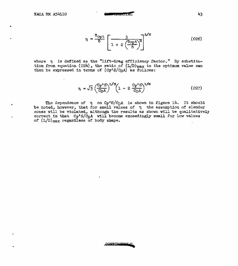
where 9 is defined as the "lift-drag efficiency factor." By substitu- tion from equation (C24), the ratio of (L/D) - to the optimum value can then be expressed in terms of (CF*S/CDA) as follows:
. The dependence of q on C~'S/CDA is shown in figure 14. It should be noted, however, that for small values of q the assumption of slender cones will be violated, although the results as shown will be qualitatively correct in that Cp'S/CDA will become exceedingly small for low values of (L/D) max regardless of body shape.
,
44 NACA RM A54LlO
APPENDIX D
COMPUTA!TION OFEEATIHG ASSOCWED WITHROCKEZ!VEEK!LE%
Radiation of Heat From Glide Vehicles
From equation (72), the maximum time rate of total heat input to the glide vehicle can be expressed as
dQ 0 dt max =
S (Dl)
The rate of heat radiatfon lowing standard relation
from the vehicle can be expressed by the fol-
Using equations (Dl) and (D2), the requirement for continuous radia- tion of all convectfve heat input to a surface at a temperature 2000° R (1540' F) can be expressed as
cF's mg -~1.20 S(L/D) %A
(D3)
If a value of (L/D) 3
= 6 is assumed, values of the parameter C$'S/CDA
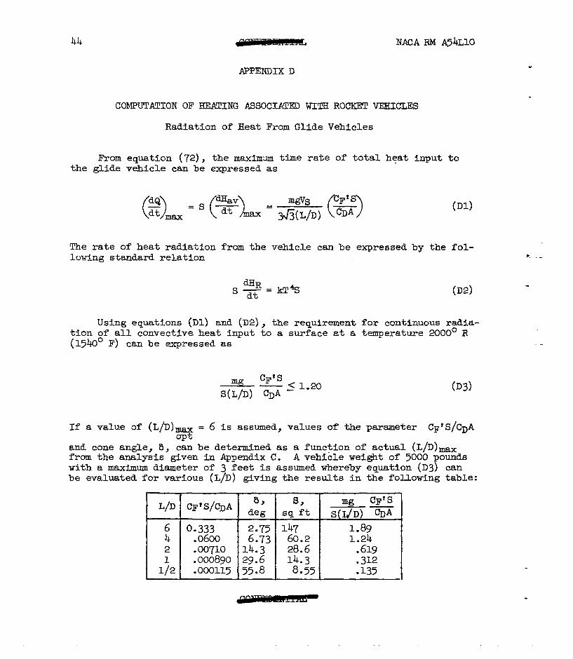
and cone angle, 8, can be determined as a function of actual (L/D)max from the analysis given in Pgpendix C. A vehicle weight of 5000 pounds with a maximum diameter of 3 feet is assumed whereby equation (D3) can be evaluated for various (L/D) giving the results in the following table:
L/D CF'S/CDA 8 de& 1 59 A G 1 S(J+W) WA
6 0.333 2.75 i 147 I 1.89
1 i/21 .oai5 (55.8 1 8.551 .i35 I

NACARM A54L10 45
We see, therefore, that at surface temperatures of 2000° R and for an L/D of 4, this glide-type vehicle can radiate heat at a rate equal to or greater than the maximum convective heat rate.
Radiative and Convective Heat Transfer Associated With Skip Vehicle
In this section the problem is to determine the extent to which heat absorbed by a skip vehicle in the first skipping phase, can be reradiated during the subsequent ballistic phase. The quantfty.of heat absorbed in the first skipping phase has already been obtained fn the heating analysis, (eq. (59) for n = 1)
where the total heat absorbed throughout the entire trajectory is
Ql? 1 CP'S =-- $ lrlVf
2 2 CDA
(D4)
(D5)
In order to determine the heat rtiated, three quantities must be determined:
1. Temperature of the vehicle at the start of the second ballistic phase
2. Temperature of the vehicle at the end of the second ballistic phase
3. The tfme duration of the second ballistic phase
To determine the first of the above quantltfes, we employ the rela- tion for heat absorbed
Ql.= cW&I' (Da
where c is the specific heat of the material, We is the effective weight of material absorbing heat, and LQ is the temperature rise during the first skip. If it is assumed that l/3 of the missile weight wLll
.
46 NACA RM A54LlO
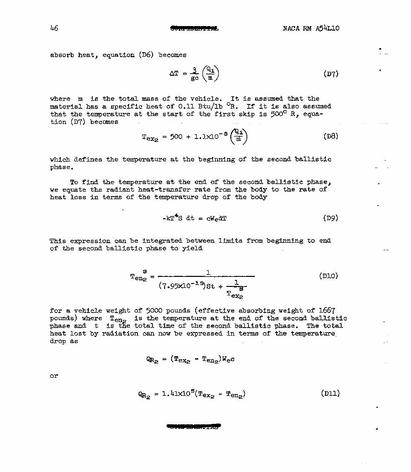
absorb heat, equation (D6) becomes
07)
where m is the total mass of the vehicle. It is assumed that the material has a specific heat of 0.11 Btu/lb OR. If it is also assumed that the temperature at the start. of the first skip is 500' R, equa- tion (D7) becomes
T ex2
= 500 + l.lxlo-s -g (“>
(Da
which defines the temperature at the beginning of the second ballistic phase.
To find the temperature at the end of the second ballistic phase, we equate the radiant heat-transfer rate from the body to the rate of heat loss in terms of the temperature drop of the body
-kT4S dt = cWedT (D9>
This expression can be integrated between limits from beginnfng to end of the second ballistic phase to yield
3 T 1
en2 = @lo) ~7.95xlo-=)st + -+
T ex2
for a vehicle weight of 5000 pounds (effective absorbing weight of 1667 pounds) where Ten is the temperature at the end of the second ballistic phase and t is i&e total time of the second ballistic phase. The total heat lost by radiation can now be expressed in terms of the temperature. drop as
aa = (Tex2 - Ten2)Wec.
or
%2 = l.41X10s(Te, - Tens) (D11)

From reference 7, in combination with the results presented for the motion of a ballistic vehicle (eq. (II)), the time of flight in any bal- listic trajectory can be expressed as
ao(l - cos y2 2 t =-
VS (1 - i2) J3 012)
where
tan Qf i=
Sin2 2 + tan 8fCOS g 2
0 stcl BfCOS 8f -Et=-= l 2
c ) - - co&Q T2
The foregoing relations were applied to a computation of the radia- tfve cooling of a misstie wefghing 5000 pounds and traversing a total range of 3440 nautical miles (Q = 1.0). Values of sf were obtained in the motion analysis, whereas values of CF'S/CDA and S obtained in the previous calculation tith regard to the glide mfssile will apply to this case also. The computations are summarfzed in the following table. Note that the case of 4/D = l/2 is essentially the ballistic vehicle (see fQ3. 9) l
L/D @fr deg
Vf2 &1x10-~ Q&h s;; T
e' TEy Q&x10-
0.135 2l3 1725 .258 335 3x6 t
12.5 o-275 3115 2710 2710 149 0.554 17.0 l 315 1470 1542 1542 1323 .2ll
2 24.0 -575 395 889 889 885 ~27 .04g
1;2 27.5 :E 549 122 -L 0853 247 585 3 30.0 .650 ig -985 80.4 514 0
i
-023 0
We see, therefore, that the quantity of heat which must be absorbed by this skip vehicle decreases rapfdly with decreasing lift-drag ratio. The quantity of heat which must be absorbed by a ballistic vehicle (L/D z l/2) is almost ne
L? igdble compared with the quantities associated
with vehicles with an D = 2 or greater. Comparison of the heat absorbed in the first skipping phase with the heat radiatd in the second ballistfc phase indicates no appreciable advantage is obtained due to radiation for
.
48 NACA RM A54LlO
values of L/D = 2 and lower. To be sure, this situation could be sub- stantially altered (near L/D = 2) by allowing the surface temperatures to reach higher values during the skip; however, it seems most unlikely that the net heat absorbed by the skip vehicle could ever be reduced to the low value of the ballistic vehicle for any reasonable surface tem- perature.

NACARMA54LlO 49
APPENDIXE
DETERMINATION OF THE RATIO OF (L/D),, FOR
A FLAT! PLATE TC (L/D)- FOR A CONE
In Appendix C the expression for the optimum (L/D)- for a slender cone was developed with the assumption of large Mach numbers and a constant value of CF*. A simple analysis will now be presented whereby it is shown that equation (Clg) till apply, for the most part, throughout the Mach number range and for a variable CF'. Inasmuchas theliftcoef- ficient (eq. (Cl)) is essentially independent of Mach number and cone angle, modification of the results obtained in Appendix C (eq. (Clg)) will occur only through the evaluation of the zero-lift drag coefficient (es. (~6) > l
.
The variation wfth Mach number of the zero-lift pressure-drag coef- ficient, (CD,)~, can be represented as
(cDo)p = =(M)sin2S (El)
while CF' is assumed to vary with cone angle in the following manner
where m is chosen to give the required variation of Cp' with 6. By an analysis paralleling that presented in Appendix C, it can be shown that the optimum value of the lift-drag ratio assumes the following form
4 (1 - m/3)
[f(M) I+ (E3)
Now the values of f(M) should not differ greatly from 1 while values of m should not differ greatly from 0. It follows then that values of (L/D) obtained from equation (E3) will not differ appreciably from thosem%tained from equation (Clg). Furthermore, the coefficient CF' will not differ appreciably from CF for the slender shapes and small angles of attack under consideration. Equation (E3) then reduces to the form
.

50 NACA BM A54LlO
0 0
us ,L D ,,-& 4 (E4)
which corresponds to equation (Clg) and is also a suitable approximation for all supersonic Mach numbers.
For a flat plate in supersonic flow, the lift and drag coefficients can be expressed as
CL = J& + 2a2 (E5)
CD = CD0 + &L (EQ
which follows easily from the equation for pressure coefficient given by Ivey and Cline (ref. 16). By noting that
‘Do = 2CF
the lift-drag ratio can be written from equations (E5) and (E6) as
L 2hc& + a2 -= D CF + 2ha2 + a=
cm
where
Equation (ET) is found to have the following maximum value
L 0 1
'rnax=a+ a3 WJ
2(A + a)(2h + a> + (2Z a)
which occurs at values of the independent variables given by the maximum condition 1
- ------ - .
NACA RM A54LlO
CF = a2 2h+ C
From equations (,E4), (E8), and (Eg), and recalling that h = (M2 - l)'1P the ratio of (L/D)- for a flat plate to (L/D)- for a cone can be determined as a function of Mach number and C$. The variation of this ratio with Mach number for given values of C&T has been presented in figure 11, where it was found convenient to use the inverse Mach number the abscissa in order to illustrate conveniently the behavior at hyper- sonic speeds.
as
a2 2(h + a) 1

52 NACA RM A54LlO
1.
2.
3.
4.
5.
6.
7.
8.
9.
10.
11.
12.
1-3.
REFERENCES
Sanger, Eugen: Rakenten-flugtechnik. R. Oldenbourg (Berlin), 1933.
Sanger, Eugen, and Bredt, J.: A Rocket Drive for Long Range Bombers. .._ .__._. -.- - .- .- ._ Tech. Information Branch, Navy Department, Trans. CGD-32, 1944.
Allen, H. Julian, and Eggers, A. J., Jr.:. A Study of the Motion and Aerodynamic Heating of Missiles Entering the Earth's Atmosphere at High Supersonic Speeds. NACA RM A53D28, 1953.
Schamberg, R.: Effects of Flight Speed and Propulsive System on Aircraft Range. The RAND Corporation, R-114, Aug. 13, 1948.
Malina, Frank J., and Summerfield, Martti: The Problem of Escape from the Earth by Rocket. Jour. Aero. Sci., vol. 14, no. 8, Aug. 1947, pp. 471-w.
Timoshenko, S., and Young, D. H.: -Advanced Dynamics. McGraw-Hill, 1948.
King-Hele, D. G., and Gilmore, D. M. C.: Long-Range Surface-to- Surface Rocket Missiles: Properties of Ballistic Trajectories in Vacua. R.A.E. TN No. G. W. 305, Mar; 19%.
Resnikoff, Meyer M.: Optimum Lifting Bodies at High Supersonic Air- speeds. NACA RM A54B15, 1954.
Eggers, A. J., Jr., Dennis, David H., and Resnikoff, Meyer M.: Bodies of Revolution for Minimum Drag at High Supersonic Airspeeds. NACA RM A5lK27, 1952.
Somer, SFmon C., and Stark, James A.: The Effect of Bluntness on the Drag of Spherical Tipped Truncated Cones of Fjlneness Ratio 3 at Mach Numbers 1.2 to 7.4. NACA RM A52313, 1952.
Eggers, A. J., Jr., and Syvertson, Clarence A.: Experimental Inves- tigation of a Body Flare for Obtaining Pitch Stability and a Body Flap for Obtaining Pitch Control in Hypersonic Flight. NACA RM A54J13, 1954.
Sibulkin, Ma: Heat Transfer Near the Forward Stagnation Potit of a Body of Revolution. Jour. Aero. Sci., vol. 19, no. 8, Aug. 1952, PP. 570-571.
Goldstein, S.: Modern Developments in Fluid Mechanics, 1st edition, vol. 2, Oxford Univ. Press, London, 1938, pp. 631-632.

NACA RM A54LlO k 53
14. Prandtl, L.: On Boundary Layers in Three-Dimensional Flow. M.A.P., Volkenrode (Rep. and Trans. No. 64), May 1, 1946.
. 15. Jones, Robert T.: Effects of Sweepback on Boundary Layer and Sepa- ration. NACA Rep. 884, 1947. (Formerly NACA TN 1402)
16. Ivey, H. Reese, and Cline, Charles W.: Effect of Heat-Capacity Lag on the Flow Through Oblique Shock Waves. NACA TN 2196, 1950.
54 NACA RM A54LlO
.

NACA FM A54LlO 55
...............
.X:.$.:.: I 1 1 I I I I ................... .... ..-........p :.:.:.:.:.:.~:.:.:.:*:.:.:...........-...........-...........-~.....................-
............................... ...................................... ....... . ..
.;‘i . ........ .-.-. .................. ........ *.:, ..*.....-....-.-.......-.....-...-.-.- ......................
!i: Escaoe vehctfy i
Y . I I / \I
h
I 1 ~-+A4inhnum vefocity f&e
30 40 50 60 70 8 w I 90-
Figure I.- Vuriafion of velocity with incidence ungle for various vdues of range of buf/istii vehicle.
56 MACA F&l A54L10
Figure 2.- Variofion of effective lift- drug r&i0 with runge for optimum buMstic vehii/e.

NACA RM A54LlO 57
20 40 60 Uisfunce u/ong eurfhh surfucs feef x 10 8o-4TZ-&& ‘0
Figure 3- TYjecfory of fhe firsf sk/pprirp phase for u Sk/;0 vehicle w/ich 0 Mf-drug rufio of 2 and 4 tofu/ runge of 3440 nuuf/‘ca/ miles (@ = //.

.8
6
Figure 4- VanSon of ~Wify witi range tbr wths w&s of lift-dmg ratio for skr;O vehicfe.
.

NACA RM A54LIO
2c
I I
4 6 , Runge pufumefer, 0
figure 5- Vufiufion of effective /iff-dfug futio with range for vufious vdues of uefodynumic Off-dfug fufio of sk/;o vehicle.

I Y 3 6
Figure 6- Varkn’ion of velouiy with row for varhus vohes of tiff-drag r&h of glide vebkle.
I , ‘ *

NACA RM A54LlO
2c
16
/i
6
4
0
61
- 4 6 1
f?unge purumefer, 8
Figure Z- Vuniition of effective tift-drug rufio with runge for vurious vuhes of uerodynumic /iff-drug fufio of glide vehicle.
I.0
.8 c
. .
-/
AJ
-
-
/
, .

, . L
. .
--/-;~-y---------’ _----- L/D-I~/---
/ ,~Lnl’37 ,/
,/ 2yH----
-0’ 4.0,
I I / 2 3
mar mnge, CD4
Figure 9- Var&t,bn of mass ~fh with ttxqe for w&us lift-drtq mtios of hypervabc/ty b&&s

2
__--__----_----.
-------- ------- 4 ---Q&k
t%r - we
vehae --- superm -------- tiphlm
I n A .e I L 0
Fi@? K!- Vwhtion of perhwwnce effkkwcy fuchv WM iota/ rwnge for bafJitiic and g//de keh&s and the sqpmic airphne.
. .
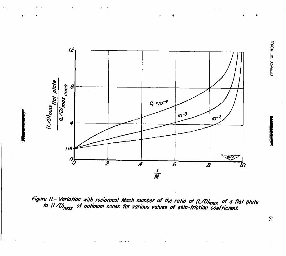
, -I . .
.4 .6 .8 / M

.
L
. .

N ’ , .
2 4 6 8 #?ange parameter 9
Figure AX- Ruttian of range where (L/D) t9 4 0.05 as a function of range for various whes of lift- drag ratio.
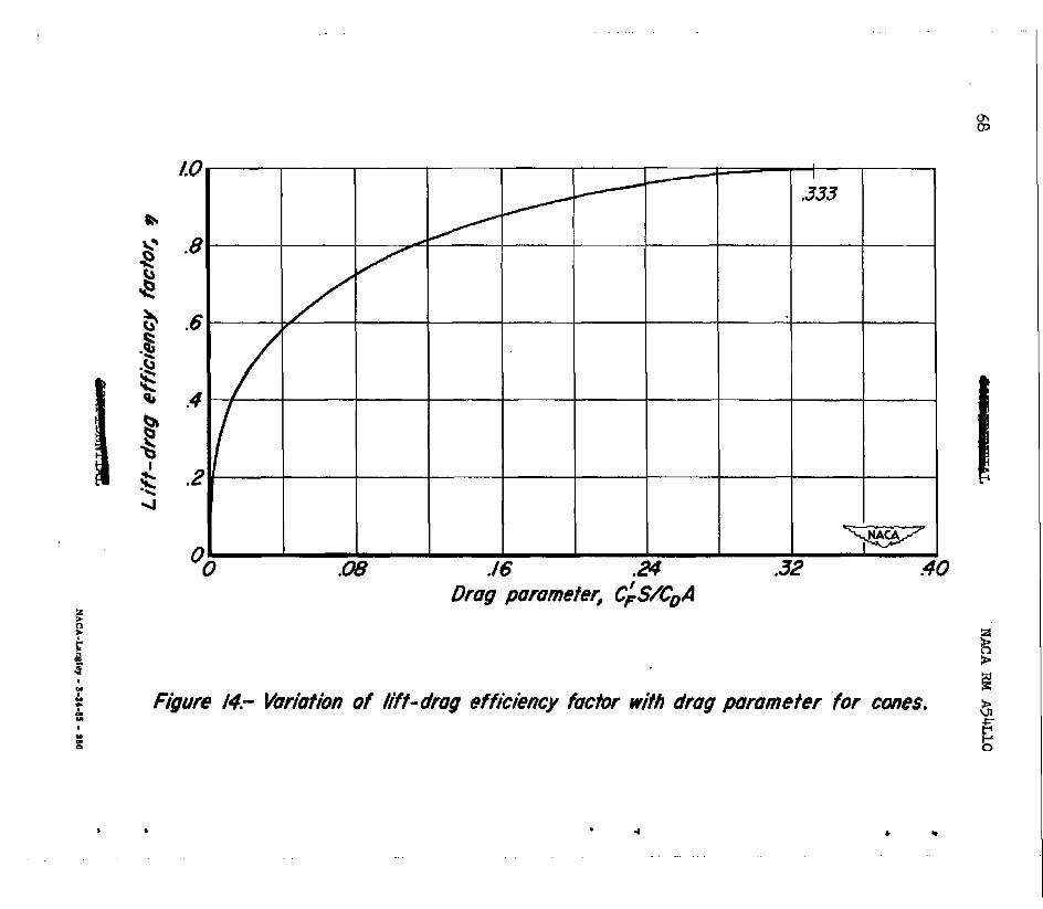
l.0
.8
.6
.4
.a%
G I ,P
I I I
4-F -
/ Q .32
Drug paramefe4 C’S/co A
Figure /4.- Variofion of /i-f&drag efficiency facbr wifh drag parameter for cones.
4G
’ .I l .

0
;