RESEARCH LABORATORY Evaluation of an Outer Loop … · Evaluation of an Outer Loop Retrofit...
34
Evaluation of an Outer Loop Retrofit Architecture for Intelligent Turbofan Engine Thrust Control NASA/TM—2006-214460 October 2006 Jonathan S. Litt U.S. Army Research Laboratory, Glenn Research Center, Cleveland, Ohio T. Shane Sowers Analex Corporation, Brook Park, Ohio ARL–TR–3880 AIAA–2006–5103 U.S. ARMY RESEARCH LABORATORY https://ntrs.nasa.gov/search.jsp?R=20060056247 2018-06-02T19:07:00+00:00Z
Transcript of RESEARCH LABORATORY Evaluation of an Outer Loop … · Evaluation of an Outer Loop Retrofit...

Evaluation of an Outer Loop Retrofit Architecture
for Intelligent Turbofan Engine Thrust Control
NASA/TM—2006-214460
October 2006
Jonathan S. Litt
U.S. Army Research Laboratory, Glenn Research Center, Cleveland, Ohio
T. Shane Sowers
Analex Corporation, Brook Park, Ohio
ARL–TR–3880AIAA–2006–5103U.S. ARMY
RESEARCH LABORATORY
https://ntrs.nasa.gov/search.jsp?R=20060056247 2018-06-02T19:07:00+00:00Z

NASA STI Program . . . in Profile
Since its founding, NASA has been dedicated to the
advancement of aeronautics and space science. The
NASA Scientific and Technical Information (STI)
program plays a key part in helping NASA maintain
this important role.
The NASA STI Program operates under the auspices
of the Agency Chief Information Officer. It collects,
organizes, provides for archiving, and disseminates
NASA’s STI. The NASA STI program provides access
to the NASA Aeronautics and Space Database and its
public interface, the NASA Technical Reports Server,
thus providing one of the largest collections of
aeronautical and space science STI in the world.
Results are published in both non-NASA channels and
by NASA in the NASA STI Report Series, which
includes the following report types:
• TECHNICAL PUBLICATION. Reports of
completed research or a major significant phase
of research that present the results of NASA
programs and include extensive data or theoretical
analysis. Includes compilations of significant
scientific and technical data and information
deemed to be of continuing reference value.
NASA counterpart of peer-reviewed formal
professional papers but has less stringent
limitations on manuscript length and extent of
graphic presentations.
• TECHNICAL MEMORANDUM. Scientific
and technical findings that are preliminary or
of specialized interest, e.g., quick release
reports, working papers, and bibliographies that
contain minimal annotation. Does not contain
extensive analysis.
• CONTRACTOR REPORT. Scientific and
technical findings by NASA-sponsored
contractors and grantees.
• CONFERENCE PUBLICATION. Collected
papers from scientific and technical
conferences, symposia, seminars, or other
meetings sponsored or cosponsored by NASA.
• SPECIAL PUBLICATION. Scientific,
technical, or historical information from
NASA programs, projects, and missions, often
concerned with subjects having substantial
public interest.
• TECHNICAL TRANSLATION. English-
language translations of foreign scientific and
technical material pertinent to NASA’s mission.
Specialized services also include creating custom
thesauri, building customized databases, organizing
and publishing research results.
For more information about the NASA STI
program, see the following:
• Access the NASA STI program home page at
http://www.sti.nasa.gov
• E-mail your question via the Internet to
• Fax your question to the NASA STI Help Desk
at 301–621–0134
• Telephone the NASA STI Help Desk at
301–621–0390
• Write to:
NASA STI Help Desk
NASA Center for AeroSpace Information
7121 Standard Drive
Hanover, MD 21076–1320

National Aeronautics and
Space Administration
Glenn Research Center
Cleveland, Ohio 44135
U.S. ARMY
RESEARCH LABORATORY
Prepared for the
42nd Joint Propulsion Conference and Exhibit
cosponsored by the AIAA, ASME, SAE, and ASEE
Sacramento, California, July 9–12, 2006
Evaluation of an Outer Loop Retrofit Architecture
for Intelligent Turbofan Engine Thrust Control
NASA/TM—2006-214460
October 2006
Jonathan S. Litt
U.S. Army Research Laboratory, Glenn Research Center, Cleveland, Ohio
T. Shane Sowers
Analex Corporation, Brook Park, Ohio
ARL–TR–3880AIAA–2006–5103

Acknowledgments
The authors gratefully acknowledge Sanjay Garg’s significant role in the development of the overall retrofit architecture,
Tak Kobayashi’s contribution of the FADEC-like controller and piecewise linear model, and his invaluable assistance,
and Don Simon’s substantiating investigations into the use of common SVD-based tuners across the flight envelope.
This research was supported by Propulsion 21.
Available from
NASA Center for Aerospace Information
7121 Standard Drive
Hanover, MD 21076–1320
National Technical Information Service
5285 Port Royal Road
Springfield, VA 22161
Available electronically at http://gltrs.grc.nasa.gov
Level of Review: This material has been technically reviewed by technical management.

Evaluation of an Outer Loop Retrofit Architecture for
Intelligent Turbofan Engine Thrust Control
The thrust control capability of a retrofit architecture for intelligent turbofan engine
control and diagnostics is evaluated. The focus of the study is on the portion of the
hierarchical architecture that performs thrust estimation and outer loop thrust control. The
inner loop controls fan speed so the outer loop automatically adjusts the engine’s fan speed
command to maintain thrust at the desired level, based on pilot input, even as the engine
deteriorates with use. The thrust estimation accuracy is assessed under nominal and
deteriorated conditions at multiple operating points, and the closed loop thrust control
performance is studied, all in a complex real-time nonlinear turbofan engine simulation test
bed. The estimation capability, thrust response, and robustness to uncertainty in the form of
engine degradation are evaluated.
Nomenclature
CLM = Component Level Model
EGT = Exhaust Gas Temperature
FADEC = Full Authority Digital Engine Control
FN = Net Thrust
HM = Health Management
HPC = High Pressure Compressor
HPT = High Pressure Turbine
IWP = Integrator Windup Protection
LPC = Low Pressure Compressor
LPT = Low Pressure Turbine
OLC = Outer Loop Control
PI = Proportional-Integral
PLA = Power Lever Angle
SVD = Singular Value Decomposition
T49 = LPT Inlet Temperature, used for EGT
WF36 = Fuel Flow
XNR2 = Percent Corrected Fan Speed
I. Introduction
ariations in turbofan engine performance can be attributed to several factors including manufacturing
tolerances and deterioration caused by use. These variations manifest themselves as shifts in engine variables,
which with use will eventually drive the engine to the limit of operability. Thus the control system must be robust
V
Jonathan S. Litt U.S. Army Research Laboratory
Glenn Research Center Cleveland, Ohio 44135
T. Shane Sowers
Analex Corporation Brook Park, Ohio 44142
NASA/TM—2006-214460 1

Figure 1. Cross section of a high-bypass commercial-type turbofan engine.
enough to keep the engine operating within acceptable boundaries for several thousand flight cycles. In a typical
turbofan control system, the pilot’s throttle command is used to set fan speed, which is assumed to be highly
correlated to engine thrust, the unmeasured variable of interest. However, as the engine ages, the relationship
between fan speed and thrust changes, so in a degraded engine the thrust level is often different from that produced
by a new engine for the same throttle setting. In a multi-engine aircraft, this can cause a thrust imbalance and
unwanted yawing. If thrust were directly controlled, this situation could be avoided. It is possible to achieve this
result using fan speed control by adjusting the fan speed reference signal to accommodate the degraded throttle-to-
thrust relationship.
The adjustment of fan speed command implies the use of an outer loop control. Knowing how much to adjust it,
and more importantly why it needs to be adjusted, implies intelligence. An Intelligent Propulsion Control
architecture is one that increases the level of autonomy of the engine. In this context it means that it should at least
be able to recognize performance deterioration, diagnose faults, and alter its power setting to recover whatever lost
thrust is possible within the physical constraints of the system, even with degraded capability.1 Thus an instantiation
of such an architecture should be populated with at least some basic diagnostic/health management functions along
with some model-based reasoning ability about the engines’ degraded performance and operability. A conceptual
architecture of this type was developed and the outer loop thrust control was demonstrated to reduce pilot workload
in cases where the engines suffered from unequal levels of deterioration, by automatically balancing thrust.2 The
current paper focuses on the interaction between the outer loop control portion of the architecture and a single
engine, in order to evaluate the effectiveness of the approach in the presence of uncertainty of the forms typically
encountered: model mismatch, nonlinearities, noise, etc.
The remaining portions of this section give an overview of pertinent aspects of the turbine engine industry’s
method of engine control as well as an approach that enables the implementation of an Intelligent Propulsion
Control architecture, given the current practice. This is followed by a description of the proposed architecture in
general, then details of the current implementation, specifically the thrust estimator and outer loop control. Results
of an evaluation of the outer loop control to various degradation scenarios are presented next. Finally, conclusions
are drawn about the robustness of the implementation.
NASA/TM—2006-214460 2

A. Turbofan Engine Operation and Degradation
A commercial turbofan engine gas path consists of both rotating and non-rotating components arranged from
inlet to exhaust (Figure 1). The first rotating component of a turbofan engine is the fan, which is behind the engine
inlet, and in a commercial engine it provides most of the thrust by accelerating a vast quantity of air in the front of
the engine and exhausting it directly out the back, bypassing the other components. A small percent of the air passes
through the remaining rotating components of the engine. The first of these remaining components is the low
pressure compressor (LPC), which is followed by the high pressure compressor (HPC). This opens into the
combustor where fuel is injected and burned. The resulting hot gas drives the high pressure turbine (HPT) and the
low pressure turbine (LPT), which power the fan and compressors. Each of these components affects the engine’s
performance, and the performance degradation is embodied in component health. The state of each component’s
health involves characteristics that degrade over time: such features as efficiency, flow capacity, and seal leakage.
These tend to change slowly over many flights, but may change abruptly with the occurrence of a sudden fault. A
change of as little as several percent to efficiency and flow capacity may represent the full permissible degradation
range of the component.
B. Propulsion Control The development of control laws for a turbine engine is an involved process. Typical aircraft engine control
systems maintain fan speed or engine pressure ratio to regulate thrust, which is not directly measurable. The
controllers are generally based on a variant of a Proportional-Integral (PI) scheme, combined with limit logic (Figure
2). This limit logic consists of a series of min select and max select blocks, each of which selects a fuel flow rate
command based on various physical limits, acceleration/deceleration schedules (reference signal for rotor speed
rate-of-change vs. rotor speed), and the current operating state (speed governor loops). The final command that exits
the selection logic block is integrated to produce a new total fuel flow.3 Thus an increment of zero will result in no
change in fuel flow, and a constant steady fuel flow will occur when steady state error is eliminated. Other actuators,
such as bleed valves and guide vanes, are scheduled open loop, which means that they receive a pre-determined
command based on sensed parameters.
The limit logic is quite complex to develop and validate, and extensive simulation testing is required before it is
ready to be implemented. The logic might be developed in a block diagram language format that can be compiled
into executable code that runs on a flight-certified Full Authority Digital Engine Control (FADEC). The FADEC
software implementation must go through a rigorous verification and validation process to meet stringent
certification requirements.4 The time and cost involved in developing and certifying an engine controller make it
prohibitive to perform any modification to existing FADEC code.
C. Retrofit Architectures A retrofit control architecture is one that can be added on top of an existing structure without significant
modification. It should alter the signals into or out of the existing controller, but the controller itself should remain
intact. For a complex system that requires certification, it might be easier to add externally than to start from scratch,
so that, if anything, only the new portion needs additional certification. Reference 2 discusses an architecture of this
form that adjusts the command going into the controller of a degraded engine in order to provide the equivalent
Rotor Speed
Governing
Loops
Accel/Decel
Loops
Limiting
Loops
Selection LogicSelection LogicSelection Logic
Integrator
Fuel
Metering
Valve
Min
Select
Max
Select
Min
Select
Max
Select
Rotor Speed
Governing
Loops
Accel/Decel
Loops
Limiting
Loops
Selection LogicSelection LogicSelection Logic
Integrator
Fuel
Metering
Valve
Min
Select
Max
Select
Min
Select
Max
Select
Figure 2. Typical turbine engine control logic.
NASA/TM—2006-214460 3

thrust of a new engine. The development of an Intelligent Control structure for the propulsion system of an airplane
can reduce pilot workload, improve diagnostic capability and fault-tolerant operation, and can thus benefit safety
and operability, but because of the complexity of the FADEC, it is an excellent candidate to be implemented as a
retrofit.
II. Overview of Intelligent Retrofit Architecture
The proposed retrofit architecture, introduced in Reference 2, is shown in Figure 3. The purpose of the
architecture is to automatically maintain balanced thrust as the engines deteriorate with use. The system works by
adjusting the fan speed setpoint of each engine individually so that its net thrust is the same as for a new engine for
the demanded Power Level Angle (PLA, the pilot’s throttle input), within the physical constraints of the system. The
architecture is hierarchical with the lowest level performing standard engine control, the next level up maintains
balanced thrust with an outer loop thrust control, and the top level consists of the health management and intelligent
thrust demand logic. This whole structure is below the flight/mission level. The role of the mission level controller
(or intelligent flight controller) is to carry out a mission determined by the capabilities of the overall system (engines
and airframe) and modify it based on new information about the situation and the health of the system. For instance,
if the engine is unable to meet the demand in a safe way, this information would be reported to the intelligent flight
controller or mission manager and the set point is adjusted by logic to maintain balanced thrust at a safe level. The
mission manager will not be considered here. Figure 3 shows the overall architecture in block diagram form. The
blocks in yellow represent the engines under standard closed loop fan speed control. Above each of the yellow
blocks hierarchically is a thrust estimator which generates an estimate of the thrust the engine is producing for use
Thrust
Setpoint
Logic
Engine
ControlEngine 1
PI
Control
with IWP
Thrust
Estimator
Engine
ControlEngine 2
PI
Control
with IWP
Thrust
Estimator
Nominal
Engine
Model
+
+
+
+
+-
+-
PLA
PLA
∆PLA Thrust Error
∆PLA Thrust Error
ThrustDemand
ExpectedThrust, etc.
PLA to Thrust Mapping
To/From Mission Manager
EngineHM
Outer Loop Control Level
Inner Loop Control Level
Intelligent Control
Level
Outer Loop Control Level
Inner Loop Control Level
Thrust
Setpoint
Logic
Engine
ControlEngine 1
PI
Control
with IWP
Thrust
Estimator
Engine
ControlEngine 2
PI
Control
with IWP
Thrust
Estimator
Nominal
Engine
Model
+
+
+
+
+-
+-
PLA
PLA
∆PLA Thrust Error
∆PLA Thrust Error
ThrustDemand
ExpectedThrust, etc.
PLA to Thrust Mapping
To/From Mission Manager
EngineHM
Outer Loop Control Level
Inner Loop Control Level
Intelligent Control
Level
Outer Loop Control Level
Inner Loop Control Level
Figure 3. Intelligent retrofit architecture. The hierarchical structure consists of the Inner Loop Control (in
the yellow boxes), the Outer Loop Control (in the green boxes), and the Intelligent Control (in the salmon
box).
NASA/TM—2006-214460 4

with the outer loop thrust control (green boxes). The blocks along the top in the salmon box represent the structure
of an intelligent control framework. They consist of the throttle to output (thrust, etc.) mapping, the Health
Management (HM) block, and the thrust setpoint logic for the outer loop control. The HM block determines the
fitness of the engine to carry out the expected mission, and finds a way to achieve it if possible, through the thrust
setpoint logic. Otherwise it coordinates with the Mission Manager to modify the requirements on the engine to an
acceptable level.
A. Inner Loop Control
The Inner Loop Control Level (yellow box in Figure 3) contains the standard engine controller. It is usually a
FADEC which is designed to maintain fan speed for performance while not exceeding operability limits. It consists
of an incremental PI controller for steady state fan speed control, as well as acceleration and deceleration schedules
and other limit logic. The pilot’s input to the controller is PLA, which is mapped to a corrected fan speed command;
the engine is controlled to this value.
B. Outer Loop Control
The Outer Loop Control (green box in Figure 3) adjusts the reference signal for the Inner Loop Control. In
general, the PLA or throttle, which is a pilot input, sets the fan speed command that is calibrated to achieve a desired
thrust. However, with engine degradation or some other change in the throttle-to-thrust relationship, the PLA setting
will not produce the desired thrust. In order to bring the thrust to the correct level, the fan speed command is
adjusted by the outer loop controller. The FADEC logic is designed to prevent the engine from operating in an
unsafe mode, so the incremental PLA value (the adjustment due to the outer loop control, so that the resulting fan
speed command results in the desired thrust level), which enters the FADEC along with the pilot input PLA, will not
drive the engine into an inappropriate operational regime. The change in fan speed command is obtained by driving
the error in thrust to zero. Since thrust is not measurable in flight, it must be estimated. The thrust estimator
implemented here uses a Kalman filter with an optimal reduced order model of the effect of engine degradation.5
The inputs to the Kalman filter are corrected fuel flow, the open loop scheduled actuators (Variable Bleed Valve and
Variable Stator Vanes) and the seven corrected sensed engine variables. The use of corrected variables as inputs to
the linear estimator extends its range because the correction factors have the effect of transforming the engine
operating condition to a standard operating point,6 usually sea level, standard day. This allows meaningful
comparison of engine data at different conditions and different levels of degradation.7 In a practical sense, it enables
the Kalman filter to accurately estimate the thrust of a degraded engine at an operating point far from the point
where the optimal linear estimator was designed. The difference between the estimated and desired thrust is fed
through a PI controller which adjusts the fan speed command by manipulating PLA until the thrust error is zero. The
Outer Loop Control level contains integrator windup protection (IWP) on the PI controller. The outer loop controller
is tuned to avoid introducing unwanted dynamics. It is important that the inner and outer loop controllers are
operating on different time scales to avoid interaction; since the inner loop provides direct control while the outer
loop adjusts the reference signal, the outer loop should respond more slowly.
C. Intelligent Control
The Intelligent Control Level (salmon box in Figure 3) contains the parts of the control structure that evaluate
the safety, performance, and capabilities of the engines. Unlike the lower levels for which each engine had a copy,
there is only a single copy of this level; it monitors the propulsion system of the aircraft. It takes input from both
engines (control signals, sensed variables, thrust estimate, etc.) to determine each engine’s current health and fitness
for the mission. It also generates the outer loop thrust command that both engines follow. Ideally, activity at the
Intelligent Control Level will be limited to assessment and consent, but as the engines age and degrade, or when an
anomaly occurs, the health management algorithms determine the appropriate action, which generally has to do with
the fan speed setting. If the Intelligent Control determines that the condition of an engine is such that corrective
action is beyond the scope of the propulsion control (for instance, a problem that might compromise the mission) it
communicates this information to the Mission Manager. What the Intelligent Control does not do is adapt the inner
loop control; since this is a retrofit architecture it is specifically designed to adjust the signal going into the FADEC,
not the FADEC itself.
III. Test Setup
The focus of this paper is the thorough evaluation of the thrust control portion of the architecture implemented
with a single engine across a wide operating range. Thus the emphasis is on thrust estimation capability and closed
NASA/TM—2006-214460 5

Table 2. Sensor Sets and Sensor Standard Deviation (Std. Dev. as % of Steady-State Values at Full Power)
Sensor Set (Figure 1) Standard Deviation (%)
XN12 (rotational speed) 0.25
XN25 (rotational speed) 0.25
P17 (pressure) 0.50
T25 (temperature) 0.75
PS3 (pressure) 0.50
T3 (temperature) 0.75
T49 (temperature) 0.75
Table 1. State Variables, Health Parameters, Actuators, and Auxiliary Output
State Variables Health Parameters Actuators Auxiliary Output
Fan Speed, XN12 FAN efficiency Fuel Flow, WF36 Thrust, FN
Core Speed, XN25 FAN flow capacity Variable Bleed Valve, VBV
metal temperature 1 LPC efficiency Variable Stator Vanes, VSV
metal temperature 2 LPC flow capacity
metal temperature 3 HPC efficiency
metal temperature 4 HPC flow capacity
metal temperature 5 HPT efficiency
metal temperature 6 HPT flow capacity
metal temperature 7 LPT efficiency
LPT flow capacity
loop command tracking. The airframe and related issues such as thrust asymmetry with multiple engines, and pilot
workload reduction have already been reported.2 Functions of the Intelligent Control level beyond the nominal
engine model and corresponding thrust setpoint logic will not be evaluated, i.e., diagnostic algorithms per se will not
be evaluated.
A. Real-time hardware-in-the-loop implementation and testing
The closed loop system was set up on two asynchronous computers, one executing the simulation of the large
commercial turbofan engine in real time, the other executing the outer loop thrust control portion of the hierarchical
controller including the FADEC-like engine control.
B. Large Commercial Turbofan Engine Simulation The engine is represented by a nonlinear Component Level Model (CLM) simulation. The model has nine state
variables, 10 health parameters, three control inputs, and one auxiliary (unmeasured) output all shown in Table 1, as
well as seven sensors shown in Table 2 (see Figure 1 for sensor locations). It must be noted that for this work, the
more common P25 measurement is replaced by P17; without this substitution, thrust estimation is poor.5 This
indicates that the ability to estimate unmeasured outputs is strongly influenced by sensor selection. The Exhaust
Gas Temperature (EGT) is represented by T49.
C. Piecewise linear model
A piecewise linear model is composed of a set of linear models derived at multiple operating conditions.
Through interpolation of the linear models, the piecewise linear model is able to represent the original nonlinear
system over a wide operating range.8 A piecewise linear model is used as the basis for both the nominal model
which provides the outer loop thrust reference command, and the Kalman filter that performs the thrust estimation.
The piecewise linear model is developed by linearizing the CLM at multiple altitude-Mach number-PLA triples,
with PLA varying across its range for each altitude-Mach number pair shown in Figure 4; these altitude-Mach
number pairs are selected to be along a typical takeoff/climb/cruise trajectory of a commercial turbofan engine. Each
linear model consists of the linear dynamics in state space form and trim values for all variables. In the piecewise
linear model structure, the trim values and the state space matrices are linearly interpolated using percent corrected
fan speed and environmental condition (a function of ambient pressure and engine inlet pressure, which are related
to altitude and Mach number) as the scheduling parameters. While all trim points are used, it was found that
interpolating the dynamics from just the sea level static and cruise points (altitude-Mach number-PLA triples)
provide sufficient fidelity to match the CLM in the neighborhood of the linearization points in most cases, and
NASA/TM—2006-214460 6

Flight Envelope
0
5000
10000
15000
20000
25000
30000
35000
40000
45000
0 0.2 0.4 0.6 0.8 1
Mach Number
Alt
itu
de (
ft)
Flight Envelope
0
5000
10000
15000
20000
25000
30000
35000
40000
45000
0 0.2 0.4 0.6 0.8 1
Mach Number
Alt
itu
de (
ft)
Figure 4. Flight envelope of the engine showing points along the takeoff/climb/cruise trajectory.
adding more sets does not significantly improve the results. The piecewise linear model that represents the nominal
engine does not account for degradation, either in the trim values or the dynamics. In the final implementation of the
nominal model which provides the thrust reference, just the interpolated trim points were used; the dynamics are
unnecessary due to the outer loop’s relatively slow time scale.
D. Thrust Estimation
The Kalman filter used for thrust estimation is based on the piecewise linear model but it does account for
degradation through the incorporation of additional sensitivity matrices relating the health parameters to the other
variables. The special procedure to modify the linear models used to obtain the Kalman gains is described below.
The Kalman filter equations are interpolated the same way as those of the piecewise linear model.
The problem of thrust estimation using a Kalman filter has been addressed5 and demonstrated in a flight
simulator in the neighborhood of a single operating point.2 The difficulty in implementing a direct thrust control
system arises because thrust is not directly measurable and the relationship between fan speed and thrust changes
with engine deterioration. If engine deterioration could be estimated, thrust could be reconstructed fairly accurately,
but the limited number of sensors on a typical commercial engine makes the deterioration estimation problem
underdetermined. The optimal linear approach of Ref. 5 utilizes singular value decomposition (SVD) to reduce the
number of parameters to be estimated. This can be seen by examining the linearized engine model, which has the
form
x Ax Bu Lp w
y Cx Du Mp v
z Ex Fu Np
= + + +
= + + +
= + +
&
(1)
where the health parameter vector, p, appears as input to the system, the auxiliary parameter vector z represents
thrust, L, M, and N are sensitivity matrices of the appropriate dimension, w and v represent noise. For estimation, eq.
(1) can be rearranged as
NASA/TM—2006-214460 7

[ ]
[ ]
0 0 0
x A L x Bu w
p p
xy C M Du v
p
xz E N Fu
p
= + +
= + +
= +
&
&
(2)
where the health parameters, which are assumed to vary slowly, appear as state variables and are thus able to be
estimated by a Kalman filter as long as the system is observable; unfortunately, typically engines have too few
sensors to allow all heath parameters to be estimated. Reference 5 demonstrated that by using SVD to reduce the
number of parameters to be estimated, unmeasurable parameters such as thrust may be estimated in an optimal
fashion. This is achieved by approximating L, M, and N from eq. (1) by the reduced rank matrix product [LT M
T
NT]
T≈U
*V
*, and an observable vector q≈V
*p. Thus the approximations to L, M, and N all have a common right factor,
making them amenable to the reconstruction of unmeasurable outputs. Thus
( )
*
* * * *
*
L
T T
k k k M
N
L U
M U V U V U V U V
N U
= Σ ≈ Σ = =
where U*=UkΣk and V
*=Vk
T correspond to the k largest singular values of [L
T M
T N
T]
T. Thus eq. (2) can be
approximated as *
*
*
00 0
L
M
N
x x BA Uu w
q q
xy C U Du v
q
xz E U Fu
q
= + +
= + +
= +
&
&
where q replaces p as the vector of tuners that is of low enough dimension to be estimated.
This method can be extended to piecewise linear models by stacking the sensitivity matrices that relate the
degradation to shifts in the state, sensed, and auxiliary variables from all linearization points to obtain a single right
factor and thus a common q vector across the flight envelope as
1 1
1 1
1 1
*1
*1
*
1
*
*
*
*
n n
n n
n n
L L
M M
N N
T
L Ln
M Mn
N Nn
L U U
M U U
N U U
V V
U UL
U UM
U UN
= Σ ≈
M MM (3)
The SVD approach to model order reduction defines the optimal set of tuners in a least squares sense. In this
case, 10 health parameters are replaced by seven tuners, thus introducing additional, albeit known modeling error.5
The optimality of the approach lies in the fact that the least information possible is lost during the order reduction,
and the SVD methodology achieves this by retaining the seven largest of the 10 singular values. Table 3 lists the
singular values from this implementation, and it can be seen that while the dropped singular values are not
insignificant, they are still relatively small compared to those that are retained.
NASA/TM—2006-214460 8

Table 3. Singular Values of the Health Parameter Sensitivity Matrices (shaded singular values are dropped)
σ1 σ2 σ3 σ4 σ5 σ6 σ7 σ8 σ9 σ10
28.111 20.299 15.936 12.071 9.9994 7.2892 5.0358 3.782 2.1 1.6902
E. Proportional-Integral Control with Integrator Windup Protection
A PI controller is used in the outer loop to adjust the PLA value entering the FADEC such that desired thrust is
achieved. The PI controller implemented here has fixed gains and is tuned to give an acceptable response for the
takeoff/climb/cruise trajectory used for testing. In an implementation designed to cover more of the flight envelope,
a gain-scheduled PI controller might need to be designed. Integrator Windup Protection is necessary for the outer
control loop because it delivers a ∆PLA command to the inner loop control, which could potentially result in a gross
value above the maximum PLA limit, especially in cases where a degraded engine’s thrust is significantly lower
than nominal for a given PLA. Since this would result in a saturating command, the integral term would tend to
wind up, resulting in an oscillatory response. The protection scheme implemented here is the simple conditional
integration or integrator clamping where the integration is stopped and the value fixed once the limit is reached, and
integration is only restarted when the appropriate condition (total PLA entering the FADEC≤maximum) is fulfilled.9
IV. Evaluation Results
The engine is represented by a full envelope, nonlinear, high fidelity simulation, and the controller consists of
the Inner Loop and Outer Loop levels as well as the Nominal Engine Model from the hierarchical intelligent control
architecture shown in Figure 3, with the inner-loop engine control maintaining fan speed. Many scenarios are run to
evaluate the system’s performance in real time, using a wide range of component degradation values. The scenarios
are limited to cases where fan speed adjustment is all that is required.
A. Evaluation approach
The evaluation approach utilizes a nonlinear simulation with 10 adjustable health parameters, and a piecewise
linear Kalman filter to estimate thrust up to the degradation limit of the engine. The evaluation is performed in two
stages. First, steady state testing is performed, initially of the thrust estimate, and then of outer loop thrust control at
multiple operating points and degradation conditions. If the thrust estimator is able to reconstruct the true thrust
accurately, then it stands to reason that the thrust can be controlled to match that of the nominal engine as long as it
is within the physical limits of the engine to do so. Second, transient testing is performed under outer loop control,
where engines of various health conditions are run through a takeoff/climb/cruise trajectory to confirm that nominal
thrust response can be attained by a degraded engine.
B. Steady State Evaluation
The purpose of the steady state evaluation is to determine the accuracy of the thrust estimation and control at
several linearization points. Variations in the level of degradation of the nonlinear engine simulation are used with
and without sensor noise to test the performance of the closed loop system. Results are reported for thrust estimation
at multiple levels of engine degradation and PLA values, and for outer loop thrust control at values of PLA away
from the maximum PLA saturation limit.
First the simplest scenario is checked. The thrust estimation accuracy is evaluated at each of the 10 steady state
operating points (Figure 4) for multiple PLA values. The normalized results of evaluating 50 random levels of
deterioration ranging from 1-5% in each health parameter without sensor noise appear in Table 4. Normalization is
performed by dividing the data gathered at each operating point by the nominal thrust level at that operating point. It
can be seen that the error is generally small, indicating good accuracy over the operating range. The estimation error
and its standard deviation tend to be larger at the operating points in the middle and smaller at the ends, which is to
be expected because, as previously mentioned, only the state space matrices from the two end points are interpolated
in the piecewise linear model. An unexpected result, which can be seen by comparing the magnitudes of the mean of
the error and the mean of the absolute error, is that they are the same in most cases, indicating that there is a
directional bias in the estimation error; this is probably due to the modeling error introduced by the reduced order
approximation using SVD.
NASA/TM—2006-214460 9

1 2 3 4 5 6 7 8 9 100.94
0.96
0.98
1
1.02
1.04
1.06
1.08
Operating Point
Nor
mal
ized
Thr
ust a
nd T
hrus
t Est
imat
e
Normalized Thrust and Thrust Estimate, PLA=60
1 2 3 4 5 6 7 8 9 10
0.85
0.9
0.95
1
1.05
1.1
Operating Point
Nor
mal
ized
Thr
ust a
nd T
hrus
t Est
imat
e
Normalized Thrust and Thrust Estimate, PLA=70
1 2 3 4 5 6 7 8 9 100.85
0.9
0.95
1
1.05
1.1
Operating Point
Nor
mal
ized
Thr
ust a
nd T
hrus
t Est
imat
e
Normalized Thrust and Thrust Estimate, PLA=80
1 2 3 4 5 6 7 8 9 10
0.85
0.9
0.95
1
1.05
1.1
Operating Point
Nor
mal
ized
Thr
ust a
nd T
hrus
t Est
imat
e
Normalized Thrust and Thrust Estimate, PLA=84
Figure 5. True thrust (××××) and thrust estimate (O) for nominal engine and worst case degradation
scenarios, nominal in green, cold section (fan, LPC, HPC) degradation in blue, hot section (HPT, LPT)
degradation in red, at four constant PLA levels, no sensor noise.
Table 4. Percent Normalized Mean Error, Standard Deviation, and Mean Absolute Error of thrust
estimation at multiple operating points (Figure 4), no noise, 50 random levels of deterioration ranging from
1-5% in each health parameter.
PLA
↓
Operating
Point → 1 2 3 4 5 6 7 8 9 10
Mean(%error) -0.01 1.53 1.55 1.66 1.28 0.94 0.55 0.11 -0.20 -0.30
StdDev(%error) 0.06 0.33 0.43 0.51 0.49 0.35 0.24 0.16 0.12 0.09 84
Mean(abs(%error)) 0.05 1.53 1.55 1.66 1.28 0.94 0.56 0.17 0.20 0.30
Mean(%error) 0.13 0.74 0.67 0.90 0.95 0.67 0.37 -0.03 -0.25 -0.31
StdDev(%error) 0.05 0.25 0.28 0.30 0.28 0.18 0.16 0.12 0.11 0.10 70
Mean(abs(%error)) 0.13 0.74 0.67 0.90 0.95 0.67 0.37 0.09 0.25 0.31
Mean(%error) -0.05 0.63 0.51 0.56 0.52 0.53 0.09 -0.23 -0.44 -0.44
StdDev(%error) 0.04 0.20 0.20 0.21 0.21 0.21 0.14 0.09 0.08 0.11 60
Mean(abs(%error)) 0.05 0.63 0.51 0.56 0.52 0.53 0.13 0.23 0.44 0.44
Figure 5 shows the normalized thrust and thrust estimate for the nominal engine as well as for the worst case
degradation scenarios at the steady state flight conditions (Figure 4) with various PLA settings, the sensor outputs
are not corrupted by noise. In this context, worst case is defined as the largest degradation-induced shift in either
direction—5% reduction in efficiency and flow capacity of each component in the cold section of engine (fan, LPC,
HPC) in one case, and 5% shift in efficiency (reduction) and flow capacity (increase) of each component in the hot
NASA/TM—2006-214460 10

1 2 3 4 5 6 7 8 9 100.85
0.9
0.95
1
1.05
1.1
Operating Point
Nor
mal
ized
Thr
ust a
nd T
hrus
t Est
imat
eNormalized Thrust and Thrust Estimate, PLA=70
Thrust, hot section degradation, OLC onThrust Estimate, hot section degradation, OLC onThrust, cold section degradation, OLC onThrust Estimate, cold section degradation, OLC onThrust, hot section degradation, OLC offThrust Estimate, hot section degradation, OLC offThrust, cold section degradation, OLC offThrust Estimate, cold section degradation, OLC off
Figure 6. Steady state thrust for worst case degradation at each operating point (Figure 4), with and
without outer loop control, PLA=70, sensor noise included, results based on averaging 1000 samples per
operating point.
section of engine (HPT, LPT) in the other.2 Again, normalization is performed by dividing the data gathered at each
operating point by the nominal thrust level at that operating point. Figure 5 demonstrates the relative size of the
estimation error to the magnitude of the degradation-induced shift. The error for the cold section degradation case
tends to be larger than for the hot section degradation case, which is probably a result of the SVD-based model
reduction; this can be fine-tuned if desired.5 Since the estimation error is generally small relative to the degradation-
induced shift, it suggests that the thrust estimate might be used effectively for outer loop thrust control.
Finally, the steady state scenario is repeated with sensor noise added and outer loop thrust control active. A
constant PLA value of 70 is used, not near enough to the PLA limit to cause saturation at most test points. Figure 6
shows how thrust is maintained at the correct value at each operating point with worst case hot section degradation.
It is clear that for the cold section degradation case, the ∆PLA increment saturates the PLA input at the higher
operating points and thrust matching is not possible. Even with outer loop control active, the thrust level approaches
the value obtained with no outer loop control.
C. Transient Evaluation
The transient evaluation involves comparing simulated engine responses with varying levels of degradation with
and without outer loop thrust control. The objective is to determine whether the outer loop control is able to
maintain the nominal thrust response over a typical flight trajectory. The transient used is a realistic take-
off/climb/cruise trajectory as shown in Figure 7. The trajectory passes though or near each of the 10 linearization
points shown in Figure 4, as can be seen in Figure 8, which shows the actual path superimposed on the surface of
linearization points.
NASA/TM—2006-214460 11

0 200 400 600 800 1000 1200 1400 1600 1800 20000
1
2
3
4x 10
4
Alti
tude
0 200 400 600 800 1000 1200 1400 1600 1800 20000
0.25
0.5
0.75
1
Mac
h N
umbe
r
0 200 400 600 800 1000 1200 1400 1600 1800 2000
40
60
80
PLA
TIme (sec)
Figure 7. Take-off/climb/cruise trajectory.
Figure 9 though Figure 18 show the worst case scenarios again. Figure 9 through Figure 13 show the cold
section of the engine scenario (fan, LPC, HPC) where deterioration reduces thrust. This results in a saturating PLA
command (Figure 10) and thrust is only able to track the nominal thrust for part of the transient before they diverge
and it moves toward the degraded trajectory. Fuel flow (Figure 11), percent corrected fan speed (Figure 12) and
EGT (Figure 13) show increased levels as compared to the nominal and degraded cases, which could be construed
negatively. However if a pilot increases the throttle manually to balance thrust the result is the same, and although
engine life is closely tied to the temperature and rotational speed, the increased EGT is not a significant concern for
creep damage until the overtemperature limit is reached.10
Thrust setpoint logic (not included in this
implementation) could address these issues by lowering thrust demand, if necessary. An interesting phenomenon is
the oscillatory segment in these three variables for the case with no outer loop control. This may be a controller
problem, or possibly a numerical issue with the nonlinear simulation rather than a realistic response, but in any case
it was not investigated further except to determine that it is fairly repeatable and it is alleviated through use of the
outer loop control. Figure 14 through Figure 18 show the degraded hot section case where the opposite effect occurs,
thrust increases allowing fuel flow and EGT to be reduced. Thus there is the double benefit of fuel savings as
compared to the degraded engine under baseline fan speed control, and lower temperature which translates to
potentially slower part life consumption. Since degradation often results in increased thrust,11
outer loop thrust
control might generally produce these beneficial results. Both Figure 9 and Figure 14 show a large discrepancy
between the true and estimated thrust responses near the beginning of the transient. The estimated thrust tracks the
thrust reference (the output of the piecewise linear Nominal Engine Model in Figure 3 upon which the thrust
estimator is based) rather than the true thrust output of the engine. This is probably due to the fact that the linear
models were generated at steady state points, and this portion of the transient covers a large region so quickly that it
moves out of the linear range. The fact that the thrust estimator tracks the nominal thrust model indicates that the
NASA/TM—2006-214460 12

2040
6080
100 0 0.2 0.4 0.6 0.8 1
0
0.5
1
1.5
2
2.5
3
3.5
x 104
Mach NumberPLA
Alti
tude
Figure 8. Take-off/climb/cruise trajectory superimposed on surface of linearization points.
error is caused by a modeling issue with the piecewise linear model, and that it is a consistent interpretation of the
true thrust based on measured values. Thus, even with this large initial deviation, as long as the outer loop control
does not cause PLA to saturate, the thrust racks the nominal thrust, so in a full implementation of the Intelligent
Retrofit Architecture, as long as all engines are receiving the same outer loop command, thrust balance will be
maintained.
Figure 19 shows a set of five cases of random deterioration with noise. There is a wide spread of thrust values
when the baseline fan speed control is used. With outer loop thrust control, the thrust values are all clustered along
the thrust command. This can be seen easily in the detail in Figure 20, which also gives some insight into how the
outer loop control works. A plot representing one degraded engine under outer loop control saturates PLA and
begins to diverge at about 1300 seconds. However, once PLA is reduced to the cruise setting, the saturated variable
immediately reconverges to the thrust reference.
NASA/TM—2006-214460 13

0 200 400 600 800 1000 1200 1400 1600 1800 20000.1
0.2
0.3
0.4
0.5
0.6
0.7
0.8
0.9
1
1.1
Time
Nor
mal
ized
Thr
ust
Nominal OLC offNominal OLC onCold Section Fully Degraded, OLC offCold Section Fully Degraded, OLC onThrust ReferenceThrust Estimate
Figure 9. Take-off transient thrust response and estimate with OLC on and off for worst case cold section
deterioration, plus nominal engine response.
NASA/TM—2006-214460 14

0 200 400 600 800 1000 1200 1400 1600 1800 200060
65
70
75
80
85
Time
PLA
Nominal OLC offNominal OLC onCold Section Fully Degraded, OLC offCold Section Fully Degraded, OLC on
Figure 10. Take-off transient PLA input plus ∆PLA with OLC on and off for worst case cold section
deterioration.
NASA/TM—2006-214460 15

0 200 400 600 800 1000 1200 1400 1600 1800 20000.1
0.2
0.3
0.4
0.5
0.6
0.7
0.8
0.9
1
1.1
Time
Nor
mal
ized
WF
36
Nominal OLC offNominal OLC onCold Section Fully Degraded, OLC offCold Section Fully Degraded, OLC on
Figure 11. Take-off transient fuel flow with OLC on and off for worst cold section deterioration.
NASA/TM—2006-214460 16

0 200 400 600 800 1000 1200 1400 1600 1800 20000.85
0.9
0.95
1
1.05
Time
Nor
mal
ized
XN
R2
Nominal OLC offNominal OLC onCold Section Fully Degraded, OLC offCold Section Fully Degraded, OLC on
Figure 12. Take-off transient normalized Percent Corrected Fan Speed with OLC on and off for worst case
cold section deterioration.
NASA/TM—2006-214460 17

0 200 400 600 800 1000 1200 1400 1600 1800 20000.7
0.75
0.8
0.85
0.9
0.95
1
1.05
Time
Nor
mal
ized
T49
Nominal OLC offNominal OLC onCold Section Fully Degraded, OLC offCold Section Fully Degraded, OLC on
Figure 13. Take-off transient Exhaust Gas Temperature with OLC on and off for worst case cold section
deterioration.
NASA/TM—2006-214460 18

0 200 400 600 800 1000 1200 1400 1600 1800 20000.1
0.2
0.3
0.4
0.5
0.6
0.7
0.8
0.9
1
1.1
Time
Nor
mal
ized
Thr
ust
Nominal OLC offNominal OLC onHot Section Fully Degraded, OLC offHot Section Fully Degraded, OLC onThrust ReferenceThrust Estimate
Figure 14. Take-off transient thrust response and estimate with OLC on and off for worst case hot section
deterioration, plus nominal engine response.
NASA/TM—2006-214460 19

0 200 400 600 800 1000 1200 1400 1600 1800 200060
65
70
75
80
85
Time
PLA
Nominal OLC offNominal OLC onHot Section Fully Degraded, OLC offHot Section Fully Degraded, OLC on
Figure 15. Take-off transient PLA input plus ∆PLA with OLC on and off for worst case hot section
deterioration.
NASA/TM—2006-214460 20

0 200 400 600 800 1000 1200 1400 1600 1800 20000.2
0.3
0.4
0.5
0.6
0.7
0.8
0.9
1
1.1
1.2
Time
Nor
mal
ized
WF
36
Nominal OLC offNominal OLC onHot Section Fully Degraded, OLC offHot Section Fully Degraded, OLC on
Figure 16. Take-off transient fuel flow with OLC on and off for worst case hot section deterioration.
NASA/TM—2006-214460 21

0 200 400 600 800 1000 1200 1400 1600 1800 20000.85
0.9
0.95
1
1.05
Time
Nor
mal
ized
XN
R2
Nominal OLC offNominal OLC onHot Section Fully Degraded, OLC offHot Section Fully Degraded, OLC on
Figure 17. Take-off transient normalized Percent Corrected Fan Speed with OLC on and off for worst case
hot section deterioration.
NASA/TM—2006-214460 22

0 200 400 600 800 1000 1200 1400 1600 1800 20000.7
0.75
0.8
0.85
0.9
0.95
1
1.05
1.1
Time
Nor
mal
ized
T49
Nominal OLC offNominal OLC onHot Section Fully Degraded, OLC offHot Section Fully Degraded, OLC on
Figure 18. Take-off transient Exhaust Gas Temperature with OLC on and off for worst case hot section
deterioration.
NASA/TM—2006-214460 23
0 200 400 600 800 1000 1200 1400 1600 1800 20000.1
0.2
0.3
0.4
0.5
0.6
0.7
0.8
0.9
1
1.1
Time
Nor
mal
ized
Thr
ust
no Outer Loop Controlwith Outer Loop ControlThrust Reference
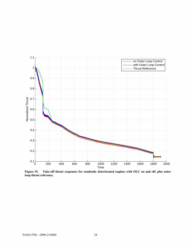
Figure 19. Take-off thrust responses for randomly deteriorated engines with OLC on and off, plus outer
loop thrust reference.
NASA/TM—2006-214460 24

1200 1300 1400 1500 1600 1700 1800 1900
0.14
0.16
0.18
0.2
0.22
0.24
0.26
0.28
Time
Nor
mal
ized
Thr
ust
no Outer Loop Controlwith Outer Loop ControlThrust Reference
Figure 20. Detail of Figure 19 (thrust responses for randomly deteriorated engines with OLC on and off,
plus outer loop thrust reference).
NASA/TM—2006-214460 25

D. Discussion The process of degradation is gradual and in general the outer loop compensation will not be noticeable. In cases
where the physical limit of the engine was not reached, the outer loop control is able to recover the nominal thrust.
In degradation cases that result in reduced thrust, the outer loop control will probably saturate PLA during take-off
when demand is high, but in a full implementation of the hierarchical architecture on a multi-engine aircraft (which
is not considered here) the thrust setpoint logic should be able to maintain thrust at an appropriate level so that a
yawing moment is not introduced, i.e. it might reduce the thrust demand slightly. However, most of the time
deterioration results in increased thrust and EGT, so outer loop thrust control can provide a benefit at takeoff when
temperature minimization is most important and at cruise when fuel consumption is most important.
The outer loop adjustment of PLA with a maximum PLA limit produces an unnecessarily conservative thrust
controller. The examples of thrust error due to PLA saturation could potentially be reduced or eliminated if the fan
speed command inside the FADEC were directly adjusted, especially if the fan speed limit is higher than what
maximum PLA represents. Since fan speed is actually the variable that corresponds to thrust output, limiting PLA
can result in a fan speed command that is too low, thus producing less than the desired thrust, even though the
controller itself is not hitting a limit. If the retrofit architecture were to be implemented within the FADEC, leaving
the existing control logic untouched, it makes sense for the outer loop to increment fan speed rather than PLA, as
long as the resulting total fan speed demand still passes through the limit logic.
The thrust estimator can be tuned in two ways which may have an impact on accuracy. First, the design
procedure allows for the incorporation of weights on specific variables,5 which can improve the estimation of some
variables at the expense of others. No non-unity weights were used in the example given here, but experimentation
with weights might have resulted in even better results. The second major design approach involves the use of a
common right factor, V*, and thus a common tuning vector q at all operating points; the alternative is to perform
SVD at each linearization point individually, which might provide better approximation by the reduced order model
0 200 400 600 800 1000 1200 1400 1600 1800 2000
−0.05
0
0.05
Time
Tun
ers
Figure 21. The seven tuners through the take-off transient of a degraded engine (noise-free).
NASA/TM—2006-214460 26

at each point. However, the approach used specifically avoids discontinuities that might occur in the estimation of q
as the engine moves between operating points, since the system matrices at individual operating points may have
significantly different singular values.
A standard, operating point-independent tuning vector q was derived for use here, as a result of the common V*
matrix in eq. (3). An idealized tuning vector, one which is insensitive to operating point, can potentially provide a
significant benefit for diagnostics because it should only be sensitive to degradation and faults.12
Figure 21 shows
the tuners for a single degraded case of a full take-off transient simulation, and it is clear that they are not constant
across the flight envelope, and are also affected by PLA movements. This result seems to indicate that, if it is
possible to obtain tuners that are consistent across the flight envelope, more work is needed to develop them.
V. Conclusions
Essential to the implementation of an intelligent retrofit turbine engine control and diagnostics architecture
(Figure 3), which was designed to reduce pilot workload, is the thrust estimator and outer loop thrust control. This
paper describes a real-time implementation of this portion of the architecture in simulation, which was evaluated for
robustness to the types of uncertainties that would be encountered in a real implementation. It was shown to work
well in all cases evaluated, up to the physical limits of the engine. The accuracy of the thrust estimation was good,
with the maximum mean estimation error of about 1.6% of nominal for the operating point. Using the thrust estimate
for feedback produced much tighter regulation of thrust than indirect control through fan speed. The incremental
control commands added by the system enter the FADEC and as such are still subject to the controller’s limit logic,
preventing any undesigned-for operation of the engine. Examples showed, however, that incrementing PLA into the
controller rather than fan speed command within the controller led to conservative performance and potential thrust
error; direct fan speed command adjustment should be investigated in future work. Because of the success in
regulating thrust over a wide operating range under a variety of deterioration conditions, it appears that a full
implementation of such an architecture is a viable approach for this application. The architecture greatly increases
the autonomy of the propulsion system, and thus enables the concept of an Intelligent Flight Control/Mission
Manager.
References 1Litt, J. S., et al., “A Survey of Intelligent Control and Health Management Technologies for Aircraft Propulsion Systems,”
Journal of Aerospace Computing, Information, and Communication [online journal], Vol. 1, No. 12, December 2004, pp. 543-
563, URL: www.aiaa.org/jacic/, [cited 2 September 2005]. 2Litt, J. S., Turso, J. A., Shah, N., Sowers, T. S., and Owen, A. K., “A Demonstration of a Retrofit Architecture for Intelligent
Control and Diagnostics of a Turbofan Engine,” Infotech@Aerospace, Arlington, VA , 26-29 Sept, 2005. 3Martucci, A., and Volponi, A.J., “Fuzzy Fuel Flow Selection Logic for a Real Time Embedded Full Authority Digital Engine
Control,” Journal of Engineering for Gas Turbines and Power, Vol. 125, Oct. 2003, pp. 909-916. 4Bosco, C. J., “Certification Issues For Electrical and/or Electronic Engine Controls,” SAE Paper 871844, Aerospace Technology
Conference and Exposition, Long Beach, CA, Oct. 5-8, 1987. 5Litt, J. S., “An Optimal Orthogonal Decomposition Method for Kalman Filter-Based Turbofan Engine Thrust Estimation,”
GT2005-68808, Proceedings of the 2005 ASME Turbo Expo, Reno-Tahoe, NV, June 6-9, 2005. 6Volponi, A. J., “Gas Turbine Parameter Corrections,” Journal of Engineering for Gas Turbines and Power, Vol. 121, October
1999, pp. 613-621. 7Kurzke, J., “Model Based Gas Turbine Parameter Corrections,” GT203-38234, Proceedings of 2003 ASME Turbo Expo, June
16-19, 2003. 8Kobayashi, T., Simon, D. L., “Evaluation of an Enhanced Bank of Kalman Filters for In-Flight Aircraft Engine Sensor Fault
Diagnostics,” Journal of Engineering for Gas Turbines and Power, Vol. 127, July 2005, pp. 497-504. 9Astrom, K. A., Hagglund, T., PID Controllers: Theory, Design, and Tuning, 2nd, Instrument Society of America, Research
Triangle Park, NC, 1995, pp. 88-91. 10The Aircraft Gas Turbine Engine and its Operation, Part No. PWA 182408, PWA Oper. Instr. 200, United Technologies
Corporation, Reprinted with revisions August 1988. 11Brunell, B. J., Viassolo, D. E., and Prasanth, R., “Model Adaptation and Nonlinear Model Predictive Control of an Aircraft
Engine,” GT–2004–53780, Proceedings of the 2004 ASME Turbo Expo, Vienna, Austria, 2004. 12Brotherton, T., Volponi, A., Luppold, R., and Simon, D.L., “eSTORM: Enhanced Self Tuning On-board Real-time Engine
Model,” Proceedings of the 2003 IEEE Aerospace Conference, Big Sky, MT, March 8-15, 2003.
NASA/TM—2006-214460 27

This publication is available from the NASA Center for AeroSpace Information, 301–621–0390.
REPORT DOCUMENTATION PAGE
2. REPORT DATE
19. SECURITY CLASSIFICATION OF ABSTRACT
18. SECURITY CLASSIFICATION OF THIS PAGE
Public reporting burden for this collection of information is estimated to average 1 hour per response, including the time for reviewing instructions, searching existing data sources,gathering and maintaining the data needed, and completing and reviewing the collection of information. Send comments regarding this burden estimate or any other aspect of thiscollection of information, including suggestions for reducing this burden, to Washington Headquarters Services, Directorate for Information Operations and Reports, 1215 JeffersonDavis Highway, Suite 1204, Arlington, VA 22202-4302, and to the Office of Management and Budget, Paperwork Reduction Project (0704-0188), Washington, DC 20503.
NSN 7540-01-280-5500 Standard Form 298 (Rev. 2-89)Prescribed by ANSI Std. Z39-18298-102
Form ApprovedOMB No. 0704-0188
12b. DISTRIBUTION CODE
8. PERFORMING ORGANIZATION REPORT NUMBER
5. FUNDING NUMBERS
3. REPORT TYPE AND DATES COVERED
4. TITLE AND SUBTITLE
6. AUTHOR(S)
7. PERFORMING ORGANIZATION NAME(S) AND ADDRESS(ES)
11. SUPPLEMENTARY NOTES
12a. DISTRIBUTION/AVAILABILITY STATEMENT
13. ABSTRACT (Maximum 200 words)
14. SUBJECT TERMS
17. SECURITY CLASSIFICATION OF REPORT
16. PRICE CODE
15. NUMBER OF PAGES
20. LIMITATION OF ABSTRACT
Unclassified Unclassified
Technical Memorandum
Unclassified
1. AGENCY USE ONLY (Leave blank)
10. SPONSORING/MONITORING AGENCY REPORT NUMBER
9. SPONSORING/MONITORING AGENCY NAME(S) AND ADDRESS(ES)
National Aeronautics and Space AdministrationWashington, DC 20546–0001andU.S. Army Research LaboratoryAdelphi, Maryland 20783–1145
National Aeronautics and Space AdministrationJohn H. Glenn Research Center at Lewis FieldCleveland, Ohio 44135–3191
Available electronically at http://gltrs.grc.nasa.gov
October 2006
NASA TM—2006-214460ARL–TR–3880AIAA–2006–5103
E–15724
33
Evaluation of an Outer Loop Retrofit Architecture for Intelligent TurbofanEngine Thrust Control
Jonathan S. Litt and T. Shane Sowers
Propulsion control; Diagnostics; Artificial intelligence
Unclassified -UnlimitedSubject Categories: 07, 08, 63
WBS 561581.02.01.03.03
The thrust control capability of a retrofit architecture for intelligent turbofan engine control and diagnostics is evaluated.
The focus of the study is on the portion of the hierarchical architecture that performs thrust estimation and outer loop
thrust control. The inner loop controls fan speed so the outer loop automatically adjusts the engine’s fan speed command
to maintain thrust at the desired level, based on pilot input, even as the engine deteriorates with use. The thrust estimation
accuracy is assessed under nominal and deteriorated conditions at multiple operating points, and the closed loop thrust
control performance is studied, all in a complex real-time nonlinear turbofan engine simulation test bed. The estimation
capability, thrust response, and robustness to uncertainty in the form of engine degradation are evaluated.
Prepared for the 42nd Joint Propulsion Conference and Exhibit cosponsored by the AIAA, ASME, SAE, and ASEE,Sacramento, California, July 9–12, 2006. Jonathan S. Litt, U.S. Army Research Laboratory, NASA Glenn ResearchCenter; and T. Shane Sowers, Analex Corporation, 1100 Apollo Drive, Brook Park, Ohio 44142. Responsible person,Jonathan S. Litt, organization code Z, 216–433–3748.


![lec13 x86procedure.ppt [相容模式]cyy/courses/assembly/08fall/...L2: ; begin the inner loop;; l oop L2 ; re pppeat the inner loo p pop ecx ; restore outer loop count loop L1 ; repeat](https://static.fdocuments.in/doc/165x107/5fb614b35457d74a9a1fd801/lec13-c-cyycoursesassembly08fall-l2-begin-the-inner-loop.jpg)